JP6173549B2 - Image data processing device, distance calculation device, imaging device, and image data processing method - Google Patents
Image data processing device, distance calculation device, imaging device, and image data processing method Download PDFInfo
- Publication number
- JP6173549B2 JP6173549B2 JP2016197732A JP2016197732A JP6173549B2 JP 6173549 B2 JP6173549 B2 JP 6173549B2 JP 2016197732 A JP2016197732 A JP 2016197732A JP 2016197732 A JP2016197732 A JP 2016197732A JP 6173549 B2 JP6173549 B2 JP 6173549B2
- Authority
- JP
- Japan
- Prior art keywords
- image data
- image
- correction function
- correction
- ratio
- Prior art date
- Legal status (The legal status is an assumption and is not a legal conclusion. Google has not performed a legal analysis and makes no representation as to the accuracy of the status listed.)
- Active
Links
Images


Landscapes
- Measurement Of Optical Distance (AREA)
- Focusing (AREA)
- Automatic Focus Adjustment (AREA)
- Studio Devices (AREA)
Description
本発明は、画像データ処理装置、距離算出装置、撮像装置および画像データ処理方法に関する。 The present invention relates to an image data processing device, a distance calculation device, an imaging device, and an image data processing method.
デジタルスチルカメラやデジタルビデオカメラにおいて、撮像素子の一部あるいは全部の画素に測距機能を有する画素(以下、「測距画素」ともいう。)を配置し、位相差方式で被写体までの距離を検出するようにした固体撮像素子が特許文献1に提案されている。測距画素は、複数の光電変換部を備え、撮影レンズの瞳上の異なる領域を通過した光束が、異なる光電変換部に導かれるように構成される。 In digital still cameras and digital video cameras, pixels having a ranging function (hereinafter also referred to as “ranging pixels”) are arranged on some or all of the pixels of the image sensor, and the distance to the subject is determined by a phase difference method. Patent Document 1 proposes a solid-state imaging device that detects the above. The ranging pixel includes a plurality of photoelectric conversion units, and is configured such that light beams that have passed through different regions on the pupil of the photographing lens are guided to different photoelectric conversion units.
各測距画素に含まれる光電変換部により生成された電気信号により、異なる瞳領域を通過した光束により生成される光像(以下、それぞれ「A像」、「B像」ともいい、両像をまとめて「AB像」ともいう。)に基づく画像データ(以降、A像に基づく画像をA画像、B像に基づく画像をB画像と呼ぶ。)を取得する。このA画像とB画像の相対的な位置ズレ量である像ズレ量(視差ともいう)を算出する。 Optical images generated by light beams that have passed through different pupil regions (hereinafter also referred to as “A image” and “B image”, respectively) by electrical signals generated by the photoelectric conversion unit included in each ranging pixel. Collectively, image data based on “AB image” (hereinafter, an image based on the A image is referred to as an A image and an image based on the B image is referred to as a B image) is acquired. An image shift amount (also referred to as parallax), which is a relative positional shift amount between the A image and the B image, is calculated.
像ズレ量の算出には、テンプレートマッチングと呼ばれる領域ベースの対応点探索技術が多く用いられる。テンプレートマッチングでは、A画像またはB画像を基準画像として設定し、基準画像とは異なる他方の画像を参照画像として設定する。基準画像上に、注目点を中心とする基準領域(基準ウィンドウともいう)を設定すると共に、参照画像上にて注目点と対応する参照点に対しても参照領域(参照ウィンドウともいう)を設定する。参照点を順次移動させながら、基準領域内の画像と参照領域内の画像の相関が最も高くなる参照点を探索し、注目点と参照点の相対的な位置ズレ量を用いて像ズレ量の算出を行う。一般に、探索領域のサイズを小さくすると、局所演算に起因する像ズレ量の算出誤差が発生するため、比較的大きな領域サイズ(例えば、9画素×9画素など)が用いられている。 For the calculation of the image shift amount, a region-based corresponding point search technique called template matching is often used. In template matching, an A image or a B image is set as a reference image, and the other image different from the reference image is set as a reference image. A reference area (also referred to as a reference window) centered on the target point is set on the reference image, and a reference area (also referred to as a reference window) is set for a reference point corresponding to the target point on the reference image. To do. While sequentially moving the reference point, a reference point having the highest correlation between the image in the reference area and the image in the reference area is searched, and the relative positional deviation between the target point and the reference point is used to determine the image deviation amount. Perform the calculation. In general, when the size of the search area is reduced, an image shift amount calculation error caused by local calculation occurs, and therefore a relatively large area size (for example, 9 pixels × 9 pixels) is used.
この像ズレ量を、変換係数を介してデフォーカス量に変換することで、被写体までの距離を算出できる。これによると、従来のコントラスト方式とは異なり、距離を測定するためにレンズを動かす必要が無いため、高速高精度な測距が可能となる。 By converting this image shift amount into a defocus amount through a conversion coefficient, the distance to the subject can be calculated. According to this, unlike the conventional contrast method, it is not necessary to move the lens to measure the distance, so that high-speed and high-precision distance measurement is possible.
ここで、測定の際の距離精度は、像ズレ量を正確に求めることで向上する。像ズレ量の誤差が発生する要因として、光量バランスの崩れが挙げられる。光量バランスの崩れとは、撮影レンズのレンズ枠などによる光束のケラレや測距画素感度の角度特性などにより、A像とB像の光量比が像高に応じて変化する現象である。 Here, the distance accuracy at the time of measurement is improved by accurately obtaining the image shift amount. A factor that causes an error in the amount of image shift is a loss of light amount balance. The loss of the light amount balance is a phenomenon in which the light amount ratio between the A image and the B image changes according to the image height due to the vignetting of the light beam by the lens frame of the photographing lens, the angle characteristic of the distance measuring pixel sensitivity, or the like.
特許文献2では、撮影レンズ及び撮像素子を組み立てた後に均一照明を与えることで、A像とB像の光量比が一定になる補正係数を算出し、像ズレ量算出時にこの補正係数を用いて画像データを補正する方法が提案されている。 In Patent Document 2, a uniform correction is applied after assembling the photographic lens and the image sensor to calculate a correction coefficient that makes the light quantity ratio between the A image and the B image constant, and this correction coefficient is used when calculating the image misalignment amount. A method for correcting image data has been proposed.
また、特許文献3では、光量バランスの崩れを、A像とB像の光量比を考慮した相互相関演算を行うことで補正する方法が提案されている。 Further, Patent Document 3 proposes a method for correcting the collapse of the light amount balance by performing a cross-correlation calculation in consideration of the light amount ratio between the A image and the B image.
特許文献2にて開示された焦点検出方法では、結像光学系及び撮像素子を組み立てた後に補正係数を計測するため、製造誤差の影響を受けることなくA像とB像の光量比を補正し、像ズレ量の算出誤差を低減させることができる。 In the focus detection method disclosed in Patent Document 2, the correction coefficient is measured after the imaging optical system and the image sensor are assembled, so that the light quantity ratio between the A image and the B image is corrected without being affected by manufacturing errors. Thus, the calculation error of the image shift amount can be reduced.
しかし、近年のデジタルカメラには光学式手ぶれ補正機能が搭載され、撮影レンズの光軸が、補正係数算出時と実際の撮影時とで異なる可能性がある。すなわち、予め取得した補正係数を用いる場合には、必ずしもA像とB像の光量バランスの崩れを良好に補正できるとは限らず、像ズレ量の算出精度が低下する恐れがある。また、撮影レンズと撮像素子を組み立てた後に補正係数を算出することは、調整工程が増えるために、製造コストが高くなる恐れもある。 However, recent digital cameras are equipped with an optical camera shake correction function, and there is a possibility that the optical axis of the photographing lens differs between when the correction coefficient is calculated and when actual photographing is performed. That is, when the correction coefficient acquired in advance is used, it is not always possible to satisfactorily correct the collapse of the light amount balance between the A image and the B image, and the calculation accuracy of the image shift amount may be reduced. In addition, calculating the correction coefficient after assembling the photographic lens and the image sensor increases the adjustment process, which may increase the manufacturing cost.
特許文献3にて開示された焦点検出方法では、探索領域内の画像と参照領域内の画像の相関度を算出する際に、A像とB像の光量比を考慮することにより光量バランスの崩れを補正し、像ズレ量の算出誤差を低減させることで測距精度を向上させている。 In the focus detection method disclosed in Patent Document 3, when calculating the correlation between the image in the search area and the image in the reference area, the light quantity balance is lost by considering the light quantity ratio between the A image and the B image. Is corrected and the calculation error of the image shift amount is reduced to improve the distance measurement accuracy.
テンプレートマッチングにおいては、隣接する注目点間にて、設定される基準領域の範囲に重複領域が存在する。特許文献3にて開示された焦点検出方法では、相関度の算出毎にA像とB像の光量バランスの崩れを補正しているために、重複領域において光量比の補正を複数回行うことになり、従来の相関度算出に比べて演算量が多くなる。演算量の増加は、処理時間の増大や演算回路の大規模化による高コスト化の恐れがある。また、基準領域内に含まれるA像とB像のみを考慮して光量バランスの崩れを補正しているため、光ショットノイズなどに代表されるノイズの影響により、精度良く光量バランスを補正できない恐れがある。 In template matching, there is an overlapping area in the range of the set reference area between adjacent points of interest. In the focus detection method disclosed in Patent Document 3, since the collapse of the light amount balance between the A image and the B image is corrected every time the degree of correlation is calculated, the light amount ratio is corrected a plurality of times in the overlapping region. As a result, the amount of calculation increases compared to the conventional correlation degree calculation. The increase in the amount of calculation may increase the processing time and increase the cost due to the large scale of the arithmetic circuit. In addition, since the balance of light quantity is corrected considering only the A and B images included in the reference area, there is a risk that the light quantity balance cannot be accurately corrected due to the influence of noise such as light shot noise. There is.
そこで本発明は、少ない演算量にて、A像とB像の光量バランスの崩れを補正することを目的とする。 The present invention is, with a small amount of calculation, an object of Rukoto to correct complement the collapse of the light intensity balance of the A and B images.
本発明に係る画像データ処理装置は、結像光学系の第1の瞳領域を通過する第1の光束に基づく第1の画像データと、前記結像光学系の前記第1の瞳領域と異なり且つ第1の方向に偏心している第2の瞳領域を通過する第2の光束に基づく第2の画像データと、を取得する画像データ取得手段と、前記第1の方向に沿った前記第1の画像データと前記第2の画像データの少なくとも一部の比である画像データ比を算出する画像データ比算出手段と、前記画像データ比に基づいて前記第1の方向における補正関数を算出する補正関数算出手段と、前記補正関数に基づき、前記第1の画像データと前記第2の画像データの少なくとも一方を補正する補正手段と、を備える。 The image data processing device according to the present invention is different from the first image data based on the first light flux passing through the first pupil region of the imaging optical system and the first pupil region of the imaging optical system. And second image data based on the second light flux passing through the second pupil region decentered in the first direction, and the first data along the first direction . An image data ratio calculating means for calculating an image data ratio that is a ratio of at least a part of the image data and the second image data, and a correction for calculating a correction function in the first direction based on the image data ratio A function calculating means; and a correcting means for correcting at least one of the first image data and the second image data based on the correction function .
本発明に係る画像データ処理方法は、結像光学系の第1の瞳領域を通過する第1の光束に基づく第1の画像データと、前記結像光学系の前記第1の瞳領域と異なり且つ第1の方向に偏心している第2の瞳領域を通過する第2の光束に基づく第2の画像データと、を取得する画像データ取得工程と、前記第1の方向に沿った前記第1の画像データと前記第2の画像データの少なくとも一部の比である画像データ比を算出する画像データ比算出工程と、前記画像データ比に基づいて前記第1の方向における補正関数を算出する補正関数算出工程と、前記補正関数に基づき、前記第1の画像データと前記第2の画像データの少なくとも一方を補正する補正工程と、を含む。 The image data processing method according to the present invention is different from the first image data based on the first light flux passing through the first pupil region of the imaging optical system and the first pupil region of the imaging optical system. And an image data acquisition step for acquiring second image data based on the second light flux passing through the second pupil region decentered in the first direction, and the first along the first direction . An image data ratio calculating step for calculating an image data ratio that is a ratio of at least a part of the image data and the second image data, and a correction for calculating a correction function in the first direction based on the image data ratio A function calculation step, and a correction step of correcting at least one of the first image data and the second image data based on the correction function .
本発明によれば、少ない演算量にて、像ズレ量を高精度に算出することができ、高精度な距離算出が可能となる。 According to the present invention, in no small amount of calculation, it is possible to calculate the image shift amount with high accuracy, high precision becomes possible distance calculation.
以下の説明では、本発明の距離算出装置を備えた撮像装置の一例として、デジタルカメラを用いて説明するが、本発明の適用はこれに限定されるものではない。例えば、本発明の距離算出装置はデジタル距離計測器などにも適用することができる。 In the following description, a digital camera will be used as an example of an imaging apparatus including the distance calculation device of the present invention, but the application of the present invention is not limited to this. For example, the distance calculation apparatus according to the present invention can be applied to a digital distance measuring instrument.
尚、図を参照した説明においては、図番は異なっても原則として同一部位を示す部位には、同一の符号を付すこととし、なるべく重複した説明は避ける。 In the description with reference to the figures, even if the figure numbers are different, in principle, the same reference numerals are given to the parts indicating the same parts, and overlapping explanations are avoided as much as possible.
[第1の実施形態]
以下、図を参照しながら本発明の第一の実施形態について詳細に説明する。
[First embodiment]
Hereinafter, a first embodiment of the present invention will be described in detail with reference to the drawings.
<デジタルカメラの構成>
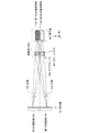
図1(A)は、本実施形態にかかるデジタルカメラ100の構成を示す図である。デジタルカメラ100は、結像光学系120、撮像素子101、距離算出部102、画像生成部(不図示)、レンズ駆動制御部(不図示)が、カメラ筐体130の内部に配置されて構成される。距離算出装置110は、結像光学系120、撮像素子101、距離算出部102から構成される。距離算出部102は論理回路を用いて構成することができる。距離算出部102の別の形態として中央演算処理装置(CPU)と演算処理プログラムを格納するメモリとから構成してもよい。
<Configuration of digital camera>
FIG. 1A is a diagram illustrating a configuration of a digital camera 100 according to the present embodiment. The digital camera 100 includes an imaging
結像光学系120は、デジタルカメラ100の撮影レンズであり、被写体の像を撮像面である撮像素子101に形成する機能を有する。結像光学系120は複数のレンズ群(不図示)、絞り(不図示)、光学式手ぶれ補正機構(不図示)から構成され、撮像素子101から所定距離離れた位置に射出瞳103を有する。光学式手ぶれ補正機構は、ジャイロ機構を備えた補正レンズから構成され、手ぶれを打ち消す方向に補正レンズを動作させることで、光軸のぶれを補正している。尚、図1(A)中の140は結像光学系120の光
軸である。本実施形態ではz軸を光軸140と平行とする。さらに、x軸とy軸は互いに垂直であり、且つ光軸140と垂直とする。
The imaging
ここで、このデジタルカメラ100の動作例について説明しておく。ただし、以下は、あくまで一例であり本発明を限定するものではない。図15はデジタルカメラ100のメイン電源が入り、シャッターボタン(不図示)が所謂半押しされた後の動作フローを説明する図である。まず、ステップ1501にて結像光学系120の情報(焦点距離、絞り値など)を読み出し、メモリ部(不図示)に保存する。次に、ステップ1502、1503、1504の処理を行い、焦点調節を行う。すなわち、ステップ1502では、撮像素子101から出力される画像データに基づき、図3を用いて後述する被写体距離算出手順を用いてデフォーカス量を算出する。ステップ1503では、算出したデフォーカス量に基づき、結像光学系120が合焦状態かどうか判別する。合焦していない場合は、ステップ1504にて、レンズ駆動制御部によりデフォーカス量に基づき結像光学系120を合焦位置へ駆動したのち、ステップ1502へ戻る。ステップ1503にて合焦していると判定された場合は、ステップ1505にて、シャッターボタン(不図示)の操作によりシャッターがレリーズ(所謂全押し)されたか否かの判定を行う。レリーズされていないと判定された場合は、ステップ1502へ戻り、上述の処理を繰り返す。ステップ1505にてシャッターがレリーズされたと判定された場合には、撮像素子101から画像データを読み出し、メモリ部(不図示)に保存する。メモリ部に保存された画像データに現像処理を施すことで、観賞用画像を生成することができる。また、メモリ部に保存された画像データに、図3を用いて後述する被写体距離算出手順を適用することで、観賞用画像と対応した被写体距離画像(被写体距離分布)を生成することができる。
Here, an operation example of the digital camera 100 will be described. However, the following is only an example and does not limit the present invention. FIG. 15 is a diagram for explaining the operation flow after the main power of the digital camera 100 is turned on and a shutter button (not shown) is half-pressed. First, in
<撮像素子の構成>
撮像素子101はCMOS(相補型金属酸化膜半導体)やCCD(電荷結合素子)から構成される。結像光学系120を介して撮像素子101上に結像した被写体像は、撮像素子101により光電変換され、被写体像に基づく画像データを生成する。以下、本実施形態の撮像素子101について、図1(B)を用いてより詳細に説明する。
<Configuration of image sensor>
The image sensor 101 is composed of a CMOS (complementary metal oxide semiconductor) or a CCD (charge coupled device). The subject image formed on the image sensor 101 via the imaging
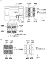
図1(B)は、撮像素子101のxy断面図である。撮像素子101は、2行×2列の画素群150を複数配列することで構成される。画素群150は、対角方向に緑画素150G1及び150G2、他の2画素に赤画素150R及び青画素150Bが配置され、構成されている。
FIG. 1B is an xy sectional view of the image sensor 101. The image sensor 101 is configured by arranging a plurality of 2 × 2 pixel groups 150. The pixel group 150 is configured by arranging green pixels 150G1 and 150G2 in a diagonal direction, and
<距離計測の原理説明>
本実施形態の画素群150を構成する各画素は、画素中の受光層(図2中の203)にxy断面にて対称な断面形状を有する2つの光電変換部(161:第1の光電変換部、162;第2の光電変換部)が並置されている。撮像素子101内の第1の光電変換部及び第2の光電変換部が受光する光束について、図2を用いて説明する。
<Description of the principle of distance measurement>
Each pixel constituting the pixel group 150 of the present embodiment includes two photoelectric conversion units (161: first photoelectric conversion) having a cross-sectional shape symmetrical with respect to the xy section in the light receiving layer (203 in FIG. 2) in the pixel.
図2は、結像光学系120の射出瞳103と、撮像素子101中に配置される画素の代表例として緑画素150G1についてのみ示した概略図である。図2に示した画素150G1は、カラーフィルタ201、マイクロレンズ202、受光層203から構成され、受光層203内に第1の光電変換部161と第2の光電変換部162が含まれている。マイクロレンズ202は、射出瞳103と受光層203が共役関係になるように配置されている。その結果、図2に示すように、射出瞳103内の第1の瞳領域261を通過した光束210は第1の光電変換部161に入射し、第2の瞳領域262を通過した光束220は第2の光電変換部162に入射する。
FIG. 2 is a schematic diagram showing only the exit pupil 103 of the imaging
各画素に設けられる複数の第1の光電変換部161は、受光した光束を光電変換して第
1の画像データを生成する。また同様に、各画素に設けられる複数の第2の光電変換部162は、受光した光束を光電変換して第2の画像データを生成する。第1の画像データから第1の瞳領域を主に通過した光束が撮像素子101上に形成する像(A像)の強度分布を得ることができ、第2の画像データから第2の瞳領域を主に通過した光束が撮像素子101上に形成する像(B像)の強度分布を得ることができる。従って、第1の画像データと第2画像データの相対的な位置ズレ量は、A像とB像の像ズレ量となる。この像ズレ量を後述の手法により算出し、変換係数を介して像ズレ量をデフォーカス量に変換することで、被写体までの距離を算出することができる。
The plurality of first
<距離算出手順の説明>
以下、本実施形態の距離算出部102が行う距離算出手順について、図3を参照しながら詳細に説明する。
<Explanation of distance calculation procedure>
Hereinafter, the distance calculation procedure performed by the distance calculation unit 102 of the present embodiment will be described in detail with reference to FIG.
ステップS1では、撮像素子101によって第1の画像データ及び第2の画像データを取得し、距離算出部102に伝送する(画像取得処理)。 In step S1, the image sensor 101 acquires the first image data and the second image data, and transmits them to the distance calculation unit 102 (image acquisition process).
ステップS2では、第1の画像データと第2の画像データに基づき、光量バランスの崩れを補正する光量バランス補正処理を行う。ステップS2における光量バランス補正処理については、図7を用いて後述する。 In step S2, a light amount balance correction process for correcting a break in the light amount balance is performed based on the first image data and the second image data. The light quantity balance correction process in step S2 will be described later with reference to FIG.
ステップS3では、第1の画像データと第2の画像データに基づき、像ズレ量の算出を行う。像ズレ量の算出方法について、図4を用いて説明する。図4は像ズレ量の算出方法を説明する図であり、第1の画像データ401、第2の画像データ402、撮影被写体400を示している。第1の画像データに対して、注目点410を設定し、注目点410を中心に基準領域420を設定する。一方、第2の画像データに対して、注目点410と対応する位置に参照点411を設定し、参照点411を中心に参照領域421を設定する。参照点411を所定の像ズレ量探索範囲内で順次移動させながら、基準領域420内の第1の画像データと参照領域421内の第2の画像データの相関値を算出し、最も相関の高い参照点411を注目点410の対応点とする。像ズレ量探索範囲は、距離算出を行いたい最大距離と最小距離から決めればよい。例えば最大距離は無限遠と設定し、最小距離は結像光学系120の最小撮影距離と設定し、最大距離と最小距離からそれぞれ求まる最大像ズレ量と最小像ズレ量の範囲を像ズレ量探索範囲とすればよい。注目点410と対応点間の相対的な位置シフト量が像ズレ量となる。注目点410を順次移動させながら対応点の探索を行うことで、第1の画像データ内の各データ位置(各画素位置)における像ズレ量を算出することができる。相関値の算出方法は公知の手法を用いることができ、例えば、基準領域内の各画素データと参照領域内の各画素データの差の2乗和を評価値とするSSDと呼ばれる手法を用いることができる。
In step S3, an image shift amount is calculated based on the first image data and the second image data. A method for calculating the image shift amount will be described with reference to FIG. FIG. 4 is a diagram for explaining a method of calculating the image shift amount, and shows first image data 401, second image data 402, and a
ステップS4では、変換係数を介して像ズレ量を像側デフォーカス量に変換している(デフォーカス量算出処理)。変換係数の算出方法について図5を用いて説明する。図5(A)は、画素における受光感度の入射角度依存性を示している。横軸は画素へ入射する光の入射角度(xz面に射影した光線とz軸とが成す角度)、縦軸は受光感度を示している。実線501は、第1の光電変換部161の受光感度を示し、破線502は、第2の光電変換部162の受光感度を示している。この受光感度を、射出瞳103に投影し、射出瞳103上の受光感度分布として表現したのが図5(B)である。色が濃くなるほど受光感度が高いことを示している。図5(B)には、第1の光電変換部の受光感度分布の重心位置511と、第2の光電変換部の受光感度分布の重心位置512が示されている。重心位置511と重心位置512間の距離513は基線長と呼ばれ、像ズレ量を像側デフォーカス量に変換するための変換係数として用いられる。像ズレ量をr、基線長をw、撮像素子101から射出瞳103までの瞳距離をLとしたとき像側デフォーカス量ΔLは、数式1
を用いて像ズレ量を像側デフォーカス量に変換することができる。

なお、数式1以外の方法を用いて像ズレ量を像側デフォーカス量に変換してもよい。例えば、数式1にて基線長wが像ズレ量rに比べて十分大きいとの仮定に基づき、数式2によりゲイン値Gainを算出し、数式3に基づき像ズレ量を像側デフォーカス量に変換してもよい。
![]()
![]()
数式3を用いることで像ズレ量から像側デフォーカス量への変換を容易に行うことができ、被写体距離の算出に係る演算量を削減することができる。また、像ズレ量から像側デフォーカス量への変換に、変換用のルックアップテーブルを用いてもよい。この場合にも、被写体距離の算出に係る演算量を削減することができる。
In step S4, the image shift amount is converted into the image-side defocus amount via the conversion coefficient (defocus amount calculation process). A method for calculating the conversion coefficient will be described with reference to FIG. FIG. 5A shows the incident angle dependence of the light receiving sensitivity in the pixel. The horizontal axis indicates the incident angle of light incident on the pixel (the angle formed by the light beam projected on the xz plane and the z axis), and the vertical axis indicates the light receiving sensitivity. A
Can be used to convert the image shift amount into the image-side defocus amount.
Note that the image shift amount may be converted into the image-side defocus amount using a method other than Equation 1. For example, based on the assumption that the baseline length w is sufficiently larger than the image shift amount r in Formula 1, the gain value Gain is calculated using Formula 2, and the image shift amount is converted into the image-side defocus amount based on Formula 3. May be.
![]()
![]()
By using Expression 3, conversion from the image shift amount to the image-side defocus amount can be easily performed, and the calculation amount related to the calculation of the subject distance can be reduced. Further, a conversion lookup table may be used for the conversion from the image shift amount to the image-side defocus amount. Also in this case, the amount of calculation related to the calculation of the subject distance can be reduced.
なお、図2において、第1の瞳領域261はxが負の領域とし、第2の瞳領域262はxが正の領域とし、完全に分離した領域であるものとして説明した。しかしながら、実際には受光層203に到達する光は、光の回折現象により一定の拡がりを有するため、図5(B)に受光感度分布を示すように第1の瞳領域261と第2の瞳領域262は重複した領域を有することになる。本実施形態においては、便宜的に第1の瞳領域261と第2の瞳領域262を明確に区分した形で説明する。 In FIG. 2, the first pupil region 261 is a region where x is negative, and the second pupil region 262 is a region where x is positive and completely separated. However, since the light reaching the light receiving layer 203 actually has a certain spread due to the light diffraction phenomenon, the first pupil region 261 and the second pupil as shown in FIG. 5B show the light receiving sensitivity distribution. The region 262 will have overlapping regions. In the present embodiment, the first pupil region 261 and the second pupil region 262 will be described in a clearly separated manner for convenience.
ステップS5では、ステップS4にて算出した像側デフォーカス量を、結像光学系の結像関係に基づき被写体距離への変換を行う(被写体距離算出処理)。なお、被写体距離への変換は、他の手法によって行ってもよい。例えば、像側のデフォーカス量を物体側のデフォーカス量に変換し、結像光学系120の焦点距離に基づき算出される物体側のピント位置と物体側のデフォーカス量の和により被写体までの距離を算出してもよい。物体側のデフォーカス量は、像側のデフォーカス量と結像光学系120の縦倍率を用いて算出できる。
In step S5, the image-side defocus amount calculated in step S4 is converted into a subject distance based on the imaging relationship of the imaging optical system (subject distance calculation process). The conversion to the subject distance may be performed by other methods. For example, the image-side defocus amount is converted into the object-side defocus amount, and the object-side defocus amount calculated based on the focal length of the imaging
本実施形態の距離算出手順では、ステップS4にて像ズレ量を像側のデフォーカス量に変換した後、ステップS5にて像側のデフォーカス量を被写体距離に変換している。しかし、前述の通り、像側のデフォーカス量と物体側のデフォーカス量または像側のデフォーカス量と被写体距離は、結像光学系120の結像関係を用いて変換可能である。従って、本実施形態のステップS4及び/またはステップS5を用いず、像ズレ量を直接物体側デフォーカス量または被写体距離へ変換しても構わない。いずれの場合においても、像ズレ量を正確に算出することで、精度良くデフォーカス量(像側及び/または物体側)や被写体距離を算出することができる。
In the distance calculation procedure of this embodiment, after the image shift amount is converted into the image-side defocus amount in step S4, the image-side defocus amount is converted into the subject distance in step S5. However, as described above, the image-side defocus amount and the object-side defocus amount or the image-side defocus amount and the subject distance can be converted by using the imaging relationship of the imaging
なお、本実施形態中では、ステップS5により像側のデフォーカス量を被写体距離に変換しているが、必ずしもステップS5を行う必要は無く、ステップS4にて距離算出手順を終了しても構わない。観賞用画像中の被写体のボケ量は像側のデフォーカス量に依存し
、像側のデフォーカス量が大きい被写体ほど、よりボケた画像が撮影される。このような画像に対して画像処理によってピント位置を調整するリフォーカス処理では、被写体距離への変換を行う必要はなく、像側のデフォーカス量があれば十分である。
In this embodiment, the image-side defocus amount is converted into the subject distance in step S5. However, step S5 is not necessarily performed, and the distance calculation procedure may be terminated in step S4. . The amount of blurring of the subject in the ornamental image depends on the defocus amount on the image side, and a subject with a larger defocus amount on the image side captures a more blurred image. In the refocus processing for adjusting the focus position by image processing for such an image, it is not necessary to perform conversion to the subject distance, and it is sufficient if there is a defocus amount on the image side.
<光量バランスの崩れが発生する要因>
次に、光量バランスの崩れが発生する要因について説明する。
<Factors causing the loss of light balance>
Next, factors that cause a loss of light amount balance will be described.
第1の光電変換部161が受光する光量1と、第2の光電変換部162が受光する光量2は、結像光学系120のヴィネッティング(口径蝕)により像高に依存して変化し、一般に撮像素子101の周辺領域ほど受光光量は低下する。図6(A)は、第1の光電変換部161が受光する光束と第2の光電変換部162が受光する光束のヴィネッティングを説明するための図である。第1の光電変換部161は、結像光学系120の射出瞳103上の第1の瞳領域261を通過した光束を受光し、第2の光電変換部162は、結像光学系120の射出瞳103上の第2の瞳領域262を通過した光束を受光する。
The amount of light 1 received by the first
中心像高601に位置する第1の光電変換部161と第2の光電変換部162が受光する光束621と光束622に対しては、光軸140に対して対称にヴィネッティングが発生する。したがって、光量1と光量2の比は1になる(光量バランスの崩れは生じない)。
Vignetting occurs symmetrically with respect to the optical axis 140 with respect to the light beam 621 and the light beam 622 received by the first
これに対し、周辺像高602に位置する第1の光電変換部161と第2の光電変換部162が受光する光束631と光束632に対しては、有効絞り610により光軸140に対して非対称にヴィネッティングが発生する。したがって、光量1と光量2の比が1とはならない(光量バランスの崩れが生じる)。
In contrast, the light beam 631 and the light beam 632 received by the first
また、光量バランスの崩れは、第1の光電変換部161と第2の光電変換部162が図5(A)に示すように入射角度依存性の高い感度特性を有することによっても発生する。図6(B)は、図5(A)と同様に画素の受光感度入射角度特性を示しており、中心像高601と周辺像高602が受光する光束の角度範囲を説明するための図である。
In addition, the loss of light amount balance also occurs when the first
中心像高601においては、光束621と光束622から構成される光束の主光線は、光軸と平行であるため、第1の光電変換部161と第2の光電変換部162は角度範囲603の光束を受光する。角度範囲603内では、第1の光電変換部161の受光感度を示す実線501の積分値(角度範囲603内の積分値)と第2の光電変換部162の受光感度を示す破線502の積分値(角度範囲603内の積分値)の比は1となる。すなわち、光量バランスの崩れは発生しない。
At the central image height 601, the principal ray of the light beam composed of the light beam 621 and the light beam 622 is parallel to the optical axis, and thus the first
これに対し、周辺像高602においては、光束631と光束632から構成される光束の主光線は、光軸とは平行とならず、第1の光電変換部161と第2の光電変換部162は角度範囲604の光束を受光する。角度範囲604内では、第1の光電変換部161の受光感度を示す実線501の積分値(角度範囲604内の積分値)と第2の光電変換部162の受光感度を示す破線502の積分値(角度範囲604内の積分値)の比は1とはならない。すなわち、光量バランスの崩れが生じる。
On the other hand, at the peripheral image height 602, the principal ray of the light beam composed of the light beam 631 and the light beam 632 is not parallel to the optical axis, and the first
本実施形態のデジタルカメラ100においては、結像光学系120のヴィネッティングと光電変換部の入射角度依存性との影響により、周辺像高において光量1と光量2の比が1とはならない光量バランスの崩れが発生する。
In the digital camera 100 of the present embodiment, the light amount balance in which the ratio of the light amount 1 and the light amount 2 does not become 1 at the peripheral image height due to the influence of the vignetting of the imaging
ステップS3の像ズレ量の算出処理においては、基準領域420と参照領域421間の相関(すなわち類似度)を評価しているため、光量バランスが崩れた場合には、誤った参
照点411にて相関が高いと判定し、算出される像ズレ量に誤差が生じてしまう。
In the image shift amount calculation processing in step S3, the correlation (that is, the degree of similarity) between the standard area 420 and the reference area 421 is evaluated. Therefore, when the light amount balance is lost, an incorrect reference point 411 is used. It is determined that the correlation is high, and an error occurs in the calculated image shift amount.
<光量バランス補正処理についての詳細説明>
以降、第1の画像データと第2の画像データの光量バランスの崩れを補正する処理(光量バランス補正処理)について、図7及び図8を参照しながら詳細に説明する。図7は本実施形態における光量バランス補正処理のフローチャートであり、図8は本実施形態における光量バランス補正処理を説明する図である。
<Detailed description of light quantity balance correction processing>
Hereinafter, a process of correcting the collapse of the light quantity balance between the first image data and the second image data (light quantity balance correction process) will be described in detail with reference to FIGS. FIG. 7 is a flowchart of the light quantity balance correction process in the present embodiment, and FIG. 8 is a diagram for explaining the light quantity balance correction process in the present embodiment.
ステップS2−1では、第1の画像データから第1の部分画像データを抽出し、第2の画像データから第2の部分画像データを抽出する処理を行う。図8(A)に示すように、第1の画像データ801から第1のデータ範囲821に含まれる第1の画像データを抽出し、第1の部分画像データ811とする。同様に、第2の画像データ802から第2のデータ範囲822に含まれる第2の画像データを抽出し、第2の部分画像データ812とする。第2のデータ範囲は、第1の画像データ内の第1のデータ範囲と対応する位置(第1の画像データ内の第1のデータ範囲の位置と、第2の画像データ内の第2のデータ範囲の位置は、相対的に同じ位置)に設定する。図8(B)は、光量バランスの崩れが生じないときの第1の画像データを第1の参考画像データ(実線803)として示し、光量バランスの崩れが生じないときの第2の画像データを第2の参考画像データ(破線804)として示している。なお、横軸はx方向の像高(画素位置)を示し、図8(A)中の一部の範囲830についてのみ示している。図8(B)においては、光量バランスの崩れが無いため、第1の参考画像データと第2の参考画像データは、x方向に相対的に位置がシフトした画像データとなっている。一方、図8(C)には、図8(A)中の範囲830に含まれる第1の部分画像データと第2の部分画像データを示す。図8(B)と図8(C)の比較から、光量バランスの崩れにより、第1の部分画像データのデータ値が低下していることが分かる。光量バランスの崩れを補正せずに、ステップS3の像ズレ量算出処理を行うと、誤った参照点にて相関が高いと判定し、算出される像ズレ量に誤差が生じることになる。 In step S2-1, the first partial image data is extracted from the first image data, and the second partial image data is extracted from the second image data. As shown in FIG. 8A, the first image data included in the first data range 821 is extracted from the first image data 801 as first partial image data 811. Similarly, the second image data included in the second data range 822 is extracted from the second image data 802 and used as second partial image data 812. The second data range is a position corresponding to the first data range in the first image data (the position of the first data range in the first image data and the second data range in the second image data). The position of the data range is set to the relatively same position). FIG. 8B shows the first image data when the light quantity balance is not broken as first reference image data (solid line 803), and the second image data when the light quantity balance is not broken. This is shown as second reference image data (broken line 804). Note that the horizontal axis indicates the image height (pixel position) in the x direction, and only a partial range 830 in FIG. In FIG. 8B, since there is no collapse of the light quantity balance, the first reference image data and the second reference image data are image data whose positions are relatively shifted in the x direction. On the other hand, FIG. 8C shows the first partial image data and the second partial image data included in the range 830 in FIG. From the comparison between FIG. 8B and FIG. 8C, it can be seen that the data value of the first partial image data is lowered due to the loss of the light amount balance. If the image shift amount calculation process in step S3 is performed without correcting the light intensity balance, it is determined that the correlation is high at the wrong reference point, and an error occurs in the calculated image shift amount.
本実施形態では、第1のデータ範囲821を第1の画像データ801の一部範囲に限定しているが、第1のデータ範囲821を第1の画像データ801の全域に設定しても構わない。望ましくは、第1のデータ範囲821を第1の画像データ801の全域にすることで、後述のステップS2−3における補正関数の算出に用いるデータ数を多くすることができ、近似誤差を低減することができる。 In the present embodiment, the first data range 821 is limited to a partial range of the first image data 801. However, the first data range 821 may be set to the entire area of the first image data 801. Absent. Desirably, by setting the first data range 821 to the entire area of the first image data 801, the number of data used for calculation of the correction function in step S2-3 to be described later can be increased, and the approximation error is reduced. be able to.
ステップS2−2では、第1の部分画像データと第2の部分画像データの比である画像データ比の算出をする処理(画像データ比算出処理)を行う。第1の部分画像データをPimg1(xp,yp)、第2の部分画像データをPimg2(xp,yp)、画像データ比をRimg(xp、yp)としたとき、画像データ比Rimgは、数式4に従い算出することができる。
なお、xpは部分画像データ中のx方向と対応する方向の座標値を示し、ypは部分画像データ中のy方向と対応する方向の座標値を示している。
In step S2-2, a process of calculating an image data ratio (image data ratio calculation process), which is a ratio between the first partial image data and the second partial image data, is performed. When the first partial image data is Pimg1 (xp, yp), the second partial image data is Pimg2 (xp, yp), and the image data ratio is Rimg (xp, yp), the image data ratio Rimg is expressed by Equation 4. It can be calculated according to
Note that xp indicates a coordinate value in a direction corresponding to the x direction in the partial image data, and yp indicates a coordinate value in a direction corresponding to the y direction in the partial image data.
ステップS2−3では、画像データ比Rimgを近似した補正関数Fnの算出処理を行う。本実施形態では、最小二乗法により補正関数Fnを算出する。すなわち、像高(xおよび/またはy)を変数とするN次多項式(N次関数)の係数を最小二乗近似により算出
し、これらの係数を有し像高(画素位置)を変数とするN次関数で表される補正関数Fnを採用する。なお、補正関数Fnの算出は最小二乗法以外にもスプライン法を用いることもできる。また、Nは1以上の自然数であれば任意の値で構わない。Nの値を大きくするほど補正関数算出処理の計算量が多くなるので、必要な精度と計算量とを比較して適切なNを採用すればよい。N=5でも十分な精度の光量バランスの補正が行えるので、Nとしては5以下の自然数を採用するようにしてもよい。なお、画像データ比Rimgは奇関数となるので、Nとして奇数の自然数を採用することが計算量の観点から好ましい。
In step S2-3, a correction function Fn calculation process approximating the image data ratio Rimg is performed. In the present embodiment, the correction function Fn is calculated by the least square method. That is, N-th order polynomial (Nth-order function) coefficients having an image height (x and / or y) as a variable are calculated by least square approximation, and these coefficients have an image height (pixel position) as a variable. A correction function Fn expressed by the following function is adopted. The calculation of the correction function Fn can use a spline method in addition to the least square method. N may be any value as long as it is a natural number of 1 or more. As the value of N is increased, the amount of calculation for the correction function calculation process increases. Therefore, an appropriate N may be adopted by comparing the required accuracy with the amount of calculation. Since the light quantity balance can be corrected with sufficient accuracy even when N = 5, a natural number of 5 or less may be adopted as N. Since the image data ratio Rimg is an odd function, it is preferable from the viewpoint of calculation amount to adopt an odd natural number as N.
より具体的にN=1とした時を例に説明する。本実施形態の撮像素子101では、第1の光電変換部161と第2の光電変換部162がx方向に並置されている。従って、本実施形態の距離算出装置110においては、A像(第1の画像データを構成する被写体像)とB像(第2の画像データを構成する被写体像)の相対的な位置ズレ(像ズレ)はx方向に発生する。以上を考慮すると、光量バランスの崩れはx方向に主として発生する。従って、本実施形態においては補正関数Fnをx方向の関数として数式5のように表わせる。
![]()
RimgとFnの差分二乗和が最小となるように、a(y)とb(y)を、y座標毎に算出すればよい。また、係数a(y)とb(y)をy座標毎に算出するのではなく、y座標に依存しない定数として算出しても構わない。
More specifically, the case where N = 1 is described as an example. In the image sensor 101 of the present embodiment, the first
![]()
What is necessary is just to calculate a (y) and b (y) for every y coordinate so that the sum of squared differences between Rimg and Fn is minimized. Further, the coefficients a (y) and b (y) may be calculated as constants that do not depend on the y coordinate instead of being calculated for each y coordinate.
補正関数の別の形態としては、補正関数Fnをx方向とy方向の関数として表しても構わない。例えば補正関数を3次関数で表現する場合には、数式6のように表し、各係数を公知の最小二乗法を用いて算出すればよい。なお、この場合も、補正関数Fnをy座標に依存しない形式で算出しても構わない。
![]()
最小二乗法の手法としては公知の手法を用いることができ、例えばQR分解法や特異値分解を用いることができる。また、光ショットノイズ等のノイズの影響を低減するために、画像データ比Rimgに公知の平滑化フィルタを施してから補正関数Fnを算出しても構わない。平滑化フィルタとしては、移動平均フィルタやガウシアンフィルタを用いることができる。
As another form of the correction function, the correction function Fn may be expressed as a function in the x direction and the y direction. For example, when the correction function is expressed by a cubic function, it is expressed as Equation 6 and each coefficient may be calculated using a known least square method. In this case as well, the correction function Fn may be calculated in a format independent of the y coordinate.
![]()
As a method of the least square method, a known method can be used. For example, a QR decomposition method or a singular value decomposition can be used. In order to reduce the influence of noise such as light shot noise, the correction function Fn may be calculated after applying a known smoothing filter to the image data ratio Rimg. As the smoothing filter, a moving average filter or a Gaussian filter can be used.
図8(D)はステップS2−2及びステップS2−3を説明するための図である。図8(D)中の実線831は、数式4に従い算出した範囲830内の画像データ比Rimgを示しており、破線841はN=3としてステップS2−3にて算出した範囲830内の補正関数Fnである。なお、横軸はx方向の像高である。画像データ比はバラつきを持ったデータ列となるが、画像データ比をN次関数で近似することで、バラつきの影響を低減した補正関数を得ることができる。 FIG. 8D is a diagram for explaining steps S2-2 and S2-3. A solid line 831 in FIG. 8D indicates the image data ratio Rimg within the range 830 calculated according to Equation 4, and a broken line 841 indicates a correction function within the range 830 calculated in step S2-3 with N = 3. Fn. The horizontal axis is the image height in the x direction. Although the image data ratio is a data string having variations, a correction function in which the influence of variations is reduced can be obtained by approximating the image data ratio with an N-order function.
ステップS2−4では、補正関数Fnを用いて第1の画像データを補正する処理を行う。第1の補正画像データは、補正関数Fnを用いて第1の画像データを補正した画像データであり、以下では、Cimg1(x、y)と表す。また同様に、第1の画像データはImg1(x、y)と表す。本実施形態では、第1の補正画像データCimg1を、数式7
に示すように、第1の画像データImg1と補正関数Fnの逆数に1を加えた関数(1+1/Fn:第1の画像データ補正関数)との乗算処理を行って算出している。
As shown in FIG. 5, the calculation is performed by multiplying the first image data Img1 by a function (1 + 1 / Fn: first image data correction function) obtained by adding 1 to the reciprocal of the correction function Fn.
ステップS2−5では、補正関数Fnを用いて第2の画像データを補正する処理を行う。第2の補正画像データは、補正関数Fnを用いて第2の画像データを補正した画像データであり、以下では、Cimg2(x、y)と表す。また同様に、第2の画像データはImg2(x、y)と表す。本実施形態では、第2の補正画像データCimg2を、数式8に示すように、第2の画像データImg2と補正関数Fnに1を加えた関数(1+Fn:第2の画像データ補正関数)の乗算処理を行って算出している。
![]()
![]()
図8(E)は、ステップS2−4及びステップS2−5を説明するための図である。図8(E)中の実線851は、数式7に従い算出した範囲830内の第1の補正画像データCimg1を示しており、破線852は数式8に従い算出した範囲830内の第2の補正画像データCimg2を示している。なお、横軸はx方向の像高である。図8(E)と図8(B)の比較から、本実施形態の光量バランス補正処理を用いることで、光量バランスの崩れを補正することができる。ステップS3(図3)では、このように光量バランスが補正された第1の補正画像データCimg1と第2の補正画像データCimg2を用いて像ズレ量が算出される。 FIG. 8E is a diagram for explaining steps S2-4 and S2-5. A solid line 851 in FIG. 8E indicates the first corrected image data Cimg1 within the range 830 calculated according to Equation 7, and a broken line 852 indicates the second corrected image data within the range 830 calculated according to Equation 8. Cimg2 is shown. The horizontal axis is the image height in the x direction. From a comparison between FIG. 8E and FIG. 8B, the use of the light amount balance correction process of the present embodiment can correct the collapse of the light amount balance. In step S3 (FIG. 3), the image shift amount is calculated using the first corrected image data Cimg1 and the second corrected image data Cimg2 in which the light quantity balance is corrected in this way.
上述ステップS2−1からステップS2−5の光量バランス補正処理では、第1の画像データと第2の画像データから抽出した第1の部分画像データと第2の部分画像データの比(画像データ比)に基づき、補正関数を算出している。局所領域のみに着目した場合、画像データ比は、第1の画像データと第2の画像データの光量バランスの崩れの他に、被写体距離に依存した像ズレに起因した比となる。しかしながら、撮影された画像内には、複数の被写体(人物と背景など)が配置される。各被写体は異なる距離に配置されており、さらに様々な空間周波数成分を持つことに起因して本実施形態の画像データ比はバラつきを持ったデータ列となる。本実施形態の光量バランス補正処理では、画像データ比を近似した補正関数を算出することで、画像データ比に含まれる被写体距離に依存した像ズレの影響を緩和している。その結果、予め光量バランスを補正するためのデータを取得することなく、第1の画像データと第2の画像データとに基づき、光量バランスの崩れを補正している。また、局所領域ではなく、画像データ比内の広い領域に着目して画像データ比を近似した補正関数を算出してもよい。こうすることで、画像データ比に含まれる被写体距離に依存した像ズレの影響だけではなく、第1の画像データ及び第2の画像データに含まれるノイズの影響を緩和することができる。画像データ比に含まれる被写体距離に依存した像ズレの影響を緩和するためには、第1のデータ範囲を、前述したステップS3の像ズレ量算出処理にて用いた基準領域420よりも広い範囲にすることが望ましい。またより望ましくは、第1のデータ範囲を、基準領域420と所定の像ズレ量探索範囲を合わせた範囲よりも広くとることが望ましい。いずれの場合においても、局所演算に起因するノイズの影響を低減することができる。 In the light intensity balance correction processing from step S2-1 to step S2-5 described above, the ratio (image data ratio) between the first partial image data and the second partial image data extracted from the first image data and the second image data. ) To calculate a correction function. When attention is paid only to the local region, the image data ratio is a ratio caused by the image shift depending on the subject distance in addition to the collapse of the light amount balance between the first image data and the second image data. However, a plurality of subjects (such as a person and a background) are arranged in the photographed image. Each subject is arranged at a different distance, and the image data ratio of the present embodiment is a data string having variations due to having various spatial frequency components. In the light quantity balance correction process of the present embodiment, the influence of image shift depending on the subject distance included in the image data ratio is reduced by calculating a correction function approximating the image data ratio. As a result, the collapse of the light amount balance is corrected based on the first image data and the second image data without acquiring data for correcting the light amount balance in advance. Alternatively, a correction function approximating the image data ratio may be calculated by focusing on a wide area within the image data ratio instead of the local area. In this way, not only the influence of image shift depending on the subject distance included in the image data ratio but also the influence of noise included in the first image data and the second image data can be reduced. In order to mitigate the effect of image shift depending on the subject distance included in the image data ratio, the first data range is wider than the reference area 420 used in the image shift amount calculation processing in step S3 described above. It is desirable to make it. More preferably, it is desirable that the first data range is wider than a range obtained by combining the reference region 420 and a predetermined image shift amount search range. In either case, it is possible to reduce the influence of noise caused by local computation.
本実施形態の光量バランス補正処理は、第1の画像データ及び第2の画像データに基づき補正関数を算出しているため、予め補正用のデータを取得する必要がない。従って、光学式手ぶれ補正機構により、結像光学系120の光軸が所定の位置からずれた場合においても、光量バランスの崩れを補正することができる。また、デジタルカメラ100を組み立てた後に、光量バランスを補正するための補正係数を計測する必要が無いため、製造時
の調整工程を削減することができ、より低コストにデジタルカメラ100を製造することができる。
In the light quantity balance correction process of the present embodiment, the correction function is calculated based on the first image data and the second image data, so that it is not necessary to acquire correction data in advance. Accordingly, even when the optical axis of the image forming
ステップS3の像ズレ量算出処理では、注目点410を順次移動させながら対応点探索を行う際に、隣接する注目点の間では基準領域が重複する。本実施形態の被写体算出手順では、ステップS2にて光量バランスを補正した後に、ステップS3の像ズレ量算出処理を行っているため、重複する領域の光量バランス補正を複数回行うことなく、被写体距離の算出を行うことができる。その為、少ない演算量で被写体距離の算出を行うことができる。 In the image shift amount calculation processing in step S3, when the corresponding point search is performed while sequentially moving the attention point 410, the reference regions overlap between adjacent attention points. In the subject calculation procedure of the present embodiment, since the image shift amount calculation processing in step S3 is performed after the light amount balance is corrected in step S2, the subject distance is corrected without performing the light amount balance correction in the overlapping region a plurality of times. Can be calculated. Therefore, the subject distance can be calculated with a small amount of calculation.
本実施形態の被写体距離算出手順では、第1の補正画像データと第2の補正画像データに基づき、ステップS3(図3)にて像ズレ量算出処理を行うことで、光量バランスの崩れに起因する像ズレ量の誤算出を低減している。 In the subject distance calculation procedure of the present embodiment, the image shift amount calculation process is performed in step S3 (FIG. 3) based on the first correction image data and the second correction image data, thereby causing the light amount balance to be lost. This reduces the erroneous calculation of the amount of image shift.
<光量バランス補正処理の変形例>
光量バランス補正処理の具体的な詳細は、上記で説明した方法から変更することができる。例えば、補正関数に基づく補正画像データの算出方法や、補正関数自体の算出方法を変形することができる。まず、補正関数に基づく補正画像データ算出処理の変形例を説明し、次に、補正関数算出処理の変形例を説明する。
<Modification of light intensity balance correction process>
Specific details of the light amount balance correction processing can be changed from the method described above. For example, the method for calculating the corrected image data based on the correction function and the method for calculating the correction function itself can be modified. First, a modified example of the corrected image data calculation process based on the correction function will be described, and then a modified example of the correction function calculation process will be described.
(補正画像データ算出方法の変形例)
本実施形態の光量バランス補正処理では、ステップS2−4にて第1の画像データを補正し、ステップS2−5にて第2の画像データを補正している。本実施形態の光量バランス補正処理の変形例として、第1の画像データ補正処理による第1の画像データの補正のみを行い、第2の画像データ補正処理を省略してもよい。この場合の第1の画像データ補正処理では、第1の補正画像データCimg1を、数式9に示すように、第1の画像データImg1と補正関数Fnの逆数との乗算処理によって算出する。
In the light amount balance correction process of the present embodiment, the first image data is corrected in step S2-4, and the second image data is corrected in step S2-5. As a modification of the light amount balance correction process of the present embodiment, only the first image data correction by the first image data correction process may be performed, and the second image data correction process may be omitted. In the first image data correction process in this case, the first corrected image data Cimg1 is calculated by multiplying the first image data Img1 and the inverse of the correction function Fn as shown in Equation 9.
ステップS2−4,S2−5の処理の代わりに、上記第1の画像データ補正処理(数式9)により第1の補正画像データを算出する場合には、第1の補正画像データと第2の画像データ(補正なし)に基づき、ステップS3にて像ズレ量算出処理を行う。上記第1の画像データ補正処理(数式9)は、第1の画像データの光量を、第2の画像データに合わせることで、光量バランスの崩れを補正している。 When the first corrected image data is calculated by the first image data correction process (Formula 9) instead of the processes of steps S2-4 and S2-5, the first corrected image data and the second corrected image data are calculated. Based on the image data (without correction), an image shift amount calculation process is performed in step S3. In the first image data correction process (Formula 9), the light quantity balance is corrected by matching the light quantity of the first image data with the second image data.
また、本実施形態の変形例として、第2の画像データ補正処理による第2の画像データの補正のみを行い、第1の画像データ補正処理を省略してもよい。この場合の第2の画像データ補正処理では、第2の補正画像データCimg2を、数式10に示すように、第2の画像データと補正関数Fnとの乗算処理によって算出する。
![]()
![]()
ステップS2−4,S2−5の処理の代わりに、上記第2の画像データ補正処理(数式10)により第2の補正画像データを算出する場合には、第1の画像データ(補正なし)と第2の補正画像データに基づき、ステップS3にて像ズレ量算出処理を行う。上記第2の画像データ補正処理(数式10)は、第2の画像データの光量を、第1の画像データに
合わせることで、光量バランスの崩れを補正している。
When the second corrected image data is calculated by the second image data correction process (Equation 10) instead of the processes of steps S2-4 and S2-5, the first image data (no correction) is used. Based on the second corrected image data, an image shift amount calculation process is performed in step S3. In the second image data correction process (Equation 10), the light quantity balance is corrected by matching the light quantity of the second image data with the first image data.
上記変形例では、第1の画像データと第2の画像データのいずれか一方のみを補正し、他方の光量に合わせることで、光量バランスの崩れを補正している。いずれか一方の画像データのみ光量バランス補正処理を行うことで、光量バランスの補正に必要な演算量をより削減することができる。 In the above modification, only one of the first image data and the second image data is corrected, and the light quantity balance is corrected by adjusting the light quantity to the other light quantity. By performing the light amount balance correction process on only one of the image data, the amount of calculation required for correcting the light amount balance can be further reduced.
(補正関数算出方法の変形例1)
以下では、図7を用いて説明した光量バランス補正処理とは一部が異なる光量バランス補正処理の別の形態について図9を用いて説明する。図9中のステップS2−1からステップS2−5は、図7を用いた説明と重複するため、以下では、新たに追加した処理であるステップS2−7からステップS2−9について説明する。
(Modification 1 of correction function calculation method)
Hereinafter, another embodiment of the light amount balance correction process, which is partially different from the light amount balance correction process described with reference to FIG. 7, will be described with reference to FIG. Steps S2-1 to S2-5 in FIG. 9 overlap with the description using FIG. 7, and therefore, steps S2-7 to S2-9, which are newly added processes, will be described below.
ステップS2−7は、補正関数Fnと画像データ比Rimgの類似度を示す相関度を算出する処理(相関度算出処理)である。相関度は、2つのデータ間の相関の度合いを表す値であればよく、例えば補正関数Fnと画像データ比Rimgの共分散を、それぞれの標準偏差で割った値である相関係数を用いることができる。ステップS2−3の説明と同様に、本実施形態の距離算出装置110においては、x方向に像ズレが発生することを考慮すると、相関係数は、y座標毎に算出しても構わない。 Step S2-7 is a process (correlation calculation process) for calculating a correlation indicating the similarity between the correction function Fn and the image data ratio Rimg. The degree of correlation only needs to be a value representing the degree of correlation between two data. For example, a correlation coefficient that is a value obtained by dividing the covariance of the correction function Fn and the image data ratio Rimg by each standard deviation is used. Can do. Similarly to the description of step S2-3, in the distance calculation device 110 of the present embodiment, the correlation coefficient may be calculated for each y coordinate in consideration of the occurrence of image shift in the x direction.
ステップS2−8は、ステップS2−7にて算出した相関度と所定の相関度判別閾値を比較し、相関度の高低を判別する処理(相関度判別処理)である。補正関数Fnと画像データ比Rimgの相関度が相関度判別閾値(第2の閾値に相当)より小さいと判別された場合には、ステップS2−9の処理へ進み、相関度判別閾値以上(第2の閾値以上)であると判別された場合には、ステップS2−4の処理へと進む。 Step S2-8 is a process (correlation degree determination process) for comparing the correlation degree calculated in step S2-7 with a predetermined correlation degree determination threshold value to determine the level of the correlation degree. If it is determined that the correlation between the correction function Fn and the image data ratio Rimg is smaller than the correlation determination threshold (corresponding to the second threshold), the process proceeds to step S2-9, and the correlation determination threshold or more (first If it is determined that it is equal to or greater than the threshold of 2, the process proceeds to step S2-4.
ステップS2−9は、補正関数Fnの次数を繰り上げるための処理を行う。ステップS2−8にて相関度が低いと判別された場合には、補正関数Fnの近似誤差が大きいと推定される。従って、ステップS2−9にて補正関数Fnの次数Nをより大きい値に変更した後に、ステップS2−3の補正関数Fnの算出処理を再度行う。例えば、NをN+1へ繰り上げる処理を行う。ここで、Nの増加量は固定値(例えば、1や2)であってもよいが、ステップS2−7にて算出した相関度に応じて、次数の繰り上げ幅を変えることが望ましい。相関度に応じて増加量を変えることで、補正関数Fnの近似誤差を小さくするために必要なステップS2−3の実行回数を少なくすることができ、演算量を低減することができる。このような手法の具体例として、以下のような方法を採用可能である。ステップS2−8の相関度を判別する閾値の1/2よりも相関度が小さい場合には、次数Nを4つ繰り上げる(例えば、次数Nが1である場合には、次数Nを5に変更して、ステップS2−3を再実行する)。一方、相関度が、ステップS2−8の相関度を判別する閾値の1/2以上であり、且つ閾値より小さい場合には、次数Nを2つ繰り上げる(例えば、次数Nが1である場合には、次数Nを3に変更して、ステップS2−3を再実行する)。 Step S2-9 performs processing for raising the order of the correction function Fn. If it is determined in step S2-8 that the degree of correlation is low, it is estimated that the approximation error of the correction function Fn is large. Therefore, after changing the order N of the correction function Fn to a larger value in step S2-9, the calculation process of the correction function Fn in step S2-3 is performed again. For example, a process of raising N to N + 1 is performed. Here, the increase amount of N may be a fixed value (for example, 1 or 2), but it is desirable to change the carry amount of the order according to the degree of correlation calculated in step S2-7. By changing the amount of increase in accordance with the degree of correlation, the number of executions of step S2-3 necessary for reducing the approximation error of the correction function Fn can be reduced, and the amount of calculation can be reduced. The following method can be adopted as a specific example of such a method. If the degree of correlation is smaller than 1/2 of the threshold value for determining the degree of correlation in step S2-8, the order N is incremented by 4 (for example, when the order N is 1, the order N is changed to 5). Step S2-3 is executed again). On the other hand, when the degree of correlation is not less than ½ of the threshold value for determining the degree of correlation in step S2-8 and smaller than the threshold value, the order N is incremented by 2 (for example, when the order N is 1). Change the order N to 3 and re-execute step S2-3).
上記ステップS2−7からステップS2−9の処理をさらに行うことで、補正関数の近似誤差が低減し、より精度良く第1の画像データと第2の画像データの光量バランスを補正することができる。その結果、本実施形態の被写体距離算出手順における被写体距離算出誤差を低減することができる。 By further performing the processing from step S2-7 to step S2-9, the approximation error of the correction function is reduced, and the light intensity balance between the first image data and the second image data can be corrected more accurately. . As a result, the subject distance calculation error in the subject distance calculation procedure of the present embodiment can be reduced.
(補正関数算出方法の変形例2)
以下では、図7を用いて説明した光量バランス補正処理とは一部が異なる光量バランス補正処理の別の形態について図10を用いて説明する。図10中のステップS2−1からステップS2−5は、図7を用いた説明と重複するため、以下では、新たに追加した処理
であるステップS2−10について説明する。
(Modification 2 of the correction function calculation method)
Hereinafter, another embodiment of the light amount balance correction process, which is partially different from the light amount balance correction process described with reference to FIG. 7, will be described with reference to FIG. Steps S2-1 to S2-5 in FIG. 10 are the same as those described with reference to FIG. 7, so step S2-10, which is a newly added process, will be described below.
ステップS2−10では、画像データ比Rimgから、光ショットノイズ等のノイズの影響や被写体距離に起因する像ズレの影響が大きいエラー値を除去する処理(近似点算出用データ生成処理)を、次のように行う。まず、画像データ比Rimgに微分フィルタを施して、微分画像データ比を算出する。そして、微分画像データ比の絶対値が所定の近似点判別閾値以下(第1の閾値以下)のデータ位置と対応する画像データ比内のデータ列のみを抽出し、新たに画像データ比を生成する。 In step S2-10, a process of removing an error value (approximate point calculation data generation process) from which the influence of noise such as light shot noise or the effect of image shift due to subject distance is large is removed from the image data ratio Rimg. Do as follows. First, a differential filter is applied to the image data ratio Rimg to calculate a differential image data ratio. Then, only the data string within the image data ratio corresponding to the data position where the absolute value of the differential image data ratio is equal to or less than the predetermined approximate point determination threshold (less than the first threshold) is extracted, and a new image data ratio is generated.
上記ステップS2−10の処理をさらに行うことで、補正関数の近似誤差が低減し、より精度良く第1の画像データと第2の画像データの光量バランスを補正することができる。その結果、本実施形態の被写体距離算出手順における被写体距離算出誤差を低減することができる。また、図10に記載のステップS2−3においては、スプライン法(スプライン補間)により補正関数を算出してもよい。すなわち、エラー値を除去した後の画像データ比を、x方向に複数の領域に区分し、N次のスプライン曲線を表すN次多項式を補正関数Fnとしても構わない。 By further performing the process of step S2-10, the approximation error of the correction function is reduced, and the light quantity balance between the first image data and the second image data can be corrected with higher accuracy. As a result, the subject distance calculation error in the subject distance calculation procedure of the present embodiment can be reduced. In step S2-3 shown in FIG. 10, a correction function may be calculated by a spline method (spline interpolation). That is, the image data ratio after removing the error value may be divided into a plurality of regions in the x direction, and an Nth order polynomial representing an Nth order spline curve may be used as the correction function Fn.
なお、図7を用いて説明した光量バランス補正処理に、図9に記載のステップS2−7からステップS2−9および図10に記載のステップS2−10の処理の両方を行うようにしても構わない。その際は、図11に示すフローで処理を行うようにしてもよい。すなわち、ステップS2−9の代わりに、補正関数Fnの次数を繰り上げる他に、近似点判別閾値の変更を追加したステップS2−9’を行っても構わない。ステップS2−9’を行った後は、ステップS2−10またはステップS2−3のいずれかの処理へと戻る。 It should be noted that in the light quantity balance correction processing described with reference to FIG. 7, both the processing from step S2-7 to step S2-9 shown in FIG. 9 and step S2-10 shown in FIG. 10 may be performed. Absent. In that case, you may make it process by the flow shown in FIG. That is, instead of step S2-9, step S2-9 'in which the change of the approximate point discrimination threshold is added may be performed in addition to increasing the order of the correction function Fn. After performing Step S2-9 ', the process returns to either Step S2-10 or Step S2-3.
図10及び図11を用いて説明した光量バランス補正処理においては、画像データ比に対して微分フィルタを作用させることで、エラー値を検出し、除去している。エラー値は、画像データ取得時に生じる各種ノイズ(光ショットノイズ等)や像ズレに起因して生じるため、エラー値を除去することで、より精度よく補正関数を生成できる。その結果、第1の画像データと第2の画像データの光量バランスを良好に補正することができ、精度よく被写体距離を算出することができる。 In the light quantity balance correction processing described with reference to FIGS. 10 and 11, an error value is detected and removed by applying a differential filter to the image data ratio. Since the error value is caused by various noises (such as light shot noise) and image deviation that occur during image data acquisition, the correction function can be generated more accurately by removing the error value. As a result, the light quantity balance between the first image data and the second image data can be favorably corrected, and the subject distance can be calculated with high accuracy.
<撮像素子101の別の形態>
本実施形態における撮像素子101の別の形態として、図12(A)に示すように、2種類の画素群150,1250を市松格子状に配列した構成としてもよい。画素群150は、第1の光電変換部161と第2の光電変換部162をx方向に配列した画素群である
。画素群150から得られる画像データに上記の距離算出処理を適用することで、x方向に輝度変化する被写体の距離を算出することができる。画素群1250は、第1の光電変換部161と第2の光電変換部162をy方向に配列した画素群1250に配列した画素群である。画素群1250から得られる画像データに上記の距離算出処理を適用することで、y方向に輝度変化する被写体の距離を算出することができる。
<Another Form of Image Sensor 101>
As another form of the image sensor 101 in this embodiment, as shown in FIG. 12A, two types of pixel groups 150 and 1250 may be arranged in a checkered pattern. The pixel group 150 is a pixel group in which a first
また、撮像素子101の別の形態として、図12(B)に示すように、2種類の測距画素群を採用してもよい。第1の測距画素群は、第1の光電変換部(161)のみを有する画素(緑画素150G1、赤画素150R1、青画素150B1)から構成される画素群である。第2の測距画素群は、第2の光電変換部162のみを有する画素(緑画素150G2、赤画素150R2、青画素150B2)から構成される画素群である。図12(B)に示すように第1の光電変換部161の面積を第2の光電変換部162よりも広くとる。各画素中の複数の第1の光電変換部161にて生成される画像データと各画素中の複数の第2の光電変換部162にて生成される画像データの差分データを前述の第1の画像データとすることで、被写体までの距離を算出することができる。
As another form of the image sensor 101, two types of ranging pixel groups may be employed as shown in FIG. The first ranging pixel group is a pixel group including pixels (green pixel 150G1, red pixel 150R1, blue pixel 150B1) having only the first
第1の光電変換部161により生成された画像データと第2の光電変換部162により生成された画像データとの間に、被写体の距離に応じた相対的な位置ズレが生じればよく、いずれの形態であっても被写体までの距離を算出することができる。
It is sufficient that a relative positional deviation corresponding to the distance of the subject occurs between the image data generated by the first
また、撮像素子101の別の形態として、図12(B)に示す第1の測距画素群の第1の光電変換部(161)は、結像光学系の第1の瞳領域を通過する第1の光束のみを受光するように構成してもよい。この場合、第1の光電変換部161にて生成される画像データが第1の画像データとなる。
As another form of the image sensor 101, the first photoelectric conversion unit (161) of the first ranging pixel group shown in FIG. 12B passes through the first pupil region of the imaging optical system. You may comprise so that only a 1st light beam may be received. In this case, the image data generated by the first
尚、測距画素を撮像素子101の全面に配置する必要はなく、測距画素を撮像素子101の一部領域にのみ配置し、他の領域については通常の撮像画素を配置する構成にしてもよい。撮影画素は、結像光学系120の射出瞳全体を通過する光束(第1および第2の光束)を受光および光電変換して撮影画像データを生成する光電変換部(第3の光電変換部)を備える。この場合、観賞用画像は、撮影画素から得られる画像データ(撮影画像データ)のみから生成してもよいし、撮影画素および測距画素から得られる画像データから生成してもよい。測距画素に比べて撮影画素は光電変換部の体積が大きいためにSN比の高い像信号を取得することができる。測距画素が占める領域と撮像用画素が占める領域の面積比を必要に応じて設定することで、被写体距離の算出精度と観賞用画像の画質を両立することができる。
It is not necessary to arrange the ranging pixels on the entire surface of the image sensor 101. The ranging pixels are arranged only in a part of the image sensor 101, and normal imaging pixels are arranged in other areas. Good. The imaging pixel receives and photoelectrically converts a light beam (first and second light beams) that passes through the entire exit pupil of the imaging
[第2の実施形態]
以下、図を参照しながら本発明の第二の実施形態について詳細に説明する。
[Second Embodiment]
Hereinafter, a second embodiment of the present invention will be described in detail with reference to the drawings.
以下の説明では、本発明の距離算出装置を備えた撮像装置の一例として、デジタルカメラを用いて説明するが、本発明の適用はこれに限定されるものではない。例えば、本発明の距離算出装置はデジタル距離計測器に適用することができる。 In the following description, a digital camera will be used as an example of an imaging apparatus including the distance calculation device of the present invention, but the application of the present invention is not limited to this. For example, the distance calculation device of the present invention can be applied to a digital distance measuring device.
尚、図を参照した説明においては、図番は異なっても原則として同一部位を示す部位には、同一の符号を付すこととし、なるべく重複した説明は避ける。 In the description with reference to the figures, even if the figure numbers are different, in principle, the same reference numerals are given to the parts indicating the same parts, and overlapping explanations are avoided as much as possible.
図13において、1300は本実施形態の距離算出装置1310を備えたデジタルカメラである。デジタルカメラ1300は、結像光学系120、撮像素子101、距離算出部102、画像生成部(不図示)、レンズ駆動制御部(不図示)、補正関数格納メモリ部1301、撮影条件取得部1302が、カメラ筐体130の内部に配置され、構成される。距離算出装置1310は、結像光学系120、撮像素子101、距離算出部102、補正関数格納メモリ部1301、撮影条件取得部1302から構成される。
In FIG. 13, reference numeral 1300 denotes a digital camera provided with the distance calculation device 1310 of the present embodiment. The digital camera 1300 includes an imaging
補正関数格納メモリ部1301には、過去の撮影時に算出した補正関数が撮影時の撮影条件と対応付けて格納されている。 In the correction function storage memory unit 1301, correction functions calculated at the time of past shooting are stored in association with shooting conditions at the time of shooting.
結像光学系120は、デジタルカメラ1300の撮影レンズであり、被写体の像を撮像面である撮像素子101に形成する機能を有する。結像光学系120は複数のレンズ群(不図示)、絞り(不図示)、光学式手ぶれ補正機構(不図示)から構成され、撮像素子101から所定距離離れた位置に射出瞳103を有する。光学式手ぶれ補正機構は、ジャイロ機構を備えた補正レンズから構成され、手ぶれを打ち消す方向に補正レンズを動作させることで、光軸のぶれを補正している。撮影条件取得部1302は、結像光学系120の焦点距離情報、絞り値情報、光軸のぶれを補正した量(設定値からの光軸のシフト量)などの撮影条件情報を取得している。
The imaging
<光量バランス補正処理についての詳細説明>
以降、本実施形態の光量バランス補正処理について、図14を参照しながら詳細に説明する。なお、図14中のステップS2−1からステップS2−5は、図7を用いた説明と重複するため、以降の説明ではステップS2−11からステップS2−14について説明する。
<Detailed description of light quantity balance correction processing>
Hereinafter, the light amount balance correction processing of the present embodiment will be described in detail with reference to FIG. Note that steps S2-1 to S2-5 in FIG. 14 are the same as those described with reference to FIG. 7, and therefore, in the following description, steps S2-11 to S2-14 will be described.
ステップS2−11では、撮影条件取得部1302から撮影条件情報を取得する処理を行う。 In step S2-11, processing for acquiring shooting condition information from the shooting condition acquisition unit 1302 is performed.
ステップS2−12は、撮影条件情報から、既に補正関数格納メモリ部1301に格納されている補正関数Fnを使用可能か判別する処理である。第1の画像データ及び第2の画像データを取得した時の撮影条件と、補正関数格納メモリ部1301に格納されている補正関数Fnを生成した時の撮影条件が異なる場合には、新たに補正関数Fnを生成する必要があるとして、ステップS2−1の処理へ進む。一方、撮影条件が、補正関数格納メモリ部1301に格納されている補正関数Fnを生成した時の撮影条件が略同一の場合には、ステップS2−13へ進む。撮影条件情報としては、例えば、焦点距離、絞り値、光軸のシフト量を用いることができる。 Step S2-12 is processing for determining whether or not the correction function Fn already stored in the correction function storage memory unit 1301 can be used from the photographing condition information. If the shooting condition when the first image data and the second image data are acquired differs from the shooting condition when the correction function Fn stored in the correction function storage memory unit 1301 is generated, a new correction is made. As it is necessary to generate the function Fn, the process proceeds to step S2-1. On the other hand, if the shooting conditions are substantially the same when the correction function Fn stored in the correction function storage memory unit 1301 is generated, the process proceeds to step S2-13. As the photographing condition information, for example, a focal length, an aperture value, and an optical axis shift amount can be used.
ステップS2−13は、補正関数格納メモリ部1301から補正関数Fnを読みだす処理を行う。 In step S2-13, the correction function Fn is read from the correction function storage memory unit 1301.
ステップS2−14は、ステップS2−3を経て算出した補正関数Fnを、補正関数格納メモリ部1301へ撮影条件と共に格納する処理を行う。 In step S2-14, the correction function Fn calculated in step S2-3 is stored in the correction function storage memory unit 1301 together with the shooting conditions.
本実施形態の距離算出装置1310は、距離算出部102内において、図14を用いて説明した光量バランス補正処理を行っている。これによると、過去に同一の撮影条件がある場合には、その時に生成した補正関数を読み出し、再利用することで、補正関数の算出にかかる処理を低減し、より短時間での被写体距離算出を可能としている。 The distance calculation device 1310 according to the present embodiment performs the light amount balance correction processing described with reference to FIG. 14 in the distance calculation unit 102. According to this, when there are the same shooting conditions in the past, the correction function generated at that time is read and reused to reduce the processing for calculating the correction function and calculate the subject distance in a shorter time. Is possible.
なお、本実施形態では、図14の光量バランス補正処理を用いたが、図9や図10を用いて説明した光量バランス補正処理に、上述のステップS2−11からステップS2−14の処理を加えた処理としても構わない。いずれの場合においても、補正関数を再利用することでより短時間での被写体距離算出を行うことができる。 In the present embodiment, the light intensity balance correction process of FIG. 14 is used. However, the processes of steps S2-11 to S2-14 are added to the light intensity balance correction process described with reference to FIGS. It does not matter if it is a process. In either case, the subject distance can be calculated in a shorter time by reusing the correction function.
上述した第1および第2の実施形態における距離算出装置の具体的な実装は、ソフトウェア(プログラム)による実装と、ハードウェアにより実装のいずれも可能である。例えば、撮像装置や画像処理装置に内蔵されたコンピュータ(マイコン、CPU、MPU、FPGA等)のメモリにコンピュータプログラムを格納し、当該コンピュータプログラムをコンピュータに実行させて、各処理を実現させてもよい。また、本発明の全部または一部の処理を論理回路により実現するASIC等の専用プロセッサを設けることも好ましい。また、本発明は、クラウド環境におけるサーバーにも適用可能である。 The specific implementation of the distance calculation device in the first and second embodiments described above can be implemented either by software (program) or by hardware. For example, each process may be realized by storing a computer program in a memory of a computer (microcomputer, CPU, MPU, FPGA, or the like) built in the imaging apparatus or the image processing apparatus, and causing the computer program to execute the computer program. . It is also preferable to provide a dedicated processor such as an ASIC that implements all or part of the processing of the present invention by a logic circuit. The present invention is also applicable to a server in a cloud environment.
また、例えば、記憶装置に記録されたプログラムを読み込み実行することで前述した実施形態の機能を実現するシステムや装置のコンピュータによって実行されるステップからなる方法によっても、本発明を実施することができる。この目的のために、上記プログラムは、例えば、ネットワークを通じて、又は、上記記憶装置となり得る様々なタイプの記録媒体(つまり、非一時的にデータを保持するコンピュータ読取可能な記録媒体)から、上記コンピュータに提供される。よって、上記コンピュータ(CPU、MPU等のデバイスを含む)、上記方法、上記プログラム(プログラムコード、プログラムプロダクトを含む)、上記プログラムを非一時的に保持するコンピュータ読取可能な記録媒体は、いずれ
も本発明の範疇に含まれる。
For example, the present invention can be implemented by a method including steps executed by a computer of a system or apparatus that implements the functions of the above-described embodiments by reading and executing a program recorded in a storage device. . For this purpose, the program is stored in the computer from, for example, various types of recording media that can serve as the storage device (ie, computer-readable recording media that holds data non-temporarily). Provided to. Therefore, the computer (including devices such as CPU and MPU), the method, the program (including program code and program product), and the computer-readable recording medium that holds the program in a non-temporary manner are all present. It is included in the category of the invention.
102 距離算出部
103 射出瞳
110 距離算出装置
120 結像光学系
DESCRIPTION OF SYMBOLS 102 Distance calculation part 103 Exit pupil 110
Claims (16)
前記第1の方向に沿った前記第1の画像データと前記第2の画像データの少なくとも一部の比である画像データ比を算出する画像データ比算出手段と、
前記画像データ比に基づいて前記第1の方向における補正関数を算出する補正関数算出手段と、
前記補正関数に基づき、前記第1の画像データと前記第2の画像データの少なくとも一方を補正する補正手段と、
を備える、画像データ処理装置。 A first based ku first image data to the light beam passing through the first pupil area of the image forming optical system, unlike the first pupil region of the imaging optical system and eccentric to the first direction and based Ku second image data to the second light flux passing through the second pupil area are, the image data acquisition means for acquiring,
Image data ratio calculating means for calculating an image data ratio that is a ratio of at least a part of the first image data and the second image data along the first direction ;
Correction function calculating means for calculating a correction function in the first direction based on the image data ratio;
Correction means for correcting at least one of the first image data and the second image data based on the correction function ;
An image data processing apparatus comprising:
請求項1に記載の画像データ処理装置。 The image data ratio calculation means calculates a ratio between the first partial image data included in the first image data and the second partial image data included in the second image data, and the image data ratio To calculate,
The image data processing apparatus according to claim 1.
請求項1または2に記載の画像データ処理装置。 The correction function calculation means uses only data included in the image data ratio at a position where the absolute value of the differential image data ratio obtained by applying a differential filter to the image data ratio is equal to or less than a predetermined first threshold value. To calculate the correction function,
The image data processing apparatus according to claim 1 .
請求項1から3のいずれか1項に記載の画像データ処理装置。 The correction function is an N-order function (N is a natural number).
The image data processing apparatus according to claim 1 .
前記相関度が、第2の閾値以上か否かを判別し、
前記補正関数と前記画像データ比との相関度が前記第2の閾値よりも低いと判別された場合には、次数Nの値をより大きくして前記補正関数算出手段による前記補正関数の算出を再度行う、
請求項4に記載の画像データ処理装置。 Calculating a correlation indicating a correlation between the correction function and the image data ratio;
Determining whether the correlation is greater than or equal to a second threshold;
If it is determined that the degree of correlation between the correction function and the image data ratio is lower than the second threshold, the correction function calculation means calculates the correction function by increasing the value of the order N. Do again,
The image data processing apparatus according to claim 4 .
請求項5に記載の画像データ処理装置。 When it is determined that the degree of correlation between the correction function and the image data ratio is lower than the second threshold, the order when the correction function is calculated again according to the value of the degree of correlation Set N,
The image data processing apparatus according to claim 5 .
を更に備え、
前記補正手段は、前記撮影条件取得手段によって取得した撮影条件に対応する前記既定の補正関数が前記補正関数格納手段に記憶されている場合には、当該記憶されている補正関数を用いて補正を行い、そうでない場合には、前記補正関数算出手段によって算出された補正関数を用いて補正を行う、
請求項1から6のいずれか1項に記載の画像データ処理装置。 Correction function storage means for storing a predetermined correction function determined in advance in association with the imaging conditions, and imaging condition acquisition means for acquiring the imaging conditions when the first image data and the second image data are acquired When,
Further comprising
When the predetermined correction function corresponding to the shooting condition acquired by the shooting condition acquisition unit is stored in the correction function storage unit, the correction unit performs correction using the stored correction function. If not, perform correction using the correction function calculated by the correction function calculation means,
Image data processing apparatus according to any one of claims 1 to 6.
前記第1の瞳領域が前記第2の瞳領域を含んでいる、
請求項1から7のいずれか1項に記載の画像データ処理装置。 The area of the first pupil region is larger than the area of the second pupil region,
The first pupil region includes the second pupil region;
Image data processing apparatus according to any one of claims 1 to 7.
前記補正手段により補正された画像データを用いて、前記第1の画像データと、前記第2の画像データと、の相対的な位置ズレ量である像ズレ量を算出する距離算出手段と、
を備える距離算出装置。 And an image data processing apparatus according to any one of claims 1 to 7,
A distance calculation unit that calculates an image shift amount, which is a relative positional shift amount between the first image data and the second image data, using the image data corrected by the correction unit;
A distance calculation device comprising:
前記補正手段により補正された画像データを用いて、前記第2の画像データと、前記第1の画像データと前記第2の画像データとの差分データである第3の画像データと、の相対的な位置ズレ量である像ズレ量を算出する距離算出手段と、
を備える距離算出装置。 An image data processing device according to claim 8 ,
Using the image data corrected by the correction means, the second image data and a relative relationship between the third image data that is difference data between the first image data and the second image data. Distance calculating means for calculating an image misalignment amount that is a large misalignment amount;
A distance calculation device comprising:
請求項9または10に記載の距離算出装置。 The distance calculating means calculates a defocus amount or a distance to the subject based on the image shift amount.
The distance calculation apparatus according to claim 9 or 10 .
前記結像光学系の第1の瞳領域を通過する第1の光束に基づく第1の画像データと前記結像光学系の第2の瞳領域を通過する第2の光束に基づく第2の画像データを取得する撮像素子と、
請求項1から8のいずれか1項に記載の画像データ処理装置、または、請求項9から11のいずれか1項に記載の距離算出装置と、
を備える撮像装置。 An imaging optical system;
First image data based on a first light flux passing through a first pupil region of the imaging optical system and a second image based on a second light flux passing through a second pupil region of the imaging optical system An image sensor for acquiring data;
The image data processing device according to any one of claims 1 to 8 , or the distance calculation device according to any one of claims 9 to 11 ,
An imaging apparatus comprising:
請求項12に記載の撮像装置。 The imaging device photoelectrically converts the first light flux to generate the first image data, and photoelectrically converts the second light flux to generate the second image data. Ranging pixels including a second photoelectric conversion unit, and imaging pixels including a third photoelectric conversion unit that photoelectrically converts the first and second light beams to generate captured image data.
The imaging device according to claim 12 .
請求項12に記載の撮像装置。 The imaging element photoelectrically converts the first light flux and first ranging pixels including a first photoelectric conversion unit that generates the first image data, and photoelectrically converts the second light flux. A second ranging pixel including a second photoelectric conversion unit that generates the second image data, and a third photoelectric conversion unit that generates captured image data by photoelectrically converting the first and second light beams. A photographic pixel comprising
The imaging device according to claim 12 .
前記第1の方向に沿った前記第1の画像データと前記第2の画像データの少なくとも一部の比である画像データ比を算出する画像データ比算出工程と、
前記画像データ比に基づいて前記第1の方向における補正関数を算出する補正関数算出工程と、
前記補正関数に基づき、前記第1の画像データと前記第2の画像データの少なくとも一方を補正する補正工程と、
を含む、画像データ処理方法。 The first image data based on the first light flux passing through the first pupil region of the imaging optical system and the first image data different from the first pupil region of the imaging optical system and decentered in the first direction. Image data acquisition step for acquiring second image data based on the second light flux passing through the two pupil regions;
An image data ratio calculating step of calculating an image data ratio that is a ratio of at least a part of the first image data and the second image data along the first direction ;
A correction function calculating step of calculating a correction function in the first direction based on the image data ratio;
A correction step of correcting at least one of the first image data and the second image data based on the correction function ;
Including an image data processing method.
Priority Applications (1)
| Application Number | Priority Date | Filing Date | Title |
|---|---|---|---|
| JP2016197732A JP6173549B2 (en) | 2016-10-06 | 2016-10-06 | Image data processing device, distance calculation device, imaging device, and image data processing method |
Applications Claiming Priority (1)
| Application Number | Priority Date | Filing Date | Title |
|---|---|---|---|
| JP2016197732A JP6173549B2 (en) | 2016-10-06 | 2016-10-06 | Image data processing device, distance calculation device, imaging device, and image data processing method |
Related Parent Applications (1)
| Application Number | Title | Priority Date | Filing Date |
|---|---|---|---|
| JP2013210114A Division JP6021780B2 (en) | 2013-10-07 | 2013-10-07 | Image data processing device, distance calculation device, imaging device, and image data processing method |
Publications (2)
| Publication Number | Publication Date |
|---|---|
| JP2017021052A JP2017021052A (en) | 2017-01-26 |
| JP6173549B2 true JP6173549B2 (en) | 2017-08-02 |
Family
ID=57889610
Family Applications (1)
| Application Number | Title | Priority Date | Filing Date |
|---|---|---|---|
| JP2016197732A Active JP6173549B2 (en) | 2016-10-06 | 2016-10-06 | Image data processing device, distance calculation device, imaging device, and image data processing method |
Country Status (1)
| Country | Link |
|---|---|
| JP (1) | JP6173549B2 (en) |
Cited By (3)
| Publication number | Priority date | Publication date | Assignee | Title |
|---|---|---|---|---|
| US9850702B2 (en) | 2003-08-20 | 2017-12-26 | Hunter Douglas Inc | Method for making a window covering having operable vanes |
| US10030438B2 (en) | 2003-08-20 | 2018-07-24 | Hunter Douglas Inc. | Retractable shade with collapsible vanes |
| US10648228B2 (en) | 2010-03-23 | 2020-05-12 | Hunter Douglas Inc. | System for biasing sheet of material to gather in predetermined direction |
Family Cites Families (8)
| Publication number | Priority date | Publication date | Assignee | Title |
|---|---|---|---|---|
| JP2004191629A (en) * | 2002-12-11 | 2004-07-08 | Canon Inc | Focus detector |
| JP4946059B2 (en) * | 2006-01-11 | 2012-06-06 | 株式会社ニコン | Imaging device |
| JP5338119B2 (en) * | 2008-04-14 | 2013-11-13 | 株式会社ニコン | Correlation calculation device, focus detection device, and imaging device |
| JP5237077B2 (en) * | 2008-12-16 | 2013-07-17 | キヤノン株式会社 | FOCUS DETECTION DEVICE, ITS CONTROL METHOD, AND PROGRAM |
| JP5454223B2 (en) * | 2010-02-25 | 2014-03-26 | 株式会社ニコン | camera |
| JP2012008424A (en) * | 2010-06-28 | 2012-01-12 | Olympus Corp | Imaging system |
| JP5943655B2 (en) * | 2012-03-12 | 2016-07-05 | キヤノン株式会社 | Image processing apparatus, focus detection apparatus, and image processing program |
| JP5548761B2 (en) * | 2012-12-17 | 2014-07-16 | キヤノン株式会社 | Imaging apparatus, imaging system, and focus detection method |
-
2016
- 2016-10-06 JP JP2016197732A patent/JP6173549B2/en active Active
Cited By (5)
| Publication number | Priority date | Publication date | Assignee | Title |
|---|---|---|---|---|
| US9850702B2 (en) | 2003-08-20 | 2017-12-26 | Hunter Douglas Inc | Method for making a window covering having operable vanes |
| US10030438B2 (en) | 2003-08-20 | 2018-07-24 | Hunter Douglas Inc. | Retractable shade with collapsible vanes |
| US10604996B2 (en) | 2003-08-20 | 2020-03-31 | Hunter Douglas Inc. | Retractable shade with collapsible vanes |
| US10604997B2 (en) | 2003-08-20 | 2020-03-31 | Hunter Douglas Inc. | Apparatus and method for making a window covering having operable vanes |
| US10648228B2 (en) | 2010-03-23 | 2020-05-12 | Hunter Douglas Inc. | System for biasing sheet of material to gather in predetermined direction |
Also Published As
| Publication number | Publication date |
|---|---|
| JP2017021052A (en) | 2017-01-26 |
Similar Documents
| Publication | Publication Date | Title |
|---|---|---|
| JP6021780B2 (en) | Image data processing device, distance calculation device, imaging device, and image data processing method | |
| JP6643122B2 (en) | Range image apparatus, imaging apparatus, and range image correction method | |
| JP6202927B2 (en) | Distance detection device, imaging device, program, recording medium, and distance detection method | |
| US10477100B2 (en) | Distance calculation apparatus, imaging apparatus, and distance calculation method that include confidence calculation of distance information | |
| US20180007253A1 (en) | Focus detection apparatus, focus control apparatus, image capturing apparatus, focus detection method, and storage medium | |
| JP2008122835A (en) | Correlation calculation method, correlation calculation device, focus detector and imaging apparatus | |
| JP6173549B2 (en) | Image data processing device, distance calculation device, imaging device, and image data processing method | |
| JP6116151B2 (en) | Distance detector | |
| US20150319357A1 (en) | Ranging apparatus, imaging apparatus, ranging method and ranging parameter calculation method | |
| JP2018071979A (en) | Distance detector and distance detection method | |
| WO2014073401A2 (en) | Distance measuring apparatus | |
| JPS59107313A (en) | Focus detecting signal processing method | |
| US10339665B2 (en) | Positional shift amount calculation apparatus and imaging apparatus | |
| JP5338112B2 (en) | Correlation calculation device, focus detection device, and imaging device | |
| JP2015203756A (en) | Parallax amount calculation device, distance calculation device, imaging apparatus, and parallax amount calculation method | |
| JP4817552B2 (en) | Phase difference detection method, phase difference detection device, distance measuring device, and imaging device | |
| JP2019070610A (en) | Distance measuring apparatus and distance measuring method | |
| US11070715B2 (en) | Image shift amount calculation apparatus and method, image capturing apparatus, defocus amount calculation apparatus, and distance calculation apparatus | |
| US9402069B2 (en) | Depth measurement apparatus, imaging apparatus, and method of controlling depth measurement apparatus | |
| JP6632406B2 (en) | Distance calculation device, imaging device, and distance calculation method | |
| JP2016090975A (en) | Distance detector, imaging apparatus, distance detection method, and program | |
| JP6590463B2 (en) | Distance calculation device | |
| JP5932361B2 (en) | Distance information detection apparatus, distance information detection method, and camera | |
| WO2013133115A1 (en) | Defocus amount detection device and camera | |
| JP2014102478A (en) | Autofocus device and imaging apparatus |
Legal Events
| Date | Code | Title | Description |
|---|---|---|---|
| A521 | Request for written amendment filed |
Free format text: JAPANESE INTERMEDIATE CODE: A523 Effective date: 20161101 |
|
| A621 | Written request for application examination |
Free format text: JAPANESE INTERMEDIATE CODE: A621 Effective date: 20161101 |
|
| A871 | Explanation of circumstances concerning accelerated examination |
Free format text: JAPANESE INTERMEDIATE CODE: A871 Effective date: 20161101 |
|
| A975 | Report on accelerated examination |
Free format text: JAPANESE INTERMEDIATE CODE: A971005 Effective date: 20161227 |
|
| A131 | Notification of reasons for refusal |
Free format text: JAPANESE INTERMEDIATE CODE: A131 Effective date: 20170110 |
|
| A521 | Request for written amendment filed |
Free format text: JAPANESE INTERMEDIATE CODE: A523 Effective date: 20170301 |
|
| TRDD | Decision of grant or rejection written | ||
| A01 | Written decision to grant a patent or to grant a registration (utility model) |
Free format text: JAPANESE INTERMEDIATE CODE: A01 Effective date: 20170606 |
|
| A61 | First payment of annual fees (during grant procedure) |
Free format text: JAPANESE INTERMEDIATE CODE: A61 Effective date: 20170704 |
|
| R151 | Written notification of patent or utility model registration |
Ref document number: 6173549 Country of ref document: JP Free format text: JAPANESE INTERMEDIATE CODE: R151 |