JP4817552B2 - Phase difference detection method, phase difference detection device, distance measuring device, and imaging device - Google Patents
Phase difference detection method, phase difference detection device, distance measuring device, and imaging device Download PDFInfo
- Publication number
- JP4817552B2 JP4817552B2 JP2001243917A JP2001243917A JP4817552B2 JP 4817552 B2 JP4817552 B2 JP 4817552B2 JP 2001243917 A JP2001243917 A JP 2001243917A JP 2001243917 A JP2001243917 A JP 2001243917A JP 4817552 B2 JP4817552 B2 JP 4817552B2
- Authority
- JP
- Japan
- Prior art keywords
- video data
- pair
- correlation
- phase difference
- correction
- Prior art date
- Legal status (The legal status is an assumption and is not a legal conclusion. Google has not performed a legal analysis and makes no representation as to the accuracy of the status listed.)
- Expired - Fee Related
Links
Images


Landscapes
- Measurement Of Optical Distance (AREA)
- Focusing (AREA)
- Automatic Focus Adjustment (AREA)
Description
【0001】
【発明の技術分野】
本発明は、位相差検出方法、位相差検出装置、測距装置および撮像装置に関する。
【0002】
【従来の技術】
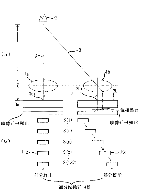
従来、自動焦点カメラにおいて、いわゆるパッシブ方式で被写体にピントを合わせる際、非TTLカメラの場合は撮影レンズを通過していない被写体像を用いて被写体距離を検出した後にその検出した被写体距離に応じて撮影レンズの位置を制御しており、TTLカメラの場合は撮影レンズを通過して得られた被写体像を用いて合焦状態からのずれ量を検出した後にその検出したずれ量に応じて撮影レンズの位置を制御している。以下、図3(a)を参照して上述した動作原理を説明する。
【0003】
同図において、1対のレンズ1aと1bは所定の基線長bだけ離して配設してあり、1対のレンズ1aと1bから焦点距離fだけ離して配設された1対の光センサアレイ3aと3bに互いに異なる光路AとBを介して対象2の映像をそれぞれ結像させる。対象2は1対のレンズ1a、1bから正面方向に距離Lだけ離れた位置に存在するものとする。
【0004】
対象2が無限遠の位置に存在するとき一対の光センサアレイ3aと3bに結像される映像の中心は光センサアレイ3a、3b上のレンズ1a、1bの光軸に対応する基準位置(3a1、3b1)に結像されるが、対象2が無限遠位置よりも近づくと、これら基準位置(3a1、3b1)からαだけずれた位置に結像される。三角測距の原理から対象2までの距離LはL=bf/αとなる。ここで、基線長bと焦点距離fは定数なので、ずれ量αを検出すれば距離Lを測定できる。これが非TTLカメラに用いられているパッシブ測距(いわゆる外光三角測距)の原理である。なお、非TTLカメラでは測距装置の出力値として距離Lを用いるかわりにずれ量αをそのまま使う場合もある。本願では、このずれ量αを位相差と称する。
【0005】
TTLカメラの場合は、撮像レンズ(図示せず。)を通過した光を一対のレンズ1a、1bに与えて上記と同様に左右の映像対間の位相差αを検出する。なお、この場合は合焦状態にあるときの映像の中心を各光センサアレイ3a、3b上の基準位置とする。よって、位相差αの正負が前ピント状態か後ピント状態かをその絶対値が合焦からのずれの程度をそれぞれ示す。
【0006】
これらはいずれも光学系により対象の映像を1対の光センサアレイ上に結像させ、1対の光センサアレイが出力する1対の映像信号の相対的な位置ずれ、すなわち位相差を1対の映像信号からそれぞれ抽出した部分映像データ群(図3(b)参照)について相関演算を行うことにより検出している。なお、このような位相差検出は自動焦点カメラに限るものではなく、種々の測距装置や焦点検出装置等に用いることが可能である。
【0007】
このような位相差を検出する方式において、被写体の背景に太陽等の強い光源がある場合などに発生するフレア等の迷光に起因する検出精度の悪化を低減する方式として、例えば特開平8−166237号公報に開示されたものがある。具体的には3つの技術が開示されており、第1の技術は1対の光センサが出力する1対のセンサデータの平均値が2つのセンサデータ間で差がなくなるように補正する技術、第2の技術は1対のセンサデータから抽出した部分映像データ群の組合せごとに両部分映像データ群間の代表値に差がなくなるように補正する技術、第3の技術は1対のセンサデータの各データ値をデータ変数番号に関する微分近似値で置き換えるように補正する技術である。
【0008】
【発明が解決しようとする課題】
しかしながら、上記第1の技術すなわち1対の光センサが出力する1対のセンサデータの平均値が2つのセンサデータ間で差がなくなるように補正する場合は、相関演算を行う際に用いる部分映像データ群がその部分映像データ群に含まれないセンサデータ間の誤差の影響を受けてしまう。よって、例えば、補正しない状態で最も相関度の高くなる部分映像データ群の組合せがフレアによる影響を受けていなく、他の部分がフレアによる影響を受けている場合、補正後のほうが補正前より位相差検出精度が悪化してしまうという問題点を有していた。
【0009】
また、上記第2の技術すなわち1対のセンサデータから抽出した部分映像データ群の組合せごとに両部分映像データ群間の代表値に差がなくなるように補正する場合は、部分映像データ群の組合せごとに補正量を求めなければならなくなり、部分映像データ群の組合せ数が多くなるほど処理動作が増大してしまうという問題点を有していた。
【0010】
また、上記第3の技術すなわち1対のセンサデータの各データ値をデータ変数番号に関する微分近似値で置き換えるように補正する場合は、個々のデータに対して複雑な微分近似値置換え処理が必要となる。
【0011】
本発明は、複雑な処理および検出精度の悪化を可及的に抑制可能な位相差検出方法、位相差検出装置、測距装置および撮像装置を提供することを目的とする。
【0012】
【課題を解決するための手段】
第1の発明は、測定対象からの像が結像される1対の光センサアレイの出力に応じた複数の映像データからなる1対の映像データ列から相対位置が異なる部分映像データ群を抽出して1対の部分映像データ群の組合せを複数作り、当該1対の部分映像データ群の各組合せに対して複数の相関度を求める相関度取得ステップと、当該複数の相関度の中で最大相関度を示す上記1対の部分映像データ群から求められた最大相関度と所定値との差を上記複数の1対の部分映像データ群の一方の部分映像データ群の映像データの数で割って得られる補正値を求める補正値取得ステップと、上記複数の部分映像データ群の各組合せ毎に上記1対の部分映像データ群の映像データ列を上記補正値に基づき補正する補正ステップと、補正後の上記映像データに基づいて補正後の複数の相関度を求める相関度取得ステップと、補正前の最大相関度と補正後の最大相関度を比較し相関度の高い最大相関度を含む複数の相関度を有効相関度と判定する比較判定ステップと、上記有効相関度と判定された複数の相関度と相関度が求められた時の上記相対位置を基にして上記1対のセンサアレイに結像された像の相互間の位相差を検出する位相差検出ステップとを含む位相差検出方法である。このようなステップを含む方法によれば、最大相関度を示す1対の部分映像データ群の差に応じた補正値により1対のセンサアレイに結像された像の相互間の位相差を検出するために用いる映像データ間のデータ差を補正するので、もともと相関度が高い1対の部分映像データ群の差に基づいた補正が行え、もともと相関度が高くないデータの影響を受けることを低減でき、部分映像データ群の組合せごとに補正量を求めるという煩わしい処理を防止でき、個々のデータに対して複雑な微分近似値置換え処理をなくすことが可能となる。
【0013】
第2の発明は、測定対象からの像が結像される1対のセンサアレイと、上記1対のセンサアレイの出力に応じた複数の映像データからなる1対の映像データ列から相対位置が異なる部分映像データ群を抽出して1対の部分映像データ群の組合せを複数作り、当該1対の部分映像データ群の各組合せに対して複数の相関度を求める相関演算部と、上記複数の相関度の中で最大相関度を示す上記1対の部分映像データ群から求められた最大相関度と所定値との差を上記複数の1対の部分映像データ群の一方の部分映像データ群の映像データの数で割って得られる補正値を求める補正値取得部と、上記複数の部分映像データ群の各組合せ毎に上記1対の部分映像データ群の映像データ列を上記補正値に基づき補正する補正部と、上記補正部により補正された上記映像データに基づいて補正後の複数の相関度を求める相関演算部と、補正前の最大相関度と補正後の最大相関度を比較し相関度の高い最大相関度を含む複数の相関度を有効相関度と判定する比較判定部と、上記有効相関度と判定された複数の相関度と相関度が求められた時の上記相対位置を基にして上記1対のセンサアレイに結像された像の相互間の位相差を検出する位相差検出部とを含む位相差検出装置である。このような構成によれば、最大相関度を示す1対の部分映像データ群の差に応じた補正値により1対のセンサアレイに結像された像の相互間の位相差を検出するために用いる映像データ間のデータ差を補正するので、もともと相関度が高い1対の部分映像データ群の差に基づいた補正が行え、もともと相関度が高くないデータの影響を受けることを低減でき、部分映像データ群の組合せごとに補正量を求めるという煩わしい処理を防止でき、個々のデータに対して複雑な微分近似値置換え処理をなくすことが可能となる。
【0014】
第3の発明は、上記位相差検出装置と、上記位相差検出装置が検出する位相差に基づき上記測定対象までの距離に応じた距離データを求める距離検出部とを備えた測距装置である。かかる構成によれば、上記の効果に加え、距離データの精度が向上するので測距精度の低下が防止できる。
【0015】
第4の発明は、上記位相差検出装置と、対物レンズと、上記対物レンズを通過した被写体像が結像される結像部と、上記位相差検出装置が求めた上記位相差に応じて上記対物レンズと上記結像部との間の合焦動作を行う合焦制御部とを含む撮像装置である。かかる構成によれば、上記の効果に加え、対物レンズの合焦精度が向上するので撮像画質の向上が図れる。
【0016】
【発明の実施の形態】
以下、本発明の実施の形態を図面に示した一実施例を参照して説明する。図1は撮像装置に本発明を採用した例である。なお、図1において図3と同一構成のものには同一符号を附してある。
【0017】
図1において、1対のレンズ1a、1bは上述したように対象2の映像を1対の光センサアレイ3a、3b上にそれぞれ結像させる。光センサアレイ3a、3bはそれぞれ162個の画素(光電変換素子)をライン上に配置してあり、それらの各画素は当該画素上に結像された対象2の映像の光量に対応する電気信号を出力する。なお、1対の光センサアレイ3a、3bの画素の個数は適宜変更可能である。出力部4は1対の光センサアレイ3a、3bの出力をCPU5に出力する。CPU5は入力する1対の光センサアレイ3a、3bの出力をメモリ部6に記憶してある種々の動作プログラムや各種のデータに基づき以下に示すように処理する。合焦制御部7はCPU5により制御され、対物レンズ8を両矢印X方向に動かし、対物レンズ8と結像部9との間の合焦動作を行う。なお、結像部9は銀塩フィルムでもよいし、いわゆるCCDセンサやCMOSセンサ等のような光電変換素子を有する固体撮像素子でもよい。
【0018】
次に、CPU5の機能を中心に図1、図2を参照して動作を説明する。なお、図1ではCPU5が有する機能を説明するためCPU5においては機能ブロック図を採用している。
【0019】
図示しないレリーズスイッチが操作されると、1対の光センサアレイ3a、3bが動作を開始する(ステップ3a)。上述したように1対の光センサアレイ3a、3bには1対のレンズ1a、1bにより対象2の映像が互いに異なる光路AとBを介してそれぞれ結像されており、1対の光センサアレイ3a、3bから結像された映像の光量に対応する電気信号が出力される。
【0020】
A/D変換部5aは出力部4を介して入力される1対の光センサアレイ3a、3bの出力をA/D変換する。メモリ部5bはA/D変換された1対の光センサアレイ3a、3bの出力を1対の映像データ列(IL、IR)として1対のメモリ領域5bL、5bRに記憶する。本例ではA/D変換された光センサアレイ3aの出力をメモリ領域5bLに記憶し、A/D変換された光センサアレイ3bの出力をメモリ領域5bRに記憶する。また、本例では1対の光センサアレイ3a、3bの画素数がそれぞれ162なので、映像データ列(IL、IR)はそれぞれ162個のデータ(IL(1〜162)、IR(1〜162))で構成される。
【0021】
左右差判定部5cはメモリ部5b内のメモリ領域5bL、5bRに記憶された1対の映像データ列(IL、IR)を読み出し(ステップ3b)、それらの平均値の差もしくは最大値の差を求め、求めた値が所定値A以上か否かを判定する(ステップ3c)。すなわち、1対の映像データ列(IL、IR)の差を左右差とし、この左右差が所定値A以上か否かを判定する。
【0022】
左右差補正部5dは左右差判定部5cが1対の映像データ列(IL、IR)の平均値の差もしくは最大値の差が所定値A以上と判定した場合、すなわち1対の映像データ列(IL、IR)の差が所定値A以上あると判定した場合(ステップ3c)、1対の映像データ列(IL、IR)の平均値の差もしくは最大値の差が所定値Aより小さくなるように映像データ列の全てのデータを一律の補正量で補正し、補正したデータをメモリ領域5bL、5bRに記憶し、1対の映像データ列(IL、IR)を更新する(ステップ3d)。なお、左右差補正部5dによる補正は既に従来技術として説明した第1の技術とほぼ同様である。
【0023】
ステップ3cにおいて1対の映像データ列(IL、IR)の差が所定値Aより小さい場合もしくはステップ3dによる処理が終了したら、相関度取得部としての相関演算部5eによる相関演算を行う(ステップ3e)。具体的な処理としては、1対の映像データ列(IL、IR)からそれぞれ部分映像データ群(iL、iR)をそれらの光センサアレイ上での相対位置が異なるように抽出し、抽出した各部分映像データ群(iL、iR)の組合せに対して相関度を求める。本例では、部分映像データ群のデータ数を26とし、図3(b)に示すように映像データ列(IL)から抽出する部分映像データ群(iL)を固定し、映像データ列(IR)から抽出する部分映像データ群(iR)を1つずつずらしていく方式を採用している。具体的には、以下の式(1)に基づき相関演算を行う。
【0024】
【数1】
ステップ3eの相関演算が終了すると、最大相関度検出部5fが相関演算部5eが行った式(1)の演算結果に基づきS(l)の極小値(以下、図3(b)に示したS(x)とする。)すなわち最大相関度を検出し、検出したS(x)と相関演算関数S(l)(l=1〜137の整数)とをメモリ部5gに格納する(ステップ3f)。
【0026】
メモリ部5gへの格納が終了すると、最大相関度判定部5hは最大相関度検出部5fが求めた極小値S(x)が所定値B以上所定値C以下に含まれるか否かを判定し、1対の部分映像データ群がフレア等の迷光の影響を受けていないか判定する(ステップ3g)。
【0027】
ステップ3gにおいて、極小値S(x)が所定値B以上所定値C以下に含まれておらず1対の部分映像データ群(IL、IR)がフレア等の迷光の影響を受けている可能性が高いと判定した場合、補正値取得部としての左右差補正量取得部5iは極小値S(x)を部分映像データ群のデータ数(26個)で割って1データあたりの誤差量を求め、これを左右差補正値とする(ステップ3h)。
【0028】
左右差補正値が求まると、補正部としての相関演算部5jは1対の映像データ列(IL、IR)からそれぞれ部分映像データ群(iL、iR)をそれらの相対位置が異なるように抽出し、抽出した各部分映像データ群(iL、iR)を左右差補正量取得部5iが求めた左右差補正値で補正する(ステップ3i)。補正の例としては、例えば極小値S(x)を示す部分映像データ群(iLx、iRx)の各データの総和を求めるとともにその総和の大小関係を判定し、部分映像データ群(iLx)の総和が大きい場合、部分映像データ群(iL)を抽出した際にその部分映像データ群(iL)に含まれる各データから左右差補正値を減算する補正を行い、部分映像データ群(iLx)の総和が部分映像データ群(iRx)の総和より小さい場合、部分映像データ群(iL)を抽出した際にその部分映像データ群(iL)に含まれる各データから左右差補正値を加算する補正を行う。このような補正を行った後の部分映像データ群(iL)を用いて相関演算部5jは上述した式(1)の相関演算を行う(ステップ3j)。
【0029】
このように、最大相関度を示す1対の部分映像データ群の差に応じた補正値により部分映像データ群の各組合せごとに1対の部分映像データ群を補正し、補正後の1対の部分映像データ群の各組合せに対して再度相関演算を行って相関度を求めるので、補正前の段階で相関度が高い1対の部分映像データ群の差に基づいた補正が行え、補正に際して元来相関度が高くないデータの影響を受けることを低減でき、部分映像データ群の組合せごとに補正量を求めるという煩わしい処理を防止でき、個々のデータに対して複雑な微分近似値置換え処理をなくすことが可能となる。
【0030】
ステップ3jによる相関演算が終了すると、最大相関度検出部5kは相関演算部5jが行った演算結果に基づきS(l)の極小値(S(x’)とする。)すなわち最大相関度を検出する。最大相関度検出部5kによりS(x’)が検出されると、比較判定部5lはメモリ部5gに格納してあるS(x)と最大相関度検出部5kが検出したS(x’)の大小比較を行う(ステップ3k)。この動作について補足すると、迷光は迷光の元となる強い光源の形状やその光源と対象2との位置関係等により複雑に変わることが考えられ、迷光の状況により上述した補正で迷光の影響が低減される場合とされない場合が生じる可能性がある。よって、ステップ3kは上述した補正で迷光の影響が低減されるか否かを確認するために実行される。
【0031】
比較判定部5lはS(x)とS(x’)のうち小さい方すなわち相関度の高い方を有効データとする(ステップ3l、3m)。具体的には、S(x)がS(x’)より小さい場合、ステップ3iによる補正前のS(x)と相関演算関数S(l)(l=1〜137の整数)をメモリ部5gから読み出し補間演算部5mに出力し、S(x’)がS(x)より小さい場合、最大相関度検出部5kが用いたステップ3iによる補正後のS(x’)とその相関演算関数S(l)(l=1〜137の整数)を読み出し補間演算部5mに出力する。
【0032】
このように、補正前の最大相関度と補正後の最大相関度を比較し、補正により最大相関度が悪化した場合は、補正前の最大相関度を有効データとするので、複雑な迷光による影響を補正により除去できなかった場合、その補正を無効にできる。よって、効果の上がらない補正による位相差検出精度の悪化を防止できる。
【0033】
補間演算部5mは入力する極小値(S(x’)またはS(x))とその前後の相関演算関数値(S(x’−1)とS(x’+1))またはS(x−1)とS(x+1))等を用いた補間法によりx’またはxを補正する(ステップ3n)。この補間演算は公知の技術であるので、詳細な説明は割愛する。
【0034】
補間演算によりx’またはxが補正されると、位相差検出部5nは補正されたx’またはxの光センサ3b側に設定してある基準位置(例えば、非TTLカメラのような外光三角測距の場合は測定方向における無限遠位置の対象の映像の中心位置に対応する位置とし、TTLカメラ等で用いられる焦点検出装置の場合は撮影レンズが合焦状態にあるときの対象の映像の中心位置に対応する位置とする。)からのずれ量すなわち位相差を検出する(ステップ3o)。
【0035】
合焦制御部7は位相差検出部5nが検出した位相差に基づき対物レンズ8の位置を制御し、対物レンズ8と結像部9との間の合焦動作を行う。なお、非TTLカメラの場合は、上記に限らず位相差検出部5nで検出した位相差に基づき距離検出部5oで対象2までの距離データを求め、この距離データに基づき合焦制御部7が対物レンズ8の位置を制御し、対物レンズ8と結像部9との間の合焦動作を行うようにしてもよい。
【0036】
なお、上記では相関演算を行う際に一方の部分映像データ群(iL)を固定し、他方の部分映像データ群(iR)を1つずつずらしていく例を示したが、相関演算の方式は上記に限らず適宜変更可能である。例えば、従来技術として示した特開平8−166237号公報に開示されているように両方の部分映像データ群をそれぞれの相対位置が異なるように順次ずらすようにしてもよい。
【0037】
また、上記では各映像データ列(IL、IR)のデータ数を162とし、部分映像データ群のデータ数を26としたが、これらも適宜変更可能である。
【0038】
また、上記では撮像装置に本発明を採用した例を示したが、撮像装置に限るものではない。例えば、種々の測距装置や焦点検出装置等に用いることが可能である。
【0039】
【発明の効果】
本発明によれば、最大相関度を示す1対の部分映像データ群の差に応じた補正値により1対のセンサアレイに結像された像の相互間の位相差を検出するために用いる映像データ間のデータ差を補正するので、もともと相関度が高い1対の部分映像データ群の差に基づいた補正が行え、もともと相関度が高くないデータの影響を受けることを低減でき、部分映像データ群の組合せごとに補正量を求めるという煩わしい処理を防止でき、個々のデータに対して複雑な微分近似値置換え処理をなくすことが可能となる。
【図面の簡単な説明】
【図1】本発明の一実施例を示したブロック回路図。
【図2】図1の動作説明のためのフローチャート。
【図3】図1の動作説明のための説明図。
【符号の説明】
3a 光センサアレイ
3b 光センサアレイ
5e 相関度取得部
5i 補正値取得部
5j 補正部
5n 位相差検出部
5o 距離検出部
7 合焦制御部
8 対物レンズ
9 結像部[0001]
TECHNICAL FIELD OF THE INVENTION
The present invention relates to a phase difference detection method, a phase difference detection device, a distance measuring device, and an imaging device.
[0002]
[Prior art]
Conventionally, when focusing on a subject in a so-called passive method in an autofocus camera, in the case of a non-TTL camera, the subject distance is detected using a subject image that has not passed through the taking lens, and then the subject distance is detected. The position of the photographic lens is controlled. In the case of a TTL camera, the amount of deviation from the in-focus state is detected using the subject image obtained by passing through the photographic lens, and then the photographic lens is selected according to the detected amount of deviation. Is controlling the position. Hereinafter, the operation principle described above will be described with reference to FIG.
[0003]
In the figure, a pair of
[0004]
When the
[0005]
In the case of a TTL camera, light passing through an imaging lens (not shown) is applied to the pair of
[0006]
Both of these images form an image of an object on a pair of photosensor arrays by an optical system, and a pair of image signals output from the pair of photosensor arrays is set to have a relative positional shift, that is, a phase difference. Are detected by performing a correlation operation on partial video data groups (see FIG. 3B) extracted from the video signals respectively. Such phase difference detection is not limited to an autofocus camera, and can be used for various distance measuring devices, focus detection devices, and the like.
[0007]
In such a system for detecting a phase difference, as a system for reducing deterioration in detection accuracy caused by stray light such as flare that occurs when a strong light source such as the sun is present in the background of the subject, for example, JP-A-8-166237 is disclosed. There are those disclosed in the Gazette. Specifically, three techniques are disclosed, and the first technique is a technique for correcting an average value of a pair of sensor data output by a pair of optical sensors so that there is no difference between the two sensor data. The second technique is a technique for correcting a combination of partial video data groups extracted from a pair of sensor data so that there is no difference in representative values between the two partial video data groups, and the third technique is a pair of sensor data. In this technique, each data value is corrected so as to be replaced with a differential approximation value related to the data variable number.
[0008]
[Problems to be solved by the invention]
However, in the case of correcting the first technique, that is, the average value of the pair of sensor data output from the pair of photosensors so that there is no difference between the two sensor data, the partial image used when performing the correlation calculation The data group is affected by an error between sensor data not included in the partial video data group. Thus, for example, if the combination of partial video data groups that have the highest degree of correlation in the uncorrected state is not affected by flare and the other part is affected by flare, the result after correction is higher than that before correction. There was a problem that the phase difference detection accuracy deteriorated.
[0009]
When correction is made so that there is no difference in the representative values between the two partial video data groups for each combination of the partial video data groups extracted from the pair of sensor data, the combination of partial video data groups The correction amount has to be obtained every time, and the processing operation increases as the number of combinations of partial video data groups increases.
[0010]
Further, when the third technique, that is, to correct each data value of a pair of sensor data with a differential approximation value related to a data variable number, complicated differential approximation value replacement processing is required for each piece of data. Become.
[0011]
It is an object of the present invention to provide a phase difference detection method, a phase difference detection device, a distance measuring device, and an imaging device that can suppress complicated processing and deterioration in detection accuracy as much as possible.
[0012]
[Means for Solving the Problems]
1st invention extracts the partial video data group from which a relative position differs from one pair of video data sequence which consists of several video data according to the output of a pair of optical sensor array in which the image from a measuring object is formed A plurality of combinations of a pair of partial video data groups and obtaining a plurality of correlations for each combination of the pair of partial video data groups, and a maximum of the plurality of correlations The difference between the maximum correlation obtained from the pair of partial video data groups indicating the correlation and a predetermined value is divided by the number of video data in one partial video data group of the plurality of pairs of partial video data groups. A correction value obtaining step for obtaining a correction value obtained by the correction, a correction step for correcting the video data string of the pair of partial video data groups for each combination of the plurality of partial video data groups based on the correction values, Later video data A correlation degree obtaining step of obtaining a plurality of correlation corrected based, effective correlation a plurality of correlation including a high maximum degree of correlation compared correlation maximum correlation and the corrected maximum correlation before correction A plurality of correlation levels determined as the effective correlation level and the relative positions when the correlation levels are obtained, and the images formed on the pair of sensor arrays are mutually correlated. A phase difference detection method including a phase difference detection step of detecting a phase difference therebetween. According to the method including such steps, the phase difference between the images formed on the pair of sensor arrays is detected by the correction value corresponding to the difference between the pair of partial video data groups indicating the maximum correlation. Because the data difference between the video data used for the correction is corrected, the correction based on the difference between the pair of partial video data groups having a high correlation degree can be performed, and the influence of the data having a low correlation degree is reduced. In addition, it is possible to prevent a troublesome process of obtaining a correction amount for each combination of partial video data groups, and it is possible to eliminate complicated differential approximation replacement processing for individual data.
[0013]
According to a second aspect of the present invention, a relative position is determined from a pair of sensor arrays on which an image from a measurement target is formed, and a pair of video data strings composed of a plurality of video data corresponding to the outputs of the pair of sensor arrays. A plurality of combinations of a pair of partial video data groups are extracted by extracting different partial video data groups, and a correlation calculation unit for obtaining a plurality of correlations for each combination of the pair of partial video data groups ; The difference between the maximum correlation degree obtained from the pair of partial video data groups indicating the maximum correlation degree among the correlation degrees and a predetermined value is calculated for one partial video data group of the plurality of pairs of partial video data groups. A correction value acquisition unit for obtaining a correction value obtained by dividing by the number of video data, and correcting the video data string of the pair of partial video data groups based on the correction values for each combination of the plurality of partial video data groups Correction unit and the correction unit A plurality of correlation including the the the the video data on the basis of the correlation calculation unit for obtaining a plurality of correlation degree after the correction, the maximum correlation between the maximum correlation comparator correlated high degree of maximum correlation to the corrected before correction A comparison / determination unit that determines the degree as an effective degree of correlation, and a plurality of correlation degrees determined as the effective degree of correlation and an image on the pair of sensor arrays based on the relative position when the degree of correlation is obtained. And a phase difference detection unit that detects a phase difference between the detected images. According to such a configuration, in order to detect the phase difference between the images formed on the pair of sensor arrays by the correction value corresponding to the difference between the pair of partial video data groups indicating the maximum correlation. Since the data difference between the video data to be used is corrected, correction based on the difference between a pair of partial video data groups having a high degree of correlation can be performed, and the influence of data having a high degree of correlation can be reduced. The troublesome process of obtaining the correction amount for each combination of the video data groups can be prevented, and the complicated differential approximation replacement process can be eliminated for each piece of data.
[0014]
A third aspect of the invention is a distance measuring device including the phase difference detection device and a distance detection unit that obtains distance data corresponding to the distance to the measurement object based on the phase difference detected by the phase difference detection device. . According to such a configuration, in addition to the above effects, the accuracy of the distance data is improved, so that a decrease in the distance measurement accuracy can be prevented.
[0015]
According to a fourth aspect of the present invention, there is provided the phase difference detection device, the objective lens, an imaging unit on which a subject image that has passed through the objective lens is formed, and the phase difference determined by the phase difference detection device. The imaging apparatus includes a focusing control unit that performs a focusing operation between the objective lens and the imaging unit. According to such a configuration, in addition to the above effects, the focusing accuracy of the objective lens is improved, so that it is possible to improve the captured image quality.
[0016]
DETAILED DESCRIPTION OF THE INVENTION
Hereinafter, an embodiment of the present invention will be described with reference to an example shown in the drawings. FIG. 1 shows an example in which the present invention is applied to an imaging apparatus. In FIG. 1, the same components as those in FIG. 3 are denoted by the same reference numerals.
[0017]
In FIG. 1, as described above, the pair of
[0018]
Next, the operation will be described with reference to FIGS. In FIG. 1, a functional block diagram is adopted for the CPU 5 in order to explain the functions of the CPU 5.
[0019]
When a release switch (not shown) is operated, the pair of
[0020]
The A / D converter 5a performs A / D conversion on the outputs of the pair of
[0021]
The left / right
[0022]
The left / right
[0023]
When the difference between the pair of video data strings (IL, IR) is smaller than the predetermined value A in
[0024]
[Expression 1]
When the correlation calculation of step 3e is completed, the maximum correlation degree detection unit 5f is based on the calculation result of the equation (1) performed by the correlation calculation unit 5e (hereinafter, shown in FIG. 3B). S (x).) That is, the maximum correlation is detected, and the detected S (x) and the correlation operation function S (l) (l = 1 to 137) are stored in the
[0026]
When the storage in the
[0027]
In
[0028]
When the left-right difference correction value is obtained, the
[0029]
In this way, a pair of partial video data groups is corrected for each combination of the partial video data groups with a correction value corresponding to the difference between the pair of partial video data groups indicating the maximum degree of correlation, and the corrected pair of partial video data groups is corrected. Since the correlation calculation is performed again for each combination of the partial video data groups to obtain the correlation level, correction based on the difference between a pair of partial video data groups having a high correlation level can be performed before the correction. It is possible to reduce the influence of data that does not have a high degree of correlation, to avoid the troublesome process of calculating the correction amount for each combination of partial video data groups, and to eliminate complicated differential approximation replacement processing for individual data It becomes possible.
[0030]
When the correlation calculation in
[0031]
The comparison / determination unit 5l uses the smaller one of S (x) and S (x ′), that is, the one having a higher degree of correlation as effective data (
[0032]
In this way, the maximum correlation before correction is compared with the maximum correlation after correction, and if the maximum correlation deteriorates due to correction, the maximum correlation before correction is used as valid data. If the correction cannot be removed, the correction can be invalidated. Therefore, it is possible to prevent deterioration of the phase difference detection accuracy due to correction that does not increase the effect.
[0033]
The
[0034]
When x ′ or x is corrected by the interpolation calculation, the phase difference detection unit 5n sets the corrected x ′ or x reference position set on the
[0035]
The focusing control unit 7 controls the position of the objective lens 8 based on the phase difference detected by the phase difference detection unit 5n, and performs a focusing operation between the objective lens 8 and the imaging unit 9. In the case of a non-TTL camera, not limited to the above, the distance detection unit 5o obtains distance data to the
[0036]
In the above, an example is shown in which one partial video data group (iL) is fixed and the other partial video data group (iR) is shifted one by one when performing correlation calculation. Not limited to the above, it can be changed as appropriate. For example, as disclosed in Japanese Patent Laid-Open No. 8-166237 shown as the prior art, both partial video data groups may be sequentially shifted so that their relative positions are different.
[0037]
In the above description, the number of data of each video data string (IL, IR) is 162, and the number of data of the partial video data group is 26. However, these can be changed as appropriate.
[0038]
Moreover, although the example which employ | adopted this invention for the imaging device was shown above, it is not restricted to an imaging device. For example, it can be used for various distance measuring devices, focus detection devices, and the like.
[0039]
【The invention's effect】
According to the present invention, an image used for detecting a phase difference between images formed on a pair of sensor arrays with a correction value corresponding to a difference between a pair of partial image data groups indicating the maximum correlation. Since the data difference between the data is corrected, correction based on the difference between a pair of partial video data groups with a high degree of correlation can be performed, and the influence of data that does not have a high degree of correlation can be reduced. The troublesome process of obtaining the correction amount for each group combination can be prevented, and the complicated differential approximation replacement process can be eliminated for individual data.
[Brief description of the drawings]
FIG. 1 is a block circuit diagram showing an embodiment of the present invention.
FIG. 2 is a flowchart for explaining the operation of FIG. 1;
FIG. 3 is an explanatory diagram for explaining the operation of FIG. 1;
[Explanation of symbols]
Claims (4)
当該複数の相関度の中で最大相関度を示す上記1対の部分映像データ群から求められた最大相関度と所定値との差を上記複数の1対の部分映像データ群の一方の部分映像データ群の映像データの数で割って得られる補正値を求める補正値取得ステップと、
上記複数の部分映像データ群の各組合せ毎に上記1対の部分映像データ群の映像データ列を上記補正値に基づき補正する補正ステップと、
補正後の上記映像データに基づいて補正後の複数の相関度を求める相関度取得ステップと、
補正前の最大相関度と補正後の最大相関度を比較し相関度の高い最大相関度を含む複数の相関度を有効相関度と判定する比較判定ステップと、
上記有効相関度と判定された複数の相関度と相関度が求められた時の上記相対位置を基にして上記1対のセンサアレイに結像された像の相互間の位相差を検出する位相差検出ステップとを含むことを特徴とする位相差検出方法。A partial video data group having a different relative position is extracted from a pair of video data sequences composed of a plurality of video data corresponding to the output of a pair of photosensor arrays on which an image from a measurement object is formed, and a pair of portions A plurality of combinations of video data groups, and a correlation degree obtaining step for obtaining a plurality of correlation degrees for each combination of the pair of partial video data groups;
The difference between the maximum correlation obtained from the pair of partial video data groups showing the maximum correlation among the plurality of correlations and a predetermined value is determined as one partial video of the plurality of pairs of partial video data groups. A correction value acquisition step for obtaining a correction value obtained by dividing by the number of video data in the data group ;
A correction step of correcting the video data string of the pair of partial video data groups based on the correction values for each combination of the plurality of partial video data groups ;
A correlation degree obtaining step for obtaining a plurality of correlation degrees after correction based on the corrected video data ;
A comparison determination step of comparing the maximum correlation degree before correction with the maximum correlation degree after correction and determining a plurality of correlation degrees including a maximum correlation degree with a high correlation degree as an effective correlation degree;
A plurality of correlation levels determined as the effective correlation level and a phase difference between the images formed on the pair of sensor arrays based on the relative positions when the correlation levels are obtained. A phase difference detection method comprising: a phase difference detection step.
上記1対のセンサアレイの出力に応じた複数の映像データからなる1対の映像データ列から相対位置が異なる部分映像データ群を抽出して1対の部分映像データ群の組合せを複数作り、当該1対の部分映像データ群の各組合せに対して複数の相関度を求める相関演算部と、
上記複数の相関度の中で最大相関度を示す上記1対の部分映像データ群から求められた最大相関度と所定値との差を上記複数の1対の部分映像データ群の一方の部分映像データ群の映像データの数で割って得られる補正値を求める補正値取得部と、
上記複数の部分映像データ群の各組合せ毎に上記1対の部分映像データ群の映像データ列を上記補正値に基づき補正する補正部と、
上記補正部により補正された上記映像データに基づいて補正後の複数の相関度を求める相関演算部と、
補正前の最大相関度と補正後の最大相関度を比較し相関度の高い最大相関度を含む複数の相関度を有効相関度と判定する比較判定部と、
上記有効相関度と判定された複数の相関度と相関度が求められた時の上記相対位置を基にして上記1対のセンサアレイに結像された像の相互間の位相差を検出する位相差検出部とを含むことを特徴とする位相差検出装置。A pair of sensor arrays on which an image from the measurement object is formed;
Extracting partial video data groups having different relative positions from a pair of video data sequences consisting of a plurality of video data according to the output of the pair of sensor arrays to create a plurality of combinations of a pair of partial video data groups, A correlation calculation unit for obtaining a plurality of correlations for each combination of a pair of partial video data groups;
The difference between the maximum correlation obtained from the pair of partial video data groups indicating the maximum correlation among the plurality of correlations and a predetermined value is determined as one partial video of the plurality of pairs of partial video data groups. A correction value acquisition unit for obtaining a correction value obtained by dividing by the number of video data in the data group ;
A correction unit that corrects the video data string of the pair of partial video data groups for each combination of the plurality of partial video data groups based on the correction values;
A correlation calculation unit for obtaining a plurality of corrected degrees of correlation based on the video data corrected by the correction unit ;
A comparison determination unit that compares the maximum correlation degree before correction with the maximum correlation degree after correction and determines a plurality of correlation degrees including a maximum correlation degree with a high correlation degree as an effective correlation degree;
A plurality of correlation levels determined as the effective correlation level and a phase difference between the images formed on the pair of sensor arrays based on the relative positions when the correlation levels are obtained. A phase difference detection device comprising: a phase difference detection unit.
Priority Applications (1)
| Application Number | Priority Date | Filing Date | Title |
|---|---|---|---|
| JP2001243917A JP4817552B2 (en) | 2001-08-10 | 2001-08-10 | Phase difference detection method, phase difference detection device, distance measuring device, and imaging device |
Applications Claiming Priority (1)
| Application Number | Priority Date | Filing Date | Title |
|---|---|---|---|
| JP2001243917A JP4817552B2 (en) | 2001-08-10 | 2001-08-10 | Phase difference detection method, phase difference detection device, distance measuring device, and imaging device |
Publications (2)
| Publication Number | Publication Date |
|---|---|
| JP2003057531A JP2003057531A (en) | 2003-02-26 |
| JP4817552B2 true JP4817552B2 (en) | 2011-11-16 |
Family
ID=19073933
Family Applications (1)
| Application Number | Title | Priority Date | Filing Date |
|---|---|---|---|
| JP2001243917A Expired - Fee Related JP4817552B2 (en) | 2001-08-10 | 2001-08-10 | Phase difference detection method, phase difference detection device, distance measuring device, and imaging device |
Country Status (1)
| Country | Link |
|---|---|
| JP (1) | JP4817552B2 (en) |
Families Citing this family (6)
| Publication number | Priority date | Publication date | Assignee | Title |
|---|---|---|---|---|
| CN100403157C (en) | 2003-07-17 | 2008-07-16 | 三洋电机株式会社 | Projection-type image display and how to adjust the display at the time of shipment |
| CN100460993C (en) | 2003-07-17 | 2009-02-11 | 三洋电机株式会社 | Projection type video display |
| JP4131214B2 (en) | 2003-08-08 | 2008-08-13 | カシオ計算機株式会社 | Inclination angle detection apparatus and inclination angle detection method |
| JP3960972B2 (en) * | 2004-01-16 | 2007-08-15 | 三洋電機株式会社 | Projection display device |
| JP5789098B2 (en) * | 2010-12-16 | 2015-10-07 | キヤノン株式会社 | Focus detection apparatus and control method thereof |
| JP5773680B2 (en) * | 2011-02-17 | 2015-09-02 | キヤノン株式会社 | Focus detection apparatus and control method thereof |
Family Cites Families (7)
| Publication number | Priority date | Publication date | Assignee | Title |
|---|---|---|---|---|
| JPS62163008A (en) * | 1986-01-13 | 1987-07-18 | Minolta Camera Co Ltd | Focus detector |
| JPH06103182B2 (en) * | 1991-06-07 | 1994-12-14 | 株式会社ニコン | Focus detection device |
| JP3230759B2 (en) * | 1992-03-17 | 2001-11-19 | オリンパス光学工業株式会社 | Distance measuring device |
| JPH08159755A (en) * | 1994-12-12 | 1996-06-21 | Fuji Electric Co Ltd | Phase difference detection method between video pairs |
| KR960028223A (en) * | 1994-12-15 | 1996-07-22 | 나카사토 요시히코 | Phase difference detection method between image pairs |
| JPH10122855A (en) * | 1996-10-17 | 1998-05-15 | Olympus Optical Co Ltd | Rangefinder |
| JP2000193879A (en) * | 1998-12-25 | 2000-07-14 | Olympus Optical Co Ltd | Distance measuring equipment |
-
2001
- 2001-08-10 JP JP2001243917A patent/JP4817552B2/en not_active Expired - Fee Related
Also Published As
| Publication number | Publication date |
|---|---|
| JP2003057531A (en) | 2003-02-26 |
Similar Documents
| Publication | Publication Date | Title |
|---|---|---|
| JP6021780B2 (en) | Image data processing device, distance calculation device, imaging device, and image data processing method | |
| JP5618712B2 (en) | Automatic focusing device and imaging device | |
| JP6053347B2 (en) | Imaging apparatus, control method therefor, and program | |
| JP2008309883A (en) | Digital camera | |
| JP2003247823A (en) | Method and device for detecting phase difference, range finder, and image pickup device | |
| US10999491B2 (en) | Control apparatus, image capturing apparatus, control method, and storage medium | |
| JP6014452B2 (en) | FOCUS DETECTION DEVICE, LENS DEVICE HAVING THE SAME, AND IMAGING DEVICE | |
| WO2016080153A1 (en) | Focus control device, focus control method, focus control program, lens device, and imaging device | |
| JP5743519B2 (en) | Imaging apparatus and control method thereof | |
| JPWO2019202984A1 (en) | Imaging device and distance measurement method, distance measurement program and recording medium | |
| JP4817552B2 (en) | Phase difference detection method, phase difference detection device, distance measuring device, and imaging device | |
| US20110298963A1 (en) | Image pickup apparatus | |
| JP2003279348A (en) | Method and apparatus for detection of phase difference, distance measuring device and imaging device | |
| JP2020145555A (en) | Imaging apparatus and control method thereof, program, and storage medium | |
| WO2016080157A1 (en) | Focus control device, focus control method, focus control program, lens device, and imaging device | |
| JP6005246B2 (en) | Imaging apparatus, histogram display method, program, and image processing apparatus | |
| JP2009258451A (en) | Focus detection device | |
| JP5489545B2 (en) | Imaging system and imaging method | |
| JP2003090953A (en) | Method and device for phase difference detection, range finder, and imaging device | |
| JP6532411B2 (en) | IMAGE PROCESSING DEVICE, IMAGING DEVICE, AND IMAGE PROCESSING PROGRAM | |
| JP2018010245A (en) | Signal processor and control method therefor | |
| JP6173549B2 (en) | Image data processing device, distance calculation device, imaging device, and image data processing method | |
| JP2017073681A (en) | Imaging apparatus and imaging processing program | |
| JP5854679B2 (en) | Phase difference detector | |
| JP2005010353A (en) | Projector |
Legal Events
| Date | Code | Title | Description |
|---|---|---|---|
| A621 | Written request for application examination |
Free format text: JAPANESE INTERMEDIATE CODE: A621 Effective date: 20080222 |
|
| A977 | Report on retrieval |
Free format text: JAPANESE INTERMEDIATE CODE: A971007 Effective date: 20100916 |
|
| A131 | Notification of reasons for refusal |
Free format text: JAPANESE INTERMEDIATE CODE: A131 Effective date: 20101005 |
|
| A521 | Written amendment |
Free format text: JAPANESE INTERMEDIATE CODE: A523 Effective date: 20101206 |
|
| TRDD | Decision of grant or rejection written | ||
| A01 | Written decision to grant a patent or to grant a registration (utility model) |
Free format text: JAPANESE INTERMEDIATE CODE: A01 Effective date: 20110823 |
|
| A01 | Written decision to grant a patent or to grant a registration (utility model) |
Free format text: JAPANESE INTERMEDIATE CODE: A01 |
|
| A61 | First payment of annual fees (during grant procedure) |
Free format text: JAPANESE INTERMEDIATE CODE: A61 Effective date: 20110830 |
|
| FPAY | Renewal fee payment (prs date is renewal date of database) |
Free format text: PAYMENT UNTIL: 20140909 Year of fee payment: 3 |
|
| R150 | Certificate of patent (=grant) or registration of utility model |
Free format text: JAPANESE INTERMEDIATE CODE: R150 |
|
| A521 | Written amendment |
Free format text: JAPANESE INTERMEDIATE CODE: A523 Effective date: 20101206 |
|
| LAPS | Cancellation because of no payment of annual fees |