JP6172284B2 - Drive control apparatus, electronic device, and drive control method - Google Patents
Drive control apparatus, electronic device, and drive control method Download PDFInfo
- Publication number
- JP6172284B2 JP6172284B2 JP2015538705A JP2015538705A JP6172284B2 JP 6172284 B2 JP6172284 B2 JP 6172284B2 JP 2015538705 A JP2015538705 A JP 2015538705A JP 2015538705 A JP2015538705 A JP 2015538705A JP 6172284 B2 JP6172284 B2 JP 6172284B2
- Authority
- JP
- Japan
- Prior art keywords
- drive control
- vibration
- amplitude
- vibration element
- unit
- Prior art date
- Legal status (The legal status is an assumption and is not a legal conclusion. Google has not performed a legal analysis and makes no representation as to the accuracy of the status listed.)
- Active
Links
Images


Classifications
-
- G—PHYSICS
- G06—COMPUTING; CALCULATING OR COUNTING
- G06F—ELECTRIC DIGITAL DATA PROCESSING
- G06F3/00—Input arrangements for transferring data to be processed into a form capable of being handled by the computer; Output arrangements for transferring data from processing unit to output unit, e.g. interface arrangements
- G06F3/01—Input arrangements or combined input and output arrangements for interaction between user and computer
- G06F3/016—Input arrangements with force or tactile feedback as computer generated output to the user
-
- G—PHYSICS
- G06—COMPUTING; CALCULATING OR COUNTING
- G06F—ELECTRIC DIGITAL DATA PROCESSING
- G06F3/00—Input arrangements for transferring data to be processed into a form capable of being handled by the computer; Output arrangements for transferring data from processing unit to output unit, e.g. interface arrangements
- G06F3/01—Input arrangements or combined input and output arrangements for interaction between user and computer
- G06F3/048—Interaction techniques based on graphical user interfaces [GUI]
- G06F3/0484—Interaction techniques based on graphical user interfaces [GUI] for the control of specific functions or operations, e.g. selecting or manipulating an object, an image or a displayed text element, setting a parameter value or selecting a range
- G06F3/04845—Interaction techniques based on graphical user interfaces [GUI] for the control of specific functions or operations, e.g. selecting or manipulating an object, an image or a displayed text element, setting a parameter value or selecting a range for image manipulation, e.g. dragging, rotation, expansion or change of colour
-
- G—PHYSICS
- G06—COMPUTING; CALCULATING OR COUNTING
- G06F—ELECTRIC DIGITAL DATA PROCESSING
- G06F3/00—Input arrangements for transferring data to be processed into a form capable of being handled by the computer; Output arrangements for transferring data from processing unit to output unit, e.g. interface arrangements
- G06F3/01—Input arrangements or combined input and output arrangements for interaction between user and computer
- G06F3/048—Interaction techniques based on graphical user interfaces [GUI]
- G06F3/0484—Interaction techniques based on graphical user interfaces [GUI] for the control of specific functions or operations, e.g. selecting or manipulating an object, an image or a displayed text element, setting a parameter value or selecting a range
- G06F3/04847—Interaction techniques to control parameter settings, e.g. interaction with sliders or dials
-
- G—PHYSICS
- G06—COMPUTING; CALCULATING OR COUNTING
- G06F—ELECTRIC DIGITAL DATA PROCESSING
- G06F3/00—Input arrangements for transferring data to be processed into a form capable of being handled by the computer; Output arrangements for transferring data from processing unit to output unit, e.g. interface arrangements
- G06F3/01—Input arrangements or combined input and output arrangements for interaction between user and computer
- G06F3/048—Interaction techniques based on graphical user interfaces [GUI]
- G06F3/0487—Interaction techniques based on graphical user interfaces [GUI] using specific features provided by the input device, e.g. functions controlled by the rotation of a mouse with dual sensing arrangements, or of the nature of the input device, e.g. tap gestures based on pressure sensed by a digitiser
- G06F3/0488—Interaction techniques based on graphical user interfaces [GUI] using specific features provided by the input device, e.g. functions controlled by the rotation of a mouse with dual sensing arrangements, or of the nature of the input device, e.g. tap gestures based on pressure sensed by a digitiser using a touch-screen or digitiser, e.g. input of commands through traced gestures
- G06F3/04883—Interaction techniques based on graphical user interfaces [GUI] using specific features provided by the input device, e.g. functions controlled by the rotation of a mouse with dual sensing arrangements, or of the nature of the input device, e.g. tap gestures based on pressure sensed by a digitiser using a touch-screen or digitiser, e.g. input of commands through traced gestures for inputting data by handwriting, e.g. gesture or text
-
- G—PHYSICS
- G06—COMPUTING; CALCULATING OR COUNTING
- G06F—ELECTRIC DIGITAL DATA PROCESSING
- G06F2203/00—Indexing scheme relating to G06F3/00 - G06F3/048
- G06F2203/01—Indexing scheme relating to G06F3/01
- G06F2203/014—Force feedback applied to GUI
Description
本発明は、駆動制御装置、電子機器、及び駆動制御方法に関する。 The present invention relates to a drive control device, an electronic device, and a drive control method.
従来より、表示手段と、使用者の操作部位の前記表示手段への接触状態を検出する接触検出手段と、前記表示手段に接触している前記操作部位に対し、所定の触感を与える触感振動を発生させる触感振動発生手段とを備える触感呈示装置がある(例えば、特許文献1参照)。 Conventionally, display means, contact detection means for detecting a contact state of a user's operation part to the display means, and tactile vibration that gives a predetermined tactile sensation to the operation part in contact with the display means. There is a tactile sensation providing device including tactile sensation vibration generating means to be generated (for example, see Patent Document 1).
この触感呈示装置は、さらに、前記接触検出手段による検出結果に基づいて、前記触感振動を発生させるための波形データを生成する振動波形データ生成手段を備える。また、この触感呈示装置は、さらに、前記振動波形データ生成手段により生成された前記波形データに対し超音波を搬送波として変調処理を行い、該変調処理により生成された超音波変調信号を、前記触感振動を発生させるための信号として前記触感振動発生手段に出力する超音波変調手段とを備える。 The tactile sensation providing apparatus further includes vibration waveform data generation means for generating waveform data for generating the tactile vibration based on the detection result by the contact detection means. The tactile sensation providing apparatus further performs a modulation process on the waveform data generated by the vibration waveform data generation unit using an ultrasonic wave as a carrier wave, and converts the ultrasonic modulation signal generated by the modulation process into the tactile sensation. Ultrasonic modulation means for outputting to the tactile sensation vibration generating means as a signal for generating vibration.
また、前記超音波変調手段は、周波数変調又は位相変調のどちらか一方を行う。また、前記超音波変調手段は、更に振幅変調を行う。 Further, the ultrasonic modulation means performs either frequency modulation or phase modulation. The ultrasonic modulation means further performs amplitude modulation.
また、従来より、画像情報を表示する表示パネルと、前記表示パネル面上に設けられ、物体が接触した位置座標を検出するタッチパネルと、前記タッチパネルを接触面に水平な第1の方向に励振する第1振動アクチュエータとを備える触覚提示装置がある(例えば、特許文献2参照)。 Further, conventionally, a display panel that displays image information, a touch panel that is provided on the display panel surface and detects a position coordinate with which an object contacts, and the touch panel is excited in a first direction horizontal to the contact surface. There is a tactile presentation device including a first vibration actuator (see, for example, Patent Document 2).
この触覚提示装置は、さらに、前記タッチパネルを接触面に水平かつ前記第1の方向と直交する第2の方向に励振する第2振動アクチュエータを備える。また、この触覚提示装置は、さらに、前記表示パネルの所定画像情報が表示された領域内において、物体が前記タッチパネルに接触して移動している場合には前記第1振動アクチュエータ及び/又は前記第2振動アクチュエータを駆動し、物体が停止している場合又は物体が接触していない場合には前記第1,2振動アクチュエータを停止する制御部を備える。 The tactile sense presentation device further includes a second vibration actuator that excites the touch panel in a second direction that is horizontal to the contact surface and orthogonal to the first direction. Further, the tactile sense presentation device further includes the first vibration actuator and / or the first vibration when an object moves in contact with the touch panel within a region where the predetermined image information is displayed on the display panel. A control unit is provided that drives the two-vibration actuator and stops the first and second vibration actuators when the object is stopped or when the object is not in contact.
ところで、従来の触感呈示装置の超音波の周波数は、可聴帯域より高い周波数(およそ20kHz以上)であればよく、超音波の周波数自体に特に工夫はなされていないため、良好な触感を提供できないおそれがある。 By the way, the ultrasonic frequency of the conventional tactile sensation presenting device may be a frequency (approximately 20 kHz or higher) higher than the audible band, and the ultrasonic frequency itself is not particularly devised, so that a good tactile sensation may not be provided. There is.
また、従来の触覚提示装置は、タッチパネルを接触面に水平な第1の方向に励振するため、良好な触感を提供できないおそれがある。 Moreover, since the conventional tactile sensation presentation device excites the touch panel in the first direction horizontal to the contact surface, there is a possibility that a good tactile sensation cannot be provided.
そこで、良好な触感を提供することにより利用者が操作入力を行うべき位置がある方向を容易に認識できる駆動制御装置、電子機器、及び駆動制御方法を提供することを目的とする。 Therefore, it is an object to provide a drive control device, an electronic device, and a drive control method that can easily recognize a direction in which a user should perform an operation input by providing a good tactile sensation.
本発明の実施の形態の駆動制御装置は、表示部と、前記表示部の表示面側に配設され、操作面を有するトップパネルと、前記操作面に行われる操作入力の位置を検出する位置検出部と、前記操作面に振動を発生させる第1振動素子とを含む電子機器の前記第1振動素子を駆動する駆動制御装置であって、前記操作面に超音波帯の固有振動を生成する超音波帯の波信号の振幅を、前記第1振動素子の駆動に用いる駆動信号の振幅を表す振幅データに応じて変調し、変調された波信号を前記駆動信号として前記第1振動素子に出力する振幅変調器と、前記波信号の振幅の変調に用いられる前記振幅データを前記振幅変調器に出力し、前記振幅データに応じて前記第1振動素子を駆動する第1駆動制御部であって、前記表示部に表示する所定のGUI操作部の位置と、前記操作面への操作入力の位置との関係に応じて、前記固有振動の強弱が切り替わるように前記振幅データを制御する、第1駆動制御部を含む。 A drive control apparatus according to an embodiment of the present invention includes a display unit, a top panel provided on a display surface side of the display unit and having an operation surface, and a position for detecting a position of an operation input performed on the operation surface. A drive control device that drives the first vibration element of an electronic device including a detection unit and a first vibration element that generates vibration on the operation surface, and generates a natural vibration of an ultrasonic band on the operation surface. The amplitude of the wave signal in the ultrasonic band is modulated according to amplitude data representing the amplitude of the drive signal used for driving the first vibration element, and the modulated wave signal is output to the first vibration element as the drive signal. An amplitude modulator that outputs the amplitude data used for modulating the amplitude of the wave signal to the amplitude modulator, and drives the first vibration element according to the amplitude data; , given GU to be displayed on the display unit And the position of the operating unit, in accordance with the relationship between the position of the operation input to the operating surface, the natural frequency of the intensity to control the amplitude data to switch, comprising a first drive control unit.
良好な触感を提供することにより利用者が操作入力を行うべき位置がある方向を容易に認識できる駆動制御装置、電子機器、及び駆動制御方法を提供することができる。 By providing a good tactile sensation, it is possible to provide a drive control device, an electronic device, and a drive control method that allow a user to easily recognize the direction in which a position where an operation input is to be performed.
以下、本発明の駆動制御装置、電子機器、及び駆動制御方法を適用した実施の形態について説明する。 Embodiments to which the drive control device, electronic device, and drive control method of the present invention are applied will be described below.
<実施の形態>
図1は、実施の形態の電子機器100を示す斜視図である。<Embodiment>
FIG. 1 is a perspective view showing an
電子機器100は、一例として、タッチパネルを入力操作部とする、スマートフォン端末機、又は、タブレット型コンピュータである。電子機器100は、タッチパネルを入力操作部とする機器であればよいため、例えば、携帯情報端末機、又は、ATM(Automatic Teller Machine)のように特定の場所に設置されて利用される機器であってもよい。
As an example, the
電子機器100の入力操作部101は、タッチパネルの下にディスプレイパネルが配設されており、ディスプレイパネルにGUI(Graphic User Interface)による様々なボタン102A、又は、スライダー102B等(以下、GUI操作部102と称す)が表示される。
The
電子機器100の利用者は、通常、GUI操作部102を操作するために、指先で入力操作部101に触れる。
A user of the
次に、図2を用いて、電子機器100の具体的な構成について説明する。
Next, a specific configuration of the
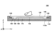
図2は、実施の形態の電子機器100を示す平面図であり、図3は、図2に示す電子機器100のA−A矢視断面を示す図である。なお、図2及び図3では、図示するように直交座標系であるXYZ座標系を定義する。
FIG. 2 is a plan view showing the
電子機器100は、筐体110、トップパネル120、両面テープ130、振動素子140、タッチパネル150、ディスプレイパネル160、基板170、LRA(Linear Resonant Actuator)180、及び圧力センサ190を含む。
The
筐体110は、例えば、樹脂製であり、図3に示すように凹部110Aに基板170、ディスプレイパネル160、及びタッチパネル150が配設されるとともに、両面テープ130によってトップパネル120が接着されている。
The
トップパネル120は、平面視で長方形の薄い平板状の部材であり、透明なガラス、又は、ポリカーボネートのような強化プラスティックで作製される。トップパネル120の表面(Z軸正方向側の面)は、電子機器100の利用者が操作入力を行う操作面の一例である。
The
トップパネル120は、Z軸負方向側の面に振動素子140が接着され、平面視における四辺が両面テープ130によって筐体110に接着されている。なお、両面テープ130は、トップパネル120の四辺を筐体110に接着できればよく、図3に示すように矩形環状である必要はない。
In the
トップパネル120のZ軸負方向側にはタッチパネル150が配設される。トップパネル120は、タッチパネル150の表面を保護するために設けられている。なお、トップパネル120の表面に、さらに別なパネル又は保護膜等が設けられていてもよい。
A
トップパネル120は、Z軸負方向側の面に振動素子140が接着された状態で、振動素子140が駆動されることによって振動する。実施の形態では、トップパネル120の固有振動周波数でトップパネル120を振動させて、トップパネル120に定在波を生じさせる。ただし、トップパネル120には振動素子140が接着されているため、実際には、振動素子140の重さ等を考慮した上で、固有振動周波数を決めることが好ましい。
The
振動素子140は、トップパネル120のZ軸負方向側の面において、Y軸正方向側において、X軸方向に伸延する短辺に沿って接着されている。振動素子140は、超音波帯の振動を発生できる素子であればよく、例えば、ピエゾ素子のような圧電素子を含むものを用いることができる。振動素子140は、第1振動素子又は振動素子の一例である。
The
振動素子140は、後述する駆動制御部から出力される駆動信号によって駆動される。振動素子140が発生する振動の振幅(強度)及び周波数は駆動信号によって設定される。また、振動素子140のオン/オフは駆動信号によって制御される。
The
なお、超音波帯とは、例えば、約20kHz以上の周波数帯をいう。実施の形態の電子機器100では、振動素子140が振動する周波数は、トップパネル120の振動数と等しくなるため、振動素子140は、トップパネル120の固有振動数で振動するように駆動信号によって駆動される。
In addition, an ultrasonic band means a frequency band about 20 kHz or more, for example. In the
タッチパネル150は、ディスプレイパネル160の上(Z軸正方向側)で、トップパネル120の下(Z軸負方向側)に配設されている。タッチパネル150は、電子機器100の利用者がトップパネル120に触れる位置(以下、操作入力の位置と称す)を検出する座標検出部の一例である。
The
タッチパネル150の下にあるディスプレイパネル160には、GUIによる様々なボタン等(以下、GUI操作部と称す)が表示される。このため、電子機器100の利用者は、通常、GUI操作部を操作するために、指先でトップパネル120に触れる。
On the
タッチパネル150は、利用者のトップパネル120への操作入力の位置を検出できる座標検出部であればよく、例えば、静電容量型又は抵抗膜型の座標検出部であればよい。ここでは、タッチパネル150が静電容量型の座標検出部である形態について説明する。タッチパネル150とトップパネル120との間に隙間があっても、静電容量型のタッチパネル150は、トップパネル120への操作入力を検出できる。
The
また、ここでは、タッチパネル150の入力面側にトップパネル120が配設される形態について説明するが、トップパネル120はタッチパネル150と一体的であってもよい。この場合、タッチパネル150の表面が図2及び図3に示すトップパネル120の表面になり、操作面を構築する。また、図2及び図3に示すトップパネル120を省いた構成であってもよい。この場合も、タッチパネル150の表面が操作面を構築する。また、この場合には、操作面を有する部材を、当該部材の固有振動で振動させればよい。
In addition, here, a form in which the
また、タッチパネル150が静電容量型の場合は、トップパネル120の上にタッチパネル150が配設されていてもよい。この場合も、タッチパネル150の表面が操作面を構築する。また、タッチパネル150が静電容量型の場合は、図2及び図3に示すトップパネル120を省いた構成であってもよい。この場合も、タッチパネル150の表面が操作面を構築する。また、この場合には、操作面を有する部材を、当該部材の固有振動で振動させればよい。
In the case where the
ディスプレイパネル160は、例えば、液晶ディスプレイパネル又は有機EL(Electroluminescence)パネル等の画像を表示できる表示部であればよい。ディスプレイパネル160は、筐体110の凹部110Aの内部で、図示を省略するホルダ等によって基板170の上(Z軸正方向側)に設置される。
The
ディスプレイパネル160は、後述するドライバIC(Integrated Circuit)によって駆動制御が行われ、電子機器100の動作状況に応じて、GUI操作部、画像、文字、記号、図形等を表示する。
The
基板170は、筐体110の凹部110Aの内部に配設される。基板170の上には、ディスプレイパネル160及びタッチパネル150が配設される。ディスプレイパネル160及びタッチパネル150は、図示を省略するホルダ等によって基板170及び筐体110に固定されている。
The
基板170には、後述する駆動制御装置の他に、電子機器100の駆動に必要な種々の回路等が実装される。
In addition to the drive control device described later, various circuits necessary for driving the
LRA180は、筐体110の凹部110Aに取り付けられている。本実施の形態では、LRA180は、可聴域の周波数の駆動信号によって駆動される。LRA180は、例えば、ボイスコイルを用いたLRAであっても良いし、圧電素子を用いたLRAであってもよい。LRA180は、第2振動素子の一例である。
The
LRA180は、可聴域の周波数の駆動信号で駆動され、可聴域の振動を発生させる振動デバイスであり、駆動信号の振幅により振動量が変化する。
The
圧力センサ190は、筐体110の凹部110Aに取り付けられ、利用者の操作入力によってトップパネル120にかかる圧力を検出する。圧力センサ190は、利用者の操作入力によってトップパネル120にかかる圧力を検出できるセンサであれば、どのようなセンサであってもよく、例えば、MEMS(Micro Electro Mechanical Systems)を用いたダイアフラムゲージ等を用いることができる。
The
圧力センサ190は、電子機器100の利用者が所定のGUIボタン等を押圧して入力を確定する操作を行うときに、GUIボタン等の押圧を検出するために設けられている。
The
以上のような構成の電子機器100は、トップパネル120に利用者の指が接触し、指先の移動を検出すると、基板170に実装される駆動制御部が振動素子140を駆動し、トップパネル120を超音波帯の周波数で振動させる。この超音波帯の周波数は、トップパネル120と振動素子140とを含む共振系の共振周波数であり、トップパネル120に定在波を発生させる。
In the
電子機器100は、超音波帯の定在波を発生させることにより、トップパネル120を通じて利用者に触感を提供する。
The
次に、図4を用いて、トップパネル120に発生させる定在波について説明する。
Next, standing waves generated in the
図4は、超音波帯の固有振動によってトップパネル120に生じる定在波のうち、トップパネル120の短辺に平行に形成される波頭を示す図であり、図4の(A)は側面図、(B)は斜視図である。図4の(A)、(B)では、図2及び図3と同様のXYZ座標を定義する。なお、図4の(A)、(B)では、理解しやすさのために、定在波の振幅を誇張して示す。また、図4の(A)、(B)では振動素子140を省略する。
FIG. 4 is a diagram showing a wave front formed in parallel to the short side of the
トップパネル120のヤング率E、密度ρ、ポアソン比δ、長辺寸法l、厚さtと、長辺方向に存在する定在波の周期数kとを用いると、トップパネル120の固有振動数(共振周波数)fは次式(1)、(2)で表される。定在波は1/2周期単位で同じ波形を有するため、周期数kは、0.5刻みの値を取り、0.5、1、1.5、2・・・となる。
When the Young's modulus E, density ρ, Poisson's ratio δ, long side dimension l, thickness t of the

図4の(A)、(B)に示す定在波は、一例として、周期数kが10の場合の波形である。例えば、トップパネル120として、長辺の長さlが140mm、短辺の長さが80mm、厚さtが0.7mmのGorilla(登録商標)ガラスを用いる場合には、周期数kが10の場合に、固有振動数fは33.5[kHz]となる。この場合は、周波数が33.5[kHz]の駆動信号を用いればよい。
The standing waves shown in FIGS. 4A and 4B are waveforms when the number of periods k is 10, as an example. For example, when the Gorilla (registered trademark) glass having a long side length l of 140 mm, a short side length of 80 mm, and a thickness t of 0.7 mm is used as the
トップパネル120は、平板状の部材であるが、振動素子140(図2及び図3参照)を駆動して超音波帯の固有振動を発生させると、図4の(A)、(B)に示すように撓むことにより、表面に定在波が生じる。
The
なお、ここでは、1つの振動素子140がトップパネル120のZ軸負方向側の面において、Y軸正方向側において、X軸方向に伸延する短辺に沿って接着される形態について説明するが、振動素子140を2つ用いてもよい。2つの振動素子140を用いる場合は、もう1つの振動素子140をトップパネル120のZ軸負方向側の面において、Y軸負方向側において、X軸方向に伸延する短辺に沿って接着すればよい。この場合に、2つの振動素子140は、トップパネル120の2つの短辺に平行な中心線を対称軸として、軸対称になるように配設すればよい。
Note that, here, a description will be given of a mode in which one
また、2つの振動素子140を駆動する場合は、周期数kが整数の場合は同一位相で駆動すればよく、周期数kが奇数の場合は逆位相で駆動すればよい。
In addition, when the two
次に、図5を用いて、電子機器100のトップパネル120に生じさせる超音波帯の固有振動について説明する。
Next, the natural vibration of the ultrasonic band generated in the
図5は、電子機器100のトップパネル120に生じさせる超音波帯の固有振動により、操作入力を行う指先に掛かる動摩擦力が変化する様子を説明する図である。図5の(A)、(B)では、利用者が指先でトップパネル120に触れながら、指をトップパネル120の奥側から手前側に矢印に沿って移動する操作入力を行っている。なお、振動のオン/オフは、振動素子140(図2及び図3参照)をオン/オフすることによって行われる。
FIG. 5 is a diagram illustrating a state in which the dynamic friction force applied to the fingertip that performs the operation input changes due to the natural vibration of the ultrasonic band generated in the
また、図5の(A)、(B)では、トップパネル120の奥行き方向において、振動がオフの間に指が触れる範囲をグレーで示し、振動がオンの間に指が触れる範囲を白く示す。
5A and 5B, in the depth direction of the
超音波帯の固有振動は、図4に示すようにトップパネル120の全体に生じるが、図5の(A)、(B)には、利用者の指がトップパネル120の奥側から手前側に移動する間に振動のオン/オフを切り替える動作パターンを示す。
The natural vibration of the ultrasonic band occurs in the entire
このため、図5の(A)、(B)では、トップパネル120の奥行き方向において、振動がオフの間に指が触れる範囲をグレーで示し、振動がオンの間に指が触れる範囲を白く示す。
For this reason, in FIGS. 5A and 5B, in the depth direction of the
図5の(A)に示す動作パターンでは、利用者の指がトップパネル120の奥側にあるときに振動がオフであり、指を手前側に移動させる途中で振動がオンになっている。
In the operation pattern shown in FIG. 5A, the vibration is turned off when the user's finger is on the back side of the
一方、図5の(B)に示す動作パターンでは、利用者の指がトップパネル120の奥側にあるときに振動がオンであり、指を手前側に移動させる途中で振動がオフになっている。
On the other hand, in the operation pattern shown in FIG. 5B, the vibration is turned on when the user's finger is on the back side of the
ここで、トップパネル120に超音波帯の固有振動を生じさせると、トップパネル120の表面と指との間にスクイーズ効果による空気層が介在し、指でトップパネル120の表面をなぞったときの動摩擦係数が低下する。
Here, when the natural vibration of the ultrasonic band is generated in the
従って、図5の(A)では、トップパネル120の奥側にグレーで示す範囲では、指先に掛かる動摩擦力は大きく、トップパネル120の手前側に白く示す範囲では、指先に掛かる動摩擦力は小さくなる。
Accordingly, in FIG. 5A, the dynamic friction force applied to the fingertip is large in the range indicated in gray on the back side of the
このため、図5の(A)に示すようにトップパネル120に操作入力を行う利用者は、振動がオンになると、指先に掛かる動摩擦力の低下を感知し、指先の滑り易さを知覚することになる。このとき、利用者はトップパネル120の表面がより滑らかになることにより、動摩擦力が低下するときに、トップパネル120の表面に凹部が存在するように感じる。
For this reason, as shown in FIG. 5A, the user who performs an operation input to the
一方、図5の(B)では、トップパネル120の奥前側に白く示す範囲では、指先に掛かる動摩擦力は小さく、トップパネル120の手前側にグレーで示す範囲では、指先に掛かる動摩擦力は大きくなる。
On the other hand, in FIG. 5B, the dynamic friction force applied to the fingertip is small in the range shown in white on the front side of the
このため、図5の(B)に示すようにトップパネル120に操作入力を行う利用者は、振動がオフになると、指先に掛かる動摩擦力の増大を感知し、指先の滑り難さ、あるいは、引っ掛かる感じを知覚することになる。そして、指先が滑りにくくなることにより、動摩擦力が高くなるときに、トップパネル120の表面に凸部が存在するように感じる。
For this reason, as shown in FIG. 5B, the user who performs an operation input to the
以上より、図5の(A)と(B)の場合に、利用者は指先で凹凸を感じ取ることができる。このように人間が凹凸の知覚することは、例えば、"触感デザインのための印刷物転写法とSticky-band Illusion"(第11回計測自動制御学会システムインテグレーション部門講演会論文集 (SI2010, 仙台)____174-177, 2010-12)に記載されている。また、"Fishbone Tactile Illusion"(日本バーチャルリアリティ学会第10 回大会論文集(2005 年9 月))にも記載されている。 From the above, in the case of FIGS. 5A and 5B, the user can feel the unevenness with the fingertip. Human perception of unevenness in this way is, for example, “Printed Transfer Method for Sticky Design and Sticky-band Illusion” (Proceedings of the 11th SICE System Integration Division Annual Conference (SI2010, Sendai) ___ 174 -177, 2010-12). It is also described in "Fishbone Tactile Illusion" (The 10th Annual Conference of the Virtual Reality Society of Japan (September 2005)).
なお、ここでは、振動のオン/オフを切り替える場合の動摩擦力の変化について説明したが、これは、振動素子140の振幅(強度)を変化させた場合も同様である。
Here, the change in the dynamic friction force when switching on / off the vibration has been described, but this is the same when the amplitude (intensity) of the
次に、図6を用いて、実施の形態の電子機器100の構成について説明する。また、ここでは、図6に加えて、図7を用いて、電子機器100の振動素子140を駆動する駆動波形について説明する。
Next, the configuration of the
図6は、実施の形態の電子機器100の構成を示す図である。
FIG. 6 is a diagram illustrating a configuration of the
電子機器100は、振動素子140、アンプ141、タッチパネル150、ドライバIC(Integrated Circuit)151、ディスプレイパネル160、ドライバIC161、LRA180、ドライバIC181、圧力センサ190、制御部200、正弦波発生器310、及び振幅変調器320を含む。
The
制御部200は、アプリケーションプロセッサ220、通信プロセッサ230、駆動制御部240、メモリ250、及びLRA駆動部260を有する。制御部200は、例えば、ICチップで実現される。
The
また、駆動制御部240、正弦波発生器310、及び振幅変調器320は、駆動制御装置300を構築する。なお、ここでは、アプリケーションプロセッサ220、通信プロセッサ230、駆動制御部240、メモリ250、及びLRA駆動部260が1つの制御部200によって実現される形態について説明するが、駆動制御部240は、制御部200の外部に別のICチップ又はプロセッサとして設けられていてもよい。この場合には、メモリ250に格納されているデータのうち、駆動制御部240の駆動制御に必要なデータは、メモリ250とは別のメモリに格納して、駆動制御装置300の内部に設ければよい。
In addition, the
また、同様に、LRA駆動部260は、制御部200の外部に別のICチップ又はプロセッサとして設けられていてもよい。この場合には、メモリ250に格納されているデータのうち、LRA駆動部260の駆動制御に必要なデータは、メモリ250とは別のメモリに格納して、駆動制御装置300の内部に設ければよい。
Similarly, the
図6では、筐体110、トップパネル120、両面テープ130、及び基板170(図2参照)は省略する。また、ここでは、アンプ141、ドライバIC151、ドライバIC161、駆動制御部240、メモリ250、LRA駆動部260、正弦波発生器310、及び振幅変調器320について説明する。
In FIG. 6, the
アンプ141は、駆動制御装置300と振動素子140との間に配設されており、駆動制御装置300から出力される駆動信号を増幅して振動素子140を駆動する。
The
ドライバIC151は、タッチパネル150に接続されており、タッチパネル150への操作入力があった位置を表す位置データを検出し、位置データを制御部200に出力する。この結果、位置データは、アプリケーションプロセッサ220と駆動制御部240に入力される。なお、位置データが駆動制御部240に入力されることは、位置データが駆動制御装置300に入力されることと等価である。
The
ドライバIC161は、ディスプレイパネル160に接続されており、駆動制御装置300から出力される描画データをディスプレイパネル160に入力し、描画データに基づく画像をディスプレイパネル160に表示させる。これにより、ディスプレイパネル160には、描画データに基づくGUI操作部又は画像等が表示される。
The
LRA180は、LRA駆動部260によって可聴域の周波数の駆動信号によって駆動される。LRA180は、可聴域の周波数の駆動信号で駆動され、可聴域の振動を発生させる振動デバイスであり、駆動信号の振幅により振動量が変化する。
The
ドライバIC181は、LRA駆動部260から入力される駆動信号をD/A(Digital to Analog)変換し、振幅等を増幅した信号をLRA180に出力する。
The
圧力センサ190は、電子機器100の利用者が所定のGUIボタン等を押圧して入力を確定する操作を行うときに、GUIボタン等の押圧を検出するために設けられている。入力を確定は、アプリケーションプロセッサ220が判定すればよい。
The
アプリケーションプロセッサ220は、電子機器100の種々のアプリケーションを実行する処理を行う。
The
通信プロセッサ230は、電子機器100が3G(Generation)、4G(Generation)、LTE(Long Term Evolution)、WiFi等の通信を行うために必要な処理を実行する。
The
駆動制御部240は、操作入力の有無と、操作入力の位置の移動距離とに応じて、振幅データを振幅変調器320に出力する。振幅データは、振動素子140の駆動に用いる駆動信号の強度を調整するための振幅値を表すデータである。
The
駆動制御部240は、所定の動作モードにおいて利用者がトップパネル120に触れると、ディスプレイパネル160に表示する所定のGUI操作部の位置と、トップパネル120への操作入力の位置との関係に応じて、トップパネル120に生じる固有振動の強弱が切り替わるように、振動素子140のオン/オフを切り替える。これは、トップパネル120の振動のオン/オフを切り替えると、利用者の指先に掛かる動摩擦力が変化するため、触感を通じて利用者に操作量を感知させるためである。
When the user touches the
駆動制御部240が振動素子140のオン/オフを切り替えると、利用者は指先で凹凸の触感を得る。振動素子140のオン/オフを切り替えることにより、利用者の指先に凹凸の触感を提供することができる。
When the
メモリ250は、動作モードの種類を表すデータ、着信の種類を表すデータ、及びターゲットとなるGUI操作部を表すデータを関連付けた制御データを格納する。
The
動作モードの種類を表すデータは、例えば、通常モード、及び、マナーモード等の動作モードの種類を表すデータである。マナーモードとは、電子機器100の着信音、及び、メールの受信音等を鳴らさずに、ディスプレイパネル160の表示、又は、LRA180の振動によって、着信又はメールの受信等を利用者に通知するモードである。通常モードは、電子機器100の着信音、及び、メールの受信音等を鳴らして利用者に着信又はメールの受信等を通知するモードである。
The data representing the type of operation mode is data representing the type of operation mode such as the normal mode and the manner mode, for example. The manner mode is a mode for notifying the user of the incoming call or the reception of the mail by the display of the
着信の種類を表すデータは、例えば、電話番号の非通知設定の相手からの着信、電話番号の通知設定の相手からの着信、特定のグループに含まれる相手からの着信、及び、特定のグループに含まれない相手からの着信等の種別を表すデータである。 The data indicating the type of incoming call may be, for example, an incoming call from a party whose phone number is not notified, an incoming call from a party whose phone number is set, an incoming call from a party included in a specific group, and a specific group. This is data representing the type of incoming call from a partner not included.
ターゲットとなるGUI操作部を表すデータは、GUI操作部の種類とGUI操作部の位置を表すデータを含む。ここで、ターゲットとなるGUI操作部とは、操作入力の位置に応じて駆動制御装置300がトップパネル120に超音波帯の固有振動を発生させることにより、利用者の指先を案内する案内目標となるGUI操作部をいう。駆動制御装置300は、利用者の指先をターゲットのGUI操作部の表示領域内に案内するために、操作入力の位置に応じてトップパネル120に固有振動を発生させる。
The data representing the target GUI operation unit includes data representing the type of the GUI operation unit and the position of the GUI operation unit. Here, the target GUI operation unit is a guide target that guides the user's fingertip by causing the
GUI操作部の種類を表すデータは、例えば、オンフックボタン、オフフックボタン、及び、その他の種々のアプリケーションで操作するボタン又はスライダー等の種類を表すデータである。GUI操作部の位置を表すデータは、ディスプレイパネル160にGUI操作部が表示される領域を座標で表すデータである。GUI操作部の位置を表すデータは、例えば、f1={(x,y)|f1(x,y)}というような式でGUI操作部が表示される領域を座標で表すデータである。
The data indicating the type of the GUI operation unit is, for example, data indicating the type of an on-hook button, an off-hook button, a button or a slider operated with various other applications, and the like. The data representing the position of the GUI operation unit is data representing, in coordinates, the area where the GUI operation unit is displayed on the
また、メモリ250は、アプリケーションプロセッサ220がアプリケーションの実行に必要とするデータ及びプログラム、及び、通信プロセッサ230が通信処理に必要とするデータ及びプログラム等を格納する。
In addition, the
LRA駆動部260は、利用者による操作入力の位置が、所定のGUI操作部の表示領域内にあるときに、LRA180を可聴域の周波数の駆動信号で駆動する。LRA駆動部260は、第2駆動制御部の一例である。LRA180は、LRA駆動部260によって可聴域の周波数の駆動信号で駆動され、可聴域の振動を発生させる。LRA180は、LRA駆動部260が出力する駆動信号の振幅により振動量が変化する。
The
正弦波発生器310は、トップパネル120を固有振動数で振動させるための駆動信号を生成するのに必要な正弦波を発生させる。例えば、トップパネル120を33.5[kHz]の固有振動数fで振動させる場合は、正弦波の周波数は、33.5[kHz]となる。正弦波発生器310は、超音波帯の正弦波信号を振幅変調器320に入力する。
The
振幅変調器320は、駆動制御部240から入力される振幅データを用いて、正弦波発生器310から入力される正弦波信号の振幅を変調して駆動信号を生成する。振幅変調器320は、正弦波発生器310から入力される超音波帯の正弦波信号の振幅のみを変調し、周波数及び位相は変調せずに、駆動信号を生成する。
The
このため、振幅変調器320が出力する駆動信号は、正弦波発生器310から入力される超音波帯の正弦波信号の振幅のみを変調した超音波帯の正弦波信号である。なお、振幅データがゼロの場合は、駆動信号の振幅はゼロになる。これは、振幅変調器320が駆動信号を出力しないことと等しい。
Therefore, the drive signal output from the
図7は、動作モードの種類を表すデータ、着信の種類を表すデータ、及びターゲットとなるGUI操作部を表すデータを関連付けた制御データを示す図である。 FIG. 7 is a diagram illustrating control data in which data representing the type of operation mode, data representing the type of incoming call, and data representing a GUI operation unit as a target are associated with each other.
動作モードの種類を表すデータは、例えば、通常モード、及び、マナーモード等の動作モードの種類を表すデータである。図7では、制御データの内容を分かり易くするために、動作モードの種類を表すデータを「通常モード」と「マナーモード」と記すが、実際のデータでは、「通常モード」と「マナーモード」を示すコードを用いればよい。 The data representing the type of operation mode is data representing the type of operation mode such as the normal mode and the manner mode, for example. In FIG. 7, in order to make the contents of the control data easy to understand, the data indicating the types of operation modes are described as “normal mode” and “manner mode”, but in the actual data, “normal mode” and “manner mode”. May be used.
ここで、マナーモードとは、例えば、電子機器100の着信音、及び、メールの受信音等を鳴らさずに、ディスプレイパネル160の表示、又は、LRA180の振動によって、着信又はメールの受信等を利用者に通知するモードである。また、通常モードは、例えば、マナーモードを解除した動作モードであり、電子機器100の着信音、及び、メールの受信音等を鳴らして利用者に着信又はメールの受信等を通知するモードである。
Here, the manner mode refers to, for example, the reception of an incoming call or mail by the display on the
着信の種類を表すデータは、例えば、電話番号の非通知設定の相手からの着信、電話番号の通知設定の相手からの着信、特定のグループに含まれる相手からの着信、及び、特定のグループに含まれない相手からの着信等の種別を表すデータである。 The data indicating the type of incoming call may be, for example, an incoming call from a party whose phone number is not notified, an incoming call from a party whose phone number is set, an incoming call from a party included in a specific group, and a specific group. This is data representing the type of incoming call from a partner not included.
図7では、制御データの内容を分かり易くするために、着信の種類を表すデータを「非通知」、「通知」、「特定グループ外」、「特定グループ」と記すが、実際のデータでは、「非通知」、「通知」、「特定グループ外」、「特定グループ」を示すコードを用いればよい。 In FIG. 7, in order to make the contents of the control data easy to understand, the data indicating the type of incoming call is described as “non-notification”, “notification”, “outside a specific group”, “specific group”. Codes indicating “not notify”, “notify”, “outside specific group”, and “specific group” may be used.
ターゲットとなるGUI操作部を表すデータは、GUI操作部の種類とGUI操作部の位置を表すデータを含む。GUI操作部の種類を表すデータは、例えば、オンフックボタン、オフフックボタン、及び、その他の種々のアプリケーションで操作するボタン又はスライダー等の種類を表すデータである。 The data representing the target GUI operation unit includes data representing the type of the GUI operation unit and the position of the GUI operation unit. The data indicating the type of the GUI operation unit is, for example, data indicating the type of an on-hook button, an off-hook button, a button or a slider operated with various other applications, and the like.
図7では、制御データの内容を分かり易くするために、ターゲットとなるGUI操作部を表すデータを「オフフックボタン」と「オンフックボタン」と記すが、実際のデータでは、「オフフックボタン」と「オンフックボタン」を示すコードを用いればよい。 In FIG. 7, in order to make the contents of the control data easy to understand, the data representing the target GUI operation unit is described as “off-hook button” and “on-hook button”, but in the actual data, “off-hook button” and “on-hook button”. A code indicating “button” may be used.
また、GUI操作部の位置を表すデータは、ディスプレイパネル160にGUI操作部が表示される領域を座標で表すデータである。GUI操作部の位置を表すデータは、例えば、f1={(x,y)|f1(x,y)}というような式でGUI操作部が表示される領域を座標で表すデータを用いればよい。GUI操作部の位置を表すデータは、対応するGUI操作部の種類を表すデータに関連付けておけばよい。
The data representing the position of the GUI operation unit is data representing, in coordinates, the area where the GUI operation unit is displayed on the
なお、図7に示す制御データは、一例であり、動作モードの種類を表すデータ、着信の種類を表すデータ、及びターゲットとなるGUI操作部を表すデータとして、図7に示すデータ以外のデータを含ませることができる。 Note that the control data shown in FIG. 7 is an example, and data other than the data shown in FIG. 7 is used as data representing the type of operation mode, data representing the type of incoming call, and data representing the target GUI operation unit. Can be included.
次に、図8のフローチャートを用いて、実施の形態の駆動制御装置300の駆動制御部240及びLRA駆動部260の制御処理について説明する。
Next, control processing of the
図8は、実施の形態の駆動制御装置300の駆動制御部240及びLRA駆動部260の制御処理を示すフローチャートである。図8に示す制御処理は、動作モードの種類に応じて、駆動制御部240とLRA駆動部260が連携して行う処理である。駆動制御部240とLRA駆動部260は、図7に示す制御データに基づいて、動作モードの種類に応じて、以下で説明するフローによる制御処理を実行する。
FIG. 8 is a flowchart illustrating control processing of the
また、図8に示す制御処理は、所定の制御周期毎に繰り返し実行される。ここで、所定の制御周期とは、例えば、電子機器100のOS(Operating System)が電子機器100を駆動するための制御を実行する周期である。
Further, the control process shown in FIG. 8 is repeatedly executed every predetermined control cycle. Here, the predetermined control cycle is, for example, a cycle in which an OS (Operating System) of the
駆動制御部240は、操作入力の位置が移動中であるかどうかを判定する(ステップS1)。駆動制御部240は、ドライバIC151から出力される位置データの変化に基づいて、操作入力の位置が移動中であるかどうかを判定すればよい。より具体的には、例えば、前回の制御周期におけるステップS1で取得した位置データと、今回の制御周期におけるステップS1で取得した位置データとが異なるかどうかによって、操作入力の位置が移動中であるかどうかを判定すればよい。
The
駆動制御部240は、操作入力の位置が移動中である(S1:YES)と判定すると、操作入力の位置がターゲットのGUI操作部に接近中であるかどうかを判定する(ステップS2)。駆動制御部240は、動作モードの種類に応じて制御データから得られるターゲットのGUI操作部の位置を表すデータと、移動中の操作入力の位置との位置関係に基づいて、操作入力の位置がターゲットのGUI操作部に接近中であるかどうかを判定すればよい。
If the
駆動制御部240は、ステップS2で操作入力の位置がターゲットのGUI操作部に接近中である(S2:YES)と判定した場合は、駆動信号をオンにして超音波帯での固有振動をトップパネル120に生じさせる(ステップS3)。超音波帯での固有振動をトップパネル120に生じさせると、スクイーズ効果による空気層が生じることにより、利用者の指先にかかる動摩擦係数が低下する。これにより、利用者の指先をターゲットのGUI操作部に案内する。
If the
駆動制御部240は、ステップS3で駆動信号をオンにして超音波帯での固有振動をトップパネル120に生じさせると、処理を終了する(エンド)。
When the drive signal is turned on in step S3 to cause the natural vibration in the ultrasonic band to occur in the
また、ステップS1で操作入力の位置が移動中ではない(S1:NO)と判定された場合であって、駆動信号をオンにしている場合は、駆動信号をオフにしてトップパネル120の超音波帯での固有振動をオフにする(ステップS4)。
If it is determined in step S1 that the position of the operation input is not moving (S1: NO) and the drive signal is turned on, the drive signal is turned off and the ultrasonic wave of the
ステップS1で操作入力の位置が移動中ではないと判定されるのは、例えば、操作入力の位置が停止している場合である。また、操作入力が行われていない場合も含めてもよい。操作入力の位置が停止している場合には、ターゲットのGUI操作部の表示領域内、又は、表示領域内の2つの場合があり得る。 In step S1, it is determined that the position of the operation input is not moving, for example, when the position of the operation input is stopped. Moreover, you may include the case where operation input is not performed. When the position of the operation input is stopped, there may be two cases in the display area of the target GUI operation unit or in the display area.
なお、駆動制御部240は、ステップS4において、前回の制御周期において駆動信号がオフにされている場合は、駆動信号をオフに維持する。
Note that if the drive signal is turned off in the previous control cycle in step S4, the
また、駆動制御部240は、ステップS2で操作入力の位置がターゲットのGUI操作部に接近中ではない(S2:NO)と判定した場合であって、駆動信号をオンにしている場合においても、駆動信号をオフにしてトップパネル120の超音波帯での固有振動をオフにする(ステップS4)。
Further, when the
ステップS2で操作入力の位置がターゲットのGUI操作部に接近中ではないと判定されるのは、例えば、操作入力の位置がターゲットのGUI操作部から離れる方向に移動している場合である。このようなケースには、ターゲットのGUI操作部に一度到達した指先がさらに移動して、ターゲットのGUI操作部を通り過ぎる場合も含まれる。 In step S2, it is determined that the operation input position is not approaching the target GUI operation unit, for example, when the operation input position is moving away from the target GUI operation unit. Such a case includes a case where the fingertip that has once reached the target GUI operation unit further moves and passes through the target GUI operation unit.
駆動制御部240は、操作入力の位置がターゲットのGUI操作部の表示領域内にあるかどうかを判定する(ステップS5)。操作入力の位置がターゲットのGUI操作部の表示領域内にあるかどうかは、動作モードの種類に応じて制御データから得られるターゲットのGUI操作部の位置を表すデータが表す領域内に、現在の制御周期で得られる位置データが表す位置(現在の操作入力の位置)が含まれるかどうかによって判定すればよい。
The
駆動制御部240は、操作入力の位置がターゲットのGUI操作部の表示領域内にあると判定した場合(S5:YES)は、LRA駆動部260にLRA180を駆動させることにより、可聴域の振動をトップパネル120に発生させる(ステップS6)。
If the
操作入力の位置がターゲットのGUI操作部の表示領域内にあるときは、利用者が指先でターゲットのGUI操作部に触れているときであるため、指先がターゲットのGUI操作部に到達したことを利用者に知らせるために、可聴域の振動をトップパネル120に発生させることとしたものである。
When the position of the operation input is within the display area of the target GUI operation unit, it is when the user is touching the target GUI operation unit with the fingertip, so that the fingertip has reached the target GUI operation unit. In order to notify the user, vibrations in the audible range are generated on the
可聴域の振動がトップパネル120に生じている状態では、超音波帯の振動が生じている状態とは異なり、スクイーズ効果による空気層は生じないため、超音波帯での固有振動がトップパネル120に生じている状態よりも利用者の指先にかかる動摩擦力は大きくなる。
In the state where the audible range vibration is generated in the
このため、操作入力の位置がターゲットのGUI操作部の表示領域内に到達した場合に可聴域の振動をトップパネル120に発生させることにより、指先がターゲットのGUI操作部に到達したことを利用者に触感を通じて知覚させることができる。
For this reason, when the position of the operation input reaches within the display area of the target GUI operation unit, the user hears that the fingertip has reached the target GUI operation unit by causing the
以上により、駆動制御部240は駆動制御を終了する(エンド)。
Thus, the
また、駆動制御部240は、操作入力の位置がターゲットのGUI操作部の表示領域内にないと判定した場合(S5:NO)は、駆動制御を終了する。ターゲットのGUI操作部の表示領域内に操作入力の位置がなければ、ステップS1にリターンして処理をやり直すためである。
If the
次に、図9乃至図14を用いて、実施の形態の電子機器100の動作例について説明する。
Next, an operation example of the
図9乃至図12は、実施の形態の電子機器100の動作例を示す図である。図9乃至図12では、図2乃至図4と同様のXYZ座標を定義する。また、図13及び図14は、実施の形態の電子機器100における振動のパターンを示す図である。
9 to 12 are diagrams illustrating an operation example of the
図9乃至図12では、一例として、電子機器100がスマートフォン端末機であって、マナーモードに設定されており、特定グループ外の人間から着信が生じる場合の動作について説明する。また、図9乃至図12には、GUI操作部として、オンフックボタン161とオフフックボタン162を示す。マナーモードでは、図7に示すように、ターゲットのGUI操作部は、オフフックボタン162となる。
9 to 12, as an example, an operation when the
図9に示すように、マナーモードに設定されており、特定グループ外の人間から着信が生じたときに、利用者の指先がターゲットのGUI操作部ではないオンフックボタン161に向かって矢印で示すように移動すると、トップパネル120に生じていた超音波帯の振動がオフにされる。これにより、利用者の指先にかかる動摩擦力は増大し、ターゲットのGUI操作部ではないオンフックボタン161に向かう指先の移動を行いにくい状態になる。図9には、指先にかかる動摩擦力は増大する様子を「ズズズ」という擬音で表現する。
As shown in FIG. 9, the manner mode is set, and when an incoming call occurs from a person outside the specific group, the user's fingertip is indicated by an arrow toward the on-
なお、これは、図8に示すフローチャートでは、スタート、S1:YES、S2:NO、S4、S5:NO、エンドの順で処理が行われるケースである。 In the flowchart shown in FIG. 8, this is a case where processing is performed in the order of start, S1: YES, S2: NO, S4, S5: NO, and end.
そして、図10に示すように、ターゲットのGUI操作部であるオフフックボタン162がある方向に利用者が指先を移動させると、トップパネル120に超音波帯の振動が発生し、利用者の指先は、オフフックボタン162に向かって移動し易い状態になる。このようにして、利用者の指先は、ターゲットのGUI操作部であるオフフックボタン162のある方向にツルっと滑り、オフフックボタン162に案内される。
Then, as shown in FIG. 10, when the user moves his / her fingertip in the direction where the off-
なお、これは、図8に示すフローチャートでは、スタート、S1:YES、S2:YES、S3、エンドの順で処理が行われるケースである。 In the flowchart shown in FIG. 8, this is a case where processing is performed in the order of start, S1: YES, S2: YES, S3, and end.
また、図11に示すように、利用者の指先がターゲットのGUI操作部であるオフフックボタン162に達して停止すると、トップパネル120に可聴域の振動を生じさせて、利用者に指先がオフフックボタン162に到達したことを触感で認識させる。図11には、可聴域の振動でブルブルとトップパネル120が振動する状態を示す。
Also, as shown in FIG. 11, when the user's fingertip reaches the off-
なお、図8に示すフローチャートでは、スタート、S1:NO、S4、S5:YES、S6、エンドの順で処理が行われるケースである。 In the flowchart shown in FIG. 8, the process is performed in the order of start, S1: NO, S4, S5: YES, S6, and end.
また、利用者の指先がターゲットのGUI操作部であるオフフックボタン162の表示領域内で止まらずに移動し続けている場合も、トップパネル120に可聴域の振動を生じさせて、利用者に指先がオフフックボタン162に到達したことを触感で認識させる。
Also, even when the user's fingertip continues to move without stopping within the display area of the off-
これは、図8に示すフローチャートでは、スタート、S1:YES、S2:NO、S4、S5:YES、S6、エンドの順で処理が行われるケースである。 In the flowchart shown in FIG. 8, processing is performed in the order of start, S1: YES, S2: NO, S4, S5: YES, S6, and end.
以上のように、実施の形態の駆動制御装置300によれば、操作入力の位置に応じてトップパネル120に生じさせる超音波帯の振動を制御することにより、利用者の指先をターゲットのGUI操作部に案内することができる。
As described above, according to the
また、図11に示すように、操作入力の位置が移動しながらオフフックボタン162に到達した場合に、オフフックボタン162で着信を拒否する際に、OSの種類によっては、一度指先をトップパネル120から離して、オフフックボタン162を押し直す必要が生じる場合がある。
Also, as shown in FIG. 11, when the off-
このような場合には、圧力センサ190(図3参照)を利用して、利用者がトップパネル120を押圧することによって操作の確定を行うようにしてもよい。
In such a case, the user may confirm the operation by pressing the
また、図9に示す状態から、利用者が指先をさらにオンフックボタン161に向けて移動させて、図12に示すように、指先がオンフックボタン161に到達した場合には、超音波帯の振動を生じさせてもよい。
In addition, when the user further moves the fingertip toward the on-
このようにすれば、利用者の指先にかかる動摩擦力を低減することができるので、利用者の指先をツルっと滑らせて、オンフックボタン161を操作させることなく、通過させることができる。
In this way, the dynamic frictional force applied to the user's fingertip can be reduced, so that the user's fingertip can be slipped and passed without operating the on-
このような制御処理は、例えば、ターゲットのGUI操作部ではないGUI操作部であるオンフックボタン161の表示領域を制御データに組み込み、操作入力の位置がオンフックボタン161の内部にあるときに、超音波帯の振動をトップパネル120に生じさせるように駆動制御装置300が駆動制御を行えばよい。
Such control processing is performed by, for example, incorporating the display area of the on-
次に、図13及び図14を用いて、電子機器100の振動素子140とLRA180の駆動パターンについて説明する。
Next, drive patterns of the
図13は、電子機器100の振動素子140とLRA180を駆動する駆動波形を示す図である。図14は、電子機器100の振動素子140を駆動する駆動波形を示す図である。図13において、横軸は時間を表し、縦軸は振動素子140又はLRA180を振動させる駆動信号が表す振幅を示す。また、図14において、横軸は時間を表し、縦軸は振動素子140を振動させる駆動信号が表す振幅を示す。なお、ターゲットのGUI操作部は、オフフックボタン162に設定されているものとする。
FIG. 13 is a diagram illustrating a driving waveform for driving the
図13に示すように、時刻t1で操作入力が行われ、時刻t1からt2にかけて、操作入力の位置がターゲットのGUI操作部であるオフフックボタン162に接近しない方向に移動したとする。この場合、時刻t1からt2までは、駆動制御部240が出力する駆動信号の振幅がゼロに設定され、振動素子140は駆動されず、トップパネル120に振動は生じない。
As shown in FIG. 13, it is assumed that an operation input is performed at time t1, and the position of the operation input moves in a direction not approaching the off-
また、時刻t2で操作入力の位置がオフフックボタン162に接近する方向に切り替わり、時刻t2からt3まで操作入力の位置が移動したとする。この場合、時刻t2からt3までは、駆動制御部240が出力する駆動信号の振幅が所定値に設定され、振動素子140が超音波帯の振動信号で駆動され、トップパネル120に超音波帯の振動が生じる。
Further, it is assumed that the position of the operation input is switched to a direction approaching the off-
そして、時刻t3で操作入力の位置がオフフックボタン162に達すると、駆動制御部240が出力する駆動信号の振幅がゼロになり、LRA駆動部260が出力する駆動信号による可聴域の周波数の駆動信号によってLRA180が駆動され、トップパネル120に可聴域の周波数の振動が生じる。
When the position of the operation input reaches the off-
このため、時刻t4で利用者の指先がトップパネル120から離れるまで、可聴域の周波数による駆動信号によってLRA180が駆動される。
For this reason, the
以上のような動作により、利用者の指先は、ターゲットのGUI操作部であるオフフックボタン162に案内され、オフフックボタン162に到達したときに振動の種類が切り替わることにより、利用者は触感だけで、オフフックボタン162を操作することができる。
By the operation as described above, the user's fingertip is guided to the off-
また、図13では、操作入力の位置がオフフックボタン162に達したときに、可聴域の周波数の駆動信号によってLRA180が駆動され、トップパネル120に可聴域の周波数の振動が生じる駆動パターンを示すが、可聴域の周波数の振動を発生させる代わりに、図14に示すように、超音波帯の振動のパターンを変えるようにしてもよい。
FIG. 13 shows a driving pattern in which when the position of the operation input reaches the off-
図14では、超音波帯の駆動信号で振動素子140を一定間隔で断続的に駆動する駆動パターンを示す。このような駆動パターンの振動を図13の時刻t3からt4の間の可聴域の周波数の振動の代わりに用いることにより、超音波帯の振動によって指先がオフフックボタン162に到達したことを利用者に認識させることができる。
FIG. 14 shows a drive pattern in which the
なお、このような場合には、電子機器100がLRA180とLRA駆動部260を含まない構成にすることができる。
In such a case, the
以上、実施の形態の電子機器100によれば、利用者による操作入力の位置に応じて、トップパネル120の超音波帯の固有振動を発生させて利用者の指先に掛かる動摩擦力を変化させるので、利用者が操作入力を行うべき位置がある方向を容易に認識可能な良好な触感を提供することができる。
As described above, according to the
すなわち、良好な触感を提供することにより利用者が操作入力を行うべき位置がある方向を容易に認識できる駆動制御装置300、電子機器100、及び駆動制御方法を提供することができる。
That is, it is possible to provide the
また、実施の形態の電子機器100は、正弦波発生器310で発生される超音波帯の正弦波の振幅のみを振幅変調器320で変調することによって駆動信号を生成している。正弦波発生器310で発生される超音波帯の正弦波の周波数は、トップパネル120の固有振動数に等しく、また、この固有振動数は振動素子140を加味して設定している。
In addition,
すなわち、正弦波発生器310で発生される超音波帯の正弦波の周波数又は位相を変調することなく、振幅のみを振幅変調器320で変調することによって駆動信号を生成している。
That is, the drive signal is generated by modulating only the amplitude by the
従って、トップパネル120の超音波帯の固有振動をトップパネル120に発生させることができ、スクイーズ効果による空気層の介在を利用して、指でトップパネル120の表面をなぞったときの動摩擦係数を確実に低下させることができる。また、Sticky-band Illusion効果、又は、Fishbone Tactile Illusion効果により、トップパネル120の表面に凹凸が存在するような良好な触感を利用者に提供することができる。
Therefore, the natural vibration of the ultrasonic band of the
また、以上では、トップパネル120に凹凸が存在するような触感を利用者に提供するために、振動素子140のオン/オフを切り替える形態について説明した。振動素子140をオフにするとは、振動素子140を駆動する駆動信号が表す振幅値をゼロにすることである。
In the above description, the mode in which the
しかしながら、このような触感を提供するために、必ずしも振動素子140をオンからオフにする必要はない。例えば、振動素子140のオフの状態の代わりに、振幅を小さくして振動素子140を駆動する状態を用いてもよい。例えば、振幅を1/5程度に小さくすることにより、振動素子140をオンからオフにする場合と同様に、トップパネル120に凹凸が存在するような触感を利用者に提供してもよい。
However, in order to provide such a tactile sensation, the
この場合は、振動素子140の振動の強弱を切り替えるような駆動信号で振動素子140を駆動することになる。この結果、トップパネル120に発生する固有振動の強弱が切り替えられ、利用者の指先に凹凸が存在するような触感を提供することができる。
In this case, the
振動素子140の振動の強弱を切り替えるために、振動を弱くする際に振動素子140をオフにすると、振動素子140のオン/オフを切り替えることになる。振動素子140のオン/オフを切り替えることは、振動素子140を断続的に駆動することである。
If the
以上、実施の形態によれば、良好な触感を提供できる電子機器100、及び駆動制御方法を提供することができる。
As described above, according to the embodiment, it is possible to provide the
以上、本発明の例示的な実施の形態の駆動制御装置、電子機器、及び駆動制御方法について説明したが、本発明は、具体的に開示された実施の形態に限定されるものではなく、特許請求の範囲から逸脱することなく、種々の変形や変更が可能である。 The drive control device, the electronic apparatus, and the drive control method according to the exemplary embodiments of the present invention have been described above. However, the present invention is not limited to the specifically disclosed embodiments, and may be patented. Various modifications and changes can be made without departing from the scope of the claims.
100 電子機器
110 筐体
120 トップパネル
130 両面テープ
140 振動素子
150 タッチパネル
160 ディスプレイパネル
170 基板
180 LRA
190 圧力センサ
200 制御部
220 アプリケーションプロセッサ
230 通信プロセッサ
240 駆動制御部
250 メモリ
260 駆動制御部
300 駆動制御装置
310 正弦波発生器
320 振幅変調器DESCRIPTION OF
190
Claims (11)
前記操作面に超音波帯の固有振動を生成する超音波帯の波信号の振幅を、前記第1振動素子の駆動に用いる駆動信号の振幅を表す振幅データに応じて変調し、変調された波信号を前記駆動信号として前記第1振動素子に出力する振幅変調器と、
前記波信号の振幅の変調に用いられる前記振幅データを前記振幅変調器に出力し、前記振幅データに応じて前記第1振動素子を駆動する第1駆動制御部であって、前記表示部に表示する所定のGUI操作部の位置と、前記操作面への操作入力の位置との関係に応じて、前記固有振動の強弱が切り替わるように前記振幅データを制御する、第1駆動制御部を含む駆動制御装置。 A display unit, a top panel disposed on a display surface side of the display unit and having an operation surface, a position detection unit for detecting a position of an operation input performed on the operation surface, and generating vibration on the operation surface A drive control device for driving the first vibration element of an electronic device including the first vibration element,
The amplitude of the wave signal of the ultrasonic band that generates the natural vibration of the ultrasonic band on the operation surface is modulated according to amplitude data representing the amplitude of the drive signal used for driving the first vibration element, and the modulated wave An amplitude modulator that outputs a signal to the first vibration element as the drive signal;
A first drive control unit that outputs the amplitude data used for modulating the amplitude of the wave signal to the amplitude modulator and drives the first vibration element according to the amplitude data, and displays on the display unit A drive including a first drive control unit that controls the amplitude data so that the intensity of the natural vibration is switched according to a relationship between a position of a predetermined GUI operation unit to be operated and a position of an operation input to the operation surface; Control device.
前記表示部の表示面側に配設され、操作面を有するトップパネルと、
前記操作面に行われる操作入力の位置を検出する位置検出部と、
前記操作面に振動を発生させる振動素子と、
前記操作面に超音波帯の固有振動を生成する超音波帯の波信号の振幅を、前記振動素子の駆動に用いる駆動信号の振幅を表す振幅データに応じて変調し、変調された波信号を前記駆動信号として前記振動素子に出力する振幅変調器と、
前記波信号の振幅の変調に用いられる前記振幅データを前記振幅変調器に出力し、前記振幅データに応じて前記振動素子を駆動する駆動制御部であって、前記表示部に表示する所定のGUI操作部の位置と、前記操作面への操作入力の位置との関係に応じて、前記固有振動の強弱が切り替わるように前記振幅データを制御する、駆動制御部と
を含む電子機器。 A display unit;
A top panel disposed on the display surface side of the display unit and having an operation surface;
A position detection unit for detecting a position of an operation input performed on the operation surface;
A vibration element for generating vibration on the operation surface;
The amplitude of the wave signal of the ultrasonic band that generates the natural vibration of the ultrasonic band on the operation surface is modulated according to amplitude data representing the amplitude of the drive signal used for driving the vibration element, and the modulated wave signal is An amplitude modulator that outputs the drive signal to the vibration element;
A drive control unit that outputs the amplitude data used for modulating the amplitude of the wave signal to the amplitude modulator and drives the vibration element according to the amplitude data, and is a predetermined GUI displayed on the display unit An electronic device comprising: a drive control unit that controls the amplitude data so that the intensity of the natural vibration is switched according to a relationship between a position of an operation unit and a position of an operation input to the operation surface.
前記所定のGUI操作部は、所定の動作モードにおいて利用者が操作を行うGUI操作部として前記制御データに含まれており、
前記駆動制御部は、前記固有振動の強弱の切り替えによって前記所定のGUI操作部に利用者の指先を案内するように前記振動素子を駆動する、請求項8記載の電子機器。 A memory for storing control data in which first identification data for identifying the predetermined GUI operation unit and second identification data representing a predetermined operation mode for displaying the predetermined GUI operation unit on the display unit are associated with each other; Including
The predetermined GUI operation unit is included in the control data as a GUI operation unit operated by a user in a predetermined operation mode,
The electronic device according to claim 8, wherein the drive control unit drives the vibration element so as to guide a user's fingertip to the predetermined GUI operation unit by switching the strength of the natural vibration.
前記振幅変調器が、前記操作面に超音波帯の固有振動を生成する超音波帯の波信号の振幅を、前記振動素子の駆動に用いる駆動信号の振幅を表す振幅データに応じて変調し、変調された波信号を前記駆動信号として前記振動素子に出力し、
前記コンピュータが、前記波信号の振幅の変調に用いられる前記振幅データを前記振幅変調器に出力し、前記振幅データに応じて前記振動素子を駆動する際に、前記表示部に表示する所定のGUI操作部の位置と、前記操作面への操作入力の位置との関係に応じて、前記固有振動の強弱が切り替わるように前記振幅データを制御する、駆動制御方法。 A display unit, a top panel disposed on a display surface side of the display unit and having an operation surface, a position detection unit for detecting a position of an operation input performed on the operation surface, and generating vibration on the operation surface A drive control method for driving the vibration element of an electronic device including a vibration element, an amplitude modulator, and a computer,
The amplitude modulator modulates the amplitude of the wave signal of the ultrasonic band that generates the natural vibration of the ultrasonic band on the operation surface according to amplitude data representing the amplitude of the drive signal used to drive the vibration element; The modulated wave signal is output to the vibration element as the drive signal,
A predetermined GUI displayed on the display unit when the computer outputs the amplitude data used for modulating the amplitude of the wave signal to the amplitude modulator and drives the vibration element in accordance with the amplitude data. A drive control method for controlling the amplitude data so that the intensity of the natural vibration is switched according to a relationship between a position of an operation unit and a position of an operation input to the operation surface.
Applications Claiming Priority (1)
| Application Number | Priority Date | Filing Date | Title |
|---|---|---|---|
| PCT/JP2013/076079 WO2015045064A1 (en) | 2013-09-26 | 2013-09-26 | Drive control apparatus, electronic device, and drive control method |
Publications (2)
| Publication Number | Publication Date |
|---|---|
| JPWO2015045064A1 JPWO2015045064A1 (en) | 2017-03-02 |
| JP6172284B2 true JP6172284B2 (en) | 2017-08-02 |
Family
ID=52742268
Family Applications (1)
| Application Number | Title | Priority Date | Filing Date |
|---|---|---|---|
| JP2015538705A Active JP6172284B2 (en) | 2013-09-26 | 2013-09-26 | Drive control apparatus, electronic device, and drive control method |
Country Status (4)
| Country | Link |
|---|---|
| US (1) | US20160202764A1 (en) |
| JP (1) | JP6172284B2 (en) |
| CN (1) | CN105593792B (en) |
| WO (1) | WO2015045064A1 (en) |
Cited By (1)
| Publication number | Priority date | Publication date | Assignee | Title |
|---|---|---|---|---|
| KR20190058111A (en) * | 2017-11-21 | 2019-05-29 | 삼성전자주식회사 | Method and apparatus for providing vibration |
Families Citing this family (14)
| Publication number | Priority date | Publication date | Assignee | Title |
|---|---|---|---|---|
| JP6010012B2 (en) * | 2013-12-03 | 2016-10-19 | 富士フイルム株式会社 | Conductive sheet, capacitive touch panel and display device |
| JPWO2015121955A1 (en) * | 2014-02-14 | 2017-03-30 | 富士通株式会社 | Electronic device, input device, and drive control method |
| US20170060241A1 (en) * | 2015-08-26 | 2017-03-02 | Fujitsu Ten Limited | Input device, display device, method of controlling input device, and program |
| JP2017045251A (en) * | 2015-08-26 | 2017-03-02 | 富士通テン株式会社 | Input device, display device, control method and program of input device |
| CN108475116B (en) * | 2016-01-08 | 2021-06-22 | 富士通株式会社 | Electronic device and driving method of electronic device |
| KR102496410B1 (en) * | 2016-03-25 | 2023-02-06 | 삼성전자 주식회사 | Electronic apparatus and method for outputting sound thereof |
| JP2018072951A (en) * | 2016-10-25 | 2018-05-10 | 株式会社東海理化電機製作所 | Manipulation device |
| JP2018097635A (en) * | 2016-12-14 | 2018-06-21 | 株式会社東海理化電機製作所 | Tactile sense presentation device |
| JP6852795B2 (en) * | 2017-09-11 | 2021-03-31 | 富士通株式会社 | Control devices, electronic devices, and control methods for electronic devices |
| WO2019092821A1 (en) * | 2017-11-08 | 2019-05-16 | 富士通株式会社 | Drive control device, electronic device, and drive control method |
| JP6904222B2 (en) * | 2017-11-08 | 2021-07-14 | 富士通株式会社 | Drive control device, electronic device, and drive control method |
| US10748389B2 (en) * | 2018-06-15 | 2020-08-18 | Immersion Corporation | Damping for a haptic actuator |
| KR20200068341A (en) * | 2018-12-05 | 2020-06-15 | 엘지디스플레이 주식회사 | Display apparatus |
| US11681373B1 (en) * | 2021-12-08 | 2023-06-20 | International Business Machines Corporation | Finger movement management with haptic feedback in touch-enabled devices |
Family Cites Families (12)
| Publication number | Priority date | Publication date | Assignee | Title |
|---|---|---|---|---|
| JP3888099B2 (en) * | 2001-08-17 | 2007-02-28 | 富士ゼロックス株式会社 | Touch panel device |
| JP4875050B2 (en) * | 2008-12-09 | 2012-02-15 | 京セラ株式会社 | Input device |
| JP2010211509A (en) * | 2009-03-10 | 2010-09-24 | Ricoh Co Ltd | Input device and image forming device |
| JP5343871B2 (en) * | 2009-03-12 | 2013-11-13 | 株式会社リコー | Touch panel device, display device with touch panel including the same, and control method for touch panel device |
| GB2474047B (en) * | 2009-10-02 | 2014-12-17 | New Transducers Ltd | Touch sensitive device |
| JP5668076B2 (en) * | 2009-11-17 | 2015-02-12 | イマージョン コーポレーションImmersion Corporation | System and method for increasing haptic bandwidth in electronic devices |
| US9417695B2 (en) * | 2010-04-08 | 2016-08-16 | Blackberry Limited | Tactile feedback method and apparatus |
| KR101740436B1 (en) * | 2010-12-08 | 2017-05-26 | 엘지전자 주식회사 | Mobile terminal and method for controlling thereof |
| WO2012125924A2 (en) * | 2011-03-17 | 2012-09-20 | Coactive Drive Corporation | Asymmetric and general vibration waveforms from multiple synchronized vibration actuators |
| JP5689362B2 (en) * | 2011-05-23 | 2015-03-25 | 株式会社東海理化電機製作所 | Input device |
| US20130113760A1 (en) * | 2011-11-07 | 2013-05-09 | Google Inc. | Techniques for providing localized tactile feedback to a user via an electro-acoustic touch display of a user device |
| JP6008331B2 (en) * | 2012-02-03 | 2016-10-19 | パナソニックIpマネジメント株式会社 | Tactile sensation presentation apparatus, tactile sensation presentation apparatus driving method, and driving program |
-
2013
- 2013-09-26 CN CN201380079874.4A patent/CN105593792B/en active Active
- 2013-09-26 WO PCT/JP2013/076079 patent/WO2015045064A1/en active Application Filing
- 2013-09-26 JP JP2015538705A patent/JP6172284B2/en active Active
-
2016
- 2016-03-23 US US15/078,640 patent/US20160202764A1/en not_active Abandoned
Cited By (3)
| Publication number | Priority date | Publication date | Assignee | Title |
|---|---|---|---|---|
| KR20190058111A (en) * | 2017-11-21 | 2019-05-29 | 삼성전자주식회사 | Method and apparatus for providing vibration |
| US11262845B2 (en) | 2017-11-21 | 2022-03-01 | Samsung Electronics Co., Ltd. | Device and method for providing vibration |
| KR102462204B1 (en) * | 2017-11-21 | 2022-11-02 | 삼성전자주식회사 | Method and apparatus for providing vibration |
Also Published As
| Publication number | Publication date |
|---|---|
| CN105593792A (en) | 2016-05-18 |
| US20160202764A1 (en) | 2016-07-14 |
| WO2015045064A1 (en) | 2015-04-02 |
| CN105593792B (en) | 2019-04-23 |
| JPWO2015045064A1 (en) | 2017-03-02 |
Similar Documents
| Publication | Publication Date | Title |
|---|---|---|
| JP6172284B2 (en) | Drive control apparatus, electronic device, and drive control method | |
| JP5780368B1 (en) | Drive control apparatus, electronic device, and drive control method | |
| JP5584775B2 (en) | Electronic device and portable terminal equipped with the same | |
| JP4177142B2 (en) | Coordinate input device and drive device | |
| WO2015045063A1 (en) | Drive control apparatus, electronic device, and drive control method | |
| JP2010238222A (en) | Touch panel device, touch panel-equipped display device including the same and control method for the touch panel device | |
| JP2008123429A (en) | Touch panel display device, electronic equipment and game machine | |
| WO2015136923A1 (en) | Electronic device | |
| JPWO2012063645A1 (en) | Electronic device and portable terminal equipped with the same | |
| JPWO2016163000A1 (en) | Drive control apparatus, electronic device, drive control program, and drive control method | |
| JPWO2016157491A1 (en) | Electronic device, coordinate detection unit, and adhesive member | |
| JP2012068823A (en) | Display device with input function | |
| JP6123850B2 (en) | Drive control apparatus, electronic device, and drive control method | |
| US10664056B2 (en) | Control device, input system and control method | |
| JP2015207242A (en) | Electronic equipment | |
| US11086435B2 (en) | Drive control device, electronic device, and drive control method | |
| US20200142492A1 (en) | Haptic effects using a high bandwidth thin actuation system | |
| JP2016207128A (en) | Input device, and electronic apparatus | |
| WO2013186841A1 (en) | Electronic device and vibration provision method | |
| KR20130025759A (en) | Haptic apparatus using a waveform generator and control method thereof | |
| JP2013242807A (en) | Electronic apparatus | |
| WO2016092644A1 (en) | Electronic device and drive control method | |
| JP2012203552A (en) | Input device, display device, and portable terminal | |
| JP2013242803A (en) | Electronic apparatus | |
| JP6904222B2 (en) | Drive control device, electronic device, and drive control method |
Legal Events
| Date | Code | Title | Description |
|---|---|---|---|
| A521 | Written amendment |
Free format text: JAPANESE INTERMEDIATE CODE: A523 Effective date: 20161130 |
|
| A131 | Notification of reasons for refusal |
Free format text: JAPANESE INTERMEDIATE CODE: A131 Effective date: 20170314 |
|
| A521 | Written amendment |
Free format text: JAPANESE INTERMEDIATE CODE: A523 Effective date: 20170509 |
|
| TRDD | Decision of grant or rejection written | ||
| A01 | Written decision to grant a patent or to grant a registration (utility model) |
Free format text: JAPANESE INTERMEDIATE CODE: A01 Effective date: 20170606 |
|
| A61 | First payment of annual fees (during grant procedure) |
Free format text: JAPANESE INTERMEDIATE CODE: A61 Effective date: 20170619 |
|
| R150 | Certificate of patent or registration of utility model |
Ref document number: 6172284 Country of ref document: JP Free format text: JAPANESE INTERMEDIATE CODE: R150 |