JP6172265B2 - Vehicle window glass and antenna - Google Patents
Vehicle window glass and antenna Download PDFInfo
- Publication number
- JP6172265B2 JP6172265B2 JP2015508701A JP2015508701A JP6172265B2 JP 6172265 B2 JP6172265 B2 JP 6172265B2 JP 2015508701 A JP2015508701 A JP 2015508701A JP 2015508701 A JP2015508701 A JP 2015508701A JP 6172265 B2 JP6172265 B2 JP 6172265B2
- Authority
- JP
- Japan
- Prior art keywords
- slot
- conductive film
- film
- window glass
- glass plate
- Prior art date
- Legal status (The legal status is an assumption and is not a legal conclusion. Google has not performed a legal analysis and makes no representation as to the accuracy of the status listed.)
- Active
Links
Images


Classifications
-
- H—ELECTRICITY
- H01—ELECTRIC ELEMENTS
- H01Q—ANTENNAS, i.e. RADIO AERIALS
- H01Q1/00—Details of, or arrangements associated with, antennas
- H01Q1/27—Adaptation for use in or on movable bodies
- H01Q1/32—Adaptation for use in or on road or rail vehicles
- H01Q1/325—Adaptation for use in or on road or rail vehicles characterised by the location of the antenna on the vehicle
-
- H—ELECTRICITY
- H01—ELECTRIC ELEMENTS
- H01Q—ANTENNAS, i.e. RADIO AERIALS
- H01Q1/00—Details of, or arrangements associated with, antennas
- H01Q1/12—Supports; Mounting means
- H01Q1/1271—Supports; Mounting means for mounting on windscreens
- H01Q1/1278—Supports; Mounting means for mounting on windscreens in association with heating wires or layers
-
- H—ELECTRICITY
- H01—ELECTRIC ELEMENTS
- H01Q—ANTENNAS, i.e. RADIO AERIALS
- H01Q1/00—Details of, or arrangements associated with, antennas
- H01Q1/12—Supports; Mounting means
- H01Q1/1271—Supports; Mounting means for mounting on windscreens
- H01Q1/1285—Supports; Mounting means for mounting on windscreens with capacitive feeding through the windscreen
-
- H—ELECTRICITY
- H01—ELECTRIC ELEMENTS
- H01Q—ANTENNAS, i.e. RADIO AERIALS
- H01Q13/00—Waveguide horns or mouths; Slot antennas; Leaky-waveguide antennas; Equivalent structures causing radiation along the transmission path of a guided wave
- H01Q13/10—Resonant slot antennas
-
- H—ELECTRICITY
- H01—ELECTRIC ELEMENTS
- H01Q—ANTENNAS, i.e. RADIO AERIALS
- H01Q13/00—Waveguide horns or mouths; Slot antennas; Leaky-waveguide antennas; Equivalent structures causing radiation along the transmission path of a guided wave
- H01Q13/10—Resonant slot antennas
- H01Q13/106—Microstrip slot antennas
-
- H—ELECTRICITY
- H01—ELECTRIC ELEMENTS
- H01Q—ANTENNAS, i.e. RADIO AERIALS
- H01Q13/00—Waveguide horns or mouths; Slot antennas; Leaky-waveguide antennas; Equivalent structures causing radiation along the transmission path of a guided wave
- H01Q13/10—Resonant slot antennas
- H01Q13/16—Folded slot antennas
-
- H—ELECTRICITY
- H01—ELECTRIC ELEMENTS
- H01Q—ANTENNAS, i.e. RADIO AERIALS
- H01Q9/00—Electrically-short antennas having dimensions not more than twice the operating wavelength and consisting of conductive active radiating elements
- H01Q9/04—Resonant antennas
- H01Q9/16—Resonant antennas with feed intermediate between the extremities of the antenna, e.g. centre-fed dipole
-
- H—ELECTRICITY
- H01—ELECTRIC ELEMENTS
- H01Q—ANTENNAS, i.e. RADIO AERIALS
- H01Q5/00—Arrangements for simultaneous operation of antennas on two or more different wavebands, e.g. dual-band or multi-band arrangements
- H01Q5/30—Arrangements for providing operation on different wavebands
- H01Q5/378—Combination of fed elements with parasitic elements
- H01Q5/385—Two or more parasitic elements
Description
本発明は、スロットを有するアンテナ及び該アンテナを備えた車両用窓ガラスに関する。 The present invention relates to an antenna having a slot and a vehicle window glass including the antenna.
車両用窓ガラスに導電膜が設けられ、該導電膜にスロットを形成させてアンテナとして機能させる車両用窓ガラスが知られている(例えば、特許文献1を参照)。特許文献1に開示されたアンテナは、一対の電極がガラス板を挟んで導電膜に対向して設けられ、一対の電極を導電膜に投影すると、導電膜に形成されたスロットが一対の電極に挟まれるように配置され、一対の電極と導電膜とを容量結合させる構成を有している。特許文献1により、車両用窓ガラスに導電膜が形成されることで従来の線状導体アンテナを設置するスペースがないような場合でも所望の電波を受信できる。 A vehicle window glass is known in which a conductive film is provided on a vehicle window glass and a slot is formed in the conductive film to function as an antenna (see, for example, Patent Document 1). In the antenna disclosed in Patent Document 1, a pair of electrodes is provided to face a conductive film with a glass plate interposed therebetween, and when the pair of electrodes is projected onto the conductive film, a slot formed in the conductive film becomes a pair of electrodes. It is arranged so as to be sandwiched, and has a configuration in which a pair of electrodes and a conductive film are capacitively coupled. According to Patent Document 1, a desired radio wave can be received even when there is no space for installing a conventional linear conductor antenna by forming a conductive film on a vehicle window glass.
しかしながら、車両用窓ガラスに設置されるアンテナは、様々な環境に対応できるような高いアンテナ利得を有することが求められており、特許文献1のような導電膜を利用したアンテナにおいても、さらなるアンテナ利得の向上が求められている。本発明は、高いアンテナ利得を有する、アンテナ及びアンテナを備えた車両用窓ガラスの提供を目的とする。 However, the antenna installed on the window glass for a vehicle is required to have a high antenna gain that can cope with various environments. Even in an antenna using a conductive film as in Patent Document 1, a further antenna is required. There is a need for improved gain. An object of this invention is to provide the window glass for vehicles provided with the antenna and antenna which have a high antenna gain.
上記目的を達成するため、本発明は、ガラス板と、誘電体と、前記ガラス板と前記誘電体との間に設けられた電熱膜とを備え、前記電熱膜は、導電膜と、前記導電膜よりも低抵抗の帯状電極とを備え、前記帯状電極は、前記導電膜の外縁の少なくとも対向する二辺に沿って配置され且つ前記導電膜と直流的に接続され、前記導電膜が前記帯状電極を介して通電可能に構成される車両用窓ガラスであって、前記誘電体を挟んで前記電熱膜に対向して配置された一対の電極と、前記一対の電極に平面視で挟まれるように少なくとも一部が前記帯状電極に形成されたスロットとを有するアンテナを備え、前記スロットの一端が、前記電熱膜の外縁で開放する開放端であることを特徴とする車両用窓ガラスを提供するものである。 In order to achieve the above object, the present invention comprises a glass plate, a dielectric, and an electrothermal film provided between the glass plate and the dielectric, the electrothermal film comprising a conductive film and the conductive film. A belt-like electrode having a resistance lower than that of the film, and the belt-like electrode is disposed along at least two opposite sides of the outer edge of the conductive film and is connected to the conductive film in a direct current manner, and the conductive film is the belt-like electrode A window glass for a vehicle configured to be energized through electrodes, wherein the pair of electrodes are arranged to face the electrothermal film with the dielectric interposed therebetween, and are sandwiched between the pair of electrodes in a plan view. Provided with an antenna having at least a part of the slot formed in the belt-like electrode, and one end of the slot is an open end opened at an outer edge of the electrothermal film. Is.
また、上記目的を達成するため、本発明は、誘電体と、導電膜と前記導電膜の外縁の少なくとも対向する二辺に設けられ且つ前記導電膜よりも低抵抗の帯状電極とを備える電熱膜と、前記誘電体を挟んで前記電熱膜に対向して配置された一対の電極と、前記一対の電極に平面視で挟まれるように少なくとも一部が前記帯状電極に形成されたスロットとを備え、前記スロットの一端が、前記電熱膜の外縁で開放する開放端であることを特徴とするアンテナを提供するものである。 In order to achieve the above object, the present invention provides an electrothermal film comprising a dielectric, a conductive film, and a strip electrode provided on at least two opposite sides of the outer edge of the conductive film and having a lower resistance than the conductive film. And a pair of electrodes disposed to face the electrothermal film with the dielectric interposed therebetween, and a slot at least partially formed in the strip electrode so as to be sandwiched between the pair of electrodes in a plan view. The antenna is characterized in that one end of the slot is an open end that opens at an outer edge of the electrothermal film.
本発明によれば、高いアンテナ利得を有するアンテナ及びアンテナを備えた車両用窓ガラスを提供することができる。 ADVANTAGE OF THE INVENTION According to this invention, the window glass for vehicles provided with the antenna which has a high antenna gain, and an antenna can be provided.
以下、図面を参照しながら、本発明を実施するための形態の説明を行う。なお、形態を説明するための図面において、方向について特に記載のない場合には図面上での方向をいうものとし、各図面の基準の方向は、記号、数字の方向に対応する。また、平行、直角などの方向は、本発明の効果を損なわない程度のズレを許容するものである。また、本発明が適用可能な窓ガラスとして、例えば、車両の前部に取り付けられるフロントガラス、車両の後部に取り付けられるリヤガラス、車両の側部に取り付けられるサイドガラス、車両の天井部に取り付けられるルーフガラスなどが挙げられる。 Hereinafter, embodiments for carrying out the present invention will be described with reference to the drawings. Note that in the drawings for explaining the embodiments, unless there is a particular description of the direction, the direction on the drawing is referred to, and the reference direction in each drawing corresponds to the direction of a symbol or number. Further, the directions such as parallel and right angles allow a deviation that does not impair the effects of the present invention. Further, as the window glass to which the present invention can be applied, for example, a windshield attached to the front part of the vehicle, a rear glass attached to the rear part of the vehicle, a side glass attached to the side part of the vehicle, and a roof glass attached to the ceiling part of the vehicle Etc.
図1は、本発明の一実施形態である車両用の窓ガラス100の平面図である。窓ガラス100は、第1のガラス板11と、誘電体としての第2のガラス板12と、第1のガラス板11と第2のガラス板12との間に設けられた電熱膜50とを備えている。電熱膜50は、導電膜13と、導電膜13の外縁の少なくとも対向する二辺に沿って配置され且つ導電膜13に直流的に接続された一対の帯状電極であるバスバー26,27とを備えている。また、窓ガラス100は、電熱膜50(導電膜13と一対のバスバー26,27との少なくとも一方)に対向して第2のガラス板12を挟んで配置された一対の電極16,17と、一対の電極16,17に平面視で挟まれるように少なくとも一部が片方のバスバー26に形成されたスロット23とを有するアンテナ1を備えている。なお、図1は、電熱膜50が第1のガラス板11を介して透けて見えている状態を示している。
FIG. 1 is a plan view of a
第1のガラス板11は、透明又は半透明な板状の誘電体である。窓ガラス100は、第1のガラス板11と第2のガラス板12とを中間膜を介して貼り合わせた合わせガラスである。窓ガラス100は、複数のガラス板を貼り合わせた合わせガラスに限らず、一枚のガラス板と、誘電体と、一枚のガラス板と誘電体との間に設けられた電熱膜とを備えた窓ガラスであってもよい。
The
導電膜13は、透明又は半透明な導電性の膜である。電熱膜50は、導電膜13が一対のバスバー26,27を介して通電できるように構成されている。導電膜13は、例えば、一対のバスバー26,27間に印加された電圧により導電膜13に電流が流れることにより、窓ガラス100を加熱させて、窓ガラス100の融雪、融氷、防曇などを行うことを可能にする導体である。
The
導電膜13は、第1のガラス板11の車室内側の表面に積層されて設けられてもよい。窓ガラス100が合わせガラスの場合、合わせガラスに構成される第1のガラス板11と第2のガラス板12との間に挟まれて配置されてもよいし、中間膜と一方のガラス板との間に挟まれて配置されてもよい。
The
導電膜13は、導電材料(例えば銀等)を、スパッタ法等によって、ガラス板の表面に蒸着処理されてコーティング形成された形態でもよい。または、ガラス板とは別部品である樹脂フィルム(例えば、ポリエチレンテレフタラートなど)の表面に蒸着処理されてコーティング形成された形態でもよい。また、導電材料には、例えば、酸化亜鉛系膜(例えば、ガリウムを含有する酸化亜鉛膜(GZO膜)、ITO(インジウムと錫の複合酸化物)、金、銅などが使用されてもよい。
The
導電膜13の外縁である膜縁13a〜13dは、第1のガラス板11の外縁であるガラス縁11a〜11dから第1のガラス板11の面内方向に所定距離だけオフセットされた場所に位置している。また、膜縁13a〜13dは、ガラス縁11a〜11dに対してオフセットされなくてもよく、導電膜13は、膜縁13a〜13dがガラス縁11a〜11dと同じ位置に揃うように設置されてもよい。膜縁13a〜13dは、電熱膜50の外縁であってもよい。
The
導電膜13は車両用窓ガラスと相似形を有していてよい。車両用窓ガラスは通常台形を有しており、導電膜13も同様に台形を有している。ただし、これに限定されず、三角形、四角形などの多角形であってよい。また、導電膜13の角部は円弧で形成されていてよい。
The
一対のバスバー26,27は、導電膜13の外縁の対向する二辺に沿って配置され、導電膜13に直流的に接続された一対の帯状電極である。一対のバスバー26,27は、導電膜13よりも低抵抗の材料からなる、導電膜13の両端に配置された電極である。図1の形態例では、バスバー26が、窓ガラス100の車両搭載状態でルーフ側となる膜縁13aに沿って延在するように設置され、バスバー27が、窓ガラス100の車両搭載状態でシャシー側となる膜縁13cに沿って延在するように設置されている。
The pair of
また、図1には、一対のバスバー26,27が、車両用窓ガラス100を平面視で見たときに導電膜13に重なるように配置された形態例が示されている。しかしながら、一対のバスバー26,27は、導電膜13に直流的に接続されていれば、導電膜13に必ずしも重なっていなくてもよい。また、図1には、一対のバスバー26,27のガラス縁側の外縁であるバスバー縁26a,27aが膜縁13a,13cと同じ位置に揃った形態例が示されているが、一対のバスバー26,27の外縁は導電膜13の外縁に対してずれていてもよい。例えば、バスバー26は、バスバー26の窓ガラス内面方向側の縁(バスバー26の内縁)が導電膜13の膜縁13aと同じ位置に揃うように、配置されてもよい。
FIG. 1 shows an example in which a pair of
一対のバスバー26,27は、第1のガラス板11の車室内側の表面に積層されて設けられてもよい。窓ガラス100が合わせガラスの場合、合わせガラスに構成される第1のガラス板11と第2のガラス板12との間に挟まれて配置されてもよいし、中間膜と一方のガラス板との間に挟まれて配置されてもよい。一対のバスバー26,27は、導電膜13と同じ層に配置されてもよいし、補助部材を介して導電膜13との直流的接続が確保できれば異なる層に配置されてもよい。
The pair of
導電膜13に電流を流すための電圧を一対のバスバー26,27間に印加するため、窓ガラス100の車両搭載状態では、例えば、一方のバスバー26には、電源部42が直流的に接続され、もう一方のバスバー27には、グランド部43が直流的に接続される。電源部42は、例えば、バッテリ等の直流電源の正極であり、グランド部43は、バッテリ等の直流電源の負極や車体フレーム(ボディアース)である。逆に、電源部42がバスバー27に接続され、且つ、グランド部43がバスバー26に接続されてもよい。
In order to apply a voltage for causing a current to flow through the
一対のバスバー26,27と電源部42及びグランド部43との電気的な接続構造は、特に限定されない。例えば、一対のバスバー26,27が合わせガラスの内部に積層されている場合、合わせガラスの外縁部から引き出された銅箔等の電極取り出し部を介して、一対のバスバー26,27は、電源部42及びグランド部43に電気的に接続される。または、合わせガラスの一方のガラス板の一部を切り欠いて露出した一対のバスバー26,27に、電源部42及びグランド部43が電気的に接続されてもよい。
The electrical connection structure between the pair of
一対のバスバー26,27(特に、スロット23の少なくとも一部が形成されたバスバー26)は、導電膜13よりも低いシート抵抗(表面抵抗率、面抵抗率とも呼ばれ、単位はΩ)を有する、電熱膜50のための電極である。一対のバスバー26,27には、例えば、導電膜13よりも低いシート抵抗を有する、銅、銀などの金属箔や薄膜が使用される。
The pair of
アンテナ1は、一対の電極16,17と、スロット23とを有するアンテナであり、電極16,17を介して給電される。アンテナ1は、2つの電極16,17を給電部とする双極タイプのアンテナである。
The antenna 1 is an antenna having a pair of
一対の電極16,17は、電熱膜50(導電膜13とバスバー26の少なくとも一方)に対向して誘電体としての第2のガラス板12を挟んで配置された給電部である。図1の第1のガラス板11と第2のガラス板12とが重なって構成されているため、電極16,17が、第2のガラス板12の表面(図1の紙面奥側の表面)に設置され、第2のガラス板12を挟んで導電膜13とバスバー26の両方に対向している形態例が示されている。電極16,17と電熱膜50との間に誘電体としての第2のガラス板12が挟まれているため、電極16,17は、第2のガラス板12を介して、電熱膜50と容量的に結合する。
The pair of
スロット23は、窓ガラス100を平面視で見たときに一対の電極16,17に挟まれるように少なくとも一部がバスバー26に形成される。図1には、スロット23がバスバー26及び導電膜13の両方に形成された形態例が示されている。なお、「スロットが一対の電極に挟まれる」とは、窓ガラスを平面視で見たときに、一対の電極のうちいずれか一方の電極がスロットに重複する位置に配置されることを含んだ意味である。この場合、スロットと重複した電極の一部が、スロットに対してもう一方の電極が位置する側とは反対側のバスバー26に重複していればよい。
The
スロット23は、バスバー26に少なくとも一部が形成されたバスバースロット部(帯状電極スロット部)31を有し、バスバースロット部31は、バスバー26を除去した又はバスバーを形成させていない細長い部位である。さらに、スロット23は、導電膜13に少なくとも一部が形成された導電膜スロット部32を有し、導電膜スロット部32は、導電膜13を除去した又は導電膜を形成させていない細長い部位である。バスバースロット部31及び導電膜スロット部32は、図1の場合、導電膜13の面内方向に直線的に延在し、互いに連通するスロット部である。
The
バスバースロット部31は、金属箔から構成される場合はバスバー26をカッターで切断することで形成してもよいし、コーティングによって形成させた場合はバスバー26にレーザーを照射してバスバー26を除去することで形成してもよい。また、バスバー26をコーティングや印刷などで形成する際にマスキングなどによりスロット部分に予めバスバーを形成しないことで形成してもよい。同様に、導電膜スロット部32は、導電膜13にレーザーを照射して導電膜13を除去することで形成してもよいし、導電膜13を形成する際にマスキングなどによりスロット部分に予め導電膜を形成しないことで形成してもよい。後述する他のスロットも同様に形成できる。
The bus
スロット23は、電熱膜50の外縁で開放する開放端24をスロット23の一端に有している。図1の場合、バスバー26は導電膜13に重ねて配置されバスバー縁26aの位置が膜縁13aと一致しているため、開放端24が、膜縁13aとバスバー縁26aの両方で開放している。また、図1には、スロット23が、一端の開放端24とは反対側の他端として、導電膜13内で閉じた先端部25を有する形態例が示されている。
The
このような構成によれば、スロット23に沿って励起した電流が導電膜13及びバスバー26上に流れるため、電熱膜50(導電膜13とバスバー26の少なくとも一方)に容量的に結合可能な一対の電極16,17に給電することで、本構成は、アンテナとして機能できる。そして、スロット23は、導電膜13よりも低抵抗のバスバー26に少なくとも一部が形成されているため、電流がスロット23に沿って励起しやすくなる。これにより、スロットが導電膜13のみに形成されたアンテナに比べて、アンテナ利得を向上させることができる。
According to such a configuration, a current excited along the
図1の場合、アンテナ1の設置位置は、車両のルーフ側の車体開口端の左右方向の中央に配置されている。このように配置されることはアンテナ利得が向上するため好ましい。なお、本発明のアンテナの設置位置は左右方向中央に限定されず、ピラー側にシフトさせてもよい。 In the case of FIG. 1, the installation position of the antenna 1 is arranged at the center in the left-right direction of the vehicle body opening end on the roof side of the vehicle. Such an arrangement is preferable because the antenna gain is improved. The installation position of the antenna of the present invention is not limited to the center in the left-right direction, and may be shifted to the pillar side.
図2〜6は、本発明の実施形態に係る窓ガラスが有する積層形態のバリエーションを示したものである。図2〜6では、電熱膜50は、ガラス板11と誘電体(ガラス板12又は誘電体基板33)との間に配置されている。一対の電極16,17の一部又は全部は、積層方向から見て、電熱膜50に重なるように配置されている。なお、図2〜6では、バスバー26は導電膜13と重なる部分を有していないが、導電膜13とバスバー26が重なって接続していてもよい。
2-6 shows the variation of the lamination | stacking form which the window glass which concerns on embodiment of this invention has. 2 to 6, the
図2〜6の場合、ガラス板11とガラス板12との間に、電熱膜50と中間膜14(又は、中間膜14A,14B)が配置されている。図2は、ガラス板11のガラス板12に対向している対向面に接した中間膜14Aとガラス板12のガラス板11と対向した対向面に接する中間膜14Bとの間に、フィルム状の導電膜13が挟まれた形態である。フィルム状の導電膜13は、フィルムに導電膜13が蒸着処理されることによって導電膜13がコーティングされた形態であってもよい。図3は、ガラス板12のガラス板11に対向している対向面に、導電膜13が蒸着処理されることによって、ガラス板12に導電膜13がコーティングされた形態である。図4は、ガラス板11のガラス板12に対向している対向面に、導電膜13が蒸着処理されることによって、ガラス板11に導電膜13がコーティングされた形態である。
2 to 6, the
また、図5,6に示されるように、本発明の実施形態に係る車両用窓ガラスは、合わせガラスでなくてもよい。この場合、誘電体はガラス板11と同じ大きさでなくてもよく、一対の電極16,17を形成できる程度の大きさの誘電体基板などでよい。図5,6の場合、ガラス板11と誘電体基板33の間に、導電膜13が配置されている。図5は、ガラス板11の誘電体基板33に対向している対向面に、導電膜13が蒸着処理されることによって、ガラス板11に導電膜13がコーティングされた形態である。導電膜13と誘電体基板33とは、接着層38によって接着される。図6は、ガラス板11の誘電体基板33に対向している対向面に、導電膜13が接着層38Aによって接着された形態である。導電膜13と誘電体基板33とは、接着層38Bによって接着される。誘電体基板33は樹脂製基板であり、一対の電極16,17が設けられている。誘電体基板33は、一対の電極16,17がプリントされた樹脂製のプリント基板(例えば、FR4に銅箔を取り付けたガラスエポキシ基板)であってもよい。
Moreover, as FIG.5, 6 shows, the window glass for vehicles which concerns on embodiment of this invention may not be a laminated glass. In this case, the dielectric does not have to be the same size as the
図7は、図2の場合の窓ガラス100及びアンテナ1を分解して模式的に示した図である。図7において、例えば、矢印AAの指す方向が、車内側であり、矢印BBの指す方向が、車外側である。
7 is an exploded schematic view of the
窓ガラス100は、車外側に配置される第1のガラス板であるガラス板11と車内側に配置される第2のガラス板であるガラス板12とを中間膜14A,14Bを介して貼り合わせて形成された合わせガラスである。図7は、窓ガラス100の一部の構成要素を、ガラス板11(又は、ガラス板12)の表面の法線方向に分離して示している。また、図7は、窓ガラス100の一部として、導電膜13及びバスバー26を備える電熱膜50と、アンテナ1とを示している。
The
ガラス板11,12は、透明な板状の誘電体である。ガラス板11,12のいずれか一方又は両方が半透明でもよい。図7に示される窓ガラス100では、ガラス板11とガラス板12は同じ大きさである。ガラス板11の外周のガラス縁11a〜11dとガラス板12の外周のガラス縁12a〜12dとは、ガラス板12と導電膜13とガラス板11とが積層する方向(以下、「積層方向」という)から見たときに形状が一致している。
The
ガラス板11とガラス板12との間には、中間膜14A,14Bが配置される。ガラス板11とガラス板12は、中間膜14A,14Bによって接合される。中間膜14A,14Bは、例えば、熱可塑性のポリビニルブチラールである。中間膜14A,14Bの比誘電率εrは、合わせガラスの一般的な中間膜の比誘電率である2.8以上3.0以下が適用できる。
Between the
アンテナ1は、誘電体としてのガラス板12と、スロット23が形成されたバスバー26及び導電膜13を備える電熱膜50と、ガラス板12を挟んで電熱膜50に対向して配置された一対の電極16,17と、スロット23とを備えた双極タイプのアンテナである。なお、アンテナ1に構成される誘電体には、中間膜14A,14Bを含んでいてもよい。
The antenna 1 includes a
導電膜13は、例えばフィルム状のポリエチレンテレフタラート等の樹脂フィルム15の表面に形成された導電性の膜である。または、導電膜13は、導電材料、例えば銀等をスパッタ法等によってガラス板11の表面又はガラス板12の表面に成膜(膜形成)されてもよい。
The
一対の電極16,17は、誘電体としてのガラス板12を挟んで電熱膜50に対向して配置された給電部である。一対の電極16,17と電熱膜50との間に誘電体が挟まれている。そのため、一方の電極16は、ガラス板12を介して、電極16が電熱膜50に投影された領域である投影領域21と容量的に結合し、もう一方の電極17は、ガラス板12を介して、電極17が電熱膜50に投影された領域である投影領域22と容量的に結合する。投影領域21,22は、導電膜13とバスバー26の少なくとも一方に含まれる導体部位である。
The pair of
一対の電極16,17が、ガラス板12を挟んで導電膜13の配置位置に対して反対側に配置されている。電極16は、積層方向から電極16を投影したときの電極16の投影領域21がバスバー26のバスバー縁26aよりも内側に位置するように、ガラス板12の車内側の面に露出して配置されている。ガラス板12の車内側の面とは、ガラス板12の導電膜13に対向している面に対して反対側の面である。電極17も同様である。
A pair of
電極16と電極17は、スロット23の長手方向に対して直交する方向であって、且つガラス板12の面に平行な方向に並んで配置されている。なお、電極16と電極17の位置関係はこれに限定されない。例えば、一対の電極16,17は、積層方向から見たときに、スロット23が電極16と電極17に挟まれた中間部からオフセットするように配置されてもよい。一対の電極16,17の一部又は全部が、積層方向から見たときに、スロット23に重なってもよい。また、一対の電極16,17が膜縁13aの近傍でなく、スロット23に沿って導電膜13の面内方向に位置してもよい。
The
スロット23及び一対の電極16,17の形態(形状,寸法など)は、アンテナ1が受信すべき周波数帯の電波を受信するために必要なアンテナ利得の要求値を満たすように設定されていればよい。例えば、アンテナ1が受信すべき周波数帯が地上デジタルテレビ放送帯470〜710MHzの場合、地上デジタルテレビ放送帯470〜710MHzの電波の受信に適するように、スロット23及び一対の電極16,17は形成される。
The form (shape, dimensions, etc.) of the
スロット23及び一対の電極16,17の窓ガラス上の配置位置は、アンテナ1が受信すべき周波数帯の電波の受信に適した位置であれば、特に限定されない。例えば、本態様のアンテナは、車両用窓ガラスの取り付け部位である車体フランジの近傍に配置される。ルーフ側の車体フランジの端部の近傍に配置されると、インピーダンスマッチングが取りやすい点及び放電効率向上の点で、好適である。また、ピラー側の車体フランジの端部に近づくように、車幅方向の中央部から右方又は左方に移動した位置に配置されてもよい。また、シャシー側の車体フランジの端部の近傍に配置されてもよい。
The arrangement position on the window glass of the
スロット23の長手方向は、電熱膜50の外縁から離れる方向、例えば、車体フランジの端部の辺に直交する方向に一致する。しかしながら、スロット23の長手方向は、車体フランジの端部(又は、導電膜13の膜縁13aとバスバー26のバスバー縁26aの少なくとも一方)の辺に対して必ずしも直交していなくてもよく、その辺に対するスロット23の長手方向の角度が、5°以上90°未満であってもよい。
The longitudinal direction of the
車両に対する窓ガラスの取り付け角度は、インピーダンスマッチングが取りやすい点及び放射効率の観点で、水平面(地平面)に対し、15〜90°、特には、30〜90°が好ましい。 The angle at which the window glass is attached to the vehicle is preferably 15 to 90 °, particularly 30 to 90 ° with respect to the horizontal plane (the ground plane) from the viewpoint of easy impedance matching and radiation efficiency.
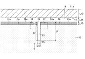
図8は、図1に示した窓ガラス100の一部を拡大した平面図であって、窓ガラス100が車両に搭載された状態を示したものである。窓ガラス100は、第1のガラス板11のガラス縁11aが重なるように車体開口端41に取り付けられる。車体開口端41は、窓ガラス100が取り付けられる車体部位であり、例えば、車体に形成された窓枠のフランジ部である。
FIG. 8 is an enlarged plan view of a part of the
アンテナ1のアンテナ利得を効果的に増大させるには、スロット23が、窓ガラス100が車体開口端41に取り付けられたときに車体開口端41に沿う方向に対して直交するように設けられるとよい。
In order to effectively increase the antenna gain of the antenna 1, the
アンテナ1は、車両のルーフ側の車体開口端41の近傍に配置されることが、アンテナ利得向上の点で好ましいが、車両のルーフ側とは異なる車体開口端(例えば、ピラー側の車体開口端、シャシー側の車体開口端など)の近傍に配置されてもよい。
The antenna 1 is preferably disposed in the vicinity of the vehicle
図8の場合、スロット23は、バスバー26に形成されたバスバースロット部31と導電膜13に形成された導電膜スロット部32とで構成され、導電膜13の面内方向に直線的に延在し、互いに連通するスロット部である。
In the case of FIG. 8, the
アンテナ1が受信する電波の所定の周波数帯の中心周波数における空気中の波長をλ0とし、スロット23が設けられた面におけるガラス波長短縮率をkとし、λg=k・λ0とする。なお、ガラス波長短縮率kは、例えば一枚のガラス板に導電膜が形成されている場合は約0.64であり、二枚のガラス板が中間膜を介して積層された合わせガラスであり、導電膜が中間膜に接する面に形成されている場合は約0.5である。この場合、スロット23の開放端24からのスロット長L11が、(1/10)・λg以上(1/2)・λg以下であることが好ましく、(1/8)・λg以上(1/4)・λg以下であることが更に好ましい。図8の場合、スロット23の開放端24からのスロット長L11は、開放端24から先端部25までの最短経路の距離であり、スロット23の長手方向における長さに相当する。これにより、アンテナ利得を効果的に上げることができる。The wavelength in the air at the center frequency of a predetermined frequency band of the radio wave received by the antenna 1 is λ 0 , the glass wavelength shortening rate on the surface where the
例えば、アンテナ1が受信すべき周波数帯が地上デジタルテレビ放送帯470〜710MHzの場合、スロット23の開放端24からのスロット長L11が、25mm以上130mm以下であることが好ましく、30mm以上65mm以下であることが更に好ましい。これにより、アンテナ利得を効果的に上げることができる。
For example, when the frequency band to be received by the antenna 1 is the terrestrial digital
また、スロット23のスロット幅L12は、0.01mm以上30mm以下であることが好ましい。これにより、地上デジタルテレビ放送帯470〜710MHzにおけるアンテナ利得を効果的に上げることができる。図3の場合、スロット幅L12は、スロット23の長手方向と直交する方向におけるスロット23の幅である。
The slot width L12 of the
例えば、電極17を信号線側の電極とし、電極16をアース線側の電極とした場合、電極17は、車体側に搭載された信号処理装置(例えば、アンプなど)に結線された信号線に導通可能に接続され、電極16は、車体側のグランド部位に結線された接地線に導通可能に接続される。車体側のグランド部位として、例えば、ボディーアース、電極17に接続される信号線が結線される信号処理装置のグランドなどが挙げられる。なお、電極17をアース線側の電極とし、電極16を信号線側の電極としてもよい。
For example, when the
アンテナ1に構成されるスロット23に沿って励起した電流による電波の受信信号は、一対の電極16,17に通電可能に接続された導電性部材を介して、車両に搭載された信号処理装置に伝達される。この導電性部材として、AV線や同軸ケーブルなどの給電線が用いられるとよい。
A radio wave reception signal generated by a current excited along the
アンテナ1に一対の電極16,17を介して給電するための給電線として、同軸ケーブルを用いる場合には、例えば、同軸ケーブルの内部導体を電極17に電気的に接続し、同軸ケーブルの外部導体を電極16に接続すればよい。また、信号処理装置に接続されている導線等の導電性部材と一対の電極16,17とを電気的に接続するためのコネクタを、電極16,17に実装する構成を採用してもよい。このようなコネクタによって、同軸ケーブルの内部導体を電極17に取り付けることが容易になるとともに、同軸ケーブルの外部導体を電極16に取り付けることが容易になる。さらに、一対の電極16,17に突起状の導電性部材を設置し、窓ガラス100が取り付けられる車体のフランジ部に設けられた給電部にその突起状の導電性部材が接触、嵌合するような構成としてもよい。
When a coaxial cable is used as a feed line for feeding power to the antenna 1 via the pair of
一対の電極16,17の形状、及び各電極の間隔は、上記の導電性部材又はコネクタの実装面の形状や、それらの実装面の間隔を考慮して決めるとよい。例えば、正方形、略正方形、長方形、略長方形などの方形状や多角形状が実装上好ましい。なお、円、略円、楕円、略楕円などの円状でもよい。
The shape of the pair of
また、一対の電極16,17は、例えば、銀ペースト等の、導電性金属を含有するペーストを、ガラス板12の車内側表面にプリントし、焼付けて形成される。しかし、この形成方法に限定されず、銅等の導電性物質からなる、線状体又は箔状体を、ガラス板12の車内側表面に形成してもよく、ガラス板12に接着剤等により貼付してもよい。
The pair of
また、一対の電極16,17を車外側から見えなくするために、電極16,17とガラス板11との間に、ガラス板11の面に形成される隠蔽膜を設けてもよい。隠蔽膜は黒色セラミックス膜等の焼成体であるセラミックスが挙げられる。この場合、窓ガラスの車外側から見ると、隠蔽膜により隠蔽膜上に設けられている一対の電極16,17及びアンテナ1の一部が車外から見えなくなり、デザインの優れた窓ガラスとなる。
Further, a concealing film formed on the surface of the
図9〜14は、アンテナ1とは形態の異なる他のアンテナのバリエーションを示したものである。これらの形態でも、アンテナ利得を増大できる。 9 to 14 show variations of other antennas different in form from the antenna 1. These forms can also increase the antenna gain.
図9のアンテナ2の場合、バスバー26は、幅広領域29と、幅広領域29よりも幅が狭い領域(幅狭領域28)とを有している。スロット23のバスバー26に形成されたバスバースロット部31は、幅広領域29に形成される。スロット23を幅広領域29に少なくとも形成することによって、スロット23の周りで接する低抵抗部分が図8の場合に比べて広がるため、スロット23に沿って電流が励起しやすく、アンテナ2のアンテナ利得が向上する。
In the case of the
図10のアンテナ3の場合、スロット23は、導電膜13に形成されずに、バスバー26の幅広領域29のみに形成された溝部である。スロット23は、全体がバスバー26内のみに形成されている。これにより、スロット23の周りで接する低抵抗部分が更に広がるため、スロット23に沿って電流が励起しやすく、アンテナ3のアンテナ利得が向上する。また、バスバー26がスロット23で分割されないため、バスバー26の電源部への接続が一か所に集約できる。
In the case of the antenna 3 of FIG. 10, the
図11のアンテナ4は、スロット23の近傍にスロット23とは接続しない独立スロット61,62,63を備えている。独立スロット61,62はバスバー26のみに形成されており、独立スロット63は、導電膜13のみに形成されている。独立スロット61,62は、スロット23に接続されずに別に設けられており、電熱膜50の外縁においても開放されないように、バスバー26を線状に除去した部位である。図11の場合、独立スロット61,62は、スロット23の長手方向に対して直交するように配置されているが、スロット23の長手方向に平行になるように配置されてもよい。独立スロット63は、スロット23に接続されずに別に設けられており、電熱膜50の外縁においても開放されないように、導電膜13を線状に除去した部位である。図11の場合、独立スロット63は、スロット23の長手方向に平行になるように配置されているが、スロット23の長手方向に対して直交するように配置されてもよい。このような独立スロットにより、スロット23の広帯域化が可能になる。
The
図12のアンテナ5の場合、スロット73は、全体がバスバー26内のみに形成されている。また、スロット73は電熱膜50の外縁から離れる方向に延伸する主スロット部77と電熱膜50の外縁と平行な平行スロット部78とでL字状に形成されている。スロット73の一端が、バスバー26のバスバー縁26aで開放する開放端74であり、スロット73のもう一方の一端が、いずれの端部でも開放されずにバスバー26内で閉じた先端部75である。スロット73がL字状のスロットを有することによって、導電膜13の面内方向へのスロット長を短くできるため、アンテナ5の背丈を低くすることが可能であり、窓ガラスの見栄えが向上する。また、バスバー26がスロット73で分割されないため、バスバー26の電源部への接続が一か所に集約できる。
In the case of the antenna 5 of FIG. 12, the
また、図12には、導電膜13の膜縁13aが、バスバー26の領域のうちスロット73が形成された領域のバスバー縁26aに対して、ガラス縁11aとは反対側に後退した形態例が示されている。幅L32,L35,L36が、バスバー26と導電膜13が重なっている部分の幅に相当する。
FIG. 12 shows an example in which the
図13のアンテナ6は、スロット形状は図12の場合と同じであるが、バスバー26の領域のうちスロット73が形成された領域のバスバー縁26aが、導電膜13の膜縁13aに対してガラス縁11a寄りに凸状に形成されている形態を有している。幅L37が、バスバー26と導電膜13が重なっている部分の幅に相当する。
The
図14のアンテナ7の場合、スロット73は、図12の場合に対して、さらに、平行スロット部78と接続する副スロット部79を備えている。副スロット部79は、電熱膜50の外縁で開放する端部である開放端76を有している。スロット73は、主スロット部77と平行スロット部78と副スロット部79とでF字状に形成されている。スロット73の一端が、バスバー26のバスバー縁26aで開放する開放端74であり、スロット73のもう一方の一端が、いずれの端部でも開放されずにバスバー26内で閉じた先端部75である。スロット73は、開放端74から先端部75までのスロット経路上に、スロット73の形状がF字状になるように、バスバー縁26aで開放する副スロット部79を有している。スロット73がF字状のスロットを有することによって、導電膜13の面内方向へのスロット長を短くできるため、アンテナ7の背丈を低くすることが可能であり、窓ガラスの見栄えが向上する。また、バスバー26がスロット73で分割されないため、バスバー26の電源部への接続が一か所に集約できる。
In the case of the antenna 7 of FIG. 14, the
なお、L字状スロットやF字状スロットに限らず、例えばメアンダ状スロットでも、窓ガラスの見栄えの向上が可能である。 The appearance of the window glass can be improved not only in the L-shaped slot and the F-shaped slot but also in a meander-shaped slot, for example.
以上、車両用窓ガラス及びアンテナを実施形態例により説明したが、本発明は上記の実施形態例に限定されるものではない。他の実施形態例の一部又は全部との組み合わせや置換などの種々の変形及び改良が、本発明の範囲内で可能である。 As mentioned above, although the vehicle window glass and the antenna were demonstrated by the embodiment, this invention is not limited to said embodiment. Various modifications and improvements, such as combinations and substitutions with part or all of other example embodiments, are possible within the scope of the present invention.
例えば図1において、導電膜13は、バスバー26,27間に取り付けられたセンサが、バスバー26,27間の電圧、電流又は抵抗などの変化をモニターすることによって、窓ガラス100の割れを検出することを可能にする導体でもよく、その用途は限定されない。
For example, in FIG. 1, the
また、バスバー26は、窓ガラス100が車両に搭載されたときに車幅方向の一方の側となる膜縁13bに沿って配置されてもよいし、バスバー27は、窓ガラス100が車両に搭載されたときに車幅方向の他方の側となる膜縁13dに沿って配置されてもよい。
Further, the
また、スロット23の先端部25がバスバー26に形成され、スロット23の開放端24側の根元部が導電膜13に形成されてもよい。また、スロット23の先端部25及び開放端24側の根元部が導電膜13に形成され、先端部25と根元部との間におけるスロット23の中間部がバスバー26に形成されてもよい。
Alternatively, the
実際の自動車用窓ガラスに取り付けられたアンテナの形態別のアンテナ利得の実測結果について示す。なお、アンテナ利得の測定時の積層構成は、実験の便宜上、図7に示した形態において、導電膜13が形成された樹脂フィルム15をガラス板11の外側表面に形成された構成である。
The actual measurement result of the antenna gain according to the form of the antenna attached to the actual window glass for automobiles is shown. In addition, the lamination | stacking structure at the time of measurement of antenna gain is the structure which formed the
アンテナ利得は、アンテナが形成された自動車用窓ガラスを、ターンテーブル上の自動車の窓枠に水平面に対してスロット部分が約25°傾けた状態で組みつけて実測された。電極17に同軸ケーブルの内部導体が接続されるように、また電極16に同軸ケーブルの外部導体が接続されるようにコネクタが取り付けられていて、電極16,17は同軸ケーブルを介してネットワークアナライザに接続された。水平方向から窓ガラスに対して全方向から電波が照射されるように、ターンテーブルを回転させた。
The antenna gain was measured by assembling the automobile window glass on which the antenna was formed, with the slot portion inclined about 25 ° with respect to the horizontal plane on the window frame of the automobile on the turntable. A connector is attached so that the inner conductor of the coaxial cable is connected to the
アンテナ利得の測定は、ターンテーブルの中心に、アンテナが形成された自動車用窓ガラスを組みつけた自動車の車両中心をセットして、自動車を360°回転させて行った。アンテナ利得のデータは、回転角度1°毎に、地上デジタルテレビ放送帯470〜710MHzの周波数範囲において6MHz毎に測定された。電波の発信位置とアンテナ導体との仰角は略水平方向(地面と平行な面を仰角=0°、天頂方向を仰角=90°とする場合、仰角=0°の方向)で測定した。
The antenna gain was measured by setting the vehicle center of an automobile in which an automobile window glass having an antenna was assembled at the center of the turntable and rotating the automobile 360 °. The antenna gain data was measured every 6 MHz in the frequency range of the terrestrial digital
<例1>
図15は、上掲の特許文献1のアンテナ101が形成された自動車用窓ガラスが車両に搭載された状態での平面図を示したものである。図15の形態の測定時、図1と同一寸法の窓ガラスを使用し、図15のスロット23の位置が図1のスロット23の位置に一致するように配置した。図15のアンテナ101は、図8の形態に対してバスバー26が設けられていない形態を有するものである。<Example 1>
FIG. 15 is a plan view showing a state in which the window glass for an automobile on which the
図16は、水平偏波の電波を照射したときの、アンテナ1,2,101の形態別のアンテナ利得の実測データから、アンテナ101のアンテナ利得が0dBとなるようにアンテナ1,2それぞれのアンテナ利得についてアンテナ101との差を示したグラフである。「アンテナ101」は、図15の形態を表す。「アンテナ1」は、図8の形態を表す。「アンテナ2」は、図9の形態を表す。
FIG. 16 shows the
図16に示した470〜710MHzの周波数範囲において6MHz毎に測定されたアンテナ利得差について、その平均値は、単位をdBとすると、
アンテナ1:0.64(水平偏波)
アンテナ2:0.82(水平偏波)
と、算出された。これによれば、バスバー26を設けることによって、アンテナ利得が0.64dB上昇し、幅広領域29を設けることによって、さらに0.18dB上昇し、アンテナ利得が向上していることがわかる。With respect to the antenna gain difference measured every 6 MHz in the frequency range of 470 to 710 MHz shown in FIG.
Antenna 1: 0.64 (horizontal polarization)
Antenna 2: 0.82 (horizontal polarization)
And calculated. According to this, it can be seen that providing the
なお、図16において、アンテナ利得の測定時の図8,9,15の各部の寸法は、単位をmmとすると、
L11:52
L12:10
L13:21
L14:10
L15:8
L16(スロット23を挟んだ一対の幅広領域29ともに):20
L17(スロット23を挟んだ一対の幅広領域29ともに):20
L51:1166
L52:1104
L53:1400
L54:1400
L55:1285
L56:1402
L57:802
L58:693
L59:650
L60:757
とした。なお、電極16,17の形状は、一辺が20mmの正方形とし、電極16,17間の距離は、10mmとし、導電膜13のシート抵抗は、1.0Ωとした。In FIG. 16, when measuring the antenna gain, the dimensions of the respective parts in FIGS.
L11: 52
L12: 10
L13: 21
L14: 10
L15: 8
L16 (both a pair of
L17 (both a pair of
L51: 1166
L52: 1104
L53: 1400
L54: 1400
L55: 1285
L56: 1402
L57: 802
L58: 693
L59: 650
L60: 757
It was. In addition, the shape of the
<例2>
図17は、アンテナ102が形成された自動車用窓ガラスが車両に搭載された状態での平面図を示したものである。図17の形態の測定時、図1と同一寸法の窓ガラスを使用し、図17の開放端74の位置が図1の開放端24の位置に一致するように配置した。図17のアンテナ102は、図12の形態に対してバスバー26が設けられていない形態を有するものである。<Example 2>
FIG. 17 is a plan view showing a state in which the window glass for an automobile on which the
図18は、水平偏波の電波を照射したときの、アンテナ5,101,102の形態別のアンテナ利得の実測データから、アンテナ101のアンテナ利得が0dBとなるようにアンテナ5,102それぞれのアンテナ利得についてアンテナ101との差を示したグラフである。「アンテナ101」は、図15の形態を表す。「アンテナ5」は、図12の形態を表す。「アンテナ102」は、図17の形態を表す。
FIG. 18 shows the antennas of the
図18に示した470〜710MHzの周波数範囲において6MHz毎に測定されたアンテナ利得について、その平均値は、単位をdBとすると、
アンテナ5:0.09(水平偏波)
アンテナ102:−2.32(水平偏波)
と、算出された。これによれば、図15のアンテナ101を図17のアンテナ102のように背丈を低くすることによって、アンテナ利得が低下したとしても、図12のアンテナ5のようにバスバー26を設けることによって、その低下分を相殺できることがわかる。As for the antenna gain measured every 6 MHz in the frequency range of 470 to 710 MHz shown in FIG.
Antenna 5: 0.09 (horizontal polarization)
Antenna 102: -2.32 (horizontal polarization)
And calculated. According to this, even if the antenna gain is reduced by lowering the height of the
なお、図18において、アンテナ利得の測定時の図12,15,17の各部の寸法は、単位をmmとすると、
L21:10
L22:50
L23:18
L24:3
L31:8
L32:5
L33:30
L34:300
L35:10
L36:10
とした。なお、図1と共通する箇所については、上記の<例1>の場合と同一である。また、電極16,17間の距離は、10mmとし、導電膜13のシート抵抗は、1.0Ωとした。また、電極16,17の形状は、図7,12の場合、一辺が14mmの正方形とし、図10の場合、一辺が20mmの正方形とした。In FIG. 18, the dimensions of each part of FIGS. 12, 15, and 17 when measuring the antenna gain are expressed in units of mm.
L21: 10
L22: 50
L23: 18
L24: 3
L31: 8
L32: 5
L33: 30
L34: 300
L35: 10
L36: 10
It was. The parts common to those in FIG. 1 are the same as those in the above <Example 1>. The distance between the
本発明は、例えば、地上波デジタルテレビ放送、UHF帯のアナログテレビ放送及び米国のデジタルテレビ放送、欧州連合地域のデジタルテレビ放送又は中華人民共和国のデジタルテレビ放送を受信する自動車用のアンテナとして利用されると好適である。その他、日本のFM放送帯(76〜90MHz)、米国のFM放送帯(88〜108MHz)、テレビVHF帯(90〜108MHz、170〜222MHz)、車両用キーレスエントリーシステム(300〜450MHz)にも利用できる。 INDUSTRIAL APPLICABILITY The present invention is used as an antenna for an automobile that receives, for example, terrestrial digital TV broadcast, UHF analog TV broadcast, US digital TV broadcast, European Union digital TV broadcast or People's Republic of China digital TV broadcast. It is preferable. Also used for FM broadcast band in Japan (76-90MHz), FM broadcast band in the US (88-108MHz), TV VHF band (90-108MHz, 170-222MHz), keyless entry system for vehicles (300-450MHz) it can.
また、自動車電話用の800MHz帯(810〜960MHz)、自動車電話用の1.5GHz帯(1.429〜1.501GHz)、GPS(Global Positioning System)、人工衛星のGPS信号1575.42MHz)、VICS(登録商標)(Vehicle Information and Communication System:2.5GHz)にも利用できる。 Also, 800 MHz band (810 to 960 MHz) for automobile telephones, 1.5 GHz band (1.429 to 1.501 GHz) for automobile telephones, GPS (Global Positioning System), GPS signals of artificial satellites 1575.42 MHz), VICS (Registered trademark) (Vehicle Information and Communication System: 2.5 GHz).
さらに、ETC通信(Electronic Toll Collection System:ノンストップ自動料金収受システム、路側無線装置の送信周波数:5.795GHz又は5.805GHz、路側無線装置の受信周波数:5.835GHz又は5.845GHz)、専用狭域通信(DSRC:Dedicated Short Range Communication、915MHz帯、5.8GHz帯、60GHz帯)、マイクロ波(1GHz〜30GHz)、ミリ波(30〜300GHz)、及び、SDARS(Satellite Digital Audio Radio Service (2.34GHz、2.6GHz))の通信に利用してもよい。 Furthermore, ETC communication (Electronic Toll Collection System: non-stop automatic toll collection system, roadside wireless device transmission frequency: 5.795 GHz or 5.805 GHz, roadside wireless device reception frequency: 5.835 GHz or 5.845 GHz), dedicated narrow Area communication (DSRC: Dedicated Short Range Communication, 915 MHz band, 5.8 GHz band, 60 GHz band), microwave (1 GHz to 30 GHz), millimeter wave (30 to 300 GHz), and SDARS (Satellite Digital Audio Radio Service (2. 34 GHz, 2.6 GHz)).
本国際出願は、2013年3月27日に出願した日本国特許出願第2013−67197号に基づく優先権を主張するものであり、日本国特許出願第2013−67197号の全内容を本国際出願に援用する。 This international application claims priority based on Japanese Patent Application No. 2013-67197 filed on Mar. 27, 2013. The entire contents of Japanese Patent Application No. 2013-67197 are hereby incorporated by reference. Incorporated into.
1〜7,101,102 アンテナ
11,12 ガラス板
11a〜11d,12a〜12d ガラス縁
13 導電膜
13a,13b,13c,13d 膜縁
14A,14B 中間膜
15 樹脂フィルム
16,17 電極
21,22 投影領域
23,73 スロット
24,74,76 開放端
25,75 先端部
26,27 バスバー
26a,27a バスバー縁
28 幅狭領域
29 幅広領域
31 バスバースロット部
32 導電膜スロット部
33 誘電体基板
41 車体開口端
42 電源部
43 グランド部
50 電熱膜
61,62,63 独立スロット
77 主スロット部
78 平行スロット部
79 副スロット部
100 窓ガラス1 to 7, 101, 102
Claims (14)
前記電熱膜は、導電膜と、前記導電膜よりも低抵抗の帯状電極とを備え、
前記帯状電極は、前記導電膜の外縁の少なくとも対向する二辺に沿って配置され且つ前記導電膜と直流的に接続され、
前記導電膜が前記帯状電極を介して通電可能に構成される車両用窓ガラスであって、
前記誘電体を挟んで前記電熱膜に対向して配置された一対の電極と、前記一対の電極に平面視で挟まれるように少なくとも一部が前記帯状電極に形成されたスロットとを有するアンテナを備え、
前記スロットの一端が、前記電熱膜の外縁で開放する開放端であることを特徴とする車両用窓ガラス。A glass plate, a dielectric, and an electrothermal film provided between the glass plate and the dielectric,
The electrothermal film includes a conductive film and a strip electrode having a lower resistance than the conductive film,
The strip electrode is disposed along at least two opposite sides of the outer edge of the conductive film and is connected to the conductive film in a direct current manner.
The vehicle window glass is configured such that the conductive film can be energized through the strip electrode,
An antenna having a pair of electrodes disposed opposite to the electrothermal film with the dielectric interposed therebetween, and a slot at least partially formed in the strip electrode so as to be sandwiched between the pair of electrodes in plan view Prepared,
One end of the slot is an open end that opens at the outer edge of the electrothermal membrane.
前記スロットの前記開放端からのスロット長が、(1/10)・λg以上(1/2)・λg以下である、請求項1から5のいずれか一項に記載の車両用窓ガラス。When the wavelength in the air at the center frequency of a predetermined frequency band of the radio wave received by the antenna is λ 0 , the glass wavelength shortening rate on the surface where the slot is provided is k, and λ g = k · λ 0
6. The vehicle window glass according to claim 1, wherein a slot length from the open end of the slot is not less than (1/10) · λ g and not more than (½) · λ g. .
前記スロットは、前記幅広領域に形成された、請求項1から9のいずれか一項に記載の車両用窓ガラス。The strip electrode has a wide region and a narrow region,
The vehicle window glass according to any one of claims 1 to 9, wherein the slot is formed in the wide region.
前記スロットの一端が、前記電熱膜の外縁で開放する開放端であることを特徴とするアンテナ。An electric heating film provided with a dielectric, a conductive film and at least two opposite sides of the outer edge of the conductive film, and having a strip-like electrode having a lower resistance than the conductive film, and opposed to the electric heating film with the dielectric interposed therebetween A pair of electrodes disposed in a slot, and at least a part of the slot-shaped electrode formed so as to be sandwiched between the pair of electrodes in a plan view,
One end of the slot is an open end that opens at an outer edge of the electrothermal film.
Applications Claiming Priority (3)
| Application Number | Priority Date | Filing Date | Title |
|---|---|---|---|
| JP2013067197 | 2013-03-27 | ||
| JP2013067197 | 2013-03-27 | ||
| PCT/JP2014/058902 WO2014157535A1 (en) | 2013-03-27 | 2014-03-27 | Vehicular window glass, and antenna |
Publications (2)
| Publication Number | Publication Date |
|---|---|
| JPWO2014157535A1 JPWO2014157535A1 (en) | 2017-02-16 |
| JP6172265B2 true JP6172265B2 (en) | 2017-08-02 |
Family
ID=51624496
Family Applications (1)
| Application Number | Title | Priority Date | Filing Date |
|---|---|---|---|
| JP2015508701A Active JP6172265B2 (en) | 2013-03-27 | 2014-03-27 | Vehicle window glass and antenna |
Country Status (5)
| Country | Link |
|---|---|
| US (1) | US9755300B2 (en) |
| EP (1) | EP2980919B1 (en) |
| JP (1) | JP6172265B2 (en) |
| CN (1) | CN105075009B (en) |
| WO (1) | WO2014157535A1 (en) |
Families Citing this family (25)
| Publication number | Priority date | Publication date | Assignee | Title |
|---|---|---|---|---|
| US9337525B2 (en) * | 2014-02-03 | 2016-05-10 | Pittsburgh Glass Works, Llc | Hidden window antenna |
| CN107615584B (en) | 2015-05-21 | 2020-07-24 | Agc株式会社 | Window glass for vehicle and antenna |
| GB201509630D0 (en) * | 2015-06-03 | 2015-07-15 | Pilkington Group Ltd | Laminated glazing |
| DE102015016281A1 (en) * | 2015-12-16 | 2017-06-22 | GM Global Technology Operations LLC (n. d. Ges. d. Staates Delaware) | Windshield of a motor vehicle, system with windshield and motor vehicle |
| JP6743486B2 (en) * | 2016-05-24 | 2020-08-19 | Agc株式会社 | Vehicle window glass |
| JP2017212553A (en) * | 2016-05-24 | 2017-11-30 | 旭硝子株式会社 | Window glass for vehicle |
| WO2018079415A1 (en) * | 2016-10-25 | 2018-05-03 | 日本板硝子株式会社 | Window glass |
| EP3605726B1 (en) * | 2017-03-29 | 2023-05-24 | Central Glass Company, Limited | Antenna and window glass |
| DE102017210989B3 (en) * | 2017-06-28 | 2018-05-17 | Audi Ag | Laminated glass for a vehicle |
| US10673122B2 (en) * | 2017-10-20 | 2020-06-02 | Gentex Corporation | Vehicle communication module with improved transmission |
| DE112018004604B4 (en) * | 2017-10-20 | 2023-12-21 | AGC Inc. | Laminated glass for a vehicle |
| US11611857B2 (en) * | 2017-11-06 | 2023-03-21 | Sumitomo Electric Industries, Ltd. | Vehicle-mounted transmission system |
| US10608330B2 (en) * | 2017-11-14 | 2020-03-31 | Gm Global Technology Operations, Llc | Method and apparatus to conceal near transparent conductors |
| CO2018000469A1 (en) * | 2017-11-30 | 2018-04-30 | Agp America Sa | Automotive laminate with invisible solid edge substrate compensation layer |
| US10721795B2 (en) | 2018-02-20 | 2020-07-21 | Agc Automotive Americas R&D, Inc. | Window assembly comprising conductive transparent layer and conductive element implementing hybrid bus-bar/antenna |
| US10923795B2 (en) * | 2018-04-12 | 2021-02-16 | Pittsburgh Glass Works, Llc | Hidden multi-band window antenna |
| DE102019118769A1 (en) * | 2018-07-23 | 2020-03-05 | AGC Inc. | Window pane for a vehicle and window pane device for a vehicle |
| JP7355027B2 (en) * | 2018-10-05 | 2023-10-03 | Agc株式会社 | antenna system |
| JP7205341B2 (en) * | 2019-03-26 | 2023-01-17 | Agc株式会社 | vehicle glass |
| JP2023553813A (en) * | 2019-11-22 | 2023-12-26 | ピッツバーグ グラス ワークス、エルエルシー | Heatable vehicle window glass with antenna |
| JPWO2022004559A1 (en) * | 2020-06-29 | 2022-01-06 | ||
| US11955713B2 (en) | 2020-06-30 | 2024-04-09 | Novatel Inc. | Antenna with tilted beam for use on angled surfaces |
| JP2022087391A (en) * | 2020-12-01 | 2022-06-13 | Agc株式会社 | Glass structure and manufacturing method therefor |
| JP7444052B2 (en) | 2020-12-25 | 2024-03-06 | Agc株式会社 | Glass structure and its manufacturing method |
| US11735823B2 (en) * | 2022-01-13 | 2023-08-22 | GM Global Technology Operations LLC | Coplanar antenna structure having a wide slot |
Family Cites Families (10)
| Publication number | Priority date | Publication date | Assignee | Title |
|---|---|---|---|---|
| DE3808401A1 (en) * | 1988-03-12 | 1989-09-21 | Blaupunkt Werke Gmbh | VEHICLE WINDOW WASHER |
| JP2001185928A (en) * | 1999-12-22 | 2001-07-06 | Asahi Glass Co Ltd | Glass antenna for vehicle |
| JP5023956B2 (en) * | 2007-10-15 | 2012-09-12 | 旭硝子株式会社 | Glass antenna for automobile |
| JP2009155169A (en) * | 2007-12-27 | 2009-07-16 | Asahi Glass Co Ltd | Heat-ray reflecting glass and method for manufacturing heat-ray reflecting glass |
| BRPI1015942A2 (en) * | 2009-07-09 | 2016-04-19 | Asahi Glass Co Ltd | vehicle window glass and antenna. |
| GB0922191D0 (en) * | 2009-12-21 | 2010-02-03 | Pilkington Group Ltd | Vehicle glazing |
| JP5575596B2 (en) * | 2010-09-22 | 2014-08-20 | 日本写真印刷株式会社 | Multi-touch panel with equipotential distortion correction |
| US8576130B2 (en) * | 2010-10-22 | 2013-11-05 | Pittsburgh Glass Works, Llc | Wideband antenna |
| JP2014033243A (en) * | 2010-11-30 | 2014-02-20 | Asahi Glass Co Ltd | Vehicle window glass and antenna |
| US9337525B2 (en) * | 2014-02-03 | 2016-05-10 | Pittsburgh Glass Works, Llc | Hidden window antenna |
-
2014
- 2014-03-27 EP EP14774220.9A patent/EP2980919B1/en active Active
- 2014-03-27 WO PCT/JP2014/058902 patent/WO2014157535A1/en active Application Filing
- 2014-03-27 JP JP2015508701A patent/JP6172265B2/en active Active
- 2014-03-27 CN CN201480018551.9A patent/CN105075009B/en active Active
-
2015
- 2015-09-14 US US14/853,227 patent/US9755300B2/en active Active
Also Published As
| Publication number | Publication date |
|---|---|
| JPWO2014157535A1 (en) | 2017-02-16 |
| EP2980919B1 (en) | 2017-11-29 |
| EP2980919A4 (en) | 2016-12-21 |
| CN105075009A (en) | 2015-11-18 |
| US9755300B2 (en) | 2017-09-05 |
| WO2014157535A1 (en) | 2014-10-02 |
| CN105075009B (en) | 2017-08-22 |
| US20160006112A1 (en) | 2016-01-07 |
| EP2980919A1 (en) | 2016-02-03 |
Similar Documents
| Publication | Publication Date | Title |
|---|---|---|
| JP6172265B2 (en) | Vehicle window glass and antenna | |
| JP6696502B2 (en) | Vehicle window glass and antenna | |
| US9118114B2 (en) | Window glass for vehicle and antenna | |
| US9509038B2 (en) | Vehicle window glass and antenna | |
| WO2012090883A1 (en) | Antenna | |
| JP5655782B2 (en) | Vehicle window glass and antenna | |
| WO2014142312A1 (en) | Window glass for vehicle | |
| CN107453029B (en) | Window glass for vehicle | |
| US20170346154A1 (en) | Window glass for vehicle |
Legal Events
| Date | Code | Title | Description |
|---|---|---|---|
| TRDD | Decision of grant or rejection written | ||
| A01 | Written decision to grant a patent or to grant a registration (utility model) |
Free format text: JAPANESE INTERMEDIATE CODE: A01 Effective date: 20170606 |
|
| A61 | First payment of annual fees (during grant procedure) |
Free format text: JAPANESE INTERMEDIATE CODE: A61 Effective date: 20170619 |
|
| R150 | Certificate of patent or registration of utility model |
Ref document number: 6172265 Country of ref document: JP Free format text: JAPANESE INTERMEDIATE CODE: R150 |
|
| S533 | Written request for registration of change of name |
Free format text: JAPANESE INTERMEDIATE CODE: R313533 |
|
| R350 | Written notification of registration of transfer |
Free format text: JAPANESE INTERMEDIATE CODE: R350 |
|
| R250 | Receipt of annual fees |
Free format text: JAPANESE INTERMEDIATE CODE: R250 |
|
| R250 | Receipt of annual fees |
Free format text: JAPANESE INTERMEDIATE CODE: R250 |
|
| R250 | Receipt of annual fees |
Free format text: JAPANESE INTERMEDIATE CODE: R250 |
|
| R250 | Receipt of annual fees |
Free format text: JAPANESE INTERMEDIATE CODE: R250 |