JP2009155169A - Heat-ray reflecting glass and method for manufacturing heat-ray reflecting glass - Google Patents
Heat-ray reflecting glass and method for manufacturing heat-ray reflecting glass Download PDFInfo
- Publication number
- JP2009155169A JP2009155169A JP2007336133A JP2007336133A JP2009155169A JP 2009155169 A JP2009155169 A JP 2009155169A JP 2007336133 A JP2007336133 A JP 2007336133A JP 2007336133 A JP2007336133 A JP 2007336133A JP 2009155169 A JP2009155169 A JP 2009155169A
- Authority
- JP
- Japan
- Prior art keywords
- film
- oxygen
- heat ray
- chromium
- ray reflective
- Prior art date
- Legal status (The legal status is an assumption and is not a legal conclusion. Google has not performed a legal analysis and makes no representation as to the accuracy of the status listed.)
- Withdrawn
Links
Images


Classifications
-
- C—CHEMISTRY; METALLURGY
- C03—GLASS; MINERAL OR SLAG WOOL
- C03C—CHEMICAL COMPOSITION OF GLASSES, GLAZES OR VITREOUS ENAMELS; SURFACE TREATMENT OF GLASS; SURFACE TREATMENT OF FIBRES OR FILAMENTS MADE FROM GLASS, MINERALS OR SLAGS; JOINING GLASS TO GLASS OR OTHER MATERIALS
- C03C17/00—Surface treatment of glass, not in the form of fibres or filaments, by coating
- C03C17/34—Surface treatment of glass, not in the form of fibres or filaments, by coating with at least two coatings having different compositions
- C03C17/3411—Surface treatment of glass, not in the form of fibres or filaments, by coating with at least two coatings having different compositions with at least two coatings of inorganic materials
- C03C17/3429—Surface treatment of glass, not in the form of fibres or filaments, by coating with at least two coatings having different compositions with at least two coatings of inorganic materials at least one of the coatings being a non-oxide coating
- C03C17/3435—Surface treatment of glass, not in the form of fibres or filaments, by coating with at least two coatings having different compositions with at least two coatings of inorganic materials at least one of the coatings being a non-oxide coating comprising a nitride, oxynitride, boronitride or carbonitride
-
- C—CHEMISTRY; METALLURGY
- C03—GLASS; MINERAL OR SLAG WOOL
- C03C—CHEMICAL COMPOSITION OF GLASSES, GLAZES OR VITREOUS ENAMELS; SURFACE TREATMENT OF GLASS; SURFACE TREATMENT OF FIBRES OR FILAMENTS MADE FROM GLASS, MINERALS OR SLAGS; JOINING GLASS TO GLASS OR OTHER MATERIALS
- C03C17/00—Surface treatment of glass, not in the form of fibres or filaments, by coating
- C03C17/34—Surface treatment of glass, not in the form of fibres or filaments, by coating with at least two coatings having different compositions
- C03C17/36—Surface treatment of glass, not in the form of fibres or filaments, by coating with at least two coatings having different compositions at least one coating being a metal
- C03C17/3602—Surface treatment of glass, not in the form of fibres or filaments, by coating with at least two coatings having different compositions at least one coating being a metal the metal being present as a layer
- C03C17/3657—Surface treatment of glass, not in the form of fibres or filaments, by coating with at least two coatings having different compositions at least one coating being a metal the metal being present as a layer the multilayer coating having optical properties
- C03C17/366—Low-emissivity or solar control coatings
-
- C—CHEMISTRY; METALLURGY
- C23—COATING METALLIC MATERIAL; COATING MATERIAL WITH METALLIC MATERIAL; CHEMICAL SURFACE TREATMENT; DIFFUSION TREATMENT OF METALLIC MATERIAL; COATING BY VACUUM EVAPORATION, BY SPUTTERING, BY ION IMPLANTATION OR BY CHEMICAL VAPOUR DEPOSITION, IN GENERAL; INHIBITING CORROSION OF METALLIC MATERIAL OR INCRUSTATION IN GENERAL
- C23C—COATING METALLIC MATERIAL; COATING MATERIAL WITH METALLIC MATERIAL; SURFACE TREATMENT OF METALLIC MATERIAL BY DIFFUSION INTO THE SURFACE, BY CHEMICAL CONVERSION OR SUBSTITUTION; COATING BY VACUUM EVAPORATION, BY SPUTTERING, BY ION IMPLANTATION OR BY CHEMICAL VAPOUR DEPOSITION, IN GENERAL
- C23C14/00—Coating by vacuum evaporation, by sputtering or by ion implantation of the coating forming material
- C23C14/0021—Reactive sputtering or evaporation
- C23C14/0036—Reactive sputtering
-
- C—CHEMISTRY; METALLURGY
- C23—COATING METALLIC MATERIAL; COATING MATERIAL WITH METALLIC MATERIAL; CHEMICAL SURFACE TREATMENT; DIFFUSION TREATMENT OF METALLIC MATERIAL; COATING BY VACUUM EVAPORATION, BY SPUTTERING, BY ION IMPLANTATION OR BY CHEMICAL VAPOUR DEPOSITION, IN GENERAL; INHIBITING CORROSION OF METALLIC MATERIAL OR INCRUSTATION IN GENERAL
- C23C—COATING METALLIC MATERIAL; COATING MATERIAL WITH METALLIC MATERIAL; SURFACE TREATMENT OF METALLIC MATERIAL BY DIFFUSION INTO THE SURFACE, BY CHEMICAL CONVERSION OR SUBSTITUTION; COATING BY VACUUM EVAPORATION, BY SPUTTERING, BY ION IMPLANTATION OR BY CHEMICAL VAPOUR DEPOSITION, IN GENERAL
- C23C14/00—Coating by vacuum evaporation, by sputtering or by ion implantation of the coating forming material
- C23C14/06—Coating by vacuum evaporation, by sputtering or by ion implantation of the coating forming material characterised by the coating material
- C23C14/0641—Nitrides
- C23C14/0652—Silicon nitride
-
- C—CHEMISTRY; METALLURGY
- C03—GLASS; MINERAL OR SLAG WOOL
- C03C—CHEMICAL COMPOSITION OF GLASSES, GLAZES OR VITREOUS ENAMELS; SURFACE TREATMENT OF GLASS; SURFACE TREATMENT OF FIBRES OR FILAMENTS MADE FROM GLASS, MINERALS OR SLAGS; JOINING GLASS TO GLASS OR OTHER MATERIALS
- C03C2218/00—Methods for coating glass
- C03C2218/10—Deposition methods
- C03C2218/15—Deposition methods from the vapour phase
- C03C2218/154—Deposition methods from the vapour phase by sputtering
-
- Y—GENERAL TAGGING OF NEW TECHNOLOGICAL DEVELOPMENTS; GENERAL TAGGING OF CROSS-SECTIONAL TECHNOLOGIES SPANNING OVER SEVERAL SECTIONS OF THE IPC; TECHNICAL SUBJECTS COVERED BY FORMER USPC CROSS-REFERENCE ART COLLECTIONS [XRACs] AND DIGESTS
- Y02—TECHNOLOGIES OR APPLICATIONS FOR MITIGATION OR ADAPTATION AGAINST CLIMATE CHANGE
- Y02T—CLIMATE CHANGE MITIGATION TECHNOLOGIES RELATED TO TRANSPORTATION
- Y02T50/00—Aeronautics or air transport
- Y02T50/60—Efficient propulsion technologies, e.g. for aircraft
-
- Y—GENERAL TAGGING OF NEW TECHNOLOGICAL DEVELOPMENTS; GENERAL TAGGING OF CROSS-SECTIONAL TECHNOLOGIES SPANNING OVER SEVERAL SECTIONS OF THE IPC; TECHNICAL SUBJECTS COVERED BY FORMER USPC CROSS-REFERENCE ART COLLECTIONS [XRACs] AND DIGESTS
- Y10—TECHNICAL SUBJECTS COVERED BY FORMER USPC
- Y10T—TECHNICAL SUBJECTS COVERED BY FORMER US CLASSIFICATION
- Y10T428/00—Stock material or miscellaneous articles
- Y10T428/26—Web or sheet containing structurally defined element or component, the element or component having a specified physical dimension
- Y10T428/263—Coating layer not in excess of 5 mils thick or equivalent
- Y10T428/264—Up to 3 mils
- Y10T428/265—1 mil or less
Abstract
Description
本発明は、ガラス基板に窒化クロム膜が少なくとも設けられてなる熱線反射ガラスに関し、特に、日射熱の遮蔽を主目的として、ガラス基板の表面に薄膜を形成してなる熱線反射ガラス、および熱線反射ガラスの製造方法に関する。 The present invention relates to a heat ray reflective glass in which a glass substrate is provided with at least a chromium nitride film, and in particular, a heat ray reflective glass formed by forming a thin film on the surface of a glass substrate for the purpose of shielding solar heat, and heat ray reflection The present invention relates to a method for producing glass.
現在、日射熱の遮蔽を主目的とした薄膜が、ガラス基板の表面に形成されてなる熱線反射ガラスが、ビルなどの建築物の窓や車のリアガラスなどに用いられている。これらの熱線反射ガラスは光の透過性でみると、透過率の低い熱線反射ガラスの使用も増えて来ている。ビルなどの建築物の窓にガラスを用いる場合、ガラスの設置場所によっては、強化処理が必要であり、あるいは、強化処理ガラスを設置することが好ましいことがある。また、車のリアガラスは、表面が平面状の板形状ではなく、表面が湾曲した板形状となっており、曲げ加工が施された状態の熱線反射ガラスが用いられる。 At present, heat ray reflective glass, which is formed on the surface of a glass substrate with a thin film mainly intended to shield solar heat, is used for windows of buildings such as buildings and rear glass of cars. In view of the light transmittance of these heat ray reflective glasses, the use of heat ray reflective glasses having a low transmittance is increasing. When glass is used for a window of a building such as a building, tempering treatment may be required depending on the location of the glass, or it may be preferable to install tempered glass. Moreover, the rear glass of a car is not a flat plate shape on the surface, but a plate shape with a curved surface, and heat ray reflective glass in a state of being bent is used.
強化処理または曲げ加工処理が施されている熱線反射ガラスを得るためには、強化処理または曲げ加工処理が施されたガラス基板に、熱線反射性の薄膜を形成する方法がある。しかし、例えば、曲げ加工処理を施したガラス基板の表面、すなわち、曲率を有するガラス基板表面に、膜厚および組成の面内分布が良好になるよう、熱線反射性薄膜を精度良く形成するのは困難である。曲率を有するガラス基板表面に、膜厚および組成の面内分布が良好になるよう熱線反射性薄膜を形成するには、例えば、ガラス基板表面の曲率に合わせて、薄膜形成工程や薄膜形成条件を調整する必要があり、余分なコストがかかってしまう。 In order to obtain a heat ray reflective glass that has been subjected to a tempering process or a bending process, there is a method of forming a heat ray reflective thin film on a glass substrate that has been subjected to a tempering process or a bending process. However, for example, forming a heat ray reflective thin film with high accuracy on the surface of a glass substrate subjected to a bending process, that is, on the surface of a glass substrate having a curvature so that the in-plane distribution of film thickness and composition is good. Have difficulty. In order to form a heat ray reflective thin film on the surface of a glass substrate having a curvature so that the in-plane distribution of film thickness and composition is good, for example, the thin film formation process and the thin film formation conditions are adjusted according to the curvature of the glass substrate surface. It needs to be adjusted and it costs extra cost.
一方、予め熱線反射性薄膜を形成したガラス基板を曲げ加工するには、例えば、ガラス基板を500〜700(℃)程度の高温にまで加熱する必要がある。従来の熱線反射ガラスでは、この高温によって、熱線反射用薄膜が例えば酸化してしまい、熱線反射性能が加熱前後で変化してしまうといった問題点があった。このため、従来の熱線反射ガラスでは、熱線反射性薄膜が予め形成されたガラスを購入したガラス加工業者自身が、曲げ加工を行なうことは困難であった。例えば、ガラス加工業者自身で曲げ加工を行なう場合、加熱前後での熱線反射性能の変化を防止するために、業者自身が、曲げ加工時の雰囲気を非酸化性雰囲気に保ち、上記保護されるべき膜の酸化を防ぎつつ曲げ加工を行なう必要がある。この場合、特別な装置や手間が必要であり、負担するコストも大きい。このため、曲げ加工時の雰囲気を非酸化性雰囲気に保つ機能を有する特別な装置や余分な手間をかけることなく、強化処理や曲げ加工処理を、ガラス加工業者自身によって行うことが可能な、平板状の熱線反射ガラスの希望は少なくない。 On the other hand, in order to bend a glass substrate on which a heat ray reflective thin film has been formed in advance, it is necessary to heat the glass substrate to a high temperature of about 500 to 700 (° C.), for example. In the conventional heat ray reflective glass, the heat ray reflective thin film is oxidized by this high temperature, for example, and the heat ray reflection performance changes before and after heating. For this reason, in the conventional heat ray reflective glass, it was difficult for the glass processor who purchased the glass in which the heat ray reflective thin film was previously formed to perform the bending process. For example, when bending is performed by a glass processing company itself, in order to prevent a change in the heat ray reflection performance before and after heating, the company itself should maintain the atmosphere during bending in a non-oxidizing atmosphere and protect the above. It is necessary to perform bending while preventing oxidation of the film. In this case, a special device and labor are required, and the burden is high. For this reason, it is a flat plate that can be tempered and bent by the glassworker itself without any special equipment or extra effort to keep the atmosphere during bending at a non-oxidizing atmosphere. There is a lot of hope for a heat-reflective glass in the shape of a glass.
これに対して、下記特許文献1には、熱処理熱線反射ガラス(熱線反射ガラス)の製造方法が記載されている。下記特許文献1に記載される製造方法では、ガラス基板上に、熱線遮断膜または導電膜を形成し、次いで可視光領域において透明な第1の保護膜を形成して、少なくとも2層からなる多層膜を有する熱線反射ガラスを製造し、その後、かかる熱線反射ガラスに熱処理を施している。この熱線反射ガラスの製造方法は、第1の保護膜を、ケイ素またはホウ素の窒化物、あるいは、ケイ素、ホウ素、アルミニウム、ジルコニウム、スズのうちの少なくとも2種以上の窒化物、を主成分とする膜とすることを特徴としている。下記特許文献1記載の熱線反射ガラスでは、第1の保護膜が、熱処理時に大気中から入ってくる酸素を十分に吸収して酸素バリアの働きをするため、熱線遮断膜がほとんど変化しない、と下記特許文献1には記載されている。すなわち、下記特許文献1記載の熱線反射ガラスの製造方法で作製された熱線反射ガラスは、一般に行なわれている平易な手法で(雰囲気を制御することなく、大気中で)曲げ加工または強化加工を行なっても、保護されるべき被覆層の光学特性などの変化がほとんどない、と下記特許文献1には記載されている。 On the other hand, the following patent document 1 describes a method for producing a heat-treated heat ray reflective glass (heat ray reflective glass). In the manufacturing method described in the following Patent Document 1, a heat ray blocking film or a conductive film is formed on a glass substrate, and then a first protective film that is transparent in the visible light region is formed. A heat ray reflective glass having a film is manufactured, and then the heat ray reflective glass is heat-treated. In this heat ray reflective glass manufacturing method, the first protective film is mainly composed of a nitride of silicon or boron, or a nitride of at least two of silicon, boron, aluminum, zirconium, and tin. It is characterized by being a film. In the heat ray reflective glass described in the following Patent Document 1, since the first protective film sufficiently absorbs oxygen entering from the atmosphere during heat treatment and functions as an oxygen barrier, the heat ray blocking film hardly changes. It is described in the following Patent Document 1. That is, the heat ray reflective glass produced by the method for producing a heat ray reflective glass described in Patent Document 1 below is subjected to bending or strengthening by a generally used simple method (in the air without controlling the atmosphere). The following Patent Document 1 describes that even if it is performed, there is almost no change in the optical characteristics of the coating layer to be protected.
ところで、ビルなどの建築物に用いる熱線反射ガラスでは、価格が低いことに加え、光学的性質と熱的性質のバランスが適当であることが求められている。本発明では光学的性質と熱的性質を合せて光学特性と呼ぶ。光学的性質とは、例えば、ビルなどの室内に居る人物が感じる眩しさに関する性質や、外から中が見え無いプライバシー性であり、太陽光のうちの、主に可視光領域の波長成分の透過量の程度に関する性質である。この性質は、JIS R 3106(1998年)にて定義されている可視光透過率によって表すことができる。また、熱的性質とは、太陽光によってビルなどの室内に流入する熱量に関する性質であり、太陽光のうちの主に近赤外領域の波長成分の透過量の程度に関する性質である。この性質は、JIS R 3106(1998年)にて定義されている日射透過率によって代表して表すことができる。 By the way, in heat ray reflective glass used for buildings such as buildings, it is required that the balance between optical properties and thermal properties be appropriate in addition to low cost. In the present invention, the optical properties and the thermal properties are collectively referred to as optical properties. Optical properties include, for example, properties related to glare that a person in a room such as a building feels, and privacy that does not allow the inside to be seen from outside, and transmission of wavelength components in the visible light region of sunlight. It is a property related to the degree of quantity. This property can be expressed by the visible light transmittance defined in JIS R 3106 (1998). The thermal property is a property related to the amount of heat flowing into a room such as a building by sunlight, and is a property related to the degree of transmission of wavelength components mainly in the near infrared region of sunlight. This property can be represented by the solar radiation transmittance defined in JIS R 3106 (1998).
特に、上記定義による可視光透過率および日射透過率について、可視光透過率Tvが35%以下、かつ日射透過率Te/可視光透過率Tvが1.0未満であり、かつ、強化や曲げ加工のための熱処理を加えても光学特性が殆ど変化しない熱線反射ガラスが、実用的に優れており、市場からも要求されている。 In particular, with respect to the visible light transmittance and solar transmittance according to the above definition, the visible light transmittance T v is 35% or less, the solar transmittance T e / visible light transmittance T v is less than 1.0, and is enhanced. Heat-reflective glass that hardly changes in optical properties even when heat treatment for bending is applied is practically excellent, and is required from the market.
特許文献1記載の実施例では、可視光透過率に対する日射透過率の割合が、従来に比べて十分低くはならないことが、本願発明者によって確認されている。特許文献1記載の製造方法によって作製される熱線反射ガラスは、近年における市場の要求をすべて満たすことはできない。特に東南アジア地域や赤道直下の日射が多く、また昼間の日差しが眩しく感じる地域では、可視光透過率が低い状態で、日射透過率も低いものが特に求められている。 In the Example of patent document 1, this inventor has confirmed that the ratio of the solar radiation transmittance | permeability with respect to visible light transmittance | permeability does not become low enough compared with the past. The heat ray reflective glass produced by the production method described in Patent Document 1 cannot satisfy all the market demands in recent years. In particular, in the Southeast Asian region and regions where there is a lot of solar radiation just below the equator and the sunlight is dazzling in the daytime, there is a particular demand for low visible light transmittance and low solar radiation transmittance.
本願発明は、かかる課題を解決することを目的とする。すなわち、可視光透過率Tvが35%以下、かつ日射透過率Te/可視光透過率Tvが1.0未満であり、かつ、強化や曲げ加工のための熱処理を加えても光学特性が殆ど変化しない、熱線反射ガラスを提供することを目的とする。 The present invention aims to solve such a problem. That is, the visible light transmittance Tv is 35% or less, the solar radiation transmittance T e / visible light transmittance Tv is less than 1.0, and the optical characteristics are obtained even when heat treatment for strengthening or bending is applied. An object of the present invention is to provide a heat ray reflective glass that hardly changes.
上記課題を解決するために、本発明は、ガラス基板に、酸素遮断下地膜、窒化クロム膜及び酸素遮断保護膜がこの順に設けられ、
前記窒化クロム膜における、クロムに対する窒素の原子数の割合(窒素原子数/クロム原子数)が、20%〜60%であることを特徴とする熱線反射ガラスを提供する。
In order to solve the above problems, the present invention is provided with an oxygen blocking base film, a chromium nitride film and an oxygen blocking protective film in this order on a glass substrate,
In the chromium nitride film, the ratio of the number of nitrogen atoms to chromium (the number of nitrogen atoms / the number of chromium atoms) is 20% to 60%.
なお、前記酸素遮断下地膜および前記酸素遮断保護膜が、ケイ素またはホウ素の窒化物を主成分とする膜、あるいは、ケイ素、ホウ素、アルミニウム、ジルコニウム、およびスズからなる群から選ばれる2種以上の元素の窒化物を主成分とする膜、であることが好ましい。 The oxygen-blocking base film and the oxygen-blocking protective film are a film mainly composed of silicon or boron nitride, or two or more kinds selected from the group consisting of silicon, boron, aluminum, zirconium, and tin. It is preferable to be a film mainly composed of an element nitride.
また、JIS R 3106(1998年)で定義される可視光透過率が35%以下であり、該可視光透過率とJIS R 3106(1998年)で定義される日射透過率に対して、該可視光透過率と該日射透過率の比(日射透過率/可視光透過率)が1.0未満であることが好ましい。その際、500℃以上に加熱する処理が施されていることが好ましい。 Further, the visible light transmittance defined by JIS R 3106 (1998) is 35% or less, and the visible light transmittance and the solar radiation transmittance defined by JIS R 3106 (1998) It is preferable that the ratio of the light transmittance to the solar light transmittance (sunlight transmittance / visible light transmittance) is less than 1.0. In that case, it is preferable that the process heated to 500 degreeC or more is performed.
さらに、本発明は、ガラス基板に、酸素遮断下地膜、窒化クロム膜及び酸素遮断保護膜がこの順に設けられた熱線反射ガラスを製造する方法であって、
ガラス基板を成膜チャンバ内に導入し、前記チャンバ内を窒素含有雰囲気としてクロムターゲットをスパッタリングすることで、前記ガラス基板に、窒化クロム膜を設ける工程と、
前記スパッタリングの最中、前記チャンバ内に、窒素ガスを流入させるとともに、前記窒素ガス以外の不活性ガスを流入させ、前記不活性ガスの流入量の比を、(不活性ガス:窒素ガス)=(70:30)〜(90:10)の範囲に調整する工程と、
を有することを特徴とする熱線反射ガラスの製造方法を提供する。
Furthermore, the present invention is a method for producing a heat ray reflective glass in which an oxygen blocking base film, a chromium nitride film and an oxygen blocking protective film are provided in this order on a glass substrate,
Providing a chromium nitride film on the glass substrate by introducing a glass substrate into the deposition chamber and sputtering a chromium target with the chamber containing a nitrogen-containing atmosphere;
During the sputtering, nitrogen gas is allowed to flow into the chamber and an inert gas other than the nitrogen gas is allowed to flow, and the ratio of the inflow amount of the inert gas is (inert gas: nitrogen gas) = Adjusting to a range of (70:30) to (90:10);
The manufacturing method of the heat ray reflective glass characterized by having.
さらに、前記スパッタリングに先がけて、前記ガラス基板に、ケイ素またはホウ素の窒化物を主成分とする膜、あるいは、ケイ素、ホウ素、アルミニウム、ジルコニウム、スズからなる群から選ばれる2種以上の元素の窒化物を主成分とする膜、である酸素遮断下地膜を設ける工程と、
前記スパッタリングの後、前記窒化クロム膜の表面に、ケイ素またはホウ素の窒化物を主成分とする膜、あるいは、ケイ素、ホウ素、アルミニウム、ジルコニウム、スズからなる群から選ばれる2種以上の元素の窒化物を主成分とする膜、とする酸素遮断保護膜を設ける工程と、を有することが好ましい。
Further, prior to the sputtering, the glass substrate is nitrided with two or more elements selected from the group consisting of silicon, boron nitride and silicon, boron, aluminum, zirconium and tin. A step of providing an oxygen-blocking underlayer film that is a film mainly composed of an object,
After the sputtering, on the surface of the chromium nitride film, a film containing silicon or boron nitride as a main component, or nitriding two or more elements selected from the group consisting of silicon, boron, aluminum, zirconium and tin And a step of providing an oxygen-blocking protective film, which is a film containing an object as a main component.
また、前記酸素遮断下地膜、前記窒化クロム膜、および前記酸素遮断保護膜を設けた後、500℃以上に熱処理することが好ましい。 In addition, it is preferable to heat-treat at 500 ° C. or higher after providing the oxygen blocking base film, the chromium nitride film, and the oxygen blocking protective film.
本発明によれば、例えば、可視光透過率Tvが35%以下、かつ日射透過率Te/可視光透過率Tvが1.0未満であり、かつ、強化や曲げ加工のための熱処理を加えても光学特性が殆ど変化しない熱線反射ガラスを提供することができる。
いいかえると、可視透過率Tvが低く、ビルなどの室内に居る人物が感じる眩しさや、外から中が見え無いというプライバシー性が十分であり、かつ、日射透過率Te/可視光透過率Tvが1.0未満と低く、室内への熱の流入を防ぐという性能を同時に見たす、熱処理可能な熱線反射ガラスを提供することができる。
According to the present invention, for example, the visible light transmittance Tv is 35% or less, the solar radiation transmittance Te / visible light transmittance Tv is less than 1.0, and heat treatment for strengthening or bending processing. Thus, it is possible to provide a heat ray reflective glass whose optical characteristics hardly change even if it is added.
In other words, the visible transmittance T v is low, glare and a person feel in the room such as a building, is the privacy of that the medium from the outside not visible enough, and the solar transmittance T e / visible light transmittance T It is possible to provide a heat-reflective glass that can be heat-treated and has a low v of less than 1.0 and simultaneously exhibits the performance of preventing the inflow of heat into the room.
以下、本発明の熱線反射ガラスおよび熱線反射ガラスの製造方法について、添付の図面に示される好適実施例を基に詳細に説明する。 Hereinafter, the heat ray reflective glass and the method for producing the heat ray reflective glass of the present invention will be described in detail based on preferred embodiments shown in the accompanying drawings.
まず、図1(a)および(b)を参照し、本発明の熱線反射ガラスについて概略の構成を説明する。図1(a)および(b)は、本発明の熱線反射ガラスについて説明する概略断面図であり、(a)と(b)とで、それぞれ異なる実施形態について示している。図1(a)および(b)では、それぞれ同様な構成の薄膜層については、同一符号で示している。図1(a)および(b)は、いずれも、近年要望が増えている、例えば、可視光透過率Tvが35%以下、かつ日射透過率Te/可視光透過率Tvが1.0未満であり、かつ、強化や曲げ加工のための熱処理を加えても光学特性が殆ど変化しない、熱線反射膜が窒化クロムからなる熱線反射ガラスの例である。図1(a)に示す熱線反射ガラス10、および図1(b)に示す熱線反射ガラス20は、いずれも、強化や曲げ加工のための熱処理が加えられていない状態を示すものとする。
First, with reference to FIG. 1 (a) and (b), a schematic structure is demonstrated about the heat ray reflective glass of this invention. 1 (a) and 1 (b) are schematic cross-sectional views for explaining the heat ray reflective glass of the present invention, and (a) and (b) show different embodiments. In FIGS. 1A and 1B, thin film layers having the same configuration are denoted by the same reference numerals. 1 (a) and 1 (b), both of which have recently been increasing in demand, for example, the visible light transmittance Tv is 35% or less, and the solar radiation transmittance Te / visible light transmittance Tv is 1. This is an example of a heat ray reflective glass in which the heat ray reflective film is made of chromium nitride, which is less than 0 and whose optical characteristics hardly change even when heat treatment for strengthening or bending is applied. The heat ray
まず、図1(a)に示す実施形態について説明する。図1(a)に示す熱線反射ガラス10は、ガラス基板12の表面に、例えば窒化シリコン(SiNx:xは数字を表す。詳細は後述する)からなる酸素遮断下地膜16が設けられており、この酸素遮断下地膜16の上層に、熱線反射用の窒化クロム(CrNx:xは数字を表す。詳細は後述する)膜14が設けられている。さらに、熱線反射ガラス10では、熱線反射用の窒化クロム(CrNx)膜14の上層に、例えば窒化シリコン(SiNx)からなる酸素遮断保護膜18が設けられている。
First, the embodiment shown in FIG. The heat ray
図1(a)に示す熱線反射ガラス10のガラス基板12は、例えば公知のフロート板ガラスであるソーダライムガラス(ソーダライムシリケートガラスとも言う)で、6mmの厚さのガラス(以下、FL6という)である。なお、本発明において、ガラス基板12の種類は特に限定されず、ソーダライムガラス板、熱線吸収ガラス板など、各種のガラス板が使用でき、厚さも限定されない。
The
熱線反射ガラス10の、酸素遮断下地膜16および酸素遮断保護膜18は、主に、熱線反射用の窒化クロム膜14に酸素が進入することを防止するために設けられている。例えば、ガラス基板12の表面に窒化クロム膜14が直接形成されて、酸素遮断下地膜16および酸素遮断保護膜18がない状態では、曲げ加工時の雰囲気を非酸化性雰囲気に保つことなく、強化や曲げ加工のための熱処理(例えば500℃〜700℃の加熱処理)を加えた場合、熱線反射用の窒化クロム膜14の光学的性質と熱的性質のバランスが崩れてしまう(太陽光の波長領域全体にわたって、透過率が高まってしまう傾向になる)。これは、酸素遮断下地膜16および酸素遮断保護膜18がない状態では、特に熱処理を加えた場合、熱線反射用の窒化クロム(CrNx)膜14に酸素が進入するからである。酸素遮断下地膜16および酸素遮断保護膜18は、強化や曲げ加工時の雰囲気を非酸化性雰囲気に保つことなく熱処理を加えた場合でも、大気中の酸素が、熱線反射用の窒化クロム膜14へ進入することを防ぎ、進入した酸素により窒化クロム膜14の酸化、ひいては、光学的性質と熱的性質のバランスが崩れることを防止することができる。
The oxygen
酸素遮断下地膜16が窒化シリコン(SiNx)からなる場合、この酸素遮断下地膜16は、例えば、スパッタ装置の真空チャンバ内に、清浄な表面のガラス基板12を配置し、多結晶Siターゲットをスパッタターゲットとしてスパッタリングを行なうことで、ガラス基板12の表面に形成されている。酸素遮断下地膜16を形成する際、真空チャンバ内を、まず例えば1.3×10⁻³Paになるまで排気し、窒素ガス(窒素ガス)を例えばガス流量100sccmで真空チャンバ内に供給し、真空チャンバ内の圧力を、例えば6.0×10⁻¹Paとする。この状態で、DCパルス電源を用いて例えば電力2.00kWを投入して、反応性スパッタリングを行ない、ガラス基板へ膜を形成すればよい。
When the oxygen
酸素遮断保護膜18が窒化シリコン(SiNx)からなる場合、この酸素遮断保護膜18も、例えば、スパッタ装置の真空チャンバ内に、酸素遮断下地膜16と後述する窒化クロム膜14とが設けられた状態のガラス基板12を配置し、酸素遮断下地膜16と同様の条件で反応性スパッタリングを行なうことで形成できる。本発明において、酸素遮断下地膜や酸素遮断保護膜の形成方法については特に限定されず、酸素遮断下地膜や酸素遮断保護膜に求められる光学性能や酸素遮断性能に応じて、例えばスパッタリングにおける各種条件を、逐次設定すればよい。また、酸素遮断下地膜や酸素遮断保護膜を形成するための薄膜形成方法は、反応性スパッタリングに特に限定されず、CVD(Chemical Vapor Deposition)法など、公知である各種方法を用いればよい。
When the oxygen blocking
酸素遮断下地膜16および酸素遮断保護膜18は、熱処理を加えた際の、窒化クロム(CrNx)膜14への酸素の侵入を十分に防止することができる程度の膜厚に設定されていればよい。例えば、酸素遮断下地膜16の厚さは5〜20nmに、好ましくは7〜15nmである。酸素遮断保護膜18の厚さは10〜30nmに、好ましくは15〜25nmである。SiNxは、ガラス基板と比べて屈折率が比較的高く、SiNxからなる酸素遮断下地膜16や酸素遮断保護膜18では、必要以上に厚ければ、熱線反射ガラス10の外観に大きな影響を及ぼす。酸素遮断下地膜16および酸素遮断保護膜18は、それぞれ、酸素を遮断するために膜厚はなるべく厚い方が好ましく、外観の関係からは、なるべく薄い方が好ましいといえる。
If the oxygen
本実施形態では、酸素遮断下地膜および酸素遮断保護膜は、SiNxからなる膜として説明しているが、本発明において、酸素遮断下地膜および酸素遮断保護膜は、それぞれSiNxに限定されない。本発明において、酸素遮断下地膜および酸素遮断保護膜は、可視光領域で透明な、非酸化物膜または完全には酸化されていない膜であって、かつ酸化されても可視光領域で透明な膜であることが必須である。酸素遮断下地膜および酸素遮断保護膜は、熱処理時に加熱された際に、酸素が窒化クロム膜へ進入するのを防ぎ、また、酸素遮断下地膜自身または酸素遮断保護膜自身が酸素を含んでいても、その酸素を窒化クロム膜へ放出することがない膜である。かかる酸素遮断下地膜および酸素遮断保護膜は、酸化されても屈折率が変化するだけで、吸収が生じず、透明である。このため、熱処理後の光学特性に大きな影響を与えない材料が好ましい。 In this embodiment, the oxygen blocking base film and the oxygen blocking protective film are described as films made of SiNx. However, in the present invention, the oxygen blocking base film and the oxygen blocking protective film are not limited to SiNx. In the present invention, the oxygen blocking base film and the oxygen blocking protective film are transparent in the visible light region, are non-oxide films or films that are not completely oxidized, and are transparent in the visible light region even when oxidized. It is essential to be a membrane. The oxygen blocking base film and the oxygen blocking protective film prevent oxygen from entering the chromium nitride film when heated during the heat treatment, and the oxygen blocking base film itself or the oxygen blocking protective film itself contains oxygen. Is a film that does not release the oxygen into the chromium nitride film. Such an oxygen-blocking base film and oxygen-blocking protective film are transparent because they only change the refractive index even when oxidized, and do not absorb. For this reason, the material which does not have a big influence on the optical characteristic after heat processing is preferable.
酸素遮断下地膜および酸素遮断保護膜の例としては、窒化物、ホウ窒化物、炭窒化物、ケイ窒化物のうち少なくとも一種を主成分とする膜がもっとも好ましい例として挙げられる。特に、ケイ素またはホウ素の窒化物を主成分とする膜、あるいは、ケイ素、ホウ素、アルミニウム、ジルコニウム、スズからなる群から選ばれる2種以上の窒化物を主成分とする膜、なかでも、ケイ窒化ジルコニウム膜、ケイ窒化スズ膜などが代表的な例として挙げられる。あるいは、上述の窒化物、ホウ窒化物、炭窒化物、ケイ窒化物等の部分酸化物を主成分とする膜でもよい。以上のうちで、窒化ケイ素、ケイ窒化ジルコニウムは、特に酸素バリア性能が良好である。ここで酸素バリア性とは、基板側から酸素遮断下地膜と通過してもしくは大気側から酸素遮断保護膜を通過して窒化クロム膜へ酸素が進入するのを防ぐ性能のことである。 As an example of the oxygen blocking base film and the oxygen blocking protective film, a film having at least one of nitride, boronitride, carbonitride, and siliconitride as a main component is most preferable. In particular, a film containing silicon or boron nitride as a main component, or a film containing two or more nitrides selected from the group consisting of silicon, boron, aluminum, zirconium and tin as a main component. Typical examples include a zirconium film and a tin siliconitride film. Or the film | membrane which has partial oxides, such as the above-mentioned nitride, boronitride, carbonitride, and silicon nitride, as a main component may be sufficient. Of the above, silicon nitride and zirconium siliconitride have particularly good oxygen barrier performance. Here, the oxygen barrier property refers to the performance of preventing oxygen from entering the chromium nitride film from the substrate side through the oxygen blocking base film or from the atmosphere side through the oxygen blocking protective film.
以上で述べた酸素遮断下地膜および酸素遮断保護膜としての窒化物膜等においては、窒化シリコンをSiNxとして表現し、その際、xは数字として表現した。これは窒化物が化学量論的に最も一般的な割合で結合していなくても、可視光領域で透明であればよいことを意味する。例えば、窒化ケイ素の場合、Si3N4が一般的であるが、可視光領域で透明であるために、Siに対するNの比(前記のxに相当)が1.25以上であることが好ましい。 In the above-described oxygen blocking base film and nitride film as the oxygen blocking protective film, silicon nitride is expressed as SiNx, and x is expressed as a number. This means that the nitride need only be transparent in the visible light region, even if it is not bonded in the most stoichiometric proportion. For example, in the case of silicon nitride, Si 3 N 4 is common, but since it is transparent in the visible light region, the ratio of N to Si (corresponding to the above x) is preferably 1.25 or more. .
熱線反射用の窒化クロム(CrNx、xは数値で0<x≦1である)膜14は、窒化クロム膜中、クロム原子数に対する窒素原子数の割合が20%〜60%であることを特徴としている。より好ましくは40%〜60%である。ここでクロム原子数に対する窒素原子数の割合とは、(窒素原子数/クロム原子数)×100%のことであり、(窒素原子数/クロム原子数)=xであることを用いると、クロム原子数に対する窒素原子数の割合は、x×100%とも表現できる。本実施形態の熱線反射ガラス10では、熱線反射用の窒化クロム(CrNx)膜14について、膜中のクロム原子数に対する窒素原子数の割合を20%〜60%とすることで、可視光透過率が35%以下であり、かつ、可視光透過率に対する日射透過率の比が1.0未満である熱線反射ガラスを実現している。
The
ここで、可視光透過率とは、JIS R 3106(1998年)にて定義される値をいう。また、日射透過率とはJIS R 3106(1998年)にて定義される値をいう。具体的に述べると、可視光透過率とは、対象物の分光透過率の値に、CIE昼光D65のスペクトルとCIE明順応の比視感度の波長分布から得られる重価係数(波長範囲380nm〜780nmの範囲にわたって設定された係数)を乗じて加重平均することで求めることができる。また、日射透過率は、対象物の分光透過率、分光反射率の測定値及びそれから導かれる分光吸収率の値に、日射の標準スペクトル分布を示す重価係数(波長範囲300nm〜2100nmの範囲にわたって設定された係数)を乗じて加重平均することで求めることができる。なお、日射透過率の算出に用いる、日射の標準スペクトル分布を示す重価係数は、波長範囲約1000nm〜1300nmにおいて、他の波長範囲と比較して特に大きな値が設定されている。日射透過率とは、太陽光のうちの特に1000nm〜1300nmの波長範囲、すなわち、いわゆる近赤外領域における熱線の透過率の程度を、よく表しているといえる。 Here, the visible light transmittance is a value defined in JIS R 3106 (1998). The solar radiation transmittance is a value defined by JIS R 3106 (1998). Specifically, the visible light transmittance is the value of the spectral transmittance of the object, the weight value coefficient (wavelength range) obtained from the wavelength distribution of the CIE daylight D 65 spectrum and the CIE light adaptation relative luminous efficiency. It can be obtained by multiplying by a coefficient set over a range of 380 nm to 780 nm. In addition, the solar radiation transmittance is a weight coefficient (wavelength range of 300 nm to 2100 nm) indicating the standard spectral distribution of solar radiation in the spectral transmittance, the measured spectral reflectance value of the object, and the spectral absorption value derived therefrom. It can be obtained by multiplying the set coefficient) and performing a weighted average. The weight coefficient indicating the standard spectral distribution of solar radiation used for calculating the solar transmittance is set to a particularly large value in the wavelength range of about 1000 nm to 1300 nm as compared with other wavelength ranges. It can be said that the solar radiation transmittance expresses well the degree of heat ray transmittance in the wavelength range of 1000 nm to 1300 nm of sunlight, that is, the so-called near infrared region.
本実施形態の熱線反射ガラス10の熱線反射用の窒化クロム(CrNx)膜14は、以下に述べる方法によって作製することができる。例えば、スパッタ装置の真空チャンバ内に、酸素遮断下地膜16が設けられているガラス基板12を配置し、真空チャンバ内を、まず例えば1.3×10⁻³Paになるまで排気する。次いで、窒素ガス(以下、窒素をN2とも記載する)を例えばガス流量20sccmで、アルゴンガス(以下、アルゴンをArとも記載する)を例えばガス流量80sccmで、真空チャンバ内に供給しつつ、真空チャンバ内の圧力を例えば6.0×10⁻¹Paに制御する。この制御状態で、DCパルス電源を用いて例えば電力2.00kWを投入して、反応容器内にプラズマを生成し、クロムターゲットをスパッタターゲットして、反応性スパッタリングを行なうことで形成される。
ここでは、不活性ガスとしてArガス1種類を例にとったが、Arガス以外の不活性ガスでも良く、また、複数の種類の不活性ガスの組合せでもよい。
The chromium nitride (CrNx)
Here, although one kind of Ar gas is taken as an example of the inert gas, an inert gas other than Ar gas may be used, or a combination of a plurality of kinds of inert gases may be used.
なお、N2ガスおよびArガスそれぞれの流量(単位時間あたりの流入量)は、チャンバと接続した、各ガスそれぞれのガス供給管に設けられたマスフローコントローラーによって調整される。各ガスの流量は、所定時間内にチャンバ内に流入する、各ガスそれぞれの規格化された体積(1atm[大気圧1,013hPa]、0℃で規格化された体積)で表され、例えば、sccmm(standard cc/min)単位を用いて表すことができる。Arガス流量/N2ガス流量は、チャンバ内におけるArガス分圧/N2ガス分圧に相当し、チャンバ内におけるArガス原子数/N2ガス分子数に対応している。ここでは、ガス比の表示は、Arガス流量/N2ガス流量、もしくは、(Arガス:N2ガス)と表すこととした。 Note that the flow rates (inflows per unit time) of the N 2 gas and Ar gas are adjusted by a mass flow controller provided in the gas supply pipe of each gas connected to the chamber. The flow rate of each gas is expressed by the normalized volume (1 atm [atmospheric pressure 1,013 hPa], volume normalized at 0 ° C.) of each gas flowing into the chamber within a predetermined time, for example, It can be expressed using the unit of sccmm (standard cc / min). The Ar gas flow rate / N 2 gas flow rate corresponds to the Ar gas partial pressure / N 2 gas partial pressure in the chamber, and corresponds to the number of Ar gas atoms / N 2 gas molecules in the chamber. Here, the gas ratio is represented as Ar gas flow rate / N 2 gas flow rate or (Ar gas: N 2 gas).
従来、反応性スパッタリングで窒化クロム膜を形成する際は、N2ガスを100%とし、クロムターゲットを用いて反応性スパッタリングを行うことが一般的であった。この理由は、窒化クロムにおいて膜の光学定数(屈折率、消衰係数)を安定させルことが望まれるが、N2ガス比率(例えば、ArガスとN2ガスを混合する際のN2ガスの比率)を同じにしても、装置の影響(排気ポンプの位置、混合ガスの導入位置)、スパッタリング時の印加する電力等によって、窒化クロムの窒化度合い(xの値)が変化することがあり、その調整が必要であった。この調整を避けるために、N2100%のガスでスパッタリングすることが一般的であった。
Conventionally, when forming a chromium nitride film by reactive sputtering, it has been common to perform reactive sputtering using a chromium target with N 2 gas being 100%. This is because it is desirable to stabilize the optical constants (refractive index, extinction coefficient) of the film in chromium nitride, but N 2 gas ratio (for example, N 2 gas when mixing Ar gas and N 2 gas) The ratio of nitriding of chromium nitride (the value of x) may change due to the influence of the equipment (position of exhaust pump, introduction position of mixed gas), power applied during sputtering, etc. That adjustment was necessary. In order to avoid this adjustment, it was common to perform sputtering with
本実施形態では、反応性スパッタリングによって窒化クロム(CrNx)膜14を作製する際、反応容器(真空チャンバ)内に流入させるN2ガスとArガスとの流量(単位時間あたりの流入量)の比を、(Arガス:N2ガス)=(70:30)〜(90:10)とすることで、窒化クロム(CrNx)膜14中の、クロム原子数に対する窒素原子数の割合を20%〜60%としている。より好ましくは、ArガスとN2ガスとの流量の比を(Arガス:N2ガス)=(70:30)〜(80:20)である。その時膜内のクロム原子数に対する窒素原子数の割合は約40%〜約60%となる。
In the present embodiment, when the chromium nitride (CrNx)
上述のように、酸素遮断下地膜16および酸素遮断保護膜18は、熱処理を加えた際に窒化クロム(CrNx)膜14に進入する酸素を十分に防止することができる程度の膜厚に設定されている。このため、熱線反射ガラス10に、ガラスの強化処理や曲げ加工処理で加えられる一般的な熱処理(例えば、500℃〜700℃に加熱する処理)を与えても、熱線反射ガラス10は光学特性が殆ど変化しない。また、窒化クロム膜14を熱線反射膜として構成された熱線反射ガラスは、外観も良好である。本願発明の一実施形態である、図1(a)に示す熱線反射ガラス10は、可視光透過率Tvが35%以下、かつ日射透過率Te/可視光透過率Tvが1.0未満、好ましくは0.9以下であり、かつ、強化や曲げ加工のための熱処理を加えても光学特性(可視光透過率Tv、日射透過率Te、透過色調(分光曲線の形))が殆ど変化しない、外観も良好な熱線反射ガラスである。
As described above, the oxygen-blocking
図1(b)に示す熱線反射ガラス20は、本願発明の熱線反射ガラスの他の実施形態であり、図1(a)のもつ外観を必要以上に損ねることなく、酸素または他の不純物が、熱線反射用の窒化クロム膜14に進入することを防止するものである。図1(b)に示す熱線反射ガラス20は、図1(a)に示す熱線反射ガラスと比較して、酸素遮断下地膜16とガラス基板12との間に、例えば二酸化ケイ素(SiO2)からなる不純物遮断下地膜17が設けられていることを特徴とする。不純物遮断下地膜17は、例えば強化や曲げ加工のための熱処理を加えた際に、ガラス基板12から窒化クロム膜14に向かって進入してくる、ガラス基板12に含まれる各種不純物を遮断する。不純物遮断下地膜17の成膜方法としては、CVD(Chemical Vapor Deposition)法など、公知である各種方法が挙げられ、特に限定されない。
The heat ray
フロート板ガラスであるガラス基板12は、二酸化ケイ素(SiO2)を主成分としているが、各種不純物も比較的多く含有している。ガラス基板12に含まれる不純物は、特に加熱処理を施した際に大きく移動するが、図1(b)に示す熱線反射ガラス基板20では、加熱処理を施した際も、不純物遮断下地膜17が例えばナトリウム(Na)などの不純物の移動を阻止し、不純物が窒化クロム膜14に到達することを防止する。不純物遮断下地膜17は、ガラス基板12の主成分である二酸化ケイ素(SiO2)と同じ成分からなる薄膜であり、屈折率等の光学特性がガラス基板12とほぼ同等で、熱線反射膜20の外観には特に影響を及ぼさない。なお、二酸化ケイ素(SiO2)は酸素原子を比較的多く含んでいるが、この酸素原子の移動は、酸素遮断下地膜16によって阻止されるため、不純物遮断下地膜17の酸素原子が窒化クロム膜14に到達することもない。図1(b)に示す熱線反射ガラス20も、可視光透過率Tvが35%以下、かつ日射透過率Te/可視光透過率Tvが1.0未満であり、かつ、強化や曲げ加工のための熱処理を加えても光学特性が殆ど変化しない、外観も良好な熱線反射ガラスである。
The
熱線反射ガラスの外観を必要以上に損ねることなく、ガラス基板12の不純物が窒化クロム膜14に到達することを防止するには、図1(b)の形態で熱線反射ガラスを構成することが好ましい。ガラス基板12に含まれる不純物について、特に考慮する必要がない場合など(ガラス基板12には、不純物がほとんど含まれていない場合など)、図1(a)に示す形態で熱線反射ガラスを構成するだけでも、強化や曲げ加工のための熱処理を加えた際に、窒化クロム(CrNx)膜14の光学的性質と熱的性質のバランスは、崩れることがない。
In order to prevent impurities on the
以下、本発明の熱線反射ガラスの一例である熱反ガラスについて、実施例および実験例に基いて説明する。 Hereinafter, the thermal anti-glass which is an example of the heat ray reflective glass of this invention is demonstrated based on an Example and an experiment example.
実施例1として、図1(a)に示す第1の実施形態に対応する熱線反射ガラスを作製した。具体的には、実施例1では、反応性スパッタリングによってガラス基板(FL6)に、窒化シリコン(SiNx)からなる酸素遮断下地膜を形成し、酸素遮断下地膜の表面に積層して、反応性スパッタリングによって窒化クロム膜を形成した。さらに、窒化クロム膜の表面に積層して、窒化シリコンからなる酸素遮断保護膜を形成した。 As Example 1, a heat ray reflective glass corresponding to the first embodiment shown in FIG. Specifically, in Example 1, an oxygen-blocking base film made of silicon nitride (SiNx) is formed on a glass substrate (FL6) by reactive sputtering and laminated on the surface of the oxygen-blocking base film. Thus, a chromium nitride film was formed. Further, an oxygen blocking protective film made of silicon nitride was formed by laminating on the surface of the chromium nitride film.
窒化シリコン(SiNx)からなる酸素遮断下地膜、および酸素遮断保護膜を形成する際の条件は以下のとおりとした。
・スパッタターゲット;130mm×430mmの大きさの多結晶Siターゲット、
・スパッタリング中のN2ガス流量;100sccm、
・スパッタリング中のチャンバ内圧力;5.1×10⁻¹Pa、
・プラズマ生成電力;DCパルス電源からの投入電力で2.00kW、
なお、ここで、SiNxとは、通常はSi3N4であり、Si,Nの比が多少ずれた組成の材料まで含めて表すものとする。
The conditions for forming the oxygen blocking base film and the oxygen blocking protective film made of silicon nitride (SiNx) were as follows.
A sputter target; a polycrystalline Si target having a size of 130 mm × 430 mm,
N 2 gas flow rate during sputtering; 100 sccm,
-Chamber pressure during sputtering; 5.1 x 10⁻¹ Pa,
・ Plasma generation power: 2.00 kW when applied from DC pulse power supply
Here, SiNx is usually Si 3 N 4 and includes a material having a composition in which the ratio of Si and N is slightly shifted.
また、窒化クロム膜を形成する際の条件は以下のとおりとした。
・スパッタターゲット;130mm×430mmの大きさのクロムターゲット、
・スパッタリング中のArガス流量;80sccm、
・スパッタリング中のN2ガス流量;20sccm、
・スパッタリング中のチャンバ内圧力;6.0×10⁻¹Pa、
・プラズマ生成電力;DCパルス電源からの投入電力で2.00kW
The conditions for forming the chromium nitride film were as follows.
A sputter target; a chromium target having a size of 130 mm × 430 mm,
Ar gas flow rate during sputtering; 80 sccm,
N 2 gas flow rate during sputtering; 20 sccm,
-Chamber pressure during sputtering; 6.0 x 10⁻¹ Pa,
・ Plasma generation power: 2.00 kW when applied from DC pulse power supply
本実施例1の熱線反射ガラスは、窒化クロム膜を反応性スパッタリングによって作製する際、反応容器(真空チャンバ)内に流入させる、上述のArガス流量/N2ガス流量を4.0としている。かかる条件で成膜した窒化クロム膜14は、クロム原子数に対する窒素原子数の割合(N/Cr)は、約41%となっていた。
In the heat ray reflective glass of Example 1, when the chromium nitride film is produced by reactive sputtering, the Ar gas flow rate / N 2 gas flow rate that flows into the reaction vessel (vacuum chamber) is set to 4.0. In the
なお、クロム原子に対する窒素原子の割合(N/Cr)は、成膜した窒化クロム膜をXPS(X−ray Photoelectron Spectroscopy)を用いて求めた。本実施例1では、XPS装置として、PHI(Physical Electronics Inc)社製、Quantera SXM装置を用いた。この装置を用い、以下の測定条件で、クロム原子に対する窒素原子の割合(N/Cr)を測定した。
・X線源(X−ray source); Al monochromated、Kα、1486.7(eV)、25W、
・Detect angle; 45(deg)、
・Pass energy; 224.0(eV)、
・eV/step; 0.4(eV)、
・Sputtering condition; Ar gas、2(kV)、3×3(mm2)、3(min)、
なお、上記Sputtering conditionは、表面の汚染層を取り除くために行う。
In addition, the ratio (N / Cr) of the nitrogen atom with respect to a chromium atom calculated | required the formed chromium nitride film | membrane using XPS (X-ray Photoelectron Spectroscopy). In Example 1, a Quantera SXM device manufactured by PHI (Physical Electronics Inc) was used as the XPS device. Using this apparatus, the ratio of nitrogen atoms to chromium atoms (N / Cr) was measured under the following measurement conditions.
X-ray source; Al monochromated, Kα, 1486.7 (eV), 25 W,
・ Detect angle; 45 (deg),
・ Pass energy; 224.0 (eV),
EV / step; 0.4 (eV),
・ Sputtering condition; Ar gas, 2 (kV), 3 × 3 (mm 2 ), 3 (min),
The Sputtering condition is performed to remove the surface contamination layer.
本実施例1の、クロム原子に対する窒素原子の割合(N/Cr)は、かかる測定で得られた放出光電子のスペクトルから、このXPS装置付属のソフトウェアを用い、クロム原子に対する窒素原子の割合(N/Cr)を求めた値である。具体的には、Cr原子の2pピークに対応する565−600(eV)範囲のスペクトル量がCr量に対応し、窒素原子の1sピークに対応する392−407(eV)の範囲のスペクトル量がN量に対応するとみなし、N/Crを計算した。
なお、XPS装置付属のソフトウェアの計算に際し、相対感度係数としてCr原子の2pピーク:0.860、窒素原子の1sピーク:0.499の係数を用い、XPS装置での測定値からクロム原子、窒素原子の量を求めた。
The ratio of nitrogen atom to chromium atom (N / Cr) in Example 1 was determined from the spectrum of emitted photoelectrons obtained by such measurement using the software attached to the XPS apparatus, and the ratio of nitrogen atom to chromium atom (N / Cr). Specifically, the spectral amount in the range of 565-600 (eV) corresponding to the 2p peak of Cr atom corresponds to the Cr amount, and the spectral amount in the range of 392-407 (eV) corresponding to the 1s peak of the nitrogen atom is N / Cr was calculated assuming that it corresponds to N amount.
When calculating the software attached to the XPS device, the relative sensitivity coefficient was 2p peak of Cr atom: 0.860, and 1s peak of nitrogen atom: 0.499. The amount of atoms was determined.
なお、本実施例1では、窒化クロム膜の膜厚は21nmとし、また、酸素遮断下地膜は10nm、酸素遮断保護膜は20nmとした。各層の膜厚は、事前に触針型の膜厚測定器を用いて膜厚と成膜時間から成膜レートを求めておき、この成膜レートと成膜時間から推定した値である。この窒化クロム膜の膜厚(21nm)は、酸素遮断下地膜を10nm、酸素遮断保護膜を20nmとした状態で、可視光透過率Tvが約14.0%となるよう、予め設定された膜厚である。 In Example 1, the film thickness of the chromium nitride film was 21 nm, the oxygen blocking base film was 10 nm, and the oxygen blocking protective film was 20 nm. The film thickness of each layer is a value estimated in advance from the film formation rate and the film formation time by obtaining the film formation rate from the film thickness and the film formation time using a stylus-type film thickness measuring device in advance. The thickness of the chromium nitride film (21 nm) is, 10 nm oxygen barrier underlying film, the oxygen-blocking protective film while the 20 nm, so that the visible light transmittance T v is about 14.0%, which is set in advance The film thickness.
表1には、本実施例1の熱線反射ガラスについて、それぞれ上記JIS規格に規定される測定条件で、日射透過率Teおよび可視光透過率Tvを計測した値と、日射透過率Te/可視光透過率Tvとをまとめた表である。表1には、本実施例1の熱線反射ガラスに熱処理を加えた後の状態における、上記可視光透過率Tv’および日射透過率Te’の計測値と、日射透過率Te’/可視光透過率Tv’についても、併せて示している。なお、熱処理の条件としては、ガラスの強化処理や曲げ加工処理で加えられる一般的な熱条件(500℃〜700℃)に併せ、650℃(炉内の雰囲気温度)15分間とした。 Table 1 shows the values obtained by measuring the solar transmittance T e and the visible light transmittance T v under the measurement conditions specified in the JIS standard for the heat ray reflective glass of Example 1, and the solar transmittance T e. / is a table summarizing the visible light transmittance T v. Table 1 shows the measured values of the visible light transmittance T v ′ and the solar transmittance T e ′ in the state after the heat treatment of the heat ray reflective glass of Example 1 and the solar transmittance T e ′ / The visible light transmittance T v ′ is also shown. The heat treatment was performed at 650 ° C. (atmosphere temperature in the furnace) for 15 minutes in addition to general heat conditions (500 ° C. to 700 ° C.) applied in the glass strengthening process and bending process.

表1に示すように、本実施例1の熱線反射ガラスは、強化や曲げ加工のための熱処理を加えても光学特性が殆ど変化していない。本実施例1の熱線反射ガラスは、熱処理を加える前であっても熱処理を加えた後であっても、近年需要が拡大している熱線反射ガラスに要求される特性、例えば、可視光透過率Tvが35%以下、かつ日射透過率Te/可視光透過率Tvが1.0未満の特性を満足する。 As shown in Table 1, the optical properties of the heat ray reflective glass of Example 1 hardly change even when heat treatment for strengthening or bending is applied. The heat ray reflective glass of Example 1 has characteristics required for the heat ray reflective glass whose demand has been increasing in recent years, for example, visible light transmittance, before or after heat treatment. Tv is 35% or less, and the solar radiation transmittance T e / visible light transmittance T v is less than 1.0.
まず、窒化クロム膜(CrNx)単膜の光学性能を参考例として調べた。
図2は、本願発明者が行なった実験結果の一例であり、ガラス基板上にそれぞれ異なる成膜条件で窒化クロム膜(CrNx)単膜を作製して構成した、複数のサンプルA1〜A5それぞれの分光透過率のスペクトルを示している。複数のサンプルA1〜A5は、いずれも、清浄なガラス基板(FL6)の表面に、反応性スパッタリング法によって窒化クロム膜を作製したサンプルである。
First, the optical performance of a chromium nitride film (CrNx) single film was examined as a reference example.
FIG. 2 is an example of the results of an experiment conducted by the inventors of the present application, and a plurality of samples A 1 to A 5 each formed by forming a chromium nitride film (CrNx) single film on a glass substrate under different film forming conditions. The spectrum of each spectral transmittance is shown. Each of the plurality of samples A 1 to A 5 is a sample in which a chromium nitride film is formed on the surface of a clean glass substrate (FL6) by a reactive sputtering method.
窒化クロム膜(CrNx)単膜のサンプルA1〜A5は、それぞれ、反応容器(真空チャンバ)内にガラス基板を配置し、真空チャンバ内をN2ガス含有雰囲気に制御しつつ、クロム(Cr)ターゲットをスパッタターゲットとしてスパッタリングを行うことで、ガラス基板の表面に熱線反射用の窒化クロム膜を形成したサンプルである。各サンプルA1〜A5は、反応性スパッタリングの際に真空チャンバ内に供給されるN2ガスの流量に対するArガスの流量の比År/N2を変更したものである。図2のみならず、以降で説明する図3および図5においても、N2ガスの流量に対するArガスの流量の比をÅr/N2で表している。 Each of the chromium nitride film (CrNx) single film samples A 1 to A 5 has a glass substrate placed in a reaction vessel (vacuum chamber), and the inside of the vacuum chamber is controlled to an N 2 gas-containing atmosphere. ) A sample in which a chromium nitride film for heat ray reflection is formed on the surface of a glass substrate by performing sputtering using a target as a sputter target. Each of the samples A 1 to A 5 is obtained by changing the ratio r / N 2 of the Ar gas flow rate to the N 2 gas flow rate supplied into the vacuum chamber during the reactive sputtering. Not only in FIG. 2 but also in FIGS. 3 and 5 described below, the ratio of the flow rate of Ar gas to the flow rate of N 2 gas is expressed as År / N 2 .
複数のサンプルA1〜A5の作製において窒化クロム膜を形成する際、N2ガスの流量に対するArガスの流量の比以外の条件は、以下のとおりとした。
・スパッタターゲット;130mm×430mmの大きさのクロムターゲット、
・スパッタリング中のガス総流量(Arガス流量+N2ガス流量);100sccm、
・スパッタリング中のチャンバ内圧力;6.0×10⁻¹Pa、
・プラズマ生成電力;DCパルス電源からの投入電力で2.00kW
なお、各サンプルA1〜A5の窒化クロム膜の膜厚は、事前に求めた成膜レートと成膜時間で各サンプルA1〜A5の窒化クロム膜の膜厚を、いずれも約20nmになるように設定した。
When forming the chromium nitride film in the production of the plurality of samples A 1 to A 5 , conditions other than the ratio of the Ar gas flow rate to the N 2 gas flow rate were as follows.
A sputter target; a chromium target having a size of 130 mm × 430 mm,
Gas total flow rate in the sputtering (Ar gas flow + N 2 gas flow rate); 100 sccm,
-Chamber pressure during sputtering; 6.0 x 10⁻¹ Pa,
・ Plasma generation power: 2.00 kW when applied from DC pulse power supply
The thickness of the chromium nitride film of each sample A 1 to A 5 is the thickness of the chromium nitride film of each sample A 1 to A 5 at a deposition rate and deposition time obtained in advance, both about 20nm Was set to be.
各サンプルA1〜A5をそれぞれを形成する際、Arガス流量/N2ガス流量は、図2に示すグラフ中に記される各値とした。サンプルA1およびサンプルA2は、従来例、すなわち、ガス比(Arガス:N2ガス)=(0:100)〜(60:40)として、反応性スパッタリングを行なって作製したサンプルである(以降、ガス比を(Ar:N2)とも表す)。 When each sample A 1 to A 5 and forming each, Ar gas flow rate / N 2 gas flow rate was set to each value described in the graph shown in FIG. Sample A 1 and Sample A 2 are samples prepared by performing reactive sputtering with a conventional example, that is, with a gas ratio (Ar gas: N 2 gas) = (0: 100) to (60:40) ( Hereinafter, the gas ratio is also expressed as (Ar: N 2 ).
表2は、サンプルA1〜A5それぞれに対応する、窒化クロム成膜時のガス比と、クロム原子に対する窒素原子の原子数の割合(N/Cr)についてまとめた表である。なお、表2には、また、図2に示すサンプルに加えて、新たなサンプルA6についても示している。サンプルA6は、Arガス流量/N2ガス流量を(Ar:N2)=(100:0)、すなわち、N2ガスを一切流さずに窒化クロム膜を形成したサンプルである。表2、および表3に示すクロム原子に対する窒素原子の原子数の割合(N/Cr)は、上記実施例1において説明した、XPS装置を用いた測定方法および条件と、同様の測定方法および条件を用いて求めた値である。 Table 2 is a table summarizing the gas ratio at the time of forming the chromium nitride film and the ratio of the number of nitrogen atoms to chromium atoms (N / Cr) corresponding to each of samples A 1 to A 5 . In Table 2, also in addition to the sample shown in FIG. 2, also shows the new samples A 6. Sample A 6 is a sample in which the Ar gas flow rate / N 2 gas flow rate is (Ar: N 2 ) = (100: 0), that is, a chromium nitride film is formed without flowing any N 2 gas. The ratio (N / Cr) of the number of nitrogen atoms to the chromium atoms shown in Table 2 and Table 3 is the same as the measurement method and conditions using the XPS apparatus described in Example 1 above. It is the value calculated | required using.
図2に示すように、窒化クロム単膜の分光透過率のスペクトルは、各サンプルA2〜A6でそれぞれで異なっている。分光透過率のスペクトルの傾向を具体的に見てみると、窒化クロム膜における、クロム原子に対する窒素原子の割合(N/Cr)が小さくなるにつれ、サンプルA1〜A5の順に、波長領域全体(具体的には、300nm〜2100nm)にわたって分光透過率は低くなっている。 As shown in FIG. 2, the spectrum of the spectral transmittance of the chromium nitride single film is different for each of the samples A 2 to A 6 . Looking specifically at the spectral trend of the spectral transmittance, as the ratio of nitrogen atoms to chromium atoms (N / Cr) in the chromium nitride film decreases, the entire wavelength region in the order of samples A 1 to A 5. The spectral transmittance is low over the range (specifically, 300 nm to 2100 nm).
次に実施例として、上記窒化クロム膜を窒化シリコン(SiNx)で挟みこんだ構成、つまり、反応性スパッタリングによってガラス基板(FL6)に、窒化シリコン(SiNx)からなる酸素遮断下地膜(10nm)を形成し、酸素遮断下地膜の表面に積層して、反応性スパッタリングによってスパッタガス中のArガス流量/N2ガス流量を変化させた窒化クロム膜(20nm)を形成した。さらに、窒化クロム膜の表面に積層して、窒化シリコンからなる酸素遮断保護膜(20nm)を形成した。
窒化シリコン(SiNx)からなる酸素遮断下地膜、および酸素遮断保護膜を形成する際の条件は以下のとおりとした。
・スパッタターゲット;130mm×430mmの大きさの多結晶Siターゲット、
・スパッタリング中のN2ガス流量;100sccm、
・スパッタリング中のチャンバ内圧力;5.1×10⁻¹Pa、
・プラズマ生成電力;DCパルス電源からの投入電力で2.00kW、
Next, as an example, a structure in which the chromium nitride film is sandwiched between silicon nitride (SiNx), that is, an oxygen blocking base film (10 nm) made of silicon nitride (SiNx) is formed on the glass substrate (FL6) by reactive sputtering. A chromium nitride film (20 nm) in which the Ar gas flow rate / N 2 gas flow rate in the sputtering gas was changed by reactive sputtering was formed on the surface of the oxygen-blocking underlayer. Further, an oxygen blocking protective film (20 nm) made of silicon nitride was formed by laminating on the surface of the chromium nitride film.
The conditions for forming the oxygen blocking base film and the oxygen blocking protective film made of silicon nitride (SiNx) were as follows.
A sputter target; a polycrystalline Si target having a size of 130 mm × 430 mm,
N 2 gas flow rate during sputtering; 100 sccm,
-Chamber pressure during sputtering; 5.1 x 10⁻¹ Pa,
・ Plasma generation power: 2.00 kW when applied from DC pulse power supply
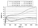
Arガス流量/N2ガス流量を変化させた窒化クロム膜を窒化シリコン(SiNx)で挟みこんだ構成(サンプルB1〜B6)の分光透過率を図3に示す。また、物性値を表3に示す。
比較例であるサンプルB1およびB2では、可視光領域における分光透過率に比べて、可視光領域よりも長波側における分光透過率が、全体的に大きくなっている。サンプルB1およびB2に対し、サンプルB3〜B5では、可視光領域における分光透過率と、可視光領域よりも長波側分光透過率とが、全体的に見れば略同等の透過率となっている。ただし、長波長側の波長領域のうち特に近赤外領域(波長範囲約1000nm〜1300nm)に注目すると、特にサンプルB3およびB4では、可視光領域における分光透過率に比べて、近赤外領域における分光透過率が顕著に低い。B6では可視透過率が部分が、近赤外領域部分より低くなっている。
なお、これらのサンプルB3〜B5は、加熱処理後の光学特性の確認は行っていないが、B4サンプルはほぼ実施例1のサンプルと等しいために、B3〜B5の加熱処理後の光学特性は実施例1と同様に光学特性(Te/Tv)の変化がないと考えている。
FIG. 3 shows the spectral transmittance of a configuration (samples B 1 to B 6 ) in which a chromium nitride film with varying Ar gas flow rate / N 2 gas flow rate is sandwiched between silicon nitride (SiNx). The physical property values are shown in Table 3.
Sample B 1 and B 2 is a comparative example, in comparison with the spectral transmittance in the visible light region, the spectral transmittance in the long wave side of visible light region, it is generally larger. In contrast to samples B 1 and B 2 , in samples B 3 to B 5 , the spectral transmittance in the visible light region and the spectral transmittance on the longer wave side than the visible light region are substantially equal to each other. It has become. However, focusing on the near-infrared region (wavelength range of about 1000 nm to 1300 nm) in the wavelength region on the long wavelength side, particularly in the samples B 3 and B 4 , the near-infrared region is compared with the spectral transmittance in the visible light region. The spectral transmittance in the region is significantly low. B 6 In the visible transmittance of the portion is lower than the near-infrared region portion.
Note that these samples B 3 .about.B 5 is not done confirmation of optical properties after the heat treatment, B 4 to sample approximately equal to Example 1 sample, after the heat treatment B 3 .about.B 5 As in Example 1, it is considered that there is no change in the optical characteristics (T e / T v ).
上述したとおり、上記JIS規格で定義される可視光透過率Tvは、可視光領域(波長範囲380nm〜780nm)における分光透過率の程度をよく反映し、同じくJIS規格で定義される日射透過率は、特に近赤外領域(波長範囲1000nm〜1300nm)における分光透過率の程度をよく反映しているといえる。日射透過率Te/可視光透過率Tvを求めた場合、比較例であるサンプルB1およびB2に対し、サンプルB3〜B5の日射透過率Te/可視光透過率Tvは比較的小さい値を示し、特に、サンプルB3およびサンプルB4において少なくとも1.0未満になる。
可視光透過率Tvが一定(14%)になるような条件で、日射透過率Te/可視光透過率Tvについてもとめたシミュレーションによる計算値を表4に示す。可視光透過率Tvを一定(14%)にするためには窒化クロム膜の膜厚を変え、窒化シリコン(SiNx)からなる酸素遮断下地膜(10nm)、窒化シリコンからなる酸素遮断保護膜(20nm)の膜厚は固定した。 Table 4 shows the calculated values by simulation for the solar radiation transmittance T e / visible light transmittance T v under the condition that the visible light transmittance T v is constant (14%). In order to make the visible light transmittance Tv constant (14%), the film thickness of the chromium nitride film is changed, and an oxygen blocking base film (10 nm) made of silicon nitride (SiNx), an oxygen blocking protective film made of silicon nitride ( The film thickness of 20 nm) was fixed.
表4に示すサンプルC1〜C6は、図1(a)に示す熱線反射ガラス10と同様の構成の熱線反射ガラスを想定し、図2に示す分光透過率の実測値と、公知であるSiNx膜(酸素遮断下地膜と酸素遮断保護膜)の分光透過率と、公知であるガラス基板の分光透過率と、を用いて、上記JIS規格で規定される日射透過率Teおよび可視光透過率Tvをそれぞれ計算したときの値を示す。なお、サンプルC4の計算値は、上記実施例1の実測した熱線反射ガラスと同じ膜厚、ガス比の条件のときのシミュレーション(計算)により求めた値である。
Samples C 1 to C 6 shown in Table 4 are assumed to be heat ray reflective glasses having the same configuration as the heat ray
表3、表4の結果を図4、図5に示す。図4では窒化クロム膜中の、クロム原子数に対する窒素原子数の割合(N/Cr)が20%〜60%(グラフ上の表示では、0.2〜0.6)である場合、日射透過率Te/可視光透過率Tvは0.95以下になっている。またこの範囲では日射透過率Te/可視光透過率Tvの変動は少なく、クロム原子数に対する窒素原子数の割合(N/Cr)の変動に対して日射透過率Te/可視光透過率Tvが安定であることがわかった。
また図5では、窒化クロム膜を反応性スパッタリングによって作製する際、N2ガスとArガスとの流量(単位時間あたりの流入量)の比を、(Ar:N2)=(70:30)〜(90:10)のとき、日射透過率Te/可視光透過率Tvは0.95以下になっている。またこの範囲では日射透過率Te/可視光透過率Tvの変動は少なく、N2ガスとArガスとの流量の変動に対して日射透過率Te/可視光透過率Tvが安定であることがわかった。
これらより、本発明でクロム原子数に対する窒素原子数の割合(N/Cr)が20%〜60%にすることにより、または、窒化クロム膜を(Ar:N2)=(70:30)〜(90:10)で反応性スパッタリングすることにより、可視光透過率Tvが35%以下、かつ日射透過率Te/可視光透過率Tvが1.0未満の性能をもつ熱線反射ガラスを得ることができ、また窒化クロム膜の成膜の条件の変動に対して、日射透過率Te/可視光透過率Tvの変動が少なくできることがわかった。
The results of Tables 3 and 4 are shown in FIGS. In FIG. 4, when the ratio of the number of nitrogen atoms to the number of chromium atoms (N / Cr) in the chromium nitride film is 20% to 60% (in the display on the graph, 0.2 to 0.6), the solar radiation is transmitted. The ratio T e / visible light transmittance T v is 0.95 or less. Further, in this range, the variation in solar transmittance T e / visible light transmittance T v is small, and the solar transmittance T e / visible light transmittance with respect to the variation in the ratio of the number of nitrogen atoms to the number of chromium atoms (N / Cr). T v has been found to be stable.
Further, in FIG. 5, when the chromium nitride film is formed by reactive sputtering, the ratio of the flow rate (inflow per unit time) of N 2 gas and Ar gas is (Ar: N 2 ) = (70:30). At (90:10), the solar radiation transmittance T e / visible light transmittance T v is 0.95 or less. In this range, the variation of the solar transmittance T e / visible light transmittance T v is small, and the solar transmittance T e / visible light transmittance T v is stable with respect to the fluctuation of the flow rate of N 2 gas and Ar gas. I found out.
From these, the ratio of the number of nitrogen atoms to the number of chromium atoms (N / Cr) in the present invention is set to 20% to 60%, or the chromium nitride film is made (Ar: N 2 ) = (70:30) to by reactive sputtering with (90:10) the visible light transmittance T v of 35% or less, and solar transmittance T e / visible light transmittance T v is a heat reflecting glass having less than 1.0 performance It was also found that the variation of the solar transmittance T e / visible light transmittance T v can be reduced with respect to the variation of the film forming conditions of the chromium nitride film.
なお、図6には、ガス流量条件(Ar:N2)=(80:20)で窒化クロム膜(CrNx)の膜厚を変化させて成膜した、複数のサンプルD1〜D5のそれぞれの、分光透過率のスペクトルを示している。サンプルD1〜D5の各サンプルは、サンプルC4の成膜条件と、それぞれ窒化クロム膜(CrNx)の膜厚のみが異なっている。すなわち、図6に示す各サンプルD1〜D5は、いずれも、Arガス流量/N2ガス流量を(Ar:N2)=(80:20)に設定して作製され、窒化クロム膜における原子数の割合(N/Cr)がいずれも0.41である。なお、図6のグラフに示す膜厚は、事前に調べた成膜レートを用い計測した値から事前に計算した成膜時間でおこなった。 In FIG. 6, each of a plurality of samples D 1 to D 5 formed by changing the film thickness of the chromium nitride film (CrNx) under the gas flow rate condition (Ar: N 2 ) = (80:20). The spectrum of the spectral transmittance is shown. Each of the samples D 1 to D 5 differs only in the film formation conditions of the sample C 4 and the film thickness of the chromium nitride film (CrNx). That is, each of the samples D 1 to D 5 shown in FIG. 6 is produced by setting the Ar gas flow rate / N 2 gas flow rate to (Ar: N 2 ) = (80:20), and the chromium nitride film The ratio of the number of atoms (N / Cr) is 0.41. In addition, the film thickness shown in the graph of FIG. 6 was performed by the film-forming time calculated in advance from the value measured using the film-forming rate investigated in advance.
図6に示すように、窒化クロム膜における、クロム原子に対する窒素原子の割合(N/Cr)がいずれもほぼ同等の場合、窒化クロム膜の膜厚が変わっても、分光透過率の大まかな傾向は特に変化しない。窒化クロム膜において、日射透過率Te/可視光透過率Tvは、窒化クロム膜におけるクロム原子に対するN2原子の割合(N/Cr)、ひいては、反応性スパッタリングにおけるArガス流量/N2ガス流量、によって決定づけられており、膜厚は寄与していない。逆にいえば、窒化クロム膜の膜厚を変化させるだけでも、分光透過率のスペクトルを全体的に低下させることができ、可視光透過率の絶対値や日射透過率の絶対値を低減させることができるが、窒化クロム膜の膜厚を変化させるだけでは、可視光透過率に対する日射透過率の比を調整することはできない。本願発明者は、このような知見を初めて見出し、本発明に至っている。
表5は、図6に示すの分光透過率の値から求めた物性値を示す。日射透過率Te/可視光透過率Tvは、窒化クロム膜の膜厚が変化しても同じである。サンプルD1〜D5では、可視透過率Tvが約10%〜約20%の範囲で、ビルなどの室内に居る人物が感じる眩しさや、外から中が見え無いプライバシー性が十分であり、かつ、日射透過率Te/可視光透過率Tvが0.87と低く、室内への熱の流入を防ぐという効果がある。
Table 5 shows physical property values obtained from the spectral transmittance values shown in FIG. The solar transmittance T e / visible light transmittance T v is the same even when the film thickness of the chromium nitride film changes. Sample D 1 to D 5, the range visible transmission T v is from about 10% to about 20%, glare or the person feel in the room such as a building, privacy of the not visible medium from outside is sufficient, Moreover, the solar radiation transmittance T e / visible light transmittance T v is as low as 0.87, which has an effect of preventing heat from flowing into the room.
本発明の熱線反射ガラスでは、ガラス基板に形成する層の構成は、上述の各実施形態に限定されるものではない。例えば、熱線反射用の窒化クロム膜に進入する酸素を、より高精度に防ぐために、図1に示す実施形態の最上層である酸素遮断保護膜の上層に、さらに第2の保護膜を設けてもよい。第2の保護膜としては、例えば、金属酸化物からなり、可視光領域において透明な膜であり、酸素バリア性の高いものが好ましい。具体的には、酸化スズ、酸化タンタル、酸化ニオブ、酸化チタン、酸化ケイ素、酸化ジルコニウム、酸化亜鉛などが挙げられる。かかる第2の保護膜の厚さは、熱線反射ガラスが有すべき酸素遮断性能や光学特性などを考慮して決定すればよい。また、この第2の保護膜以外の層も、必要に応じて設けていても構わない。 In the heat ray reflective glass of this invention, the structure of the layer formed in a glass substrate is not limited to each above-mentioned embodiment. For example, in order to prevent oxygen entering the chromium nitride film for heat ray reflection with higher accuracy, a second protective film is further provided on the upper layer of the oxygen blocking protective film which is the uppermost layer in the embodiment shown in FIG. Also good. The second protective film is preferably made of, for example, a metal oxide, is a transparent film in the visible light region, and has a high oxygen barrier property. Specific examples include tin oxide, tantalum oxide, niobium oxide, titanium oxide, silicon oxide, zirconium oxide, and zinc oxide. The thickness of the second protective film may be determined in consideration of oxygen blocking performance and optical characteristics that the heat ray reflective glass should have. Further, layers other than the second protective film may be provided as necessary.
以上、本発明の熱線反射ガラス及び熱線反射ガラスの製造方法について詳細に説明したが、本発明は上記実施形態や実施例に限定されず、本発明の主旨を逸脱しない範囲において、種々の改良や変更をしてもよいのはもちろんである。 As mentioned above, although the heat ray reflective glass of this invention and the manufacturing method of heat ray reflective glass were demonstrated in detail, this invention is not limited to the said embodiment and Example, In the range which does not deviate from the main point of this invention, various improvement and Of course, changes may be made.
10、20 熱線反射ガラス
12 ガラス基板
14 窒化クロム(CrNx)膜
16 酸素遮断下地膜
17 不純物遮断下地膜
18 酸素遮断保護膜
DESCRIPTION OF
Claims (7)
前記窒化クロム膜における、クロムに対する窒素の原子数の割合(窒素原子数/クロム原子数)が、20%〜60%であることを特徴とする熱線反射ガラス。 A glass substrate is provided with an oxygen blocking base film, a chromium nitride film and an oxygen blocking protective film in this order,
The ratio of the number of nitrogen atoms to the chromium (the number of nitrogen atoms / the number of chromium atoms) in the chromium nitride film is 20% to 60%.
ガラス基板を成膜チャンバ内に導入し、前記チャンバ内を窒素含有雰囲気としてクロムターゲットをスパッタリングすることで、前記ガラス基板に、窒化クロム膜を設ける工程と、
前記スパッタリングの最中、前記チャンバ内に、窒素ガスを流入させるとともに、前記窒素ガス以外の不活性ガスを流入させ、前記不活性ガスの流入量の比を、(不活性ガス:窒素ガス)=(70:30)〜(90:10)の範囲に調整する工程と、
を有することを特徴とする熱線反射ガラスの製造方法。 A method for producing a heat ray reflective glass in which an oxygen blocking base film, a chromium nitride film and an oxygen blocking protective film are provided in this order on a glass substrate,
Providing a chromium nitride film on the glass substrate by introducing a glass substrate into the deposition chamber and sputtering a chromium target with the chamber containing a nitrogen-containing atmosphere;
During the sputtering, nitrogen gas is allowed to flow into the chamber and an inert gas other than the nitrogen gas is allowed to flow, and the ratio of the inflow amount of the inert gas is (inert gas: nitrogen gas) = Adjusting to a range of (70:30) to (90:10);
The manufacturing method of the heat ray reflective glass characterized by having.
前記スパッタリングの後、前記窒化クロム膜の表面に、ケイ素またはホウ素の窒化物を主成分とする膜、あるいは、ケイ素、ホウ素、アルミニウム、ジルコニウム、スズからなる群から選ばれる2種以上の元素の窒化物を主成分とする膜、とする酸素遮断保護膜を設ける工程と、を有することを特徴とする請求項5記載の熱線反射ガラスの製造方法。 Prior to the sputtering, a film containing silicon or boron nitride as a main component or a nitride of two or more elements selected from the group consisting of silicon, boron, aluminum, zirconium and tin is formed on the glass substrate. A step of providing an oxygen-blocking base film, which is a main component film;
After the sputtering, on the surface of the chromium nitride film, a film containing silicon or boron nitride as a main component, or nitriding two or more elements selected from the group consisting of silicon, boron, aluminum, zirconium and tin A method for producing a heat ray reflective glass according to claim 5, further comprising a step of providing an oxygen-blocking protective film comprising a film containing an object as a main component.
500℃以上に熱処理することを特徴とする請求項6記載の熱線反射ガラスの製造方法。 After providing the oxygen blocking base film, the chromium nitride film, and the oxygen blocking protective film,
The method for producing a heat ray reflective glass according to claim 6, wherein the heat treatment is performed at 500 ° C. or higher.
Priority Applications (7)
| Application Number | Priority Date | Filing Date | Title |
|---|---|---|---|
| JP2007336133A JP2009155169A (en) | 2007-12-27 | 2007-12-27 | Heat-ray reflecting glass and method for manufacturing heat-ray reflecting glass |
| KR1020107011043A KR20100097115A (en) | 2007-12-27 | 2008-12-17 | Heat reflecting glass and process for producing heat reflecting glass |
| CN2008801231985A CN101910083A (en) | 2007-12-27 | 2008-12-17 | Heat reflecting glass and process for producing heat reflecting glass |
| SG2012095568A SG187398A1 (en) | 2007-12-27 | 2008-12-17 | Heat reflecting glass and process for producing heat reflecting glass |
| PCT/JP2008/073013 WO2009084442A1 (en) | 2007-12-27 | 2008-12-17 | Heat reflecting glass and process for producing heat reflecting glass |
| EP08868954A EP2226305A4 (en) | 2007-12-27 | 2008-12-17 | Heat reflecting glass and process for producing heat reflecting glass |
| US12/820,295 US20100255294A1 (en) | 2007-12-27 | 2010-06-22 | Heat reflecting glass and process for producing heat reflecting glass |
Applications Claiming Priority (1)
| Application Number | Priority Date | Filing Date | Title |
|---|---|---|---|
| JP2007336133A JP2009155169A (en) | 2007-12-27 | 2007-12-27 | Heat-ray reflecting glass and method for manufacturing heat-ray reflecting glass |
Publications (1)
| Publication Number | Publication Date |
|---|---|
| JP2009155169A true JP2009155169A (en) | 2009-07-16 |
Family
ID=40824162
Family Applications (1)
| Application Number | Title | Priority Date | Filing Date |
|---|---|---|---|
| JP2007336133A Withdrawn JP2009155169A (en) | 2007-12-27 | 2007-12-27 | Heat-ray reflecting glass and method for manufacturing heat-ray reflecting glass |
Country Status (7)
| Country | Link |
|---|---|
| US (1) | US20100255294A1 (en) |
| EP (1) | EP2226305A4 (en) |
| JP (1) | JP2009155169A (en) |
| KR (1) | KR20100097115A (en) |
| CN (1) | CN101910083A (en) |
| SG (1) | SG187398A1 (en) |
| WO (1) | WO2009084442A1 (en) |
Cited By (4)
| Publication number | Priority date | Publication date | Assignee | Title |
|---|---|---|---|---|
| WO2016167115A1 (en) * | 2015-04-14 | 2016-10-20 | 株式会社シンク・ラボラトリー | Gravure cylinder and manufacturing method thereof |
| JP2017102475A (en) * | 2017-02-06 | 2017-06-08 | 旭硝子株式会社 | Reflection type mask blank for euv lithography and reflection type mask for euv lithography |
| JP2018106183A (en) * | 2018-02-07 | 2018-07-05 | 旭硝子株式会社 | Reflection type mask blank for euv lithography, and, reflection type mask for euv lithography |
| JP7358955B2 (en) | 2019-12-06 | 2023-10-11 | 株式会社デンソー | laser ignition device |
Families Citing this family (8)
| Publication number | Priority date | Publication date | Assignee | Title |
|---|---|---|---|---|
| CN102560339B (en) * | 2010-12-13 | 2015-10-14 | 鸿富锦精密工业(深圳)有限公司 | Film-coated part and preparation method thereof |
| US9150003B2 (en) | 2012-09-07 | 2015-10-06 | Guardian Industries Corp. | Coated article with low-E coating having absorbing layers for low film side reflectance and low visible transmission |
| EP2980919B1 (en) * | 2013-03-27 | 2017-11-29 | Asahi Glass Company, Limited | Windshield and antenna |
| EP3106196B1 (en) | 2014-04-01 | 2019-09-18 | Terumo Kabushiki Kaisha | Positioning method for balloon coating |
| EP2977202A1 (en) * | 2014-07-25 | 2016-01-27 | AGC Glass Europe | Heating glass |
| EP3172175B1 (en) * | 2014-07-25 | 2023-01-11 | AGC Glass Europe | Decorative glass panel |
| JP6423198B2 (en) * | 2014-08-05 | 2018-11-14 | 日東電工株式会社 | Infrared reflective film |
| FR3065211A1 (en) * | 2017-04-12 | 2018-10-19 | Saint-Gobain Glass France | REFLECTIVE GLAZING COMPRISING A SILICON NITRIDE THIN FILM RICH IN SILICON |
Citations (3)
| Publication number | Priority date | Publication date | Assignee | Title |
|---|---|---|---|---|
| JPH0867980A (en) * | 1993-07-28 | 1996-03-12 | Asahi Glass Co Ltd | Production of silicon nitride film |
| US20030180546A1 (en) * | 2001-05-03 | 2003-09-25 | Guardian Industries Corp. | Heat treatable coated article with chromium nitride IR reflecting layer and method of making same |
| US20040197574A1 (en) * | 2003-04-03 | 2004-10-07 | Grzegorz Stachowiak | Coated article with dual-layer protective overcoat of nitride and zirconium or chromium oxide |
Family Cites Families (11)
| Publication number | Priority date | Publication date | Assignee | Title |
|---|---|---|---|---|
| JPS5826051A (en) * | 1981-08-06 | 1983-02-16 | Asahi Glass Co Ltd | Glass body having formed alkali diffusion preventing silicon oxide film |
| JPH0597475A (en) * | 1991-10-04 | 1993-04-20 | Central Glass Co Ltd | Bent heat insulating glass and its production |
| JP2518129B2 (en) | 1991-10-30 | 1996-07-24 | 旭硝子株式会社 | Heat-treated coated glass and method for producing the same |
| JPH05124839A (en) * | 1991-10-31 | 1993-05-21 | Central Glass Co Ltd | Heat insulating glass which can be thermally worked |
| JPH05238778A (en) * | 1992-02-24 | 1993-09-17 | Central Glass Co Ltd | Heat ray shielding glass having radio wave low-reflection characteristic |
| EP0905273B1 (en) * | 1993-07-28 | 2002-10-16 | Asahi Glass Company Ltd. | Method for producing films |
| JPH08151233A (en) * | 1994-11-24 | 1996-06-11 | Asahi Glass Co Ltd | Transparent heating body |
| JP2001328847A (en) * | 2000-05-19 | 2001-11-27 | Central Glass Co Ltd | Heat-reflective glass having high durability |
| JP2002047033A (en) * | 2000-08-01 | 2002-02-12 | Central Glass Co Ltd | Heatwave shuttering glass capable of thermal treatment |
| US6524714B1 (en) * | 2001-05-03 | 2003-02-25 | Guardian Industries Corp. | Heat treatable coated articles with metal nitride layer and methods of making same |
| JP2003002691A (en) * | 2001-06-19 | 2003-01-08 | Central Glass Co Ltd | Low reflective substrate and method for producing the same |
-
2007
- 2007-12-27 JP JP2007336133A patent/JP2009155169A/en not_active Withdrawn
-
2008
- 2008-12-17 WO PCT/JP2008/073013 patent/WO2009084442A1/en active Application Filing
- 2008-12-17 CN CN2008801231985A patent/CN101910083A/en active Pending
- 2008-12-17 KR KR1020107011043A patent/KR20100097115A/en not_active Application Discontinuation
- 2008-12-17 EP EP08868954A patent/EP2226305A4/en not_active Withdrawn
- 2008-12-17 SG SG2012095568A patent/SG187398A1/en unknown
-
2010
- 2010-06-22 US US12/820,295 patent/US20100255294A1/en not_active Abandoned
Patent Citations (3)
| Publication number | Priority date | Publication date | Assignee | Title |
|---|---|---|---|---|
| JPH0867980A (en) * | 1993-07-28 | 1996-03-12 | Asahi Glass Co Ltd | Production of silicon nitride film |
| US20030180546A1 (en) * | 2001-05-03 | 2003-09-25 | Guardian Industries Corp. | Heat treatable coated article with chromium nitride IR reflecting layer and method of making same |
| US20040197574A1 (en) * | 2003-04-03 | 2004-10-07 | Grzegorz Stachowiak | Coated article with dual-layer protective overcoat of nitride and zirconium or chromium oxide |
Cited By (8)
| Publication number | Priority date | Publication date | Assignee | Title |
|---|---|---|---|---|
| WO2016167115A1 (en) * | 2015-04-14 | 2016-10-20 | 株式会社シンク・ラボラトリー | Gravure cylinder and manufacturing method thereof |
| KR20170092598A (en) * | 2015-04-14 | 2017-08-11 | 가부시키가이샤 씽크. 라보라토리 | Gravure cylinder and manufacturing method thereof |
| JPWO2016167115A1 (en) * | 2015-04-14 | 2018-02-08 | 株式会社シンク・ラボラトリー | Gravure cylinder and manufacturing method thereof |
| TWI671207B (en) * | 2015-04-14 | 2019-09-11 | 日商新克股份有限公司 | Gravure cylinder and method for producing the same |
| KR102026762B1 (en) | 2015-04-14 | 2019-09-30 | 가부시키가이샤 씽크. 라보라토리 | Gravure cylinder and manufacturing method thereof |
| JP2017102475A (en) * | 2017-02-06 | 2017-06-08 | 旭硝子株式会社 | Reflection type mask blank for euv lithography and reflection type mask for euv lithography |
| JP2018106183A (en) * | 2018-02-07 | 2018-07-05 | 旭硝子株式会社 | Reflection type mask blank for euv lithography, and, reflection type mask for euv lithography |
| JP7358955B2 (en) | 2019-12-06 | 2023-10-11 | 株式会社デンソー | laser ignition device |
Also Published As
| Publication number | Publication date |
|---|---|
| EP2226305A4 (en) | 2011-04-13 |
| CN101910083A (en) | 2010-12-08 |
| KR20100097115A (en) | 2010-09-02 |
| US20100255294A1 (en) | 2010-10-07 |
| WO2009084442A1 (en) | 2009-07-09 |
| SG187398A1 (en) | 2013-02-28 |
| EP2226305A1 (en) | 2010-09-08 |
Similar Documents
| Publication | Publication Date | Title |
|---|---|---|
| WO2009084442A1 (en) | Heat reflecting glass and process for producing heat reflecting glass | |
| JP6181210B2 (en) | Sheet glass with thermal radiation reflective coating | |
| TWI289139B (en) | Reflective, solar control coated glass article | |
| JP5426577B2 (en) | Solar protective glass with improved light transmission | |
| JP7025665B2 (en) | Sunlight shielding member | |
| JP2888507B2 (en) | Metal vacuum-coated article and method for producing the same | |
| JP6328122B2 (en) | Low emissivity coated products with low visible light transmission | |
| JP4298654B2 (en) | Quenchable high light-shielding coating | |
| CN102378682A (en) | Thin film coating and method of making the same | |
| JP5824046B2 (en) | Glass panel with solar shading properties | |
| JP2000129464A (en) | Transparent substrate provided with thin-film stack | |
| EP3560700A1 (en) | Low-emissivity coating for a glass substrate | |
| WO2014191472A2 (en) | Low-emissivity glazing | |
| MX2007011247A (en) | Coating composition with solar properties. | |
| JP5325100B2 (en) | Glass article having zinc oxide coating and method for producing the same | |
| AU2016397940A1 (en) | Bronze colored heat treatable coated article having low solar factor value | |
| JP6853486B2 (en) | Solar shielding member | |
| JP6767661B2 (en) | Gray tones low emissivity glass | |
| CN109562986A (en) | Green with low sun factor values can be heat-treated coating product | |
| JP7380708B2 (en) | door or wall | |
| WO2016060083A1 (en) | Window glass and transparent substrate provided with layered film | |
| JP2003002691A (en) | Low reflective substrate and method for producing the same | |
| WO2020083691A1 (en) | Low reflectance solar control glazing | |
| JP2019182684A (en) | Low radiation glass | |
| JP2019081694A (en) | Transparent substrate with laminate film, and window glass |
Legal Events
| Date | Code | Title | Description |
|---|---|---|---|
| A621 | Written request for application examination |
Free format text: JAPANESE INTERMEDIATE CODE: A621 Effective date: 20100816 |
|
| A131 | Notification of reasons for refusal |
Free format text: JAPANESE INTERMEDIATE CODE: A131 Effective date: 20130212 |
|
| A761 | Written withdrawal of application |
Free format text: JAPANESE INTERMEDIATE CODE: A761 Effective date: 20130326 |