JP6171478B2 - Storage system, information processing apparatus, control program for information processing apparatus, and control method for information processing apparatus - Google Patents
Storage system, information processing apparatus, control program for information processing apparatus, and control method for information processing apparatus Download PDFInfo
- Publication number
- JP6171478B2 JP6171478B2 JP2013069341A JP2013069341A JP6171478B2 JP 6171478 B2 JP6171478 B2 JP 6171478B2 JP 2013069341 A JP2013069341 A JP 2013069341A JP 2013069341 A JP2013069341 A JP 2013069341A JP 6171478 B2 JP6171478 B2 JP 6171478B2
- Authority
- JP
- Japan
- Prior art keywords
- data
- parity
- storage
- area
- data areas
- Prior art date
- Legal status (The legal status is an assumption and is not a legal conclusion. Google has not performed a legal analysis and makes no representation as to the accuracy of the status listed.)
- Expired - Fee Related
Links
Images


Classifications
-
- G—PHYSICS
- G06—COMPUTING; CALCULATING OR COUNTING
- G06F—ELECTRIC DIGITAL DATA PROCESSING
- G06F11/00—Error detection; Error correction; Monitoring
- G06F11/07—Responding to the occurrence of a fault, e.g. fault tolerance
- G06F11/08—Error detection or correction by redundancy in data representation, e.g. by using checking codes
- G06F11/10—Adding special bits or symbols to the coded information, e.g. parity check, casting out 9's or 11's
- G06F11/1076—Parity data used in redundant arrays of independent storages, e.g. in RAID systems
-
- G—PHYSICS
- G06—COMPUTING; CALCULATING OR COUNTING
- G06F—ELECTRIC DIGITAL DATA PROCESSING
- G06F2211/00—Indexing scheme relating to details of data-processing equipment not covered by groups G06F3/00 - G06F13/00
- G06F2211/10—Indexing scheme relating to G06F11/10
- G06F2211/1002—Indexing scheme relating to G06F11/1076
- G06F2211/1028—Distributed, i.e. distributed RAID systems with parity
-
- G—PHYSICS
- G06—COMPUTING; CALCULATING OR COUNTING
- G06F—ELECTRIC DIGITAL DATA PROCESSING
- G06F3/00—Input arrangements for transferring data to be processed into a form capable of being handled by the computer; Output arrangements for transferring data from processing unit to output unit, e.g. interface arrangements
- G06F3/06—Digital input from, or digital output to, record carriers, e.g. RAID, emulated record carriers or networked record carriers
- G06F3/0601—Interfaces specially adapted for storage systems
- G06F3/0602—Interfaces specially adapted for storage systems specifically adapted to achieve a particular effect
- G06F3/0604—Improving or facilitating administration, e.g. storage management
- G06F3/0605—Improving or facilitating administration, e.g. storage management by facilitating the interaction with a user or administrator
Description
本発明は、ストレージシステム、情報処理装置、情報処理装置の制御プログラム、および情報処理装置の制御方法に関する。 The present invention relates to a storage system, an information processing apparatus, a control program for the information processing apparatus, and a control method for the information processing apparatus.
分散ストレージシステムなどのストレージシステムは、生成直後のデータに対するアクセス頻度が高い。そのため、ストレージシステムは、データを複製し、複数のストレージノードに複製したデータを分散して配置することによりデータの可用性および信頼性を確保するレプリケーションをおこなっている。 A storage system such as a distributed storage system has a high access frequency to data immediately after generation. Therefore, the storage system performs replication to ensure data availability and reliability by replicating data and distributing and distributing the replicated data to a plurality of storage nodes.
しかしながら、レプリケーションは、ストレージオーバヘッドが大きい(容量効率が悪い)。そのため、ストレージシステムは、アクセス頻度が落ち着いたタイミングを見計らって、レプリケーションからストレージオーバヘッドが小さいRAID(Redundant Arrays of Independent Disks)へと移行する。 However, replication has a large storage overhead (capacity efficiency is poor). For this reason, the storage system shifts from replication to RAID (Redundant Arrays of Independent Disks) with a small storage overhead at the timing when the access frequency is settled.
レプリケーションからRAIDへの移行は、パリティ計算のためのデータ読み込みの他にノード間におけるデータ転送をおこなわなければならず、ユーザ業務に影響を与えることがあった。また、レプリケーションからRAIDへの移行過程において、一時的にレプリケーションとRAIDとが共存することでストレージリソースの余計な消費があった。 The migration from replication to RAID has to perform data transfer between nodes in addition to reading data for parity calculation, which may affect user operations. Further, in the process of transition from replication to RAID, there is an extra consumption of storage resources due to the temporary coexistence of replication and RAID.
このような問題に対して、条件に応じてストレージノード間におけるデータ転送なしにレイドレベルを変更可能なディスクアレイ装置が知られている。 To deal with such a problem, a disk array device is known that can change the raid level without transferring data between storage nodes according to conditions.
しかしながら、依然としてレプリケーションからRAIDへの移行は、ストレージノード間におけるデータ転送を生じるものであり、ユーザ業務に与える影響を軽減する余地がある。 However, the transition from replication to RAID still causes data transfer between storage nodes, and there is room for reducing the impact on user operations.
1つの側面では、本発明は、ストレージノード間におけるデータ転送なしにレプリケーションからRAIDへの移行をおこなうことができるストレージシステム、情報処理装置、情報処理装置の制御プログラム、および情報処理装置の制御方法を提供することを目的とする。 In one aspect, the present invention provides a storage system, an information processing apparatus, an information processing apparatus control program, and an information processing apparatus control method capable of performing a transition from replication to RAID without transferring data between storage nodes. The purpose is to provide.
上記目的を達成するために、以下に示すような、ストレージシステムが提供される。ストレージシステムは、情報処理装置と、複数のストレージノードとを備える。ストレージノードは、複数のデータ領域と、複数のデータ領域に対応するパリティ領域とを有する。情報処理装置は、複製部と、パリティ生成部と、データ選択部と、を有する。複製部は、複数のストレージノードのうち一のストレージノードが複数のデータ領域に記憶する複数のデータをそれぞれ複製し、他のストレージノードが有する複数のデータ領域にそれぞれ記憶する。パリティ生成部は、ストレージノードごとに、複数のデータ領域がそれぞれ記憶するデータに対応するパリティを生成してパリティ領域に記憶する。データ選択部は、複数のストレージノードが有する複数のデータ領域にそれぞれ記憶されたデータの多重度が低下するように、ストレージノード単体に属する複数のデータ領域のうちデータを保持するデータ領域の選択およびその余のデータ領域の解放を、複数のストレージノードそれぞれに対して実行する。 In order to achieve the above object, a storage system as shown below is provided. The storage system includes an information processing apparatus and a plurality of storage nodes. The storage node has a plurality of data areas and a parity area corresponding to the plurality of data areas. The information processing apparatus includes a duplication unit, a parity generation unit, and a data selection unit. The duplication unit duplicates a plurality of data stored in a plurality of data areas by one storage node among the plurality of storage nodes, and stores the data in a plurality of data areas of other storage nodes. The parity generation unit generates parity corresponding to data stored in each of the plurality of data areas for each storage node, and stores the parity in the parity area. Data selection unit, as each multiplicity of stored data into a plurality of data areas in which a plurality of storage nodes have is lowered, the selection of the data area for holding data of the plurality of data areas belonging to a single storage node and The remaining data area is released to each of the plurality of storage nodes .
1態様によれば、ストレージシステム、情報処理装置、情報処理装置の制御プログラム、および情報処理装置の制御方法において、ストレージノード間におけるデータ転送なしにレプリケーションからRAIDへの移行をおこなうことができる。 According to one aspect, in a storage system, an information processing apparatus, an information processing apparatus control program, and an information processing apparatus control method, a transition from replication to RAID can be performed without data transfer between storage nodes.
以下、実施の形態を図面を参照して詳細に説明する。
[第1の実施形態]
まず、第1の実施形態のストレージシステムについて図1を用いて説明する。図1は、第1の実施形態のストレージシステムの構成の一例を示す図である。
Hereinafter, embodiments will be described in detail with reference to the drawings.
[First Embodiment]
First, the storage system of the first embodiment will be described with reference to FIG. FIG. 1 is a diagram illustrating an example of a configuration of a storage system according to the first embodiment.
ストレージシステム1は、分散ストレージシステムであり、レプリケーションやRAIDにより可用性および信頼性を確保する。ストレージシステム1は、生成直後のデータに対してレプリケーションをおこなうが、ストレージオーバヘッドが大きいことから時機をみてRAIDへの移行をおこなう。
The
ストレージシステム1は、情報処理装置2と複数のストレージノード6(6a,6b,6c,6d)を備える。ストレージノード6は、データ領域8と、パリティ領域7を備える。ストレージノード6は、複数のデータ領域8にデータを保持し、複数のデータ領域8に対応するパリティをパリティ領域7に保持する。
The
情報処理装置2は、ストレージノード6を管理する管理ノードである。情報処理装置2は、複数のストレージノード6を内蔵してもよいし、複数のストレージノード6と図示しないネットワークにより外部接続するものであってもよい。また、情報処理装置2は、ストレージノード6ごとに設けられるものであってもよく、その場合、情報処理装置2の1つがマスタとなり、その余がスレーブとなって複数のストレージノード6を管理してもよいし、複数の情報処理装置2が協働して複数のストレージノード6を管理してもよい。
The
情報処理装置2は、複製部3と、パリティ生成部4と、データ選択部5を備える。複製部3は、ストレージシステム1におけるデータの複製(レプリケーション)をおこなう。複製部3は、ストレージノード6a,6b,6c,6dのうちの1つ(たとえば、ストレージノード6a)が複数のデータ領域8に記憶する複数のデータD0,D1,D2,D3をそれぞれ複製する。複製部3は、複製したデータD0,D1,D2,D3を、他のストレージノード6(たとえば、ストレージノード6b,6c,6d)が有する複数のデータ領域8にそれぞれ記憶する。すなわち、複製部3は、ストレージノード6a,6b,6c,6dのそれぞれのデータ領域8にデータD0,D1,D2,D3を保持させる。これにより、ストレージシステム1は、データD0,D1,D2,D3についてそれぞれ4重のレプリケーションを実現する。
The
パリティ生成部4は、ストレージノード6ごとに、複数のデータ領域8がそれぞれ記憶するデータに対応するパリティを生成する。たとえば、パリティ生成部4は、ストレージノード6aについて、データ領域8が保持するデータD0,D1,D2,D3に対応するパリティP0を生成する。パリティ生成部4は、パリティP0をパリティ領域7に記憶(保持)する。同様にして、パリティ生成部4は、ストレージノード6b,6c,6dについてそれぞれパリティP1,P2,P3を生成し、パリティP1,P2,P3をパリティ領域7に記憶する。なお、パリティP0,P1,P2,P3は、同一のパリティであってもよいし、データD0,D1,D2,D3を分担した異なるパリティであってもよい。
The
データ選択部5は、ストレージノード6ごとに、複数のデータ領域8のうちからデータを保持するデータ領域8を選択し、その余のデータ領域8、すなわち選択しなかったデータ領域8を解放する。解放とは、データ領域8が保持するデータをレプリケーションの対象から外すことであり、データ領域8が保持するデータのクリアを含む。このとき、データ選択部5は、レプリケーションの多重度が低下するように、すなわち、複数のストレージノード6が有する複数のデータ領域8にそれぞれ記憶されたデータの多重度が低下するように選択と解放とをおこなう。
For each
たとえば、データ選択部5は、ストレージノード6aについて、データD0を保持するデータ領域8を選択し、データD1,D2,D3を保持するデータ領域8のデータを解放する。同様にして、データ選択部5は、ストレージノード6b,6c,6dについて、それぞれデータD1,D2,D3を保持するデータ領域8を選択する。このとき、ストレージノード6がデータ領域8に保持するデータをハッチングで示す。
For example, for the
このように、ストレージシステム1は、ストレージノード間におけるデータ転送なしにパリティを生成し、レプリケーションの多重度を低下(たとえば、多重度4から多重度1)させてRAIDへの移行をおこなうことができる。ストレージシステム1は、レプリケーションからRAIDへの移行をおこなう際に、ストレージノード間におけるデータ転送がないことからユーザ業務に与える影響を軽減することができる。
In this way, the
なお、ストレージシステム1は、レプリケーションの多重度を多段階に低下させるようにしてもよい。たとえば、ストレージシステム1は、ある時機にレプリケーションの多重度4を多重度2とし、次の時機にレプリケーションの多重度2を多重度1とする。このようにすれば、ストレージシステム1は、生成直後のデータのアクセス頻度が高い状態から低い状態に漸減して移行する過程に応じたレプリケーションとRAIDとをユーザに提供することができる。
Note that the
[第2の実施形態]
次に、第2の実施形態のストレージシステムの構成について図2を用いて説明する。図2は、第2の実施形態のストレージシステムの構成の一例を示す図である。
[Second Embodiment]
Next, the configuration of the storage system of the second embodiment will be described with reference to FIG. FIG. 2 is a diagram illustrating an example of the configuration of the storage system according to the second embodiment.
ストレージシステム10は、ネットワーク14に計算ノード12を介して接続するストレージノード13を複数備える分散ストレージシステムである。ストレージシステム10は、複数のストレージノード13によりレプリケーションやRAIDにより可用性および信頼性を確保する。
The
ストレージノード13は、1以上のストレージデバイス(たとえば、HDD(Hard Disk Drive)やSSD(Solid State Drive:フラッシュメモリドライブ)など)により構成され、データを保持可能にしている。
The
計算ノード12は、ストレージノード13と接続する。計算ノード12は、論理アドレスでのI/O(Input/Output)要求を受け付けて、論理アドレスに対応するストレージノード13の物理アドレスにアクセスする。ストレージシステム10は、複数の計算ノード12にまたがってレプリケーションやRAIDを構成する。
The
ストレージシステム10は、計算ノード12の1つがマスタとなり、その余がスレーブとなって複数のストレージノード13を管理してレプリケーションやRAIDを構成することができる。なお、ストレージシステム10は、複数の計算ノード12が協働して複数のストレージノード13を管理してレプリケーションやRAIDを構成してもよい。
In the
また、ストレージシステム10は、ネットワーク14を介して計算ノード12と通信可能な管理ノード11を備える。ストレージシステム10は、管理ノード11が計算ノード12を介して複数のストレージノード13を管理してレプリケーションやRAIDを構成してもよい。
The
次に、第2の実施形態の計算ノードのハードウェア構成について図3を用いて説明する。図3は、第2の実施形態の計算ノードのハードウェア構成の一例を示す図である。
計算ノード12は、プロセッサ101によって装置全体が制御されている。プロセッサ101には、バス106を介してRAM(Random Access Memory)102と複数の周辺機器が接続されている。プロセッサ101は、マルチプロセッサであってもよい。プロセッサ101は、たとえばCPU(Central Processing Unit)、MPU(Micro Processing Unit)、DSP(Digital Signal Processor)、ASIC(Application Specific Integrated Circuit)、またはPLD(Programmable Logic Device)である。またプロセッサ101は、CPU、MPU、DSP、ASIC、PLDのうちの2以上の要素の組み合わせであってもよい。
Next, the hardware configuration of the calculation node according to the second embodiment will be described with reference to FIG. FIG. 3 is a diagram illustrating an example of a hardware configuration of a calculation node according to the second embodiment.
The
RAM102は、計算ノード12の主記憶装置として使用される。RAM102には、プロセッサ101に実行させるOS(Operating System)のプログラムやファームウェア、アプリケーションプログラムの少なくとも一部が一時的に格納される。また、RAM102には、プロセッサ101による処理に必要な各種データ(たとえば、システム制御の情報管理)が格納される。また、RAM102は、各種データの格納に用いるメモリと別体にキャッシュメモリを含むものであってもよい。
The
バス106に接続されている周辺機器としては、不揮発性メモリ103、入出力インタフェース104、および通信インタフェース105がある。
不揮発性メモリ103は、計算ノード12の電源遮断時においても記憶内容を保持する。不揮発性メモリ103は、たとえば、EEPROM(Electrically Erasable Programmable Read-Only Memory)やフラッシュメモリなどの半導体記憶装置や、HDDなどである。また、不揮発性メモリ103は、計算ノード12の補助記憶装置として使用される。不揮発性メモリ103には、OSのプログラムやファームウェア、アプリケーションプログラム、および各種データが格納される。
Peripheral devices connected to the
The
入出力インタフェース104は、ストレージノード13などの入出力装置と接続して入出力をおこなう。
通信インタフェース105は、ネットワーク14と接続することで、ネットワーク14を介して、他の計算ノード12や管理ノード11との間でデータの送受信をおこなう。
The input /
The
以上のようなハードウェア構成によって、第2の実施形態の計算ノード12の処理機能を実現することができる。なお、計算ノード12の他、管理ノード11、第1の実施形態に示した情報処理装置2も、図3に示した計算ノード12と同様のハードウェアにより実現することができる。
With the hardware configuration as described above, the processing function of the
計算ノード12および管理ノード11は、たとえばコンピュータ読み取り可能な記録媒体に記録されたプログラムを実行することにより、第2の実施形態の処理機能を実現する。計算ノード12および管理ノード11に実行させる処理内容を記述したプログラムは、様々な記録媒体に記録しておくことができる。たとえば、計算ノード12および管理ノード11に実行させるプログラムを不揮発性メモリ103に格納しておくことができる。プロセッサ101は、不揮発性メモリ103内のプログラムの少なくとも一部をRAM102にロードし、プログラムを実行する。また計算ノード12および管理ノード11に実行させるプログラムを、図示しない光ディスク、メモリ装置、メモリカードなどの可搬型記録媒体に記録しておくこともできる。光ディスクには、DVD(Digital Versatile Disc)、DVD−RAM、CD−ROM(Compact Disc Read Only Memory)、CD−R(Recordable)/RW(ReWritable)などがある。メモリ装置は、入出力インタフェース104あるいは図示しない機器接続インタフェースとの通信機能を搭載した記録媒体である。たとえば、メモリ装置は、メモリリーダライタによりメモリカードへのデータの書き込み、またはメモリカードからのデータの読み出しをおこなうことができる。メモリカードは、カード型の記録媒体である。
The
可搬型記録媒体に格納されたプログラムは、たとえばプロセッサ101からの制御により、不揮発性メモリ103にインストールされた後、実行可能となる。またプロセッサ101が、可搬型記録媒体から直接プログラムを読み出して実行することもできる。
The program stored in the portable recording medium becomes executable after being installed in the
次に、第2の実施形態のストレージの論理ブロック構成について図4を用いて説明する。図4は、第2の実施形態のディスクにおける論理ブロック構成の一例を示す図である。
ディスク15は、ストレージノード13を構成するストレージデバイスの1つである。ディスク15は、たとえば、HDDやSSDである。ディスク15は、メモリ領域(記憶保持領域)を複数の論理ブロックにより構成する。1論理ブロック(1つの1論理ブロック)は、データ領域と、データ領域に対応するパリティ領域とを含む。
Next, the logical block configuration of the storage according to the second embodiment will be described with reference to FIG. FIG. 4 is a diagram illustrating an example of a logical block configuration in the disk of the second embodiment.
The disk 15 is one of storage devices constituting the
たとえば、ストレージシステム10が多重度8のレプリケーションから8フラグメントのRAID構成に移行する場合、1論理ブロックは、12物理ブロックである。このとき、データ領域は、8物理ブロック(8つの物理ブロック)を有する。パリティ領域は、4物理ブロック(4つの物理ブロック)を有する。1物理ブロックは、所定の大きさの記憶領域であり、たとえば、512byteの大きさである。
For example, when the
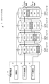
次に、第2の実施形態のレプリケーションからRAID構成への移行過程について図5を用いて説明する。図5は、第2の実施形態のストレージシステムが多重度8のレプリケーションから8フラグメントのRAID構成に移行する過程の一例を示す図である。
Next, the transition process from replication to RAID configuration according to the second embodiment will be described with reference to FIG. FIG. 5 is a diagram illustrating an example of a process in which the storage system according to the second embodiment shifts from replication with
ストレージシステム10は、所定の論理ブロック単位(たとえば、1論理ブロック)でレプリケーションからRAID構成への移行をおこなう。レプリケーションからRAID構成への移行は、多重度8のレプリケーションを初期状態とし、RAID移行状態フェーズ0、RAID移行状態フェーズ1を経て8フラグメントのRAID構成であるRAID移行状態フェーズ2に至る。
The
初期状態において、レプリケーションの多重度は8であり、未だパリティ領域はパリティを保持していない。初期状態のアクセス頻度F(ini)は、あらかじめ定めた閾値S(1)より大きい。初期状態は、アクセス頻度F(ini)が閾値S(1)以下に低下したことを状態遷移条件(F(ini)≦S(1))としてRAID移行状態フェーズ0に遷移する。
In the initial state, the multiplicity of replication is 8, and the parity area still does not hold parity. The access frequency F (ini) in the initial state is larger than a predetermined threshold value S (1). The initial state transitions to the RAID
RAID移行状態フェーズ0において、レプリケーションの多重度は4であり、パリティ領域はパリティを保持する。RAID移行状態フェーズ0のアクセス頻度F(0)は、あらかじめ定めた閾値S(2)より大きい。RAID移行状態フェーズ0は、アクセス頻度F(0)が閾値S(2)以下に低下したことを状態遷移条件(F(0)≦S(2))としてRAID移行状態フェーズ1に遷移する。
In the RAID
RAID移行状態フェーズ1において、レプリケーションの多重度は2であり、パリティ領域はパリティを保持する。RAID移行状態フェーズ1のアクセス頻度F(1)は、あらかじめ定めた閾値S(3)より大きい。RAID移行状態フェーズ1は、アクセス頻度F(1)が閾値S(3)以下に低下したことを状態遷移条件(F(1)≦S(3))としてRAID移行状態フェーズ2に遷移する。
In RAID
RAID移行状態フェーズ2において、レプリケーションの多重度は1であり、パリティ領域はパリティを保持する。すなわち、RAID移行状態フェーズ2は、レプリケーションから8フラグメントのRAID構成に移行した状態である。RAID移行状態フェーズ2のアクセス頻度は、不問でありアクセス頻度の監視がされていない状態である。RAID移行状態フェーズ2は、最終遷移状態である。
In RAID
このように、ストレージシステム10は、レプリケーションの多重度を段階的に低下させてRAIDに移行するため、可用性と容量効率の改善とを両立する。また、ストレージシステム10は、論理ブロックごとにデータ領域に対応するパリティ領域を用意するため、ディスク間のデータ転送を必要としないことからユーザ業務に与える影響を軽減可能である。
In this way, the
なお、アクセス頻度は、所定期間の平均アクセス頻度、最高アクセス頻度などであってもよい。状態遷移のタイミングは、遷移条件成立により速やかにおこなうものであってもよいし、遷移条件成立後の所定の移行タイミング(たとえば、保守時間など)であってもよい。また、遷移条件成立の判定は、所定時間ごとにおこなってもよいし、所定の判定タイミング(たとえば、保守時間など)であってもよい。 The access frequency may be an average access frequency for a predetermined period, a maximum access frequency, or the like. The state transition timing may be promptly performed when the transition condition is satisfied, or may be a predetermined transition timing (for example, maintenance time) after the transition condition is satisfied. In addition, the determination of whether the transition condition is satisfied may be performed every predetermined time, or may be performed at a predetermined determination timing (for example, maintenance time).
次に、第2の実施形態のRAID移行処理について図6を用いて説明する。図6は、第2の実施形態のRAID移行処理のフローチャートを示す図である。
RAID移行処理は、アクセス頻度に応じてレプリケーションの多重度を段階的に低下させてRAIDに移行する処理である。レプリケーションを構成するストレージノード13と接続する計算ノード12のうちマスタとなる計算ノード12がRAID移行処理を実行する。マスタとなる計算ノード12は、定期または不定期の所定のタイミングでRAID移行処理を実行する。マスタとなる計算ノード12は、レプリケーションを構成する論理ブロックの状態が初期状態、RAID移行状態フェーズ0、またはRAID移行状態フェーズ1のときに、その論理ブロックについてRAID移行処理を実行する。なお、マスタとなる計算ノード12は、レプリケーションからRAID構成に移行した後のRAID移行状態フェーズ2をRAID移行処理の対象としない。
Next, RAID migration processing according to the second embodiment will be described with reference to FIG. FIG. 6 is a diagram illustrating a flowchart of RAID migration processing according to the second embodiment.
The RAID migration process is a process for migrating to RAID by gradually reducing the replication multiplicity in accordance with the access frequency. Among the
[ステップS11]計算ノード12(プロセッサ101)は、レプリケーションを構成する論理ブロックのRAID移行状態フェーズ(初期状態、RAID移行状態フェーズ0、またはRAID移行状態フェーズ1)を取得する。
[Step S11] The computing node 12 (processor 101) obtains the RAID migration state phase (initial state, RAID
[ステップS12]計算ノード12は、レプリケーションを構成する論理ブロックのアクセス頻度を評価する。
[ステップS13]計算ノード12は、レプリケーションを構成する論理ブロックのRAID移行状態フェーズとアクセス頻度の評価とを比較し、図5に示した状態遷移条件の成立(フェーズ移行)を判定する。計算ノード12は、状態遷移条件の成立を判定した場合にステップS14にすすみ、状態遷移条件の不成立を判定した場合にRAID移行処理を終了する。
[Step S12] The
[Step S13] The
[ステップS14]計算ノード12は、スレーブノードとなる計算ノード12に対してフェーズ移行処理の実行を指示する。フェーズ移行処理は、レプリケーションの多重度を段階的に低下させる処理である。フェーズ移行処理については、図7を用いて後で説明する。
[Step S14] The
[ステップS15]計算ノード12は、接続するストレージノード13に対してフェーズ移行処理を実行してRAID移行処理を終了する。
このように、計算ノード12は、RAID移行状態フェーズの進行条件の監視をおこなう監視部と、RAID移行状態フェーズの進行(データ領域の選択の是非)を決定する決定部としての機能を含む、RAID移行状態フェーズの進行を管理する管理部としての機能を有する。なお、RAID移行状態フェーズの進行条件は、アクセス頻度に限らず、データ生成からの経過時間、ストレージノードのデータ容量など、任意の条件を設定可能であってもよい。
[Step S15] The
In this way, the
次に、第2の実施形態のフェーズ移行処理について図7を用いて説明する。図7は、第2の実施形態のフェーズ移行処理のフローチャートを示す図である。
フェーズ移行処理は、レプリケーションの多重度を段階的に低下させる処理である。レプリケーションを構成するストレージノード13と接続する計算ノード12がフェーズ移行処理を実行する。レプリケーションを構成するストレージノード13と接続する計算ノード12のうちマスタとなる計算ノード12は、RAID移行処理においてフェーズ移行処理を実行する。レプリケーションを構成するストレージノード13と接続する計算ノード12のうちスレーブノードとなる計算ノード12は、マスタとなる計算ノード12からの実行指示によりフェーズ移行処理を実行する。
Next, phase transition processing according to the second embodiment will be described with reference to FIG. FIG. 7 is a flowchart illustrating the phase transition process according to the second embodiment.
The phase shift process is a process for gradually reducing the multiplicity of replication. The
[ステップS21]計算ノード12(プロセッサ101)は、パリティ生成処理を実行する。パリティ生成処理は、データ領域に対応するパリティを生成する処理である。パリティ生成処理については、図8を用いて後で説明する。 [Step S21] The computation node 12 (processor 101) executes a parity generation process. The parity generation process is a process for generating a parity corresponding to the data area. The parity generation process will be described later with reference to FIG.
[ステップS22]計算ノード12は、レプリケーションの多重度を低下させる場合に次段のRAID移行状態フェーズでデータ領域に保持するデータを選択する。
[ステップS23]計算ノード12は、ステップS22で選択しなかったデータをクリアする。なお、ここでいうクリアは、データの消去の他に、データを保持する物理ブロックと論理ブロックの対応関係のリセットを含む。これにより、ストレージノード13は、データの容量効率の改善を図ることができる。
[Step S22] The
[Step S23] The
[ステップS24]計算ノード12は、データクリアに伴うオフセットの更新をおこない、フェーズ移行処理を終了する。なお、オフセットは、論理アドレスへのアクセスに対する物理アドレスのアクセス先を示す情報である。
[Step S24] The
次に、第2の実施形態のパリティ生成処理について図8を用いて説明する。図8は、第2の実施形態のパリティ生成処理のフローチャートを示す図である。
パリティ生成処理は、データ領域に対応するパリティを生成する処理である。レプリケーションを構成するストレージノード13と接続する計算ノード12がフェーズ移行処理のステップS21でパリティ生成処理を実行する。
Next, parity generation processing according to the second embodiment will be described with reference to FIG. FIG. 8 is a diagram illustrating a flowchart of parity generation processing according to the second embodiment.
The parity generation process is a process for generating a parity corresponding to the data area. The
[ステップS31]計算ノード12(プロセッサ101)は、レプリケーションを構成する論理ブロックのRAID移行状態フェーズがRAID移行状態フェーズ0であるか否かを判定する。計算ノード12は、RAID移行状態フェーズがRAID移行状態フェーズ0である場合にステップS32にすすみ、RAID移行状態フェーズ0でない場合にステップS33にすすむ。
[Step S31] The computing node 12 (processor 101) determines whether or not the RAID migration state phase of the logical block constituting the replication is the RAID
[ステップS32]計算ノード12は、データ領域に保持するデータからパリティを生成してパリティ領域に格納した後、パリティ生成処理を終了する。
[ステップS33]計算ノード12は、パリティ領域に保持するパリティから新しいパリティを生成してパリティ領域に格納した後、パリティ生成処理を終了する。
[Step S32] The
[Step S33] The
このように、計算ノード12は、新規のパリティ、あるいはレプリケーションの多重度低下に伴い更新するパリティを、他の計算ノード12との間でデータの送受信をおこなうことなく生成することができる。したがって、ストレージシステム10は、計算ノード12間のデータ転送を必要としないことからユーザ業務に与える影響を軽減可能である。
As described above, the
次に、第2の実施形態のレプリケーションからRAID構成への移行過程の論理ブロックについて図9から図13を用いて説明する。図9は、第2の実施形態の多重度8のレプリケーションの論理ブロック(パリティなし)の一例を示す図である。
Next, logical blocks in the transition process from replication to RAID configuration according to the second embodiment will be described with reference to FIGS. FIG. 9 is a diagram illustrating an example of a logical block (no parity) of
ND(0)からND(7)のそれぞれは、所定数の論理ブロックについて多重度8のレプリケーションを実現するストレージノード13である。なお、説明を簡潔にするために、ND(0)からND(7)は、1論理ブロックについて多重度8のレプリケーションを実現しているものとして説明する。なお、1論理ブロックの多重度、すなわち、複数のストレージノード13が有する複数のデータ領域にそれぞれ記憶されたデータの多重度は、2のべき乗であることが望ましく、たとえば、2の3乗の8である。
Each of ND (0) to ND (7) is a
このとき、ストレージシステム10は、ストレージノード13をレプリケーション時のデータの多重度に相当する数を有し、たとえば、2のべき乗数である。ストレージシステム10は、多重度8(=2の3乗)のレプリケーションの場合、8つのストレージノード13を含む。
At this time, the
ND(0)からND(7)は、RAID移行状態フェーズが初期状態である。1論理ブロックは、DT(8k)からDT(8k+7)までの8物理ブロックと、PT(8k+8)からPT(8k+11)までの4物理ブロック、合計12物理ブロックから構成される。 From ND (0) to ND (7), the RAID transition state phase is in the initial state. One logical block is composed of 8 physical blocks from DT (8k) to DT (8k + 7) and 4 physical blocks from PT (8k + 8) to PT (8k + 11), for a total of 12 physical blocks.
なお、図9中の物理ブロックのハッチング部は、データを保持していることを示す。ND(0)からND(7)は、それぞれDT(8k)からDT(8k+7)までの8物理ブロックに同一のデータを保持している。パリティ領域は未だパリティを保持しない。 Note that the hatched portion of the physical block in FIG. 9 indicates that data is held. ND (0) to ND (7) hold the same data in 8 physical blocks from DT (8k) to DT (8k + 7), respectively. The parity area does not hold parity yet.
初期状態の論理ブロックは、アクセス頻度の低下により状態遷移条件が成立し、RAID移行状態フェーズ0に移行する。RAID移行状態フェーズ0への移行により、ND(0)からND(7)は、DT(8k)からDT(8k+7)に対応するパリティをPT(8k+8)からPT(8k+11)に生成する。
The logical block in the initial state satisfies the state transition condition due to the decrease in the access frequency, and shifts to the RAID
このときのND(0)からND(7)の様子を図10に示す。図10は、第2の実施形態の多重度8のレプリケーションの論理ブロック(パリティあり)の一例を示す図である。
The state from ND (0) to ND (7) at this time is shown in FIG. FIG. 10 is a diagram illustrating an example of a logical block (with parity) for replication of
ストレージシステム10は、RAID移行状態フェーズ0において初期パリティを生成する。ストレージシステム10は、多重度8(=2の3乗、M=3)であるから、2M-1=22=4エクステント分のデータに対応するパリティを同一のストレージノード13に生成する。たとえば、ND(0)のPT(8k+8)にパリティP(0)を生成して格納し、PT(8k+9)にパリティP(1)を生成して格納し、PT(8k+10)にパリティP(2)を生成して格納し、PT(8k+11)にパリティP(3)を生成して格納する。ND(1)のPT(8k+8)にパリティP(4)を生成して格納し、PT(8k+9)にパリティP(5)を生成して格納し、PT(8k+10)にパリティP(6)を生成して格納し、PT(8k+11)にパリティP(7)を生成して格納する。なお、パリティは、既知の算出式のうちから任意のものを用いることができる。
The
パリティの配置は、以下のように一般化できる。多重度N(=2M)のレプリケーションをNフラグメントのRAID構成に移行する場合のパリティの配置方法を示す。
RAID移行状態フェーズ0におけるアドレスAのエクステントのパリティを(1)式で求められるND(ストレージノード13)に配置する。
The arrangement of parity can be generalized as follows. A parity arrangement method in a case where replication with multiplicity N (= 2 M ) is shifted to a RAID configuration of N fragments will be described.
The parity of the extent of the address A in the RAID
n(A)=A div 2M-1 mod 2M ・・・(1)
これにより、(2)式を満足する2M-1個のエクステントのパリティを1つのNDに配置される。
n (A) = A
As a result, the parity of 2 M−1 extents satisfying the expression (2) is arranged in one ND.
A=α 2M-1 + k0 (0≦k0<2M-1) ・・・(2)
ただし、αは、論理ブロックの位置を示す変数である。
RAID移行状態フェーズ0において、パリティ生成後のND(0)からND(7)は、レプリケーションの多重度を低下させるために、データを保持するデータ領域の選択と、選択しなかったデータ領域のクリアとをおこなう。
A =
Here, α is a variable indicating the position of the logical block.
In RAID
このときのND(0)からND(7)の様子を図11に示す。図11は、第2の実施形態の多重度4のレプリケーションの論理ブロック(パリティあり)の一例を示す図である。
FIG. 11 shows the state from ND (0) to ND (7) at this time. FIG. 11 is a diagram illustrating an example of a logical block (with parity) of
ストレージシステム10は、RAID移行状態フェーズ0においてデータを保持するデータ領域を選択する。図11中の物理ブロックのハッチング部は、選択されたデータ領域を示す。たとえば、ND(0)からND(3)は、偶数アドレスのデータ領域を選択し、ND(4)からND(7)は、奇数アドレスのデータ領域を選択する。これにより、ND(0)からND(7)は、レプリケーションの多重度が4となる。
The
レプリケーションの多重度を低下させる場合のデータ領域の選択は、以下のように一般化できる。多重度N(=2M)のレプリケーションをNフラグメントのRAID構成に移行する場合、計算ノード12は、RAID移行状態フェーズph(ph=0、1、2、・・・、M−1)において(3)式にしたがいデータ領域を選択する。 The selection of the data area when the replication multiplicity is lowered can be generalized as follows. When a replication with multiplicity N (= 2 M ) is migrated to an N-fragment RAID configuration, the computation node 12 (in the RAID migration state phase ph (ph = 0, 1, 2,..., M−1)) ( 3) Select the data area according to the equation.
dn(M−ph−1)=n div 2M-ph-1 mod 2 ・・・(3)
ただし、dn(i)は、ノード番号n(ストレージノード13の識別情報:n=0、1、2、・・・、N−1)の2進数表記の下からi(i=0、1、2、・・・、M−1)番目のビット(桁)の値とする。
d n (M−ph−1) =
However, d n (i) is i (i = 0, 1 from the bottom of the binary number notation of node number n (identification information of storage node 13: n = 0, 1, 2,..., N−1)). ,..., M−1) is the value of the bit (digit).
dn(M−ph−1)=0の場合、計算ノード12は、ND(n)のブロックアドレスが先頭から偶数番目(たとえば、偶数アドレス)のデータ領域を選択し、その余のデータ領域のデータをクリアする。また、dn(M−ph−1)=1の場合、計算ノード12は、ND(n)のブロックアドレスが先頭から奇数番目(たとえば、奇数アドレス)のデータ領域を選択し、その余のデータ領域のデータをクリアする。
When d n (M−ph−1) = 0, the
なお、データ領域の選択と、その余のデータ領域のデータのクリアとにより、それまでアクセス可能だったデータ領域のうちからデータを読み出せないデータ領域が生じるため、計算ノード12は、オフセットの計算式の更新をおこなう。 Note that the selection of the data area and the clearing of the data in the remaining data area result in a data area from which data cannot be read out of the previously accessible data areas. Update the expression.
次に、RAID移行状態フェーズ1のND(0)からND(7)の様子を図12に示す。図12は、第2の実施形態の多重度2のレプリケーションの論理ブロック(パリティあり)の一例を示す図である。
Next, FIG. 12 shows a state from ND (0) to ND (7) in the RAID
RAID移行状態フェーズ1では、計算ノード12は、RAID移行状態フェーズ0で生成した初期パリティから次段のパリティを生成する。計算ノード12は、初期パリティを格納したストレージノード13と同一のストレージノード13に次段のパリティを生成する。したがって、計算ノード12は、初期パリティを格納したストレージノード13に閉じて次段のパリティの生成をおこなう。そのため、ストレージシステム10は、パリティの生成の際に、複数のストレージノード13の間でデータ転送を発生しない。
In the RAID
たとえば、ND(0)のPT(8k+8)に格納するパリティP(10)は、ND(0)のPT(8k+8)に格納していたパリティP(0)と、ND(0)のPT(8k+9)に格納していたパリティP(1)とから生成できる。ND(0)のPT(8k+9)に格納するパリティP(11)は、ND(0)のPT(8k+10)に格納していたパリティP(2)と、ND(0)のPT(8k+11)に格納していたパリティP(3)とから生成できる。同様に、ND(1)のPT(8k+8)に格納するパリティP(12)は、ND(1)のPT(8k+8)に格納していたパリティP(4)と、ND(1)のPT(8k+9)に格納していたパリティP(5)とから生成できる。ND(1)のPT(8k+9)に格納するパリティP(13)は、ND(1)のPT(8k+10)に格納していたパリティP(6)と、ND(1)のPT(8k+11)に格納していたパリティP(7)とから生成できる。 For example, the parity P (10) stored in the PT (8k + 8) of the ND (0) is equal to the parity P (0) stored in the PT (8k + 8) of the ND (0) and the PT (8k + 9) of the ND (0). ) Can be generated from the parity P (1) stored in. Parity P (11) stored in PT (8k + 9) of ND (0) is stored in parity P (2) stored in PT (8k + 10) of ND (0) and PT (8k + 11) of ND (0). It can be generated from the stored parity P (3). Similarly, the parity P (12) stored in the PT (8k + 8) of the ND (1) is equal to the parity P (4) stored in the PT (8k + 8) of the ND (1) and the PT ( 8k + 9) and the parity P (5) stored therein. Parity P (13) stored in PT (8k + 9) of ND (1) is stored in parity P (6) stored in PT (8k + 10) of ND (1) and PT (8k + 11) of ND (1). It can be generated from the stored parity P (7).
なお、計算ノード12は、ND(0)のPT(8k+10)、PT(8k+11)に格納していた初期パリティを、次段のパリティの生成によりクリアする。ND(1)のPT(8k+10)、PT(8k+11)についても同様である。
The
ここで、一般化したRAID移行状態フェーズphのパリティ生成について、以下に説明する。RAID移行状態フェーズphにおいて、(4)式のパリティがすべて同一のストレージノード13に配置されているとすると、RAID移行状態フェーズphのパリティ集合A(ph、kph)は、(5)式および(6)式に分解できる。
Here, the parity generation in the generalized RAID transition state phase ph will be described below. In the RAID transition state phase ph, assuming that all the parities in the equation (4) are arranged in the
A(ph、kph)=α 2M-ph + kph (0≦kph<2M-ph) ・・・(4)
Aeven(ph、kp+1)=α 2M-ph + 2kph+1 (0≦kph+1<2M-ph-1)
・・・(5)
Aodd(ph、kp+1)=α 2M-ph + 2kph+1 + 1(0≦kph+1<2M-ph-1)
・・・(6)
また、A(ph+1、kp+1)のパリティは、Aeven(ph、kp+1)のパリティと、Aodd(ph、kp+1)のパリティとの和である。したがって、計算ノード12は、A(ph、kph)のパリティを保持するストレージノード13に閉じてA(ph+1、kp+1)のパリティを生成することができる。
A (ph, k ph ) =
A even (ph, k p + 1 ) =
... (5)
A odd (ph, k p + 1 ) =
... (6)
The parity of A (ph + 1, k p + 1 ) is the sum of the parity of A even (ph, k p + 1 ) and the parity of A odd (ph, k p + 1 ). Accordingly, the
また、(7)式より、計算ノード12は、RAID移行状態フェーズphが格納するパリティから次段のRAID移行状態フェーズph+1のパリティを生成できる。
A(ph+1、kp+1)=Aeven(ph、kp+1) div 2
=α 2M-(ph+1) + kph+1 (0≦kph+1<2M-(ph+1)) ・・・(7)
したがって、計算ノード12は、RAID移行状態フェーズM−1までのパリティを、1つのストレージノード13が保持する初期パリティから帰納的に生成することができる。
Further, from the equation (7), the
A (ph + 1, k p + 1 ) = A even (ph, k p + 1 )
=
Therefore, the
また、ストレージシステム10は、RAID移行状態フェーズ1においてデータを保持するデータ領域を選択し、その余のデータ領域のデータをクリアする。図12中の物理ブロックのハッチング部は、選択されたデータ領域を示す。たとえば、ND(0)およびND(1)は、下2桁が「00」のアドレスのデータ領域を選択し、ND(2)およびND(3)は、下2桁が「10」のアドレスのデータ領域を選択する。同様に、ND(4)およびND(5)は、下2桁が「01」のアドレスのデータ領域を選択し、ND(6)およびND(7)は、下2桁が「11」のアドレスのデータ領域を選択する。これにより、ND(0)からND(7)は、レプリケーションの多重度が2となる。
Further, the
なお、データ領域の選択と、その余のデータ領域のデータのクリアとにより、それまでアクセス可能だったデータ領域のうちからデータを読み出せないデータ領域が生じるため、計算ノード12は、オフセットの計算式の更新をおこなう。 Note that the selection of the data area and the clearing of the data in the remaining data area result in a data area from which data cannot be read out of the previously accessible data areas. Update the expression.
次に、RAID移行状態フェーズ2のND(0)からND(7)の様子を図13に示す。図13は、第2の実施形態のRAIDに移行した論理ブロックの一例を示す図である。
RAID移行状態フェーズ2では、計算ノード12は、RAID移行状態フェーズ1で生成した前段のパリティから次段のパリティを生成する。計算ノード12は、前段のパリティを格納したストレージノード13と同一のストレージノード13に次段のパリティを生成する。したがって、計算ノード12は、初期パリティを格納したストレージノード13に閉じて次段のパリティの生成をおこなう。そのため、ストレージシステム10は、パリティの生成の際に、複数のストレージノード13の間でデータ転送を発生しない。
Next, FIG. 13 shows a state from ND (0) to ND (7) in the RAID
In the RAID
たとえば、ND(0)のPT(8k+8)に格納するパリティP(20)は、ND(0)のPT(8k+8)に格納していたパリティP(10)と、ND(0)のPT(8k+9)に格納していたパリティP(11)とから生成できる。同様に、ND(1)のPT(8k+8)に格納するパリティP(21)は、ND(1)のPT(8k+8)に格納していたパリティP(12)と、ND(1)のPT(8k+9)に格納していたパリティP(13)とから生成できる。 For example, the parity P (20) stored in the PT (8k + 8) of the ND (0) is equal to the parity P (10) stored in the PT (8k + 8) of the ND (0) and the PT (8k + 9) of the ND (0). ) Can be generated from the parity P (11) stored in. Similarly, the parity P (21) stored in the PT (8k + 8) of the ND (1) is equal to the parity P (12) stored in the PT (8k + 8) of the ND (1) and the PT ( 8k + 9) and the parity P (13) stored in it.
なお、計算ノード12は、ND(0)のPT(8k+9)に格納していた前段のパリティを、次段のパリティの生成によりクリアする。ND(1)のPT(8k+9)についても同様である。
The
また、ストレージシステム10は、RAID移行状態フェーズ2においてデータを保持するデータ領域を選択し、その余のデータ領域のデータをクリアする。図13中の物理ブロックのハッチング部は、選択されたデータ領域を示す。たとえば、ND(0)は、下3桁が「000」のアドレスのデータ領域を選択し、ND(1)は、下3桁が「100」のアドレスのデータ領域を選択する。同様に、ND(2)は、下3桁が「010」のアドレスのデータ領域を選択し、ND(3)は、下3桁が「110」のアドレスのデータ領域を選択する。ND(4)は、下3桁が「001」のアドレスのデータ領域を選択し、ND(5)は、下3桁が「101」のアドレスのデータ領域を選択する。同様に、ND(6)は、下3桁が「011」のアドレスのデータ領域を選択し、ND(7)は、下3桁が「111」のアドレスのデータ領域を選択する。これにより、ND(0)からND(7)は、レプリケーションの多重度が1、すなわちレプリケーションからRAID(たとえば、RAID5)に移行したこととなる。
Further, the
このように、ストレージシステム10は、ストレージノード13ごとに、複数のデータ領域からデータを記憶するデータ領域の半数を複数回選択することにより、データの多重度を低減することができる。
Thus, the
なお、データ領域の選択と、その余のデータ領域のデータのクリアとにより、それまでアクセス可能だったデータ領域のうちからデータを読み出せないデータ領域が生じるため、計算ノード12は、オフセットの計算式の更新をおこなう。 Note that the selection of the data area and the clearing of the data in the remaining data area result in a data area from which data cannot be read out of the previously accessible data areas. Update the expression.
このように、ストレージシステム10は、ストレージノード13間におけるデータ転送なしにパリティを生成し、レプリケーションの多重度を低下させてRAIDへの移行をおこなうことができる。ストレージシステム10は、レプリケーションからRAIDへの移行をおこなう際に、ストレージノード間におけるデータ転送がないことからユーザ業務に与える影響を軽減することができる。また、ストレージシステム10は、生成直後のデータのアクセス頻度が高い状態から低い状態に漸減して移行する過程に応じたレプリケーションとRAIDとをユーザに提供することができる。
In this way, the
[第3の実施形態]
次に、第3の実施形態のストレージシステムについて説明する。第3の実施形態のストレージシステムは、RAID移行状態フェーズにおいて、データ領域の圧縮をおこなう点で第2の実施形態のストレージシステムと異なる。
[Third Embodiment]
Next, a storage system according to the third embodiment will be described. The storage system of the third embodiment differs from the storage system of the second embodiment in that the data area is compressed in the RAID migration state phase.
まず、第3の実施形態のフェーズ移行処理について図14を用いて説明する。図14は、第3の実施形態のフェーズ移行処理のフローチャートを示す図である。
フェーズ移行処理は、レプリケーションの多重度を段階的に低下させる処理である。第3の実施形態のフェーズ移行処理は、データクリアの後、オフセット更新の前に、さらにデータ領域の圧縮をおこなう。
First, phase transition processing according to the third embodiment will be described with reference to FIG. FIG. 14 is a diagram illustrating a flowchart of phase transition processing according to the third embodiment.
The phase shift process is a process for gradually reducing the multiplicity of replication. In the phase transition process of the third embodiment, the data area is further compressed after the data is cleared and before the offset update.
第3の実施形態のフェーズ移行処理の説明では、第2の実施形態のフェーズ移行処理と同様の処理についてステップ番号を同じにして説明を省略する。
[ステップS231]ステップS231は、ステップS23の実行後、ステップS24の実行前に計算ノード12(プロセッサ101)によって実行される。計算ノード12は、ステップS23の実行後の選択されたデータ領域が連続するように、データを移動してデータ領域を圧縮する。
In the description of the phase transition process of the third embodiment, the same step numbers are used for the same processes as the phase transition process of the second embodiment, and the description is omitted.
[Step S231] Step S231 is executed by the computing node 12 (processor 101) after step S23 and before step S24. The
たとえば、データの移動に伴うアドレス変換は、2進数表記の右シフト演算(div 2)により実現することができる。変換後のアドレスは、データ領域のアドレスが偶数の場合にはデータ領域のアドレスの半分にし、データ領域のアドレスが奇数の場合にはデータ領域のアドレスを1だけ下にずらしてから半分にすればよい。 For example, address conversion accompanying data movement can be realized by a binary shift right shift operation (div 2). If the address of the data area is an even number, the converted address should be half of the address of the data area. If the address of the data area is odd, the address of the data area is shifted down by 1 and then halved. Good.
したがって、初期状態におけるデータの物理ブロックのアドレスを(8)式のように表した場合、変換後のアドレスは、(9)式の条件のもとで(10)式のようになる。
A=α2M + Σi=0 M-1da(i)2i ・・・(8)
ただし、αは、論理ブロックの位置を示す変数、da(i)はアドレスAの下からi番目の桁の値である。
Therefore, when the address of the physical block of the data in the initial state is expressed as in equation (8), the converted address is as in equation (10) under the condition of equation (9).
A = α2 M + Σ i = 0 M-1 d a (i) 2 i ··· (8)
Here, α is a variable indicating the position of the logical block, and d a (i) is a value of the i-th digit from the bottom of the address A.
da(ph)=dn(M−ph−1) ・・・(9)
A=α2M-ph-1 + Σi=0 m-ph-2da(i+ph+1)2i ・・・(10)
たとえば、da(ph)=0の物理ブロックは、d0(M−ph−1)=0の場合に選択され、da(ph)=1の物理ブロックは、d0(M−ph−1)=1の場合に選択される。
d a (ph) = d n (M−ph−1) (9)
A = α2 M-ph-1 + Σ i = 0 m-ph-2 d a (i + ph + 1) 2 i ··· (10)
For example, a physical block with d a (ph) = 0 is selected when d 0 (M−ph−1) = 0, and a physical block with d a (ph) = 1 is selected with d 0 (M−ph− 1) Selected when = 1.
したがって、ND(n)において最終的に選択される物理ブロックは、物理ブロックのアドレスの2Mによる剰余がnの2進数表記をビット反転させた整数に一致するものとなる。 Therefore, the physical block that is finally selected in ND (n) matches the integer obtained by bit-reversing the binary representation of n with the 2M remainder of the physical block address.
これより、物理ブロックのアドレスに対してdiv 2Mの演算の実行結果が同一の論理ブロックは、各ノードに一つずつだけ存在する。また、(10)式が示すように、各ノードのデータを保持する物理ブロックは、RAID移行状態フェーズM−1に至ると、いずれのノードも同一アドレスの物理ブロックに変換される。したがって、ストレージシステム10は、RAID移行状態フェーズM−1の圧縮後の物理ブロックでエクステントを構成することができる。これにより、ストレージシステム10は、圧縮後の物理ブロック間でパリティを生成してRAIDを構成できる。
As a result, only one logical block having the same execution result of the
次に、第3の実施形態のレプリケーションからRAID構成への移行過程の論理ブロックについて図15から図19を用いて説明する。図15は、第3の実施形態の多重度4のレプリケーションの圧縮後の論理ブロック(パリティあり)の一例を示す図である。
Next, logical blocks in the transition process from replication to RAID configuration according to the third embodiment will be described with reference to FIGS. FIG. 15 is a diagram illustrating an example of a logical block (with parity) after compression of
なお、図15に示す論理ブロックは、図11に示した多重度4のレプリケーションの論理ブロック(パリティあり)の圧縮後の様子である。
ND(0)からND(7)のそれぞれは、所定数の論理ブロックについて多重度4のレプリケーションを実現するストレージノード13である。
The logical block shown in FIG. 15 is a state after compression of the replication logical block (with parity) of
Each of ND (0) to ND (7) is a
ND(0)からND(7)は、RAID移行状態フェーズ0である。1論理ブロックは、DT(8k)からDT(8k+3)までの4物理ブロックと、PT(8k+4)からPT(8k+7)までの4物理ブロック、合計8物理ブロックから構成される。
ND (0) to ND (7) are in RAID
なお、データ領域の選択、その余のデータ領域のデータのクリア、およびデータ領域の圧縮により、それまでアクセス可能だったデータ領域のうちからデータを読み出せないデータ領域が生じるため、計算ノード12は、オフセットの計算式の更新をおこなう。
Since the selection of the data area, the clearing of the data in the remaining data area, and the compression of the data area result in a data area in which data cannot be read out of the previously accessible data areas, the
次に、RAID移行状態フェーズ1のND(0)からND(7)の様子を図16に示す。図16は、第3の実施形態の多重度2のレプリケーションの圧縮前の論理ブロック(パリティあり)の一例を示す図である。
Next, FIG. 16 shows a state from ND (0) to ND (7) in the RAID
RAID移行状態フェーズ1では、計算ノード12は、RAID移行状態フェーズ0で生成した初期パリティから次段のパリティを生成する。パリティの生成については、第2の実施形態と同様なので説明を省略する。
In the RAID
また、ストレージシステム10は、RAID移行状態フェーズ1においてデータを保持するデータ領域を選択し、その余のデータ領域のデータをクリアする。図16中の物理ブロックのハッチング部は、選択されたデータ領域を示す。たとえば、ND(0)およびND(1)は、下1桁が「0」のアドレスのデータ領域を選択し、ND(2)およびND(3)は、下1桁が「1」のアドレスのデータ領域を選択する。同様に、ND(4)およびND(5)は、下1桁が「0」のアドレスのデータ領域を選択し、ND(6)およびND(7)は、下1桁が「1」のアドレスのデータ領域を選択する。これにより、ND(0)からND(7)は、レプリケーションの多重度が2となる。
Further, the
次に、RAID移行状態フェーズ1のND(0)からND(7)の圧縮後の様子を図17に示す。図17は、第3の実施形態の多重度2のレプリケーションの圧縮後の論理ブロック(パリティあり)の一例を示す図である。
Next, FIG. 17 shows a state after compression from ND (0) to ND (7) in the RAID
1論理ブロックは、DT(8k)とDT(8k+1)の2物理ブロックと、PT(8k+2)とPT(8k+3)の2物理ブロック、合計4物理ブロックから構成される。
なお、データ領域の選択、その余のデータ領域のデータのクリア、およびデータ領域の圧縮により、それまでアクセス可能だったデータ領域のうちからデータを読み出せないデータ領域が生じるため、計算ノード12は、オフセットの計算式の更新をおこなう。
One logical block includes two physical blocks of DT (8k) and DT (8k + 1) and two physical blocks of PT (8k + 2) and PT (8k + 3), for a total of four physical blocks.
Since the selection of the data area, the clearing of the data in the remaining data area, and the compression of the data area result in a data area in which data cannot be read out of the previously accessible data areas, the
次に、RAID移行状態フェーズ2のND(0)からND(7)の様子を図18に示す。図18は、第3の実施形態のRAIDに移行した圧縮前の論理ブロックの一例を示す図である。
Next, FIG. 18 shows a state from ND (0) to ND (7) in RAID
RAID移行状態フェーズ2では、計算ノード12は、RAID移行状態フェーズ1で生成した前段のパリティから次段のパリティを生成する。パリティの生成については、第2の実施形態と同様なので説明を省略する。
In the RAID
また、ストレージシステム10は、RAID移行状態フェーズ2においてデータを保持するデータ領域を選択し、その余のデータ領域のデータをクリアする。図18中の物理ブロックのハッチング部は、選択されたデータ領域を示す。たとえば、ND(0)、ND(2)、ND(4)、およびND(6)は、下1桁が「0」のアドレスのデータ領域を選択する。ND(1)、ND(3)、ND(5)、およびND(7)は、下1桁が「1」のアドレスのデータ領域を選択する。これにより、ND(0)からND(7)は、レプリケーションの多重度が1、すなわちレプリケーションからRAIDに移行したこととなる。
Further, the
次に、RAID移行状態フェーズ2のND(0)からND(7)の圧縮後の様子を図19に示す。図19は、第3の実施形態のRAIDに移行した圧縮後の論理ブロックの一例を示す図である。
Next, FIG. 19 shows a state after compression of ND (0) to ND (7) in RAID
1論理ブロックは、DT(8k)の1物理ブロックと、PT(8k+1)の1物理ブロック、合計2物理ブロックから構成される。これにより、ストレージシステム10は、1論理ブロックについて多重度8のレプリケーションからRAIDへの移行をおこなうことができる。
One logical block is composed of one physical block of DT (8k) and one physical block of PT (8k + 1), for a total of two physical blocks. As a result, the
なお、データ領域の選択、その余のデータ領域のデータのクリア、およびデータ領域の圧縮により、それまでアクセス可能だったデータ領域のうちからデータを読み出せないデータ領域が生じるため、計算ノード12は、オフセットの計算式の更新をおこなう。
Since the selection of the data area, the clearing of the data in the remaining data area, and the compression of the data area result in a data area in which data cannot be read out of the previously accessible data areas, the
このように、ストレージシステム10は、ユーザ業務に与える影響を軽減しながら、レプリケーションからRAIDへと移行することができる。
以上、情報処理装置2、計算ノード12を例示して説明したが、管理ノード11を含むその他の情報処理装置においても適用可能である。
In this way, the
The
なお、上記の処理機能は、コンピュータによって実現することができる。その場合、情報処理装置2、計算ノード12、管理ノード11が有すべき機能の処理内容を記述したプログラムが提供される。そのプログラムをコンピュータで実行することにより、上記処理機能がコンピュータ上で実現される。処理内容を記述したプログラムは、コンピュータで読み取り可能な記録媒体に記録しておくことができる。コンピュータで読み取り可能な記録媒体としては、磁気記憶装置、光ディスク、光磁気記録媒体、半導体メモリなどがある。磁気記憶装置には、ハードディスク装置(HDD)、フレキシブルディスク(FD)、磁気テープなどがある。光ディスクには、DVD、DVD−RAM、CD−ROM/RWなどがある。光磁気記録媒体には、MO(Magneto-Optical disk)などがある。
The above processing functions can be realized by a computer. In that case, a program describing the processing contents of the functions that the
プログラムを流通させる場合には、たとえば、そのプログラムが記録されたDVD、CD−ROMなどの可搬型記録媒体が販売される。また、プログラムをサーバコンピュータの記憶装置に格納しておき、ネットワークを介して、サーバコンピュータから他のコンピュータにそのプログラムを転送することもできる。 When distributing the program, for example, portable recording media such as a DVD and a CD-ROM in which the program is recorded are sold. It is also possible to store the program in a storage device of a server computer and transfer the program from the server computer to another computer via a network.
プログラムを実行するコンピュータは、たとえば、可搬型記録媒体に記録されたプログラムもしくはサーバコンピュータから転送されたプログラムを、自己の記憶装置に格納する。そして、コンピュータは、自己の記憶装置からプログラムを読み取り、プログラムに従った処理を実行する。なお、コンピュータは、可搬型記録媒体から直接プログラムを読み取り、そのプログラムに従った処理を実行することもできる。また、コンピュータは、ネットワークを介して接続されたサーバコンピュータからプログラムが転送されるごとに、逐次、受け取ったプログラムに従った処理を実行することもできる。 The computer that executes the program stores, for example, the program recorded on the portable recording medium or the program transferred from the server computer in its own storage device. Then, the computer reads the program from its own storage device and executes processing according to the program. The computer can also read the program directly from the portable recording medium and execute processing according to the program. In addition, each time a program is transferred from a server computer connected via a network, the computer can sequentially execute processing according to the received program.
また、上記の処理機能の少なくとも一部を、DSP、ASIC、PLDなどの電子回路で実現することもできる。 In addition, at least a part of the processing functions described above can be realized by an electronic circuit such as a DSP, ASIC, or PLD.
1,10 ストレージシステム
2 情報処理装置
3 複製部
4 パリティ生成部
5 データ選択部
6,6b,6c,6d,13 ストレージノード
7 パリティ領域
8 データ領域
11 管理ノード
12 計算ノード
14 ネットワーク
15 ディスク
100 コンピュータ
101 プロセッサ
102 RAM
103 不揮発性メモリ
104 入出力インタフェース
105 通信インタフェース
106 バス
DESCRIPTION OF
103
Claims (10)
前記ストレージノードは、
複数のデータ領域と、前記複数のデータ領域に対応するパリティ領域とを有し、
前記情報処理装置は、
前記複数のストレージノードのうち一のストレージノードが前記複数のデータ領域に記憶する複数のデータをそれぞれ複製し、他のストレージノードが有する前記複数のデータ領域にそれぞれ記憶する複製部と、
前記ストレージノードごとに、前記複数のデータ領域がそれぞれ記憶するデータに対応するパリティを生成してパリティ領域に記憶するパリティ生成部と、
前記複数のストレージノードが有する前記複数のデータ領域にそれぞれ記憶されたデータの多重度が低下するように、前記ストレージノード単体に属する前記複数のデータ領域のうちデータを保持するデータ領域の選択およびその余のデータ領域の解放を、前記複数のストレージノードそれぞれに対して実行するデータ選択部と、
を有することを特徴とするストレージシステム。 In a storage system comprising an information processing device and a plurality of storage nodes,
The storage node is
A plurality of data areas, and a parity area corresponding to the plurality of data areas,
The information processing apparatus includes:
A copying unit in which one of the storage node of the plurality of storage nodes replicates each a plurality of data to be stored in said plurality of data areas, for storing each of the plurality of data areas other storage node has,
For each of the storage node, and parity generating unit to be stored in the parity area and generates a parity corresponding to the data to which the plurality of data areas are respectively stored,
As multiplicity of data stored respectively in said plurality of data areas in which the plurality of storage nodes have decreases, selection and data area for holding data of the plurality of data areas belonging to the storage node itself A data selection unit for releasing the extra data area for each of the plurality of storage nodes ;
A storage system comprising:
2のN乗(Nは2以上の整数)であり、
前記データ選択部は、
前記ストレージノードごとに、前記複数のデータ領域からデータを記憶するデータ領域の半数を複数回選択することで、前記多重度を段階的に低下させることを特徴とする請求項1記載のストレージシステム。 Multiplicity of data stored respectively in said plurality of data areas in which the plurality of storage node has the
2 to the Nth power (N is an integer of 2 or more) ,
The data selection unit
2. The storage system according to claim 1 , wherein the multiplicity is gradually reduced by selecting a half of the data areas for storing data from the plurality of data areas a plurality of times for each storage node.
所定条件に基づいて、前記複数のデータ領域からデータを記憶するデータ領域を選択するか否かを決定する決定部を備え、
前記データ選択部は、
前記決定部が決定した結果に基づいて、前記複数のデータ領域からデータを記憶するデータ領域を選択することを特徴とする請求項2記載のストレージシステム。 The information processing apparatus further includes:
A determination unit for determining whether to select a data area for storing data from the plurality of data areas based on a predetermined condition;
The data selection unit
The storage system according to claim 2, wherein a data area for storing data is selected from the plurality of data areas based on a result determined by the determination unit.
前記ストレージノードを2のべき乗数有し、
前記データ選択部は、
前記ストレージノードに対応する識別情報に基づいて、前記複数のデータ領域からデータを記憶するデータ領域を選択することを特徴とする請求項3記載のストレージシステム。 The storage system
The storage node has a power of 2 ;
The data selection unit
4. The storage system according to claim 3, wherein a data area for storing data is selected from the plurality of data areas based on identification information corresponding to the storage node.
前記その余のデータ領域の解放後、前記ストレージノードごとに、前記データ選択部により選択されたデータ領域に記憶するデータが連続するように再配置することを特徴とする請求項3記載のストレージシステム。 The information processing apparatus includes:
After the release of the the remaining data area, for each of the storage node, according to claim 3, wherein data stored in the data area selected by the data selection unit, characterized in that the re-arranged to continuously Storage system.
前記データ選択部が前記複数のデータ領域からデータを記憶するデータ領域の半数を選択するごとに、選択されたデータ領域に基づいて、パリティを生成することを特徴とする請求項3記載のストレージシステム。 The parity generation unit
4. The storage system according to claim 3, wherein each time the data selection unit selects half of the data areas for storing data from the plurality of data areas , the parity is generated based on the selected data area. .
前記複数のデータ領域にそれぞれ保持されたデータのアクセス頻度とあらかじめ設定した閾値との比較に基づいて、前記複数のデータ領域からデータを記憶するデータ領域を選択するか否かを決定することを特徴とする請求項3記載のストレージシステム。 The determination unit
Characterized by determining whether based on the comparison of the threshold value set in advance as the access frequency of data held respectively in said plurality of data areas, selects a data area for storing data from said plurality of data areas The storage system according to claim 3.
前記複数のストレージノードのうち一のストレージノードが前記複数のデータ領域に記憶する複数のデータをそれぞれ複製し、他のストレージノードが有する前記複数のデータ領域にそれぞれ記憶する複製部と、
前記ストレージノードごとに、前記複数のデータ領域がそれぞれ記憶するデータに対応するパリティを生成してパリティ領域に記憶するパリティ生成部と、
前記複数のストレージノードが有する前記複数のデータ領域にそれぞれ記憶されたデータの多重度が低下するように、前記ストレージノード単体に属する前記複数のデータ領域のうちデータを保持するデータ領域の選択およびその余のデータ領域の解放を、前記複数のストレージノードそれぞれに対して実行するデータ選択部と、
を有することを特徴とする情報処理装置。 In an information processing apparatus connected to a plurality of storage nodes including a plurality of data areas and a parity area corresponding to the plurality of data areas,
A copying unit in which one of the storage node of the plurality of storage nodes replicates each a plurality of data to be stored in said plurality of data areas, for storing each of the plurality of data areas other storage node has,
For each of the storage node, and parity generating unit to be stored in the parity area and generates a parity corresponding to the data to which the plurality of data areas are respectively stored,
As multiplicity of data stored respectively in said plurality of data areas in which the plurality of storage nodes have decreases, selection and data area for holding data of the plurality of data areas belonging to the storage node itself A data selection unit for releasing the extra data area for each of the plurality of storage nodes ;
An information processing apparatus comprising:
前記情報処理装置に、
前記複数のストレージノードのうち一のストレージノードが前記複数のデータ領域に記憶する複数のデータをそれぞれ複製させるとともに、他のストレージノードが有する前記複数のデータ領域にそれぞれ記憶させ、
前記ストレージノードごとに、前記複数のデータ領域がそれぞれ記憶するデータに対応するパリティを生成してパリティ領域に記憶させ、
前記複数のストレージノードが有する前記複数のデータ領域にそれぞれ記憶されたデータの多重度が低下するように、前記ストレージノード単体に属する前記複数のデータ領域のうちデータを保持するデータ領域の選択およびその余のデータ領域の解放を、前記複数のストレージノードそれぞれに対して実行させることを特徴とする情報処理装置の制御プログラム。 In a control program for an information processing apparatus connected to a plurality of storage nodes comprising a plurality of data areas and a parity area corresponding to the plurality of data areas,
In the information processing apparatus,
Together to replicate the respective plurality of data in which one of the storage node is stored in said plurality of data areas among said plurality of storage nodes, are stored respectively in said plurality of data areas other storage node has,
Wherein for each storage node, is stored in the parity area and generates a parity corresponding to the data to which the plurality of data areas are respectively stored,
As multiplicity of data stored respectively in said plurality of data areas in which the plurality of storage nodes have decreases, selection and data area for holding data of the plurality of data areas belonging to the storage node itself the release of the remaining data area, a control program of an information processing apparatus, characterized in that to perform on each of the plurality of storage nodes.
前記情報処理装置が、
前記複数のストレージノードのうち一のストレージノードが前記複数のデータ領域に記憶する複数のデータをそれぞれ複製するとともに、他のストレージノードが有する前記複数のデータ領域にそれぞれ記憶し、
前記ストレージノードごとに、前記複数のデータ領域がそれぞれ記憶するデータに対応するパリティを生成してパリティ領域に記憶し、
前記複数のストレージノードが有する前記複数のデータ領域にそれぞれ記憶されたデータの多重度が低下するように、前記ストレージノード単体に属する前記複数のデータ領域のうちデータを保持するデータ領域の選択およびその余のデータ領域の解放を、前記複数のストレージノードそれぞれに対して実行することを特徴とする情報処理装置の制御方法。
In a control method of an information processing apparatus connected to a plurality of storage nodes including a plurality of data areas and a parity area corresponding to the plurality of data areas,
The information processing apparatus is
With one of the storage nodes of the plurality of storage nodes to replicate a plurality of data to be stored in said plurality of data areas, and stores each of the plurality of data areas other storage node has,
For each of the storage node, and stored in the parity area and generates a parity corresponding to the data to which the plurality of data areas are respectively stored,
As multiplicity of data stored respectively in said plurality of data areas in which the plurality of storage nodes have decreases, selection and data area for holding data of the plurality of data areas belonging to the storage node itself A method for controlling an information processing apparatus , comprising: releasing an extra data area for each of the plurality of storage nodes .
Priority Applications (2)
| Application Number | Priority Date | Filing Date | Title |
|---|---|---|---|
| JP2013069341A JP6171478B2 (en) | 2013-03-28 | 2013-03-28 | Storage system, information processing apparatus, control program for information processing apparatus, and control method for information processing apparatus |
| US14/179,984 US9753803B2 (en) | 2013-03-28 | 2014-02-13 | Storage system and information processing apparatus |
Applications Claiming Priority (1)
| Application Number | Priority Date | Filing Date | Title |
|---|---|---|---|
| JP2013069341A JP6171478B2 (en) | 2013-03-28 | 2013-03-28 | Storage system, information processing apparatus, control program for information processing apparatus, and control method for information processing apparatus |
Publications (2)
| Publication Number | Publication Date |
|---|---|
| JP2014191784A JP2014191784A (en) | 2014-10-06 |
| JP6171478B2 true JP6171478B2 (en) | 2017-08-02 |
Family
ID=51622012
Family Applications (1)
| Application Number | Title | Priority Date | Filing Date |
|---|---|---|---|
| JP2013069341A Expired - Fee Related JP6171478B2 (en) | 2013-03-28 | 2013-03-28 | Storage system, information processing apparatus, control program for information processing apparatus, and control method for information processing apparatus |
Country Status (2)
| Country | Link |
|---|---|
| US (1) | US9753803B2 (en) |
| JP (1) | JP6171478B2 (en) |
Families Citing this family (4)
| Publication number | Priority date | Publication date | Assignee | Title |
|---|---|---|---|---|
| CN105117168A (en) * | 2015-08-17 | 2015-12-02 | 联想(北京)有限公司 | Information processing method and electronic equipment |
| US10592173B2 (en) * | 2018-01-10 | 2020-03-17 | International Business Machines Corporation | Increasing storage efficiency of a data protection technique |
| CN109669636B (en) * | 2018-12-20 | 2020-04-21 | 深圳领络科技有限公司 | Distributed intelligent storage system |
| JP2021099723A (en) | 2019-12-23 | 2021-07-01 | 株式会社日立製作所 | Distributed storage system, data control method and storage medium |
Family Cites Families (11)
| Publication number | Priority date | Publication date | Assignee | Title |
|---|---|---|---|---|
| WO1998012621A1 (en) * | 1996-09-20 | 1998-03-26 | Hitachi, Ltd. | Disk array subsystem |
| JP3616487B2 (en) | 1997-11-21 | 2005-02-02 | アルプス電気株式会社 | Disk array device |
| JP3788961B2 (en) | 2002-08-30 | 2006-06-21 | 株式会社東芝 | Disk array device and method for changing raid level in the same device |
| US7234074B2 (en) * | 2003-12-17 | 2007-06-19 | International Business Machines Corporation | Multiple disk data storage system for reducing power consumption |
| US7305529B1 (en) * | 2003-12-19 | 2007-12-04 | Symantec Corporation | Cooperative data replication |
| US7409512B1 (en) * | 2004-07-01 | 2008-08-05 | Symantec Operating Corporation | Method and apparatus for maintaining information that indicates valid regions of a working volume and using that information to delay volume initialization |
| US7313724B1 (en) * | 2004-07-01 | 2007-12-25 | Symantec Operating Corporation | Method and apparatus for synchronizing redundant data with a volume |
| US8266182B2 (en) * | 2006-06-30 | 2012-09-11 | Harmonic Inc. | Transcoding for a distributed file system |
| US9135115B2 (en) * | 2010-02-27 | 2015-09-15 | Cleversafe, Inc. | Storing data in multiple formats including a dispersed storage format |
| US9158468B2 (en) * | 2013-01-02 | 2015-10-13 | International Business Machines Corporation | High read block clustering at deduplication layer |
| JP6005533B2 (en) * | 2013-01-17 | 2016-10-12 | 株式会社東芝 | Storage device and storage method |
-
2013
- 2013-03-28 JP JP2013069341A patent/JP6171478B2/en not_active Expired - Fee Related
-
2014
- 2014-02-13 US US14/179,984 patent/US9753803B2/en not_active Expired - Fee Related
Also Published As
| Publication number | Publication date |
|---|---|
| US9753803B2 (en) | 2017-09-05 |
| JP2014191784A (en) | 2014-10-06 |
| US20140297973A1 (en) | 2014-10-02 |
Similar Documents
| Publication | Publication Date | Title |
|---|---|---|
| KR102363519B1 (en) | Solid state drive of enhanced multi-stream operations and operation method therof | |
| JP6056453B2 (en) | Program, data management method, and information processing apparatus | |
| JP4620722B2 (en) | Data placement control program, data placement control device, data placement control method, and multi-node storage system | |
| JP4935331B2 (en) | Storage system, storage area selection method and program | |
| JP2008015769A (en) | Storage system and writing distribution method | |
| JP6171478B2 (en) | Storage system, information processing apparatus, control program for information processing apparatus, and control method for information processing apparatus | |
| JP6822274B2 (en) | Information processing systems, methods, and programs | |
| JP2005276196A (en) | System and method for performing drive recovery subsequent to drive failure | |
| CN110058960B (en) | Method, apparatus and computer program product for managing a storage system | |
| JP6209926B2 (en) | Storage control device and storage device control program | |
| JP5949408B2 (en) | Information processing apparatus, information processing apparatus control method, and information processing apparatus control program | |
| JP2014048787A (en) | Information processing apparatus, copy control program and copy control method | |
| US20150293719A1 (en) | Storage Space Processing Method and Apparatus, and Non-Volatile Computer Readable Storage Medium | |
| CN104050200A (en) | Method and device for copying data | |
| JP6069962B2 (en) | Information processing apparatus, area release control program, and area release control method | |
| US9749409B2 (en) | Predictive data replication and acceleration | |
| JP6225731B2 (en) | Storage control device, storage system, and storage control method | |
| JP6582721B2 (en) | Control device, storage system, and control program | |
| JP6011125B2 (en) | Storage device and storage system | |
| US20180307427A1 (en) | Storage control apparatus and storage control method | |
| JP2020177274A (en) | Storage device, storage system, and program | |
| JP2004127275A (en) | Method of managing data storage array and computer system equipped with raid controller | |
| JP6155754B2 (en) | Storage system, distribution device, distribution device control program, and storage system control method | |
| JP6556980B2 (en) | Storage control device, storage control method, and storage control program | |
| JP6524945B2 (en) | Control device, storage device, storage control method and computer program |
Legal Events
| Date | Code | Title | Description |
|---|---|---|---|
| A621 | Written request for application examination |
Free format text: JAPANESE INTERMEDIATE CODE: A621 Effective date: 20151204 |
|
| A977 | Report on retrieval |
Free format text: JAPANESE INTERMEDIATE CODE: A971007 Effective date: 20161028 |
|
| A131 | Notification of reasons for refusal |
Free format text: JAPANESE INTERMEDIATE CODE: A131 Effective date: 20161122 |
|
| A521 | Written amendment |
Free format text: JAPANESE INTERMEDIATE CODE: A523 Effective date: 20170120 |
|
| TRDD | Decision of grant or rejection written | ||
| A01 | Written decision to grant a patent or to grant a registration (utility model) |
Free format text: JAPANESE INTERMEDIATE CODE: A01 Effective date: 20170606 |
|
| A61 | First payment of annual fees (during grant procedure) |
Free format text: JAPANESE INTERMEDIATE CODE: A61 Effective date: 20170619 |
|
| R150 | Certificate of patent or registration of utility model |
Ref document number: 6171478 Country of ref document: JP Free format text: JAPANESE INTERMEDIATE CODE: R150 |
|
| LAPS | Cancellation because of no payment of annual fees |