JP6171103B2 - Wire pair twister and twisted wire manufacturing method - Google Patents
Wire pair twister and twisted wire manufacturing method Download PDFInfo
- Publication number
- JP6171103B2 JP6171103B2 JP2016546650A JP2016546650A JP6171103B2 JP 6171103 B2 JP6171103 B2 JP 6171103B2 JP 2016546650 A JP2016546650 A JP 2016546650A JP 2016546650 A JP2016546650 A JP 2016546650A JP 6171103 B2 JP6171103 B2 JP 6171103B2
- Authority
- JP
- Japan
- Prior art keywords
- rotating body
- twist
- twisted
- electric wire
- electric wires
- Prior art date
- Legal status (The legal status is an assumption and is not a legal conclusion. Google has not performed a legal analysis and makes no representation as to the accuracy of the status listed.)
- Expired - Fee Related
Links
- 241001589086 Bellapiscis medius Species 0.000 title claims description 49
- 238000004519 manufacturing process Methods 0.000 title claims description 24
- 230000007246 mechanism Effects 0.000 claims description 142
- 238000011144 upstream manufacturing Methods 0.000 claims description 14
- 238000004804 winding Methods 0.000 description 17
- 238000010586 diagram Methods 0.000 description 11
- 238000000034 method Methods 0.000 description 6
- 230000002093 peripheral effect Effects 0.000 description 4
- 230000008569 process Effects 0.000 description 4
- 239000004020 conductor Substances 0.000 description 3
- 230000005540 biological transmission Effects 0.000 description 2
- 230000000694 effects Effects 0.000 description 2
- 230000004907 flux Effects 0.000 description 2
- 239000012212 insulator Substances 0.000 description 2
- 238000011084 recovery Methods 0.000 description 2
- 229910000881 Cu alloy Inorganic materials 0.000 description 1
- 238000009434 installation Methods 0.000 description 1
- 238000012986 modification Methods 0.000 description 1
- 230000004048 modification Effects 0.000 description 1
- 238000004904 shortening Methods 0.000 description 1
- 239000013589 supplement Substances 0.000 description 1
Images


Classifications
-
- D—TEXTILES; PAPER
- D07—ROPES; CABLES OTHER THAN ELECTRIC
- D07B—ROPES OR CABLES IN GENERAL
- D07B3/00—General-purpose machines or apparatus for producing twisted ropes or cables from component strands of the same or different material
-
- H—ELECTRICITY
- H01—ELECTRIC ELEMENTS
- H01B—CABLES; CONDUCTORS; INSULATORS; SELECTION OF MATERIALS FOR THEIR CONDUCTIVE, INSULATING OR DIELECTRIC PROPERTIES
- H01B13/00—Apparatus or processes specially adapted for manufacturing conductors or cables
-
- H—ELECTRICITY
- H01—ELECTRIC ELEMENTS
- H01B—CABLES; CONDUCTORS; INSULATORS; SELECTION OF MATERIALS FOR THEIR CONDUCTIVE, INSULATING OR DIELECTRIC PROPERTIES
- H01B13/00—Apparatus or processes specially adapted for manufacturing conductors or cables
- H01B13/02—Stranding-up
Landscapes
- Engineering & Computer Science (AREA)
- Manufacturing & Machinery (AREA)
- Processes Specially Adapted For Manufacturing Cables (AREA)
- Communication Cables (AREA)
- Wire Processing (AREA)
Description
本発明は、ツイスト電線を製造する電線対撚り機と、ツイスト電線の製造方法と、に関する。 The present invention relates to an electric wire twister for manufacturing a twisted electric wire, and a method for manufacturing a twisted electric wire.
従来から、電線を介して伝送される信号が外部から受ける影響(外部磁束によるノイズ)を低減すると共に、その信号が外部へ及ぼす影響(外部への磁束放出)を低減すること等を目的とし、各種のツイスト電線が提案されている。一般に、ツイスト電線は、複数の電線を撚り合わせる機構を備えたツイスト電線製造装置によって製造される。 Conventionally, the purpose is to reduce the influence (noise caused by external magnetic flux) that the signal transmitted through the electric wire receives from the outside, and to reduce the influence that the signal has on the outside (magnetic flux release to the outside), etc. Various twisted electric wires have been proposed. In general, a twisted electric wire is manufactured by a twisted electric wire manufacturing apparatus having a mechanism for twisting a plurality of electric wires.
例えば、図6に示すように、従来のツイスト電線製造装置の一つ(以下「従来装置900」という。)は、2本の電線901を撚り合わせてツイスト電線(ツイストペア線)902を製造するようになっている。従来装置900は、回転体903と、第1捻り送り出し機構904と、第2捻り送り出し機構905と、を備える。図6中の引用符号906の位置はツイスト先端位置を示し、引用符号907の位置はツイスト開始位置を示し、引用符号908はツイスト部分を示し、引用符号909は端子を示す。
For example, as shown in FIG. 6, one of the conventional twisted wire manufacturing apparatuses (hereinafter referred to as “
第1捻り送り出し機構904及び第2捻り送り出し機構905は、矢印Y1に示す向きに電線901を捻りながら、矢印Y2に示す向きに電線901を送出する。回転体903は、送り出し部910及び回転部911を備え、電線901を矢印Y1の向きと同じ矢印Y3の向きに回転させながら矢印Y4の向きに送出する。
The first twist-
回転体903の送り出し部910は、一対の駆動ローラ912を有する。回転部911は、筒状部913、駆動部914、ギア915及び駆動力伝達ギア916を有する。駆動ローラ912は回転体903と共に回転する。
The
第1捻り送り出し機構904は、電線捻り部917及び電線送り出し部918を備える。電線捻り部917は、筒状部919を矢印Y1の向きに回転させる駆動部920、ギア921及び駆動力伝達ギア922を有する。電線送り出し部918は、一対の駆動ローラ923を有する。第2捻り送り出し機構905は、第1捻り送り出し機構904と同様の構成を有する。
The first
従来装置900は、上記構成により、ツイスト電線(ツイスト部分908)のピッチ及び線心間距離の広がりが抑えながら、ツイスト電線(ツイスト部分908)を矢印Y4の向きに送出できるようになっている。
With the above-described configuration, the
従来装置900では、第1捻り送り出し機構904が電線901を捻ると、同機構904の下流側(回転体903に向かう領域)だけでなく、同機構904の上流側(図示しない電線供給機構に向かう領域。以下「電線供給側」という。)においても、電線901が捻られることになる。第2捻り送り出し機構905についても同様である。そこで、従来装置900の電線供給機構(図示省略)は、電線901の捻れ(回転)に対応可能であるように設計される。しかし、そのような設計は、電線供給機構を複雑化させると共に、従来装置900及び電線供給機構を含む設備全体(設備長)を大型化させる一因となる。
In the
本発明は、上記のような事情に鑑みてなされたものであり、その目的は、設備全体を簡素化して設備長の短縮化が可能な電線対撚り機、及び、ツイスト電線の製造方法、を提供することにある。 The present invention has been made in view of the circumstances as described above, and an object of the present invention is to provide a wire-twisting machine that can simplify the entire equipment and shorten the equipment length, and a method of manufacturing a twisted electric wire. It is to provide.
上記した目的を達成するため、本発明に係る電線対撚り機は下記(1)〜(3)の特徴を有し、本発明に係るツイスト電線の製造方法は下記(4)の特徴を有している。
(1)
2本の電線を撚り合わせる回転体であって、該回転体の回転軸及び前記回転軸に垂直に交わるツイスト軸の双方の周りに回転可能な回転体と、
前記回転体に一体的に配置され又は前記回転体の下流側に配置されると共に、撚り合わされた電線を下流側に送り出す第1機構と、
前記回転体の上流側に配置されると共に、前記回転体に供給する前記2本の電線の各々を時計回り及び反時計回りに捻ることが可能な第2機構と、
を備えた電線対撚り機であって、
前記第2機構は、
前記ツイスト軸に直交する第1方向において前記2本の電線を所定の間隔をあけて挟む第1ローラ部及び第2ローラ部と、
前記ツイスト軸及び前記第1方向にそれぞれ直交する第2方向に沿って前記第1ローラ部及び前記第2ローラ部の少なくとも一方をスライドさせるスライド機構と、を有し、
前記スライド機構は、
前記スライドにより、前記第2機構と前記回転体との間において前記2本の電線のそれぞれに時計回り又は反時計回りの捻りを生じさせる、
電線対撚り機であること。
(2)
上記(1)に記載の電線対撚り機において、
前記第1機構が、
前記ツイスト軸を中心にして前記回転体とともに回転する送り出しローラ、又は、撚り合わされた前記2本の電線を巻き取る巻き取りドラムを有する、
電線対撚り機であること。
(3)
上記(1)又は上記(2)に記載の電線対撚り機において、
該電線対撚り機が、
前記回転体、前記第1機構及び前記第2機構の作動を制御し、前記2本の電線を1ピッチずつ撚り合わせると共に送り出す、
電線対撚り機であること。
(4)
所定の回転軸及び前記回転軸に垂直に交わるツイスト軸の双方の周りに回転する回転体と、前記回転体に一体的に配置され又は前記回転体の下流側に配置されると共に撚り合わされた電線を下流側に送り出す第1機構と、前記回転体の上流側に配置されると共に前記回転体に供給する2本の電線の各々を時計回り及び反時計回りに捻ることが可能な第2機構と、を備え、
前記第2機構は、前記ツイスト軸に直交する第1方向において前記2本の電線を所定の間隔をあけて挟む第1ローラ部及び第2ローラ部と、前記ツイスト軸及び前記第1方向にそれぞれ直交する第2方向に沿って前記第1ローラ部及び前記第2ローラ部の少なくとも一方をスライドさせるスライド機構と、を有する、
電線対撚り機を用いたツイスト電線の製造方法であって、
前記スライド機構が、前記スライドにより、前記第2機構と前記回転体との間において前記2本の電線のそれぞれに時計回り又は反時計回りの捻りを生じさせる工程と、
前記回転体及び前記第1機構が、時計回り及び反時計回りの一方の向きに捻られた後に他方の向きに捻られた前記2本の電線を、撚り合わせると共に下流側に送り出す工程と、
を含む、ツイスト電線の製造方法であること。In order to achieve the above object, the wire pair twister according to the present invention has the following features (1) to (3), and the twisted wire manufacturing method according to the present invention has the following feature (4). ing.
(1)
A rotating body for twisting two electric wires, the rotating body being rotatable around both the rotating shaft of the rotating body and a twist shaft perpendicular to the rotating shaft;
A first mechanism arranged integrally with the rotating body or arranged downstream of the rotating body, and sending the twisted electric wire to the downstream side;
A second mechanism arranged upstream of the rotating body and capable of twisting each of the two electric wires supplied to the rotating body clockwise and counterclockwise;
An electric wire twister equipped with
The second mechanism includes
A first roller portion and a second roller portion sandwiching the two electric wires at a predetermined interval in a first direction orthogonal to the twist axis;
A slide mechanism that slides at least one of the first roller portion and the second roller portion along a second direction orthogonal to the twist shaft and the first direction, respectively.
The slide mechanism is
The sliding causes a clockwise or counterclockwise twist in each of the two electric wires between the second mechanism and the rotating body.
Be a wire pair twister.
(2)
In the electric wire twister according to (1) above,
The first mechanism is
A feed roller that rotates with the rotating body around the twist shaft, or a take-up drum that winds the two wires twisted together;
Be a wire pair twister.
(3)
In the electric wire pair twister according to (1) or (2) above,
The wire pair twister is
Controlling the operation of the rotating body, the first mechanism and the second mechanism, and twisting and feeding the two electric wires one pitch at a time;
Be a wire pair twister.
(4)
A rotating body that rotates around both a predetermined rotating shaft and a twist shaft that intersects perpendicularly with the rotating shaft, and an electric wire that is arranged integrally with the rotating body or arranged downstream of the rotating body and twisted together And a second mechanism that is arranged on the upstream side of the rotating body and capable of twisting each of the two electric wires supplied to the rotating body clockwise and counterclockwise. With
The second mechanism includes a first roller portion and a second roller portion that sandwich the two electric wires at a predetermined interval in a first direction orthogonal to the twist axis, and the twist shaft and the first direction, respectively. A slide mechanism that slides at least one of the first roller portion and the second roller portion along a second direction orthogonal to each other.
A method of manufacturing a twisted electric wire using an electric wire twister,
A step of causing the slide mechanism to cause a clockwise or counterclockwise twist in each of the two electric wires between the second mechanism and the rotating body by the slide; and
The rotating body and the first mechanism are twisted in one direction clockwise and counterclockwise and then twisted in the other direction, and twisting and feeding the two wires downstream;
Including a twisted wire manufacturing method.
上記(1)の構成の電線対撚り機によれば、回転体と第1機構と第2機構とを順次に作動させることにより、2本の電線を撚り合わせてツイスト電線を製造できる。具体的には、一例として(図3も参照。)、第2機構がこの第2機構と回転体との間で2本の電線をそれぞれ時計回り(各々の電線の軸線周りに正転する向き)に回転させて捻った後、回転体がツイスト軸周りに回転して2本の電線を撚り合わせる(ツイストさせる)と共に、第2機構が2本の電線をそれぞれ反時計回り(各々の電線の軸線周りに逆転する向き)に回転させて正転する向きの捻り(力)を解除する。そして、第1機構が、撚り合わされた電線を下流側に送り出す。これにより、2本の電線が互いに密着した状態にて撚り合わされ、ツイスト電線が順次に製造される。このように、本構成の電線対撚り機によれば、従来装置のように上流側において2本の電線が回転し続けることがないため、上流側の装置構造を簡素化できる。従って、本構成の電線対撚り機は、設備構造の簡素化を図ることができる。更に、このように設備構造を簡素化できれば、設備長の短縮化もできる。 According to the wire pair twisting machine having the configuration (1), the twisted electric wire can be manufactured by twisting two electric wires by sequentially operating the rotating body, the first mechanism, and the second mechanism. Specifically, as an example (see also FIG. 3), the second mechanism rotates the two electric wires clockwise between the second mechanism and the rotating body (in the direction of normal rotation around the axis of each electric wire). ), And the rotating body rotates around the twist axis to twist the two wires together (twist), and the second mechanism turns the two wires counterclockwise (for each wire). Rotate in the direction of reversing around the axis) and release the twist (force) in the direction of normal rotation. And a 1st mechanism sends out the twisted electric wire downstream. As a result, the two electric wires are twisted together in close contact with each other, and twisted electric wires are sequentially manufactured. Thus, according to the electric wire pair twister of this structure, since two electric wires do not continue rotating on the upstream side like the conventional apparatus, the upstream apparatus structure can be simplified. Therefore, the wire pair twister having this configuration can simplify the equipment structure. Furthermore, if the equipment structure can be simplified in this way, the equipment length can be shortened.
更に、上記(1)の構成の電線対撚り機は、2本の電線の各々に正転する向きの力(捻りのストレス)を加えた後にその力を解除することと、2本の電線の撚り合わせる(ツイストさせる)ことと、を組み合わせることにより、正転する向きに捻られた電線が元の形状に戻ろうとする力(弾性回復力)を利用し、2本の電線同士を強固に密着(自縛)させられる。この電線同士の密着(自縛)により、ツイスト電線は、長期間に亘って撚り合わされた状態を維持できる。このように、本構成の電線対撚り機は、上述した設備構造の簡素化に加え、長期間に亘って撚り合わされた状態を維持可能なツイスト電線を製造できる。 Furthermore, the wire-twisting machine having the configuration (1) described above applies a force (torsional stress) in the direction of normal rotation to each of the two wires, and then releases the force. By combining twisting (twisting) and using the force (elastic recovery force) that the electric wire twisted in the normal rotation direction returns to the original shape, the two electric wires are firmly adhered to each other (Self-binding). Due to the close contact (self-locking) of the electric wires, the twisted electric wires can maintain a twisted state over a long period of time. Thus, the wire pair twister of this structure can manufacture the twisted electric wire which can maintain the state twisted over a long period of time in addition to simplification of the equipment structure mentioned above.
上記(2)の構成の電線対撚り機によれば、第1機構として送り出しローラ又は巻き取りドラムを採用することから、従来装置に比べて簡素な設備により、撚り合わされた電線を下流側に送り出すことができる。よって、本構成の電線対撚り機は、設備装置の簡素化を図ることができる。 According to the wire-twisting machine having the configuration of (2) above, since the feeding roller or the winding drum is adopted as the first mechanism, the twisted electric wires are sent out to the downstream side with simpler equipment than the conventional device. be able to. Therefore, the electric wire pair twister of this structure can aim at simplification of an installation apparatus.
上記(3)の構成の電線対撚り機によれば、1ピッチ分ずつ撚り合わせ及び送り出しを行うため、ピッチ長にばらつきが少ない高品質なツイスト電線を提供できる。 According to the wire-twisting machine having the configuration (3), since twisting and feeding are performed one pitch at a time, a high-quality twisted electric wire with little variation in pitch length can be provided.
上記(4)の構成のツイスト電線の製造方法によれば、上記(1)と同様、設備構造の簡素化、及び、設備長の短縮化を図ることができる。更に、本製造方法によって製造されたツイスト電線は、上記(1)と同様、長期間に亘って撚り合わされた状態を維持できる。 According to the method for manufacturing a twisted electric wire having the configuration (4), the equipment structure can be simplified and the equipment length can be shortened as in the case (1). Furthermore, the twisted electric wire manufactured by this manufacturing method can maintain the state twisted over a long period of time similarly to said (1).
<第1実施形態>
以下、図面を参照しながら、本発明の第1実施形態に係る電線対撚り機(以下「電線対撚り機1」という。)を説明する。図1は、電線対撚り機1を示す模式図である。図2は電線が正転または逆転する様子を示す模式図、図3は2本の電線が撚り合わされる様子を示す模式図である。<First Embodiment>
Hereinafter, an electric wire twister (hereinafter referred to as “electric wire twister 1”) according to a first embodiment of the present invention will be described with reference to the drawings. FIG. 1 is a schematic diagram showing an electric wire pair twisting machine 1. FIG. 2 is a schematic diagram illustrating a state in which the electric wire is rotated forward or reverse, and FIG. 3 is a schematic diagram illustrating a state in which two electric wires are twisted together.
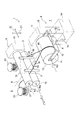
図1に示すように、電線対撚り機1は、従来装置と同様、2本の電線2を撚り合わせて(ツイストさせて)ツイスト電線3(図4を参照。)を製造できるように構成されている。電線対撚り機1は、回転体兼送り出し機構4と、正転逆転捻り機構5と、図示しない制御装置と、を備えている。
As shown in FIG. 1, the wire pair twister 1 is configured so that a twisted wire 3 (see FIG. 4) can be manufactured by twisting (twisting) two
以下、便宜上、回転体兼送り出し機構4を「第1機構」と称呼し、正転逆転捻り機構5を「第2機構」と称呼する。
Hereinafter, for convenience, the rotating body /
なお、図中の引用符号6は電線供給側を示し、引用符号7はツイスト部分送り出し側を示し、引用符号8の中心線は電線供給側6からツイスト部分送り出し側7までを結ぶ軸(以下「ツイスト軸」という。)を示す。電線供給側6が上流側であり、ツイスト部分送り出し側7が下流側である。
In the figure,
先ず、電線対撚り機1の各部材の構成について説明する。 First, the structure of each member of the wire pair twister 1 will be described.
第1機構4は、回転軸部9を有する支柱部10と、一対の回転軸部11を有する支持枠部12と、巻き取りドラム13と、回転体駆動部14と、巻き取りドラム駆動部15と、を含んでいる。
The
支柱部10の回転軸部9は、ツイスト軸8を中心に回転自在な部分として設けられる。回転軸部9には、支持枠部12が固定される。支持枠部12は、巻き取りドラム13を支持する部分であって、その端部に回転軸部11が設けられ、略円柱状の巻き取りドラム13を回転自在に支持している。巻き取りドラム13の胴部は、ツイスト部分16を巻き取る部分として機能する。
The rotating shaft portion 9 of the
回転体駆動部14は、巻き取りドラム13を支持した状態の支持枠部12を例えば矢印R1の向きに回転させられるように構成されている(例えば、図示しないモータ等を含む。)。回転体駆動部14は、図示しない制御装置に制御されて作動する。
The rotating
巻き取りドラム駆動部15は、巻き取りドラム13を矢印R2の向き(ツイスト部分16を巻き取る向き)に回転させられるように構成されている(例えば、図示しないモータ等を含む。)。巻き取りドラム駆動部15は、図示しない制御装置に制御されて作動する。
The take-up
第2機構5は、第1機構4の電線供給側6(上流側)に配置される。第2機構5は、第1ローラ部17及び第2ローラ部18、スライド機構19、並びに、一対の電線ガイド部20を含んでいる。
The
第1ローラ部17及び第2ローラ部18は、2つのドラム23から供給される2本の電線2を所定の間隔をあけた状態にて下流側に送り出し可能(矢印R3及びR4方向に回転可能)であるように構成されている。具体的には、第1ローラ部17及び第2ローラ部18は、2本の電線2が接触する胴部により、ツイスト軸8に直交する第1方向21(上下方向)から2本の電線2を挟み込んでいる。胴部の表面は、電線2と胴部との間に所望の摩擦力が生じるように、ゴム等によって形成されている。第1ローラ部17及び第2ローラ部18のローラ径は、第1機構4の巻き取りドラム13のローラ径よりも小さい。第1ローラ部17及び第2ローラ部18は、2本の電線2を後述するように正転および逆転させるべく、ツイスト軸8及び第1方向21の双方に直交する第2方向22(左右方向)において所定の長さを有するように形成されている。
The
スライド機構19は、下側の第2ローラ部18を第2方向22に沿って移動(スライド)可能であるように構成されている。スライド機構19は、シリンダ等を含んでいる。スライド機構19は、図示しない制御装置に制御されて作動する。なお、スライド機構19は、上記構成に限られず、例えば、第1ローラ部17をスライド可能に構成してもよく、第1ローラ部17及び第2ローラ部18を互いに逆方向にスライド可能に構成してもよい。
The
第1ローラ部17、第2ローラ部18及びスライド機構19により、第2機構5と第1機構4との間において、2本の電線2のそれぞれに対して時計回りの向きの捻り(正転)又は反時計回りの向きの捻り(逆転)を生じさせられる。なお、2本の電線2の正転又は逆転と、電線2の撚り合わせと、の関係については、後述される。
By the
一対の電線ガイド部20は、2本の電線2の間隔を保つために設けられている。一対の電線ガイド部20は、外周面が滑らかな丸棒であり、第1ローラ部17及び第2ローラ部18の近傍に配置されている。
The pair of electric
2本の電線2は、第1ローラ部17及び第2ローラ部18から送出された時点では一対の電線ガイド部20によって定められる間隔だけ離れており、第1機構4に近付くにつれて両者の間隔が徐々に小さくなる(狭まる)ようになっている。2本の電線2は、第1ローラ部17及び第2ローラ部18から第1機構4までの間において、弛まないように適度に張られた状態となっている。
The two
電線供給側6での2本の電線2は、ドラム23から引き出され、第1ローラ部17及び第2ローラ部18により挟み込まれている。電線供給側6での2本の電線2は、後述されるように、従来例のように回転し続けることはない。ドラム23から引き出された状態は、弛んでいてもよい。
The two
次に、図2を参照しながら、第2機構5について説明する。
Next, the
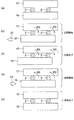
図2(a)は、2本の電線2の初期位置を表している。2本の電線2は、所定の間隔をあけて上側の第1ローラ部17と下側の第2ローラ部18とによって挟まれている。2本の電線2は、外周面の上側が第1ローラ部17に接触し、外周面の下側が第2ローラ部18に接触している。
FIG. 2A shows the initial position of the two
図2(b)に示すように、第2方向22に沿って下側の第2ローラ部18をスライド機構19(図1参照)によってスライドさせると、2本の電線2はそれぞれ正転する向き(矢印R5の向き)に捻られる。
As shown in FIG. 2B, when the lower
図2(c)に示すように、下側の第2ローラ部18が所定距離だけスライドすると、正転の処理が完了する。このとき、2本の電線2には、矢印R5の向きに捻る力(以下「捻りのストレス」とも称呼する。)が及ぼされた状態となっている。なお、上記所定距離とは、2本の電線2をそれぞれ360度以上捻ることができる距離である。
As shown in FIG. 2C, when the lower
図2(d)に示すように、スライド機構19(図1参照)によって図2(b)に示す向きとは逆向きに下側の第2ローラ部18をスライドさせると、2本の電線2はそれぞれ逆転する向き(矢印R6の向き)に捻られる。即ち、捻りが戻される。このとき、上述した捻りのストレスが徐々に解除される。
As shown in FIG. 2D, when the lower
図2(e)において、下側の第2ローラ部18が所定距離(正転時と同じ距離)だけ逆向きにスライドすると、逆転の処理が完了する(捻り戻しが完了する)。このとき、上述した捻りのストレスが完全に解除され、2本の電線2は図2(a)と同じ状態に戻ることになる。
In FIG. 2E, when the lower
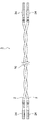
次いで、図3を参照しながら、電線対撚り機1によって2本の電線2が撚り合わされる様子について説明する。なお、図3(a)〜(e)は、電線対撚り機1によって2本の電線2が撚り合わされる様子を、時系列順に並べた図である。
Next, the manner in which the two
図3(a)は、2本の電線2の撚り合わせが始まる前において、第2機構5から第1機構4に向けて延びる2本の電線2の一部を表している(図1も参照。)。なお、本図の上方向が第1機構4(巻き取りドラム13)に向かう方向であり、本図の下方向が第2機構5(第1ローラ部17及び第2ローラ部18)に向かう方向である。
FIG. 3A shows a part of the two
次いで、図3(b)に示すように、第2機構5によって2本の電線2が時計回り(正転する向き。矢印R5の向き)に捻られる。このとき、第1機構4(巻き取りドラム13)と、第2機構5(第1ローラ部17及び第2ローラ部18)と、の間に存在する2本の電線2の全体が、時計回り(正転する向きに)に捻られることになる。例えば、第2機構5による捻りの度合い(電線2の回転角度)は、後述する第1機構4による撚り合わせの度合い(巻き取りドラム13の回転角度)以上であるように、設定し得る。本例では、一例として、電線2の回転角度が360度となるように、第2機構5が2本の電線2を捻るようになっている。
Next, as shown in FIG. 3 (b), the
次いで、図3(c)に示すように、第1機構4によって2本の電線2が時計回り(電線2の捻りの向きと同じ正転する向き。矢印R1の向き)に撚られる(ツイストされる)。その結果、図3(c)に示すように、2本の電線2が撚り合わされる(ツイスト部16を参照。)。但し、このとき、第2機構5は、引き続き電線2の捻りを維持している。換言すると、2本の電線2は、矢印R5の向きに捻られた状態のまま、矢印R1の向きにツイストされる。なお、本例では、一例として、巻き取りドラム13の回転角度が360度(即ち、上述した電線2の回転角度と同じ回転角度)となるように、第1機構4が2本の電線2をツイストさせるようになっている。
Next, as shown in FIG. 3C, the two
次いで、図3(d)に示すように、第2機構5によって2本の電線2が反時計回り(逆転する向き。矢印R6の向き)に捻られる。このとき、上記同様、巻き取りドラム13とローラ部17,18との間に存在する2本の電線2の全体が、反時計回り(逆転する向きに)に捻られることになる。換言すると、このとき、時計回り(正転する向き)の捻りに起因する捻りのストレスが、解除されることになる。
Next, as shown in FIG. 3 (d), the
例えば、第2機構5による反時計回りの捻りの度合い(電線2の回転角度)は、図3(b)に示す時計回りの捻りの度合いと同じであるように、設定し得る。本例では、時計回りの回転角度が360度であるため、反時計回りの回転角度が360度となるように、第2機構5が2本の電線2を捻るようになっている。
For example, the degree of counterclockwise twist by the second mechanism 5 (the rotation angle of the electric wire 2) can be set to be the same as the degree of clockwise twist shown in FIG. In this example, since the clockwise rotation angle is 360 degrees, the
このように捻りのストレスが解除されると、2本の電線2の各々が元の形状(時計回りに捻られる前の形状。図3(a)の形状)に戻ろうとする。換言すると、2本の電線2の各々において、元の形状に戻ろうとする力(弾性回復力)が生じる。この力に起因し、図3(d)のA−A断面図に示すように、2本の電線2が接触している箇所(接触点)においては、2本の電線2のそれぞれが接触したまま逆方向に移動(回転)しようとする。しかし、2本の電線2はそれらの張力等に起因して互いに押し付け合っているため、電線2の外周面(絶縁体)に摩擦力(滑り抵抗)が生じ、回転(滑り)が制限される。
When the twisting stress is released in this manner, each of the two
その結果、第2機構5が電線2を反時計回りに捻り終えても、電線2における捻りのストレスは完全には解消されず、電線2が互いに密着した状態にて捻りのストレスが残存することになる。別の言い方をすると、2本の電線2の一方が他方の回転(滑り)を制限した状態が維持される。即ち、2本の電線2が自縛されることになる。
As a result, even if the
その後、図3(e)に示すように、第1機構4(巻き取りドラム13)により、撚り合わされた電線2(ツイスト部16)が巻き取りドラム13の回転方向(矢印R2の向き)に巻き取られる。 Thereafter, as shown in FIG. 3E, the twisted electric wire 2 (twist portion 16) is wound in the rotation direction of the take-up drum 13 (direction of arrow R2) by the first mechanism 4 (winding drum 13). Taken.
このように、電線対撚り機1は、2本の電線2を互いに密着した状態にて撚り合わせ、ツイスト電線3を製造する。電線対撚り機1によって製造されたツイスト電線3は、2本の電線2が自縛されているため、長期間に亘って撚り合わされた状態を維持できる。
Thus, the wire pair twister 1 twists the two
更に、本例では、図3(a)〜図3(d)に示す一連の処理(1ピッチ分の撚り合わせ)を行う毎に、図3(e)に示す送り出しの処理を行うようになっている。よって、ツイスト部分16が一つ一つ増え、ツイスト電線3が製造されることになる。これにより、電線対撚り機1は、ピッチ長にばらつきが少ない高品質なツイスト電線3を製造できる。
Further, in this example, every time a series of processing (twisting for one pitch) shown in FIGS. 3A to 3D is performed, the feeding processing shown in FIG. 3E is performed. ing. Therefore, the
なお、本例では、図3(c)に示す工程(2本の電線2の撚り合わせ)と、図3(d)に示す工程(捻りのストレスの解除)と、を個別に行っている。しかし、これら2つの工程は、同時に行われても(即ち、2本の電線2を撚り合わせながら捻りのストレスを解除しても)よい。
In this example, the step shown in FIG. 3C (twisting two wires 2) and the step shown in FIG. 3D (releasing twisting stress) are performed individually. However, these two steps may be performed simultaneously (that is, the twisting stress is released while twisting the two
次いで、図4を参照しながら、ツイスト電線3の構造について説明する。
Next, the structure of the twisted
ツイスト電線3は、2本の電線2を撚り合わせるように(ツイストさせるように)束ねた電線であり、各電線の端部には端子24が設けられる。各々の電線2は、導体及び導体を覆う絶縁体から形成されている。導体として、例えば、銅合金線が採用される。ツイスト電線3は、上述した装置の説明からも理解されるように、その全長を任意に設定することが可能である。
The twisted
以上、図1〜図4を参照して説明したように、電線対撚り機1は、巻き取りドラム13(第1機構4の一部)と、第1機構4と、第2機構5と、を順次に作動させることにより、2本の電線2を撚り合わせてツイスト電線3を製造できる。本構成の電線対撚り機によれば、従来装置900のように上流側において2本の電線が回転し続けることがないため、上流側の装置構造を簡素化できる。従って、本構成の電線対撚り機は、設備構造の簡素化を図ることができる。更に、このように設備構造を簡素化できれば、設備長の短縮化もできる。加えて、電線対撚り機1が製造したツイスト電線3は、2本の電線2が自縛されているため、長期間に亘って撚り合わされた状態を維持可能である。
As described above with reference to FIGS. 1 to 4, the wire pair twister 1 includes the winding drum 13 (a part of the first mechanism 4), the
設備長の短縮化に関して説明を補足すると、従来装置900(図6参照)は、第1捻り送り出し機構904及び第2捻り送り出し機構905がそれぞれ電線捻り部917及び電線送り出し部918を備えている。そのため、第1捻り送り出し機構904と第2捻り送り出し機構905とが、所定の間隔をあけて配置される。更に、第1捻り送り出し機構904及び第2捻り送り出し機構905の配置に応じ、回転体903もそれら機構904,905から所定の間隔をあけて配置される。その結果、従来装置900は、設備長が大きくなる。
To supplement the explanation regarding shortening of the equipment length, in the conventional apparatus 900 (see FIG. 6), the first twist-
本発明は、従来装置900の第1捻り送り出し機構904と第2捻り送り出し機構905とに対応する部分(第2機構5)が従来装置900に比べて格段に小さいため、設備長の短縮化を図ることができる。
In the present invention, since the portion corresponding to the first
<第2実施形態>
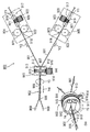
以下、図面を参照しながら、本発明の第2実施形態に係る電線対撚り機(以下「電線対撚り機31」という。)を説明する。電線対撚り機31は、第1実施形態における電線対撚り機1の第1機構4(回転機構と巻取り機構とが一体化)を、回転機構と、巻取り機構と、に分けた実施形態である。図5は、電線対撚り機31を示す模式図である。なお、上述した電線対撚り機1と実質的に同じ部材には同一の符号を付し、詳細な説明を省略する。Second Embodiment
Hereinafter, the wire pair twister (hereinafter referred to as “
図5において、電線対撚り機31は、電線供給側6からツイスト部分送り出し側7までを結ぶツイスト軸8(図1参照)を中心に回転して2本の電線2を撚り合わせる回転体32と、回転体32の上流側に配置される第2機構5と、回転体32の下流側に配置される送り出し機構33と、図示しない制御装置とを、備えている。
In FIG. 5, the
送り出し機構33は、ツイスト軸8(図1参照)を中心にして回転体32とともに回転する一対の送り出しローラ34を有する。回転体32及び送り出し機構33は、上述した電線対撚り機1の第1機構4(図1参照)と基本的に同じ機能を有するように構成されている。
The
電線対撚り機31は、電線対撚り機1に比べ、ツイスト部分16をドラムに巻き取らずに送り出している点で相違するものの、得られる効果は電線対撚り機1と同様である。即ち、電線対撚り機31は、設備構造を簡素化して設備長を短縮化できる。
The wire
ここで、上述した本発明に係るツイスト線製造装置およびツイスト線製造方法の実施形態の特徴を、下記(1)〜(5)に簡潔に纏めて列記する。
(1)
2本の電線(2)を撚り合わせる回転体(巻き取りドラム13)であって、該回転体の回転軸(11)及び前記回転軸に垂直に交わるツイスト軸(8)の双方の周りに回転可能な回転体と、
前記回転体に一体的に配置され(第1実施形態の巻き取りドラム13)又は前記回転体の下流側に配置される(第2実施形態の機構33,34)と共に、撚り合わされた電線を下流側に送り出す第1機構(4)と、
前記回転体(13)の上流側に配置されると共に、前記回転体に供給する前記2本の電線(2)の各々を時計回り及び反時計回りに捻ることが可能な第2機構(5)と、
を備えた電線対撚り機(1,31)であって、
前記第2機構(5)は、
前記ツイスト軸(8)に直交する第1方向(21)において前記2本の電線(2)を所定の間隔をあけて挟む第1ローラ部(17)及び第2ローラ部(18)と、
前記ツイスト軸(8)及び前記第1方向(21)にそれぞれ直交する第2方向(22)に沿って前記第1ローラ部(17)及び前記第2ローラ部(18)の少なくとも一方をスライドさせるスライド機構(19)と、を有し、
前記スライド機構(19)は、
前記スライドにより、前記第2機構(5)と前記回転体(13)との間において前記2本の電線(2)のそれぞれに時計回り又は反時計回りの捻りを生じさせる、
電線対撚り機。
(2)
上記(1)に記載の電線対撚り機において、
前記第1機構(4)が、
前記ツイスト軸(8)を中心にして前記回転体(13)とともに回転する送り出しローラ(34)、又は、撚り合わされた前記2本の電線を巻き取る巻き取りドラム(13)を有する、
電線対撚り機。
(3)
上記(1)又は上記(2)に記載の電線対撚り機において、
該電線対撚り機(1,31)が、
前記回転体(13)、前記第1機構(4)及び前記第2機構(5)の作動を制御し、前記2本の電線を1ピッチずつ撚り合わせると共に送り出す、
電線対撚り機。
(4)
所定の回転軸(11)及び前記回転軸に垂直に交わるツイスト軸(8)の双方の周りに回転する回転体(13)と、前記回転体に一体的に配置され(第1実施形態の回転体13)又は前記回転体の下流側に配置されると共に撚り合わされた電線を下流側に送り出す第1機構(第2実施形態の機構33,34)と、前記回転体の上流側に配置されると共に前記回転体に供給する2本の電線(2)の各々を時計回り及び反時計回りに捻ることが可能な第2機構(5)と、を備え、
前記第2機構(5)は、前記ツイスト軸(8)に直交する第1方向(21)において前記2本の電線を所定の間隔をあけて挟む第1ローラ部(17)及び第2ローラ部(18)と、前記ツイスト軸(8)及び前記第1方向(21)にそれぞれ直交する第2方向(22)に沿って前記第1ローラ部及び前記第2ローラ部の少なくとも一方をスライドさせるスライド機構(19)と、を有する、
電線対撚り機(1,31)を用いたツイスト電線の製造方法であって、
前記スライド機構(19)が、前記スライドにより、前記第2機構(5)と前記回転体(13)との間において前記2本の電線(2)のそれぞれに時計回り又は反時計回りの捻りを生じさせる工程と、
前記回転体(13)及び前記第1機構(4)が、時計回り及び反時計回りの一方の向きに捻られた後に他方の向きに捻られた前記2本の電線(2)を、撚り合わせると共に下流側に送り出す工程と、
を含む、ツイスト電線の製造方法。Here, the features of the embodiments of the twisted wire manufacturing apparatus and the twisted wire manufacturing method according to the present invention described above are briefly summarized in the following (1) to (5).
(1)
A rotating body (winding drum 13) that twists two electric wires (2) and rotates around both the rotating shaft (11) of the rotating body and the twist shaft (8) perpendicular to the rotating shaft. Possible rotating bodies,
The wires twisted together with the rotating body are disposed integrally with the rotating body (winding
A second mechanism (5) which is arranged on the upstream side of the rotating body (13) and can twist each of the two electric wires (2) supplied to the rotating body clockwise and counterclockwise. When,
An electric wire pair twister (1, 31) comprising:
The second mechanism (5)
A first roller portion (17) and a second roller portion (18) that sandwich the two electric wires (2) at a predetermined interval in a first direction (21) perpendicular to the twist axis (8);
Slide at least one of the first roller portion (17) and the second roller portion (18) along a second direction (22) orthogonal to the twist shaft (8) and the first direction (21), respectively. A slide mechanism (19),
The slide mechanism (19)
The sliding causes a clockwise or counterclockwise twist in each of the two electric wires (2) between the second mechanism (5) and the rotating body (13).
Wire pair twister.
(2)
In the electric wire twister according to (1) above,
The first mechanism (4)
A feed roller (34) that rotates with the rotating body (13) around the twist shaft (8), or a take-up drum (13) that winds the two wires twisted together;
Wire pair twister.
(3)
In the electric wire pair twister according to (1) or (2) above,
The wire pair twisting machine (1, 31)
Controlling the operation of the rotating body (13), the first mechanism (4) and the second mechanism (5), twisting and feeding the two electric wires one pitch at a time;
Wire pair twister.
(4)
A rotating body (13) that rotates around both a predetermined rotating shaft (11) and a twist shaft (8) that intersects perpendicularly with the rotating shaft, and a rotating body (13) that is integrally disposed on the rotating body Body 13) or a first mechanism (
The second mechanism (5) includes a first roller portion (17) and a second roller portion that sandwich the two electric wires at a predetermined interval in a first direction (21) orthogonal to the twist shaft (8). (18) and a slide for sliding at least one of the first roller portion and the second roller portion along a second direction (22) orthogonal to the twist shaft (8) and the first direction (21), respectively. A mechanism (19),
A method of manufacturing a twisted electric wire using an electric wire twister (1, 31),
The sliding mechanism (19) causes the two electric wires (2) to twist clockwise or counterclockwise between the second mechanism (5) and the rotating body (13) by the sliding. A process of generating;
The rotating body (13) and the first mechanism (4) twist the two electric wires (2) twisted in one direction clockwise and counterclockwise and then twisted in the other direction. And a process of sending it downstream,
A method of manufacturing a twisted electric wire including:
本発明を詳細にまた特定の実施態様を参照して説明したが、本発明の精神と範囲を逸脱することなく様々な変更や修正を加えることができることは当業者にとって明らかである。 Although the present invention has been described in detail and with reference to specific embodiments, it will be apparent to those skilled in the art that various changes and modifications can be made without departing from the spirit and scope of the invention.
本出願は、2014年9月3日出願の日本特許出願(特願2014−178796)に基づくものであり、その内容はここに参照として取り込まれる。 This application is based on a Japanese patent application filed on September 3, 2014 (Japanese Patent Application No. 2014-17879), the contents of which are incorporated herein by reference.
本発明によれば、従来装置よりも装置の小型化が可能であり、ツイスト電線の目標長さが変更されてもツイスト電線の製造工程の煩雑化を出来る限り防ぐことが可能である。この効果を奏する本発明は、複数の電線が撚り合わされたツイスト電線を製造するための製造装置に関して有用である。 According to the present invention, the apparatus can be made smaller than the conventional apparatus, and even if the target length of the twisted electric wire is changed, the manufacturing process of the twisted electric wire can be prevented as much as possible. The present invention that exhibits this effect is useful for a manufacturing apparatus for manufacturing a twisted electric wire in which a plurality of electric wires are twisted together.
1 電線対撚り機
2 電線
3 ツイスト電線
4 回転体兼送り出し機構(第1機構)
5 正転逆転捻り機構(第2機構)
6 電線供給側
7 ツイスト部分送り出し側
8 ツイスト軸
9 回転軸部
10 支柱部
11 回転軸部
12 支持枠部
13 巻き取りドラム
14 回転体駆動部
15 巻き取りドラム駆動部
16 ツイスト部分
17 第1ローラ部
18 第2ローラ部
19 スライド機構
20 電線ガイド部
21 第1方向
22 第2方向
23 ドラム
24 端子
31 電線対撚り機
32 回転体
33 送り出し機構
34 送り出しローラDESCRIPTION OF SYMBOLS 1 Wire
5 Forward / reverse twist mechanism (second mechanism)
DESCRIPTION OF
Claims (4)
前記回転体に一体的に配置され又は前記回転体の下流側に配置されると共に、撚り合わされた電線を下流側に送り出す第1機構と、
前記回転体の上流側に配置されると共に、前記回転体に供給する前記2本の電線の各々を時計回り及び反時計回りに捻ることが可能な第2機構と、
を備えた電線対撚り機であって、
前記第2機構は、
前記ツイスト軸に直交する第1方向において前記2本の電線を所定の間隔をあけて挟む第1ローラ部及び第2ローラ部と、
前記ツイスト軸及び前記第1方向にそれぞれ直交する第2方向に沿って前記第1ローラ部及び前記第2ローラ部の少なくとも一方をスライドさせるスライド機構と、を有し、
前記スライド機構は、
前記スライドにより、前記第2機構と前記回転体との間において前記2本の電線のそれぞれに時計回り又は反時計回りの捻りを生じさせる、
電線対撚り機。A rotating body for twisting two electric wires, the rotating body being rotatable around both the rotating shaft of the rotating body and a twist shaft perpendicular to the rotating shaft;
A first mechanism arranged integrally with the rotating body or arranged downstream of the rotating body, and sending the twisted electric wire to the downstream side;
A second mechanism arranged upstream of the rotating body and capable of twisting each of the two electric wires supplied to the rotating body clockwise and counterclockwise;
An electric wire twister equipped with
The second mechanism includes
A first roller portion and a second roller portion sandwiching the two electric wires at a predetermined interval in a first direction orthogonal to the twist axis;
A slide mechanism that slides at least one of the first roller portion and the second roller portion along a second direction orthogonal to the twist shaft and the first direction, respectively.
The slide mechanism is
The sliding causes a clockwise or counterclockwise twist in each of the two electric wires between the second mechanism and the rotating body.
Wire pair twister.
前記第1機構が、
前記ツイスト軸を中心にして前記回転体とともに回転する送り出しローラ、又は、撚り合わされた前記2本の電線を巻き取る巻き取りドラムを有する、
電線対撚り機。In the electric wire twister according to claim 1,
The first mechanism is
A feed roller that rotates with the rotating body around the twist shaft, or a take-up drum that winds the two wires twisted together;
Wire pair twister.
該電線対撚り機が、
前記回転体、前記第1機構及び前記第2機構の作動を制御し、前記2本の電線を1ピッチずつ撚り合わせると共に送り出す、
電線対撚り機。In the electric wire pair twisting machine according to claim 1 or claim 2,
The wire pair twister is
Controlling the operation of the rotating body, the first mechanism and the second mechanism, and twisting and feeding the two electric wires one pitch at a time;
Wire pair twister.
前記第2機構は、前記ツイスト軸に直交する第1方向において前記2本の電線を所定の間隔をあけて挟む第1ローラ部及び第2ローラ部と、前記ツイスト軸及び前記第1方向にそれぞれ直交する第2方向に沿って前記第1ローラ部及び前記第2ローラ部の少なくとも一方をスライドさせるスライド機構と、を有する、
電線対撚り機を用いたツイスト電線の製造方法であって、
前記スライド機構が、前記スライドにより、前記第2機構と前記回転体との間において前記2本の電線のそれぞれに時計回り又は反時計回りの捻りを生じさせる工程と、
前記回転体及び前記第1機構が、時計回り及び反時計回りの一方の向きに捻られた後に他方の向きに捻られた前記2本の電線を、撚り合わせると共に下流側に送り出す工程と、
を含む、ツイスト電線の製造方法。A rotating body that rotates around both a predetermined rotating shaft and a twist shaft that intersects perpendicularly with the rotating shaft, and an electric wire that is arranged integrally with the rotating body or arranged downstream of the rotating body and twisted together And a second mechanism that is arranged on the upstream side of the rotating body and capable of twisting each of the two electric wires supplied to the rotating body clockwise and counterclockwise. With
The second mechanism includes a first roller portion and a second roller portion that sandwich the two electric wires at a predetermined interval in a first direction orthogonal to the twist axis, and the twist shaft and the first direction, respectively. A slide mechanism that slides at least one of the first roller portion and the second roller portion along a second direction orthogonal to each other.
A method of manufacturing a twisted electric wire using an electric wire twister,
A step of causing the slide mechanism to cause a clockwise or counterclockwise twist in each of the two electric wires between the second mechanism and the rotating body by the slide; and
The rotating body and the first mechanism are twisted in one direction clockwise and counterclockwise and then twisted in the other direction, and twisting and feeding the two wires downstream;
A method of manufacturing a twisted electric wire including:
Applications Claiming Priority (3)
| Application Number | Priority Date | Filing Date | Title |
|---|---|---|---|
| JP2014178796 | 2014-09-03 | ||
| JP2014178796 | 2014-09-03 | ||
| PCT/JP2015/074793 WO2016035779A1 (en) | 2014-09-03 | 2015-08-31 | Cable pair twisting machine and twisted cable manufacturing method |
Publications (2)
| Publication Number | Publication Date |
|---|---|
| JPWO2016035779A1 JPWO2016035779A1 (en) | 2017-04-27 |
| JP6171103B2 true JP6171103B2 (en) | 2017-07-26 |
Family
ID=55439840
Family Applications (1)
| Application Number | Title | Priority Date | Filing Date |
|---|---|---|---|
| JP2016546650A Expired - Fee Related JP6171103B2 (en) | 2014-09-03 | 2015-08-31 | Wire pair twister and twisted wire manufacturing method |
Country Status (3)
| Country | Link |
|---|---|
| JP (1) | JP6171103B2 (en) |
| CN (1) | CN106663506B (en) |
| WO (1) | WO2016035779A1 (en) |
Cited By (1)
| Publication number | Priority date | Publication date | Assignee | Title |
|---|---|---|---|---|
| WO2021259504A1 (en) * | 2020-06-26 | 2021-12-30 | Komax Holding Ag | Method and device for twisting single cables |
Families Citing this family (7)
| Publication number | Priority date | Publication date | Assignee | Title |
|---|---|---|---|---|
| CN107476100B (en) * | 2017-08-21 | 2023-12-05 | 长治高测新材料科技有限公司 | Manufacturing device for annular steel wire rope |
| CN107758432A (en) * | 2017-09-20 | 2018-03-06 | 郝振 | Metal wire coiler device |
| CN107587366B (en) * | 2017-10-12 | 2020-03-31 | 咸阳宝石钢管钢绳有限公司 | Steel wire rope single-strand twisting machine |
| JP6616380B2 (en) * | 2017-11-06 | 2019-12-04 | 矢崎総業株式会社 | Twisted wire manufacturing apparatus and twisted wire manufacturing method |
| DE102017222107B4 (en) * | 2017-12-07 | 2019-10-31 | Leoni Bordnetz-Systeme Gmbh | Method and device for producing a pipe |
| KR102114395B1 (en) * | 2019-03-27 | 2020-05-22 | 구윤미 | Slim type stranding machine |
| KR102863041B1 (en) * | 2023-10-05 | 2025-09-22 | 리오엠엔씨(주) | Continuous stranding system |
Family Cites Families (5)
| Publication number | Priority date | Publication date | Assignee | Title |
|---|---|---|---|---|
| JPS4739075Y1 (en) * | 1971-08-24 | 1972-11-27 | ||
| JP4859482B2 (en) * | 2006-02-24 | 2012-01-25 | 矢崎総業株式会社 | Twisted wire manufacturing method and manufacturing apparatus |
| JP2009231157A (en) * | 2008-03-25 | 2009-10-08 | Yazaki Corp | Twisted wire and twisted wire manufacturing method |
| JP2012144323A (en) * | 2011-01-11 | 2012-08-02 | Tmt Machinery Inc | Spun yarn winding device and spun yarn winding facility |
| JP5743292B2 (en) * | 2013-06-14 | 2015-07-01 | 栃木住友電工株式会社 | An apparatus for producing an annular concentric twisted cord |
-
2015
- 2015-08-31 CN CN201580047610.XA patent/CN106663506B/en not_active Expired - Fee Related
- 2015-08-31 JP JP2016546650A patent/JP6171103B2/en not_active Expired - Fee Related
- 2015-08-31 WO PCT/JP2015/074793 patent/WO2016035779A1/en not_active Ceased
Cited By (2)
| Publication number | Priority date | Publication date | Assignee | Title |
|---|---|---|---|---|
| WO2021259504A1 (en) * | 2020-06-26 | 2021-12-30 | Komax Holding Ag | Method and device for twisting single cables |
| US12354765B2 (en) | 2020-06-26 | 2025-07-08 | Komax Holding Ag | Method and device for twisting single cables |
Also Published As
| Publication number | Publication date |
|---|---|
| WO2016035779A1 (en) | 2016-03-10 |
| CN106663506A (en) | 2017-05-10 |
| JPWO2016035779A1 (en) | 2017-04-27 |
| CN106663506B (en) | 2018-04-27 |
Similar Documents
| Publication | Publication Date | Title |
|---|---|---|
| JP6171103B2 (en) | Wire pair twister and twisted wire manufacturing method | |
| CN106415739B (en) | Twisted wire manufacture device and twisted wire manufacture method | |
| JP6159481B2 (en) | Twist wire manufacturing apparatus and twist wire manufacturing method | |
| JP4859482B2 (en) | Twisted wire manufacturing method and manufacturing apparatus | |
| US7712697B1 (en) | Core winding apparatus and method of winding a core | |
| JP4981727B2 (en) | Superconducting coil winding method, superconducting coil winding machine and superconducting coil | |
| JP5610276B2 (en) | Ring metal cord manufacturing method and apparatus | |
| JP4375283B2 (en) | Manufacturing method and manufacturing apparatus of extra fine stranded wire | |
| JP6326289B2 (en) | Twist wire manufacturing equipment | |
| JP6259519B2 (en) | Twist wire manufacturing apparatus and twist wire manufacturing method | |
| JP5700344B2 (en) | Ring concentric stranded cord manufacturing equipment | |
| JP5830824B2 (en) | Ring concentric stranded cord manufacturing equipment | |
| JP6678048B2 (en) | Wire twisting device | |
| JP2017024041A (en) | Strand wire manufacturing method and strand wire machine | |
| JP2006144174A (en) | Tubular stranding machine | |
| JP5743292B2 (en) | An apparatus for producing an annular concentric twisted cord | |
| US8887610B2 (en) | Capstan device | |
| JP2007242309A (en) | Twisted wire manufacturing method and manufacturing apparatus | |
| JP2018178319A (en) | Steel cord for rubber article reinforcement, manufacturing method thereof, and buncher twisting wire machine | |
| KR20150071291A (en) | Twisted string device | |
| JP5149843B2 (en) | Linear body feeding method | |
| JPH07238481A (en) | Inner wire and wire twister | |
| JP2003344736A (en) | Method and apparatus for manufacturing tape slot type cable | |
| JPH02241633A (en) | Manufacture of sz stranded wire |
Legal Events
| Date | Code | Title | Description |
|---|---|---|---|
| A621 | Written request for application examination |
Free format text: JAPANESE INTERMEDIATE CODE: A621 Effective date: 20170116 |
|
| TRDD | Decision of grant or rejection written | ||
| A01 | Written decision to grant a patent or to grant a registration (utility model) |
Free format text: JAPANESE INTERMEDIATE CODE: A01 Effective date: 20170606 |
|
| A61 | First payment of annual fees (during grant procedure) |
Free format text: JAPANESE INTERMEDIATE CODE: A61 Effective date: 20170703 |
|
| R150 | Certificate of patent or registration of utility model |
Ref document number: 6171103 Country of ref document: JP Free format text: JAPANESE INTERMEDIATE CODE: R150 |
|
| LAPS | Cancellation because of no payment of annual fees |