JP6170311B2 - Imaging apparatus and control method thereof - Google Patents
Imaging apparatus and control method thereof Download PDFInfo
- Publication number
- JP6170311B2 JP6170311B2 JP2013036205A JP2013036205A JP6170311B2 JP 6170311 B2 JP6170311 B2 JP 6170311B2 JP 2013036205 A JP2013036205 A JP 2013036205A JP 2013036205 A JP2013036205 A JP 2013036205A JP 6170311 B2 JP6170311 B2 JP 6170311B2
- Authority
- JP
- Japan
- Prior art keywords
- imaging
- display
- image data
- period
- time
- Prior art date
- Legal status (The legal status is an assumption and is not a legal conclusion. Google has not performed a legal analysis and makes no representation as to the accuracy of the status listed.)
- Expired - Fee Related
Links
Images


Classifications
-
- H—ELECTRICITY
- H04—ELECTRIC COMMUNICATION TECHNIQUE
- H04N—PICTORIAL COMMUNICATION, e.g. TELEVISION
- H04N23/00—Cameras or camera modules comprising electronic image sensors; Control thereof
- H04N23/60—Control of cameras or camera modules
- H04N23/665—Control of cameras or camera modules involving internal camera communication with the image sensor, e.g. synchronising or multiplexing SSIS control signals
-
- H—ELECTRICITY
- H04—ELECTRIC COMMUNICATION TECHNIQUE
- H04N—PICTORIAL COMMUNICATION, e.g. TELEVISION
- H04N23/00—Cameras or camera modules comprising electronic image sensors; Control thereof
- H04N23/60—Control of cameras or camera modules
- H04N23/63—Control of cameras or camera modules by using electronic viewfinders
Landscapes
- Engineering & Computer Science (AREA)
- Multimedia (AREA)
- Signal Processing (AREA)
- Studio Devices (AREA)
- Indication In Cameras, And Counting Of Exposures (AREA)
Description
本発明は撮像装置及びその制御方法に関し、イメージセンサによって生成される被写体の画像データを表示装置にライブビュー表示する撮像装置及びその制御方法に関するものである。 The present invention relates to an imaging apparatus and a control method therefor, and more particularly to an imaging apparatus that displays live image data of a subject generated by an image sensor on a display apparatus and a control method therefor.
従来、撮像装置としてのデジタルカメラは、CMOSイメージセンサ等のイメージセンサと、LCD(液晶ディスプレイ)等の表示装置を備えている。イメージセンサによって所定のフレームレートで生成される被写体の画像データを、リアルタイムに表示装置に表示させる表示形態(ライブビュー表示)で表示することで、撮影者は表示装置を見ながら撮影を行うことができる。 Conventionally, a digital camera as an imaging apparatus includes an image sensor such as a CMOS image sensor and a display device such as an LCD (liquid crystal display). By displaying the image data of the subject generated at a predetermined frame rate by the image sensor in a display form (live view display) that is displayed on the display device in real time, the photographer can take a picture while looking at the display device. it can.
一般に、表示装置はイメージセンサと非同期で動作しており、イメージセンサによって得られた画像データをメモリに記憶させた後、表示装置の駆動に同期してメモリから画像データを読み出して表示装置へ出力する。この時、イメージセンサによって得られた1フレーム分の画像データが全て書き込まれた後に画像データを読み出すと、イメージセンサで被写体を撮影したタイミングから表示装置に表示されるまでは1フレーム以上の遅延が発生することになる。このために、撮影者が意図した瞬間の静止画が撮れないという問題があった。 In general, the display device operates asynchronously with the image sensor. After the image data obtained by the image sensor is stored in the memory, the image data is read from the memory and output to the display device in synchronization with the drive of the display device. To do. At this time, when the image data is read after all the image data for one frame obtained by the image sensor is written, there is a delay of one frame or more from the timing when the subject is photographed by the image sensor until it is displayed on the display device. Will occur. For this reason, there is a problem that a still image at the moment intended by the photographer cannot be taken.
そこで、上記問題を解決する為に、イメージセンサと画像データを表示装置に表示する表示系とで同期をとる方法が知られている。例えば、特許文献1では、イメージセンサと画像処理回路とフラットパネルディスプレイの処理時間のうち、最も遅い処理時間に合わせるように、相対的に速い処理時間の同期信号にダミーパルスを印加し、処理時間を一致させる方法が開示されている。
In order to solve the above problem, a method is known in which an image sensor and a display system that displays image data on a display device are synchronized. For example, in
また、特許文献2では、イメージセンサから出力された画像信号を記憶手段に書き込み、記憶手段から画像信号を読み出して表示装置に出力するが、その際に次のようにタイミングを制御する方法が開示されている。即ち、記憶手段に対する1フレーム分の書き込みが完了する前に記憶手段から画像信号を読み出して表示装置に出力するように、イメージセンサの駆動タイミングと画像信号読み出しの開始タイミングに所定の位相差を持たせて同期をとる制御である。
Further, in
しかしながら、上述の従来技術では、撮像系と表示系の処理時間の大小関係を考慮していない。 However, the above-described conventional technology does not consider the magnitude relationship between the processing time of the imaging system and the display system.
まず、特許文献1の技術では、フラットパネルディスプレイの処理時間が相対的に早い場合、NTSCなどのVIDEO信号の規格で決まっている同期信号に対してダミーパルスを挿入することになる。そのため、VIDEO信号の規格から外れた信号を出力してしまい、正しい画像が表示されないという問題があった。
First, in the technique of
一方、特許文献2の技術では、記憶手段に対する画像信号の書き込み開始と、画像信号の読み出しの開始に位相差を持たせる方法で同期をとる。更に、画像信号の読み出しの開始タイミングとイメージセンサの駆動の開始タイミングが所定の位相差を持つように同期信号を生成する。しかし、特許文献2に記載された方法では、記憶手段に対する画像信号の書き込みにかかる時間が画像信号の読み出しにかかる時間よりも長い場合、画像信号の書き込みが完了していないにも関わらず、画像信号の読み出しが完了してしまう場合がある。その場合、表示装置へ表示されるのは1フレーム後になり、表示遅延が発生してしまうという問題があった。
On the other hand, in the technique of
本発明は上記問題点を鑑みてなされたものであり、撮像系と表示系の処理時間の大小関係に応じて、イメージセンサが被写体の画像データを生成してから表示されるまでにかかる遅延時間を短縮することを目的とする。 The present invention has been made in view of the above-described problems, and the delay time from the generation of the image sensor to the display of the subject image data is displayed according to the size relationship between the processing times of the imaging system and the display system. It aims at shortening.
上記目的を達成するために、本発明の撮像装置は、受光した光を電気信号に変換する撮像手段と、前記撮像手段を駆動するための同期信号を生成する生成手段と、前記撮像手段から得られた電気信号から画像データを生成する画像処理を行う画像生成手段と、前記画像データを記憶する記憶手段と、表示手段と、前記記憶手段に記憶された画像データを読み出して前記表示手段に表示する表示処理を行う表示制御手段とを有し、前記生成手段は、前記撮像手段の1フレームの周期である第1の周期が前記表示制御手段の1フレームの周期である第2の周期よりも短い場合に、前記表示制御手段による前記表示処理の開始を同期の基準として、前記撮像手段により撮像を開始してから前記表示手段に表示を開始するまでの時間を、前記第1の周期の複数倍の時間から差し引いた時間を、前記同期の基準に加算した時間に、前記第1の周期が開始されるように前記撮像手段の前記同期信号の位相を制御し、前記第1の周期が前記第2の周期以上の場合に、1フレーム分の前記表示処理の完了を同期の基準として、前記撮像手段により撮像を開始してから前記画像生成手段が画像データの生成を開始するまでの時間と、前記画像生成手段における1フレーム分の画像データを生成する処理時間と、前記表示制御手段における1行分の画像データに対して表示処理を行う時間との合計の時間を、前記第1の周期の時間から差し引いた時間を、前記同期の基準に加算した時間に、前記第1の周期が開始されるように前記撮像手段の前記同期信号の位相を制御する。 In order to achieve the above object, an imaging apparatus according to the present invention is obtained from an imaging unit that converts received light into an electrical signal, a generation unit that generates a synchronization signal for driving the imaging unit, and an imaging unit. Image generation means for performing image processing for generating image data from the received electrical signal, storage means for storing the image data, display means, and image data stored in the storage means are read out and displayed on the display means Display control means for performing display processing, wherein the generation means is more than a second period in which a first period that is a period of one frame of the imaging means is a period of one frame of the display control means. If short, as the synchronization of the reference start of the display processing by the display control means, the time from the start of imaging until the start of display on the display means by the image pickup means, said first circumferential The control synchronization signal phase, said first period of time obtained by subtracting from the multiple of the time, the time obtained by adding the synchronization reference, the imaging means such that the first cycle is initiated Is equal to or greater than the second cycle, the completion of the display process for one frame is used as a reference for synchronization until the image generation unit starts generating image data after the imaging unit starts imaging. The total time of the time, the processing time for generating image data for one frame in the image generation means, and the time for performing display processing for the image data for one row in the display control means is the first time. The phase of the synchronization signal of the imaging means is controlled so that the first period is started at a time obtained by adding the time subtracted from the time of the period to the synchronization reference .
本発明によれば、撮像系と表示系の処理時間の大小関係に応じて、イメージセンサが被写体の画像データを生成してから表示されるまでにかかる遅延時間を短縮することができる。 According to the present invention, it is possible to reduce the delay time required from when the image sensor generates image data of a subject to when it is displayed, according to the size relationship between the processing times of the imaging system and the display system.
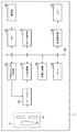
以下、添付図面を参照して本発明を実施するための最良の形態を詳細に説明する。図1は、本発明の実施形態における撮像装置の一例として、デジタルカメラ1の構成を示すブロック図である。本実施形態においては、図1に示す構成のうち、イメージセンサ12、A/D変換部13、画像生成部14、メモリ15は撮像系であり、メモリ15、表示制御部16、LCD17は表示系である。
The best mode for carrying out the present invention will be described below in detail with reference to the accompanying drawings. FIG. 1 is a block diagram illustrating a configuration of a
イメージセンサ12は同期タイミング生成部21によって生成される同期信号によって駆動されて、レンズ10、絞り11を含む撮像光学系2を介して受光した光を電気信号に変換する撮像手段であって、変換した電気信号をA/D変換部13へ出力する。A/D変換部13は、イメージセンサ12から出力されたアナログ信号をデジタル信号へ変換し、画像生成部14へ出力する。画像生成部14は、A/D変換部13によって得られたデジタル信号に対して現像処理を行い、画像データを生成し、メモリ15(記憶手段)に書きこむ(画像処理)。
The
表示制御部16は、CPU20によって生成される同期信号によって駆動され、画像生成部14によって書き込まれた画像データをメモリ15から読み出し、読み出した画像データをLCD17に出力する(表示処理)。LCD17は、表示制御部16から出力されたデータを表示する。なお、イメージセンサ12により周期的に撮影することで得られるフレーム毎の画像データを順次LCD17に表示することで、ライブビュー表示を得ることができる。
The
操作部18は、モードボタンやレリーズボタンによって構成される。操作部18は、ユーザ操作によって選択された撮影モードから特定されるイメージセンサ12の駆動モードや、VIDEO信号の規格であるNTSCやPALの表示方式に基づいた識別信号(以下、「モード信号」と呼ぶ。)をCPU20に出力する。
The
クロック発生部19は、撮像系、表示系で共に用いられるクロック信号を生成する。CPU20及び同期タイミング生成部21は、このクロック信号をもとに同期信号を生成する。
The
CPU20は、各撮影モード及び表示方式に対応する撮像系と表示系の水平・垂直同期信号の周期をテーブルとして保持し、操作部18からのモード信号により撮像系・表示系のフレームレートを決定する。また、表示系の水平・垂直同期信号の周期と、クロック発生部19による表示系のクロックの入力によって表示系同期信号を生成し、表示系同期信号を表示制御部16へ出力する。さらに、撮像系同期信号に同期して生成される、画像生成部14の処理開始のタイミングと画像生成部14から出力されるメモリ15への書き込みの完了割り込みとから、画像生成部14の処理時間を算出し、表示系の処理時間と比較する。なお、詳しい処理時間の算出方法は、処理時間計算部102の説明として後述する。そして比較結果に基づいて、撮像系同期信号が表示系同期信号に対して持つ位相差を求め、比較結果と位相差とを同期タイミング生成部21に出力する。詳細は図2を参照して後述する。
The
同期タイミング生成部21は、クロック発生部19からのクロックをもとに撮像系同期信号を生成する。この時、同期タイミング生成部21は、CPU20から画像生成部14の処理時間と表示系の処理時間とを比較した結果と、撮像系同期信号が表示系同期信号に対して持つ位相差を受け取る。そして、イメージセンサ12と表示系を同期させる基準タイミング(以下、「同期の基準」と呼ぶ。)を決定し、同期の基準に対して位相差を持たせた撮像系同期信号を生成する。なお、同期タイミング生成部21とCPU20の詳細は図2を参照して、また、位相差の算出方法と同期の基準の決定方法に関しては図5を参照して後述する。
The synchronization
バス22には、A/D変換部13、画像生成部14、メモリ15、表示制御部16、クロック発生部19、同期タイミング生成部21が接続されており、CPU20によって制御されるため、相互にデータの授受ができるようになっている。
An A /
図2はCPU20及び同期タイミング生成部21の内部構成を示すブロック図である。CPU20のモード判別部100は、操作部18から出力されたモード信号によって現在のイメージセンサ12の駆動モードとLCD17での表示方式を判別する。そして、判別した結果によって、撮像系及び表示系の水平・垂直同期信号の周期をあらかじめ用意されているテーブルから読み出す。
FIG. 2 is a block diagram showing the internal configuration of the
表示系同期信号生成部101は、モード判別部100から出力された表示系の水平・垂直同期信号の周期をもとに、クロック発生部19から出力された表示系のクロック信号を分周することによって表示系同期信号を生成する。この信号を表示制御部16に出力することにより、表示制御部16は画像データの読み出しを開始する。
The display system synchronization
処理時間計算部102は、モード判別部100から出力された表示系の水平同期信号の周期と、1フレーム内の有効データライン数を乗算することにより、表示制御部16の処理時間(図3に示すTdo)を算出する。この処理時間は1フレーム内の、無効データ期間(ブランキング期間)を含まない。また、撮像系同期信号に同期して生成される、画像生成部14の処理開始のタイミングから、メモリ15への書き込みの完了割り込みがあるまでの時間を画像生成部14の処理時間(図3に示すTio)として算出する。更に、画像生成部14の処理時間を画像生成部14の処理ライン数で割ることにより、1ライン分の処理時間を算出する。
The processing
処理時間比較部103は、処理時間計算部102によって計算した画像生成部14の処理時間Tioと表示制御部16の処理時間Tdoの大小比較をする。位相差設定部104は、処理時間比較部103によって比較した結果に応じて、撮像系同期信号の表示系同期信号に対する位相差を設定する。
The processing
同期タイミング生成部21の同期基準決定部200は、処理時間比較部103によって比較した結果に応じて、同期の基準を設定する。なお、同期の基準を設定する際には、撮像系同期信号生成部201は、クロック発生部19から出力された撮像系のクロック信号を分周することによって撮像系同期信号を生成する。撮像系同期信号を生成する為の情報として、モード判別部100から読み出された撮像系の水平・垂直同期信号の周期と、同期基準決定部200によって決定された同期の基準が入力される。更に、位相差設定部104によって設定された位相差と、表示系同期信号生成部101によって生成される表示系同期信号が入力される。これらの情報に基づいてイメージセンサ12が被写体の画像データを生成してから表示するまでの遅延時間が最短になるように、同期基準決定部200により設定された同期の基準に位相差を持たせた撮像系同期信号を生成し、イメージセンサ12へ出力する。
The synchronization
次に、本発明の実施形態における第1の同期方法を図3のタイミングチャートを用いて説明する。第1の同期方法は、表示系の処理時間が撮像系の処理時間よりも長い場合に実行される同期方法である。撮像系同期信号は、撮像系1フレームTi(第1の周期)の周期でイメージセンサ12に出力される。なお、撮像系の処理時間は、処理時間計算部102で計算した画像生成部14の処理時間Tioである。また、表示系同期信号は、表示系1フレームの時間Tdの周期(第2の周期)でLCD17に出力される。なお、表示系の処理時間は、処理時間計算部102で計算した表示制御部16の処理時間Tdoである。ここでは、TiとTdには2Ti=Tdの関係があるものとして説明する。
Next, a first synchronization method according to the embodiment of the present invention will be described using the timing chart of FIG. The first synchronization method is a synchronization method that is executed when the processing time of the display system is longer than the processing time of the imaging system. The imaging system synchronization signal is output to the
まず、同期の基準を表示系の処理の開始に設定し、その後、同期の基準から位相差を持たせた撮像系同期信号を生成する。位相差の算出方法は次の通りである。まず、撮像系の1周期の開始から画像信号が画像生成部14において処理が開始されるまでの時間Aと、撮像系の1ライン分の処理時間Bとを加算することにより、撮像系同期信号を制御してから表示を開始するまでの時間を算出する。そして、撮像系の2周期2Tiから、先程求めた時間A+Bを引くことで、位相差ΔTを求める。撮像系同期信号生成部201は、求めた位相差ΔTに基づいて撮像系同期信号を生成する。
First, the synchronization reference is set to the start of display system processing, and then an imaging system synchronization signal having a phase difference from the synchronization reference is generated. The calculation method of the phase difference is as follows. First, an imaging system synchronization signal is obtained by adding a time A from the start of one cycle of the imaging system until an image signal is processed in the
このようにして位相差ΔTを求めることで、撮像系の1ライン分の処理が終わったタイミングで表示系の処理を開始することが可能になり、イメージセンサが被写体の画像データを生成してから表示されるまでにかかる遅延時間を短縮することができる。なお、ここでは、撮像系の1ライン分の処理時間Bとしたが、本発明はこれに限るものではなく、遅延時間を短縮することができる予め決められた量の画像データの処理時間としても良い。 By obtaining the phase difference ΔT in this way, it becomes possible to start the processing of the display system at the timing when the processing of one line of the imaging system is completed, and after the image sensor generates the image data of the subject. It is possible to reduce the delay time required for display. Although the processing time B for one line of the imaging system is described here, the present invention is not limited to this, and the processing time for a predetermined amount of image data that can reduce the delay time is also possible. good.
また、ここでは、TiとTdには2Ti=Tdの関係があるものとして説明したが、本発明はこれに限るものではない。Ti<Td(第1の周期が第2の周期よりも短い)の場合に、撮像系の予め決められた量の画像データの処理が終わったタイミングで表示系の処理を開始するように位相差ΔTを求めればよい。なお、この位相差ΔTを求める処理は、モード信号の出力につき1回行ってもよいし、TiとTdとの比が整数比となるフレーム毎(例えば、5Ti=2Tdの場合、5Tiまたは2Td毎)に行ってもよい。 Here, Ti and Td have been described as having a relationship of 2Ti = Td, but the present invention is not limited to this. When Ti <Td (the first period is shorter than the second period), the phase difference is set so that the processing of the display system is started at the timing when the processing of the predetermined amount of image data of the imaging system is completed. What is necessary is just to obtain | require (DELTA) T. The process for obtaining the phase difference ΔT may be performed once for each output of the mode signal, or for each frame in which the ratio of Ti and Td is an integer ratio (for example, when 5Ti = 2Td, every 5Ti or 2Td). ).
次に、本発明の実施形態における第2の同期方法を図4のタイミングチャートを用いて説明する。第2の同期方法は、撮像系の処理時間が表示系の処理時間以上の場合に実行される同期方法である。第1の同期方法と異なり、ここでは、TiとTdにはTi=2Tdの関係があるものとする。なお、信号の種類は第1の同期方法と同じなので、ここでは説明を省略する。 Next, a second synchronization method according to the embodiment of the present invention will be described using the timing chart of FIG. The second synchronization method is a synchronization method that is executed when the processing time of the imaging system is equal to or longer than the processing time of the display system. Unlike the first synchronization method, here, it is assumed that Ti and Td have a relationship of Ti = 2Td. Since the signal type is the same as that in the first synchronization method, the description is omitted here.
まず、同期の基準を表示系の処理の完了に設定し、その後、同期の基準から位相差を持たせた撮像系同期信号を生成する。位相差の算出方法は、撮像系の1周期の開始から映像信号が画像生成部14で処理が開始されるまでの時間Aと、撮像系の処理時間Tioと、表示系の1ライン分の処理時間Cを加算する。これにより、撮像系同期信号を制御してから表示が完了するまでの時間を算出する。そして、撮像系の1周期Tiから、先程求めた時間A+C+Tioを引くことで、位相差ΔTを求める。撮像系同期信号生成部201は、求めた位相差ΔTに基づいて撮像系同期信号を生成する。
First, the synchronization reference is set to the completion of the display system processing, and then an imaging system synchronization signal having a phase difference from the synchronization reference is generated. The phase difference calculation method includes the time A from the start of one cycle of the imaging system until the video signal is processed by the
このようにして位相差ΔTを求めることで、撮像系の1フレーム分の処理が終わったときに、メモリ15に表示されていない1ライン分の画像データが残ることになる。これにより、表示系の処理が撮像系の処理に先んずることを防ぐことができるため、イメージセンサが被写体の画像データを生成してから表示されるまでにかかる遅延時間を短縮することができる。なお、ここでは、表示系の1ライン分の処理時間をCとしたが、本発明はこれに限るものではなく、遅延時間を短縮することができる予め決められた量の画像データの処理時間としても良い。
By obtaining the phase difference ΔT in this way, image data for one line not displayed in the
また、ここでは、TiとTdにはTi=2Tdの関係があるものとして説明したが、本発明はこれに限るものではない。Ti≧Td(第1の周期が第2の周期以上)の場合に、撮像系の1フレーム分の処理が終わったタイミングで予め決められた量の画像データが表示処理されずにメモリ15に残るように位相差ΔTを求めればよい。なお、この位相差ΔTを求める処理は、モード信号の出力につき1回行ってもよいし、TiとTdとの比が整数比となるフレーム数毎(例えば、3Ti=5Tdの場合、3Tiまたは5Td毎)に行ってもよい。
Here, Ti and Td have been described as having a relation of Ti = 2Td, but the present invention is not limited to this. When Ti ≧ Td (the first period is equal to or greater than the second period), a predetermined amount of image data remains in the
図5は、撮影者の操作により、操作部18がモード信号を生成してから、撮像系同期信号生成部201が撮像系同期信号をイメージセンサ12に出力するまでのフローチャートである。この制御は、CPU20と、同期タイミング生成部21によって実行される。
FIG. 5 is a flowchart from when the
S1において、まず、操作部18は、ユーザの操作によって選択された撮影モードから特定されるイメージセンサ12の駆動モードや、VIDEO信号の規格であるNTSCやPALの表示方式に基づいてモード信号を生成し、モード判別部100に出力する。次に、S2において、モード判別部100は、操作部18から出力されたモード信号をもとに、モード判別部100にあらかじめ記録されているテーブルから、撮像系と表示系の水平・垂直同期信号の周期を読み出す。
In S <b> 1, first, the
S3において、表示系同期信号生成部101は、クロック発生部19により生成された表示系のクロックと、モード判別部100から読み出された表示系の水平・垂直同期信号の周期を受け取り、表示系同期信号を生成する。撮像系同期信号生成部201は、クロック発生部19により出力された撮像系のクロックと、モード判別部100から読み出された撮像系の水平・垂直同期信号の周期を受け取り、撮像系同期信号を生成し、イメージセンサ12へ出力する。S4において、画像生成部14と表示制御部16は、撮像系同期信号生成部201と表示系同期信号生成部101によって生成された撮像系同期信号・表示系同期信号をもとに処理を開始する。
In S3, the display system synchronization
S5で、処理時間計算部102は、撮像系同期信号に同期して生成される、画像生成部14の処理開始のタイミングと画像生成部14から出力されたメモリ15への書き込みの完了の割り込みの情報から画像生成部14の処理時間(撮像系の処理時間)を算出する。また、モード判別部100から読み出された表示系の水平同期信号の周期と1フレーム内の有効データライン数を乗算し、表示系の処理時間を算出する。S6において、処理時間比較部103は、処理時間計算部102から撮像系の処理時間と表示系の処理時間を受け取り、撮像系の処理時間が表示系の処理時間よりも短いかどうかを判定する。短い場合はS7に進み、撮像系の処理時間が表示系の処理時間以上の場合はS8に進む。
In S <b> 5, the processing
S7では第1の同期方法により、同期基準決定部200が表示系の処理の開始タイミングを同期の基準として設定する。また、処理時間計算部102は、求めた撮像系の処理時間を全体のライン数で割ることにより撮像系1ライン分の処理時間を算出し、位相差設定部104に出力する。そして、位相差設定部104は図3を参照して上述したように、撮像系の2周期2Tiが開始してから画像生成部14が処理を開始するまでの時間Aと、撮像系1ライン分の処理時間Bを加算し、撮像系の2周期2Tiから引いた時間ΔTを位相差として設定する。
In S7, according to the first synchronization method, the synchronization
一方、S8では第2の同期方法により、同期基準決定部200は表示系の処理の完了タイミングを同期の基準として設定する。そして、位相差設定部104は図4を参照して上述したように、撮像系1周期Tiが開始してから画像生成部14が処理を開始するまでの時間Aと、撮像系の処理時間Tioと、表示系の1ライン分の処理時間Bを加算する。そして、加算した結果を撮像系の1周期Tiから引いた時間ΔTを位相差として設定する。
On the other hand, in S8, according to the second synchronization method, the synchronization
次に、S9において、撮像系同期信号生成部201は、同期基準決定部200により決定した同期の基準に、S7またはS8で位相差設定部104により設定した位相差を適用した撮像系同期信号を生成する。S10では、撮像系同期信号生成部201は、生成した撮像系同期信号をイメージセンサ12へ出力する。
Next, in S9, the imaging system synchronization
S11において、撮影者により終了操作が行われると、操作部18が終了信号を出力し、同期信号の生成を終了する。終了操作が行われない場合にはS5へ戻る。
In S11, when an end operation is performed by the photographer, the
上記の通り本実施形態によれば、撮像系と表示系の処理時間の大小関係を考慮して撮像系同期信号を生成することにより、イメージセンサ12が被写体の画像データを生成してから表示するまでにかかる遅延時間を短縮することができる。 As described above, according to the present embodiment, the imaging system synchronization signal is generated in consideration of the relationship between the processing time of the imaging system and the display system. Can be shortened.
以上、本発明の好ましい実施形態について説明したが、本発明はこれらの実施形態に限定されず、その要旨の範囲内で種々の変形及び変更が可能である。 As mentioned above, although preferable embodiment of this invention was described, this invention is not limited to these embodiment, A various deformation | transformation and change are possible within the range of the summary.
Claims (11)
前記撮像手段を駆動するための同期信号を生成する生成手段と、
前記撮像手段から得られた電気信号から画像データを生成する画像処理を行う画像生成手段と、
前記画像データを記憶する記憶手段と、
表示手段と、
前記記憶手段に記憶された画像データを読み出して前記表示手段に表示する表示処理を行う表示制御手段とを有し、
前記生成手段は、
前記撮像手段の1フレームの周期である第1の周期が前記表示制御手段の1フレームの周期である第2の周期よりも短い場合に、前記表示制御手段による前記表示処理の開始を同期の基準として、前記撮像手段により撮像を開始してから前記表示手段に表示を開始するまでの時間を、前記第1の周期の複数倍の時間から差し引いた時間を、前記同期の基準に加算した時間に、前記第1の周期が開始されるように前記撮像手段の前記同期信号の位相を制御し、
前記第1の周期が前記第2の周期以上の場合に、1フレーム分の前記表示処理の完了を同期の基準として、前記撮像手段により撮像を開始してから前記画像生成手段が画像データの生成を開始するまでの時間と、前記画像生成手段における1フレーム分の画像データを生成する処理時間と、前記表示制御手段における1行分の画像データに対して表示処理を行う時間との合計の時間を、前記第1の周期の時間から差し引いた時間を、前記同期の基準に加算した時間に、前記第1の周期が開始されるように前記撮像手段の前記同期信号の位相を制御する
ことを特徴とする撮像装置。 Imaging means for converting received light into an electrical signal;
Generating means for generating a synchronization signal for driving the imaging means;
Image generating means for performing image processing for generating image data from an electrical signal obtained from the imaging means;
Storage means for storing the image data;
Display means;
Display control means for performing display processing for reading out the image data stored in the storage means and displaying the image data on the display means;
The generating means includes
When the first cycle, which is the cycle of one frame of the imaging unit, is shorter than the second cycle, which is the cycle of one frame of the display control unit, the start of the display process by the display control unit is a reference for synchronization As a time obtained by subtracting the time from the start of imaging by the imaging unit to the start of display on the display unit from the time multiple of the first cycle to the synchronization reference Controlling the phase of the synchronization signal of the imaging means so that the first period is started,
When the first cycle is equal to or greater than the second cycle, the image generation unit generates image data after the imaging unit starts imaging with the completion of the display process for one frame as a reference for synchronization. The total time of the time until the start of image data, the processing time for generating image data for one frame in the image generation means, and the time for performing display processing for image data for one row in the display control means Controlling the phase of the synchronization signal of the imaging means so that the first period is started at a time obtained by adding the time obtained by subtracting the time from the time of the first period to the reference of the synchronization. An imaging device that is characterized.
前記生成手段は、前記操作手段により前記撮影モード及び表示方式の少なくともいずれか一方が変更された場合に、前記位相の制御を行うことを特徴とする請求項1または2に記載の撮像装置。 An operation unit for changing at least one of a shooting mode of the imaging unit and a display method of the display unit;
The imaging apparatus according to claim 1, wherein the generation unit controls the phase when at least one of the shooting mode and the display method is changed by the operation unit.
前記撮像手段の1フレームの周期である第1の周期が前記表示制御手段の1フレームの周期である第2の周期よりも短い場合に、前記生成手段が、前記表示制御手段による前記表示処理の開始を同期の基準として、前記撮像手段により撮像を開始してから前記表示手段に表示を開始するまでの時間を、前記第1の周期の複数倍の時間から差し引いた時間を、前記同期の基準に加算した時間に、前記第1の周期が開始されるように前記撮像手段の前記同期信号の位相を制御する工程と、
前記第1の周期が前記第2の周期以上の場合に、前記生成手段が、1フレーム分の前記表示処理の完了を同期の基準として、前記撮像手段により撮像を開始してから前記画像生成手段が画像データの生成を開始するまでの時間と、前記画像生成手段における1フレーム分の画像データを生成する処理時間と、前記表示制御手段における1行分の画像データに対して表示処理を行う時間との合計の時間を、前記第1の周期の時間から差し引いた時間を、前記同期の基準に加算した時間に、前記第1の周期が開始されるように前記撮像手段の前記同期信号の位相を制御する工程と
を有することを特徴とする撮像装置の制御方法。 An imaging unit that converts received light into an electrical signal, a generation unit that generates a synchronization signal for driving the imaging unit, and an image that performs image processing that generates image data from the electrical signal obtained from the imaging unit Control of an imaging apparatus comprising: generating means; storage means for storing the image data; display means; and display control means for performing display processing for reading out the image data stored in the storage means and displaying the data on the display means. A method,
When the first period, which is the period of one frame of the imaging means, is shorter than the second period, which is the period of one frame of the display control means, the generation means performs the display processing by the display control means. With the start as a reference for synchronization, a time obtained by subtracting the time from the start of image pickup by the image pickup means until the start of display on the display means from the time multiple of the first period is set as the reference for synchronization. Controlling the phase of the synchronization signal of the imaging means so that the first period is started at the time added to
When the first cycle is equal to or greater than the second cycle, the generation unit starts imaging by the imaging unit with the completion of the display process for one frame as a reference for synchronization, and then the image generation unit The time until the start of image data generation, the processing time for generating image data for one frame in the image generation means, and the time for performing display processing for one row of image data in the display control means And the phase of the synchronization signal of the imaging means so that the first period is started at a time obtained by adding the time obtained by subtracting the time of the first period from the time of the first period to the synchronization reference. And a method of controlling the imaging apparatus.
前記撮像手段を駆動するための同期信号を生成する生成手段と、
前記撮像手段から得られた電気信号から画像データを生成する画像処理を行う画像生成手段と、
前記画像データを記憶する記憶手段と、
表示手段と、
前記記憶手段に記憶された画像データを読み出して前記表示手段に表示する表示処理を行う表示制御手段とを有し、
前記生成手段は、
前記撮像手段の1フレームの周期である第1の周期が前記表示制御手段の1フレームの周期である第2の周期よりも短い場合に、前記表示制御手段による前記表示処理の開始を同期の基準として、前記撮像手段により撮像を開始してから前記表示手段に表示を開始するまでの時間を、前記第1の周期の複数倍の時間から差し引いた時間を、前記同期の基準に加算した時間に、前記第1の周期が開始されるように前記撮像手段の前記同期信号の位相を制御し、
予め決められたフレーム数毎に前記同期信号の位相を算出し、前記予め決められたフレーム数の間のフレームでは前記同期信号の位相を算出しない
ことを特徴とする撮像装置。 Imaging means for converting received light into an electrical signal;
Generating means for generating a synchronization signal for driving the imaging means;
Image generating means for performing image processing for generating image data from an electrical signal obtained from the imaging means;
Storage means for storing the image data;
Display means;
Display control means for performing display processing for reading out the image data stored in the storage means and displaying the image data on the display means;
The generating means includes
When the first cycle, which is the cycle of one frame of the imaging unit, is shorter than the second cycle, which is the cycle of one frame of the display control unit, the start of the display process by the display control unit is a reference for synchronization As a time obtained by subtracting the time from the start of imaging by the imaging unit to the start of display on the display unit from the time multiple of the first cycle to the synchronization reference Controlling the phase of the synchronization signal of the imaging means so that the first period is started,
An imaging apparatus, wherein the phase of the synchronization signal is calculated for each predetermined number of frames, and the phase of the synchronization signal is not calculated for frames between the predetermined number of frames.
前記撮像手段を駆動するための同期信号を生成する生成手段と、
前記撮像手段から得られた電気信号から画像データを生成する画像処理を行う画像生成手段と、
前記画像データを記憶する記憶手段と、
表示手段と、
前記記憶手段に記憶された画像データを読み出して前記表示手段に表示する表示処理を行う表示制御手段とを有し、
前記生成手段は、
前記撮像手段の1フレームの周期である第1の周期が前記表示制御手段の1フレームの周期である第2の周期以上の場合に、1フレーム分の前記表示処理の完了を同期の基準として、前記撮像手段により撮像を開始してから前記画像生成手段が画像データの生成を開始するまでの時間と、前記画像生成手段における1フレーム分の画像データを生成する処理時間と、前記表示制御手段における1行分の画像データに対して表示処理を行う時間との合計の時間を、前記第1の周期の時間から差し引いた時間を、前記同期の基準に加算した時間に、前記第1の周期が開始されるように前記撮像手段の前記同期信号の位相を制御し
予め決められたフレーム数毎に前記同期信号の位相を算出し、前記予め決められたフレーム数の間のフレームでは前記同期信号の位相を算出しない
ことを特徴とする撮像装置。 Imaging means for converting received light into an electrical signal;
Generating means for generating a synchronization signal for driving the imaging means;
Image generating means for performing image processing for generating image data from an electrical signal obtained from the imaging means;
Storage means for storing the image data;
Display means;
Display control means for performing display processing for reading out the image data stored in the storage means and displaying the image data on the display means;
The generating means includes
When the first period, which is the period of one frame of the imaging means, is equal to or greater than the second period, which is the period of one frame of the display control means, the completion of the display process for one frame is used as a reference for synchronization. The time from the start of imaging by the imaging unit until the image generation unit starts generating image data, the processing time for generating image data for one frame in the image generation unit, and the display control unit The first period is calculated by adding the time obtained by subtracting the time of the display process for the image data for one line from the time of the first period to the reference for synchronization. wherein calculates a synchronization signal of the phase the synchronization signal phase for each number of frames controlled predetermined of said imaging means to be initiated, said frame between the number of frames that the predetermined Imaging apparatus characterized by not calculate the phase of the period signal.
前記撮像手段の1フレームの周期である第1の周期が前記表示制御手段の1フレームの周期である第2の周期よりも短い場合に、前記表示制御手段による前記表示処理の開始を同期の基準として、前記撮像手段により撮像を開始してから前記表示手段に表示を開始するまでの時間を、前記第1の周期の複数倍の時間から差し引いた時間を、前記同期の基準に加算した時間に、前記第1の周期が開始されるように前記撮像手段の前記同期信号の位相を制御する工程を有し、
予め決められたフレーム数毎に前記同期信号の位相を算出し、前記予め決められたフレーム数の間のフレームでは前記同期信号の位相を算出しないことを特徴とする撮像装置の制御方法。 An imaging unit that converts received light into an electrical signal, a generation unit that generates a synchronization signal for driving the imaging unit, and an image that performs image processing that generates image data from the electrical signal obtained from the imaging unit Control of an imaging apparatus comprising: generating means; storage means for storing the image data; display means; and display control means for performing display processing for reading out the image data stored in the storage means and displaying the data on the display means. A method,
When the first cycle, which is the cycle of one frame of the imaging unit, is shorter than the second cycle, which is the cycle of one frame of the display control unit, the start of the display process by the display control unit is a reference for synchronization As a time obtained by subtracting the time from the start of imaging by the imaging unit to the start of display on the display unit from the time multiple of the first cycle to the synchronization reference And controlling the phase of the synchronization signal of the imaging means so that the first period is started,
A method for controlling an imaging apparatus, wherein the phase of the synchronization signal is calculated for each predetermined number of frames, and the phase of the synchronization signal is not calculated for frames between the predetermined number of frames.
前記撮像手段の1フレームの周期である第1の周期が前記表示制御手段の1フレームの周期である第2の周期以上の場合に、1フレーム分の前記表示処理の完了を同期の基準として、前記撮像手段により撮像を開始してから前記画像生成手段が画像データの生成を開始するまでの時間と、前記画像生成手段における1フレーム分の画像データを生成する処理時間と、前記表示制御手段における1行分の画像データに対して表示処理を行う時間との合計の時間を、前記第1の周期の時間から差し引いた時間を、前記同期の基準に加算した時間に、前記第1の周期が開始されるように前記撮像手段の前記同期信号の位相を制御する工程を有し、
予め決められたフレーム数毎に前記同期信号の位相を算出し、前記予め決められたフレーム数の間のフレームでは前記同期信号の位相を算出しないことを特徴とする撮像装置の制御方法。 An imaging unit that converts received light into an electrical signal, a generation unit that generates a synchronization signal for driving the imaging unit, and an image that performs image processing that generates image data from the electrical signal obtained from the imaging unit Control of an imaging apparatus comprising: generating means; storage means for storing the image data; display means; and display control means for performing display processing for reading out the image data stored in the storage means and displaying the data on the display means. A method,
When the first period, which is the period of one frame of the imaging means, is equal to or greater than the second period, which is the period of one frame of the display control means, the completion of the display process for one frame is used as a reference for synchronization. The time from the start of imaging by the imaging unit until the image generation unit starts generating image data, the processing time for generating image data for one frame in the image generation unit, and the display control unit The first period is calculated by adding the time obtained by subtracting the time of the display process for the image data for one line from the time of the first period to the reference for synchronization. Controlling the phase of the synchronization signal of the imaging means to be started ,
A method for controlling an imaging apparatus, wherein the phase of the synchronization signal is calculated for each predetermined number of frames, and the phase of the synchronization signal is not calculated for frames between the predetermined number of frames.
Priority Applications (2)
| Application Number | Priority Date | Filing Date | Title |
|---|---|---|---|
| JP2013036205A JP6170311B2 (en) | 2013-02-26 | 2013-02-26 | Imaging apparatus and control method thereof |
| US14/177,915 US9225907B2 (en) | 2013-02-26 | 2014-02-11 | Image capturing apparatus and method for controlling the same |
Applications Claiming Priority (1)
| Application Number | Priority Date | Filing Date | Title |
|---|---|---|---|
| JP2013036205A JP6170311B2 (en) | 2013-02-26 | 2013-02-26 | Imaging apparatus and control method thereof |
Publications (3)
| Publication Number | Publication Date |
|---|---|
| JP2014165755A JP2014165755A (en) | 2014-09-08 |
| JP2014165755A5 JP2014165755A5 (en) | 2016-04-07 |
| JP6170311B2 true JP6170311B2 (en) | 2017-07-26 |
Family
ID=51387770
Family Applications (1)
| Application Number | Title | Priority Date | Filing Date |
|---|---|---|---|
| JP2013036205A Expired - Fee Related JP6170311B2 (en) | 2013-02-26 | 2013-02-26 | Imaging apparatus and control method thereof |
Country Status (2)
| Country | Link |
|---|---|
| US (1) | US9225907B2 (en) |
| JP (1) | JP6170311B2 (en) |
Families Citing this family (7)
| Publication number | Priority date | Publication date | Assignee | Title |
|---|---|---|---|---|
| JP6354243B2 (en) * | 2014-03-25 | 2018-07-11 | セイコーエプソン株式会社 | Imaging device, image processing device, display control device, and imaging display device |
| JP6582642B2 (en) * | 2014-08-11 | 2019-10-02 | セイコーエプソン株式会社 | Vehicular imaging device, vehicular imaging display system, and vehicle |
| JP6489802B2 (en) * | 2014-11-13 | 2019-03-27 | キヤノン株式会社 | IMAGING DEVICE, ITS CONTROL METHOD, PROGRAM, AND STORAGE MEDIUM |
| WO2017070588A1 (en) * | 2015-10-23 | 2017-04-27 | Qualcomm Incorporated | Apparatus and methods for synchronizing a controller and sensors |
| JP6620615B2 (en) * | 2016-03-11 | 2019-12-18 | セイコーエプソン株式会社 | Imaging device |
| JP6645279B2 (en) * | 2016-03-11 | 2020-02-14 | セイコーエプソン株式会社 | Imaging equipment |
| JP7242332B2 (en) * | 2019-02-18 | 2023-03-20 | キヤノン株式会社 | SYNCHRONIZATION CONTROL DEVICE, SYNCHRONIZATION CONTROL METHOD, AND PROGRAM |
Family Cites Families (8)
| Publication number | Priority date | Publication date | Assignee | Title |
|---|---|---|---|---|
| JP2006047412A (en) * | 2004-07-30 | 2006-02-16 | Sanyo Electric Co Ltd | Interface device and synchronizing method |
| JP4331087B2 (en) * | 2004-10-28 | 2009-09-16 | 富士フイルム株式会社 | Imaging apparatus and control method thereof |
| JP4727457B2 (en) * | 2006-03-08 | 2011-07-20 | 富士フイルム株式会社 | Imaging device |
| JP4912141B2 (en) * | 2006-12-26 | 2012-04-11 | キヤノン株式会社 | Imaging display device, imaging display control method and system |
| JP2007323662A (en) * | 2007-07-09 | 2007-12-13 | Canon Inc | Data transfer method |
| JP5499831B2 (en) | 2010-03-30 | 2014-05-21 | セイコーエプソン株式会社 | Digital camera |
| JP2011254416A (en) * | 2010-06-04 | 2011-12-15 | Seiko Epson Corp | Photographing device |
| JP5767037B2 (en) * | 2011-06-20 | 2015-08-19 | オリンパス株式会社 | Electronic endoscope device |
-
2013
- 2013-02-26 JP JP2013036205A patent/JP6170311B2/en not_active Expired - Fee Related
-
2014
- 2014-02-11 US US14/177,915 patent/US9225907B2/en not_active Expired - Fee Related
Also Published As
| Publication number | Publication date |
|---|---|
| US20140240542A1 (en) | 2014-08-28 |
| JP2014165755A (en) | 2014-09-08 |
| US9225907B2 (en) | 2015-12-29 |
Similar Documents
| Publication | Publication Date | Title |
|---|---|---|
| JP6170311B2 (en) | Imaging apparatus and control method thereof | |
| JP4917345B2 (en) | Sync signal generating apparatus, digital camera, and sync signal generating method | |
| US10104296B2 (en) | Image-displaying device and display control circuit | |
| US10187576B2 (en) | Image-displaying device and image data generation device | |
| TWI513321B (en) | An image processing apparatus, an information processing apparatus, an information processing system, and a frame data output synchronization method | |
| JP5854832B2 (en) | Imaging apparatus and imaging method | |
| KR101779737B1 (en) | Imaging device, image processing device, display control device and imaging display apparatus | |
| JP2015186146A (en) | Display control device and display device | |
| JP2017092819A5 (en) | ||
| JP5310647B2 (en) | Imaging device | |
| JP2014165755A5 (en) | ||
| JP6006083B2 (en) | Imaging apparatus and imaging method | |
| JP6645279B2 (en) | Imaging equipment | |
| JP5582229B2 (en) | Camera, display device and image processing device | |
| JP2018056652A (en) | Imaging device and control method for imaging device | |
| JP2013098877A (en) | Stereo imaging device, synchronous imaging method and electronic information apparatus | |
| JP2020184698A (en) | Imaging apparatus and control method of the same | |
| WO2022255318A1 (en) | Imaging device and image processing device | |
| JP2005275242A (en) | Video capture circuit and video capture method | |
| JP2021097364A5 (en) | ||
| JP2001251610A (en) | Image pickup system, image processing unit and method, and storage medium | |
| JP6229432B2 (en) | Imaging device, imaging system, and driving method of imaging device | |
| JP2023160138A (en) | Imaging apparatus, method for controlling the same, program, and storage medium | |
| JP5924382B2 (en) | Imaging device, display device, and image processing device | |
| JP2019145892A (en) | Imaging apparatus and control method for imaging apparatus |
Legal Events
| Date | Code | Title | Description |
|---|---|---|---|
| A521 | Request for written amendment filed |
Free format text: JAPANESE INTERMEDIATE CODE: A523 Effective date: 20160216 |
|
| A621 | Written request for application examination |
Free format text: JAPANESE INTERMEDIATE CODE: A621 Effective date: 20160216 |
|
| A977 | Report on retrieval |
Free format text: JAPANESE INTERMEDIATE CODE: A971007 Effective date: 20161104 |
|
| A131 | Notification of reasons for refusal |
Free format text: JAPANESE INTERMEDIATE CODE: A131 Effective date: 20161209 |
|
| A521 | Request for written amendment filed |
Free format text: JAPANESE INTERMEDIATE CODE: A523 Effective date: 20170201 |
|
| TRDD | Decision of grant or rejection written | ||
| A01 | Written decision to grant a patent or to grant a registration (utility model) |
Free format text: JAPANESE INTERMEDIATE CODE: A01 Effective date: 20170602 |
|
| A61 | First payment of annual fees (during grant procedure) |
Free format text: JAPANESE INTERMEDIATE CODE: A61 Effective date: 20170630 |
|
| R151 | Written notification of patent or utility model registration |
Ref document number: 6170311 Country of ref document: JP Free format text: JAPANESE INTERMEDIATE CODE: R151 |
|
| LAPS | Cancellation because of no payment of annual fees |