JP6168762B2 - Absolute encoder - Google Patents
Absolute encoder Download PDFInfo
- Publication number
- JP6168762B2 JP6168762B2 JP2012274051A JP2012274051A JP6168762B2 JP 6168762 B2 JP6168762 B2 JP 6168762B2 JP 2012274051 A JP2012274051 A JP 2012274051A JP 2012274051 A JP2012274051 A JP 2012274051A JP 6168762 B2 JP6168762 B2 JP 6168762B2
- Authority
- JP
- Japan
- Prior art keywords
- value
- maximum value
- scale
- unit
- light intensity
- Prior art date
- Legal status (The legal status is an assumption and is not a legal conclusion. Google has not performed a legal analysis and makes no representation as to the accuracy of the status listed.)
- Expired - Fee Related
Links
- 238000001514 detection method Methods 0.000 claims description 51
- 238000006243 chemical reaction Methods 0.000 claims description 32
- 238000012545 processing Methods 0.000 claims description 25
- 238000009825 accumulation Methods 0.000 claims description 16
- 238000012937 correction Methods 0.000 claims description 16
- 230000000737 periodic effect Effects 0.000 claims description 10
- 230000003321 amplification Effects 0.000 claims description 9
- 238000003199 nucleic acid amplification method Methods 0.000 claims description 9
- 238000002834 transmittance Methods 0.000 description 34
- 238000000605 extraction Methods 0.000 description 17
- 238000004519 manufacturing process Methods 0.000 description 14
- 238000010586 diagram Methods 0.000 description 12
- 230000007613 environmental effect Effects 0.000 description 10
- 238000005259 measurement Methods 0.000 description 10
- 238000000034 method Methods 0.000 description 6
- 239000000284 extract Substances 0.000 description 4
- 230000005540 biological transmission Effects 0.000 description 3
- 230000007423 decrease Effects 0.000 description 3
- 230000002159 abnormal effect Effects 0.000 description 2
- 238000013461 design Methods 0.000 description 2
- 230000003287 optical effect Effects 0.000 description 2
- 230000000087 stabilizing effect Effects 0.000 description 2
- 125000004122 cyclic group Chemical group 0.000 description 1
- 230000003247 decreasing effect Effects 0.000 description 1
- 238000009434 installation Methods 0.000 description 1
- 230000000717 retained effect Effects 0.000 description 1
- 230000011664 signaling Effects 0.000 description 1
- 230000009466 transformation Effects 0.000 description 1
Images


Classifications
-
- G—PHYSICS
- G01—MEASURING; TESTING
- G01D—MEASURING NOT SPECIALLY ADAPTED FOR A SPECIFIC VARIABLE; ARRANGEMENTS FOR MEASURING TWO OR MORE VARIABLES NOT COVERED IN A SINGLE OTHER SUBCLASS; TARIFF METERING APPARATUS; MEASURING OR TESTING NOT OTHERWISE PROVIDED FOR
- G01D5/00—Mechanical means for transferring the output of a sensing member; Means for converting the output of a sensing member to another variable where the form or nature of the sensing member does not constrain the means for converting; Transducers not specially adapted for a specific variable
- G01D5/26—Mechanical means for transferring the output of a sensing member; Means for converting the output of a sensing member to another variable where the form or nature of the sensing member does not constrain the means for converting; Transducers not specially adapted for a specific variable characterised by optical transfer means, i.e. using infrared, visible, or ultraviolet light
- G01D5/32—Mechanical means for transferring the output of a sensing member; Means for converting the output of a sensing member to another variable where the form or nature of the sensing member does not constrain the means for converting; Transducers not specially adapted for a specific variable characterised by optical transfer means, i.e. using infrared, visible, or ultraviolet light with attenuation or whole or partial obturation of beams of light
- G01D5/34—Mechanical means for transferring the output of a sensing member; Means for converting the output of a sensing member to another variable where the form or nature of the sensing member does not constrain the means for converting; Transducers not specially adapted for a specific variable characterised by optical transfer means, i.e. using infrared, visible, or ultraviolet light with attenuation or whole or partial obturation of beams of light the beams of light being detected by photocells
- G01D5/347—Mechanical means for transferring the output of a sensing member; Means for converting the output of a sensing member to another variable where the form or nature of the sensing member does not constrain the means for converting; Transducers not specially adapted for a specific variable characterised by optical transfer means, i.e. using infrared, visible, or ultraviolet light with attenuation or whole or partial obturation of beams of light the beams of light being detected by photocells using displacement encoding scales
- G01D5/34776—Absolute encoders with analogue or digital scales
- G01D5/34792—Absolute encoders with analogue or digital scales with only digital scales or both digital and incremental scales
-
- G—PHYSICS
- G01—MEASURING; TESTING
- G01D—MEASURING NOT SPECIALLY ADAPTED FOR A SPECIFIC VARIABLE; ARRANGEMENTS FOR MEASURING TWO OR MORE VARIABLES NOT COVERED IN A SINGLE OTHER SUBCLASS; TARIFF METERING APPARATUS; MEASURING OR TESTING NOT OTHERWISE PROVIDED FOR
- G01D5/00—Mechanical means for transferring the output of a sensing member; Means for converting the output of a sensing member to another variable where the form or nature of the sensing member does not constrain the means for converting; Transducers not specially adapted for a specific variable
- G01D5/12—Mechanical means for transferring the output of a sensing member; Means for converting the output of a sensing member to another variable where the form or nature of the sensing member does not constrain the means for converting; Transducers not specially adapted for a specific variable using electric or magnetic means
- G01D5/244—Mechanical means for transferring the output of a sensing member; Means for converting the output of a sensing member to another variable where the form or nature of the sensing member does not constrain the means for converting; Transducers not specially adapted for a specific variable using electric or magnetic means influencing characteristics of pulses or pulse trains; generating pulses or pulse trains
- G01D5/24471—Error correction
- G01D5/2448—Correction of gain, threshold, offset or phase control
-
- G—PHYSICS
- G01—MEASURING; TESTING
- G01D—MEASURING NOT SPECIALLY ADAPTED FOR A SPECIFIC VARIABLE; ARRANGEMENTS FOR MEASURING TWO OR MORE VARIABLES NOT COVERED IN A SINGLE OTHER SUBCLASS; TARIFF METERING APPARATUS; MEASURING OR TESTING NOT OTHERWISE PROVIDED FOR
- G01D5/00—Mechanical means for transferring the output of a sensing member; Means for converting the output of a sensing member to another variable where the form or nature of the sensing member does not constrain the means for converting; Transducers not specially adapted for a specific variable
- G01D5/26—Mechanical means for transferring the output of a sensing member; Means for converting the output of a sensing member to another variable where the form or nature of the sensing member does not constrain the means for converting; Transducers not specially adapted for a specific variable characterised by optical transfer means, i.e. using infrared, visible, or ultraviolet light
- G01D5/32—Mechanical means for transferring the output of a sensing member; Means for converting the output of a sensing member to another variable where the form or nature of the sensing member does not constrain the means for converting; Transducers not specially adapted for a specific variable characterised by optical transfer means, i.e. using infrared, visible, or ultraviolet light with attenuation or whole or partial obturation of beams of light
- G01D5/34—Mechanical means for transferring the output of a sensing member; Means for converting the output of a sensing member to another variable where the form or nature of the sensing member does not constrain the means for converting; Transducers not specially adapted for a specific variable characterised by optical transfer means, i.e. using infrared, visible, or ultraviolet light with attenuation or whole or partial obturation of beams of light the beams of light being detected by photocells
- G01D5/347—Mechanical means for transferring the output of a sensing member; Means for converting the output of a sensing member to another variable where the form or nature of the sensing member does not constrain the means for converting; Transducers not specially adapted for a specific variable characterised by optical transfer means, i.e. using infrared, visible, or ultraviolet light with attenuation or whole or partial obturation of beams of light the beams of light being detected by photocells using displacement encoding scales
- G01D5/34776—Absolute encoders with analogue or digital scales
-
- G—PHYSICS
- G01—MEASURING; TESTING
- G01D—MEASURING NOT SPECIALLY ADAPTED FOR A SPECIFIC VARIABLE; ARRANGEMENTS FOR MEASURING TWO OR MORE VARIABLES NOT COVERED IN A SINGLE OTHER SUBCLASS; TARIFF METERING APPARATUS; MEASURING OR TESTING NOT OTHERWISE PROVIDED FOR
- G01D18/00—Testing or calibrating apparatus or arrangements provided for in groups G01D1/00 - G01D15/00
- G01D18/001—Calibrating encoders
-
- G—PHYSICS
- G01—MEASURING; TESTING
- G01D—MEASURING NOT SPECIALLY ADAPTED FOR A SPECIFIC VARIABLE; ARRANGEMENTS FOR MEASURING TWO OR MORE VARIABLES NOT COVERED IN A SINGLE OTHER SUBCLASS; TARIFF METERING APPARATUS; MEASURING OR TESTING NOT OTHERWISE PROVIDED FOR
- G01D5/00—Mechanical means for transferring the output of a sensing member; Means for converting the output of a sensing member to another variable where the form or nature of the sensing member does not constrain the means for converting; Transducers not specially adapted for a specific variable
- G01D5/12—Mechanical means for transferring the output of a sensing member; Means for converting the output of a sensing member to another variable where the form or nature of the sensing member does not constrain the means for converting; Transducers not specially adapted for a specific variable using electric or magnetic means
- G01D5/244—Mechanical means for transferring the output of a sensing member; Means for converting the output of a sensing member to another variable where the form or nature of the sensing member does not constrain the means for converting; Transducers not specially adapted for a specific variable using electric or magnetic means influencing characteristics of pulses or pulse trains; generating pulses or pulse trains
- G01D5/249—Mechanical means for transferring the output of a sensing member; Means for converting the output of a sensing member to another variable where the form or nature of the sensing member does not constrain the means for converting; Transducers not specially adapted for a specific variable using electric or magnetic means influencing characteristics of pulses or pulse trains; generating pulses or pulse trains using pulse code
- G01D5/2497—Absolute encoders
Description
本発明は、アブソリュートエンコーダに関する。 The present invention relates to an absolute encoder.
産業用装置(加工装置)や計測装置では、位置又は角度を計測するエンコーダが用いられている。例えば、光学式のエンコーダは、光源からの光をスケールに照射し、スケールからの透過光又は反射光を光電変換素子で検出する。光源及び光電変換素子は、移動又は回転する計測対象物に取り付けられ、スケールは、基準となる構造体に取り付けられる。また、計測対象物にスケールを取り付け、構造体に光源及び光電変換素子を取り付けてもよい。 In an industrial apparatus (processing apparatus) or a measurement apparatus, an encoder that measures a position or an angle is used. For example, an optical encoder irradiates a scale with light from a light source, and detects transmitted light or reflected light from the scale with a photoelectric conversion element. The light source and the photoelectric conversion element are attached to a measurement object that moves or rotates, and the scale is attached to a reference structure. Further, a scale may be attached to the measurement object, and a light source and a photoelectric conversion element may be attached to the structure.
エンコーダは、一般的に、インクリメンタルエンコーダとアブソリュートエンコーダとに大別される。ここで、インクリメンタルエンコーダは、相対位置を計測するインクリメンタルリニアエンコーダや相対角度を計測するインクリメンタルロータリーエンコーダを含む。アブソリュートエンコーダは、絶対位置を計測するアブソリュートリニアエンコーダや絶対角度を計測するアブソリュートロータリーエンコーダを含む。 Encoders are generally roughly classified into incremental encoders and absolute encoders. Here, the incremental encoder includes an incremental linear encoder that measures a relative position and an incremental rotary encoder that measures a relative angle. The absolute encoder includes an absolute linear encoder that measures an absolute position and an absolute rotary encoder that measures an absolute angle.
インクリメンタルエンコーダでは、スケールに等間隔で透過膜又は反射膜が形成され、光電変換素子から出力される光強度信号は一定周期の正弦波信号となる。そして、信号処理部において、かかる正弦波信号の波数をカウントすると共に、周期内の位相を詳細に分割して計測分解能及び精度を向上させている。一方、アブソリュートエンコーダでは、スケールに透過膜又は反射膜で擬似乱数コードが形成され、光電変換素子から擬似乱数コードに応じた光強度信号が出力される。そして、信号処理部において、擬似乱数コードと絶対位置又は絶対角度との対応関係を表すテーブルを参照して、光電変換素子から出力された光強度信号に対応する絶対位置又は絶対角度を算出する。この際、光強度信号に含まれる擬似乱数コードの位相を詳細に分割することで、インクリメンタルエンコーダと同様に、計測分解能及び精度を向上させることが可能である。 In the incremental encoder, a transmission film or a reflection film is formed on the scale at equal intervals, and the light intensity signal output from the photoelectric conversion element is a sine wave signal having a constant period. In the signal processing unit, the wave number of the sine wave signal is counted and the phase in the cycle is divided in detail to improve the measurement resolution and accuracy. On the other hand, in the absolute encoder, a pseudo random number code is formed on a scale with a transmission film or a reflection film, and a light intensity signal corresponding to the pseudo random number code is output from the photoelectric conversion element. Then, in the signal processing unit, the absolute position or absolute angle corresponding to the light intensity signal output from the photoelectric conversion element is calculated with reference to a table representing the correspondence relationship between the pseudo random number code and the absolute position or absolute angle. At this time, by dividing the phase of the pseudo random number code included in the light intensity signal in detail, it is possible to improve the measurement resolution and accuracy as in the case of the incremental encoder.
このように、エンコーダは、光源、スケール、光電変換素子及び信号処理部で構成されるが、光電変換素子から出力される光強度(光強度信号)は、様々な要因によって所定の値にならない。例えば、光源から射出される光の光強度は、駆動電流値や温度により変化し、且つ、経時変化により低下する傾向がある。また、スケールに形成される透過膜又は反射膜には、製造工程によりばらつきが生じるため、同一のスケールでも透過率又は反射率のばらつきが生じる。更に、個々のスケール間でも透過率又は反射率のばらつきが生じるため、光強度は所定の値にはならない。また、スケールや光源及び光電変換素子の取り付けによっても光強度は変化するため、所定の値にはならない。 As described above, the encoder includes the light source, the scale, the photoelectric conversion element, and the signal processing unit, but the light intensity (light intensity signal) output from the photoelectric conversion element does not become a predetermined value due to various factors. For example, the light intensity of the light emitted from the light source varies with the drive current value and temperature, and tends to decrease with time. In addition, since the transmissive film or the reflective film formed on the scale varies depending on the manufacturing process, the transmittance or reflectance varies even in the same scale. Furthermore, since the transmittance or reflectance varies between individual scales, the light intensity does not reach a predetermined value. Further, since the light intensity changes depending on the scale, the light source, and the photoelectric conversion element, the predetermined value is not obtained.
そこで、インクリメンタルエンコーダの光電変換素子から出力される光強度信号を安定化させる技術が提案されている(特許文献1及び2参照)。特許文献1には、90°の位相差を有する2つの光強度信号、即ち、A相信号とB相信号の自乗和平方根を演算し、その値が一定値となるように光源を制御する技術が開示されている。また、特許文献2には、A相信号及びB相信号の正負のピーク値を抽出し、かかるピーク値と基準値との比較結果に基づいて光強度信号のゲインを調整して振幅を所定の値に制御する技術が開示されている。
Therefore, a technique for stabilizing the light intensity signal output from the photoelectric conversion element of the incremental encoder has been proposed (see
一方、アブソリュートエンコーダについては、M系列符号などの擬似乱数系列を表すスケールとして、その透過率又は反射率を0%及び100%の2値ではなく、0%、50%及び100%の3値とするものが提案されている(特許文献3参照)。かかるエンコーダでは、50%と100%との間に閾値を設定して光強度信号を0又は1に2値化し、それによって得られた符号列(コード)をデコードして絶対位置又は絶対角度を計測する。この場合、光強度信号は擬似乱数系列に従うため、通常のインクリメンタルエンコーダのような一定振幅を有する正弦波信号にはならない。換言すれば、50%及び100%の透過率又は反射率の領域が擬似乱数としてスケールに形成されているため、得られる光強度信号には、50%及び100%のピーク値がランダムに現れる。 On the other hand, for an absolute encoder, as a scale representing a pseudo-random number sequence such as an M-sequence code, the transmittance or reflectance is not a binary value of 0% and 100%, but three values of 0%, 50%, and 100%. The thing to do is proposed (refer patent document 3). In such an encoder, a threshold value is set between 50% and 100%, the light intensity signal is binarized to 0 or 1, and a code string (code) obtained thereby is decoded to obtain an absolute position or an absolute angle. measure. In this case, since the light intensity signal follows a pseudo-random number sequence, it does not become a sine wave signal having a constant amplitude like a normal incremental encoder. In other words, 50% and 100% transmittance or reflectance regions are formed on the scale as pseudo-random numbers, so that peak values of 50% and 100% appear randomly in the obtained light intensity signal.
産業用装置や計測装置に用いられるエンコーダは、環境変化(温度変化)、経時変化、スケールや光源及び光電変換素子の取り付け、スケールの製造ばらつきなどに関わらず、光強度信号を安定化して位置又は角度を高精度に計測する必要がある。 Encoders used in industrial and measurement devices stabilize the light intensity signal regardless of environmental changes (temperature changes), changes over time, scales, light sources and photoelectric conversion elements, and manufacturing variations in scales. It is necessary to measure the angle with high accuracy.
しかしながら、特許文献3では、上述したように、光電変換素子から出力される光強度信号は、特許文献1及び2に開示されているような一定振幅を有する正弦波信号ではなく、例えば、2種類の振幅がランダムに現れる信号となる。従って、環境変化、経時変化、取り付け、製造のばらつきなどによらずに光強度信号を所定の値に調整しようとしても、特許文献1や特許文献2に開示された技術を適用することができない。
However, in Patent Document 3, as described above, the light intensity signal output from the photoelectric conversion element is not a sine wave signal having a constant amplitude as disclosed in
本発明は、計測精度の点で有利なアブソリュートエンコーダを提供することを例示的目的とする。 The present invention is an exemplary object to provide an advantageous absolute encoder in terms of total measurement accuracy.
上記目的を達成するために、本発明の一側面としてのアブソリュートエンコーダは、第1マークと第2マークとが配列されたスケールと、前記スケールからの光を検出して、前記第1マークに対応する第1ピーク値と前記第2マークに対応する前記第1ピーク値より小さい第2ピーク値とを含むピーク値が周期的に現れる周期信号を出力する検出部と、前記検出部から出力される周期信号における前記第1ピーク値及び前記第2ピーク値を2値化して符号列を得る処理部と、を有し、前記処理部は、前記第1ピーク値が前記2値化のための閾値より大きく、且つ、前記第2ピーク値が前記閾値より小さくなるように、校正を行う機能を有し、前記機能は、前記周期信号の各周期の最大値のうち、最も大きな第1最大値と、最も小さな第2最大値と、前記第1最大値より小さく、且つ、前記第1最大値と前記第2最大値との間の第1値より大きくて前記第1値に最も近い第3最大値と、前記第2最大値より大きく、且つ、前記第1値より小さくて前記第1値に最も近い第4最大値とを特定し、前記第3最大値の補正により得られた値が前記閾値より大きな第1基準値以上となり、前記第4最大値の補正により得られた値が前記閾値より小さな第2基準値以下となるように、前記校正を行う、ことを特徴とする。 To achieve the above object, an absolute encoder according to one aspect of the present invention contains the scale first mark and the second mark is arranged, by detecting the light from the front Symbol scale, the first mark A detection unit that outputs a periodic signal in which a peak value including a corresponding first peak value and a second peak value smaller than the first peak value corresponding to the second mark appears periodically; and is output from the detection unit A processing unit that binarizes the first peak value and the second peak value in a periodic signal to obtain a code string, and the processing unit has the first peak value for binarization. It has a function of performing calibration so that the second peak value is smaller than the threshold value, and the function is the largest first maximum value among the maximum values of each period of the periodic signal. And the smallest second largest A third maximum value that is smaller than the first maximum value and that is greater than a first value between the first maximum value and the second maximum value and is closest to the first value, and the second maximum A first reference value that is greater than the first value and that is smaller than the first value and that is closest to the first value and that is obtained by correcting the third maximum value is greater than the threshold value As described above, the calibration is performed so that a value obtained by correcting the fourth maximum value is equal to or smaller than a second reference value smaller than the threshold value .
本発明の更なる目的又はその他の側面は、以下、添付図面を参照して説明される好ましい実施形態によって明らかにされるであろう。 Further objects and other aspects of the present invention will become apparent from the preferred embodiments described below with reference to the accompanying drawings.
本発明によれば、例えば、計測精度の点で有利なアブソリュートエンコーダを提供することができる。 According to the present invention, for example, an absolute encoder that is advantageous in terms of measurement accuracy can be provided.
以下、添付図面を参照して、本発明の好適な実施の形態について説明する。なお、各図において、同一の部材については同一の参照番号を付し、重複する説明は省略する。 DESCRIPTION OF EXEMPLARY EMBODIMENTS Hereinafter, preferred embodiments of the invention will be described with reference to the accompanying drawings. In addition, in each figure, the same reference number is attached | subjected about the same member and the overlapping description is abbreviate | omitted.
<第1の実施形態>
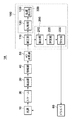
図1は、本発明の第1の実施形態におけるアブソリュートエンコーダ1Aの構成を示す概略ブロック図である。アブソリュートエンコーダ1Aは、産業用装置(加工装置)や計測装置に好適に用いられる。アブソリュートエンコーダ1Aは、本実施形態では、位置(絶対位置)を計測するリニアエンコーダであるが、角度(絶対角度)を計測するロータリーエンコーダであってもよい。
<First Embodiment>
FIG. 1 is a schematic block diagram showing a configuration of an absolute encoder 1A according to the first embodiment of the present invention. The absolute encoder 1A is suitably used for industrial devices (processing devices) and measuring devices. In the present embodiment, the absolute encoder 1A is a linear encoder that measures a position (absolute position), but may be a rotary encoder that measures an angle (absolute angle).
アブソリュートエンコーダ1Aは、図1に示すように、光源10と、スケール20と、検出部30と、増幅部40と、AD変換部50と、処理部100とを有する。
As shown in FIG. 1, the
光源10は、LEDなどを含み、ドライバ60によって駆動されてスケール20を照射する光を射出する。スケール20には、擬似乱数コード、例えば、M系列巡回符号が透過膜又は反射膜で形成されているため、スケール20を通過した光は、擬似乱数コードに応じた光強度となる。検出部30は、例えば、CMOSイメージセンサやCCDセンサなどの光電変換素子で構成され、スケール20からの光を検出する。
The
検出部30から出力された信号(光強度信号)は、電流/電圧変換アンプ(不図示)によって電圧信号に変換される。かかる電圧信号は、必要に応じて、増幅部40で増幅される。AD変換部50は、増幅部40から出力されたアナログ信号をデジタル信号に変換する。処理部100は、AD変換部50から出力されたデジタル信号(即ち、検出部30から出力される信号)に基づいて、スケール20の絶対位置を求めるための信号処理を行う。
The signal (light intensity signal) output from the
処理部100は、FPGA(Filed Programable Allay)やDSP(Digital Signal Processor)などの高速デジタル信号処理器で構成される。処理部100は、補正部110と、校正部200と、スケール20の絶対位置を算出する算出部300とを有する。また、校正部200は、本実施形態では、抽出部210と、特定部220と、設定部230とを含む。算出部300は、比較部120と、位置算出部130とを含む。
The
補正部110は、必要に応じて、AD変換部50から出力された信号にオフセット補正やゲイン補正を施す。比較部120は、補正部110から出力された信号を閾値と比較して、閾値よりも大きいか小さいかを表す2値信号(0又は1の信号)に変換する。位置算出部130は、比較部120からの2値信号に基づいて、スケール20の絶対位置を算出する。
The
ここで、図2を参照して、アブソリュートエンコーダ1Aの光源10から検出部30までの構成の一例、及び、検出部30から出力される光強度信号の一例を説明する。
Here, an example of a configuration from the
光源10から射出された光は、コリメータレンズ12を介して平行光となり、スケール20に照射される。本実施形態では、スケール20には、互いに透過率の異なる第1マーク22、第2マーク24及び第3マーク26が形成(配列)されている(即ち、3値の透過率を有する)。例えば、第1マーク22は、100%の透過率を有し、第2マーク24は、50%の透過率を有し、第3マーク26は、0%の透過率を有する。この場合、検出部30から出力される光強度信号は、第1マーク22(を透過した光)に対応する第1ピーク値と、第2マーク24(を透過した光)に対応する第2ピーク値と、第3マーク26に対応する最低値とを含む。このような光強度信号は、図2に示すように、第1ピーク値と第2ピーク値とを含むピーク値が周期的に現れる周期信号である。
The light emitted from the
検出部30から出力される光強度信号(第1ピーク及び第2ピーク)は、比較部120において、閾値と比較され、閾値以上であれば1、閾値以下であれば0とする2値信号に変換される。換言すれば、検出部30から出力される光強度信号における第1ピーク値及び第2ピーク値を2値化して符号列を得る。かかる2値信号は、スケール20の位置に応じた擬似乱数コードを示し、位置算出部130において、擬似乱数コードと絶対位置との対応関係を表すテーブルを参照することで、スケール20の絶対位置を算出する。光強度信号に含まれるピーク値の周期又は最低値の周期は、一定であり、通常、数μm〜数百μm程度の間隔である。光強度信号に含まれるピーク値の周期又は最低値の周期が短いほど、絶対位置の分解能は向上し、光強度信号に含まれるピーク値の周期又は最低値の周期が長いほど、絶対位置の分解能は低下する。
The light intensity signal (the first peak and the second peak) output from the
例えば、光強度信号に含まれるピーク値の周期又は最低値の周期が100μm、擬似乱数コードが16bitである場合、絶対位置の分解能は100μmであり、最大計測可能レンジは100μmの16bit倍に相当する6.5536mとなる。また、光強度信号に含まれるピーク値の周期又は最低値の周期が100μm、擬似乱数コードが12bitである場合には、絶対位置の分解能は100μmであるが、最大計測可能レンジは0.4096mとなる。
For example, when the peak value period or the minimum value period included in the light intensity signal is 100 μm and the pseudo random number code is 16 bits, the resolution of the absolute position is 100 μm, and the maximum measurable range corresponds to 16
光強度信号に含まれるピーク値の周期又は最低値の周期に対して複数の光電変換素子が配置されるように、検出部30は構成されている。例えば、1周期に対して10個の光電変換素子が配置されるように検出部30を構成する場合、擬似乱数コードを16bitとすると、検出部30を構成する光電変換素子の数は160個となる。
The
3値の透過率(又は反射率)を有するスケール20を用いたアブソリュートエンコーダ1Aの詳細については、特許文献3に開示されている。アブソリュートエンコーダ1Aでは、スケール20からの光の光強度を3値としているため、アブソリュートエンコーダとして絶対位置を計測すると共に、位相分割によりインクリメンタルエンコーダと同等の計測分解能及び精度を実現することができる。このように、アブソリュートエンコーダ1Aは、擬似乱数コードによる2値の透過率を有するアブソリュートスケール及び規則正しく周期的な強度変化を繰り返す2値の透過率を有するインクリメントスケールの2つのスケールを有していない。但し、アブソリュートエンコーダ1Aは、3値の透過率を有するスケール20を有しているため、1つのスケールであっても、高計測分解能、且つ、高精度なアブソリュートエンコーダを構成することが可能である。
The details of the absolute encoder 1A using the
アブソリュートエンコーダ1Aにおいて、3値の透過率を有するスケール20による擬似乱数コードに従った光強度信号は、通常のインクリメンタルエンコーダのような一定振幅を有する正弦波信号とはならない。スケール20には、100%の透過率を有する第1マーク22と50%の透過率を有する第2マーク24とが乱数として形成されている。従って、検出部30では、第1マーク22に対応する第1ピーク値と第2マーク24に対応する第2ピーク値とがランダムに検出される。
In the absolute encoder 1A, the light intensity signal according to the pseudo random number code by the
一方、上述したように、産業用装置や計測装置に用いられるエンコーダは、環境変化(温度変化)、経時変化、スケールや光源及び検出部(光電変換素子)の取り付け、スケールの製造ばらつきなどに関わらず、位置又は角度を高精度に計測する必要がある。従って、環境変化、経時変化、スケールや光源及び検出部の取り付け、スケールの製造ばらつきなどに関わらず、検出部から出力され、処理部で処理される光強度信号を安定化することが必要となる。 On the other hand, as described above, encoders used in industrial devices and measuring devices are related to environmental changes (temperature changes), changes over time, scales, light sources and detectors (photoelectric conversion elements), and manufacturing variations of scales. First, it is necessary to measure the position or angle with high accuracy. Therefore, it is necessary to stabilize the light intensity signal that is output from the detection unit and processed by the processing unit regardless of environmental changes, changes over time, scale and light source and detection unit mounting, scale manufacturing variations, and the like. .
例えば、検出部30から出力された光強度信号が正常である場合と、検出部30から出力された光強度信号が異常である場合(環境変化、経時変化、スケールや光源及び検出部の取り付け、スケールの製造ばらつきなどの影響を受けている場合)とを図3に示す。
For example, when the light intensity signal output from the
図3(a)は、検出部30から出力される光強度信号が正常である場合を示している。この場合、比較部120において、光強度信号(に含まれる第1ピーク値及び第2ピーク値)と閾値とを比較すると、かかる光強度信号は、正常な2値信号に変換される。具体的には、図3(a)に示すように、光強度信号に含まれる1番目のピーク値Pk1及び2番目のピーク値Pk2(第1ピーク値)は閾値よりも大きいため、比較部120から出力される2値信号は、「1」、「1」となる。一方、光強度信号に含まれる3番目のピーク値Pk3及び4番目のピーク値Pk4(第2ピーク値)は閾値よりも小さいため、比較部120から出力される2値信号は、「0」、「0」となる。また、光強度信号に含まれる5番目のピーク値Pk5(第1ピーク値)は閾値よりも大きいため、比較部120から出力される2値信号は、「1」となる。従って、比較部120から出力される2値信号は、「1、1、0、0、1」となる。
FIG. 3A shows a case where the light intensity signal output from the
図3(b)は、検出部30から出力される光強度信号が小さい場合を示している。この場合、比較部120において、光強度信号と閾値とを比較すると、光強度信号に含まれる全てのピーク値Pk1乃至Pk5が閾値未満となるため、比較部120から出力される2値信号は、「0、0、0、0、0」となる。このように、比較部120から誤った2値信号が出力されると、位置算出部130は、誤った絶対位置を算出してしまう。
FIG. 3B shows a case where the light intensity signal output from the
図3(c)は、検出部30から出力される光強度信号が大きい場合を示している。この場合、比較部120において、光強度信号と閾値とを比較すると、光強度信号に含まれる全てのピーク値Pk1乃至Pk5が閾値を超えているため、比較部120から出力される2値信号は、「1、1、1、1、1」となる。このように、比較部120から誤った2値信号が出力されると、位置算出部130は、誤った絶対位置を算出してしまう。
FIG. 3C shows a case where the light intensity signal output from the
そこで、アブソリュートエンコーダ1Aは、上述したような絶対位置の算出処理(算出部300による算出処理)が正しく行われるように、校正部200を有する。校正部200は、光強度信号に含まれる第1ピーク値が閾値よりも大きく、且つ、第2ピーク値が閾値よりも小さくなるように、検出部30から出力される光強度信号と閾値との関係を校正する。換言すれば、校正部200は、光強度信号に含まれる第1ピーク値が2値化のための閾値よりも大きく、且つ、第1ピーク値より小さい第2ピーク値が2値化のための閾値より小さくなるように、校正を行う機能を有する。
Therefore, the absolute encoder 1A includes the
図1、図3及び図4を参照して、校正部200による校正について具体的に説明する。上述したように、スケール20には、100%の透過率を有する第1マーク22と50%の透過率を有する第2マーク24とが乱数として形成されている。従って、検出部30では、第1マーク22に対応する第1ピーク値(最大ピーク値)と第2マーク24に対応する第2ピーク値(中間ピーク値)とがランダムに検出される。ここで、光強度信号に含まれる最低値と次の最低値との間隔、或いは、ピーク値と次のピーク値との間隔は、スケール20に形成されるマークの間隔によって決定され、それらの周期は一定である。本実施形態では、それらの周期を光強度信号の1周期とする。
The calibration by the
図4に示すように、S402において、抽出部210は、検出部30からの光強度信号(本実施形態では、補正部110からのオフセット補正やゲイン補正が施された信号)の1周期ごとに最大値(ピーク値)を抽出する。例えば、図3(a)乃至図3(c)に示す光強度信号に対して、抽出部210は、1周期ごとの最大値、即ち、最低値から次の最低値までの間隔におけるピーク値Pk1乃至Pk5を抽出する。
As illustrated in FIG. 4, in S <b> 402, the
S404において、特定部220は、S402で抽出した最大値から、最も大きな最大値(第1最大値)Vmaxと、最も小さな最大値(第2最大値)Vminとを特定する。例えば、図3(b)及び図3(c)では、特定部220は、ピーク値Pk1乃至Pk5から、ピーク値Pk1を最も大きな最大値Vmaxとして特定し、ピーク値Pk4を最も小さな最大値Vminとして特定する。
In S404, the specifying
S406において、設定部230は、S404で特定された最も大きな最大値Vmaxと予め定められた基準値(第1基準値)VLとを比較し、S404で特定された最も小さな最大値Vminと予め定められた基準値(第2基準値)VHとを比較する。ここで、基準値VLは、閾値よりも大きな値であり、基準値VHは、閾値よりも小さな値である。また、S406では、S404で特定された最も大きな最大値Vmax及び最も小さな最大値Vminと閾値とを比較してもよい。
In S406, the
S408において、設定部230は、S406での比較結果に基づいて、最大値Vmaxが基準値VL以上(第1基準値以上)となり、最大値Vminが基準値VH以下(第2基準値以下)となるように、光源10から射出される光の強度を設定する。
In S408, based on the comparison result in S406, the
例えば、図3(b)では、設定部230は、最も大きな最大値Vmaxが、基準値VLを下限値としてそれ以上となるように、光源10を駆動する電流値の下限値ILを決定する。また、設定部230は、最も小さな最大値Vminが、基準値VHを上限値としてそれ以下となるように、光源10を駆動する電流値の上限値IHを決定する。ここで、光源10を駆動する電流値と光の強度との関係は、予め計測して取得してもよいし、設計値を用いてもよい。また、基準値VL及びVHではなく、閾値からの比率によって下限値及び上限値を決めておき、電流値の下限値IL及び上限値IHを決定してもよい。そして、設定部230は、このように決定した下限値IL以上、且つ、上限値IH以下となるように、光源10の駆動電流値をドライバ60に設定する。例えば、光源10の駆動電流値は、下限値ILと上限値IHとの平均値としてもよい。
For example, in FIG. 3 (b), the
このように光源10の駆動電流値が設定されることで、光強度信号に含まれる最も大きな最大値Vmaxは、基準値VLを下限値としてそれ以上となり、光強度信号に含まれる最も小さな最大値Vminは、基準値VHを上限値としてそれ以下となる。従って、図3(a)に示すように、閾値に対して、光強度信号に含まれるピーク値Pk1乃至Pk5が正しく2値に変換され、比較部120から出力される2値信号は、「1、1、0、0、1」となる。
By setting the drive current value of the
これにより、アブソリュートエンコーダ1Aでは、環境変化、経時変化、スケール20や光源10及び検出部30の取り付け、スケール20の製造ばらつきなどに関わらず、検出部30から出力され、処理部100で処理される光強度信号を安定化することができる。従って、アブソリュートエンコーダ1Aは、スケール20の絶対位置を高精度に計測することができる。
As a result, in the absolute encoder 1A, the output is output from the
本実施形態では、スケール20に形成する透過率(又は反射率)を0%、50%及び100%の3値としたが、これらの値に限定されるものではなく、任意の3値でよい。例えば、スケール20に0%や100%の透過率を容易に形成することができない場合には、スケール20に形成する透過率を10%、40%及び90%や20%、40%及び80%などとしてもよい。この場合にも、光強度信号に含まれる最も大きな最大値Vmax及び最も小さな最大値Vminを特定して、3値の比率に応じた下限値及び上限値を決定し、その条件を満足するように光源10の駆動電流値を設定する。これにより、閾値に対して、光強度信号に含まれるピーク値Pk1乃至Pk5が正しく2値に変換され(即ち、比較部120から正しい2値信号が出力され)、スケール20の絶対位置を高精度に計測することが可能となる。例えば、スケール20に形成する透過率が20%、40%及び80%である場合、最大ピーク値は80%付近の光強度となり、中間ピーク値は40%付近の光強度となる。そこで、閾値を60%とし、下限値を65%、上限値を55%としてこれを満足するように光源10の駆動電流値を設定することで、光強度信号を安定化してスケール20の絶対位置を高精度に計測することができる。
In the present embodiment, the transmittance (or reflectance) formed on the
このように、アブソリュートエンコーダ1Aによれば、光強度信号が一定振幅を有する正弦波信号ではなく、例えば、3値を有するランダム信号であっても、スケール20の位置を高精度に計測することができる。
Thus, according to the absolute encoder 1A, the position of the
<第2の実施形態>
図5は、本発明の第2の実施形態におけるアブソリュートエンコーダ1Bの構成を示す概略ブロック図である。アブソリュートエンコーダ1Bは、アブソリュートエンコーダ1Aと比較して、処理部100B、詳細には、校正部200Bが異なる。校正部200Bは、本実施形態では、抽出部210と、特定部220と、ゲイン設定部240とを含む。
<Second Embodiment>
FIG. 5 is a schematic block diagram showing a configuration of an
図3及び図5を参照して、校正部200Bによる校正について具体的に説明する。第1の実施形態と同様に、抽出部210は、光強度信号の1周期ごとに最大値を抽出し、特定部220は、抽出部210で抽出された最大値から、最も大きな最大値Vmaxと、最も小さな最大値Vminとを特定する。
With reference to FIG.3 and FIG.5, the calibration by the
ゲイン設定部240は、特定部220で特定された最も大きな最大値Vmaxと予め定められた基準値VLとを比較し、特定部220で特定された最も小さな最大値Vminと予め定められた基準値VHとを比較する。また、ゲイン設定部240は、その比較結果に基づいて、基準値VLを最大値Vmaxで除算した値以上、且つ、基準値VHを最大値Vminで除算した値以下となるように、増幅部40における信号の増幅率(ゲイン)を設定する。
The
例えば、図3(b)では、ゲイン設定部240は、最も大きな最大値Vmaxから、基準値VLを下限値とする下限ゲインGL=VL/Vmaxを算出し、最も小さな最大値Vminから、基準値VHを上限値とする上限ゲインGH=VH/Vminを算出する。そして、ゲイン設定部240は、下限ゲインGL以上、且つ、上限ゲインGH以下となるように増幅部40におけるゲインを設定する。例えば、増幅部40におけるゲインは、下限ゲインGLと上限ゲインGHとの平均値としてもよい。
For example, in FIG. 3B, the
このように増幅部40におけるゲインが設定されることで、光強度信号に含まれる最も大きな最大値Vmaxは、基準値VLを下限値としてそれ以上となり、光強度信号に含まれる最も小さな最大値Vminは、基準値VHを上限値としてそれ以下となる。従って、図3(a)に示すように、閾値に対して、光強度信号に含まれるピーク値Pk1乃至Pk5が正しく2値に変換され、比較部120から出力される2値信号は、「1、1、0、0、1」となる。
By setting the gain in the amplifying
アブソリュートエンコーダ1Bによれば、環境変化、経時変化、スケール20や光源10及び検出部30の取り付け、スケール20の製造ばらつきなどに関わらず、検出部30から出力され、処理部100Bで処理される光強度信号を安定化することができる。従って、アブソリュートエンコーダ1Bは、スケール20の絶対位置を高精度に計測することができる。
According to the
<第3の実施形態>
図6は、本発明の第3の実施形態におけるアブソリュートエンコーダ1Cの構成を示す概略ブロック図である。アブソリュートエンコーダ1Cは、アブソリュートエンコーダ1Aと比較して、処理部100C、詳細には、校正部200Cが異なる。校正部200Cは、本実施形態では、抽出部210と、特定部220と、時間設定部250とを含む。
<Third Embodiment>
FIG. 6 is a schematic block diagram showing the configuration of an
図3及び図6を参照して、校正部200Cによる校正について具体的に説明する。第1の実施形態と同様に、抽出部210は、光強度信号の1周期ごとに最大値を抽出し、特定部220は、抽出部210で抽出された最大値から、最も大きな最大値Vmaxと、最も小さな最大値Vminとを特定する。
With reference to FIG.3 and FIG.6, the calibration by the
時間設定部250は、特定部220で特定された最も大きな最大値Vmaxと予め定められた基準値VLとを比較し、特定部220で特定された最も小さな最大値Vminと予め定められた基準値VHとを比較する。また、時間設定部250は、その比較結果に基づいて、基準値VLを最大値Vmaxで除算した値以上、且つ、基準値VHを最大値Vminで除算した値以下となるように、検出部30を構成する光電変換素子の蓄積時間を設定する。
The
例えば、図3(b)では、時間設定部250は、最も大きな最大値Vmaxから、基準値VLを下限値とする下限蓄積時間比率TL=VL/Vmaxを算出する。同様に、時間設定部250は、最も小さな最大値Vminから、基準値VHを上限値とする上限蓄積時間比率TH=VH/Vminを算出する。そして、時間設定部250は、下限蓄積時間比率TL以上、且つ、上限蓄積時間比率TH以下となるように検出部30を構成する光電変換素子の蓄積時間を設定する。例えば、検出部30を構成する光電変換素子の蓄積時間は、下限蓄積時間比率TLと上限蓄積時間比率THとの平均値としてもよい。光電変換素子の蓄積時間を長くすると、検出される光強度は増加し、光電変換素子の蓄積時間を短くすると、検出される光強度は低下する。
For example, in FIG. 3B, the
このように光電変換素子の蓄積時間が設定されることで、光強度信号に含まれる最も大きな最大値Vmaxは、基準値VLを下限値としてそれ以上となり、光強度信号に含まれる最も小さな最大値Vminは、基準値VHを上限値としてそれ以下となる。従って、図3(a)に示すように、閾値に対して、光強度信号に含まれるピーク値Pk1乃至Pk5が正しく2値に変換され、比較部120から出力される2値信号は、「1、1、0、0、1」となる。
By setting the accumulation time of the photoelectric conversion element in this way, the largest maximum value V max included in the light intensity signal becomes more than the reference value V L as the lower limit value, and is the smallest included in the light intensity signal. The maximum value V min is lower than the reference value V H as an upper limit value. Therefore, as shown in FIG. 3A, the peak values Pk1 to Pk5 included in the light intensity signal are correctly converted into binary values with respect to the threshold value, and the binary signal output from the
アブソリュートエンコーダ1Cによれば、環境変化、経時変化、スケール20や光源10及び検出部30の取り付け、スケール20の製造ばらつきなどに関わらず、検出部30から出力され、処理部100Cで処理される光強度信号を安定化することができる。従って、アブソリュートエンコーダ1Cは、スケール20の絶対位置を高精度に計測することができる。
According to the
<第4の実施形態>
図7は、本発明の第4の実施形態におけるアブソリュートエンコーダ1Dの構成を示す概略ブロック図である。アブソリュートエンコーダ1Dは、アブソリュートエンコーダ1Aと比較して、処理部100D、詳細には、校正部200Dが異なる。校正部200Dは、本実施形態では、抽出部210と、特定部220と、閾値設定部260とを含む。
<Fourth Embodiment>
FIG. 7 is a schematic block diagram showing a configuration of an
図3及び図7を参照して、校正部200Dによる校正について具体的に説明する。第1の実施形態と同様に、抽出部210は、光強度信号の1周期ごとに最大値を抽出し、特定部220は、抽出部210で抽出された最大値から、最も大きな最大値Vmaxと、最も小さな最大値Vminとを特定する。
With reference to FIG.3 and FIG.7, the calibration by
閾値設定部260は、最も大きな最大値Vmaxよりも小さく、且つ、最も小さな最大値Vminよりも大きくなるように、比較部120における閾値を設定する。例えば、比較部120における閾値は、最も大きな最大値Vmaxと最も小さな最大値Vminとの平均値としてもよい。
このように比較部120における閾値が設定されることで、光強度信号に含まれる最も大きな最大値Vmaxは、閾値以上となり、光強度信号に含まれる最も小さな最大値Vminは、閾値以下となる。従って、図3(a)に示すように、閾値に対して、光強度信号に含まれるピーク値Pk1乃至Pk5が正しく2値に変換され、比較部120から出力される2値信号は、「1、1、0、0、1」となる。
By setting the threshold value in the
アブソリュートエンコーダ1Dによれば、環境変化、経時変化、スケール20や光源10及び検出部30の取り付け、スケール20の製造ばらつきなどに関わらず、検出部30から出力され、処理部100Dで処理される光強度信号を安定化することができる。従って、アブソリュートエンコーダ1Dは、スケール20の絶対位置を高精度に計測することができる。
According to the
<第5の実施形態>
図8は、本発明の第5の実施形態におけるアブソリュートエンコーダ1Eの構成を示す概略ブロック図である。アブソリュートエンコーダ1Eは、アブソリュートエンコーダ1Aと比較して、処理部100E、詳細には、校正部200Eが異なる。校正部200Eは、本実施形態では、抽出部210と、特定部220と、設定部230と、保持部270とを含む。
<Fifth Embodiment>
FIG. 8 is a schematic block diagram showing a configuration of an
検出部30から出力される光強度信号は、環境変化、経時変化、スケール20や光源10及び検出部30の取り付けの他に、スケール20の製造ばらつきによっても異なる場合がある。例えば、スケール20に100%の透過率を有する第1マーク22、50%の透過率を有する第2マーク24及び0%の透過率を有する第3マーク26を形成すると、製造ばらつきによって、数%から数十%の透過率のばらつきが生じる場合がある。例えば、スケール20に形成されるマークの透過率のばらつきの最大値を+ΔP1及び−ΔP2とする。これらの透過率のばらつきの最大値は、スケール20を実際に計測してもよいし、設計値を用いてもよい。スケール20に形成されるマークの透過率のばらつきの最大値+ΔP1及び−ΔP2は、保持部270に保持される。
The light intensity signal output from the
図9は、スケール20に形成されるマークの透過率(又は反射率)のばらつきが生じた場合において、検出部30から出力される光強度信号の一例を示す図である。図9を参照するに、第1マーク22に対応する第1ピーク値であるピーク値Pk1、Pk2及びPk5が同じ光強度とならずに、また、第2マーク24に対応する第2ピーク値であるピーク値Pk3及ぶPk4が同じ光強度とならずに、ばらついている。
FIG. 9 is a diagram illustrating an example of a light intensity signal output from the
図3、図8及び図10を参照して、校正部200Eによる校正について具体的に説明する。S902及びS904は、図4に示すS402及びS404と同様であるため、ここでの詳細な説明は省略する。 The calibration by the calibration unit 200E will be specifically described with reference to FIGS. Since S902 and S904 are the same as S402 and S404 shown in FIG. 4, detailed description thereof is omitted here.
S906において、特定部220は、保持部270に保持された透過率のばらつきの最大値+ΔP1及び−ΔP2に基づいて、最も大きな最大値Vmax及び最も小さな最大値Vminから補正最大値Vmax_min及びVmin_maxを算出する。例えば、特定部220は、最大値Vmaxに対して、補正最大値Vmax_min=Vmax×(1−ΔP2)を算出する。補正最大値Vmax_minは、光強度が最も低くなる最大値である。また、特定部220は、最大値Vminに対して、補正最大値Vmin_max=Vmin×(1+ΔP1)を算出する。補正最大値Vmin_maxは、光強度が最も高くなる最小値である。
In S906, the specifying
S908において、設定部230は、S906で算出された補正最大値Vmax_minと予め定められた基準値VLとを比較し、S906で算出された補正最大値Vmin_maxと予め定められた基準値VHとを比較する。
In S908, the
S910において、設定部230は、S908での比較結果に基づいて、補正最大値Vmax_minが基準値VL以上となり、補正最大値Vmin_maxが基準値VH以下となるように、光源10から射出される光の強度を設定する。
In S910, the
このように光源10の駆動電流値が設定されることで、光強度信号に含まれる最も大きな最大値Vmaxは、基準値VLを下限値としてそれ以上となり、光強度信号に含まれる最も小さな最大値Vminは、基準値VHを上限値としてそれ以下となる。従って、図3(a)に示すように、閾値に対して、光強度信号に含まれるピーク値Pk1乃至Pk5が正しく2値に変換され、比較部120から出力される2値信号は、「1、1、0、0、1」となる。
By setting the drive current value of the
アブソリュートエンコーダ1Eによれば、スケール20に形成されるマークの透過率のばらつき(スケール20の製造ばらつき)を考慮して、検出部30から出力され、処理部100Bで処理される光強度信号を安定化することができる。従って、アブソリュートエンコーダ1Eは、スケール20の絶対位置を高精度に計測することができる。
According to the
本実施形態では、S910において、S908での比較結果に基づいて、光源10から射出される光の強度を設定しているが、これに限定されるものではない。S910においては、S908での比較結果に基づいて、第2の実施形態、第3の実施形態及び第4の実施形態のように、増幅部40におけるゲイン、光電変換素子の蓄積時間及び比較部120における閾値を設定してもよい。
In the present embodiment, in S910, the intensity of light emitted from the
<第6の実施形態>
本発明の第6の実施形態におけるアブソリュートエンコーダの構成は、第5の実施形態におけるアブソリュートエンコーダ1Eと同じである。図11は、スケール20に形成されるマークの透過率(又は反射率)のばらつきが生じた場合において、検出部30から出力される光強度信号の一例を示す図である。図11を参照するに、第1マーク22に対応する第1ピーク値であるピーク値Pk1、Pk2及びPk5が同じ光強度とならずに、また、第2マーク24に対応する第2ピーク値であるピーク値Pk3及ぶPk4が同じ光強度とならずに、ばらついている。
<Sixth Embodiment>
The configuration of the absolute encoder in the sixth embodiment of the present invention is the same as that of the
図11を参照して、校正部200Eによる校正について具体的に説明する。第5の実施形態と同様に、抽出部210は、光強度信号の1周期ごとに最大値を抽出し、特定部220は、抽出部210で抽出された最大値から、最も大きな最大値Vmaxと、最も小さな最大値Vminとを特定する(第1特定部)。
With reference to FIG. 11, the calibration by the calibration unit 200E will be specifically described. Similar to the fifth embodiment, the
また、特定部220は、最も大きな最大値Vmaxと最も小さな最大値Vminとの間の中間値(第1値)Vmidを算出する。そして、特定部220は、抽出部210で抽出された最大値から、最大値Vmaxよりも小さく、且つ、中間値Vmidよりも大きくて中間値Vmidに最も近い最大値(第3最大値)Vmax_minを特定する(第2特定部)。同様に、特定部220は、抽出部210で抽出された最大値から、最大値Vminよりも大きく、且つ、中間値Vmidよりも小さくて中間値Vmidに最も近い最大値(第4最大値)Vmin_maxを特定する(第2特定部)。ここで、中間値Vmidは、例えば、最も大きな最大値Vmaxと最も小さな最大値Vminとの平均値((Vmax+Vmin)/2)とすればよい。
Further, the specifying
例えば、図11では、特定部220は、ピーク値Pk1乃至Pk5から、ピーク値Pk1を最も大きな最大値Vmaxとして特定し、ピーク値Pk4を最も小さな最大値Vminとして特定し、その中間値Vmidを算出する。次いで、特定部220は、ピーク値Pk1乃至Pk5から、ピーク値Pk2を最大値Vmaxよりも小さく、且つ、中間値Vmidよりも大きくて中間値Vmidに最も近い最大値Vmax_minとして特定する。同様に、特定部220は、ピーク値Pk1乃至Pk5から、ピーク値Pk3を最大値Vminよりも大きく、且つ、中間値Vmidよりも小さくて中間値Vmidに最も近い最大値Vmin_maxとして特定する。このように、本実施形態では、ピーク値Pk1、Pk2及びPk5が同じ光強度とならず、また、ピーク値Pk3及ぶPk4が同じ光強度とならない場合であっても、閾値に近い最も大きな最大値と最も小さな最大値とを特定することができる。
For example, in FIG. 11, the identifying
設定部230は、特定部220で特定された最大値Vmax_minと予め定められた基準値VLとを比較し、特定部220で特定された最大値Vmin_maxと予め定められた基準値VHとを比較する。そして、設定部230は、その比較結果に基づいて、最大値Vmax_minが基準値VL以上となり、最大値Vmin_maxが基準値VH以下となるように、光源10から射出される光の強度を設定する。
The
このように光源10の駆動電流値が設定されることで、光強度信号に含まれる最も大きな最大値Vmaxは、基準値VLを下限値としてそれ以上となり、光強度信号に含まれる最も小さな最大値Vminは、基準値VHを上限値としてそれ以下となる。従って、図3(a)に示すように、閾値に対して、光強度信号に含まれるピーク値Pk1乃至Pk5が正しく2値に変換され、比較部120から出力される2値信号は、「1、1、0、0、1」となる。
By setting the drive current value of the
アブソリュートエンコーダ1Eによれば、スケール20に形成されるマークの透過率のばらつき(スケール20の製造ばらつき)を考慮して、検出部30から出力され、処理部100Bで処理される光強度信号を安定化することができる。従って、アブソリュートエンコーダ1Eは、スケール20の絶対位置を高精度に計測することができる。
According to the
本実施形態では、光源10から射出される光の強度を設定しているが、これに限定されるものではない。第2の実施形態、第3の実施形態及び第4の実施形態のように、増幅部40におけるゲイン、光電変換素子の蓄積時間及び比較部120における閾値を設定してもよい。
In the present embodiment, the intensity of light emitted from the
以上、本発明の好ましい実施形態について説明したが、本発明はこれらの実施形態に限定されないことはいうまでもなく、その要旨の範囲内で種々の変形及び変更が可能である。 As mentioned above, although preferable embodiment of this invention was described, it cannot be overemphasized that this invention is not limited to these embodiment, A various deformation | transformation and change are possible within the range of the summary.
Claims (5)
第1マークと第2マークとが配列されたスケールと、
前記スケールからの光を検出して、前記第1マークに対応する第1ピーク値と前記第2マークに対応する前記第1ピーク値より小さい第2ピーク値とを含むピーク値が周期的に現れる周期信号を出力する検出部と、
前記検出部から出力される周期信号における前記第1ピーク値及び前記第2ピーク値を2値化して符号列を得る処理部と、を有し、
前記処理部は、前記第1ピーク値が前記2値化のための閾値より大きく、且つ、前記第2ピーク値が前記閾値より小さくなるように、校正を行う機能を有し、
前記機能は、
前記周期信号の各周期の最大値のうち、最も大きな第1最大値と、最も小さな第2最大値と、前記第1最大値より小さく、且つ、前記第1最大値と前記第2最大値との間の第1値より大きくて前記第1値に最も近い第3最大値と、前記第2最大値より大きく、且つ、前記第1値より小さくて前記第1値に最も近い第4最大値とを特定し、
前記第3最大値の補正により得られた値が前記閾値より大きな第1基準値以上となり、前記第4最大値の補正により得られた値が前記閾値より小さな第2基準値以下となるように、前記校正を行う、
ことを特徴とするアブソリュートエンコーダ。 An absolute encoder,
A scale in which the first mark and the second mark are arranged;
When light from the scale is detected, a peak value including a first peak value corresponding to the first mark and a second peak value smaller than the first peak value corresponding to the second mark appears periodically. A detector that outputs a periodic signal;
A processing unit that binarizes the first peak value and the second peak value in the periodic signal output from the detection unit to obtain a code string,
The processing unit has a function of performing calibration so that the first peak value is larger than a threshold value for binarization and the second peak value is smaller than the threshold value,
The function is
Among the maximum values of each period of the periodic signal, the largest first maximum value, the smallest second maximum value, smaller than the first maximum value, and the first maximum value and the second maximum value, A third maximum value that is greater than the first value between and closest to the first value, and a fourth maximum value that is greater than the second maximum value and that is less than the first value and closest to the first value. And identify
Value obtained by the correction of the third maximum value becomes large first reference value or more than the threshold value, so that the value obtained by correcting the fourth maximum value is equal to or less than a small second reference value than the threshold value Perform the calibration,
An absolute encoder characterized by this.
Priority Applications (3)
| Application Number | Priority Date | Filing Date | Title |
|---|---|---|---|
| JP2012274051A JP6168762B2 (en) | 2012-12-14 | 2012-12-14 | Absolute encoder |
| EP13005718.5A EP2755000A3 (en) | 2012-12-14 | 2013-12-09 | Absolute encoder |
| US14/103,920 US9285245B2 (en) | 2012-12-14 | 2013-12-12 | Absolute encoder |
Applications Claiming Priority (1)
| Application Number | Priority Date | Filing Date | Title |
|---|---|---|---|
| JP2012274051A JP6168762B2 (en) | 2012-12-14 | 2012-12-14 | Absolute encoder |
Publications (3)
| Publication Number | Publication Date |
|---|---|
| JP2014119326A JP2014119326A (en) | 2014-06-30 |
| JP2014119326A5 JP2014119326A5 (en) | 2016-02-04 |
| JP6168762B2 true JP6168762B2 (en) | 2017-07-26 |
Family
ID=49752912
Family Applications (1)
| Application Number | Title | Priority Date | Filing Date |
|---|---|---|---|
| JP2012274051A Expired - Fee Related JP6168762B2 (en) | 2012-12-14 | 2012-12-14 | Absolute encoder |
Country Status (3)
| Country | Link |
|---|---|
| US (1) | US9285245B2 (en) |
| EP (1) | EP2755000A3 (en) |
| JP (1) | JP6168762B2 (en) |
Families Citing this family (5)
| Publication number | Priority date | Publication date | Assignee | Title |
|---|---|---|---|---|
| JP6533360B2 (en) * | 2013-10-30 | 2019-06-19 | キヤノン株式会社 | Position detection device, lens apparatus having the same, and imaging apparatus |
| JP2016014574A (en) * | 2014-07-01 | 2016-01-28 | キヤノン株式会社 | Absolute encoder |
| EP4172569A2 (en) * | 2020-06-26 | 2023-05-03 | Sanofi | Improvements of an optical sensing system of a drug delivery device |
| DE102021110583A1 (en) | 2021-04-26 | 2022-10-27 | Sick Ag | Sensor device and method for determining an absolute position |
| CN113255393B (en) * | 2021-07-07 | 2021-10-15 | 江苏东大集成电路系统工程技术有限公司 | Image binarization method and device, storage medium and computer equipment |
Family Cites Families (14)
| Publication number | Priority date | Publication date | Assignee | Title |
|---|---|---|---|---|
| AU6569380A (en) * | 1980-03-06 | 1981-09-10 | R.J. Reynolds Tobacco Company | Dynamic threshold detector |
| US4475034A (en) * | 1982-06-24 | 1984-10-02 | International Business Machines Corporation | Modular shaft encoder |
| JP3302865B2 (en) | 1995-11-02 | 2002-07-15 | 松下電器産業株式会社 | Motor speed detector |
| JP4290281B2 (en) * | 1999-06-10 | 2009-07-01 | 株式会社ハーモニック・ドライブ・システムズ | Absolute sensor |
| JP2001311630A (en) | 2000-02-22 | 2001-11-09 | Mitsutoyo Corp | Optical encoder |
| US6898744B1 (en) * | 2001-11-01 | 2005-05-24 | Louis J. Jannotta | Apparatus and methods for monitoring encoder signals |
| JP2004138386A (en) * | 2002-10-15 | 2004-05-13 | Canon Inc | Means for controlling digital encoder |
| JP2005337843A (en) * | 2004-05-26 | 2005-12-08 | Canon Inc | Optical encoder |
| US7046000B1 (en) * | 2004-11-17 | 2006-05-16 | Aisin Seiki Kabushiki Kaisha | Rotation detecting sensor |
| JP5086597B2 (en) * | 2006-10-05 | 2012-11-28 | 株式会社キーエンス | Optical displacement meter, optical displacement measuring method, optical displacement measuring program, computer-readable recording medium, and recorded device |
| JP5519325B2 (en) * | 2010-02-25 | 2014-06-11 | 株式会社日本自動車部品総合研究所 | Rotation detection device and DC motor device |
| JP5379761B2 (en) * | 2010-08-06 | 2013-12-25 | キヤノン株式会社 | Absolute encoder |
| JP5832088B2 (en) * | 2010-12-15 | 2015-12-16 | キヤノン株式会社 | Rotary encoder |
| JP6436616B2 (en) * | 2013-06-12 | 2018-12-12 | キヤノン株式会社 | Measuring device, measuring method, and processing device |
-
2012
- 2012-12-14 JP JP2012274051A patent/JP6168762B2/en not_active Expired - Fee Related
-
2013
- 2013-12-09 EP EP13005718.5A patent/EP2755000A3/en not_active Withdrawn
- 2013-12-12 US US14/103,920 patent/US9285245B2/en not_active Expired - Fee Related
Also Published As
| Publication number | Publication date |
|---|---|
| EP2755000A2 (en) | 2014-07-16 |
| EP2755000A3 (en) | 2017-11-08 |
| US9285245B2 (en) | 2016-03-15 |
| US20140166865A1 (en) | 2014-06-19 |
| JP2014119326A (en) | 2014-06-30 |
Similar Documents
| Publication | Publication Date | Title |
|---|---|---|
| JP6168762B2 (en) | Absolute encoder | |
| JP6355827B2 (en) | Absolute encoder | |
| JP5379761B2 (en) | Absolute encoder | |
| JP5787513B2 (en) | Absolute rotary encoder | |
| US8823367B2 (en) | Rotation angle detection apparatus | |
| US8325066B2 (en) | Photoelectric encoder | |
| JP5832088B2 (en) | Rotary encoder | |
| KR20120093387A (en) | Calibration method and angle measuring method for an angle measuring device, and angle measuring device | |
| US8618467B2 (en) | Absolute encoder that detects an absolute position of an object | |
| JP5203024B2 (en) | Absolute position measuring encoder | |
| JP2019517004A (en) | Adaptive fiducial mark detection process | |
| JP5824342B2 (en) | Linear encoder | |
| US9880028B2 (en) | Absolute encoder | |
| JP2014119326A5 (en) | ||
| CN103090799B (en) | Displacement Detecting Device, and Displacement Detecting Method | |
| WO2018163424A1 (en) | Absolute encoder | |
| JP5553669B2 (en) | Optical absolute position measurement encoder | |
| US20140145071A1 (en) | Absolute encoder and method of obtaining absolute position | |
| JP5974154B2 (en) | Rotary encoder | |
| EP4336149A1 (en) | Position encoding apparatus and method | |
| JP7066264B2 (en) | Encoder and encoder control method | |
| JP2014098666A (en) | Incremental encoder |
Legal Events
| Date | Code | Title | Description |
|---|---|---|---|
| A521 | Request for written amendment filed |
Free format text: JAPANESE INTERMEDIATE CODE: A523 Effective date: 20151214 |
|
| A621 | Written request for application examination |
Free format text: JAPANESE INTERMEDIATE CODE: A621 Effective date: 20151214 |
|
| A977 | Report on retrieval |
Free format text: JAPANESE INTERMEDIATE CODE: A971007 Effective date: 20161027 |
|
| A131 | Notification of reasons for refusal |
Free format text: JAPANESE INTERMEDIATE CODE: A131 Effective date: 20161125 |
|
| A521 | Request for written amendment filed |
Free format text: JAPANESE INTERMEDIATE CODE: A523 Effective date: 20170116 |
|
| TRDD | Decision of grant or rejection written | ||
| A01 | Written decision to grant a patent or to grant a registration (utility model) |
Free format text: JAPANESE INTERMEDIATE CODE: A01 Effective date: 20170529 |
|
| A61 | First payment of annual fees (during grant procedure) |
Free format text: JAPANESE INTERMEDIATE CODE: A61 Effective date: 20170627 |
|
| R151 | Written notification of patent or utility model registration |
Ref document number: 6168762 Country of ref document: JP Free format text: JAPANESE INTERMEDIATE CODE: R151 |
|
| LAPS | Cancellation because of no payment of annual fees |