JP6165364B2 - Treatment tool and treatment system - Google Patents
Treatment tool and treatment system Download PDFInfo
- Publication number
- JP6165364B2 JP6165364B2 JP2016568264A JP2016568264A JP6165364B2 JP 6165364 B2 JP6165364 B2 JP 6165364B2 JP 2016568264 A JP2016568264 A JP 2016568264A JP 2016568264 A JP2016568264 A JP 2016568264A JP 6165364 B2 JP6165364 B2 JP 6165364B2
- Authority
- JP
- Japan
- Prior art keywords
- probe
- treatment
- sheath
- insulating member
- distal end
- Prior art date
- Legal status (The legal status is an assumption and is not a legal conclusion. Google has not performed a legal analysis and makes no representation as to the accuracy of the status listed.)
- Expired - Fee Related
Links
- 238000011282 treatment Methods 0.000 title claims description 202
- 239000000523 sample Substances 0.000 claims description 185
- 239000007788 liquid Substances 0.000 claims description 35
- 230000002093 peripheral effect Effects 0.000 claims description 18
- 238000007789 sealing Methods 0.000 claims description 9
- 230000001154 acute effect Effects 0.000 claims description 2
- 239000004615 ingredient Substances 0.000 claims 1
- 210000000988 bone and bone Anatomy 0.000 description 70
- 210000001519 tissue Anatomy 0.000 description 60
- 230000000740 bleeding effect Effects 0.000 description 40
- 230000023597 hemostasis Effects 0.000 description 32
- 230000004048 modification Effects 0.000 description 22
- 238000012986 modification Methods 0.000 description 22
- 238000000034 method Methods 0.000 description 12
- 238000003780 insertion Methods 0.000 description 7
- 230000037431 insertion Effects 0.000 description 7
- 238000009429 electrical wiring Methods 0.000 description 6
- 230000002439 hemostatic effect Effects 0.000 description 6
- 210000004204 blood vessel Anatomy 0.000 description 5
- 208000008558 Osteophyte Diseases 0.000 description 4
- 238000001356 surgical procedure Methods 0.000 description 4
- 238000003384 imaging method Methods 0.000 description 3
- 238000009413 insulation Methods 0.000 description 3
- 230000007246 mechanism Effects 0.000 description 3
- 229920005989 resin Polymers 0.000 description 3
- 239000011347 resin Substances 0.000 description 3
- BPKIGYQJPYCAOW-FFJTTWKXSA-I calcium;potassium;disodium;(2s)-2-hydroxypropanoate;dichloride;dihydroxide;hydrate Chemical compound O.[OH-].[OH-].[Na+].[Na+].[Cl-].[Cl-].[K+].[Ca+2].C[C@H](O)C([O-])=O BPKIGYQJPYCAOW-FFJTTWKXSA-I 0.000 description 2
- 239000003792 electrolyte Substances 0.000 description 2
- 239000007769 metal material Substances 0.000 description 2
- 239000002504 physiological saline solution Substances 0.000 description 2
- 238000010992 reflux Methods 0.000 description 2
- 239000000243 solution Substances 0.000 description 2
- 229910001069 Ti alloy Inorganic materials 0.000 description 1
- 230000008859 change Effects 0.000 description 1
- 230000015271 coagulation Effects 0.000 description 1
- 238000005345 coagulation Methods 0.000 description 1
- 239000011248 coating agent Substances 0.000 description 1
- 238000000576 coating method Methods 0.000 description 1
- 239000012141 concentrate Substances 0.000 description 1
- 239000004020 conductor Substances 0.000 description 1
- 230000007423 decrease Effects 0.000 description 1
- 238000007654 immersion Methods 0.000 description 1
- 239000011810 insulating material Substances 0.000 description 1
- 210000000281 joint capsule Anatomy 0.000 description 1
- 210000003127 knee Anatomy 0.000 description 1
- 230000007257 malfunction Effects 0.000 description 1
- 239000000463 material Substances 0.000 description 1
- 238000003825 pressing Methods 0.000 description 1
- 230000008569 process Effects 0.000 description 1
- 229920003002 synthetic resin Polymers 0.000 description 1
- 239000000057 synthetic resin Substances 0.000 description 1
- 230000000007 visual effect Effects 0.000 description 1
- XLYOFNOQVPJJNP-UHFFFAOYSA-N water Substances O XLYOFNOQVPJJNP-UHFFFAOYSA-N 0.000 description 1
Images


Classifications
-
- A—HUMAN NECESSITIES
- A61—MEDICAL OR VETERINARY SCIENCE; HYGIENE
- A61B—DIAGNOSIS; SURGERY; IDENTIFICATION
- A61B18/00—Surgical instruments, devices or methods for transferring non-mechanical forms of energy to or from the body
- A61B18/04—Surgical instruments, devices or methods for transferring non-mechanical forms of energy to or from the body by heating
- A61B18/12—Surgical instruments, devices or methods for transferring non-mechanical forms of energy to or from the body by heating by passing a current through the tissue to be heated, e.g. high-frequency current
- A61B18/14—Probes or electrodes therefor
- A61B18/148—Probes or electrodes therefor having a short, rigid shaft for accessing the inner body transcutaneously, e.g. for neurosurgery or arthroscopy
-
- A—HUMAN NECESSITIES
- A61—MEDICAL OR VETERINARY SCIENCE; HYGIENE
- A61B—DIAGNOSIS; SURGERY; IDENTIFICATION
- A61B17/00—Surgical instruments, devices or methods, e.g. tourniquets
- A61B17/16—Bone cutting, breaking or removal means other than saws, e.g. Osteoclasts; Drills or chisels for bones; Trepans
-
- A—HUMAN NECESSITIES
- A61—MEDICAL OR VETERINARY SCIENCE; HYGIENE
- A61B—DIAGNOSIS; SURGERY; IDENTIFICATION
- A61B1/00—Instruments for performing medical examinations of the interior of cavities or tubes of the body by visual or photographical inspection, e.g. endoscopes; Illuminating arrangements therefor
- A61B1/00112—Connection or coupling means
- A61B1/00114—Electrical cables in or with an endoscope
-
- A—HUMAN NECESSITIES
- A61—MEDICAL OR VETERINARY SCIENCE; HYGIENE
- A61B—DIAGNOSIS; SURGERY; IDENTIFICATION
- A61B1/00—Instruments for performing medical examinations of the interior of cavities or tubes of the body by visual or photographical inspection, e.g. endoscopes; Illuminating arrangements therefor
- A61B1/00112—Connection or coupling means
- A61B1/00121—Connectors, fasteners and adapters, e.g. on the endoscope handle
- A61B1/00124—Connectors, fasteners and adapters, e.g. on the endoscope handle electrical, e.g. electrical plug-and-socket connection
-
- A—HUMAN NECESSITIES
- A61—MEDICAL OR VETERINARY SCIENCE; HYGIENE
- A61B—DIAGNOSIS; SURGERY; IDENTIFICATION
- A61B1/00—Instruments for performing medical examinations of the interior of cavities or tubes of the body by visual or photographical inspection, e.g. endoscopes; Illuminating arrangements therefor
- A61B1/313—Instruments for performing medical examinations of the interior of cavities or tubes of the body by visual or photographical inspection, e.g. endoscopes; Illuminating arrangements therefor for introducing through surgical openings, e.g. laparoscopes
- A61B1/317—Instruments for performing medical examinations of the interior of cavities or tubes of the body by visual or photographical inspection, e.g. endoscopes; Illuminating arrangements therefor for introducing through surgical openings, e.g. laparoscopes for bones or joints, e.g. osteoscopes, arthroscopes
-
- A—HUMAN NECESSITIES
- A61—MEDICAL OR VETERINARY SCIENCE; HYGIENE
- A61B—DIAGNOSIS; SURGERY; IDENTIFICATION
- A61B17/00—Surgical instruments, devices or methods, e.g. tourniquets
- A61B17/32—Surgical cutting instruments
- A61B17/320016—Endoscopic cutting instruments, e.g. arthroscopes, resectoscopes
-
- A—HUMAN NECESSITIES
- A61—MEDICAL OR VETERINARY SCIENCE; HYGIENE
- A61B—DIAGNOSIS; SURGERY; IDENTIFICATION
- A61B17/00—Surgical instruments, devices or methods, e.g. tourniquets
- A61B17/32—Surgical cutting instruments
- A61B17/320068—Surgical cutting instruments using mechanical vibrations, e.g. ultrasonic
-
- A—HUMAN NECESSITIES
- A61—MEDICAL OR VETERINARY SCIENCE; HYGIENE
- A61B—DIAGNOSIS; SURGERY; IDENTIFICATION
- A61B18/00—Surgical instruments, devices or methods for transferring non-mechanical forms of energy to or from the body
-
- A—HUMAN NECESSITIES
- A61—MEDICAL OR VETERINARY SCIENCE; HYGIENE
- A61B—DIAGNOSIS; SURGERY; IDENTIFICATION
- A61B18/00—Surgical instruments, devices or methods for transferring non-mechanical forms of energy to or from the body
- A61B18/04—Surgical instruments, devices or methods for transferring non-mechanical forms of energy to or from the body by heating
- A61B18/12—Surgical instruments, devices or methods for transferring non-mechanical forms of energy to or from the body by heating by passing a current through the tissue to be heated, e.g. high-frequency current
- A61B18/1206—Generators therefor
-
- A—HUMAN NECESSITIES
- A61—MEDICAL OR VETERINARY SCIENCE; HYGIENE
- A61N—ELECTROTHERAPY; MAGNETOTHERAPY; RADIATION THERAPY; ULTRASOUND THERAPY
- A61N7/00—Ultrasound therapy
- A61N7/02—Localised ultrasound hyperthermia
-
- A—HUMAN NECESSITIES
- A61—MEDICAL OR VETERINARY SCIENCE; HYGIENE
- A61B—DIAGNOSIS; SURGERY; IDENTIFICATION
- A61B17/00—Surgical instruments, devices or methods, e.g. tourniquets
- A61B2017/00831—Material properties
- A61B2017/00862—Material properties elastic or resilient
-
- A—HUMAN NECESSITIES
- A61—MEDICAL OR VETERINARY SCIENCE; HYGIENE
- A61B—DIAGNOSIS; SURGERY; IDENTIFICATION
- A61B17/00—Surgical instruments, devices or methods, e.g. tourniquets
- A61B17/32—Surgical cutting instruments
- A61B17/320068—Surgical cutting instruments using mechanical vibrations, e.g. ultrasonic
- A61B2017/320069—Surgical cutting instruments using mechanical vibrations, e.g. ultrasonic for ablating tissue
-
- A—HUMAN NECESSITIES
- A61—MEDICAL OR VETERINARY SCIENCE; HYGIENE
- A61B—DIAGNOSIS; SURGERY; IDENTIFICATION
- A61B17/00—Surgical instruments, devices or methods, e.g. tourniquets
- A61B17/32—Surgical cutting instruments
- A61B17/320068—Surgical cutting instruments using mechanical vibrations, e.g. ultrasonic
- A61B2017/320071—Surgical cutting instruments using mechanical vibrations, e.g. ultrasonic with articulating means for working tip
-
- A—HUMAN NECESSITIES
- A61—MEDICAL OR VETERINARY SCIENCE; HYGIENE
- A61B—DIAGNOSIS; SURGERY; IDENTIFICATION
- A61B17/00—Surgical instruments, devices or methods, e.g. tourniquets
- A61B17/32—Surgical cutting instruments
- A61B17/320068—Surgical cutting instruments using mechanical vibrations, e.g. ultrasonic
- A61B2017/320088—Surgical cutting instruments using mechanical vibrations, e.g. ultrasonic with acoustic insulation, e.g. elements for damping vibrations between horn and surrounding sheath
-
- A—HUMAN NECESSITIES
- A61—MEDICAL OR VETERINARY SCIENCE; HYGIENE
- A61B—DIAGNOSIS; SURGERY; IDENTIFICATION
- A61B17/00—Surgical instruments, devices or methods, e.g. tourniquets
- A61B17/32—Surgical cutting instruments
- A61B17/320068—Surgical cutting instruments using mechanical vibrations, e.g. ultrasonic
- A61B2017/320089—Surgical cutting instruments using mechanical vibrations, e.g. ultrasonic node location
-
- A—HUMAN NECESSITIES
- A61—MEDICAL OR VETERINARY SCIENCE; HYGIENE
- A61B—DIAGNOSIS; SURGERY; IDENTIFICATION
- A61B18/00—Surgical instruments, devices or methods for transferring non-mechanical forms of energy to or from the body
- A61B2018/00053—Mechanical features of the instrument of device
- A61B2018/00059—Material properties
- A61B2018/00071—Electrical conductivity
- A61B2018/00083—Electrical conductivity low, i.e. electrically insulating
-
- A—HUMAN NECESSITIES
- A61—MEDICAL OR VETERINARY SCIENCE; HYGIENE
- A61B—DIAGNOSIS; SURGERY; IDENTIFICATION
- A61B18/00—Surgical instruments, devices or methods for transferring non-mechanical forms of energy to or from the body
- A61B2018/00053—Mechanical features of the instrument of device
- A61B2018/00107—Coatings on the energy applicator
-
- A—HUMAN NECESSITIES
- A61—MEDICAL OR VETERINARY SCIENCE; HYGIENE
- A61B—DIAGNOSIS; SURGERY; IDENTIFICATION
- A61B18/00—Surgical instruments, devices or methods for transferring non-mechanical forms of energy to or from the body
- A61B2018/00315—Surgical instruments, devices or methods for transferring non-mechanical forms of energy to or from the body for treatment of particular body parts
- A61B2018/00565—Bone
-
- A—HUMAN NECESSITIES
- A61—MEDICAL OR VETERINARY SCIENCE; HYGIENE
- A61B—DIAGNOSIS; SURGERY; IDENTIFICATION
- A61B18/00—Surgical instruments, devices or methods for transferring non-mechanical forms of energy to or from the body
- A61B2018/00571—Surgical instruments, devices or methods for transferring non-mechanical forms of energy to or from the body for achieving a particular surgical effect
- A61B2018/00595—Cauterization
-
- A—HUMAN NECESSITIES
- A61—MEDICAL OR VETERINARY SCIENCE; HYGIENE
- A61B—DIAGNOSIS; SURGERY; IDENTIFICATION
- A61B18/00—Surgical instruments, devices or methods for transferring non-mechanical forms of energy to or from the body
- A61B2018/00571—Surgical instruments, devices or methods for transferring non-mechanical forms of energy to or from the body for achieving a particular surgical effect
- A61B2018/00607—Coagulation and cutting with the same instrument
-
- A—HUMAN NECESSITIES
- A61—MEDICAL OR VETERINARY SCIENCE; HYGIENE
- A61B—DIAGNOSIS; SURGERY; IDENTIFICATION
- A61B18/00—Surgical instruments, devices or methods for transferring non-mechanical forms of energy to or from the body
- A61B2018/00982—Surgical instruments, devices or methods for transferring non-mechanical forms of energy to or from the body combined with or comprising means for visual or photographic inspections inside the body, e.g. endoscopes
-
- A—HUMAN NECESSITIES
- A61—MEDICAL OR VETERINARY SCIENCE; HYGIENE
- A61B—DIAGNOSIS; SURGERY; IDENTIFICATION
- A61B18/00—Surgical instruments, devices or methods for transferring non-mechanical forms of energy to or from the body
- A61B2018/00994—Surgical instruments, devices or methods for transferring non-mechanical forms of energy to or from the body combining two or more different kinds of non-mechanical energy or combining one or more non-mechanical energies with ultrasound
-
- A—HUMAN NECESSITIES
- A61—MEDICAL OR VETERINARY SCIENCE; HYGIENE
- A61B—DIAGNOSIS; SURGERY; IDENTIFICATION
- A61B18/00—Surgical instruments, devices or methods for transferring non-mechanical forms of energy to or from the body
- A61B18/04—Surgical instruments, devices or methods for transferring non-mechanical forms of energy to or from the body by heating
- A61B18/12—Surgical instruments, devices or methods for transferring non-mechanical forms of energy to or from the body by heating by passing a current through the tissue to be heated, e.g. high-frequency current
- A61B18/1206—Generators therefor
- A61B2018/1246—Generators therefor characterised by the output polarity
- A61B2018/126—Generators therefor characterised by the output polarity bipolar
-
- A—HUMAN NECESSITIES
- A61—MEDICAL OR VETERINARY SCIENCE; HYGIENE
- A61B—DIAGNOSIS; SURGERY; IDENTIFICATION
- A61B18/00—Surgical instruments, devices or methods for transferring non-mechanical forms of energy to or from the body
- A61B18/04—Surgical instruments, devices or methods for transferring non-mechanical forms of energy to or from the body by heating
- A61B18/12—Surgical instruments, devices or methods for transferring non-mechanical forms of energy to or from the body by heating by passing a current through the tissue to be heated, e.g. high-frequency current
- A61B18/14—Probes or electrodes therefor
- A61B2018/1472—Probes or electrodes therefor for use with liquid electrolyte, e.g. virtual electrodes
-
- A—HUMAN NECESSITIES
- A61—MEDICAL OR VETERINARY SCIENCE; HYGIENE
- A61B—DIAGNOSIS; SURGERY; IDENTIFICATION
- A61B18/00—Surgical instruments, devices or methods for transferring non-mechanical forms of energy to or from the body
- A61B18/04—Surgical instruments, devices or methods for transferring non-mechanical forms of energy to or from the body by heating
- A61B18/12—Surgical instruments, devices or methods for transferring non-mechanical forms of energy to or from the body by heating by passing a current through the tissue to be heated, e.g. high-frequency current
- A61B18/14—Probes or electrodes therefor
- A61B2018/1497—Electrodes covering only part of the probe circumference
Description
本発明は、関節鏡視下手術で用いられる処置具に関する。また、本発明は、その処置具を備える処置システムに関する。 The present invention relates to a treatment tool used in arthroscopic surgery. The present invention also relates to a treatment system including the treatment tool.
従来から超音波振動によって骨などの硬組織を処置する超音波手術具が知られている。例えば、特開2005−152098号公報に開示されている超音波ハンドピースは、超音波振動を出力する超音波振動機構と、超音波振動機構から伝達される振動により骨等の硬組織を切削するホーンと、を備えている。そして、ホーンは、本体部と、メス部とを有し、メス部が骨等の硬組織に当接して切削が行われる。 2. Description of the Related Art Conventionally, an ultrasonic surgical tool that treats a hard tissue such as a bone by ultrasonic vibration is known. For example, an ultrasonic handpiece disclosed in Japanese Patent Laid-Open No. 2005-152098 cuts a hard tissue such as a bone by an ultrasonic vibration mechanism that outputs ultrasonic vibration and vibration transmitted from the ultrasonic vibration mechanism. And a horn. And a horn has a main-body part and a knife part, and a knife part contact | abuts hard tissue, such as a bone, and cutting is performed.
ところで、超音波振動を用いて骨等の硬組織を切削している最中に血管を有する組織から出血が生じ、この出血により視野が阻害されることがある。しかしながら、前述した超音波ハンドピースは、止血機能を兼ね備えていないため、止血用デバイスに交換したうえで組織に対して止血を行う必要がある。このようにデバイスの交換を要する場合には、デバイスを交換する間に出血が進んで、術者が出血箇所を見失う可能性がある。したがってこのような場合には、出血箇所を含む広範囲の組織を焼灼する必要があり、術者の心理的負担が増大するとともに手術時間の増加にもつながる。 By the way, while cutting hard tissue such as bone using ultrasonic vibration, bleeding occurs from tissue having blood vessels, and the visual field may be obstructed by this bleeding. However, since the ultrasonic handpiece described above does not have a hemostatic function, it is necessary to perform hemostasis on the tissue after replacing the hemostatic device. When the device needs to be replaced in this way, bleeding may progress while the device is replaced, and the operator may lose sight of the bleeding site. Therefore, in such a case, it is necessary to cauterize a wide range of tissues including the bleeding site, which increases the psychological burden on the operator and increases the operation time.
本発明は、関節鏡視下手術において、切削処置と止血処置の両方を実施できる処置具および処置システムを提供することを目的とする。 An object of the present invention is to provide a treatment tool and a treatment system capable of performing both cutting treatment and hemostasis treatment in arthroscopic surgery.
前記目的を達成するために、本発明のある態様では、導電性の液体で満たされた環境下で使用される処置具は、超音波振動により処置対象部位を切削する先端部を有すると共に、前記先端部をバイポーラ電極における一方の極として機能させるプローブと、前記プローブを取り囲む中空のシースと、前記シースの先端側における一部の領域を除いて前記シースを覆う絶縁部材と、を備え、前記一部の領域は、前記バイポーラ電極における他方の極として機能する。 In order to achieve the above object, in one aspect of the present invention, a treatment tool used in an environment filled with a conductive liquid has a tip portion for cutting a treatment target site by ultrasonic vibration, and A probe that causes the tip to function as one pole of a bipolar electrode, a hollow sheath that surrounds the probe, and an insulating member that covers the sheath except for a part of the region on the tip side of the sheath. The region of the part functions as the other pole in the bipolar electrode.
また、前記目的を達成するために、本発明のある態様では、処置システムは、上記処置部と、処置具で処置する箇所を視認する内視鏡装置と、を備える。 In order to achieve the above object, according to an aspect of the present invention, a treatment system includes the treatment unit and an endoscope device that visually recognizes a place to be treated with a treatment tool.
本発明によれば、関節鏡視下手術において、切削処置と止血処置の両方を実施できる処置具および処置システムを提供できる。 According to the present invention, it is possible to provide a treatment tool and a treatment system capable of performing both cutting treatment and hemostasis treatment in arthroscopic surgery.
[第1の実施形態]
本発明の第1の実施形態について、図1乃至図10を参照して説明する。処置システム11は、処置対象部位として例えば、肩、膝、肘等の関節の処置に用いられる。より具体的には、図1に示すように、処置システム11は、関節における第1の骨12と第2の骨13との間の処置に用いられる。処置システム11は、処置具14と、処置具14を動作させるための電源ユニット37と、関節鏡15を含む内視鏡装置16と、を備える。[First Embodiment]
A first embodiment of the present invention will be described with reference to FIGS. The
図1に示すように、内視鏡装置16は、関節鏡15と、画像処理ユニット17と、表示ユニット18と、を備えている。
As shown in FIG. 1, the endoscope apparatus 16 includes an
関節鏡15は、挿入部21と、保持部22と、を備える。処置システム11を用いた処置においては、挿入部21の先端部が関節腔23に挿入される。保持部22には、ユニバーサルコード24の一端が接続されている。ユニバーサルコード24の他端は、画像プロセッサ等の画像処理ユニット17に接続されている。画像処理ユニット17は、モニタ等の表示ユニット18に電気的に接続されている。
The
挿入部21の先端部には、撮像素子が設けられている。撮像素子は、観察窓を通して、被写体を撮像する。撮像素子は、挿入部21の内部、保持部22の内部及びユニバーサルコード24の内部を通って延設される撮像ケーブルを介して、画像処理ユニット17に電気的に接続されている。画像処理ユニット17によって、撮像された被写体像が、画像処理される。そして、表示ユニット18に、画像処理された被写体像が表示される。なお、関節鏡15には、図示しない光源ユニットが接続され、光源ユニットから出射された光が被写体に照射される。
An image sensor is provided at the distal end of the
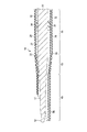
図1から図4に示すように、処置具14は、外殻を構成する保持部25と、保持部25内に収納された振動発生部26(トランスデューサ)と、振動発生部26に接続された棒状のプローブ27と、プローブ27の周囲を覆ってプローブ27を保護する中空(円筒形)のシース28と、保持部25に対して回転可能に固定されたノブ31(回転ノブ)と、シース28の内周面を覆う第1絶縁部材32と、シース28の外周面を覆う第2絶縁部材33と、プローブ27と第1絶縁部材32との間に設けられたシール部材34と、保持部25に設けられた複数のエネルギー入力ボタン35、38と、を備える。
As shown in FIGS. 1 to 4, the
なお、以下では、図1に示す矢印D1をプローブ27の先端方向とし、矢印D2をプローブ27の基端方向として説明を進める。
In the following description, the arrow D1 shown in FIG. 1 is the distal direction of the
保持部25には、ケーブル36の一端が接続されている。ケーブル36の他端は、電源ユニット37に接続されている。ノブ31は、保持部25に対してプローブ27の中心軸C周りに回転可能に取り付けられている。このノブ31は、プローブ27と図示しない連結機構を介して連結されている。そのため、ノブ31を保持部25に対して回転させることでプローブ27を一体的に中心軸C周りに回転させることができる。これによって、術者は、手術中にプローブ27を中心軸C周りに回転させることができる。
One end of a
保持部25には、例えば2個のエネルギー入力ボタン35が設けられている。エネルギー入力ボタン35の数は、2個に限られず3個以上であっても良いし、1個であっても良い。術者は、第1エネルギー入力ボタン35を操作することで、プローブ27を介して処置対象の骨組織(生体組織)に第1のエネルギー(超音波振動)を付与することができる。また、術者は、第2エネルギー入力ボタン38を操作することで、シース28を介して処置対象の骨組織(生体組織)に第2のエネルギー(高周波電流)を付与することができる。
The holding
図3に示すように、振動発生部26は、超音波振動子41と、ホーン部材42と、を備える。超音波振動子41には、電流を超音波振動に変化させる(本実施形態では例えば4つの)圧電素子43が設けられている。超音波振動子41には、第1の電気配線44(44a、44b)の一端が接続されている。第1の電気配線44(44a、44b)は、ケーブル36の内部を通り他端で電源ユニット37の超音波電流供給部45に接続されている。第1の電気配線44(44a、44b)を介して超音波電流供給部45から超音波振動子41に電力が供給されると、超音波振動子41において超音波振動が発生する。なお、第1の電気配線44aは、超音波電流供給部45のプラス極に接続され、第1の電気配線44bは、超音波電流供給部45のマイナス極に接続されている。
As shown in FIG. 3, the
超音波振動子41は、ホーン部材42に取付けられる。ホーン部材42は、金属材料によって形成されている。ホーン部材42には、プローブ27の先端方向へ向かうにつれて断面積が減少する略円錐形の断面変化部が設けられている。超音波振動子41で発生した超音波振動は、ホーン部材42に伝達され、断面変化部によって超音波振動の振幅が拡大される。
The
図4、図7Aに示すように、プローブ27は、例えば生体適合性のある金属材料(例えば、チタン合金等)によって棒状に形成されている。このプローブ27は、棒状に延びた軸部(本体部)51を有する。この軸部51の先端側(先端部)には、軸部51の延びている方向と交差する方向に熊手状(フック状)に突出した切削刃が形成された処置部52と、処置部52とは反対側(処置部52と対向する面)に平らに設けられた背部53と、処置部52と背部53との間の位置に設けられた一対の側部54と、を有している。処置部52と背部53との間の位置に、軸部51(プローブ27)の中心軸Cが位置している。プローブ27(軸部51)の基端部は、ホーン部材42と連結されている。そのため、プローブ27は、超音波振動子41で発生した超音波振動を伝達し、プローブ27の先端部(処置部52)によって骨を削る処置をすることができる。
As shown in FIGS. 4 and 7A, the
また、プローブ27は、図2に示すように、保持部25に設けられた第1プラグ46と電気的に接続されている。第1プラグ46は、2本ある第2の電気配線48のうちの一方の第2の電気配線48aの一端と電気的に接続されている。この第2の電気配線48aの他端は、電源ユニット37の高周波電流供給部47と電気的に接続されている。これにより、プローブ27は、バイポーラ処置を行なうためのバイポーラ電極の一方の極になる。なお、本実施形態では、第2の電気配線48aは、高周波電流供給部47のマイナス極と電気的に接続されている。そのため、プローブ27は、バイポーラ処置におけるリターン電極を構成することになる。
Further, as shown in FIG. 2, the
図4、図7Aに示すように、シース28は、保持部25に固定された円筒形の本体部55と、本体部55の先端側に設けられるとともにプローブ27の背部53を覆うように突出した突出部56と、プローブ27の処置部52および側部54を外界に露出させるように切り欠かれた切欠部57と、を有している。このシース28は、高周波電流を流すことができるよう導電性を有する材料から構成されている。
As shown in FIGS. 4 and 7A, the
切欠部57は、図7A、図8に示すように、プローブ27の延びている方向に対して斜めに形成されており、より具体的には、プローブ27の先端方向に行くにつれて、プローブ27の処置部52側の部分がそぎ落とされるように斜めに形成されている。より詳細には、切欠部57は、図8に示すように側面方向から見て、プローブ27の背部53のある方向に向けて凸になるように湾曲して形成されている。すなわち、切欠部57は、プローブ27の基端方向D2側においてプローブ27の延びている方向に対して斜めになっているが、プローブ27の先端方向D1側においてプローブ27の延びている方向と略平行な方向になっている。なお、図7Aに示すように、本実施形態では、シース28の突出部56の先端の位置は、プローブ27の先端の位置と一致している。
As shown in FIGS. 7A and 8, the
また、シース28は、図2に示すように、保持部25に設けられた第2プラグ58と電気的に接続されている。第2プラグ58は、2本ある第2の電気配線48のうちの他方の第2の電気配線48bの一端と電気的に接続されている。この第2の電気配線48bの他端は、電源ユニット37の高周波電流供給部47と電気的に接続されている。これにより、シース28は、バイポーラ処置を行なうためのバイポーラ電極の他方の極になる。なお、本実施形態では、第2の電気配線48bは、高周波電流供給部47のプラス極と電気的に接続されている。そのため、シース28は、バイポーラ処置におけるアクティブ電極を構成することになる。
Further, the
図4及び図7Aに示すように、第1絶縁部材32および第2絶縁部材33は、シース28に取り付けられている、若しくはコーティングされている。この第1絶縁部材32および第2絶縁部材33は、例えば、合成樹脂材料によって形成された絶縁チューブや絶縁材料が塗布された被覆膜である。本実施形態では、第1絶縁部材32はシース28の内周面を覆い、第2絶縁部材33はシース28の外周面を覆っている。これにより、シース28は、突出部56の端面56aのみが外界に露出した状態になる。そのため、シース28の先端側における一部の領域としての突出部56の端面56aがバイポーラ電極における他方の極として機能する。そして、突出部56の端面56aからプローブ27の先端部に高周波電流が流れることでバイポーラ処置を可能とする。換言すれば、突出部56の端面56aがアクティブ電極として機能し、プローブ27の先端部がリターン電極として機能する。このように、絶縁部材としての第1絶縁部材32および第2絶縁部材33は、シース28の先端側における一部の領域のみを外界に対して露出させ、それ以外を覆うことで、シース28の先端側における一部の領域とプローブ27の先端部との間でバイポーラ処置を行なうことができる。
As shown in FIGS. 4 and 7A, the first insulating
図7Bに示すように、端面56aのうち、先端面56aaのみを外部に露出させ、側端面56abを第1絶縁部材32または第2絶縁部材33で覆ってもよい。この構造によれば、バイポーラ処置の際に先端面56aaに高周波電流を集中させることができる。これによって、バイポーラ処置を利用して行う凝固や止血等の処置を短時間で完了することができる。
As shown in FIG. 7B, only the front end surface 56aa of the
図5及び図6に示すように、シール部材34は、プローブ27に伝達される超音波振動の節の位置に配置されており、プローブ27の基端側に液体が浸入することを阻止する目的で設けられている。図5に示すように、シール部材34は、ゴム状の弾性を有する樹脂(弾性体)によって、リング形に形成されている。図6中に実線で示すように、シール部材34は、シース28の内側に差し込まれる前の状態において、プローブ27の基端方向D2に行くにつれて、プローブ27の半径方向に関する厚み寸法が大きくなっている。一方、シール部材34は、図6に2点鎖線で示すように、シース28の内側に差し込まれた後の状態において、断面が扁平なリング状の形状に圧縮される。このため、本実施形態では、シール部材34がシース28および第1絶縁部材32に対して押し付けられる圧力は、プローブ27の基端側に行くにつれて高くなっている。このため、本実施形態のシール部材34は、プローブ27の基端側に液体の浸入を許さない構造になっている。
As shown in FIGS. 5 and 6, the
シール部材34は、第1絶縁部材32と当接する当接面61と、当接面61からプローブ27のある方向に窪んだ溝部62と、を有している。溝部62は、シール部材34中においてプローブ27の延びている方向に関する略中間位置に設けられている。溝部62は、第1絶縁部材32との間に所定の空間を保持するように形成され、第1絶縁部材32と当接面61との間に浸入した液体を溝部62の内部に貯留することができる。このため、シール部材34よりもプローブ27の基端側に液体が浸入することが防止される。
The
図1に示すように、電源ユニット37は、超音波電流供給部45と、高周波電流供給部47と、これらを制御するエネルギー制御部63と、を有している。エネルギー制御部63は、超音波電流供給部45からの超音波発生電流の供給と、高周波電流供給部47からの高周波電流の供給と、を制御することができる。術者によって第1エネルギー入力ボタン35が操作されると、エネルギー制御部63は、超音波電流供給部45を介して振動発生部26に超音波発生電流を供給する。これによって、プローブ27に超音波振動が伝達される。また、術者によって第2エネルギー入力ボタン38が操作されると、エネルギー制御部63は、高周波電流供給部47を介してシース28に対して高周波電流を供給する。
As shown in FIG. 1, the
続いて、図9、図10を参照して、本実施形態の処置システム11の作用(処置システム11を用いた関節鏡視下手術方法)について説明する。術者は、図1に示すように、関節腔23内に関節鏡15の挿入部21を挿入する。関節鏡15で観察した状態で、処置具14のシース28およびプローブ27を関節腔23に挿入する。このとき、関節腔23の周囲にある関節包23Aの一部の除去に、超音波振動させたプローブ27を利用することができる。このため、後述する第1の骨12に対する処置と同じプローブ27を利用でき、処置具14を交換する必要がない。また、処置具14による処置に先立って、関節腔23内には、乳酸リンゲル液からなる関節鏡用還流液若しくは生理食塩水といった導電性のある液体64(電解質を含む液体)が周知の方法で充填される。
Subsequently, with reference to FIG. 9 and FIG. 10, an operation of the
図1に示すように、シース28およびプローブ27は、第1の骨12と、第1の骨12に対向する第2の骨13と、の間に挿入される。図9に示すように、処置対象の第1の骨12にプローブ27の処置部52を当接させ、術者が第1エネルギー入力ボタン35を操作することでプローブ27に超音波振動を付与することができる。これによって、プローブ27およびその先端の処置部52が超音波振動する。術者は、シース28およびプローブ27(処置部52)の位置および角度を微調整しながら、超音波振動するプローブ27によって処置対象の第1の骨12の好ましくない部分を削る等の処置を行うことができる。この処置には、第1の骨12にある好ましくない骨棘や第1の骨12の周辺にある生体組織の除去等の種々の処置が含まれる。
As shown in FIG. 1, the
また、術者が血管を含む組織(例えば、第1の骨12やその周辺組織)を処置した際に、当該組織から出血を生じた場合には、術者は必要に応じて止血処置を行うことができる。止血処置を行う場合には、術者は、図10に示すように、出血を生じている組織T(例えば、第1の骨12やその周辺組織)にシース28の突出部56の端面56aを当接させる。この状態で、術者が第2エネルギー入力ボタン38を操作すると、シース28の突出部56aの端面から高周波電流が供給され、当該出血を生じている組織を焼灼することができる。本実施形態では、シース28の突出部56の端面56aのみ第1絶縁部材32および第2絶縁部材33に覆われていない状態であるため高周波電流が集中し、導電性のある液体64で満たされた環境下でも、当該出血を生じている組織に対して問題なく止血処置をすることができる。
In addition, when a surgeon treats a tissue containing blood vessels (for example, the
一方、シース28の突出部56の端面56aから供給された高周波電流は、骨および関節腔23内に満たされた導電性のある液体64を介してプローブ27に回収される。プローブ27で回収された高周波電流は、高周波電流供給部47に戻される。
On the other hand, the high-frequency current supplied from the
このように、術者は、骨等の生体組織の除去処置と出血を生じた場合の止血処置を同一の処置具14を用いて行うことができる。このため、出血を生じてから実際に止血の処置を行うまでに時間的なロスがなく、術者が出血箇所を見失うような事態を生じない。
Thus, the surgeon can perform the removal treatment of the living tissue such as the bone and the hemostasis treatment in the case of bleeding using the
止血の完了後、術者は、必要に応じて再度プローブ27の処置部52で第1の骨12の好ましくない部分またその周辺にある生体組織の除去を行うことができる。
After the hemostasis is completed, the surgeon can remove the undesired portion of the
第1実施形態によれば、導電性の液体で満たされた環境下で使用される処置具は、超音波振動により処置対象部位を切削する先端部を有すると共に、前記先端部をバイポーラ電極における一方の極として機能させるプローブと、前記プローブを取り囲む中空のシースと、前記シースの先端側における一部の領域を前記バイポーラ電極における他方の極として機能させるために、前記一部の領域を除いて前記シースを覆う絶縁部材と、を備える。 According to the first embodiment, a treatment tool used in an environment filled with a conductive liquid has a distal end portion that cuts a treatment target site by ultrasonic vibration, and the distal end portion is connected to one of the bipolar electrodes. A probe that functions as a pole of the electrode, a hollow sheath that surrounds the probe, and a part of the region on the distal end side of the sheath to function as the other pole of the bipolar electrode. And an insulating member that covers the sheath.
この構成によれば、1個の処置具14によって、骨等の生体組織を削る処置と、骨等の生体組織に出血が起こった際の止血処置との両方を実現することができる。これによって、骨を削る処置を行う処置具と、止血を行う処置具と、を別々にした場合に比して、出血時に処置具を入れ替える作業が不要となり、止血作業を円滑に行うことができる。また、術者が処置具を入れ替える過程で出血箇所を見失うこともなく、高周波電流を付与する部位を小さくして患者の生体組織に与えるダメージを小さくすることができる。また、出血が起こった場合でも迅速に止血を行って総出血量を少なくでき、術者の心理的負担を小さくすることができる。また、手術時間も短縮できる。
According to this configuration, it is possible to realize both a treatment for cutting a living tissue such as a bone and a hemostasis treatment when bleeding occurs in the living tissue such as a bone by using one
また、上記絶縁部材は、前記シースの内周面を覆う第1絶縁部材と、前記シースの外周面を覆う第2絶縁部材と、を備える。これによれば、シース28は、その端面(先端面)から骨に対して高周波電流を供給できる。このため、シース28が露出される部分の面積を小さくすることができ、骨等の生体組織に投入される高周波電流を高密度化することができる。これによって、導電性のある液体64下でも十分な止血能力を発揮することができる。
The insulating member includes a first insulating member that covers the inner peripheral surface of the sheath, and a second insulating member that covers the outer peripheral surface of the sheath. According to this, the
以上より、術者にとって使い易く、また患者にとっても負担が小さくなる処置具14を提供することができる。
From the above, it is possible to provide the
この場合、プローブ27は、処置部52とは反対側に設けられた背部53と、処置部52と背部53との間の位置に設けられた側部54と、を備え、シース28は、背部53を覆うように突出した突出部56と、プローブ27の処置部52および側部54を露出するように切り欠かれた切欠部57と、を有する。
In this case, the
この構成によれば、プローブ27で骨等の生体組織を削る処置をする際に、シース28が当該処置の邪魔になることがない。また、プローブ27の処置部52側および側部54側でシース28が切り欠かれている。このため、シース28の先端側においてシース28の高さ寸法を略半分の高さ(すなわち、シース28の突出部56−プローブ27間の高さ)にすることができる。このため、組織内の狭い箇所にも処置具14がアクセスできるため、術者の利便性を向上できるとともに手術時間を短縮することができる。
According to this configuration, the
プローブ27と第1絶縁部材32との間に介在され、プローブ27の基端側に液体64が浸入することを阻止するリング状のシール部材34を備える。この構成によれば、プローブ27の基端方向D2側に液体64が浸入することを防止でき、プローブ27を超音波振動させる際にかかる負荷が高くなってしまうことを防止できる。これによって、浸水により処置具14が故障してしまうことを防止できる。また、シール部材34によってプローブ27と第1絶縁部材32とが直接接触することを防止できる。これによって、超音波振動をプローブ27で出力している際に、第1絶縁部材32が破損してしまうことを防止できる。
A ring-shaped
シール部材34は、ゴム状の弾性を有するとともにプローブ27の基端側に行くにつれてプローブ27の半径方向に関する厚み寸法が大きくなる。この構成によれば、中空のシース28に対してシール部材34を被せたプローブ27を差し込む際に、プローブ27の差し込み性を良好にすることができる。また、シール部材34は、プローブ27の基端側に行くにつれて高い圧力でシース28および第1絶縁部材32に密着されるため、プローブ27の基端方向D2側に行くにつれて液体64の浸入を許さない構造にすることができる。これによって、処置具14の信頼性をさらに向上できる。
The
プローブ27は、前記骨に付与された前記高周波電流を回収する。この構成によれば、シース28およびプローブ27をバイポーラの2極とすることができ、シース28およびプローブ27の周辺に高周波電流を集中させることができる。これによって、止血処置にかかる時間を短縮できるとともに、止血に必要な高周波電流の出力を小さくして装置を小型化することができる。
The
続いて図11を参照して、第1実施形態の処置システムの第1変形例について説明する。第1変形例では、シース28の突出部56の形状が第1実施形態のものと異なっているが、他の部分は第1実施形態と共通している。このため、主として第1実施形態と異なる部分について説明し、第1実施形態と共通する部分については図示或いは説明を省略する。
Next, a first modification of the treatment system according to the first embodiment will be described with reference to FIG. In the first modification, the shape of the protruding
シース28は、保持部25に固定された円筒形の本体部55と、本体部55の先端方向D1側に設けられるとともにプローブ27の背部53を覆うように突出した突出部56と、プローブ27の処置部52および側部54を外界に露出させるように切り欠かれた切欠部57と、を有している。
The
本変形例では、切欠部57は、斜めに形成されている。より具体的には、切欠部57は、切欠部57が規定する面Aと第2絶縁部材33の外周面の接面Bとが交わる位置にある角部のなす角θが鈍角になるように斜めに形成される。
In this modification, the
本変形例によれば、切欠部57が規定する面Aは、第1絶縁部材32および第2絶縁部材33の間から露出するシース28の端面の面積を増大するように、プローブ27の半径方向Rに対して斜めになっている。この構成によれば、骨から出血した際に、シース28の当該面積が増大された露出部を介して骨等の生体組織に高周波電流を付与することができる。このため、術者の利便性を向上できる。
According to the present modification, the surface A defined by the
続いて図12を参照して、第1実施形態の処置システムの第2変形例について説明する。第2変形例では、シース28の形状の一部が第1の実施形態のものと異なっているが、他の部分は第1実施形態と共通している。このため、主として第1実施形態と異なる部分について説明し、第1実施形態と共通する部分については図示或いは説明を省略する。
Next, a second modification of the treatment system according to the first embodiment will be described with reference to FIG. In the second modification, a part of the shape of the
シース28は、保持部25に固定された円筒形の本体部55と、本体部55の先端側に設けられる小径部65と、本体部55と小径部65とを連続させる絞り部66と、を有している。小径部65の直径は、本体部55の直径よりも小さくなっている。小径部65の直径は、本体部55の直径の半分から2/3の範囲内で適宜に設定されることが好ましい。
The
小径部65は、プローブ27の背部53を覆うように突出した突出部56と、プローブ27の処置部52および側部54を外界に露出させるように切り欠かれた切欠部57と、を有している。突出部56および切欠部57の形状は、第1実施形態と同様である。
The
第2変形例によれば、シース28は、先端方向D1側に設けられ基端方向D2側の部分よりも直径が小さくなった小径部65を有し、当該小径部65に突出部56および切欠部57が設けられる。この構成によれば、シース28の先端部における高さ寸法(シース28の突出部56−プローブ27間の高さ寸法)を第1実施形態よりもさらに小さくすることができる。これによって、生体組織の狭い部位に対してもアプローチ性が向上し、術者の利便性を向上できるとともに手術時間を短縮できる。
According to the second modification, the
続いて図13を参照して、第1実施形態の処置システムの第3変形例について説明する。第3変形例では、シール部材34の形状の一部が第1の実施形態のものと異なっているが、他の部分は第1実施形態と共通している。このため、主として第1実施形態と異なる部分について説明し、第1実施形態と共通する部分については図示或いは説明を省略する。
Next, a third modification of the treatment system according to the first embodiment will be described with reference to FIG. In the third modification, a part of the shape of the
シール部材34は、プローブ27に伝達される超音波振動の節位置に配置されている。シール部材34は、ゴム状の弾性を有する樹脂(弾性体)によって、リング形に形成されている。シール部材34は、第1絶縁部材32と当接する当接面61と、当接面61から窪んでプローブ27の延びている方向に対して斜めに延びた溝部62と、溝部62と第1絶縁部材32との間の位置に設けられ溝部62の周囲の一部を規定する封止片67と、を有している。溝部62は、シール部材34中においてプローブ27の延びている方向Lに関する略中間位置に設けられている。溝部62は、プローブ27の基端方向D2側に行くにつれて、プローブ27の中心軸Cに近づく方向に斜めになっている。
The
封止片67は、鋭角をなしている。封止片67は、ひだ状をなしており、溝部62内に浸入した液体64の圧力の一部である圧力Pによって第1絶縁部材32に押し付けられる。これによって、封止片67は、弁のように作用してプローブ27の基端側に液体64が浸入することを防止する。
The sealing
第3変形例によれば、封止片67が設けられるため、液体64中で処置システム11を使用する場合でも、プローブ27の基端側に液体64が浸入してしまうことを防止できる。これによって、超音波振動をプローブ27に伝達する際に負荷が大きくなって処置具14の故障の原因となってしまうことを防止できる。
According to the third modification, since the sealing
続いて図14を参照して、第1実施形態の処置システムの第4変形例について説明する。第1変形例では、シール部材34の形状の一部が第1の実施形態のものと異なっているが、他の部分は第1実施形態と共通している。このため、主として第1実施形態と異なる部分について説明し、第1実施形態と共通する部分については図示或いは説明を省略する。
Next, a fourth modification of the treatment system according to the first embodiment will be described with reference to FIG. In the first modification, a part of the shape of the
シール部材34は、プローブ27に伝達される超音波振動の節の位置に配置されている。シール部材34は、ゴム状の弾性を有する樹脂(弾性体)によって、リング形に形成されている。シール部材34は、第1絶縁部材32と当接する当接面61と、当接面61から窪むとともにプローブ27を中心とするらせん状に延びた溝部62と、らせん状の溝部62のプローブ27の基端側の端部を閉塞する壁部68と、を有している。
The
本変形例では、溝部62がらせん状をなしているので、溝部62の容積を、第1実施形態の溝部62の容積よりも大きくできる。これによって、溝部62は、第1絶縁部材32と当接面61との間に液体64が浸入した場合でも、第1実施形態よりも多量の液体64を内部に貯留することができる。さらに、壁部68が設けられているため、溝部62内の液体64がプローブ27の基端方向D2側に浸入してしまうことが防止される。このため、プローブ27の基端側に液体64が浸入して、処置具14に故障を起こすことが防止される。
In the present modification, the
[第2実施形態]
図15から図17を参照して、第2実施形態の処置システム11について説明する。第2実施形態の処置システム11は、第2絶縁部材33に第2切欠部71が設けられる点で第1の実施形態のものと異なっているが、他の部分は第1実施形態と共通している。このため、主として第1実施形態と異なる部分について説明し、第1実施形態と共通する部分については図示或いは説明を省略する。[Second Embodiment]
The
処置具14は、外殻を構成する保持部25と、保持部25内に収納された振動発生部26(トランスデューサ)と、振動発生部26に接続された棒状のプローブ27と、プローブ27の周囲を覆ってプローブ27を保護する中空(円筒形)のシース28と、保持部25に対して回転可能に固定されたノブ31(回転ノブ)と、シース28の内周面を覆う第1絶縁部材32と、シース28の外周面を覆う第2絶縁部材33と、プローブ27と第1絶縁部材32との間に設けられたシール部材34と、保持部25に設けられた複数のエネルギー入力ボタン35、38と、を備える。
The
図15に示すように、第2絶縁部材33は、第2切欠部71を有している。第2切欠部71は、シース28の先端部の外周面を、シース28の延びている方向Lと交差する方向に帯状に露出させている。
As shown in FIG. 15, the second insulating
続いて、図16、図17を参照して、本実施形態の処置システム11(処置システム11を用いた関節鏡視下手術方法)の作用について説明する。
Subsequently, with reference to FIGS. 16 and 17, an operation of the
術者は、図1に示す状態と同様に、関節腔23内に関節鏡15の挿入部21を挿入する。関節鏡15で観察した状態で、処置具14のシース28およびプローブ27を関節腔23に挿入する。また、処置具14による処置に先立って、関節腔23内には、乳酸リンゲル液からなる関節鏡用還流液若しくは生理食塩水といった導電性のある液体64(電解質を含む液体)が周知の方法で充填される。
The surgeon inserts the
図1に示す状態と同様に、シース28およびプローブ27は、第1の骨12と、第1の骨12に対向する第2の骨13と、の間に挿入される。図16に示すように、処置対象の第1の骨12にプローブ27の処置部52を当接させ、術者が第1エネルギー入力ボタン35を操作することでプローブ27に超音波振動を付与することができる。これによって、プローブ27が超音波振動し、術者は、プローブ27(処置部52)の位置および角度を微調整して処置対象の第1の骨12の好ましくない部分を削る等の処置を行うことができる。この処置には、第1の骨12にある好ましくない骨棘や第1の骨12の周辺にある生体組織の除去等の種々の処置が含まれる。
Similar to the state shown in FIG. 1, the
また、術者が血管を含む組織(例えば、第1の骨12やその周辺組織)を処置した際に、当該組織から出血を生じた場合には、術者は必要に応じて止血処置を行うことができる。止血処置を行う場合には、術者は中心軸C周りに保持部25を回転させることで、シース28の角度を中心軸C周りに回転させることができる。そして、図17に示すように、出血を生じている組織T(例えば、第1の骨12やその周辺組織)にシース28の第2切欠部71で露出された箇所を当接させる。この状態で、術者が第2エネルギー入力ボタン38を操作すると、シース28の第2切欠部71で露出された箇所から高周波電流が供給され、当該出血を生じている組織Tを焼灼することができる。これによって、出血を生じている組織Tの止血をすることができる。一方、シース28の突出部56の端面から供給された高周波電流は、骨および関節腔23内に満たされた導電性のある液体64を介してプローブ27に回収される。
In addition, when a surgeon treats a tissue containing blood vessels (for example, the
このように、術者は、骨等の生体組織の除去処置と出血を生じた場合の止血処置を同一の処置具14を用いて行うことができる。このため、出血を生じてから実際に止血の処置を行うまでに時間的なロスがなく、術者が出血箇所を見失うような事態を生じない。
Thus, the surgeon can perform the removal treatment of the living tissue such as the bone and the hemostasis treatment in the case of bleeding using the
止血の完了後、術者は、必要に応じて再度シース28の角度を中心軸C周りに回転させ、プローブ27の処置部52で第1の骨12の好ましくない部分またその周辺にある生体組織の除去を行うことができる。
After the hemostasis is completed, the surgeon again rotates the angle of the
本実施形態によれば、第2絶縁部材33は、シース28の外周面の一部を露出させる第2切欠部71を有する。この構成によれば、第2切欠部71によってシース28の外周面を骨およびその周辺組織に対して当接しやすくすることができる。これによって、術者が止血処置を円滑に行いやすくなり、術者の利便性を向上できるとともに手術時間を短縮することができる。また、シース28の第2切欠部71で露出された部分によって効率よく止血処置を行うことができるため、高周波電流の総投入量を少なくして患者の組織に与えるダメージを最小限にすることができる。
According to the present embodiment, the second insulating
続いて図18を参照して、第2実施形態の処置システム11の変形例について説明する。第1変形例では、第2切欠部71の形状が第1の実施形態のものと異なっているが、他の部分は第1実施形態と共通している。このため、主として第1実施形態と異なる部分について説明し、第1実施形態と共通する部分については図示或いは説明を省略する。
Next, a modification of the
第2絶縁部材33は、第2切欠部71を有している。第2切欠部71は、略半円形(略半長円形)をなしている。言い換えると、第2切欠部71は、円弧状に形成されている。すなわち、第2切欠部71は、シース28の先端部の外周面を略半円形または円弧状に露出させることができる。本変形例では、第2実施形態に比して、第2切欠部71の面積が小さくなる。このため、出血箇所の組織に付与する高周波電流の密度が高くなる。
The second insulating
本実施形態によれば、第2切欠部71は、略半円形をなしている。この構成によれば、シース28の外周面を露出する部分の面積を最小限にすることができる。これによって、骨に対して付与できる高周波電流の密度を高くすることができ、術者が止血処置を円滑に行いやすくなる。これによって、術者の利便性を向上できるとともに手術時間を短縮することができる。また、高密度の高周波電流によって効率よく止血処置を行うことができるため、高周波電流の総投入量を少なくして患者の組織に与えるダメージを最小限にできる。
According to this embodiment, the
[第3実施形態]
図19から図21を参照して、第3実施形態の処置システム11について説明する。第3実施形態の処置システム11は、プローブ27の先端部がシース28の突出部56の先端よりも突出している点で第2の実施形態のものと異なっているが、他の部分は第2実施形態と共通している。このため、主として第1実施形態と異なる部分について説明し、第2実施形態と共通する部分については図示或いは説明を省略する。[Third Embodiment]
The
本実施形態では、プローブ27の形状およびシース28の形状は、第2実施形態と同様である。
In the present embodiment, the shape of the
図19に示すように、プローブ27の先端部は、プローブ27の延びている方向Lに関して、シース28の突出部56の先端よりも突出している。
As shown in FIG. 19, the distal end portion of the
続いて、図20、図21を参照して、本実施形態の処置システム11(処置システム11を用いた関節鏡視下手術方法)の作用について説明する。
Next, with reference to FIGS. 20 and 21, the operation of the
関節鏡15および処置具14の挿入方法、および関節腔23内に導電性のある液体64を充填する方法は第2実施形態と同様である。
The method for inserting the
図20に示すように、処置対象の第1の骨12にプローブ27の処置部52を当接させ、術者が第1エネルギー入力ボタン35を操作することでプローブ27に超音波振動を付与することができる。これによって、プローブ27が超音波振動し、術者は、超音波振動するプローブ27(処置部52)の位置および角度を微調整することで、処置対象の第1の骨12の好ましくない部分を削る等の処置を行うことができる。この処置には、第1の骨12にある好ましくない骨棘や第1の骨12の周辺にある生体組織の除去等の種々の処置が含まれる。このとき、本実施形態のようにプローブ27がシース28よりも突出していると、処置中にシース28が邪魔にならず、第1の骨12の好ましくない部分の除去がしやすい。
As shown in FIG. 20, the
また、術者が血管を含む組織(例えば、第1の骨12やその周辺組織)を処置した際に、当該組織から出血を生じた場合には、術者は必要に応じて止血処置を行うことができる。止血処置を行う場合には、術者は中心軸C周りに保持部25を回転させることで、シース28の角度を中心軸C周りに回転させることができる。そして、図21に示すように、出血を生じている組織T(例えば、第1の骨12やその周辺組織)にシース28の第2切欠部71で露出された箇所を当接させる。この状態で、術者が第2エネルギー入力ボタン38を操作すると、シース28の第2切欠部71で露出された箇所から高周波電流が供給され、当該出血を生じている組織を焼灼することができる。これによって、出血を生じている組織Tの止血をすることができる。一方、シース28の突出部56の端面から供給された高周波電流は、骨および関節腔23内に満たされた導電性のある液体64を介してプローブ27に回収される。
In addition, when a surgeon treats a tissue containing blood vessels (for example, the
本実施形態によれば、プローブ27の先端部がシース28の先端よりも突出している。このため、プローブ27の超音波振動によって術者が骨の好ましくない部分の除去等をする際に、シース28が邪魔になることがなく、処置をしやすくすることができる。また、プローブ27で骨等の生体組織を削る処置をする際に、プローブ27の視認性を良好にできる。これらによって、プローブ27によって骨等の生体組織を削る処置をする際に、術者の利便性を向上できる。
According to the present embodiment, the distal end portion of the
[第4実施形態]
図22から図24を参照して、第4実施形態の処置システム11について説明する。第4実施形態の処置システム11は、シース28の突出部56の先端がプローブ27の先端部よりも突出している点で第2の実施形態のものと異なっているが、他の部分は第2実施形態と共通している。このため、主として第1実施形態と異なる部分について説明し、第2実施形態と共通する部分については図示或いは説明を省略する。[Fourth Embodiment]
With reference to FIGS. 22 to 24, the
本実施形態では、プローブ27の形状およびシース28の形状は、第2実施形態と同様である。
In the present embodiment, the shape of the
図22に示すように、シース28の突出部56の先端は、プローブ27の延びている方向Lに関して、プローブ27の先端部よりも突出している。
As shown in FIG. 22, the distal end of the protruding
続いて、図23、図24を参照して、本実施形態の処置システム11(処置システム11を用いた関節鏡視下手術方法)の作用について説明する。 Next, with reference to FIG. 23 and FIG. 24, the operation of the treatment system 11 (arthroscopic surgical method using the treatment system 11) of the present embodiment will be described.
関節鏡15および処置具14の挿入方法、および関節腔23内に導電性のある液体64を充填する方法は第2実施形態と同様である。
The method for inserting the
図23に示すように、処置対象の第1の骨12にプローブ27の処置部52を当接させ、術者が第1エネルギー入力ボタン35を操作することでプローブ27に超音波振動を付与することができる。これによって、プローブ27が超音波振動し、術者は、超音波振動するプローブ27(処置部52)の位置および角度を微調整することで、処置対象の第1の骨12の好ましくない部分を削る等の処置を行うことができる。この処置には、第1の骨12にある好ましくない骨棘や第1の骨12の周辺にある生体組織の除去等の種々の処置が含まれる。
As shown in FIG. 23, the
また、術者が血管を含む組織(例えば、第1の骨12やその周辺組織)を処置した際に、当該組織から出血を生じた場合には、術者は必要に応じて止血処置を行うことができる。止血処置を行う場合には、術者は中心軸C周りに保持部を回転させることで、シース28の角度を中心軸C周りに回転させることができる。そして、図24に示すように、出血を生じている組織T(例えば、第1の骨12やその周辺組織)にシース28の第2切欠部71で露出された箇所を当接させる。この状態で、術者が第2エネルギー入力ボタン38を操作すると、シース28の第2切欠部71で露出された箇所から高周波電流が供給され、当該出血を生じている組織Tを焼灼することができる。これによって、出血を生じている組織の止血をすることができる。このとき、本実施形態のようにシース28がプローブ27よりも突出していると、出血箇所に対してシース28の第2切欠部71で露出された部分を押し付けやすく、止血処置が行いやすい。一方、シース28の突出部56の端面から供給された高周波電流は、骨および関節腔23内に満たされた導電性のある液体64を介してプローブ27に回収される。
In addition, when a surgeon treats a tissue containing blood vessels (for example, the
本実施形態によれば、シース28の先端部がプローブ27の先端よりも突出している。この構成によれば、骨等の生体組織をプローブ27で削る処置を行っている際に、出血を生じた場合でも、出血箇所に対してシース28の第2切欠部71で露出された箇所を押し付ける作業を行いやすくすることができる。これによって、止血作業を迅速に行うことができ、術者の利便性を向上できる。
According to the present embodiment, the distal end portion of the
本発明は、上述した実施の形態に限定されるものではなく、その要旨を逸脱しない範囲で適宜変形実施することができる。また、プローブ27との間にねじ構造を介在させたノブ31の回転によって、シース28の先端部に対してプローブ27の先端部の位置を調整できるようにしてもよい。すなわち、そのような構造によれば、ノブ31を例えば、プローブ27の先端方向から見て、プローブ27の中心軸C周りに時計回り方向に回転させることで、シース28の先端に対してプローブ27の先端部の位置を基端方向D2側に後退させることができる。一方、ノブ31を例えば、プローブ27の先端方向から見て、プローブ27の中心軸C周りに反時計回り方向に回転させることで、シース28の先端に対してプローブ27を先端方向D1側に前進させることができる。このような構造によれば、手術時の状況に応じて、シース28に対するプローブ27の位置を術者が適宜に調整することができ、術者の利便性を向上できる。
The present invention is not limited to the above-described embodiment, and can be appropriately modified without departing from the gist thereof. Further, the position of the distal end portion of the
さらに、上記各実施形態の処置システム11を組み合わせて一つの処置システムを構成することも当然に可能である。
Furthermore, it is naturally possible to configure one treatment system by combining the
11…処置システム、12…第1の骨、14…処置具、16…内視鏡装置、27…プローブ、28…シース、32…第1絶縁部材、33…第2絶縁部材、34…シール部材、52…処置部、56…突出部、57…切欠部、58…第2プラグ、61…当接面、62…溝部、64…液体、65…小径部、67…封止片、68…壁部、71…第2切欠部。
DESCRIPTION OF
Claims (12)
超音波振動により処置対象部位を切削する先端部を有すると共に、前記先端部をバイポーラ電極における一方の極として機能させるプローブと、
前記プローブを取り囲む中空のシースと、
前記シースの先端側における一部の領域を除いて前記シースを覆う絶縁部材と、
を備え、
前記一部の領域は、前記バイポーラ電極における他方の極として機能し、
前記プローブの前記先端部は、前記処置対象部位と接触する処置部と、前記処置部とは反対側に設けられた背部と、前記処置部と前記背部との間の位置に設けられた側部と、を備え、
前記絶縁部材は、前記シースの内周面を覆う第1絶縁部材と、前記シースの外周面を覆う第2絶縁部材と、を備え、
前記シースは、
前記背部を覆うように突出した突出部と、
前記プローブの前記処置部および前記側部を露出するように切り欠かれた切欠部と、
を有し、
前記プローブの延びている方向と交差する面で切断した断面において、前記切欠部が規定する面と前記第2絶縁部材の外周面とが交わる位置にある角部のなす角が鈍角をなす処置具。 A treatment tool used in an environment filled with a conductive liquid,
A probe that has a distal end portion that cuts the treatment target site by ultrasonic vibration, and that functions as one pole of the bipolar electrode,
A hollow sheath surrounding the probe;
An insulating member that covers the sheath except for a partial region on the distal end side of the sheath;
With
The partial region functions as the other pole of the bipolar electrode;
The tip of the probe includes a treatment part that contacts the treatment target site, a back part provided on the opposite side of the treatment part, and a side part provided at a position between the treatment part and the back part. And comprising
The insulating member includes a first insulating member that covers an inner peripheral surface of the sheath, and a second insulating member that covers an outer peripheral surface of the sheath,
The sheath is
A protruding portion protruding so as to cover the back portion;
A notch cut out to expose the treatment portion and the side of the probe;
Have
In a cross section taken along a plane crossing the direction extending the probe, the treatment tool angle corners in the outer peripheral surface intersects the position of the second insulating member and the surface of the notch portion is prescribed by an obtuse angle .
前記シール部材は、封止片を有し、前記封止片は、前記溝部と前記第1絶縁部材との間の位置で前記溝部の周囲の一部を規定するとともに鋭角をなした請求項7に記載の処置具。 The groove extends obliquely with respect to the direction in which the probe extends,
The sealing member has a Futomehen, the Futomehen has claim was an acute angle with defining a part of the periphery position of the groove between said groove first insulating member 7 The treatment tool according to 1.
前記シール部材は、壁部を有し、当該壁部は、前記らせん状の溝部の前記プローブの基端側の端部を閉塞する請求項7に記載の処置具。 The groove extends in a spiral shape centered on the probe,
The treatment tool according to claim 7 , wherein the seal member has a wall portion, and the wall portion closes an end portion of the spiral groove portion on a proximal end side of the probe.
前記処置具で処置する箇所を視認する内視鏡装置と、
を備える処置システム。 A treatment instrument according to claim 1;
An endoscope device for visually recognizing a place to be treated with the treatment tool;
A treatment system comprising:
Applications Claiming Priority (3)
| Application Number | Priority Date | Filing Date | Title |
|---|---|---|---|
| JP2015001838 | 2015-01-07 | ||
| JP2015001838 | 2015-01-07 | ||
| PCT/JP2015/071132 WO2016111029A1 (en) | 2015-01-07 | 2015-07-24 | Treatment instrument and treatment system |
Publications (2)
| Publication Number | Publication Date |
|---|---|
| JPWO2016111029A1 JPWO2016111029A1 (en) | 2017-05-25 |
| JP6165364B2 true JP6165364B2 (en) | 2017-07-19 |
Family
ID=56355746
Family Applications (3)
| Application Number | Title | Priority Date | Filing Date |
|---|---|---|---|
| JP2016568265A Expired - Fee Related JP6113382B2 (en) | 2015-01-07 | 2015-07-24 | Treatment tool and treatment system |
| JP2016568266A Expired - Fee Related JP6197130B2 (en) | 2015-01-07 | 2015-07-24 | Treatment tool and treatment system |
| JP2016568264A Expired - Fee Related JP6165364B2 (en) | 2015-01-07 | 2015-07-24 | Treatment tool and treatment system |
Family Applications Before (2)
| Application Number | Title | Priority Date | Filing Date |
|---|---|---|---|
| JP2016568265A Expired - Fee Related JP6113382B2 (en) | 2015-01-07 | 2015-07-24 | Treatment tool and treatment system |
| JP2016568266A Expired - Fee Related JP6197130B2 (en) | 2015-01-07 | 2015-07-24 | Treatment tool and treatment system |
Country Status (5)
| Country | Link |
|---|---|
| US (3) | US20170303993A1 (en) |
| EP (3) | EP3243459A4 (en) |
| JP (3) | JP6113382B2 (en) |
| CN (3) | CN107106223B (en) |
| WO (3) | WO2016111031A1 (en) |
Families Citing this family (2)
| Publication number | Priority date | Publication date | Assignee | Title |
|---|---|---|---|---|
| WO2021178955A1 (en) * | 2020-03-06 | 2021-09-10 | The Johns Hopkins University | Mechanism for dicing cartilage |
| US20220125460A1 (en) * | 2020-10-22 | 2022-04-28 | Auris Health, Inc. | Ultrasonic surgical instrument with a shaft assembly and elongated waveguide support arrangement |
Family Cites Families (24)
| Publication number | Priority date | Publication date | Assignee | Title |
|---|---|---|---|---|
| SE459711B (en) * | 1987-03-20 | 1989-07-31 | Swedemed Ab | EQUIPMENT FOR USE IN SURGICAL INTERVENTIONS TO DISPOSE TISSUE |
| JP2959779B2 (en) * | 1989-09-26 | 1999-10-06 | オリンパス光学工業株式会社 | Ultrasonic treatment equipment |
| JPH06292685A (en) * | 1993-04-12 | 1994-10-21 | Olympus Optical Co Ltd | Treating means electric operation |
| US6915806B2 (en) * | 1993-05-10 | 2005-07-12 | Arthrocare Corporation | Method for harvesting graft vessel |
| JPH0795985A (en) * | 1993-09-29 | 1995-04-11 | Sumitomo Bakelite Co Ltd | Handpiece for surgical operation |
| US5630813A (en) * | 1994-12-08 | 1997-05-20 | Kieturakis; Maciej J. | Electro-cauterizing dissector and method for facilitating breast implant procedure |
| US5904681A (en) * | 1997-02-10 | 1999-05-18 | Hugh S. West, Jr. | Endoscopic surgical instrument with ability to selectively remove different tissue with mechanical and electrical energy |
| EP0979635A2 (en) * | 1998-08-12 | 2000-02-16 | Origin Medsystems, Inc. | Tissue dissector apparatus |
| US6402748B1 (en) * | 1998-09-23 | 2002-06-11 | Sherwood Services Ag | Electrosurgical device having a dielectrical seal |
| US6293945B1 (en) * | 2000-03-06 | 2001-09-25 | Everest Medical Corporation | Electrosurgical instrument with suction capability |
| DE10021529A1 (en) * | 2000-05-03 | 2001-11-15 | Celon Ag Medical Instruments | Manually operated ultrasonic breaker for crushing or removing human or animal tissue |
| US20030073987A1 (en) | 2001-10-16 | 2003-04-17 | Olympus Optical Co., Ltd. | Treating apparatus and treating device for treating living-body tissue |
| JP2003126110A (en) * | 2001-10-24 | 2003-05-07 | Olympus Optical Co Ltd | Ultrasonic treatment equipment |
| JP3679747B2 (en) * | 2001-11-12 | 2005-08-03 | オリンパス株式会社 | Ultrasonic treatment device |
| AU2003215170B2 (en) * | 2002-02-12 | 2009-03-26 | Oratec Interventions, Inc. | Radiofrequency arthroscopic ablation device |
| US6648839B2 (en) * | 2002-02-28 | 2003-11-18 | Misonix, Incorporated | Ultrasonic medical treatment device for RF cauterization and related method |
| DE10241702A1 (en) * | 2002-09-09 | 2004-03-18 | Berchtold Holding Gmbh | ultrasonic instrument |
| JP2003116870A (en) * | 2002-10-23 | 2003-04-22 | Miwatec:Kk | Ultrasonic hand piece and ultrasonic horn used for this |
| JP2005152098A (en) | 2003-11-21 | 2005-06-16 | Miwatec:Kk | Ultrasonic handpiece and ultrasonic horn used for the same |
| US20080058803A1 (en) * | 2006-08-30 | 2008-03-06 | Kenichi Kimura | Surgical instrument and surgical instrument driving method |
| US8287485B2 (en) * | 2009-01-28 | 2012-10-16 | Olympus Medical Systems Corp. | Treatment system for surgery and control method of treatment system for surgery |
| US10448809B2 (en) | 2012-06-07 | 2019-10-22 | Michael James Fitzmaurice | Protective sheath for an endoscope |
| CN104661608B (en) * | 2012-09-24 | 2017-10-13 | 奥林巴斯株式会社 | Processing assembly and its manufacture method and processing utensil |
| US20140135804A1 (en) * | 2012-11-15 | 2014-05-15 | Ethicon Endo-Surgery, Inc. | Ultrasonic and electrosurgical devices |
-
2015
- 2015-07-24 EP EP15876904.2A patent/EP3243459A4/en not_active Withdrawn
- 2015-07-24 EP EP15876902.6A patent/EP3243457A4/en not_active Withdrawn
- 2015-07-24 CN CN201580072822.3A patent/CN107106223B/en not_active Expired - Fee Related
- 2015-07-24 WO PCT/JP2015/071134 patent/WO2016111031A1/en active Application Filing
- 2015-07-24 WO PCT/JP2015/071132 patent/WO2016111029A1/en active Application Filing
- 2015-07-24 EP EP15876903.4A patent/EP3243458A4/en not_active Withdrawn
- 2015-07-24 CN CN201580072850.5A patent/CN107106224B/en not_active Expired - Fee Related
- 2015-07-24 WO PCT/JP2015/071133 patent/WO2016111030A1/en active Application Filing
- 2015-07-24 JP JP2016568265A patent/JP6113382B2/en not_active Expired - Fee Related
- 2015-07-24 CN CN201580072777.1A patent/CN107106222A/en active Pending
- 2015-07-24 JP JP2016568266A patent/JP6197130B2/en not_active Expired - Fee Related
- 2015-07-24 JP JP2016568264A patent/JP6165364B2/en not_active Expired - Fee Related
-
2017
- 2017-07-07 US US15/644,604 patent/US20170303993A1/en not_active Abandoned
- 2017-07-07 US US15/644,316 patent/US10617466B2/en active Active
- 2017-07-07 US US15/644,565 patent/US20170303955A1/en not_active Abandoned
Also Published As
| Publication number | Publication date |
|---|---|
| EP3243457A4 (en) | 2018-06-27 |
| US20170303993A1 (en) | 2017-10-26 |
| CN107106224A (en) | 2017-08-29 |
| CN107106223B (en) | 2019-10-18 |
| US20170303955A1 (en) | 2017-10-26 |
| WO2016111029A1 (en) | 2016-07-14 |
| CN107106223A (en) | 2017-08-29 |
| US20170303992A1 (en) | 2017-10-26 |
| EP3243459A4 (en) | 2018-06-27 |
| JPWO2016111030A1 (en) | 2017-04-27 |
| WO2016111030A1 (en) | 2016-07-14 |
| JP6197130B2 (en) | 2017-09-13 |
| WO2016111031A1 (en) | 2016-07-14 |
| US10617466B2 (en) | 2020-04-14 |
| EP3243457A1 (en) | 2017-11-15 |
| EP3243458A4 (en) | 2018-07-04 |
| CN107106224B (en) | 2019-10-18 |
| EP3243459A1 (en) | 2017-11-15 |
| EP3243458A1 (en) | 2017-11-15 |
| JPWO2016111029A1 (en) | 2017-05-25 |
| JP6113382B2 (en) | 2017-04-12 |
| CN107106222A (en) | 2017-08-29 |
| JPWO2016111031A1 (en) | 2017-04-27 |
Similar Documents
| Publication | Publication Date | Title |
|---|---|---|
| US20170119426A1 (en) | Treatment tool | |
| WO2017013815A1 (en) | Ultrasound treatment tool and ultrasound treatment assembly | |
| JP6132993B2 (en) | Treatment tool, treatment system | |
| JP6001226B1 (en) | Joint surgery system | |
| JPWO2016163450A1 (en) | Medical equipment | |
| JP5959769B2 (en) | Treatment tool | |
| JP5829359B2 (en) | Probe unit, treatment tool, and treatment system | |
| JP6165364B2 (en) | Treatment tool and treatment system | |
| JP6211228B2 (en) | Medical equipment | |
| JP2018117975A (en) | Small-diameter endoscope operation device | |
| JP6033503B1 (en) | Ultrasonic treatment device and ultrasonic treatment assembly | |
| KR102648069B1 (en) | Medical cutting instrument | |
| JP2004290516A (en) | Surgery apparatus | |
| JP6602580B2 (en) | Endoscope system | |
| US20210161589A1 (en) | Turbinate reduction instrument | |
| JPH11299803A (en) | Resectoscope |
Legal Events
| Date | Code | Title | Description |
|---|---|---|---|
| A521 | Request for written amendment filed |
Free format text: JAPANESE INTERMEDIATE CODE: A523 Effective date: 20170110 |
|
| A621 | Written request for application examination |
Free format text: JAPANESE INTERMEDIATE CODE: A621 Effective date: 20170110 |
|
| A871 | Explanation of circumstances concerning accelerated examination |
Free format text: JAPANESE INTERMEDIATE CODE: A871 Effective date: 20170110 |
|
| A975 | Report on accelerated examination |
Free format text: JAPANESE INTERMEDIATE CODE: A971005 Effective date: 20170208 |
|
| A131 | Notification of reasons for refusal |
Free format text: JAPANESE INTERMEDIATE CODE: A131 Effective date: 20170321 |
|
| A521 | Request for written amendment filed |
Free format text: JAPANESE INTERMEDIATE CODE: A523 Effective date: 20170519 |
|
| TRDD | Decision of grant or rejection written | ||
| A01 | Written decision to grant a patent or to grant a registration (utility model) |
Free format text: JAPANESE INTERMEDIATE CODE: A01 Effective date: 20170606 |
|
| A61 | First payment of annual fees (during grant procedure) |
Free format text: JAPANESE INTERMEDIATE CODE: A61 Effective date: 20170620 |
|
| R151 | Written notification of patent or utility model registration |
Ref document number: 6165364 Country of ref document: JP Free format text: JAPANESE INTERMEDIATE CODE: R151 |
|
| R250 | Receipt of annual fees |
Free format text: JAPANESE INTERMEDIATE CODE: R250 |
|
| R250 | Receipt of annual fees |
Free format text: JAPANESE INTERMEDIATE CODE: R250 |
|
| R250 | Receipt of annual fees |
Free format text: JAPANESE INTERMEDIATE CODE: R250 |
|
| LAPS | Cancellation because of no payment of annual fees |