JP6164035B2 - Hard disk drive mounting apparatus and information processing apparatus - Google Patents
Hard disk drive mounting apparatus and information processing apparatus Download PDFInfo
- Publication number
- JP6164035B2 JP6164035B2 JP2013212888A JP2013212888A JP6164035B2 JP 6164035 B2 JP6164035 B2 JP 6164035B2 JP 2013212888 A JP2013212888 A JP 2013212888A JP 2013212888 A JP2013212888 A JP 2013212888A JP 6164035 B2 JP6164035 B2 JP 6164035B2
- Authority
- JP
- Japan
- Prior art keywords
- hard disk
- disk drive
- guide
- guide pin
- groove
- Prior art date
- Legal status (The legal status is an assumption and is not a legal conclusion. Google has not performed a legal analysis and makes no representation as to the accuracy of the status listed.)
- Active
Links
Images


Classifications
-
- G—PHYSICS
- G11—INFORMATION STORAGE
- G11B—INFORMATION STORAGE BASED ON RELATIVE MOVEMENT BETWEEN RECORD CARRIER AND TRANSDUCER
- G11B33/00—Constructional parts, details or accessories not provided for in the other groups of this subclass
- G11B33/12—Disposition of constructional parts in the apparatus, e.g. of power supply, of modules
- G11B33/125—Disposition of constructional parts in the apparatus, e.g. of power supply, of modules the apparatus comprising a plurality of recording/reproducing devices, e.g. modular arrangements, arrays of disc drives
- G11B33/127—Mounting arrangements of constructional parts onto a chassis
- G11B33/128—Mounting arrangements of constructional parts onto a chassis of the plurality of recording/reproducing devices, e.g. disk drives, onto a chassis
Description
本出願はハードディスクドライブ搭載装置、及びこのハードディスクドライブ搭載装置を組み込んだ情報処理装置に関する。 The present application relates to a hard disk drive mounting apparatus and an information processing apparatus incorporating the hard disk drive mounting apparatus.
近年、データセンタ等に設置されるサーバ装置やストレージ装置は、大量のデータ処理を行なっており、データを記憶するためのハードディスクドライブを数多く実装している。それら装置に搭載されているハードディスクドライブは接続コネクタの構造上、コネクタを接続・抜去するにはユニットを長手方向(水平方向)に挿抜する必要がある。 In recent years, server devices and storage devices installed in data centers and the like perform a large amount of data processing, and are equipped with many hard disk drives for storing data. Hard disk drives mounted on these devices have a structure of connection connectors, and it is necessary to insert and remove the unit in the longitudinal direction (horizontal direction) in order to connect and disconnect the connectors.
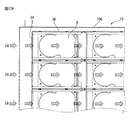
そのため、図1Aに示す情報処理装置であるサーバ搭載ラック50のように、ハードディスクドライブの保守・増設作業を容易に行なうために、通常ハードディスクドライブはレール及びイジェクタを一体化したユニット構造となっている。そして、サーバ搭載ラック50の前面側からハードディスクドライブを着脱する構造となっているものが一般的である。図1Aに示されるサーバ搭載ラック50では、複数のハードディスクドライブを搭載するラックマウントサーバ装置10が何段にも渡って積み重ねられている。そして、ハードディスクドライブ1の交換時には図1Bに示すように、ハードディスクドライブ1がサーバ搭載ラック50から引き出されたラックマウントサーバ装置10から取り出される。
Therefore, as in the
ラックマウントサーバ装置10の前面と背面はアクセスが容易なエリアAEであり、側面はアクセスが困難なエリアADである。ラックマウントサーバ装置10には、複数のハードディスクドライブ1を縦横方向に並べて収容する前面シェルフ10Sがあり、その後方にファン2、CPU3,メモリ4や拡張PCIボード5等が配置されている。ハードディスクドライブ1の側面には固定/挿抜用フレーム1Fが設けられており、この固定/挿抜用フレーム1Fを利用してハードディスクドライブ1は前面シェルフ10Sに収容される。
The front and back surfaces of the rack
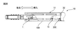
図2Aは、図1Bに示したラックマウントサーバ装置10のハードディスク搭載部である前面シェルフ10Sから1つのハードディスクドライブ1を抜き出す様子を示すものであり、図2Bは図2Aを側面から見た状態を示している。ハードディスクドライブ1の前面には着脱用部材1Uが設けられており、ハードディスクドライブ1をラックマウントサーバ装置10の前面シェルフ10Sから取り出す際には着脱用部材1Uを使用する。前面シェルフ10Sの壁面にはハードディスクドライブ1を取り付けるためのガイド11があり、ハードディスクドライブ1はガイド11に沿って接続/抜去が可能である。
FIG. 2A shows a state in which one
着脱用部材1Uを使用してハードディスクドライブ1を前面シェルフ10Sから引き出すと、前面シェルフ10Sの背面側に設けられたバックプレーン(回路基板)33にある接続コネクタ33Cとハードディスクドライブ1のコネクタ1Cとの接続が外れる。このように、ハードディスクドライブ1を前面シェルフ10Sから取り出す際に使用する着脱用部材1Uについては、類似の構成が特許文献1に開示されている。
When the
一方、今後も更なるデータ容量の増加が予想され、より大容量のハードディスクドライブを搭載した装置が必要となる。ところが、図1Bに示したようなハードディスクドライブ1を前面シェルフ10Sにしか搭載しないラックマウントサーバ装置10は、装置前面にある前面シェルフ10Sのスペースが、装置全体のサイズに比べて小さい。このため、どうしてもラックマウントサーバ装置10に搭載できるハードディスクドライブの台数が限られてくる。
On the other hand, the data capacity is expected to increase further in the future, and a device equipped with a larger capacity hard disk drive is required. However, in the rack
そのため、ハードディスクドライブの搭載密度を上げるには、ラックマウントサーバ装置10の前方のみではなく、ラックマウントサーバ装置10の中央部にもハードディスクドライブ1を搭載することが考えられる。図3Aは前面シェルフ10Sの後方のラックマウントサーバ装置10の中央部にハードディスクドライブ1を搭載した例を示すものである。
Therefore, in order to increase the mounting density of the hard disk drives, it is conceivable that the
このように、ラックマウントサーバ装置10の中央部にもハードディスクドライブ1を搭載した場合、保守・増設作業時には、図3Bに示すように、ハードディスクドライブ1を水平方向に移動してコネクタの抜去をしてから上方へ取り外す必要がある。逆に、ハードディスクドライブ1の取付け時には、ハードディスクドライブ1を上方から挿入してから水平方向に移動してコネクタの接続を行なう必要がある。
As described above, when the
その結果、保守・増設時の作業性を維持したままハードディスクドライブ1を取り出す場合には、前述の着脱用部材1U等でハードディスクドライブ1の接続を解除した後、ハードディスクドライブ1をガイド11より前方に引き出し切った後に上方へ取り出すことになる。このため、ラックマウントサーバ装置10の中央部に、ハードディスクドライブ1の増設・保守作業エリアMA(作業スペース)を確保しなければならず、ハードディスクドライブ1の実装密度が低下してしまうという問題がある。
As a result, when the
そこで、図4A、図4Bに示すように、ハードディスクドライブ1を取付金具13とネジ15で基板17上のブラケット14に固定し、ハードディスクドライブ1とラックマウントサーバ装置10との接続をケーブル12で行う構造が考えられた。この構造では、ハードディスクドライブ1を水平方向に移動させず、ケーブルコネクタ12Cをハードディスクドライブ1のコネクタ1Cから外せば、ハードディスクドライブ1を開口部16から上方へ直接引き出すことができ、増設・保守作業エリアMAを小さくできる。
Therefore, as shown in FIGS. 4A and 4B, the
しかしながら、ケーブルを使用する接続構造の場合、ハードディスクドライブの実装密度は改善できるが、保守・増設時の作業性が著しく低下してしまうという課題がある。更に、装置稼動状態での作業の場合は通電状態での作業となる為、安全面や機能的な保護等が必要となり、余分な機構が必要となる事から、結局、実装密度の低下を招き、さらにコストアップの要因ともなる。 However, in the case of a connection structure using a cable, the mounting density of hard disk drives can be improved, but there is a problem that workability at the time of maintenance / addition is significantly reduced. Furthermore, since the work is performed while the device is in operation, the work must be energized, so safety and functional protection are required, and an extra mechanism is required, resulting in a decrease in mounting density. Furthermore, it becomes a factor of cost increase.
ところで、図4Aに示した構造をとった場合、ハードディスクドライブ1の周囲に増設・保守作業エリアMAが確保でき、ハードディスクドライブ1側及び筐体10A側に着脱及び固定用の機構部品(取付金具13、ブラケット14等)が配置される。一方、ハードディスクドライブ1は発熱する為、冷却風CAを流して冷却する必要がある。しかし、増設・保守作業エリアMAが装置中央部にあると、図5A、図5Bに示すように、冷却風CAがその空間に流れてしまい、ハードディスクドライブ1の内部が冷却され難いという課題がある。又、着脱用の取付金具13、ブラケット14が障害物となり、ハードディスクドライブ1に冷却風CAが当たりづらくなる事による冷却性能の低下や、冷却風CAを正しく流す為の整流用機構を設ける為に、さらなる部品追加が必要となり、コストアップの要因となる。
4A, an expansion / maintenance work area MA can be secured around the
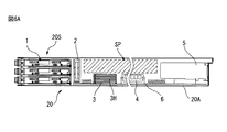
また、図6Aに示すようなサイズのラックマウントサーバ装置20では、前面シェルフ20Sに複数のハードディスクドライブ1が積み重ねられ、筐体20Aの中央部にマザーボード6が設けられている。そして、マザーボード6の上にはヒートシンク3Hを備えたCPU3、メモリ4、拡張PCIボード5等が実装されており、ヒートシンク3Hを備えたCPU3やメモリ4等の背の低い部品の上方には部品のない未使用エリアSPがあった。このような場合、図6Bに示すように、未使用エリアSPに冷却ダクト7を設けて冷却風CAが効率良くヒートシンク3Hを備えたCPU3やメモリ4を冷却することが行われるが、未使用エリアSPが無駄なスペースとなっていた。
Further, in the rack
1つの側面では、本出願は、装置筐体の上方向よりハードディスクドライブの挿抜作業な可能なハードディスクドライブ着脱機構を設けたハードディスクドライブ搭載装置の提供を目的とする。また、このようなハードディスクドライブ搭載装置を複数積み重ねて形成される情報処理装置の提供も目的とする。 In one aspect, an object of the present application is to provide a hard disk drive mounting device provided with a hard disk drive attaching / detaching mechanism capable of inserting and removing a hard disk drive from above the device housing. It is another object of the present invention to provide an information processing apparatus formed by stacking a plurality of such hard disk drive mounting devices.
実施形態の一観点によれば、両側面にガイドピンが突設されたガイドピン付のハードディスクドライブが交換可能に搭載されるラックマウント型のハードディスクドライブ搭載装置であって、ハードディスクドライブ搭載装置の筐体内のハードディスクドライブの搭載エリアに、1つのハードディスクドライブの搭載部分毎に、搭載部分に対してハードディスクドライブを独立に着脱できるハードディスクドライブ着脱機構が設けられており、ハードディスクドライブ着脱機構が、ガイドピンを受け入れるガイド溝を備えた固定レールと、固定レールに対して移動可能に重なり、ガイド溝に入った前記ガイドピンをガイドピン駆動溝によって移動させる移動レールとを備え、ガイド溝にガイドピンが挿入された時に、固定レールの一端側に移動レールを移動させると搭載部分にハードディスクドライブが搭載され、搭載部分にハードディスクドライブが搭載された状態で固定レールの他端側に移動レールを移動させると、搭載部分からハードディスクドライブが取り出せる状態になるハードディスクドライブ搭載装置が提供される。 According to one aspect of the embodiment, there is provided a rack mount type hard disk drive mounting device in which hard disk drives with guide pins protruding from both sides are mounted in a replaceable manner. A hard disk drive mounting / removal mechanism is provided in the internal hard disk drive mounting area for each hard disk drive mounting part, and the hard disk drive mounting / removal mechanism can be attached to / detached from the mounting part independently. A fixed rail having a guide groove to be received, and a moving rail that is movably overlapped with the fixed rail and moves the guide pin that has entered the guide groove by a guide pin driving groove, and the guide pin is inserted into the guide groove Move to one end of the fixed rail. When the rail is moved, the hard disk drive is mounted on the mounting part. When the moving rail is moved to the other end of the fixed rail while the hard disk drive is mounted on the mounting part, the hard disk drive is ready to be removed from the mounting part. A drive-mounted device is provided.
また、実施形態の他の観点によれば、両側面にガイドピンが突設されたガイドピン付のハードディスクドライブ及び前面に着脱用部材を有するガイドピン無しのハードディスクドライブが交換可能に搭載されるラックマウント型のハードディスクドライブ搭載装置であって、ハードディスクドライブ搭載装置の筐体内に、ガイドピン付のハードディスクドライブを搭載する第1の搭載エリアと、ガイドピン無しのハードディスクドライブを搭載する第2の搭載エリアとを備え、第2の搭載エリアが筐体の前面側に設けられ、第1の搭載エリアが第2の搭載エリアよりも背面側に設けられ、第1の搭載エリアには、1つのガイドピン付のハードディスクドライブの搭載部分毎に、搭載部分に対してガイドピン付のハードディスクドライブを独立に着脱できるハードディスクドライブ着脱機構が設けられ、ハードディスクドライブ着脱機構が、ガイドピンを受け入れるガイド溝を備えた固定レールと、固定レールに対して移動可能に重なり、ガイド溝に入ったガイドピンをガイドピン駆動溝によって移動させる移動レールとを備え、ガイド溝にガイドピンが挿入された時に固定レールの一端側に移動レールを移動させると、搭載部分にガイドピン付のハードディスクドライブが搭載され、搭載部分にハードディスクドライブが搭載された状態で固定レールの他端側に移動レールを移動させると、搭載部分からガイドピン付のハードディスクドライブが取り出せる状態になるハードディスクドライブ搭載装置が提供される。 Further, according to another aspect of the embodiment, a rack in which a hard disk drive with guide pins having guide pins protruding on both side surfaces and a hard disk drive without guide pins having a detachable member on the front surface are mounted in a replaceable manner. A mount type hard disk drive mounting device, a first mounting area for mounting a hard disk drive with guide pins and a second mounting area for mounting a hard disk drive without guide pins in the housing of the hard disk drive mounting device. And the second mounting area is provided on the front side of the housing, the first mounting area is provided on the back side of the second mounting area, and one guide pin is provided in the first mounting area. A hard disk drive with a guide pin is independent for each mounted part of the attached hard disk drive. A removable hard disk drive attachment / detachment mechanism is provided, and the hard disk drive attachment / detachment mechanism overlaps the fixed rail with a guide groove for receiving the guide pin and movably overlaps with the fixed rail, and the guide pin in the guide groove is driven by the guide pin. When the guide rail is moved to one end of the fixed rail when the guide pin is inserted into the guide groove, a hard disk drive with a guide pin is mounted on the mounting part, and a hard disk is mounted on the mounting part. When the moving rail is moved to the other end side of the fixed rail in a state where the drive is mounted, a hard disk drive mounting device is provided in which the hard disk drive with guide pins can be taken out from the mounting portion.
以下、添付図面を用いて本出願に係るハードディスクドライブ搭載装置の実施の形態を、具体的な実施例に基づいて詳細に説明する。なお、以下に説明する実施例ではハードディスクドライブ(HDD)を説明するが、ハードディスクドライブと同様の形状を持つ装置であれば、本機構は適用可能である。例えば、光ディスク装置やシリコンディスクと呼ばれるSSD(ソリッドステートドライブ:固体型ドライブ)にも適用が可能である。 Embodiments of a hard disk drive mounting device according to the present application will be described below in detail based on specific examples with reference to the accompanying drawings. In the embodiment described below, a hard disk drive (HDD) will be described. However, this mechanism can be applied to any apparatus having the same shape as the hard disk drive. For example, the present invention can also be applied to an SSD (Solid State Drive: Solid State Drive) called an optical disk device or a silicon disk.
図7Aは本出願のハードディスクドライブ搭載装置に搭載するハードディスクドライブ8の構造を示すものである。本出願のハードディスクドライブ搭載装置に搭載するハードディスクドライブ8は、両側面にガイドピン8Pが2本ずつ突設され、両側面に隣接する一方の端部にコネクタ8Cが設けられたものである。
FIG. 7A shows the structure of the
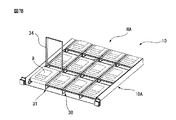
図7Bは、ラックマウントサーバ装置から引き出されたハードディスクドライブ搭載装置である本出願の第1の実施例のラックマウントサーバ装置10から、1つのハードディスク8を取り出す様子を示すものである。第1の実施例のラックマウントサーバ装置10の筐体10Aは1Uサイズの高さを備えており、高さ方向に1つのハードディスクドライブを収容することができる。ラックマウントサーバ装置10にはハードディスクドライブの搭載エリアHAがあり、この搭載エリアHAに複数のハードディスクドライブ8が縦横方向に並んで搭載されている。第1の実施例のラックマウントサーバ装置10には、ハードディスクドライブ着脱機構30が、ラックマウントサーバ装置10に搭載するハードディスクドライブ8の数と同数だけ設けられている。ハードディスクドライブ着脱機構30には操作レバー34があり、この操作レバー34を持ち上げるとハードディスクドライブ8が搭載エリアHAから取り出される。
FIG. 7B shows a state in which one
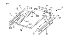
図8Aは、図7Bに示した本出願の第1の実施例のラックマウントサーバ装置10に設けられている1つのハードディスクドライブ着脱機構30の構造を示すものである。ハードディスクドライブ着脱機構30には、2枚の固定レール31と移動レール32、回路基板33及び操作レバー34を備えている。2枚の固定レール31は平行に配置されており、回路基板33は、固定レール31の各個の一方の端部の間に設けられており、ハードディスクドライブ8に接続する接続コネクタ33Cを備えている。
FIG. 8A shows the structure of one hard disk drive attaching /
固定レール31の両側には、移動レール32を摺動させるためのスライドガイド31Gが設けられている。よって、移動レール32は、固定レール31のスライドガイド31Gで挟まれた空間内を、回路基板33に対して離れる方向或いは近づく方向に摺動可能である。移動レール32は、固定レール31の両側に設けることができる。2枚の固定レール31には夫々ハードディスクドライブ8にあるガイドピン8Pの位置に対応するガイド溝35がある。ガイド溝35は、ハードディスクドライブ8の搭載時にガイドピン8Pを受け入れる垂直溝35Vと、垂直溝35V内のガイドピン8Pを回路基板33側に移動させる水平溝35Hとを備えている。
On both sides of the fixed
垂直溝35Vの深さは、ガイドピン8Pが垂直溝35Vの底部に達した時に、ハードディスクドライブ8に設けられたコネクタ8Cが、回路基板33に設けられた接続コネクタ33Cと水平位置において一致する深さである。また、水平溝35Hの長さは、ガイドピン8Pが水平溝35Hの最奥部まで移動した時に、ハードディスクドライブ8に設けられたコネクタ8Cが回路基板33に設けられた接続コネクタ33Cに接続される長さである。
The depth of the
一方、2枚の移動レール32には夫々、ガイドピン駆動溝36がガイド溝35と同じ間隔で設けられている。ガイドピン駆動溝36は、回路基板33に近い側に斜面部36S、遠い側に垂直部36Vを備えている。移動レール32が固定レール31に設けられたスライドガイド31Gの間に摺動可能に嵌め込まれると、移動レール32の摺動時に、斜面部36S又は垂直部36Vの何れかがガイド溝35に重なる。
On the other hand, each of the two moving
また、ハードディスクドライブ着脱機構30には、固定レール31に対して移動レール32を移動させることができる移動レール駆動部材である操作レバー34が設けられている。操作レバー34は、2本の長棒34A、2本の短棒34B及び1本の連絡棒34Cを備えた略U字状をしている。長棒34Aは固定レール31と同程度の長さを備え、短棒34Bは長棒34Aに対して回路基板33側の端部に所定角度で接続され、連絡棒34Cは2本の長棒34Aの他方の端部を接続している。長棒34Aと短棒34Bの接続部には軸孔34Hがあり、長棒34Aと短棒34Bの接続部は、軸孔34Hに挿通されるピン37によって固定レール31の回路基板33側の端部に回転可能に接続される。また、短棒34Bの自由端部には長孔34Lがあり、移動レール32の回路基板33側の端部に設けられた軸孔32Hに挿通されたピン38がこの長孔34Lに挿入される。
Further, the hard disk drive attaching /
操作レバー34がこのように固定レール31と移動レール32に連結された状態では、操作レバー34の長棒34Aを固定レール31に対して回転させると、短棒34Bによって移動レール32が固定レール31に対して移動する。そして、ハードディスクドライブ8がハードディスクドライブ着脱機構30の中に搭載された状態では、連絡棒34Cが固定レール31の他方の端部の位置に移動して、操作レバー34が閉じた状態となる。図8Bは、図7Bに示した本出願の第1の実施例のラックマウントサーバ装置10に設けられたハードディスクドライブ着脱機構30の中にハードディスクドライブ8が無い状態を示すものであり、操作レバー34の移動範囲を示している。
In a state where the
図9Aは、ハードディスクドライブ8に突設されたガイドピン8Pと、ラックマウントサーバ装置10に設けられたハードディスクドライブ着脱機構30の固定レール31と移動レール32との関係を説明するものである。移動レール32は固定レール31に設けられたスライドガイド31Gの間に挿入される。そして、ハードディスクドライブ8をハードディスクドライブ着脱機構30に取り付ける場合は、ガイドピン8Pが固定レール31に設けられたガイド溝35に挿入される。
FIG. 9A illustrates the relationship between the
ここで、ハードディスクドライブ着脱機構30にハードディスクドライブ8を搭載する時のハードディスクドライブ着脱機構30の動作を、図9Bと、図10Aから図10Fを用いて説明する。ハードディスクドライブ8がハードディスクドライブ着脱機構30に搭載されていない状態では、図10A及び図9Bの一番上の図に示すように、操作レバー34は固定レール31から立ち上った状態(開いた状態)にある。そして、移動レール32は回路基板33から最も遠い位置に移動した位置にある。この状態では、ガイドピン駆動溝36の斜面部36Sは、ガイド溝35の垂直溝35Vに重なっている。
Here, the operation of the hard disk drive attaching /
ハードディスクドライブ着脱機構30の中にハードディスクドライブ8が搭載され、ガイドピン8Pが垂直溝35V内に挿入されると、ガイドピン8Pは、図10A,図10Bに示すように、垂直溝35V内でガイドピン駆動溝36の斜面部36Sに当接して止まる。図10Bは図10AのA−A線における断面を示している。この状態で操作レバー34を倒して回転させ、移動レール32を回路基板33側に移動させると、図10Aに示す斜面部36Sが垂直溝35Vに重なった状態では、斜面部36Sがガイドピン8Pを保持しながら垂直溝35V内で降下させる。
When the
操作レバー34を更に回転させるとガイドピン8Pが垂直溝35Vの最下部まで移動し、図10Cに示す状態となる。この状態は、図9Bの2番目の図にも示すように、斜面部36Sが水平溝35Hに重なった状態である。図10Cに示す状態から操作レバー34を更に回転させると、図9Bの3番目の図に示すように、ガイドピン駆動溝36の垂直部36Vが垂直溝35Vの中に移動する。この後は、図10Dに示すようにガイドピン駆動溝36の垂直部36Vがガイドピン8Pを押してガイド溝35の水平溝35H内で回路基板33側に移動させる。そして、ガイドピン8Pがガイド溝35の水平溝35H内で回路基板33側に移動する過程で、ハードディスクドライブ8のコネクタ8Cが回路基板33にある接続コネクタ33Cに結合されていく。
When the
操作レバー34が固定レール31に重なる位置まで回転させると、図9Bの最も下の図に示すように、ガイドピン駆動溝36の斜面部36Sが水平溝35Hに重ならなくなる。そしてこの状態では、ガイドピン8Pがガイドピン駆動溝36の垂直部36Vとガイド溝35の水平溝35Hの端部との間に挟まれて固定される。この状態では、ハードディスクドライブ8のコネクタ8Cが回路基板33にある接続コネクタ33Cに結合している。図10Fは図10EのB−B線における状態を示すものである。
When the
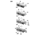
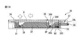
次に、ハードディスクドライブ着脱機構30からハードディスクドライブ8を取り外す時のハードディスクドライブ着脱機構30の動作を、図9Cと、図11Aから図11Fを用いて説明する。図11Aの状態は、図10Eに示した状態と同じである。この状態から操作レバー34を引き上げると、図9Cの最も下の図に示すように、ガイドピン駆動溝36の斜面部36Sが、ガイドピン8Pに当接してこれを押す。
Next, the operation of the hard disk drive attaching /
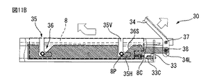
操作レバー34を引き上げると、図11Bに示すようにガイドピン8Pがガイドピン駆動溝36の斜面部36Sに押されてガイド溝35の水平溝35H内を移動し、やがて図9Cの下から2番目の図に示すガイド溝35の垂直溝35Vに当接して水平移動が止まる。ガイドピン8Pがガイド溝35の水平溝35H内を移動する過程で、ハードディスクドライブ8のコネクタ8Cが回路基板33の接続コネクタ33Cから抜去される。操作レバー34を更に引き上げると、ガイドピン8Pは図9Cの上から2番目の図に示す斜面部36Sに押されて今度はガイド溝35の垂直溝35Vの中を上昇する。この状態が図11Cに示される。
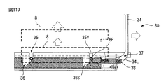
When the
操作レバー34が固定レール31に対して垂直の状態まで引き上げられると、操作レバー34はこれ以上回転できなくなり、ガイドピン8Pは図11Dに示す位置までガイド溝35の垂直溝35Vの中を上昇する。この時、ガイドピン8Pは図9Cの1番上の図に示すガイドピン駆動溝36の斜面部36Sに保持されている。ガイドピン8Pが図11Dに示す位置まで上昇した状態では、ハードディスクドライブ8の上部がハードディスクドライブ着脱機構30から露出している。そこで、露出部を掴んでハードディスクドライブ8を上に引き上げることにより、ハードディスクドライブ8をハードディスクドライブ着脱機構30から取り外すことができる。
When the
図12Aは、図7Bに示した本出願のハードディスクドライブ着脱機構30を備えた第1の実施例のラックマウントサーバ装置10における筐体10A内を流れる冷却風CAの流れを示すものである。また、図12Bは図12Aに示したラックマウントサーバ装置10の筐体10Aにおける冷却風CAの流れを側面側から見た側面図である。ハードディスクドライブ着脱機構30を使用することにより、ハードディスクドライブ8の間に余分なスペースが無くなる。又、ハードディスクドライブ8自体には冷却風CAの流れを妨げるような機構が不要なため、冷却風CAがハードディスクドライブ8の表面に多く流れ込み、発熱部分を効率よく冷却する事が可能となる。
FIG. 12A shows the flow of the cooling air CA flowing in the
図13Aは、図7Bに示したラックマウントサーバ装置10が情報処理装置であるサーバ搭載ラック50から引き出された状態を示すものである。ラックマウントサーバ装置10の筐体10Aの側面には、サーバ搭載ラック50よりラックマウントサーバ装置10を引き出す為のスライドレール51が設けられている。ラックマウントサーバ装置10の内部には、図13Bに示すように、サーバの主要機能を構成するマザーボード6や電源ユニット9、冷却ファン2等が搭載されている。また、ラックマウントサーバ装置10の内部には、ハードディスクドライブ8を着脱可能に搭載するための、固定レール31、移動レール32及び操作レバー34を備えるハードディスクドライブ着脱機構30が設けられている。
FIG. 13A shows a state in which the rack
ラックマウントサーバ装置10のハードディスクドライブ着脱機構30には、図13Cに示すように、ガイドピン8Pが両側面に設けられたハードディスク8を搭載する。また、ハードディスク8の搭載部の上部には、装置稼動状態でもハードディスクドライブ8の部分のみを部分的に開閉可能な保守用カバー18を設ける。なお、図13Bには、図13A、図13Cに示した保守用カバー18の図示が省略されている。
As shown in FIG. 13C, the
本出願のように、ハードディスクドライブ着脱機構を使用してハードディスクドライブを搭載する事により、ハードディスクドライブ自体に挿抜用の機構を設ける必要が無く、また作業スペースを最小限に抑えることができる為、ハードディスクドライブが容易に着脱可能となる。また、ハードディスクドライブの実装密度の向上及び部品コストを低減する事が可能となる。更に、実装密度が向上することにより、冷却経路が最適化され、冷却性能を向上させることが可能となる。 By mounting the hard disk drive using the hard disk drive attaching / detaching mechanism as in the present application, it is not necessary to provide a mechanism for insertion / extraction in the hard disk drive itself, and the work space can be minimized, so that the hard disk The drive can be easily attached and detached. In addition, it is possible to improve the mounting density of the hard disk drive and reduce the component cost. Furthermore, by improving the mounting density, the cooling path is optimized and the cooling performance can be improved.
なお、第1の実施例では、ハードディスクドライブ着脱機構30を搭載したラックマウントサーバ装置10について説明したが、ハードディスクドライブ着脱機構30は、CPU等を搭載しないストレージ装置にも搭載することが可能である。
In the first embodiment, the rack
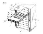
図14Aは、サーバ搭載ラック50に搭載された本出願の第2の実施例のラックマウントサーバ装置20が、筐体20Aに取り付けられたスライドレール51を使用してサーバ搭載ラック50から引き出された状態を示すものである。第1の実施例のラックマウントサーバ装置10は、高さが最小限のサイズ(1Uサイズ)であった。これに対し、第2の実施例のラックマウントサーバ装置20は高さがこれより高いサイズ(例えば2Uサイズ)を有する点が第1の実施例のラックマウントサーバ装置10と相違する点である。第2の実施例のラックマウントサーバ装置20は2Uサイズの高さを有するので、前面シェルフ20Sには筐体20Aの高さ方向に3段にハードディスクドライブ1が積み重ねられている。ラックマウントサーバ装置20の前面シェルフ20Sに搭載されるハードディスクドライブ1は、前面シェルフ20Sに対して前方(正面側)から着脱できるので、ハードディスクドライブ1の両側面にはガイドピンは設けられていない。
In FIG. 14A, the rack
図14Bは、図14Aに示したラックマウントサーバ装置20を側面から見たものである。ラックマウントサーバ装置20内には、前面から着脱作業可能なハードディスクドライブ1を搭載する前面シェルフ20Sがある。前面シェルフ20Sの後方には、サーバの主要機能を構成するマザーボード6、冷却ファン2、ヒートシンク3Hを備えたCPU3,メモリ4及び拡張用のPCIボード(図示せず)等が搭載されている。2Uサイズのラックマントサーバ装置20では、前述のように、ヒートシンク3Hを備えたCPU3やメモリ4の背が低いので、マザーボード6の上部に未使用エリアがある。
14B is a side view of the rack
そこで、第2の実施例では、第1の実施例のラックマントサーバ装置10に設けたハードディスクドライブ着脱機構30を、筐体20Aにスペーサ29等を用いてマザーボード6に干渉しないように取り付ける。ハードディスクドライブ着脱機構30には、ガイドピン8Pを備えるハードディスクドライブ8を搭載し、ハードディスクドライブ着脱機構30の上部には装置稼動状態で取り外し可能な上部カバー28を設ける。
Therefore, in the second embodiment, the hard disk drive attaching /
通常の2Uサイズのラックマウントサーバ装置では、マザーボードの主要機能が搭載されている部分と、拡張PCIボードや冷却ファン、ハードディスク等が搭載される部分では、搭載部品の高さの違いにより、CPUやメモリの上部に未使用エリアが発生していた。一方、本出願の第2の実施例のラックマウントサーバ装置20では、未使用エリアにハードディスクドライブ着脱機構30を設けてハードディスクドライブ8を搭載し、ハードディスクドライブ8の搭載数を増やしている。そして、ハードディスクドライブ着脱機構30は主に、固定レール31、移動レール32及び操作レバー34で構成され、ハードディスクドライブ8を取り除けば、底面部分が開いている為、マザーボード6上のCPU3やメモリ4等の保守・増設作業性を極力損なわない。このように、第2の実施例のラックマウントサーバ装置20では、本来デッドスペースとなる所に、ハードディスクドライブ8を搭載できるため、未使用エリアを有効活用する事ができ、高密度実装が可能となる。
In a normal 2U size rack mount server device, the CPU and other parts of the part where the main functions of the motherboard are installed and the part where the expansion PCI boards, cooling fans, hard disks, etc. There was an unused area at the top of the memory. On the other hand, in the rack
図15Aは、サーバ搭載ラックに搭載可能な第2の実施例の変形実施例の2Uサイズのラックマウントサーバ装置20を示すものである。また、図15Bは、図15Aに示したラックマウントサーバ装置20の内部構造及び内部を流れる冷却風CAの状態を説明するものである。本変形実施例では、前面から着脱可能なハードディスクドライブ1を搭載している前面シェルフ20Sの一部(下部)に、マザーボード6を配置し、その上のCPU3を実装している。そして、ラックマウントサーバ装置20の前面には吸気口21を設けて冷却風CAがより多くCPU3に当たるようにしている。
FIG. 15A shows a 2U-sized rack
一方、CPU3をラックマウントサーバ装置20の前面に実装することにより、前面シェルフ20Sに搭載できなくなったハードディスクドライブ1については、これと同様の記憶容量を持つガイドピン8P付のハードディスクドライブ8に変更する。そして、変更したハードディスクドライブ8をハードディスクドライブ着脱機構30を用いて第2実施例と同様に、マザーボード6の上部空間にスペーサ29を用いて搭載する。ハードディスクドライブ着脱機構30の下方のマザーボード6にはメモリ4等を実装することができる。
On the other hand, by mounting the
通常、ハードディスクドライブを大量にラックマウントサーバ装置に搭載すると、ハードディスクドライブは吸気口のある装置前面部に配置されてしまう。このため、ハードディスクドライブが障害物となり、冷却風のラックマウントサーバ装置内への流入量が下がってしまい、サーバ用等の発熱量の高いCPUを冷却する場合の冷却風による冷却効率が低下していた。 Normally, when a large number of hard disk drives are mounted on a rack mount server device, the hard disk drives are arranged on the front surface of the device having an air inlet. For this reason, the hard disk drive becomes an obstacle, the amount of cooling air flowing into the rack mount server device decreases, and the cooling efficiency due to the cooling air when cooling a CPU with a high calorific value for servers or the like is reduced. It was.
しかし、ラックマウントサーバ装置の前面にあったハードディスクドライブを装置内部に搭載する事により、ハードディスクドライブの搭載台数は維持したまま、冷却風による冷却効率が最も良い場所に、最も冷却する必要のあるCPUを配置する事が可能となる。これにより、CPUの冷却効率を大幅に改善する事ができ、また冷却ファンの能力を抑える事が可能となる為、電力を削減する事も可能となる。 However, by installing the hard disk drive that was on the front of the rack mount server device inside the device, the CPU that needs to be cooled most in a place where the cooling efficiency by cooling air is the best while maintaining the number of hard disk drives mounted Can be arranged. As a result, the cooling efficiency of the CPU can be greatly improved, and the capacity of the cooling fan can be suppressed, so that the power can be reduced.
図16Aは本出願の第1の実施例のラックマウントサーバ装置10に搭載される別の構造のハードディスクドライブ着脱機構30Aを示すものである。図8A,図8Bに示した構造のハードディスクドライブ着脱機構30では、操作レバー34の回転基部が回路基板33側にあり、連絡棒34Cが回路基板33から遠い側の固定レール31の端部側にあった。一方、図16Aに示すハードディスクドライブ着脱機構30Aでは、操作レバー34の回転基部が回路基板33から遠い側にあり、連絡棒34Cが回路基板33側の固定レール31の端部側にある。ハードディスクドライブ着脱機構30Aにおける固定レール31及び移動レール32の構造は、ハードディスクドライブ着脱機構30における固定レール31及び移動レール32の構造と同じである。
FIG. 16A shows a hard disk drive attaching /
したがって、ハードディスクドライブ着脱機構30Aの動作は、操作レバー34の引き上げ方向が異なるだけで、その他の動作はハードディスクドライブ着脱機構30の動作と全く同じである。そして、図16Aの状態が図11Aの状態に対応し、図16Bの状態が図11Bの状態に対応し、図16Cの状態が図11Dの状態に対応する。よって、同じ構成部材には同じ符号を付してその動作説明を省略する。
Therefore, the operation of the hard disk drive attaching /
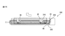
図17Aは、本出願のラックマウントサーバ装置に設けられる更に別の構造を備えたハードディスクドライブ着脱機構30Cを示すものである。ハードディスクドライブ着脱機構30Cには操作レバーはなく、移動レール32の回路基板33から遠い側の端部に、両端部を接続する操作ロッド39が設けられている。ハードディスクドライブ着脱機構30,30Aでは、操作レバー34を固定レール31に対して回転させることによって移動レール32を移動させていた。一方、本実施例のハードディスクドライブ着脱機構30Cでは、操作ロッド39を外部から引いたり押したりすることによって移動レール32を移動させている。このため、移動レール32の回路基板33側の端部には、移動レール32の最大引出し位置を定めるストッパ32Sが設けられている。移動レール32はこのストッパ32Sが固定レール31に設けられたスライドガイド31Gの端部に当接する位置まで引き出すことができる。
FIG. 17A shows a hard disk drive attaching / detaching mechanism 30C having still another structure provided in the rack mount server device of the present application. The hard disk drive attaching / detaching mechanism 30C has no operating lever, and an operating
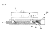
図17Bは、ハードディスクドライブ着脱機構30Cの操作ロッド39に指Fを掛けて移動レール32を引き出す状態を示すものであり、ハードディスクドライブ8、固定レール31及び移動レール32の状態は図11Aに示す状態と同じである。図17Cは、図17Bの状態から操作ロッド39が更に引っ張られた状態を示しており、ハードディスクドライブ8、固定レール31及び移動レール32の状態は図11Bに示す状態と同じである。図17Dは、図17Cの状態から操作ロッド39が、最大引出し位置まで引き出された状態を示しており、ハードディスクドライブ8、固定レール31及び移動レール32の状態は図11Dに示す状態と同じである。ハードディスクドライブ着脱機構において、固定レールに対して移動レールを移動させる部材は、操作レバーや操作ロッドに限定されるものではない。
FIG. 17B shows a state where the finger F is put on the
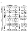
図18は、サーバ搭載ラックに搭載された本出願のハードディスクドライブ着脱機構を備えたラックマウントサーバ装置から、1つのハードディスクドライブを活性交換する場合の交換手順を、比較技術における交換手順と比較して示すフロー図である。図18にはハードディスクドライブはHDDと記載してある。 FIG. 18 shows a comparison between the replacement procedure in the case where one hard disk drive is actively replaced from the rack mount server device equipped with the hard disk drive attaching / detaching mechanism of the present application mounted in the server-mounted rack in comparison with the replacement procedure in the comparative technique. FIG. In FIG. 18, the hard disk drive is described as HDD.
通常、ラックマウントサーバ装置の内部にハードディスクドライブを搭載した場合には、ハードディスクドライブが通電状態の時にハードディスクドライブに接触して作業する必要がある。しかし、本出願のハードディスクドライブ着脱機構を備えたラックマウントサーバ装置では、ハードディスクドライブに直接触れる事無く、電気的な接続及び解除ができる。このため、危険防止や誤動作防止の為のハードディスク単体を保護するカバーやその他の機構部品が不要となる。これらにより、実装密度の向上や不要部品削減によるコスト低減、さらには冷却的にも不要な部品やスペースが無くなる事で、冷却経路が単純化され冷却対象のハードディスクドライブを効率的に冷却可能となる事から、冷却性能を向上させる事ができる。 Normally, when a hard disk drive is mounted inside the rack mount server device, it is necessary to work by contacting the hard disk drive when the hard disk drive is energized. However, the rack mount server device having the hard disk drive attaching / detaching mechanism of the present application can be electrically connected and disconnected without directly touching the hard disk drive. For this reason, a cover for protecting the hard disk alone and other mechanical parts for preventing danger and malfunction are not required. As a result, the cost is reduced by improving the mounting density and reducing unnecessary parts. Furthermore, by eliminating unnecessary parts and space for cooling, the cooling path is simplified and the hard disk drive to be cooled can be efficiently cooled. Therefore, the cooling performance can be improved.
以上、本出願を特にその好ましい実施の形態を参照して詳細に説明した。本出願の容易な理解のために、本出願の具体的な形態を以下に付記する。 The present application has been described in detail with particular reference to preferred embodiments thereof. For easy understanding of the present application, specific forms of the present application are appended below.
(付記1) 両側面にガイドピンが突設されたガイドピン付のハードディスクドライブが交換可能に搭載されるハードディスクドライブ搭載装置であって、
前記ハードディスクドライブ搭載装置の筐体内の前記ハードディスクドライブの搭載エリアに、1つの前記ハードディスクドライブの搭載部分毎に、前記搭載部分に対して前記ハードディスクドライブを独立に着脱できる機構が設けられており、
前記機構が、
前記ガイドピンを受け入れるガイド溝を備えた固定レールと、
該固定レールに対して隣接し、前記ガイド溝に入った前記ガイドピンを駆動溝によって移動させる移動レールとを備え、
前記ガイド溝に前記ガイドピンが挿入された時に前記固定レールの一端側に前記移動レールを移動させると、前記搭載部分に前記ハードディスクドライブが搭載され、前記搭載部分に前記ハードディスクドライブが搭載された状態で前記固定レールの他端側に前記移動レールを移動させると、前記搭載部分から前記ハードディスクドライブが取り出せる状態になるハードディスクドライブ搭載装置。
(付記2) 両側面にガイドピンが突設されたガイドピン付のハードディスクドライブ及び前面に着脱用部材を有するガイドピン無しのハードディスクドライブが、交換可能に搭載されるハードディスクドライブ搭載装置であって、
前記ハードディスクドライブ搭載装置の筐体内に、前記ガイドピン付のハードディスクドライブを搭載する第1の搭載エリアと、前記ガイドピン無しのハードディスクドライブを搭載する第2の搭載エリアとを備え、
前記第2の搭載エリアが前記筐体の前面側に設けられ、前記第1の搭載エリアが前記第2の搭載エリアよりも背面側に設けられ、
前記第1の搭載エリアには、前記ガイドピン付のハードディスクドライブの搭載部分毎に、前記搭載部分に対して前記ガイドピン付のハードディスクドライブを独立に着脱できる機構が設けられ、
前記機構が、
前記ガイドピンを受け入れるガイド溝を備えた固定レールと、
該固定レールに対して隣接し、前記ガイド溝に入った前記ガイドピンを駆動溝によって移動させる移動レールとを備え、
前記ガイド溝に前記ガイドピンが挿入された時に前記固定レールの一端側に前記移動レールを移動させると、前記搭載部分に前記ガイドピン付のハードディスクドライブが搭載され、前記搭載部分に前記ハードディスクドライブが搭載された状態で前記固定レールの他端側に前記移動レールを移動させると、前記搭載部分から前記ガイドピン付のハードディスクドライブが取り出せる状態になる付記1に記載のハードディスクドライブ搭載装置。
(付記3) 前記固定レールが平行に配置された2枚の固定レールであり、
前記固定レールの各個の一方の端部の間に、前記ガイドピン付のハードディスクドライブに接続する接続コネクタを備えた基板が設けられており、
前記移動レールは、前記固定レールの内側を、前記基板に対して離れる方向或いは近づく方向に摺動可能であり、
前記ガイド溝は、前記ハードディスクドライブの搭載時に前記ガイドピンを受け入れる垂直溝と、前記垂直溝内の前記ガイドピンを前記基板側に移動させる水平溝とを備えており、
前記駆動溝は、前記基板に近い側に斜面部、遠い側に垂直部を備え、前記移動レールの摺動時に、前記斜面部又は前記垂直部を前記ガイドピンに当接させて前記ガイドピンを前記ガイド溝内で移動させる付記1又は2に記載のハードディスクドライブ搭載装置。
(付記4) 前記移動レールに、外力の印加により前記移動レールを移動させる移動レール駆動部材が設けられている付記1から3の何れかに記載のハードディスクドライブ搭載装置。
(付記5) 前記垂直溝の深さは、前記ガイドピンが前記垂直溝の底部に達した時に、前記ハードディスクドライブに設けられたコネクタが前記基板に設けられた接続コネクタと水平位置において一致する深さであり、
前記水平溝の長さは、前記ガイドピンが前記水平溝の端部まで移動した時に、前記ハードディスクドライブに設けられたコネクタが前記基板に設けられた接続コネクタに接続される長さである付記1から4の何れかに記載のハードディスクドライブ搭載装置。
(Supplementary note 1) A hard disk drive mounting device in which a hard disk drive with guide pins projecting on both sides is mounted in a replaceable manner,
In the hard disk drive mounting area in the housing of the hard disk drive mounting device, for each mounting portion of the hard disk drive, there is provided a mechanism capable of independently attaching and detaching the hard disk drive to the mounting portion,
The mechanism is
A fixed rail having a guide groove for receiving the guide pin;
A moving rail that is adjacent to the fixed rail and moves the guide pin that has entered the guide groove by a drive groove;
When the guide rail is inserted into the guide groove and the moving rail is moved to one end of the fixed rail, the hard disk drive is mounted on the mounting portion, and the hard disk drive is mounted on the mounting portion. When the movable rail is moved to the other end side of the fixed rail, the hard disk drive mounting device is brought into a state where the hard disk drive can be taken out from the mounting portion.
(Supplementary note 2) A hard disk drive mounting apparatus in which a hard disk drive with guide pins projecting on both sides and a hard disk drive without guide pins having a detachable member on the front surface are mounted in a replaceable manner,
In the housing of the hard disk drive mounting device, a first mounting area for mounting the hard disk drive with the guide pin and a second mounting area for mounting the hard disk drive without the guide pin are provided.
The second mounting area is provided on the front side of the housing; the first mounting area is provided on the back side of the second mounting area;
In the first mounting area, for each mounting portion of the hard disk drive with the guide pin, a mechanism is provided that allows the hard disk drive with the guide pin to be independently attached to and detached from the mounting portion.
The mechanism is
A fixed rail having a guide groove for receiving the guide pin;
A moving rail that is adjacent to the fixed rail and moves the guide pin that has entered the guide groove by a drive groove;
When the moving rail is moved to one end side of the fixed rail when the guide pin is inserted into the guide groove, the hard disk drive with the guide pin is mounted on the mounting portion, and the hard disk drive is mounted on the mounting portion. The hard disk drive mounting device according to
(Appendix 3) The fixed rails are two fixed rails arranged in parallel,
Between one end of each of the fixed rails, a board having a connector for connecting to the hard disk drive with the guide pins is provided,
The moving rail is slidable in the direction away from or closer to the substrate on the inner side of the fixed rail,
The guide groove includes a vertical groove that receives the guide pin when the hard disk drive is mounted, and a horizontal groove that moves the guide pin in the vertical groove to the substrate side,
The drive groove includes a slope portion on the side closer to the substrate and a vertical portion on the far side, and the slide pin or the vertical portion is brought into contact with the guide pin when the moving rail slides. The hard disk drive mounting device according to
(Additional remark 4) The hard-disk drive mounting apparatus in any one of
(Supplementary Note 5) The depth of the vertical groove is such that when the guide pin reaches the bottom of the vertical groove, the connector provided on the hard disk drive matches the connecting connector provided on the substrate in a horizontal position. Is,
The length of the horizontal groove is a length by which a connector provided on the hard disk drive is connected to a connection connector provided on the substrate when the guide pin moves to the end of the horizontal groove. 5. The hard disk drive mounting device according to any one of 1 to 4.
(付記6) 前記ハードディスクドライブ着脱機構の隣接部に設けられる前記固定レールは1つであり、前記移動レールは前記固定レールの両側に配置される付記1から5の何れかに記載のハードディスクドライブ搭載装置。
(付記7) 前記ハードディスクドライブの両側面には、夫々2本のガイドピンが同じ位置に突設されており、
前記固定レールには前記ガイド溝 が2箇所に設けられており、
前記移動レールには前記駆動溝が2箇所に設けられている付記1から6の何れか記載のハードディスクドライブ搭載装置。
(付記8) 前記移動レール駆動部材が、2本の長棒、2本の短棒及び1本の連絡棒を備えたレバーであり、
前記長棒は前記固定レールと同程度の長さを備え、前記短棒は前記長棒に対して前記基板側の端部で折れ曲がって接続され、前記連絡棒は前記2本の長棒の他方の端部を接続し、
前記長棒と前記短棒の接続部は前記固定レールの前記基板側の端部に軸支され、
前記短棒の自由端部は、前記移動レールの前記基板側の端部に長孔を介して連結され、
前記ガイドピン付のハードディスクドライブが前記ハードディスクドライブ着脱機構の中に搭載された状態では、前記連絡棒が前記固定レールの前記他方の端部の位置にあって、前記レバーが閉じた状態である付記1から7の何れかに記載のハードディスクドライブ搭載装置。
(付記9) 前記移動レール駆動部材(34)が、2本の長棒、2本の短棒及び1本の連絡棒を備えたレバーであり、
前記長棒は前記固定レールと同程度の長さを備え、前記短棒は前記長棒に対して前記基板側の端部で折れ曲がって接続され、前記連絡棒は前記2本の長棒の他方の端部を接続し、
前記短棒の自由端部は、前記固定レールの前記基板と反対側の端部に軸支され、
前記短棒と前記長棒の接続部の近傍は、前記移動レールの前記基板と反対側の端部に長孔を介して連結され、
前記ガイドピン付のハードディスクドライブが前記ハードディスクドライブ着脱機構の中に搭載された状態では、前記連絡棒が前記固定レールの前記基板側の端部の位置にあって、前記レバーが閉じた状態である付記1から7の何れかに記載のハードディスクドライブ搭載装置。
(付記10) 前記移動レール駆動部材が前記移動レールの前記基板と反対側の端部同士を連結するロッドであり、
前記移動レールの前記基板側の端部には、前記移動レールの移動距離を制限するストッパが設けられていて、
前記ガイドピン付のハードディスクドライブが前記ハードディスクドライブ着脱機構の中に搭載された状態では、前記ロッドは前記固定レールの前記他方の端部の位置にある付記1から7の何れかに記載のハードディスクドライブ搭載装置。
(Additional remark 6) The said fixed rail provided in the adjacent part of the said hard disk drive attaching / detaching mechanism is one, and the said moving rail is hard disk drive mounting in any one of additional marks 1-5 arrange | positioned at the both sides of the said fixed rail. apparatus.
(Appendix 7) Two guide pins protrude from the both sides of the hard disk drive at the same position,
The guide rail is provided in two places on the fixed rail,
7. The hard disk drive mounting device according to any one of
(Supplementary Note 8) The moving rail driving member is a lever including two long bars, two short bars, and one connecting bar,
The long bar has the same length as the fixed rail, the short bar is bent and connected to the long bar at the end on the substrate side, and the connecting bar is the other of the two long bars. Connect the ends of
The connecting part of the long bar and the short bar is pivotally supported at the end of the fixed rail on the board side,
The free end portion of the short bar is connected to the end portion on the substrate side of the moving rail through a long hole,
In the state where the hard disk drive with the guide pin is mounted in the hard disk drive attaching / detaching mechanism, the connecting rod is located at the other end of the fixed rail, and the lever is closed. The hard disk drive mounting device according to any one of 1 to 7.
(Supplementary Note 9) The moving rail driving member (34) is a lever including two long bars, two short bars, and one connecting bar,
The long bar has the same length as the fixed rail, the short bar is bent and connected to the long bar at the end on the substrate side, and the connecting bar is the other of the two long bars. Connect the ends of
The free end of the short bar is pivotally supported on the end of the fixed rail opposite to the substrate,
The vicinity of the connecting part of the short bar and the long bar is connected to the end of the moving rail opposite to the substrate via a long hole,
In a state where the hard disk drive with the guide pin is mounted in the hard disk drive attaching / detaching mechanism, the connecting rod is in the position of the end of the fixed rail on the substrate side, and the lever is closed. The hard disk drive mounting device according to any one of
(Supplementary Note 10) The moving rail driving member is a rod that connects ends of the moving rail opposite to the substrate, and
A stopper that limits the moving distance of the moving rail is provided at the end of the moving rail on the substrate side,
The hard disk drive according to any one of
(付記11) 前記移動レールが前記基板に最も近い位置に移動した状態にある時は、前記ガイドピン駆動溝の前記斜面部は、前記ガイド溝の水平溝の端部の外にあり、
前記移動レールを前記基板側から離す方向に移動させると、前記斜面部が前記水平溝に重なった状態では、前記斜面部が前記ガイドピンを前記垂直溝方向に移動させ、前記斜面部が前記垂直溝に重なった状態では、前記斜面部が前記ガイドピンを前記垂直溝内で押し上げる付記1から10の何れかに記載のハードディスクドライブ搭載装置。
(付記12) 前記移動レールが前記基板から最も遠い位置に移動した状態にある時は、前記ガイドピン駆動溝の前記斜面部は、前記ガイド溝の垂直溝に重なっており、
前記ハードディスクドライブ着脱機構の中に前記ガイドピン付のハードディスクドライブが搭載され、前記ガイドピンが前記垂直溝内に挿入された状態で、前記移動レールを前記基板側に移動させると、前記斜面部が前記垂直溝に重なった状態では、前記斜面部が前記ガイドピンを保持しながら前記垂直溝内で降下させ、前記斜面部が前記水平溝に重なった状態では、前記ガイドピン駆動溝の垂直部が前記ガイドピンを押して前記水平溝内で前記基板側に移動させる付記1から11の何れかに記載のハードディスクドライブ搭載装置。
(付記13) 前記ハードディスクドライブ搭載装置がラックマウントサーバ装置であり、
前記ガイドピン付のハードディスクドライブの搭載エリアが前記筐体の前面側に配置されており、
前記筐体の背面側に少なくとも冷却ファン、回路基板、及び電源ユニットが設けられている付記1に記載のハードディスクドライブ搭載装置。
(付記14) 前記ガイドピン付のハードディスクドライブの搭載エリアには、前記機構が横方向及び奥行方向に並んで配置されており、
横方向に並んだ前記機構の上には、前記機構を覆う保守用カバーが設けられている付記13に記載のハードディスクドライブ搭載装置。
(付記15) 前記ハードディスクドライブ搭載装置がストレージ装置であって、
前記ストレージ装置には前記ガイドピン付のハードディスクドライブの搭載エリアだけが設けられている付記1に記載のハードディスクドライブ搭載装置。
(Appendix 11) When the moving rail is in a state moved to a position closest to the substrate, the inclined surface portion of the guide pin driving groove is outside an end portion of the horizontal groove of the guide groove,
When the moving rail is moved in a direction away from the substrate side, the inclined portion moves the guide pin in the vertical groove direction and the inclined portion is in the vertical direction in a state where the inclined portion overlaps the horizontal groove. 11. The hard disk drive mounting device according to any one of
(Supplementary Note 12) When the moving rail is in a state moved to the farthest position from the substrate, the slope portion of the guide pin driving groove overlaps with the vertical groove of the guide groove,
When the hard disk drive with the guide pin is mounted in the hard disk drive attaching / detaching mechanism, and the guide rail is inserted into the vertical groove, and the moving rail is moved to the substrate side, the inclined surface portion is In the state where it overlaps with the vertical groove, the slope portion is lowered in the vertical groove while holding the guide pin, and in the state where the slope portion overlaps the horizontal groove, the vertical portion of the guide pin drive groove is The hard disk drive mounting device according to any one of
(Appendix 13) The hard disk drive mounting device is a rack mount server device,
The mounting area of the hard disk drive with the guide pin is arranged on the front side of the housing,
The hard disk drive mounting device according to
(Supplementary Note 14) In the mounting area of the hard disk drive with the guide pin, the mechanism is arranged in the horizontal direction and the depth direction,
14. The hard disk drive mounting device according to
(Supplementary Note 15) The hard disk drive mounting device is a storage device,
The hard disk drive mounting device according to
(付記16) ラック内にハードディスクドライブ搭載装置を積み重ねて搭載した情報処理装置であって、
前記ハードディスクドライブ搭載装置には、両側面にガイドピンが突設されたガイドピン付のハードディスクドライブが交換可能に搭載され、
前記ハードディスクドライブ搭載装置の筐体内の前記ハードディスクドライブの搭載エリアに、1つの前記ハードディスクドライブの搭載部分に対して1つ設けられ、前記搭載部分に対して前記ハードディスクドライブを独立に着脱できる機構を備え、前記機構が、
前記ガイドピンを受け入れるガイド溝を備えた固定レールと、
該固定レールに対して隣接し、前記ガイド溝に入った前記ガイドピンを駆動溝によって移動させる移動レールとを備え、
ハードディスクドライブ搭載装置では、前記ガイド溝に前記ガイドピンが挿入された時に、前記固定レールの一端側に前記移動レールを移動させると、前記搭載部分に前記ハードディスクドライブが搭載され、前記固定レールの他端側に前記移動レールを移動させると、前記搭載部分から前記ハードディスクドライブが取り出せる状態になる情報処理装置。
(付記17) ラック内にハードディスクドライブ搭載装置を積み重ねて搭載した情報処理装置であって、
両側面にガイドピンが突設されたガイドピン付のハードディスクドライブ及び前面に着脱用部材を有するガイドピン無しのハードディスクドライブが交換可能に搭載され、
前記ハードディスクドライブ搭載装置の筐体内に、前記ガイドピン付のハードディスクドライブを搭載する第1の搭載エリアと、前記ガイドピン無しのハードディスクドライブを搭載する第2の搭載エリアとを備え、
第2の搭載エリアが前記筐体の前面側に設けられ、前記第1の搭載エリアが前記第2の搭載エリアよりも背面側に設けられ、
前記第1の搭載エリアは、1つの前記ガイドピン付のハードディスクドライブの搭載部分に対して1つ設けられ、前記搭載部分に対して前記ガイドピン付のハードディスクドライブを独立に着脱できる機構を備え、前記機構が、
前記ガイドピンを受け入れるガイド溝を備えた固定レールと、
該固定レールに対して隣接し、前記ガイド溝に入った前記ガイドピンを駆動溝によって移動させる移動レールとを備え、
ハードディスクドライブ搭載装置では、前記ガイド溝に前記ガイドピンが挿入された時に、前記固定レールの一端側に前記移動レールを移動させると、前記搭載部分に前記ガイドピン付のハードディスクドライブが搭載され、前記固定レールの他端側に前記移動レールを移動させると、前記搭載部分から前記ガイドピン付のハードディスクドライブが取り出せる状態になる情報処理装置。
(Supplementary Note 16) An information processing apparatus in which hard disk drive mounting devices are stacked and mounted in a rack,
In the hard disk drive mounting device, a hard disk drive with guide pins with guide pins protruding on both side surfaces is mounted in a replaceable manner,
One hard disk drive mounting area is provided in the hard disk drive mounting area in the housing of the hard disk drive mounting apparatus, and the hard disk drive can be attached to and detached from the mounting section independently. The mechanism is
A fixed rail having a guide groove for receiving the guide pin;
A moving rail that is adjacent to the fixed rail and moves the guide pin that has entered the guide groove by a drive groove;
In the hard disk drive mounting device, when the moving rail is moved to one end of the fixed rail when the guide pin is inserted into the guide groove, the hard disk drive is mounted on the mounting portion, and the fixed rail An information processing apparatus in which the hard disk drive can be removed from the mounting portion when the moving rail is moved to the end side.
(Supplementary Note 17) An information processing apparatus in which hard disk drive mounting devices are stacked and mounted in a rack,
A hard disk drive with guide pins with guide pins projecting on both sides and a hard disk drive without guide pins with a detachable member on the front are mounted interchangeably,
In the housing of the hard disk drive mounting device, a first mounting area for mounting the hard disk drive with the guide pin and a second mounting area for mounting the hard disk drive without the guide pin are provided.
A second mounting area is provided on the front side of the housing; the first mounting area is provided on the back side of the second mounting area;
The first mounting area is provided for one mounting portion of the hard disk drive with the guide pin, and includes a mechanism capable of independently attaching and detaching the hard disk drive with the guide pin to the mounting portion, The mechanism is
A fixed rail having a guide groove for receiving the guide pin;
A moving rail that is adjacent to the fixed rail and moves the guide pin that has entered the guide groove by a drive groove;
In the hard disk drive mounting device, when the guide rail is moved to the one end side of the fixed rail when the guide pin is inserted into the guide groove, the hard disk drive with the guide pin is mounted on the mounting portion, An information processing apparatus in which the hard disk drive with guide pins can be taken out from the mounting portion when the moving rail is moved to the other end side of the fixed rail.
1 ハードディスク
2 ファン
3 CPU
4 メモリ
5 拡張PCIボード
6 マザーボード
8 ハードディスクドライブ(HDD)
8P ガイドピン
10、20 ラックマウントサーバ装置
30 HDD着脱機構
31 固定レール
32 移動レール
33 回路基板
34 操作レバー
35 ガイド溝
36 ガイドピン駆動溝
39 操作ロッド
50 サーバ搭載ラック
51 スライドレール
1
4
8P guide pins 10, 20 Rack
Claims (5)
前記ハードディスクドライブ搭載装置の筐体内の前記ハードディスクドライブの搭載エリアには、前記ハードディスクドライブが、高さ方向に1つずつ隣接した状態で複数個搭載されており、
前記搭載エリアの、1つの前記ハードディスクドライブの搭載部分毎に、前記搭載部分に対して前記ハードディスクドライブを独立に着脱できる機構が設けられており、
前記機構が、
前記ガイドピンを受け入れるガイド溝を備えた平行に配置された2枚の固定レールと、
前記固定レールの各個の一方の端部の間に設けられ、前記ガイドピン付のハードディスクドライブに接続する接続コネクタを備えた基板と、
該固定レールの内側に隣接して設けられ、前記ガイド溝に重なる駆動溝を備えると共に、前記基板に対して離れる方向或いは近づく方向に摺動可能な移動レールを備え、
前記ガイド溝は、前記ハードディスクドライブの搭載時に前記ガイドピンを受け入れる垂直溝と、前記垂直溝内の前記ガイドピンを前記基板側に移動させる水平溝とを備えており、
前記ハードディスクドライブの搭載時に前記ガイド溝に受け入れられた前記ガイドピンは、前記駆動溝にも挿入されるようになっており、
前記駆動溝は、前記基板に近い側に斜面部、遠い側に垂直部を備えており、前記移動レールが摺動すると、前記斜面部又は前記垂直部を前記ガイドピンに当接させて前記ガイドピンを前記ガイド溝内で移動させるようになっており、
前記ガイド溝に前記ガイドピンが挿入された時に前記固定レールの一端側に前記移動レールを移動させると、前記機構内に前記ハードディスクドライブが搭載され、前記機構内に前記ハードディスクドライブが搭載された状態で前記固定レールの他端側に前記移動レールを移動させると、前記機構内から前記ハードディスクドライブが取り出せる状態になるハードディスクドライブ搭載装置。 A hard disk drive mounting device in which hard disk drives with guide pins with guide pins protruding on both sides are mounted to be replaceable,
In the hard disk drive mounting area in the housing of the hard disk drive mounting device, a plurality of the hard disk drives are mounted adjacent to each other in the height direction,
For each mounting portion of the hard disk drive in the mounting area, a mechanism capable of independently attaching and detaching the hard disk drive to the mounting portion is provided,
The mechanism is
Two fixed rails arranged in parallel with guide grooves for receiving the guide pins;
A board provided between one end of each of the fixed rails and provided with a connector for connecting to the hard disk drive with the guide pins;
Provided adjacent to the inside of the fixed rail , and provided with a drive groove that overlaps the guide groove, and a movable rail that is slidable in a direction away from or toward the substrate,
The guide groove includes a vertical groove that receives the guide pin when the hard disk drive is mounted, and a horizontal groove that moves the guide pin in the vertical groove to the substrate side,
The guide pin received in the guide groove when the hard disk drive is mounted is also inserted into the drive groove,
The drive groove includes a sloped portion on the side closer to the substrate and a vertical portion on the far side, and when the moving rail slides, the sloped portion or the vertical portion is brought into contact with the guide pin to guide the guide. The pin is moved in the guide groove,
State wherein when the guide pin in the guide groove moves the moving rail to one end of the fixed rail when inserted, said hard disk drive is mounted in the mechanism, the hard disk drive is mounted in the mechanism When the moving rail is moved to the other end side of the fixed rail, the hard disk drive mounting device is in a state where the hard disk drive can be taken out from the mechanism .
前記ハードディスクドライブ搭載装置の筐体内に、前記ガイドピン付のハードディスクドライブを搭載する第1の搭載エリアと、前記ガイドピン無しのハードディスクドライブを搭載する第2の搭載エリアとを備え、
前記第2の搭載エリアが前記筐体の前面側に設けられ、前記第1の搭載エリアが前記第2の搭載エリアよりも背面側に設けられ、
前記第1の搭載エリアには、前記ガイドピン付のハードディスクドライブの搭載部分毎に、前記搭載部分に対して前記ガイドピン付のハードディスクドライブを独立に着脱できる機構が設けられ、
前記機構が
前記ガイドピンを受け入れるガイド溝を備えた平行に配置された2枚の固定レールと、
前記固定レールの各個の一方の端部の間に設けられ、前記ガイドピン付のハードディスクドライブに接続する接続コネクタを備えた基板と、
該固定レールの内側に隣接して設けられ、前記ガイド溝に重なる駆動溝を備えると共に、前記基板に対して離れる方向或いは近づく方向に摺動可能な移動レールを備え、
前記ガイド溝は、前記ガイドピン付のハードディスクドライブの搭載時に前記ガイドピンを受け入れる垂直溝と、前記垂直溝内の前記ガイドピンを前記基板側に移動させる水平溝とを備えており、
前記ガイドピン付のハードディスクドライブの搭載時に前記ガイド溝に受け入れられた前記ガイドピンは、前記駆動溝にも挿入されるようになっており、
前記駆動溝は、前記基板に近い側に斜面部、遠い側に垂直部を備えており、前記移動レールが摺動すると、前記斜面部又は前記垂直部を前記ガイドピンに当接させて前記ガイドピンを前記ガイド溝内で移動させるようになっており、
前記ガイド溝に前記ガイドピンが挿入された時に前記固定レールの一端側に前記移動レールを移動させると、前記機構内に前記ガイドピン付のハードディスクドライブが搭載され、前記機構内に前記ガイドピン付のハードディスクドライブが搭載された状態で前記固定レールの他端側に前記移動レールを移動させると、前記機構内から前記ガイドピン付のハードディスクドライブが取り出せる状態になるハードディスクドライブ搭載装置。 A hard disk drive mounting device in which a hard disk drive with a guide pin projecting on both sides and a hard disk drive without a guide pin having a detachable member on the front surface are mounted in a replaceable manner,
In the housing of the hard disk drive mounting device, a first mounting area for mounting the hard disk drive with the guide pin and a second mounting area for mounting the hard disk drive without the guide pin are provided.
The second mounting area is provided on the front side of the housing; the first mounting area is provided on the back side of the second mounting area;
In the first mounting area, for each mounting portion of the hard disk drive with the guide pin, a mechanism is provided that allows the hard disk drive with the guide pin to be independently attached to and detached from the mounting portion.
Two fixed rails arranged in parallel with guide grooves for receiving the guide pins by the mechanism;
A board provided between one end of each of the fixed rails and provided with a connector for connecting to the hard disk drive with the guide pins;
Provided adjacent to the inside of the fixed rail , and provided with a drive groove that overlaps the guide groove, and a movable rail that is slidable in a direction away from or toward the substrate,
The guide groove includes a vertical groove that receives the guide pin when the hard disk drive with the guide pin is mounted, and a horizontal groove that moves the guide pin in the vertical groove to the substrate side,
The guide pin received in the guide groove when the hard disk drive with the guide pin is mounted is also inserted into the drive groove,
The drive groove includes a sloped portion on the side closer to the substrate and a vertical portion on the far side, and when the moving rail slides, the sloped portion or the vertical portion is brought into contact with the guide pin to guide the guide. The pin is moved in the guide groove,
When moving the moving rail to one end of the fixed rail when the guide pin is inserted into the guide groove, wherein the guide pin with the hard disk drive is mounted, the guided pins in the mechanism in the mechanism of the hard drive to move the moving rail to the other end of the fixed rail in a state of being mounted, hard disk drive mounting device consisting in the mechanism in a state extractable hard disk drive with the guide pin.
Priority Applications (2)
| Application Number | Priority Date | Filing Date | Title |
|---|---|---|---|
| JP2013212888A JP6164035B2 (en) | 2013-10-10 | 2013-10-10 | Hard disk drive mounting apparatus and information processing apparatus |
| US14/508,064 US20150103482A1 (en) | 2013-10-10 | 2014-10-07 | Hard disk drive mounting device and information processing apparatus |
Applications Claiming Priority (1)
| Application Number | Priority Date | Filing Date | Title |
|---|---|---|---|
| JP2013212888A JP6164035B2 (en) | 2013-10-10 | 2013-10-10 | Hard disk drive mounting apparatus and information processing apparatus |
Publications (2)
| Publication Number | Publication Date |
|---|---|
| JP2015076113A JP2015076113A (en) | 2015-04-20 |
| JP6164035B2 true JP6164035B2 (en) | 2017-07-19 |
Family
ID=52809472
Family Applications (1)
| Application Number | Title | Priority Date | Filing Date |
|---|---|---|---|
| JP2013212888A Active JP6164035B2 (en) | 2013-10-10 | 2013-10-10 | Hard disk drive mounting apparatus and information processing apparatus |
Country Status (2)
| Country | Link |
|---|---|
| US (1) | US20150103482A1 (en) |
| JP (1) | JP6164035B2 (en) |
Families Citing this family (8)
| Publication number | Priority date | Publication date | Assignee | Title |
|---|---|---|---|---|
| US9798362B2 (en) * | 2015-11-13 | 2017-10-24 | Facebook, Inc. | Storage device storage tray with leaf spring retainers |
| US9690335B2 (en) | 2015-11-13 | 2017-06-27 | Facebook, Inc. | Storage device storage tray |
| US9733679B1 (en) * | 2016-04-13 | 2017-08-15 | Quanta Computer Inc. | Component tray |
| WO2017199318A1 (en) * | 2016-05-16 | 2017-11-23 | 株式会社ExaScaler | Liquid immersion–cooled electronic device |
| EP3460624B1 (en) * | 2016-05-16 | 2022-08-24 | Exascaler Inc. | Liquid immersion cooled electronic device |
| US20190208664A1 (en) * | 2016-05-16 | 2019-07-04 | Exascaler Inc. | Electronic device for liquid immersion cooling |
| US10192589B2 (en) * | 2017-01-09 | 2019-01-29 | Quanta Computer Inc. | Compact tool-less hard drive disk carrier |
| CN107170475A (en) * | 2017-06-21 | 2017-09-15 | 深圳市江波龙电子有限公司 | Mounting framework, solid state hard disc storage assembly and solid state hard disc |
Family Cites Families (4)
| Publication number | Priority date | Publication date | Assignee | Title |
|---|---|---|---|---|
| JP3698360B2 (en) * | 2001-07-13 | 2005-09-21 | インターナショナル・ビジネス・マシーンズ・コーポレーション | Electronic equipment and racks containing electronic equipment |
| JP4105121B2 (en) * | 2004-05-14 | 2008-06-25 | 富士通株式会社 | Electronic device casing structure and disk array device |
| CN102999120A (en) * | 2011-09-16 | 2013-03-27 | 鸿富锦精密工业(深圳)有限公司 | Data storage fixing device |
| CN103294140A (en) * | 2012-03-02 | 2013-09-11 | 鸿富锦精密工业(深圳)有限公司 | Hard disk fixing device and hard disk fixing assembly |
-
2013
- 2013-10-10 JP JP2013212888A patent/JP6164035B2/en active Active
-
2014
- 2014-10-07 US US14/508,064 patent/US20150103482A1/en not_active Abandoned
Also Published As
| Publication number | Publication date |
|---|---|
| US20150103482A1 (en) | 2015-04-16 |
| JP2015076113A (en) | 2015-04-20 |
Similar Documents
| Publication | Publication Date | Title |
|---|---|---|
| JP6164035B2 (en) | Hard disk drive mounting apparatus and information processing apparatus | |
| US8427823B2 (en) | Mounting device for storage device | |
| US9019708B2 (en) | Apparatus and systems having storage devices in a side accessible drive sled | |
| JP4545191B2 (en) | Communication apparatus and information processing apparatus | |
| US7068498B2 (en) | Computer system with slidable motherboard | |
| US7952883B2 (en) | Electronic apparatus and in-rack electronic apparatus | |
| TWI512427B (en) | Electronic device and system, and method of mounting disk storage drives in an enclosure of an electronic device | |
| US20070247804A1 (en) | High-density disk array device | |
| US20110222234A1 (en) | Storage enclosure, carrier and methods | |
| US9934824B2 (en) | Hard disk drive assembly with field-separable mechanical module and drive control | |
| JP3698360B2 (en) | Electronic equipment and racks containing electronic equipment | |
| TWI449035B (en) | Drive box | |
| JP2009032068A (en) | Mounting structure of blade server | |
| US8553357B1 (en) | Cooling of hard disk drives with separate mechanical module and drive control module | |
| JP2006164006A (en) | Disk array device | |
| TWM522544U (en) | Server capable of rotating and loading storage device | |
| US11369036B2 (en) | Anti-reflow cover for a computer system component module | |
| US8908326B1 (en) | Hard disk drive mechanical modules with common controller | |
| US11495267B2 (en) | Data storage retainer systems, methods, and devices | |
| JP5792427B2 (en) | Disk array device | |
| JP2007183735A (en) | Electronic device | |
| US11169581B1 (en) | Cover interlock mechanism | |
| JP5803130B2 (en) | Electronics | |
| JP5467100B2 (en) | Fan for computer element in inspection position | |
| JP2007004885A (en) | Hard disk device for mirroring |
Legal Events
| Date | Code | Title | Description |
|---|---|---|---|
| A621 | Written request for application examination |
Free format text: JAPANESE INTERMEDIATE CODE: A621 Effective date: 20160606 |
|
| A977 | Report on retrieval |
Free format text: JAPANESE INTERMEDIATE CODE: A971007 Effective date: 20161207 |
|
| A131 | Notification of reasons for refusal |
Free format text: JAPANESE INTERMEDIATE CODE: A131 Effective date: 20161220 |
|
| A521 | Request for written amendment filed |
Free format text: JAPANESE INTERMEDIATE CODE: A523 Effective date: 20170214 |
|
| TRDD | Decision of grant or rejection written | ||
| A01 | Written decision to grant a patent or to grant a registration (utility model) |
Free format text: JAPANESE INTERMEDIATE CODE: A01 Effective date: 20170523 |
|
| A61 | First payment of annual fees (during grant procedure) |
Free format text: JAPANESE INTERMEDIATE CODE: A61 Effective date: 20170605 |
|
| R150 | Certificate of patent or registration of utility model |
Ref document number: 6164035 Country of ref document: JP Free format text: JAPANESE INTERMEDIATE CODE: R150 |