JP6161997B2 - Medical image display system - Google Patents
Medical image display system Download PDFInfo
- Publication number
- JP6161997B2 JP6161997B2 JP2013174240A JP2013174240A JP6161997B2 JP 6161997 B2 JP6161997 B2 JP 6161997B2 JP 2013174240 A JP2013174240 A JP 2013174240A JP 2013174240 A JP2013174240 A JP 2013174240A JP 6161997 B2 JP6161997 B2 JP 6161997B2
- Authority
- JP
- Japan
- Prior art keywords
- operation information
- medical image
- thin client
- server
- client server
- Prior art date
- Legal status (The legal status is an assumption and is not a legal conclusion. Google has not performed a legal analysis and makes no representation as to the accuracy of the status listed.)
- Active
Links
Images


Landscapes
- Measuring And Recording Apparatus For Diagnosis (AREA)
Description
本発明は、複数のシンクライアントサーバを有する医用画像表示システムにおいて、複数のシンクライアントサーバの画面操作の連動に関するものである。 The present invention relates to linkage of screen operations of a plurality of thin client servers in a medical image display system having a plurality of thin client servers.
特許文献1には、従来の複数のシンクライアントサーバを有する医用画像表示システムであって、緊急時であっても他のシンクライアントサーバのデータを表示することを開示している。
特許文献1の開示では、緊急時に一のシンクライアントサーバと異なる他のシンクライアントサーバがそれぞれ独立して動作するのでなければ達成できないため、複数のシンクライアントサーバがそれぞれ独立して動作する開示に止まっているということができる。
The disclosure of
このため、複数のシンクライアントサーバのうち一のシンクライアントサーバと他のシンクライアントサーバを連動させることは、依然として未解決の課題であった。 For this reason, it is still an unsolved problem to link one thin client server with another thin client server among a plurality of thin client servers.
上記の課題を解決するために、本発明の医用画像表示システムは、医用画像診断装置によって撮像された第1の医用画像を記憶する第1のシンクライアントサーバと、前記第1の医用画像と異なる第2の医用画像を記憶する第2のシンクライアントサーバと、前記第1のシンクライアントサーバでの操作情報を設定する設定部と、該設定された操作情報を記憶する操作情報記憶部と、該記憶された操作情報を解析する操作情報解析部と、該解析された操作情報に基づき前記第2のシンクライアントサーバを前記第1のシンクライアントサーバの操作に連動させて操作するための連動操作情報を生成する連動操作情報生成部と、該連動させて操作した前記第2のシンクライアントサーバに記憶されている前記第2の医用画像を表示する画像表示部と、を備える。
In order to solve the above problems, a medical image display system according to the present invention is different from the first medical image, and a first thin client server that stores a first medical image captured by a medical image diagnostic apparatus. A second thin client server that stores a second medical image; a setting unit that sets operation information in the first thin client server; an operation information storage unit that stores the set operation information; an operation information analysis unit for analyzing the stored operation information, in conjunction to operate the second thin client server based on the analyzed operation information in conjunction with the operation of the first thin client server An interlocking operation information generating unit that generates operation information; and an image display unit that displays the second medical image stored in the second thin client server operated in conjunction with the interlocking operation information generating unit. .
本発明によれば、複数のシンクライアントサーバを連動して動作させることが可能な医用画像表示システムを提供できる。 According to the present invention, a medical image display system capable of operating a plurality of thin client servers in conjunction with each other can be provided.
本願発明を実施するための形態について図面を用いて説明する。 EMBODIMENT OF THE INVENTION The form for implementing this invention is demonstrated using drawing.
実施例1では、複数のシンクライアントサーバの操作記憶機能を担うアプリケーションサーバがそれぞれのシンクライアントサーバに設けられ、アプリケーションサーバ間の連動操作情報の解析を中間サーバで行う構成である例を説明する。 In the first embodiment, an example will be described in which an application server that is responsible for the operation storage function of a plurality of thin client servers is provided in each thin client server, and analysis of linked operation information between application servers is performed by an intermediate server.
図1は本発明の医用画像表示システムの構成例を示すブロック図である。 FIG. 1 is a block diagram showing a configuration example of a medical image display system of the present invention.
医用画像表示システムは、医用画像診断装置によって撮像された第1の医用画像を記憶する第1のシンクライアントサーバ12と、前記第1の医用画像と異なる第2の医用画像を記憶する第2のシンクライアントサーバ22と、前記第1のシンクライアントサーバ12での操作情報を設定する設定部(クライアント端末31)と、該設定された操作情報を記憶する操作情報記憶部(第1のアプリケーションサーバ11)と、該記憶された操作情報に基づき前記第2のシンクライアントサーバ22での操作情報を解析する操作情報解析部(中間サーバ41)と、該解析された操作情報に基づき前記第2のシンクライアントサーバ22の操作を前記第1のシンクライアントサーバ12の操作に連動させて操作するための連動操作情報を生成する連動操作情報生成部(第2のアプリケーションサーバ21)と、該連動させて操作した前記第2の医用画像を表示する画像表示部(クライアント端末31)と、を備える。
The medical image display system includes a first
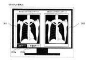
図2は図1のクライアント端末31の画像表示の例を示す図である。
FIG. 2 is a diagram showing an example of image display of the
クライアント端末31の画面には、第1のシンクライアントサーバ12の画面をウィンドウ311に、第2のシンクライアントサーバ22の画面をウィンドウ312に表示する。ウィンドウ311とウィンドウ312には、比較読影を想定して同種でかつ、同じ部位を撮像した画像、ここでは胸部X線画像を例に挙げている。
On the screen of the
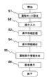
次に、医用画像表示システムの動作について図3乃至図8を用いて説明する。 Next, the operation of the medical image display system will be described with reference to FIGS.
図3は図1の医用画像表示システムの実施例1、2の動作例を示すフローチャート、図4乃至8は実施例1のステップS2乃至S6を説明する状態遷移図である。
FIG. 3 is a flowchart showing an operation example of
医用画像表示システムの操作者は、図2に示すように、連動モード311a又は非連動モード311bの何れかを、画面上に表示したソフトスイッチに対してマウスなどのポインティングデバイスを用いて設定する(ステップS1:連動モード設定)。ここでは、連動モード311aが設定されたとして処理を進める。仮に非連動モード311bが設定されたのであれば、画像拡大処理等の画像処理は一つのシンクライアントサーバでのみ行われる通常動作であるため、ここではその説明を省略する。
As shown in FIG. 2, the operator of the medical image display system sets either the interlocking mode 311a or the
操作者は、図4に示すように、ポインティングデバイスを用いて画像処理メニュー311mの中から画像拡大処理311m1を選択し、さらに例えば第1のシンクライアントサーバ12の画面の拡大したい領域、ここではポインティングデバイスを用いて画面の左肺の上部の領域311sを設定する(ステップS2:操作入力)。
As shown in FIG. 4, the operator selects an image enlargement process 311m1 from the
第1のアプリケーションサーバ11の画面操作情報記憶エリア111には、図5に示されるように、第1のシンクライアントサーバ12に対する画面操作情報1111、すなわち連動モードの設定、画像拡大処理の選択、画面の拡大したい領域が動画記憶される(ステップS3:操作情報記憶)。
In the screen operation
中間サーバ41の画面操作解析部411は、図6に示すように、第1のアプリケーションサーバ11の画面操作情報記憶エリア111の画面操作情報について動画情報を静止画としてコマ送りし、コマ送りされた静止画像について画像認識処理を用いて画面操作情報から連動モードの設定、画像拡大処理の選択、画面の拡大したい領域の選択を認識し、認識された連動モード、画像拡大処理、画面上の拡大領域を第2のアプリケーションサーバ21に出力する(ステップS4:操作情報解析)。
As shown in FIG. 6, the screen
第2のアプリケーションサーバ21の画面操作連動記憶エリア211には、図7に示されるように、第2のシンクライアントサーバ22に対する画面連動操作情報2111、すなわち画像拡大処理の選択、画面の拡大したい領域が第1のシンクライアントサーバ11に連動する連動操作情報が生成され記憶される(ステップS5:連動操作情報生成)。
In the screen operation
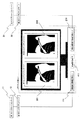
第2のシンクライアントサーバ22は、図8に示すように、ステップS5で記憶された連動操作情報、すなわち画像拡大処理の選択、画面の拡大したい領域を受けて、図7で表示していた表示領域312の画像の左肺の上部の領域を画像拡大処理し、図8のように拡大画像に更新して表示領域312に表示する(ステップS6:画像表示)。
As shown in FIG. 8, the second
以上説明した実施例1によれば、医用画像診断装置によって撮像された医用画像を記憶する第1のシンクライアントサーバ12と、前記第1の医用画像と異なる第2の医用画像を記憶する第2のシンクライアントサーバ22と、前記第1のシンクライアントサーバ12での操作情報を設定するクライアント端末31と、該設定された操作情報を記憶する第1のアプリケーションサーバ11と、該記憶された操作情報に基づき前記第2のシンクライアントサーバ22での操作情報を解析する中間サーバ41と、該解析された操作情報に基づき前記第2のシンクライアントサーバ22の操作を前記第1のシンクライアントサーバ12の操作に連動させて操作するための連動操作情報を生成する第2のアプリケーションサーバ21と、該連動させて操作した前記第2の医用画像を表示するクライアント端末31と、を備えるため、複数のシンクライアントサーバを連動して動作させることが可能な医用画像表示システムを提供できる。
According to the first embodiment described above, the first
また、実施例1の特有の効果は、中間サーバ41が第1のアプリケーションサーバ11の操作を解析し、第2のアプリケーションサーバ22に連動させるため、各サーバ間の役割分担が明確であり、各サーバ間の分散処理システムを構築しやすい効果がある。
In addition, the unique effect of the first embodiment is that the
実施例2では、クライアント端末が複数のシンクライアントサーバの操作記憶機能を担う記憶エリアと連動操作情報解析部を備えている例を説明する。
The second embodiment will explain an example in which the client terminal is provided with an interlock operating information analyzing unit and the serial 憶E rear responsible for operating memory functions of a plurality of thin client server.
図9は本発明の医用画像表示システムの構成例を示すブロック図である。 FIG. 9 is a block diagram showing a configuration example of the medical image display system of the present invention.
医用画像表示システムは、医用画像診断装置によって撮像された医用画像を記憶する第1のシンクライアントサーバ12と、前記第1の医用画像と異なる第2の医用画像を記憶する第2のシンクライアントサーバ22と、前記第1のシンクライアントサーバ12での操作情報を設定する設定部(クライアント端末31)と、該設定された操作情報を記憶する操作情報記憶部(クライアント端末31)と、該記憶された操作情報に基づき前記第2のシンクライアントサーバ22での操作情報を解析する操作情報解析部(クライアント端末31)と、該解析された操作情報に基づき前記第2のシンクライアントサーバ22の操作を前記第1のシンクライアントサーバ12の操作に連動させて操作するための連動操作情報を生成する連動操作情報生成部(クライアント端末31)と、該連動させて操作した前記第2の医用画像を表示する画像表示部(クライアント端末31)と、を備える。
The medical image display system includes a first
実施例1のクライアント端末31の画像表示の例は実施例2でも同様とする。
The image display example of the
次に、医用画像表示システムの動作について図3、図9乃至図13を用いて説明する。 Next, the operation of the medical image display system will be described with reference to FIGS. 3 and 9 to 13.
図9乃至図13は実施例2のステップS2乃至S6を説明する状態遷移図である。 9 to 13 are state transition diagrams illustrating steps S2 to S6 of the second embodiment.
操作者は、実施例1と同様に、連動モード311a又は非連動モード311bの何れかを設定する(ステップS1:連動モード設定)。
As in the first embodiment, the operator sets either the interlocking mode 311a or the
操作者は、図9に示すように、ポインティングデバイスを用いて画像処理メニュー311mの中から画像拡大処理311m1を選択し、さらに例えば第1のシンクライアントサーバ12の画面の拡大したい領域、ここでは画面の左肺の上部の領域311sをポインティングデバイスを用いて設定する(ステップS2:操作入力)。
As shown in FIG. 9, the operator selects an image enlargement process 311m1 from the
クライアント端末31の画面操作情報記憶エリア111には、図10に示されるように、第1のシンクライアントサーバ11に対する画面操作情報1111、すなわち連動モードの設定、画像拡大処理の選択、画面の拡大したい領域が動画記憶される(ステップS3:操作情報記憶)。
In the screen operation
クライアント端末31の画面操作解析部411は、図11に示すように、第1のアプリケーションサーバ11の画面操作情報記憶エリア111の画面操作情報について動画情報を静止画としてコマ送りし、コマ送りされた静止画像について画像認識処理を用いて画面操作情報から連動モードの設定、画像拡大処理の選択、画面の拡大したい領域の選択を認識し、認識された連動モード、画像拡大処理、画面上の拡大領域を第2のアプリケーションサーバ21に出力する(ステップS4:操作情報解析)。
As shown in FIG. 11, the screen
クライアント端末31の画面操作連動記憶エリア211には、図12に示されるように、第2のシンクライアントサーバ22に対する画面連動操作情報2111、すなわち画像拡大処理の選択、画面の拡大したい領域が第1のシンクライアントサーバ11に連動する連動操作情報が生成され記憶される(ステップS5:連動操作情報生成)。
In the screen operation interlocking
第2のシンクライアントサーバ22は、図13に示すように、ステップS5で記憶された連動操作情報、すなわち画像拡大処理の選択、画面の拡大したい領域を受けて、図12で表示していた表示領域312の画像の左肺の上部の領域を画像拡大処理し、図13のように拡大画像に更新して表示領域312に表示する(ステップS6:画像表示)。
Display second
以上説明した実施例2によれば、医用画像診断装置によって撮像された医用画像を記憶する第1のシンクライアントサーバ12と、前記第1の医用画像と異なる第2の医用画像を記憶する第2のシンクライアントサーバ22と、前記第1のシンクライアントサーバ12での操作情報を設定し、該設定された操作情報を記憶し、該記憶された操作情報に基づき前記第2のシンクライアントサーバ22での操作情報を解析し、該解析された操作情報に基づき前記第2のシンクライアントサーバ22の操作を前記第1のシンクライアントサーバ12の操作に連動させて操作するための連動操作情報を生成し、該連動させて操作した前記第2の医用画像を表示するクライアント端末31と、を備えるため、複数のシンクライアントサーバを連動して動作させることが可能な医用画像表示システムを提供できる。
According to the second embodiment described above, the first
また、実施例2の特有の効果は、実施例1におけるアプリケーションサーバや中間サーバの機能をクライアント端末が担うので、中間サーバが不要となることの他に、アプリケーションサーバや中間サーバに例えば3次元画像処理などを分担させることが可能となる効果がある。 In addition, the unique effect of the second embodiment is that the client server functions as the application server and the intermediate server in the first embodiment, so that the intermediate server is not necessary, and the application server and the intermediate server have a 3D image, for example. There is an effect that processing can be shared.
実施例1、2では比較読影の例で説明したが、読影方法は用途に応じてさまざまにマンモ読影、別モダリティ読影などが存在する。そこで、実施例3では読影方法に応じて連動処理を切り替える例を説明する。 In the first and second embodiments, the example of comparative interpretation has been described, but there are various interpretation methods such as mammogram interpretation and different modality interpretation depending on the application. In the third embodiment, an example in which the interlocking process is switched according to the interpretation method will be described.
実施例3のクライアント端末31の画像表示の例は実施例2でも同様とする。
The image display example of the
次に、医用画像表示システムの動作について図14、図15を用いて説明する。 Next, the operation of the medical image display system will be described with reference to FIGS.
図14は図1の医用画像表示システムの実施例3の動作例を示すフローチャート、図15は実施例3のステップS11を説明する状態遷移図である。
FIG. 14 is a flowchart showing an operation example of the medical image display system of FIG. 1 according to the third embodiment, and FIG. 15 is a state transition diagram illustrating step S11 of the third embodiment.
操作者は、実施例1のステップS1に加えて、比較読影311c又はマンモ読影311dの何れかを設定する(ステップS11:読影・連動モード設定)。
In addition to step S1 in the first embodiment, the operator sets either
以降ステップS2:操作入力乃至ステップS6:画像表示までは、実施例1又は2と同じ処理をする。 Thereafter, the same processing as in the first or second embodiment is performed from step S2: operation input to step S6: image display.
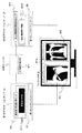
図16は、実施例3のステップS11のその他の例を説明する図で、読影方法を縦軸に、画像処理を横軸にまとめた表を示す。
FIG. 16 is a diagram for explaining another example of step S11 of the third embodiment, and shows a table in which the interpretation method is plotted on the vertical axis and the image processing is plotted on the horizontal axis.
比較読影の欄の画像処理前と画像拡大処理の関係は、実施例1、2で説明したとおりである。同じ欄の画像処理前と白黒反転処理の関係は、実施例1、2の画像拡大処理を白黒反転処理に読み替えて連動処理したものである。 The relationship between the pre-image processing and the image enlargement processing in the comparative interpretation field is as described in the first and second embodiments. The relationship between the image processing before the image processing in the same column and the black and white reversal processing is that the image enlargement processing of the first and second embodiments is replaced with the black and white reversal processing and is interlocked.
次に、マンモ読影は、左右の乳房の画像を対称に表示するもので、画像拡大処理、白黒反転処理が対称表示の関係を維持して連動処理する。 Next, mammogram interpretation displays the images of the left and right breasts symmetrically, and image enlargement processing and black-and-white reversal processing perform interlocking processing while maintaining a symmetrical display relationship.
最後に、別モダリティ読影は、左側にX線CT画像、右側にMRI画像をマルチウィンドウ表示するもので、マルチウィンドウのウィンドウ毎の画像のそれぞれが画像拡大処理などを連動処理する。 Finally, another modality interpretation is to display an X-ray CT image on the left side and an MRI image on the right side in a multi-window display.
以上説明した実施例3によれば、実施例1又は実施例2で説明した効果を奏することができる。 According to the third embodiment described above, the effects described in the first or second embodiment can be achieved.
また、実施例3の特有の効果は、読影方法が異なっても一つのシンクライアントの操作で複数のシンクライアントの操作が可能となる。 In addition, the unique effect of the third embodiment is that a plurality of thin clients can be operated by one thin client operation even if the interpretation method is different.
11 第1のアプリケーションサーバ、21 第2のアプリケーションサーバ、12 第1のシンクライアントサーバ、22 第2のシンクライアントサーバ、31 クライアント端末、41 中間サーバ。 11 first application server, 21 second application server, 12 first thin client server, 22 second thin client server, 31 client terminal, 41 intermediate server.
Claims (5)
前記第1の医用画像と異なる第2の医用画像を記憶する第2のシンクライアントサーバと、
前記第1のシンクライアントサーバでの操作情報を設定する設定部と、
該設定された操作情報を記憶する操作情報記憶部と、
該記憶された操作情報を解析する操作情報解析部と、
該解析された操作情報に基づき前記第2のシンクライアントサーバを前記第1のシンクライアントサーバの操作に連動させて操作するための連動操作情報を生成する連動操作情報生成部と、
該連動させて操作した前記第2のシンクライアントサーバに記憶されている前記第2の医用画像を表示する画像表示部と、を備えたことを特徴とする医用画像表示システム。 A first thin client server for storing a first medical image captured by the medical image diagnostic apparatus;
A second thin client server for storing a second medical image different from the first medical image;
A setting unit for setting operation information in the first thin client server;
An operation information storage unit for storing the set operation information;
An operation information analysis unit for analysis of the operation information the storage,
An interlocking operation information generation unit for generating a synchronous operation information for operating by the second thin client server based on the analyzed operation information in conjunction with the operation of the first thin client server,
A medical image display system comprising: an image display unit configured to display the second medical image stored in the second thin client server operated in conjunction with the second thin client server .
前記連動操作情報生成部が第2のアプリケーションサーバに、
前記操作情報解析部は前記第1のアプリケーションサーバと前記第2のアプリケーションサーバを接続する中間サーバに、
それぞれ具備されることを特徴とする請求項1記載の医用画像表示システム。 The operation information storage unit to the first application server,
To the interlocking operation information generation unit and the second application server,
The operation information analysis unit in the intermediate server connected to the second application server and the first application server,
The medical image display system according to claim 1, wherein the provided respectively and said Rukoto.
前記操作情報解析部が前記操作情報の中からマンモ読影を認識すると、When the operation information analysis unit recognizes a mammogram interpretation from the operation information,
前記連動操作情報生成部は前記連動操作情報に左右を対称に表示させる処理を含ませることを特徴とする請求項4に記載の医用画像表示システム。5. The medical image display system according to claim 4, wherein the interlocking operation information generation unit includes a process of displaying left and right symmetrically in the interlocking operation information.
Priority Applications (1)
| Application Number | Priority Date | Filing Date | Title |
|---|---|---|---|
| JP2013174240A JP6161997B2 (en) | 2013-08-26 | 2013-08-26 | Medical image display system |
Applications Claiming Priority (1)
| Application Number | Priority Date | Filing Date | Title |
|---|---|---|---|
| JP2013174240A JP6161997B2 (en) | 2013-08-26 | 2013-08-26 | Medical image display system |
Publications (3)
| Publication Number | Publication Date |
|---|---|
| JP2015042202A JP2015042202A (en) | 2015-03-05 |
| JP2015042202A5 JP2015042202A5 (en) | 2016-09-15 |
| JP6161997B2 true JP6161997B2 (en) | 2017-07-12 |
Family
ID=52696064
Family Applications (1)
| Application Number | Title | Priority Date | Filing Date |
|---|---|---|---|
| JP2013174240A Active JP6161997B2 (en) | 2013-08-26 | 2013-08-26 | Medical image display system |
Country Status (1)
| Country | Link |
|---|---|
| JP (1) | JP6161997B2 (en) |
Families Citing this family (1)
| Publication number | Priority date | Publication date | Assignee | Title |
|---|---|---|---|---|
| CN111880700B (en) * | 2020-06-09 | 2022-02-01 | 维沃移动通信有限公司 | Application program control method and device and electronic equipment |
Family Cites Families (5)
| Publication number | Priority date | Publication date | Assignee | Title |
|---|---|---|---|---|
| JPH1145334A (en) * | 1997-05-29 | 1999-02-16 | Dainippon Screen Mfg Co Ltd | Comparative display method for images and recording medium |
| JP4401741B2 (en) * | 2003-10-28 | 2010-01-20 | キヤノン株式会社 | Image display device, image display method and program thereof |
| JP2005228227A (en) * | 2004-02-16 | 2005-08-25 | Nippon Telegr & Teleph Corp <Ntt> | Thin client system and its communication method |
| JP6012931B2 (en) * | 2010-03-30 | 2016-10-25 | 東芝メディカルシステムズ株式会社 | Image processing apparatus and control program for image processing apparatus |
| US8995734B2 (en) * | 2012-01-10 | 2015-03-31 | Kabushiki Kaisha Toshiba | Image processing method and system |
-
2013
- 2013-08-26 JP JP2013174240A patent/JP6161997B2/en active Active
Also Published As
| Publication number | Publication date |
|---|---|
| JP2015042202A (en) | 2015-03-05 |
Similar Documents
| Publication | Publication Date | Title |
|---|---|---|
| CA2917196C (en) | Display control apparatus and computer-readable recording medium | |
| JP5946216B2 (en) | Computer having touch panel, operating method thereof, and program | |
| US9898837B2 (en) | Image processing system | |
| CN110326292B (en) | Image display device, image display method, and storage medium | |
| JPWO2019203351A1 (en) | Image display device and image display method | |
| US20170229102A1 (en) | Techniques for descriptor overlay superimposed on an asset | |
| US9690458B2 (en) | Image viewing method for displaying portion of selected image based on user interaction input and related image viewing system and machine readable medium | |
| JP5875415B2 (en) | Image synthesizer | |
| JP2016019248A (en) | Motion picture display control device, motion picture display control method and program | |
| JP5728588B2 (en) | Display control method, computer program, display control apparatus, and image display system | |
| JP6161997B2 (en) | Medical image display system | |
| US11494934B2 (en) | Image processing device, image processing method, and monitoring system | |
| JP2012156797A (en) | Image processing apparatus and image processing method | |
| JP2016128893A (en) | Image processing device and image processing method | |
| JP2015042202A5 (en) | ||
| US20200193651A1 (en) | Medical image display device and medical image display system | |
| JP7099064B2 (en) | Display control device, medical image display system and program | |
| JP6716519B2 (en) | Display device and display method | |
| JP2002101428A (en) | Image stereoscopic vision display device | |
| JP6470136B2 (en) | Screen image generator | |
| JP2013201697A (en) | Depth creation support device, depth creation support method, and program | |
| JP2018125746A (en) | Image output device, control method and program thereof | |
| JP2023176248A (en) | Information processing device and information processing method | |
| JP2021010102A (en) | Information processing device, information processing method, and program | |
| JP6224407B2 (en) | Display device and display method |
Legal Events
| Date | Code | Title | Description |
|---|---|---|---|
| A711 | Notification of change in applicant |
Free format text: JAPANESE INTERMEDIATE CODE: A712 Effective date: 20160427 |
|
| A621 | Written request for application examination |
Free format text: JAPANESE INTERMEDIATE CODE: A621 Effective date: 20160725 |
|
| A521 | Request for written amendment filed |
Free format text: JAPANESE INTERMEDIATE CODE: A523 Effective date: 20160802 |
|
| TRDD | Decision of grant or rejection written | ||
| A977 | Report on retrieval |
Free format text: JAPANESE INTERMEDIATE CODE: A971007 Effective date: 20170519 |
|
| A01 | Written decision to grant a patent or to grant a registration (utility model) |
Free format text: JAPANESE INTERMEDIATE CODE: A01 Effective date: 20170530 |
|
| A61 | First payment of annual fees (during grant procedure) |
Free format text: JAPANESE INTERMEDIATE CODE: A61 Effective date: 20170614 |
|
| R150 | Certificate of patent or registration of utility model |
Ref document number: 6161997 Country of ref document: JP Free format text: JAPANESE INTERMEDIATE CODE: R150 |
|
| S111 | Request for change of ownership or part of ownership |
Free format text: JAPANESE INTERMEDIATE CODE: R313111 |
|
| R350 | Written notification of registration of transfer |
Free format text: JAPANESE INTERMEDIATE CODE: R350 |
|
| R250 | Receipt of annual fees |
Free format text: JAPANESE INTERMEDIATE CODE: R250 |
|
| R250 | Receipt of annual fees |
Free format text: JAPANESE INTERMEDIATE CODE: R250 |