JP6161917B2 - Control system for cooling fan for vehicle and control method thereof - Google Patents
Control system for cooling fan for vehicle and control method thereof Download PDFInfo
- Publication number
- JP6161917B2 JP6161917B2 JP2013032187A JP2013032187A JP6161917B2 JP 6161917 B2 JP6161917 B2 JP 6161917B2 JP 2013032187 A JP2013032187 A JP 2013032187A JP 2013032187 A JP2013032187 A JP 2013032187A JP 6161917 B2 JP6161917 B2 JP 6161917B2
- Authority
- JP
- Japan
- Prior art keywords
- control device
- vehicle
- fan
- motor
- controls
- Prior art date
- Legal status (The legal status is an assumption and is not a legal conclusion. Google has not performed a legal analysis and makes no representation as to the accuracy of the status listed.)
- Expired - Fee Related
Links
Images


Classifications
-
- B—PERFORMING OPERATIONS; TRANSPORTING
- B60—VEHICLES IN GENERAL
- B60H—ARRANGEMENTS OF HEATING, COOLING, VENTILATING OR OTHER AIR-TREATING DEVICES SPECIALLY ADAPTED FOR PASSENGER OR GOODS SPACES OF VEHICLES
- B60H1/00—Heating, cooling or ventilating [HVAC] devices
- B60H1/00642—Control systems or circuits; Control members or indication devices for heating, cooling or ventilating devices
- B60H1/00814—Control systems or circuits characterised by their output, for controlling particular components of the heating, cooling or ventilating installation
- B60H1/00821—Control systems or circuits characterised by their output, for controlling particular components of the heating, cooling or ventilating installation the components being ventilating, air admitting or air distributing devices
- B60H1/00828—Ventilators, e.g. speed control
-
- B—PERFORMING OPERATIONS; TRANSPORTING
- B60—VEHICLES IN GENERAL
- B60H—ARRANGEMENTS OF HEATING, COOLING, VENTILATING OR OTHER AIR-TREATING DEVICES SPECIALLY ADAPTED FOR PASSENGER OR GOODS SPACES OF VEHICLES
- B60H1/00—Heating, cooling or ventilating [HVAC] devices
- B60H1/00421—Driving arrangements for parts of a vehicle air-conditioning
- B60H1/00428—Driving arrangements for parts of a vehicle air-conditioning electric
-
- B—PERFORMING OPERATIONS; TRANSPORTING
- B60—VEHICLES IN GENERAL
- B60H—ARRANGEMENTS OF HEATING, COOLING, VENTILATING OR OTHER AIR-TREATING DEVICES SPECIALLY ADAPTED FOR PASSENGER OR GOODS SPACES OF VEHICLES
- B60H1/00—Heating, cooling or ventilating [HVAC] devices
- B60H1/00642—Control systems or circuits; Control members or indication devices for heating, cooling or ventilating devices
- B60H1/00978—Control systems or circuits characterised by failure of detection or safety means; Diagnostic methods
-
- B—PERFORMING OPERATIONS; TRANSPORTING
- B60—VEHICLES IN GENERAL
- B60H—ARRANGEMENTS OF HEATING, COOLING, VENTILATING OR OTHER AIR-TREATING DEVICES SPECIALLY ADAPTED FOR PASSENGER OR GOODS SPACES OF VEHICLES
- B60H1/00—Heating, cooling or ventilating [HVAC] devices
- B60H1/02—Heating, cooling or ventilating [HVAC] devices the heat being derived from the propulsion plant
- B60H1/04—Heating, cooling or ventilating [HVAC] devices the heat being derived from the propulsion plant from cooling liquid of the plant
- B60H1/08—Heating, cooling or ventilating [HVAC] devices the heat being derived from the propulsion plant from cooling liquid of the plant from other radiator than main radiator
- B60H1/10—Heating, cooling or ventilating [HVAC] devices the heat being derived from the propulsion plant from cooling liquid of the plant from other radiator than main radiator the other radiator being situated in a duct capable of being connected to atmosphere outside vehicle
- B60H1/12—Heating, cooling or ventilating [HVAC] devices the heat being derived from the propulsion plant from cooling liquid of the plant from other radiator than main radiator the other radiator being situated in a duct capable of being connected to atmosphere outside vehicle using an air blower
-
- B—PERFORMING OPERATIONS; TRANSPORTING
- B60—VEHICLES IN GENERAL
- B60R—VEHICLES, VEHICLE FITTINGS, OR VEHICLE PARTS, NOT OTHERWISE PROVIDED FOR
- B60R16/00—Electric or fluid circuits specially adapted for vehicles and not otherwise provided for; Arrangement of elements of electric or fluid circuits specially adapted for vehicles and not otherwise provided for
- B60R16/02—Electric or fluid circuits specially adapted for vehicles and not otherwise provided for; Arrangement of elements of electric or fluid circuits specially adapted for vehicles and not otherwise provided for electric constitutive elements
- B60R16/023—Electric or fluid circuits specially adapted for vehicles and not otherwise provided for; Arrangement of elements of electric or fluid circuits specially adapted for vehicles and not otherwise provided for electric constitutive elements for transmission of signals between vehicle parts or subsystems
-
- F—MECHANICAL ENGINEERING; LIGHTING; HEATING; WEAPONS; BLASTING
- F01—MACHINES OR ENGINES IN GENERAL; ENGINE PLANTS IN GENERAL; STEAM ENGINES
- F01P—COOLING OF MACHINES OR ENGINES IN GENERAL; COOLING OF INTERNAL-COMBUSTION ENGINES
- F01P11/00—Component parts, details, or accessories not provided for in, or of interest apart from, groups F01P1/00 - F01P9/00
- F01P11/14—Indicating devices; Other safety devices
-
- F—MECHANICAL ENGINEERING; LIGHTING; HEATING; WEAPONS; BLASTING
- F01—MACHINES OR ENGINES IN GENERAL; ENGINE PLANTS IN GENERAL; STEAM ENGINES
- F01P—COOLING OF MACHINES OR ENGINES IN GENERAL; COOLING OF INTERNAL-COMBUSTION ENGINES
- F01P5/00—Pumping cooling-air or liquid coolants
- F01P5/02—Pumping cooling-air; Arrangements of cooling-air pumps, e.g. fans or blowers
- F01P5/04—Pump-driving arrangements
-
- F—MECHANICAL ENGINEERING; LIGHTING; HEATING; WEAPONS; BLASTING
- F01—MACHINES OR ENGINES IN GENERAL; ENGINE PLANTS IN GENERAL; STEAM ENGINES
- F01P—COOLING OF MACHINES OR ENGINES IN GENERAL; COOLING OF INTERNAL-COMBUSTION ENGINES
- F01P7/00—Controlling of coolant flow
- F01P7/02—Controlling of coolant flow the coolant being cooling-air
- F01P7/04—Controlling of coolant flow the coolant being cooling-air by varying pump speed, e.g. by changing pump-drive gear ratio
-
- F—MECHANICAL ENGINEERING; LIGHTING; HEATING; WEAPONS; BLASTING
- F04—POSITIVE - DISPLACEMENT MACHINES FOR LIQUIDS; PUMPS FOR LIQUIDS OR ELASTIC FLUIDS
- F04D—NON-POSITIVE-DISPLACEMENT PUMPS
- F04D27/00—Control, e.g. regulation, of pumps, pumping installations or pumping systems specially adapted for elastic fluids
- F04D27/004—Control, e.g. regulation, of pumps, pumping installations or pumping systems specially adapted for elastic fluids by varying driving speed
-
- F—MECHANICAL ENGINEERING; LIGHTING; HEATING; WEAPONS; BLASTING
- F04—POSITIVE - DISPLACEMENT MACHINES FOR LIQUIDS; PUMPS FOR LIQUIDS OR ELASTIC FLUIDS
- F04D—NON-POSITIVE-DISPLACEMENT PUMPS
- F04D27/00—Control, e.g. regulation, of pumps, pumping installations or pumping systems specially adapted for elastic fluids
- F04D27/008—Stop safety or alarm devices, e.g. stop-and-go control; Disposition of check-valves
-
- F—MECHANICAL ENGINEERING; LIGHTING; HEATING; WEAPONS; BLASTING
- F01—MACHINES OR ENGINES IN GENERAL; ENGINE PLANTS IN GENERAL; STEAM ENGINES
- F01P—COOLING OF MACHINES OR ENGINES IN GENERAL; COOLING OF INTERNAL-COMBUSTION ENGINES
- F01P2031/00—Fail safe
- F01P2031/36—Failure of coolant pump
-
- F—MECHANICAL ENGINEERING; LIGHTING; HEATING; WEAPONS; BLASTING
- F04—POSITIVE - DISPLACEMENT MACHINES FOR LIQUIDS; PUMPS FOR LIQUIDS OR ELASTIC FLUIDS
- F04D—NON-POSITIVE-DISPLACEMENT PUMPS
- F04D25/00—Pumping installations or systems
- F04D25/02—Units comprising pumps and their driving means
- F04D25/08—Units comprising pumps and their driving means the working fluid being air, e.g. for ventilation
-
- Y—GENERAL TAGGING OF NEW TECHNOLOGICAL DEVELOPMENTS; GENERAL TAGGING OF CROSS-SECTIONAL TECHNOLOGIES SPANNING OVER SEVERAL SECTIONS OF THE IPC; TECHNICAL SUBJECTS COVERED BY FORMER USPC CROSS-REFERENCE ART COLLECTIONS [XRACs] AND DIGESTS
- Y02—TECHNOLOGIES OR APPLICATIONS FOR MITIGATION OR ADAPTATION AGAINST CLIMATE CHANGE
- Y02B—CLIMATE CHANGE MITIGATION TECHNOLOGIES RELATED TO BUILDINGS, e.g. HOUSING, HOUSE APPLIANCES OR RELATED END-USER APPLICATIONS
- Y02B30/00—Energy efficient heating, ventilation or air conditioning [HVAC]
- Y02B30/70—Efficient control or regulation technologies, e.g. for control of refrigerant flow, motor or heating
-
- Y—GENERAL TAGGING OF NEW TECHNOLOGICAL DEVELOPMENTS; GENERAL TAGGING OF CROSS-SECTIONAL TECHNOLOGIES SPANNING OVER SEVERAL SECTIONS OF THE IPC; TECHNICAL SUBJECTS COVERED BY FORMER USPC CROSS-REFERENCE ART COLLECTIONS [XRACs] AND DIGESTS
- Y02—TECHNOLOGIES OR APPLICATIONS FOR MITIGATION OR ADAPTATION AGAINST CLIMATE CHANGE
- Y02T—CLIMATE CHANGE MITIGATION TECHNOLOGIES RELATED TO TRANSPORTATION
- Y02T10/00—Road transport of goods or passengers
- Y02T10/80—Technologies aiming to reduce greenhouse gasses emissions common to all road transportation technologies
- Y02T10/88—Optimized components or subsystems, e.g. lighting, actively controlled glasses
Description
本発明は、車両用クーリングファン用制御システム及びその制御方法に関するものである。 The present invention relates to a vehicle cooling fan control system and a control method therefor.
従来、車載の熱交換器のクーリングファンを制御するファン制御装置は、車両用ECU(Electronic Control Unit)の配下に配置されており、クーリングファン制御は、車両用ECUから出力されるPWM(pulse width moduration)信号のデューティ比によってモータの回転数制御が行われている。
モータ回転数は、車速、エンジン冷却水温、AC圧力に基づき速度制御される。エアコンがオン状態の場合は、エアコンの圧力信号と車両側から受けた車速信号に基づき、エアコンECUで必要ファン制御を演算し、車両用ECUに出力する。車両用ECUはその信号に、さらに車速とエンジン冷却水温を加味してファンモータの回転数を決定し、ファン駆動用PWM信号を出力する。一方、エアコンがオフ状態の場合は、車速とエンジン冷却水温に基づき車両用ECUでファン回転数を決定し、ファン駆動用PWM信号を出力する。
2. Description of the Related Art Conventionally, a fan control device that controls a cooling fan of an in-vehicle heat exchanger is disposed under a vehicle ECU (Electronic Control Unit), and the cooling fan control is performed by PWM (pulse width) output from the vehicle ECU. The number of revolutions of the motor is controlled by the duty ratio of the modulation signal.
The motor speed is controlled based on the vehicle speed, engine coolant temperature, and AC pressure. When the air conditioner is on, the air conditioner ECU calculates the necessary fan control based on the pressure signal of the air conditioner and the vehicle speed signal received from the vehicle side, and outputs it to the vehicle ECU. The vehicle ECU further determines the number of rotations of the fan motor by adding the vehicle speed and the engine coolant temperature to the signal, and outputs a fan drive PWM signal. On the other hand, when the air conditioner is off, the vehicle ECU determines the fan speed based on the vehicle speed and the engine coolant temperature, and outputs a fan drive PWM signal.
ところで、このような車両システム構成においては、クーリングファンを駆動させるファンモータに異常が発生した場合であっても、車両用ECUからファン制御装置側へPWM信号を一方的に送るだけであり、ファン制御装置側と車両用ECUとは通信手段が設けられておらず、車両側でファンモータの異常を発見できないという問題があった。また、個別のハーネスを介して車両用ECUとファン制御装置とが繋がれており、車両内配線が煩雑になるためファン制御装置側の異常を車両側に通知させることが困難であった。 By the way, in such a vehicle system configuration, even if an abnormality occurs in the fan motor that drives the cooling fan, the PWM signal is only unilaterally sent from the vehicle ECU to the fan control device side. There is a problem in that no communication means is provided between the control device side and the vehicle ECU, and an abnormality of the fan motor cannot be found on the vehicle side. In addition, since the vehicle ECU and the fan control device are connected via individual harnesses, and wiring in the vehicle becomes complicated, it is difficult to notify the vehicle side of the abnormality on the fan control device side.
本発明は、上記問題を解決するためになされたもので、簡便な配線でファンモータの異常を車両側で検出することのできる車両用クーリングファン用制御システム及びその制御方法を提供することを目的とする。 The present invention has been made to solve the above problems, and an object of the present invention is to provide a vehicle cooling fan control system and a control method thereof that can detect an abnormality of the fan motor on the vehicle side with simple wiring. And
上記課題を解決するために、本発明は以下の手段を採用する。 In order to solve the above problems, the present invention employs the following means.
本発明は、車載の熱交換器に空気を供給するクーリングファンを駆動する三相モータを制御するモータ制御装置を有するファン制御装置と、前記ファン制御装置の上位の車両を制御する第1制御装置と、前記車両の空気調和装置を制御する第2制御装置とを備える車両用クーリングファン用制御システムであって、前記ファン制御装置と、前記第1制御装置と、前記第2制御装置とが車両ネットワークを介して相互に情報の授受可能に接続されており、前記ファン制御装置は、前記モータ制御装置が備えるスイッチング素子に、火災や感電につながる危険性のある重要度の高い異常を検出した場合に、前記車両ネットワークを介して異常情報を出力し、前記第1制御装置は、前記異常情報を取得した場合には、前記車両ネットワークを介して前記ファン制御装置及び前記第2制御装置を保護制御する車両用クーリングファン用制御システムを提供する。 The present invention relates to a fan control device having a motor control device that controls a three-phase motor that drives a cooling fan that supplies air to an in-vehicle heat exchanger, and a first control device that controls a vehicle above the fan control device. And a cooling fan control system for controlling a vehicle air conditioner, wherein the fan control device, the first control device, and the second control device are vehicles. When the fan control device detects a highly important abnormality that may lead to fire or electric shock in the switching element of the motor control device, connected to each other via a network. the outputs abnormality information through the vehicle network, the first control device, when acquiring the abnormality information through the vehicle network Providing serial fan control apparatus and a control system for a vehicle cooling fan to protect controlling said second controller.
このような構成によれば、車載の熱交換器に空気を供給するクーリングファンを駆動する三相モータを制御するモータ制御装置を有するファン制御装置と、ファン制御装置の上位の車両を制御する第1制御装置と、車両の空気調和装置を制御する第2制御装置とが車両ネットワークを介して相互に情報の授受可能に接続されており、モータ制御装置に備えられているスイッチング素子に異常が検出された場合に、モータ制御装置から車両ネットワークを介して異常情報が出力され、異常情報を取得した第1制御装置は、異常情報が重要度の高い異常である場合に、車両ネットワークを介してファン制御装置及び第2制御装置を保護制御する。
ここで、スイッチング素子は、半導体素子で構成されるパワートランジスタであり、例えば、MOSFET(Metal−Oxide−Semiconductor Field−Effect Transistor)、バイポーラトランジスタ、及びIGBT(Insulated Gate Bipolar Transistor)等が使用される。また、半導体材料としては、Si(シリコン)系半導体やSiC(炭化珪素)系半導体が用いられる。
According to such a configuration, the fan control device having the motor control device that controls the three-phase motor that drives the cooling fan that supplies the air to the on-vehicle heat exchanger, and the first vehicle that controls the vehicle above the fan control device. 1 control device and a second control device that controls a vehicle air conditioner are connected to each other via a vehicle network so that information can be exchanged between them, and an abnormality is detected in a switching element provided in the motor control device. When the abnormality information is output from the motor control device via the vehicle network, the first control device that has acquired the abnormality information receives the fan information via the vehicle network when the abnormality information is a highly important abnormality. The control device and the second control device are protected and controlled.
Here, the switching element is a power transistor composed of a semiconductor element, and for example, a MOSFET (Metal-Oxide-Semiconductor-Effect Transistor), a bipolar transistor, and an IGBT (Insulated Gate Bipolar Transistor) are used. As the semiconductor material, a Si (silicon) based semiconductor or a SiC (silicon carbide) based semiconductor is used.
これにより、車両ネットワークを介して三相モータの異常情報が車両側に報告されるので、車両側でクーリングファンを駆動する三相モータの異常を検出でき、重要度の高い異常が生じた場合には車両側の制御装置(第1制御装置)から、空気調和装置を制御する第2制御装置とモータ制御装置とが保護制御されることにより、重大な事故を未然に防止することができ、原因究明に役立てることができる。ここで、重要度の高い異常情報とは、人に危害を加える可能性のある異常であり、例えば、過電流が頻繁に生じる、三相モータの絶縁不良・断線、短絡破壊など、火災や感電につながる危険性のある異常である。
また、ファン制御装置と第1制御装置と第2制御装置とはそれぞれ相互に車両ネットワークを介して情報の授受可能に接続されているので、ファン制御装置は、従来のPWM制御による回転数制御と比較してきめ細やかで速やかな反応が望めるので、三相モータの状態に応じて空気調和装置を精度よく制御でき、快適・緻密なエアコン制御につながる。
As a result, the abnormality information of the three-phase motor is reported to the vehicle side via the vehicle network, so that the abnormality of the three-phase motor that drives the cooling fan can be detected on the vehicle side, and when a highly important abnormality occurs The vehicle control device (first control device) can prevent and prevent serious accidents by protecting and controlling the second control device that controls the air conditioner and the motor control device. It can be used for investigation. Here, high-priority abnormality information is an abnormality that may cause harm to humans.For example, there are frequent overcurrents, three-phase motor insulation failure / disconnection, short circuit failure, etc. It is an abnormality that may lead to
In addition, since the fan control device, the first control device, and the second control device are connected to each other so as to be able to exchange information via the vehicle network, the fan control device can perform the rotational speed control by the conventional PWM control. Compared with this, it is possible to expect a more detailed and quick reaction, so that the air conditioner can be controlled accurately according to the state of the three-phase motor, leading to comfortable and precise air conditioning control.
上記車両用クーリングファン用制御システムの前記第2制御装置は、前記第2制御装置は、重要度の高い異常が検出される場合以外の通常状態である場合に、前記車両ネットワークを介して前記ファン制御装置を制御することが好ましい。
これにより、通常状態である場合は、車両側の上位系やCAN等の通信系に負荷をかけない。
The second control device of the vehicle cooling fan control system is configured such that the second control device is configured to operate the fan via the vehicle network when the second control device is in a normal state other than when a highly important abnormality is detected. It is preferable to control the control device.
Thereby, when it is a normal state, load is not applied to communication systems, such as a higher system by the side of a vehicle, and CAN.
上記車両用クーリングファン用制御システムは、前記ファン制御装置と、前記第2制御装置とは、前記ファン制御装置内の前記スイッチング素子をデューティに応答して制御させるPWM信号を授受する通信ネットワークで接続されており、前記ファン制御装置は、PWM制御に基づいて、前記通信ネットワークを介して前記モータ制御装置の前記スイッチング素子を制御するPWM制御手段と、前記車両ネットワークを介して情報を授受する通信制御手段とを有しており、前記PWM制御手段及び前記通信制御手段のうち少なくともどちらか一方を介して、前記三相モータの回転数指示を取得することとしてもよい。 In the vehicle cooling fan control system, the fan control device and the second control device are connected by a communication network that transmits and receives a PWM signal for controlling the switching element in the fan control device in response to a duty. And the fan control device, based on PWM control, PWM control means for controlling the switching element of the motor control device via the communication network, and communication control for exchanging information via the vehicle network. And a rotation speed instruction of the three-phase motor may be acquired via at least one of the PWM control unit and the communication control unit.
ファン制御装置は、通信ネットワークを介しても、車両ネットワークを介しても、回転数指示を取得することができるので、従来型のPWMデューティによる制御であっても、近年主流になっている車両ネットワーク(例えば、CAN(Controller Area Network)通信、LIN(Local Interconnect Network)通信等)による制御であっても、対応できる。 Since the fan control device can acquire the rotation speed instruction via the communication network or the vehicle network, the vehicle network that has become the mainstream in recent years even with the conventional PWM duty control. (For example, control by CAN (Controller Area Network) communication, LIN (Local Interconnect Network) communication, etc.) can be supported.
本発明は、車載の熱交換器に空気を供給するクーリングファンを駆動する三相モータを制御するモータ制御装置を有するファン制御装置と、前記ファン制御装置の上位の車両を制御する第1制御装置と、前記車両の空気調和装置を制御する第2制御装置とを備える制御システムの制御方法であって、前記ファン制御装置と、前記第1制御装置と、前記第2制御装置とが車両ネットワークを介して相互に情報の授受可能に接続されている場合に、前記モータ制御装置に備えられるスイッチング素子に、火災や感電につながる危険性のある重要度の高い異常が検出された場合に、前記車両ネットワークを介して前記モータ制御装置から異常情報を出力させ、 前記異常情報を取得した場合には、前記第1制御装置によって、前記車両ネットワークを介して前記ファン制御装置及び第2制御装置を保護制御する車両用クーリングファン用制御システムの制御方法を提供する。 The present invention relates to a fan control device having a motor control device that controls a three-phase motor that drives a cooling fan that supplies air to an in-vehicle heat exchanger, and a first control device that controls a vehicle above the fan control device. And a second control device for controlling the air conditioner of the vehicle, wherein the fan control device, the first control device, and the second control device form a vehicle network. And when the vehicle is connected so that information can be exchanged between them, the switching element provided in the motor control device detects a highly important abnormality that may lead to a fire or electric shock. When the abnormality information is output from the motor control device via a network and the abnormality information is acquired , the vehicle network is controlled by the first control device. A control method for a vehicle cooling fan control system for protecting and controlling the fan control device and the second control device is provided.
本発明によれば、簡便な配線でファンモータの異常を車両側で検出するという効果を奏する。 According to the present invention, it is possible to detect an abnormality of the fan motor on the vehicle side with simple wiring.
以下に、本発明に係る車両用クーリングファン用制御システム及びその制御方法の実施形態について図面を参照して説明する。なお、本実施形態の車両用クーリングファン用制御システムのファン制御装置は、車両の熱交換器(ラジエータ)用のクーリングファンを駆動するモータの制御に用いることを例に挙げて説明する。 DESCRIPTION OF EMBODIMENTS Embodiments of a vehicle cooling fan control system and a control method thereof according to the present invention will be described below with reference to the drawings. Note that the fan control device of the vehicle cooling fan control system according to the present embodiment will be described by way of example for use in controlling a motor for driving a cooling fan for a vehicle heat exchanger (radiator).
〔第1の実施形態〕
図1は、本実施形態に係る制御システム(車両用クーリングファン用制御システム)1の概略構成図を示している。
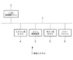
図1に示されるように、制御システム1は、ラジエータに空気を供給するクーリングファンを駆動する三相モータを制御するモータ制御装置を有するファン制御装置2と、ファン制御装置2の上位にある、車両を制御する車両側ECU(第1制御装置)3と、車両の空気調和装置を制御するエアコン系ECU(第2制御装置)4と、内装などのボディ系を制御するボディ系ECU5と、エンジンで発生したエネルギーを駆動輪に伝えるパワートレイン6とを備えている。なお、図1に示されていないその他車両コンポーネントが車両ネットワークに接続されているシステムであっても本発明が適用できることはいうまでもない。
[First Embodiment]
FIG. 1 is a schematic configuration diagram of a control system (vehicle cooling fan control system) 1 according to the present embodiment.
As shown in FIG. 1, the control system 1 is located above the
制御システム1は、ファン制御装置2と、車両側ECU3と、エアコン系ECU4と、ボディ系ECU5と、パワートレイン6とが車両ネットワークCAN7を介して相互に情報の授受可能に接続されている。
なお、本実施形態においては、車両ネットワークとしてCANを利用することを例に挙げて説明するが、これに限定されず、例えば、LINや、FlexRay等の他の方式であってもよく、特に限定されない。
In the control system 1, a
In the present embodiment, the use of CAN as a vehicle network will be described as an example. However, the present invention is not limited to this. For example, other methods such as LIN and FlexRay may be used. Not.
図2は、本実施形態に係るファン制御装置2の機能ブロック図が示されている。
ファン制御装置2は、三相モータ30と、三相モータ30を駆動するインバータシステム20とを備えている。
インバータシステム20は、スイッチング素子22を有するモータ制御装置21と、計測部23と、第3制御部24と、絶縁部8とを備えている。モータ制御装置21は、高電圧バッテリや発電機等の高電圧電源40から供給される直流電流を三相の交流電流に変換し、三相モータ30を駆動する。高電圧電源40は、例えば、200〔V〕や400〔V〕の電圧であり、HVフィルタ26を介してモータ制御装置21に電力供給している。低電圧電源50は、車載バッテリ電源等であり、例えば、12〔V〕の電圧を供給する。
ここで、スイッチング素子22は、半導体素子で構成されるパワートランジスタであり、例えば、MOSFET、バイポーラトランジスタ、及びIGBT等が使用される。また、半導体材料としては、Si系半導体やSiC系半導体が用いられる。
FIG. 2 is a functional block diagram of the
The
The
Here, the switching
絶縁部8は、低電圧電源50から電力が供給される低電圧系統9と、高電圧電源40から電力が供給される高電圧系統10とを電気的に絶縁させる。また、絶縁部8は、低電圧電源50から供給される電力によって作動し、具体的には、絶縁型のDC−DCコンバータ81と、絶縁型のCANドライバ(通信制御手段)82とを備えている。
The insulating unit 8 electrically insulates the
絶縁型のDC−DCコンバータ81は、モータ制御装置21及び第3制御部24に対し、低電圧電源50の電力を供給する。また、絶縁型のDC−DCコンバータ81が供給する電力は、第3制御部24の駆動電圧(例えば、5〔V〕)や、モータ制御装置21の駆動電圧(例えば、15〔V〕)として用いられる。
絶縁型のCANドライバ82は、車両ネットワークCAN7と接続されており、車両ネットワークCAN7を介して車両側ECU3に接続され、車両側ECU3と第3制御部24との間で情報を授受する。
The insulated DC-
The
ファン制御装置2は、モータ制御装置21が備えるスイッチング素子22に異常が検出された場合に、車両ネットワークCAN7と接続されるCANドライバ82を介して異常情報を出力する。
車両側ECU3は、異常情報が重要度の高い異常である場合には、車両ネットワークCAN7を介してファン制御装置2及びエアコン系ECU4を保護制御する。ここで、重要度の高い異常情報とは、人に危害を加える可能性のある異常であり、例えば、スイッチング素子22に過電流が頻繁に生じる、三相モータの絶縁不良・断線、短絡破壊など、火災や感電につながる危険性のある異常である。
エアコン系ECU4は、重大な異常が検出される場合以外の通常状態である場合に、車両ネットワークCAN7を介して、ファン制御装置2を制御する。これにより、通常状態である場合は、車両側の上位系やCAN等の通信系に負荷をかけずに済む。
When an abnormality is detected in the switching
The vehicle-
The air
第3制御部24は、モータ制御装置21を制御する。具体的には、第3制御部24は、CANドライバ82を介して、三相モータ30の回転数指示を取得し、取得した回転数指示に基づいて三相モータ30を制御する。
The
第3制御部24は、判定部25を備えている。判定部25は、計測部23から取得した温度値、電流値、及び電圧値のうち少なくともいずれか一に基づいて、スイッチング素子22の異常有無を判定する。具体的には、判定部25は、温度値、電流値、及び電圧値に関する閾値を有しており、所定の閾値を超過した場合に重要度が高い異常と判定し、判定結果を車両ネットワークCAN7を介して車両側ECU3に出力する。なお、判定部25が備える閾値は、温度値、電流値、及び電圧値に関する値そのものに限定されず、それらを検出する繰り返し回数によって決められていてもよい。
また、第3制御部24は、スイッチング素子22に重要度が高い異常が検出された場合に、CANドライバ82を介して、車両側ECU3に対して、三相モータ30の制御に異常がある旨を通知する異常情報を出力する。
The
The
計測部23は、モータ制御装置21のスイッチング素子22の温度値、電流値、及び電圧値のうち少なくともいずれか一を計測し、第3制御部24に出力する。例えば、三相モータ30やモータ制御装置21のスイッチング素子22が故障している場合、スイッチング素子22の温度が高温となるので、計測部23によりスイッチング素子22の温度変化を検出し、第3制御部24において故障有無を判定させる。
The
次に、本実施形態に係る制御システム1の作用について説明する。
車両に搭載される高電圧電源40からモータ制御装置21に供給された直流電力は、三相の交流電流に変換され、三相モータ30に給電されて三相モータ30を駆動させる。CANドライバ82を介して車両側に設けられている車両側ECU3から取得される三相モータ30の回転数指示に基づいて、モータ制御装置21が制御される。これにより、三相モータ30が回転駆動され、ラジエータ用クーリングファンが作動する。
スイッチング素子22の温度値、電流値、及び電圧値が計測されており、計測結果は第3制御部24に出力される。計測結果が所定の閾値と比較され、閾値を超過せず通常状態の場合は、エアコン系ECU4がファン制御装置2を制御する。また、計測結果が所定の閾値を超過している場合に、重要度が高い異常と判断されて、車両ネットワークCAN7を介して車両側ECU3に対して、異常情報が通知される。
Next, the operation of the control system 1 according to this embodiment will be described.
The DC power supplied from the high-
The temperature value, current value, and voltage value of the switching
車両側の制御回路である車両側ECU3において、車両ネットワークCAN7を介してファン制御装置2から異常情報が取得されると、ラジエータ用クーリングファンにおいて異常が発生したことが検出される。提示部(図示略)等を介してラジエータ用クーリングファンに異常が発生したことが提示されることにより、車両の運転者によって異常を把握させることができる。
また、車両側ECU3は、異常情報を検出すると、エアコン系ECU4と、ファン制御装置2と、ボディ系ECU5と、パワートレイン6とを含む車両全体を保護制御し、これにより、異常情報に起因する重大な事故を未然に防止できる。
In the vehicle-
Further, when the vehicle-
以上説明してきたように、本実施形態に係る制御システム1及びその制御方法において、車載のラジエータ用クーリングファンを駆動する三相モータ30を制御するモータ制御装置21を有するファン制御装置2と、ファン制御装置2の上位の車両側ECU3と、車両の空気調和装置を制御するエアコン系ECU4とが車両ネットワークCAN7を介して情報の授受可能に接続されており、モータ制御装置21に備えられているスイッチング素子22に異常が検出された場合には、モータ制御装置21から車両ネットワークCAN7を介して異常情報が出力され、異常情報を取得した車両側ECU3は、異常情報が重要度の高い異常である場合に、車両ネットワークCAN7を介してファン制御装置2及びエアコン系ECU4を保護制御する。
As described above, in the control system 1 and the control method thereof according to the present embodiment, the
これにより、車両ネットワークCAN7を介して三相モータ30の異常情報が車両側に報告されるので、車両側でクーリングファンを駆動する三相モータ30の異常を検出でき、重要度の高い異常が生じた場合には車両側ECU3から、エアコン系ECU4とモータ制御装置21とが保護制御されることにより、重大な事故を未然に防止することができ、原因究明に役立てることができる。
また、ファン制御装置2と車両側ECU3とエアコン系ECU4とはそれぞれ相互にCAN(車両ネットワーク)7を介して情報の授受可能に接続されることにより、従来のPWM制御による回転数制御と比較してきめ細やかで速やかな反応が望めるので、三相モータ30の状態に応じて空気調和装置を精度よく制御でき、快適・緻密なエアコン制御につながる。
As a result, the abnormality information of the three-
Further, the
〔変形例〕
なお、本実施形態においては、ファン制御装置2が通常状態である場合に、エアコン系ECU4が車両ネットワークCAN7を介してファン制御装置2を制御することとして説明していたが、これに限定されない。例えば、図3に示されるように、ファン制御装置2が、低電圧電源50から供給される電力によって作動し、デューティに応答してPWM制御を行って、モータ制御装置21のスイッチング素子22を制御する絶縁型のPWMドライバ83を有している場合には、エアコン系ECU4は、PWM信号を用いて三相モータ30の回転数制御をすることとしてもよい。
[Modification]
In the present embodiment, the air-
具体的には、ファン制御装置2と、エアコン系ECU4とは、ファン制御装置2内のスイッチング素子22をデューティに応答して制御させるPWM信号を授受する通信ネットワーク84で接続させる。また、ファン制御装置2は、PWM制御に基づいて、モータ制御装置21のスイッチング素子22を制御するPWMドライバ83と、車両ネットワークCAN7を介して情報を授受するCANドライバ82とを有しており、PWMドライバ83及びCANドライバ82のうち少なくともどちらか一方を介して、三相モータ30の回転数指示を取得する。
このように、ファン制御装置2とエアコン系ECU4とが、車両ネットワークCAN7に加え、PWM信号の授受可能に接続されていれば、従来車両に用いられている空調システムのハード、ソフトを流用することができる。また、CAN通信の場合は、PWM信号を用いる場合と比較してノイズに強いので、CAN通信を用いることによりノイズの影響を抑えて回転数指示を正確に行うことができる。
Specifically, the
In this way, if the
〔第2の実施形態〕
次に、本発明の第2の実施形態について図4を用いて説明する。
本実施形態の制御システムが第1の実施形態と異なる点は、モータ制御装置が低電圧電源から給電される点で、上記第1の実施形態と異なる。以下、本実施形態の制御システムについて、第1の実施形態と共通する点については説明を省略し、異なる点について主に説明する。
[Second Embodiment]
Next, a second embodiment of the present invention will be described with reference to FIG.
The difference of the control system of the present embodiment from the first embodiment is that the motor control device is supplied with power from a low-voltage power supply, and is different from the first embodiment. Hereinafter, regarding the control system of the present embodiment, description of points that are common to the first embodiment will be omitted, and different points will be mainly described.
図4に示されるように、本実施形態に係るファン制御装置2´は、単相モータ30´と、モータ制御装置21´と、第3制御部24とを備えており、車内ネットワークである車両ネットワークCAN7と接続されている。また、ファン制御装置2´は、低電圧電源50から電力を得ており、モータ制御装置21´は、非絶縁型のDC−DCコンバータ81´を介して低電圧電源50の電力を得て単相モータ30´に供給している。このように、低電圧電源50の電力が単相モータ30´の駆動用電源となっている。
As shown in FIG. 4, the
このように、モータ駆動に低電圧電源50を用いるファン制御装置2´であっても、車両ネットワークCAN7を介して車両側ECU3と接続されるので、車両側に単相モータ30´の異常を検出できる。また、重要度の高い異常が生じた場合には車両側ECU3から、エアコン系ECU4とモータ制御装置21とが保護制御されることにより、重大な事故を未然に防止することができ、原因究明に役立てることができる。
As described above, even the
1 制御システム
2 ファン制御装置
3 車両側ECU(第1制御装置)
4 エアコン系ECU(第2制御装置)
7 車両ネットワークCAN(車両ネットワーク)
8 絶縁部
20 インバータシステム
21 モータ制御装置
22 スイッチング素子
24 第3制御部
81 DC−DCコンバータ
82 CANドライバ(通信制御手段)
83 PWMドライバ(PWM制御手段)
DESCRIPTION OF SYMBOLS 1
4 Air conditioning system ECU (second control device)
7 Vehicle Network CAN (Vehicle Network)
8 Insulating
83 PWM driver (PWM control means)
Claims (4)
前記ファン制御装置と、前記第1制御装置と、前記第2制御装置とが車両ネットワークを介して相互に情報の授受可能に接続されており、
前記ファン制御装置は、前記モータ制御装置が備えるスイッチング素子に、火災や感電につながる危険性のある重要度の高い異常を検出した場合に、前記車両ネットワークを介して異常情報を出力し、
前記第1制御装置は、前記異常情報を取得した場合には、前記車両ネットワークを介して前記ファン制御装置及び前記第2制御装置を保護制御する車両用クーリングファン用制御システム。 A fan control device having a motor control device that controls a three-phase motor that drives a cooling fan that supplies air to an on-vehicle heat exchanger, a first control device that controls a vehicle above the fan control device, and the vehicle A control system for a cooling fan for a vehicle, comprising: a second control device that controls the air conditioner of
The fan control device, the first control device, and the second control device are connected to each other via a vehicle network so as to be able to exchange information.
The fan control device outputs abnormality information via the vehicle network when detecting a highly important abnormality that may lead to a fire or an electric shock in the switching element provided in the motor control device,
When the first control device acquires the abnormality information, the first control device protects and controls the fan control device and the second control device via the vehicle network.
前記ファン制御装置は、PWM制御に基づいて、前記通信ネットワークを介して前記モータ制御装置の前記スイッチング素子を制御するPWM制御手段と、前記車両ネットワークを介して情報を授受する通信制御手段とを有しており、前記PWM制御手段及び前記通信制御手段のうち少なくともどちらか一方を介して、前記三相モータの回転数指示を取得する請求項1または請求項2に記載の車両用クーリングファン用制御システム。 The fan control device and the second control device are connected by a communication network that transmits and receives a PWM (pulse width modulation) signal that controls the switching element in the fan control device in response to a duty.
The fan control device has PWM control means for controlling the switching element of the motor control device via the communication network based on PWM control, and communication control means for transferring information via the vehicle network. The vehicle cooling fan control according to claim 1, wherein an instruction for the number of rotations of the three-phase motor is acquired via at least one of the PWM control unit and the communication control unit. system.
前記ファン制御装置と、前記第1制御装置と、前記第2制御装置とが車両ネットワークを介して相互に情報の授受可能に接続されている場合に、
前記モータ制御装置に備えられるスイッチング素子に、火災や感電につながる危険性のある重要度の高い異常が検出された場合に、前記車両ネットワークを介して前記モータ制御装置から異常情報を出力させ、
前記異常情報を取得した場合には、前記第1制御装置によって、前記車両ネットワークを介して前記ファン制御装置及び前記第2制御装置を保護制御する車両用クーリングファン用制御システムの制御方法。 A fan control device having a motor control device that controls a three-phase motor that drives a cooling fan that supplies air to an on-vehicle heat exchanger, a first control device that controls a vehicle above the fan control device, and the vehicle And a second control device for controlling the air conditioner of the control system,
When the fan control device, the first control device, and the second control device are connected to each other via a vehicle network so as to be able to exchange information,
When a highly important abnormality with a risk of causing a fire or an electric shock is detected in the switching element provided in the motor control device, the abnormality information is output from the motor control device via the vehicle network,
When acquiring the abnormality information, the by the first control device, a control method of the fan control unit and the second control device for a vehicle cooling fan control system for protecting control over the vehicle network.
Priority Applications (5)
| Application Number | Priority Date | Filing Date | Title |
|---|---|---|---|
| JP2013032187A JP6161917B2 (en) | 2013-02-21 | 2013-02-21 | Control system for cooling fan for vehicle and control method thereof |
| CN201380071765.8A CN104981378B (en) | 2013-02-21 | 2013-10-29 | The control system and its control method of vehicle cooling fan |
| PCT/JP2013/079303 WO2014129019A1 (en) | 2013-02-21 | 2013-10-29 | Control system for cooling fan for vehicles and control method therefor |
| US14/760,606 US9421847B2 (en) | 2013-02-21 | 2013-10-29 | Vehicle-cooling-fan control system and control method therefor |
| DE112013006707.2T DE112013006707T5 (en) | 2013-02-21 | 2013-10-29 | Vehicle cooling fan control system and control method for it |
Applications Claiming Priority (1)
| Application Number | Priority Date | Filing Date | Title |
|---|---|---|---|
| JP2013032187A JP6161917B2 (en) | 2013-02-21 | 2013-02-21 | Control system for cooling fan for vehicle and control method thereof |
Publications (3)
| Publication Number | Publication Date |
|---|---|
| JP2014162252A JP2014162252A (en) | 2014-09-08 |
| JP2014162252A5 JP2014162252A5 (en) | 2016-03-17 |
| JP6161917B2 true JP6161917B2 (en) | 2017-07-12 |
Family
ID=51390836
Family Applications (1)
| Application Number | Title | Priority Date | Filing Date |
|---|---|---|---|
| JP2013032187A Expired - Fee Related JP6161917B2 (en) | 2013-02-21 | 2013-02-21 | Control system for cooling fan for vehicle and control method thereof |
Country Status (5)
| Country | Link |
|---|---|
| US (1) | US9421847B2 (en) |
| JP (1) | JP6161917B2 (en) |
| CN (1) | CN104981378B (en) |
| DE (1) | DE112013006707T5 (en) |
| WO (1) | WO2014129019A1 (en) |
Families Citing this family (4)
| Publication number | Priority date | Publication date | Assignee | Title |
|---|---|---|---|---|
| CN105317521B (en) * | 2015-11-13 | 2017-11-03 | 湖州职业技术学院 | A kind of electric engine cooling fan multilevel control system |
| DE102017107277A1 (en) * | 2017-04-05 | 2018-10-11 | Hanon Systems | Arrangement and method for updating a control software in a high-voltage control unit |
| CN114056111B (en) * | 2020-08-06 | 2024-03-01 | 华为数字能源技术有限公司 | Motor drive control device, power system and electric automobile |
| WO2023286023A1 (en) * | 2021-07-15 | 2023-01-19 | Tata Motors Limited | Method and system for controlling speed of a blower unit in a vehicle |
Family Cites Families (6)
| Publication number | Priority date | Publication date | Assignee | Title |
|---|---|---|---|---|
| JP2005080384A (en) * | 2003-08-29 | 2005-03-24 | Calsonic Kansei Corp | Electric fan control unit |
| JP2005299407A (en) | 2004-04-07 | 2005-10-27 | Toyota Motor Corp | Cooling system, method for controlling the same, and automobile |
| US20060120903A1 (en) * | 2004-12-06 | 2006-06-08 | Denso Corporation | Electric fan system for vehicle |
| JP2007049835A (en) * | 2005-08-10 | 2007-02-22 | Hitachi Ltd | Device and method for controlling rotating electric machine |
| US7425812B2 (en) * | 2005-11-23 | 2008-09-16 | Standard Microsystems Corporation | Ramp rate closed-loop control (RRCC) for PC cooling fans |
| JP5549505B2 (en) * | 2010-09-28 | 2014-07-16 | 日産自動車株式会社 | Temperature protection device, motor control device, and temperature protection method |
-
2013
- 2013-02-21 JP JP2013032187A patent/JP6161917B2/en not_active Expired - Fee Related
- 2013-10-29 DE DE112013006707.2T patent/DE112013006707T5/en not_active Withdrawn
- 2013-10-29 CN CN201380071765.8A patent/CN104981378B/en not_active Expired - Fee Related
- 2013-10-29 US US14/760,606 patent/US9421847B2/en active Active
- 2013-10-29 WO PCT/JP2013/079303 patent/WO2014129019A1/en active Application Filing
Also Published As
| Publication number | Publication date |
|---|---|
| CN104981378B (en) | 2018-05-18 |
| WO2014129019A1 (en) | 2014-08-28 |
| JP2014162252A (en) | 2014-09-08 |
| CN104981378A (en) | 2015-10-14 |
| US20150360540A1 (en) | 2015-12-17 |
| DE112013006707T5 (en) | 2015-11-05 |
| US9421847B2 (en) | 2016-08-23 |
Similar Documents
| Publication | Publication Date | Title |
|---|---|---|
| JP6012506B2 (en) | Cooling fan motor / inverter system for vehicle, control method and program thereof | |
| US10044297B2 (en) | Method and apparatus for controlling an electric motor of a cooling fan | |
| JP6161917B2 (en) | Control system for cooling fan for vehicle and control method thereof | |
| JP6239020B2 (en) | Control device and control method for electric vehicle | |
| JP6522232B2 (en) | Overheat protection control device and power circuit device for vehicle | |
| US9106173B2 (en) | Motor driving device and method of protecting motor driving device | |
| JP5786452B2 (en) | High voltage cable protection system | |
| EP3306813B1 (en) | Power conversion device | |
| JP6259975B2 (en) | Overvoltage protection measures for active rectifiers during load shedding | |
| JP7061060B2 (en) | Control circuit, drive system and inverter control method | |
| JP5473212B2 (en) | Inverter system for in-vehicle air conditioner | |
| JP6508024B2 (en) | Power converter | |
| JP7103115B2 (en) | Power converter | |
| JP2013236437A (en) | Controller of dynamo-electric machine | |
| JP5111208B2 (en) | Power converter | |
| US20150015178A1 (en) | Method and apparatus for monitoring and controlling a synchronous electric machine | |
| JP6207973B2 (en) | Motor control device | |
| US9148082B2 (en) | Control device and control method | |
| US11811349B2 (en) | Method and system for regulating electric drive system according to predicted temperature of inverter current sensor to prevent overheating | |
| JP7407768B2 (en) | power converter | |
| JP5906877B2 (en) | Protection device for electric equipment | |
| JPH07125938A (en) | Control device for elevator | |
| WO2022038718A1 (en) | Control method for hybrid vehicle and control device for hybrid vehicle | |
| US20230255006A1 (en) | Method and System for Controlling Electric Drive System According to Predicted Temperature of Inverter Busbar | |
| JP2005117754A (en) | Inverter device |
Legal Events
| Date | Code | Title | Description |
|---|---|---|---|
| A521 | Written amendment |
Free format text: JAPANESE INTERMEDIATE CODE: A523 Effective date: 20160201 |
|
| A621 | Written request for application examination |
Free format text: JAPANESE INTERMEDIATE CODE: A621 Effective date: 20160201 |
|
| A131 | Notification of reasons for refusal |
Free format text: JAPANESE INTERMEDIATE CODE: A131 Effective date: 20161108 |
|
| A521 | Written amendment |
Free format text: JAPANESE INTERMEDIATE CODE: A523 Effective date: 20161227 |
|
| TRDD | Decision of grant or rejection written | ||
| A01 | Written decision to grant a patent or to grant a registration (utility model) |
Free format text: JAPANESE INTERMEDIATE CODE: A01 Effective date: 20170516 |
|
| A61 | First payment of annual fees (during grant procedure) |
Free format text: JAPANESE INTERMEDIATE CODE: A61 Effective date: 20170614 |
|
| R150 | Certificate of patent or registration of utility model |
Ref document number: 6161917 Country of ref document: JP Free format text: JAPANESE INTERMEDIATE CODE: R150 |
|
| S111 | Request for change of ownership or part of ownership |
Free format text: JAPANESE INTERMEDIATE CODE: R313111 |
|
| R350 | Written notification of registration of transfer |
Free format text: JAPANESE INTERMEDIATE CODE: R350 |
|
| LAPS | Cancellation because of no payment of annual fees |