JP6160680B2 - Joint type forming machine for linear steel sheet pile and method for producing linear steel sheet pile - Google Patents
Joint type forming machine for linear steel sheet pile and method for producing linear steel sheet pile Download PDFInfo
- Publication number
- JP6160680B2 JP6160680B2 JP2015233692A JP2015233692A JP6160680B2 JP 6160680 B2 JP6160680 B2 JP 6160680B2 JP 2015233692 A JP2015233692 A JP 2015233692A JP 2015233692 A JP2015233692 A JP 2015233692A JP 6160680 B2 JP6160680 B2 JP 6160680B2
- Authority
- JP
- Japan
- Prior art keywords
- steel sheet
- sheet pile
- rolling
- linear steel
- pair
- Prior art date
- Legal status (The legal status is an assumption and is not a legal conclusion. Google has not performed a legal analysis and makes no representation as to the accuracy of the status listed.)
- Active
Links
Images


Classifications
-
- B—PERFORMING OPERATIONS; TRANSPORTING
- B21—MECHANICAL METAL-WORKING WITHOUT ESSENTIALLY REMOVING MATERIAL; PUNCHING METAL
- B21B—ROLLING OF METAL
- B21B1/00—Metal-rolling methods or mills for making semi-finished products of solid or profiled cross-section; Sequence of operations in milling trains; Layout of rolling-mill plant, e.g. grouping of stands; Succession of passes or of sectional pass alternations
- B21B1/08—Metal-rolling methods or mills for making semi-finished products of solid or profiled cross-section; Sequence of operations in milling trains; Layout of rolling-mill plant, e.g. grouping of stands; Succession of passes or of sectional pass alternations for rolling structural sections, i.e. work of special cross-section, e.g. angle steel
- B21B1/082—Piling sections having lateral edges specially adapted for interlocking with each other in order to build a wall
-
- B—PERFORMING OPERATIONS; TRANSPORTING
- B21—MECHANICAL METAL-WORKING WITHOUT ESSENTIALLY REMOVING MATERIAL; PUNCHING METAL
- B21B—ROLLING OF METAL
- B21B39/00—Arrangements for moving, supporting, or positioning work, or controlling its movement, combined with or arranged in, or specially adapted for use in connection with, metal-rolling mills
- B21B39/14—Guiding, positioning or aligning work
Description
本開示は、直線型鋼矢板の継手部成型機及び直線型鋼矢板の製造方法に関する。 The present disclosure relates to a joint forming machine for a linear steel sheet pile and a method for manufacturing the linear steel sheet pile.
長手方向及び幅方向に垂直な上下方向に対して非対称(以下、「上下非対称」ともいう。)な形状を有する直線型鋼矢板の圧延は、一般的に専用鋼片(BB)もしくは矩形鋼片(BL)を素材として、二重式圧延機で圧延されることが多い。この場合、ロールの摩耗や、圧延材の長手方向全長にわたっての圧延温度、圧下調整による圧延荷重の変化等の影響により、長手方向全長において継手部の開口幅が変動し、目的とする寸法・形状が得られないことがある。 The rolling of a linear steel sheet pile having an asymmetrical shape (hereinafter also referred to as “vertical asymmetry”) with respect to the vertical direction perpendicular to the longitudinal direction and the width direction is generally performed using a dedicated steel slab (BB) or a rectangular steel slab ( It is often rolled by a double rolling mill using BL) as a raw material. In this case, the opening width of the joint part fluctuates over the entire length in the longitudinal direction due to the wear of the roll, the rolling temperature over the entire length in the longitudinal direction of the rolled material, the change in rolling load due to the reduction adjustment, etc. May not be obtained.
例えば、特許文献1〜4には、上下方向に対して対称(以下、「上下対称」ともいう。)な形状を有する直線型鋼矢板を圧延する方法として、ユニバーサル圧延機を適用した圧延において、突起付きの竪ロールを継手部の開口部へ嵌入させる方法が開示されている。特許文献1〜4によれば、ユニバーサル圧延機の竪ロールの突起を開口部に嵌入させた状態で、継手部の爪を最終的に曲げこむことにより、圧延材のセンタリング性を確保しつつ、継手部の成型性を向上させることができる。
For example, in
ところで、上下非対称な直線型鋼矢板を圧延する場合、上下対称な直線型鋼矢板に比べ、造形孔型の数が多くなり、より多くの圧延機を設ける必要があるため、ユニバーサル圧延機を適用することが難しい。このため、上下非対称な直線型鋼矢板の圧延には、通常、二重式圧延機が用いられるが、上述の継手部の寸法制御性及び形状成型性が低いことが問題となる。継手部の寸法制御性及び形状成型性が低く、例えば、継手部の開口幅が目標のものよりも狭い場合、鋼矢板の施工性となる鋼矢板同士の嵌合性が悪くなる。
このような問題に対して、圧延する際に圧延材の温度を長手方向全長にわたって均一にすることや、ロールの摩耗を発生させないように圧延することが望ましいが、現実的には困難となる。
By the way, when rolling up and down asymmetrical linear steel sheet piles, it is necessary to install a universal rolling mill because the number of forming hole molds is larger than that of a vertically symmetrical linear steel sheet pile and it is necessary to provide more rolling mills. Is difficult. For this reason, a double rolling mill is usually used for rolling a vertical steel sheet pile that is asymmetrical in the vertical direction, but there is a problem that the dimension controllability and shape formability of the joint portion described above are low. When the joint part has low dimensional controllability and shape moldability, for example, when the opening width of the joint part is narrower than the target, the fitability of the steel sheet piles, which is the workability of the steel sheet piles, becomes poor.
In order to solve such a problem, it is desirable to make the temperature of the rolled material uniform over the entire length in the longitudinal direction when rolling, or to roll so as not to cause wear of the roll, but this is difficult in practice.
そこで、本発明は、上記の課題に着目してなされたものであり、直線型鋼矢板の継手部の寸法制御性及び形状成型性を向上させることができる、直線型鋼矢板の継手部成型機及び直線型鋼矢板の製造方法を提供することを目的としている。 Therefore, the present invention has been made paying attention to the above-described problem, and can improve the dimension controllability and shape moldability of the joint part of the linear steel sheet pile, and the linear steel sheet pile joint part molding machine and the straight line It aims at providing the manufacturing method of a type steel sheet pile.
本発明の一態様によれば、幅方向に延在するウェブ部と、該ウェブ部の両端に形成され2つの爪をそれぞれ有する継手部とを有する上下非対称な直線型鋼矢板を圧延する二重式圧延機の最終成型圧延が行われる圧延ロールの出側に設けられ、圧延される上記直線型鋼矢板の上記ウェブ部を挟んで設けられる1対のウェブガイドローラと、上記1対のウェブガイドローラよりも上記直線型鋼矢板の圧延方向の下流側に設けられ、径方向外方に突出し上記2つの爪の先端間に形成される開口部に嵌入可能な突出部を上記圧延方向及び上記直線型鋼矢板の幅方向に垂直な上下方向の中央に有し、上記継手部に上記幅方向の外側からそれぞれ当接する1対の成型ガイドローラとを備えることを特徴とする直線型鋼矢板の継手部成型機が提供される。 According to one aspect of the present invention, a double type of rolling a vertically asymmetric linear steel sheet pile having a web portion extending in the width direction and joint portions each having two claws formed at both ends of the web portion. From a pair of web guide rollers provided on the exit side of the rolling roll in which the final forming rolling of the rolling mill is performed and provided between the web portion of the linear steel sheet pile to be rolled, and the pair of web guide rollers Is provided on the downstream side of the linear steel sheet pile in the rolling direction, and protrudes radially outward and can be fitted into an opening formed between the tips of the two claws. Provided is a linear steel sheet pile joint part molding machine comprising a pair of molding guide rollers that are provided at the center in the vertical direction perpendicular to the width direction and abut against the joint part from the outside in the width direction. Is done.
本発明の一態様によれば、幅方向に延在するウェブ部と、該ウェブ部の両端に形成され2つの爪をそれぞれ有する継手部とを有する上下非対称な直線型鋼矢板を、二重式圧延機を用いて圧延して製造する際に、上記二重式圧延機の最終成型圧延の後、上記最終成型圧延が行われる圧延ロールの出側に設けられ、圧延される上記直線型鋼矢板の上記ウェブ部を挟んで設けられる1対のウェブガイドローラを用いて、上記直線型鋼矢板のセンタリング性を確保し、上記1対のウェブガイドローラよりも上記直線型鋼矢板の圧延方向の下流側に設けられ、径方向外方に突出し上記継手部の2つの爪の先端間に形成される開口部に嵌入可能な突出部を上記圧延方向及び上記直線型鋼矢板の幅方向に垂直な上下方向の中央に有し、上記継手部に上記幅方向の外側からそれぞれ当接する1対の成型ガイドローラを、上記継手部に上記幅方向の外側からそれぞれ当接させることを特徴とする直線型鋼矢板の製造方法が提供される。 According to one aspect of the present invention, a vertically asymmetric linear steel sheet pile having a web portion extending in the width direction and joint portions each having two claws formed at both ends of the web portion is double-rolled. When rolling and manufacturing using a mill, after the final forming rolling of the double rolling mill, the linear steel sheet pile is provided on the exit side of the rolling roll on which the final forming rolling is performed, and is rolled. Using a pair of web guide rollers provided with a web portion interposed therebetween, the centering property of the linear steel sheet pile is ensured, and provided more downstream in the rolling direction of the linear steel sheet pile than the pair of web guide rollers. A projecting portion projecting radially outward and capable of being fitted into an opening formed between the tips of the two claws of the joint portion at the center in the vertical direction perpendicular to the rolling direction and the width direction of the linear steel sheet pile. And the above width A pair molded guide rollers which from the outside to abut each method of linear steel sheet pile, characterized in that to respectively abut the outer side of the width direction in the joint portion is provided.
本発明の一態様によれば、直線型鋼矢板の継手部の寸法制御性及び形状成型性を向上させることができる、直線型鋼矢板の継手部成型機及び直線型鋼矢板の製造方法を提供することができる。 According to one aspect of the present invention, it is possible to provide a joint forming machine for a linear steel sheet pile and a method for manufacturing the linear steel sheet pile that can improve the dimensional controllability and shape moldability of the joint of the linear steel sheet pile. it can.
以下の詳細な説明では、本発明の実施形態の完全な理解を提供するように多くの特定の細部について記載される。しかしながら、かかる特定の細部がなくても1つ以上の実施態様が実施できることは明らかであろう。他にも、図面を簡潔にするために、周知の構造及び装置が略図で示されている。
<直線型鋼矢板>
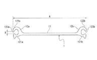
はじめに、図1〜図3を参照して、本発明の一実施形態において圧延される直線型鋼矢板1について説明する。直線型鋼矢板1は、図1に示すように幅方向(図1の紙面に対する左右方向)に延在するウェブ部11と、幅方向の両端側に1対の継手部12a,12bとを有する。継手部12a,12bは、幅方向及び長手方向(図1の紙面に対する前後方向)に垂直な上下方向(図1の紙面に対する上下方向)に対して非対称な、上下非対称の形状を有する。継手部12a,12bは、下側に形成され幅方向に対して湾曲した主爪121a,121bと、上側に形成され幅方向に対して湾曲した副爪122a,122bとの2つの爪を有する。主爪121a,121bの先端と副爪122a,122bの先端との間には、開口部123a,123bがそれぞれ形成される。また、本実施形態では、直線型鋼矢板1の幅方向の長さを全幅Aといい、開口部123a,123bの上下方向の長さを開口幅Bという。
In the following detailed description, numerous specific details are set forth in order to provide a thorough understanding of embodiments of the present invention. However, it will be apparent that one or more embodiments may be practiced without such specific details. In other instances, well-known structures and devices are schematically shown in order to simplify the drawing.
<Linear steel sheet pile>
First, with reference to FIGS. 1-3, the linear
このような直線型鋼矢板1は、高い寸法・形状の精度が求められる。特に、継手部12a,12bにおいては、施工性の観点から高い寸法・形状精度が求められる。しかし、二重式圧延機を用いて直線型鋼矢板1を圧延する場合、上述のように、ロールの摩耗や、圧延材の長手方向全長にわたる圧延温度、圧下調整による圧延荷重の変化等によって、継手部12a,12bの寸法・形状が全長で変化する。特に、こうした継手部12a,12bの寸法・形状の変化の中でも、開口幅Bの変動が施工性の観点から問題となる。例えば、長手方向の先端側では開口幅Bが広めとなった場合においても、圧延条件によっては尾端側では開口幅Bが狭くなる場合がある。
Such a linear
継手部12a,12bにおける形状不良の例を図2に示す。図2(a)は、主爪121a及び副爪122aの曲がりこみ過多によって、実際の開口幅B1が目標となる開口幅Bよりも狭くなり、下限外れとなった例を示す。図2(a)に示す形状不良の例では、実際の開口幅B1が狭くなりすぎるために、施工時において他の直線型鋼矢板の継手部との嵌合性が悪くなる。図2(b)は、副爪122aの曲げ不足及び主爪121aの変形により、実際の開口幅B1が目標となる開口幅Bよりも広くなり、上限外れとなった例を示す。図2(b)においても、実際の開口幅B1が広くなりすぎたために、施工時において嵌合性が悪くなる可能性がある。また、図2(b)のように、副爪122aの曲げ不足がある場合、実際の全幅A1が目標となる全幅Aよりも大きくなり、上限外れとなる場合がある。このため、直線型鋼矢板1の製造にあたっては、継手部12a,12bの寸法・形状の精度を高めることが肝要となる。
An example of a shape defect in the
<圧延設備の構成>
次に、図3〜図7を参照して、本実施形態の圧延設備について説明する。圧延設備は、図3に示すように、加熱炉2と、粗圧延機3と、中間圧延機4と、仕上圧延機5とを備える。
加熱炉2は、圧延材である矩形鋼片を所定の温度まで加熱する加熱設備である。
<Configuration of rolling equipment>
Next, the rolling equipment of this embodiment is demonstrated with reference to FIGS. As shown in FIG. 3, the rolling equipment includes a
The
粗圧延機3は、1基のミル(1対のロール)を有する二重式圧延機であり、このロールに3か所の孔型であるカリバーK12〜K10が長手方向に並んで設けられる。各カリバーK12〜K10は、後述するように、粗圧延工程において圧延材が目標とする断面形状となるような形状をそれぞれ有する。
中間圧延機4は、2基のミル4a,4bを有する二重式タンデム圧延機である。ミル4aには3か所のカリバーK9,K6,K5、ミル4bには3か所のカリバーK8,K7,K4が、粗圧延機3と同様に、長手方向に並んでそれぞれ設けられる。各カリバーK9〜K4は、後述するように、中間圧延工程において圧延材が目標とする断面形状となるような形状をそれぞれ有する。
The rough rolling mill 3 is a double rolling mill having one mill (a pair of rolls), and calibers K12 to K10, which are three hole types, are provided side by side in the longitudinal direction on this roll. As will be described later, each caliber K12 to K10 has a shape such that the rolled material has a target cross-sectional shape in the rough rolling step.
The intermediate rolling mill 4 is a double tandem rolling mill having two
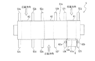
仕上圧延機5は、図4及び図5に示すように、1基のミルである上ロール51a及び下ロール51bを有する二重式圧延機であり、上ロール51a及び下ロール51bに3か所のカリバーK3,K2,K1が設けられる。各カリバーK3〜K1は、後述するように、仕上圧延工程において圧延材が目標とする断面形状となるような形状をそれぞれ有する。また、仕上圧延機5は、6対のサイドガイド52a〜52lと、1対のウェブガイド53a,53bと、継手部成型機6とを有する。
As shown in FIGS. 4 and 5, the finish rolling mill 5 is a double rolling mill having an
6対のサイドガイド52a〜52lは、各カリバーK3,K2,K1に応じた上ロール51a及び下ロール51bの圧延方向の入側または出側に設けられる。サイドガイド52a,52bはカリバーK3の入側、サイドガイド52c,52dはカリバーK3の出側、サイドガイド52e,52fはカリバーK2の入側、サイドガイド52g,52hはカリバーK2の出側、サイドガイド52i,52jはカリバーK1の入側及びサイドガイド52k,52lはカリバーK1の出側にそれぞれ設けられる。各カリバーK1〜K3の入側または出側に対に設けられたサイドガイド52a〜52lは、通過する圧延材を挟んで設けられ、各カリバーK3,K2,K1に入出する圧延材の幅方向の位置合わせを補助する。
The six pairs of side guides 52a to 52l are provided on the entry side or the exit side in the rolling direction of the
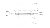
1対のウェブガイド53a,53bは、後述する最終成型圧延が行われるカリバーK1の出側、且つ1対のサイドガイド52k,52lの間に、上下方向に対向して設けられる。ウェブガイド53aの圧延方向上流側の先端は上ロール51aに接するように配され、ウェブガイド53bの圧延方向上流側の先端は下ロール51bに接するように配される。1対のウェブガイド53a,53bは、カリバーK1で成型圧延された圧延材である直線型鋼矢板1の上ロール51aまたは下ロール51bへの貼りつきを防止し、上ロール51aまたは下ロール51bに貼りついた直線型鋼矢板1を上ロール51aまたは下ロール51bから剥がす。
The pair of web guides 53a and 53b are provided opposite to each other in the vertical direction on the exit side of the caliber K1 where final molding and rolling described later is performed and between the pair of side guides 52k and 52l. The front end of the
継手部成型機6は、図4〜図6に示すように、1対のウェブガイドローラ61a,61bと、1対の成型ガイドローラ62a,62bとを有する。
1対のウェブガイドローラ61a,61bは、回転軸が幅方向に平行に配されるロールである。1対のウェブガイドローラ61a,61bは、上下方向に離隔して、1対のウェブガイド53a,53b内にそれぞれ設けられる。なお、1対のウェブガイドローラ61a,61bは、後述するように、通材する直線型鋼矢板1の上下方向の位置精度であるセンタリング性を確保できるように、所定の高さに所定距離だけ離間してそれぞれ設けられる。
The joint
The pair of
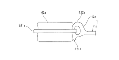
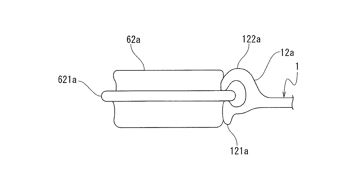
1対の成型ガイドローラ62a,62bは、回転軸が上下方向に平行に配されるロールである。1対の成型ガイドローラ62a,62bは、1対のウェブガイドローラ61a,61bよりも圧延方向の下流側に、幅方向に離間して、1対のサイドガイド52k,52l内にそれぞれ設けられる。また、1対の成型ガイドローラ62a,62bは、1対のサイドガイド52k,52l内に設けられる不図示の移動機構によって、幅方向に移動可能にそれぞれ設けられる。なお、1対の成型ガイドローラ62a,62bは、通過する直線型鋼矢板1の継手部12a,12bに当接するように移動機構によって幅方向に移動調整された後、直線型鋼矢板1の圧延時には、幅方向に移動しないように固定される。
The pair of
また、1対の成型ガイドローラ62a,62bは、図6に示すように、上下方向の中央に、径方向外方に突出する突出部621a,621bを有する。突出部621a,621bの上下方向の幅及び突出長さは、図7に示すように、目標とする継手部12a,12bの形状・寸法(開口幅Bや主爪121a,121b及び副爪122a,122bの形状・寸法)に応じて設定される。さらに、1対の成型ガイドローラ62a,62bの突出部621a,621bを挟んだ上側及び下側の表面は、目標とする継手部12a,12bの形状・寸法に応じて、湾曲した形状を有する。
Further, as shown in FIG. 6, the pair of
<直線型鋼矢板の製造方法>
次に、図3及び図8を参照して、本実施形態に係る直線型鋼矢板1の製造方法について説明する。
本実施形態では、まず、加熱炉2で矩形鋼片BLが所定の温度まで加熱される。
次いで、加熱された矩形鋼片BLが圧延材として粗圧延機3に搬送され、粗圧延機3にて粗圧延される(粗圧延工程)。粗圧延工程では、粗圧延機3のカリバーK12〜K10にて圧延材が順に圧延される。なお、図3に示すように、圧延材は、各カリバーK12〜K10にて複数回(パス)圧延される。粗圧延工程では、上述の粗圧延が行われることで、図8に示すように、長手方向に垂直な圧延材の断面形状が順に変化する。
<Method for producing linear steel sheet pile>
Next, with reference to FIG.3 and FIG.8, the manufacturing method of the linear
In the present embodiment, first, the rectangular steel piece BL is heated to a predetermined temperature in the
Next, the heated rectangular steel slab BL is conveyed to the roughing mill 3 as a rolled material, and is roughly rolled by the roughing mill 3 (rough rolling process). In the rough rolling process, the rolled material is sequentially rolled by the calibers K12 to K10 of the rough rolling mill 3. In addition, as shown in FIG. 3, a rolling material is rolled in multiple times (pass) in each caliber K12-K10. In the rough rolling step, the above-described rough rolling is performed, so that the cross-sectional shape of the rolled material perpendicular to the longitudinal direction changes in order as shown in FIG.
さらに、粗圧延された圧延材が中間圧延機4に搬送され、中間圧延機4にて中間圧延される(中間圧延工程)。中間圧延工程では、図3に示すように、中間圧延機4のカリバーK9〜K4にて圧延材が順に圧延される。これにより、図8に示すように、圧延材の断面形状が順に変化する。
その後、中間圧延された圧延材が仕上圧延機5に搬送され、仕上圧延機5にて仕上圧延される(仕上圧延工程)。仕上圧延工程では、図3に示すように、仕上圧延機5のカリバーK3〜K1にて圧延材が順に圧延される。これにより、図8に示すように、圧延材の断面形状が順に変化する。
Further, the roughly rolled material is conveyed to the intermediate rolling mill 4 and subjected to intermediate rolling by the intermediate rolling mill 4 (intermediate rolling process). In the intermediate rolling process, as shown in FIG. 3, the rolled material is rolled in order by calibers K9 to K4 of the intermediate rolling mill 4. Thereby, as shown in FIG. 8, the cross-sectional shape of a rolling material changes in order.
Thereafter, the intermediate rolled material is conveyed to the finish rolling mill 5 and finish-rolled by the finish rolling mill 5 (finish rolling process). In the finish rolling process, as shown in FIG. 3, the rolled material is rolled in order by calibers K <b> 3 to K <b> 1 of the finish rolling mill 5. Thereby, as shown in FIG. 8, the cross-sectional shape of a rolling material changes in order.
次いで、仕上圧延機5にて最終成型圧延が行われた圧延材である直線型鋼矢板1の継手部12a,12bが、継手部成型機6にて成型される(継手部成型工程)。継手部成型工程では、仕上圧延機5のカリバーK1で圧延された直線型鋼矢板1は、1対のウェブガイド53a,53bを通じて1対のウェブガイドローラ61a,61bへと搬送される。1対のウェブガイドローラ61a,61bでは、図6に示すように、直線型鋼矢板1のウェブ部11が1対のウェブガイドローラ61a,61bに挟まれた状態で通過することで、直線型鋼矢板1のセンタリング性が確保される。1対のウェブガイドローラ61a,61bを通過した直線型鋼矢板1は、その後、1対の成型ガイドローラ62a,62bへと搬送される。ここで、1対の成型ガイドローラ62a,62bは、予め、成型ガイドローラ62a,62b同士の間隔が所定の間隔(例えば、目標とする全幅Aに応じた間隔)となるように調整される。1対の成型ガイドローラ62a,62bでは、搬送される直線型鋼矢板1の開口部123a,123bに1対の成型ガイドローラ62a,62bの突出部621a,621bがそれぞれ嵌入した状態で、継手部12a,12bが1対の成型ガイドローラ62a,62bにそれぞれ当接する。これにより、継手部12a,12bに形状不良があった場合、継手部12a,12bが目標とする形状・寸法に矯正される。
Next, the
例えば、主爪121a,121bや副爪122a,122bの曲がりこみが過多なために開口幅Bが狭い場合、突出部621a,621bが嵌入されることで、目標とする幅まで開口幅Bを広げることができる。また、主爪121a,121bや副爪122a,122bに、曲げ不足や変形があった場合、1対の成型ガイドローラ62a,62bの突出部621a,621bの上側及び下側の領域に当接することで、主爪121a,121bや副爪122a,122bが目標とする形状へと矯正される。このため、主爪121a,121bや副爪122a,122bの曲げ不足や変形によって開口幅Bが広くなっている場合においても、目標とする開口幅Bへと矯正することができる。
以上のように、粗圧延工程、中間圧延工程、仕上圧延工程及び継手部成型工程を経ることで、直線型鋼矢板1の継手部12a,12bの寸法制御性及び形状成型性を向上させることができ。このため、継手部12a,12bの寸法・形状の精度が優れた直線型鋼矢板1を製造することができる。
For example, when the opening width B is narrow due to excessive bending of the
As described above, the dimensional controllability and shape moldability of the
<変形例>
以上で、特定の実施形態を参照して本発明を説明したが、これら説明によって発明を限定することを意図するものではない。本発明の説明を参照することにより、当業者には、開示された実施形態の種々の変形例とともに本発明の別の実施形態も明らかである。従って、特許請求の範囲は、本発明の範囲及び要旨に含まれるこれらの変形例または実施形態も網羅すると解すべきである
<Modification>
Although the present invention has been described above with reference to specific embodiments, it is not intended that the present invention be limited by these descriptions. From the description of the invention, other embodiments of the invention will be apparent to persons skilled in the art, along with various variations of the disclosed embodiments. Therefore, it is to be understood that the claims encompass these modifications and embodiments that fall within the scope and spirit of the present invention.
例えば、上記実施形態では、1対の成型ガイドローラ62a,62bは、幅方向に移動可能に構成されるとしたが、本発明はかかる例に限定されない。例えば、継手部成型工程において継手部12a,12bが十分に矯正されるようであれば、1対の成型ガイドローラ62a,62bは、幅方向に移動できないように固定されていてもよい。
また、上記実施形態では、継手部成型工程において1対の成型ガイドローラ62a,62bは幅方向に移動しないとしたが、本発明はかかる例に限定されない。例えば、直線型鋼矢板1の長手方向で継手部12a,12bの形状が一定でない場合、長手方向の形状変化に応じて、継手部成型工程において1対の成型ガイドローラ62a,62bを幅方向に移動させてもよい。この場合、例えば、同様な圧延条件の圧延材が連続して圧延される場合には、初めに圧延された直線型鋼矢板1の継手部成型工程後の形状や寸法から、1対の成型ガイドローラ62a,62bを移動させるタイミング及び移動量が決定されてもよい。
For example, in the above embodiment, the pair of
In the above embodiment, the pair of
さらに、上記実施形態では、1対の成型ガイドローラ62a,62b同士の間隔を目標とする全幅Aに応じた間隔としたが、本発明はかかる例に限定されない。例えば、同様な圧延条件の圧延材が連続して圧延される場合や同様な圧延条件での実績がある場合には、同様な圧延条件での形状・寸法の実績に応じて、1対の成型ガイドローラ62a,62b同士の間隔が調整されてもよい。
さらに、上記実施形態では、図3及び図4に示す圧延設備及び圧延方法を用いて直線型鋼矢板1を圧延するとしたが、仕上圧延後の直線型鋼矢板1の形状が上下非対称なものであれば、粗圧延工程から仕上圧延工程までに用いられる圧延設備や圧延回数については他の条件が用いられてもよい。
Furthermore, in the said embodiment, although the space | interval according to the full width A made into the target was set as the space | interval of a pair of shaping |
Furthermore, in the said embodiment, although it assumed that the linear
<実施形態の効果>
(1)本発明の一態様に係る直線型鋼矢板1の継手部成型機6は、幅方向に延在するウェブ部11と、ウェブ部11の両端に形成され2つの爪(主爪121a,121b及び複爪122a,122b)をそれぞれ有する継手部12a,12bとを有する上下非対称な直線型鋼矢板1を圧延する二重式圧延機(仕上圧延機5)の最終成型圧延が行われる圧延ロール(上ロール51a及び下ロール51b)の出側に設けられ、圧延される直線型鋼矢板1のウェブ部11を挟んで設けられる1対のウェブガイドローラ61a,61bと、1対のウェブガイドローラ61a,61bよりも直線型鋼矢板1の圧延方向の下流側に設けられ、径方向外方に突出し2つの爪の先端間に形成される開口部123a,123bに嵌入可能な突出部621a,621bを圧延方向及び直線型鋼矢板1の幅方向に垂直な上下方向の中央に有し、継手部12a,12bに幅方向の外側からそれぞれ当接する1対の成型ガイドローラ62a,62bとを備える。
<Effect of embodiment>
(1) The joint
上記(1)の構成によれば、仕上圧延工程後の直線型鋼矢板1を継手部成型機6で矯正することで、二重式圧延機を用いた圧延方法であっても、継手部12a,12bの寸法制御性及び形状成型性を向上させることができる。このため、例えば、継手部12a,12bの全幅Aや開口幅Bの寸法精度を向上させることができる。また、継手部成型機6を仕上圧延機5の出側に設けるだけで適用できることから、既存の圧延設備においても大幅な設備改造の必要がなく、低いコストで寸法制御性及び形状成型性を向上させることができる。
According to the structure of said (1), even if it is the rolling method using a double-type rolling mill by correct | amending the linear
(2)上記(1)の構成において、1対の成型ガイドローラ62a,62bは、幅方向に移動可能に構成される。
上記(2)の構成によれば、様々な全幅Aの直線型鋼矢板1に対応することができる。また、他の直線型鋼矢板1の圧延実績に応じて、1対の成型ガイドローラ62a,62bの間隔を調整することができ、より高い寸法制御性及び形状成型性を実現することができる。
(2) In the configuration of (1) above, the pair of
According to the configuration of (2) above, it is possible to correspond to the linear steel sheet piles 1 having various full widths A. Moreover, according to the rolling performance of the other linear
(3)上記(1)または(2)の構成において、1対の成型ガイドローラ62a,62bは、直線型鋼矢板1が通過する際には、幅方向に移動しないように固定される。
上記(3)の構成によれば、例えば、1対の成型ガイドローラ62a,62bの間隔を、開口幅Bが目標の下限値を外れないような間隔とすることで、開口幅Bが下限値を外れないように安定して直線型鋼矢板1を圧延することができる。
(3) In the configuration of (1) or (2), the pair of
According to the configuration of (3), for example, the opening width B is set to the lower limit value by setting the interval between the pair of
(4)本発明の一態様に係る直線型鋼矢板1の製造方法は、幅方向に延在するウェブ部11と、ウェブ部11の両端に形成され2つの爪(主爪121a,121b及び複爪122a,122b)をそれぞれ有する継手部12a,12bとを有する上下非対称な直線型鋼矢板1を、二重式圧延機(仕上圧延機5)を用いて圧延する際に、二重式圧延機の最終成型圧延の後、最終成型圧延が行われる圧延ロール(上ロール51a及び下ロール51b)の出側に設けられ、圧延される直線型鋼矢板1のウェブ部11を挟んで設けられる1対のウェブガイドローラ61a,61bを用いて、直線型鋼矢板1のセンタリング性を確保し、1対のウェブガイドローラ61a,61bよりも直線型鋼矢板1の圧延方向の下流側に設けられ、径方向外方に突出し2つの爪の先端間に形成される開口部123a,123bに嵌入可能な突出部621a,621bを圧延方向及び直線型鋼矢板1の幅方向に垂直な上下方向の中央に有し、継手部12a,12bに幅方向の外側からそれぞれ当接させる。
上記(4)の構成によれば、上記(1)の構成と同様な効果を得ることができる。
(4) The manufacturing method of the linear
According to the configuration of (4) above, the same effect as the configuration of (1) can be obtained.
次に、本発明者が行った実施例について説明する。実施例では、上記実施形態に係る継手部成型機6を含む図3に示す圧延設備を用いて、上下非対称な直線型鋼矢板1を圧延し、圧延した直線型鋼矢板1の全長にわたる複数個所にて全幅A及び開口幅Bを測定した。また、比較例として、図3に示す圧延設備において継手部成型機6のない圧延設備を用いて実施例と同様な条件で直線型鋼矢板1を圧延し、圧延した直線型鋼矢板1の全長にわたる複数個所にて全幅A及び開口幅Bを測定した。
Next, examples performed by the present inventor will be described. In an Example, the rolling equipment shown in FIG. 3 including the joint
表1に実施例における測定結果を示す。上記実施形態に係る継手部成型機6を用いることにより、1対のウェブガイドローラ61a,61bによりセンタリング性が確保され、成型ガイドローラ62a,62bへの噛み込み不良などによるトラブルが発生しないことを確認した。さらに、成型ガイドローラ62a,62bによって継手部12a,12bが成型されることで、直線型鋼矢板1の全長での全幅Aについて、比較例に比べ変動量が大幅に低減することが確認された。さらに、直線型鋼矢板1の全長での開口幅Bについて、比較例に比べ変動量が大幅に低減し、下限値を外れることなく製造できることが確認された。
Table 1 shows the measurement results in the examples. By using the joint
1 直線型鋼矢板
11 ウェブ部
12a,12b 継手部
121a,121b 主爪
122a,122b 副爪
123a,123b 開口部
2 加熱炉
3 粗圧延機
4 中間圧延機
4a,4b ミル
5 仕上圧延機
51a 上ロール
51b 下ロール
52a〜52l サイドガイド
53a,53b ウェブガイド
6 継手部成型機
61a,61b ウェブガイドローラ
62a,62b 成型ガイドローラ
K1〜K13 カリバー
DESCRIPTION OF
Claims (4)
前記1対のウェブガイドローラよりも前記直線型鋼矢板の圧延方向の下流側に設けられ、径方向外方に突出し前記2つの爪の先端間に形成される開口部に嵌入可能な突出部を前記圧延方向及び前記直線型鋼矢板の幅方向に垂直な上下方向の中央に有し、前記継手部に前記幅方向の外側からそれぞれ当接する1対の成型ガイドローラと
を備えることを特徴とする直線型鋼矢板の継手部成型機。 Final forming and rolling of a double rolling mill that rolls up and down asymmetrical linear steel sheet piles having a web portion extending in the width direction and joint portions each having two claws formed at both ends of the web portion is performed. A pair of web guide rollers provided on the exit side of the rolling roll and provided across the web portion of the linear steel sheet pile to be rolled;
Protruding portions that are provided on the downstream side in the rolling direction of the linear steel sheet pile relative to the pair of web guide rollers and that protrude radially outward and can be fitted into openings formed between the tips of the two claws. A linear steel having a pair of forming guide rollers each having a center in the vertical direction perpendicular to the rolling direction and the width direction of the linear steel sheet pile and abutting the joint portion from the outside in the width direction. Sheet pile joint molding machine.
前記二重式圧延機の最終成型圧延の後、前記最終成型圧延が行われる圧延ロールの出側に設けられ、圧延される前記直線型鋼矢板の前記ウェブ部を挟んで設けられる1対のウェブガイドローラを用いて、前記直線型鋼矢板のセンタリング性を確保し、
前記1対のウェブガイドローラよりも前記直線型鋼矢板の圧延方向の下流側に設けられ、径方向外方に突出し前記継手部の2つの爪の先端間に形成される開口部に嵌入可能な突出部を前記圧延方向及び前記直線型鋼矢板の幅方向に垂直な上下方向の中央に有し、前記継手部に前記幅方向の外側からそれぞれ当接する1対の成型ガイドローラを、前記継手部に前記幅方向の外側からそれぞれ当接させることを特徴とする直線型鋼矢板の製造方法。 A vertically asymmetric linear steel sheet pile having a web portion extending in the width direction and a joint portion formed at both ends of the web portion and having two claws is rolled and manufactured using a double rolling mill. When
A pair of web guides provided on the exit side of the rolling roll on which the final forming rolling is performed after the final forming rolling of the double rolling mill and sandwiching the web portion of the linear steel sheet pile to be rolled. Using a roller, ensure the centering of the straight steel sheet pile,
A protrusion that is provided on the downstream side of the pair of web guide rollers in the rolling direction of the linear steel sheet pile, protrudes radially outward, and can be fitted into an opening formed between the tips of two claws of the joint. A pair of forming guide rollers that are respectively in contact with the joint portion from the outside in the width direction. A method for producing a linear steel sheet pile, wherein the sheet steel is brought into contact with each other from the outside in the width direction.
Priority Applications (4)
| Application Number | Priority Date | Filing Date | Title |
|---|---|---|---|
| JP2015233692A JP6160680B2 (en) | 2015-11-30 | 2015-11-30 | Joint type forming machine for linear steel sheet pile and method for producing linear steel sheet pile |
| KR1020187017654A KR102049189B1 (en) | 2015-11-30 | 2016-11-16 | Joint Forming Machine of Straight Steel Sheet Pile and Manufacturing Method of Straight Steel Sheet Pile |
| CN201680070057.6A CN108290187B (en) | 2015-11-30 | 2016-11-16 | The connector portions molding machine of straight line shaped steel plate pile and the manufacturing method of straight line shaped steel plate pile |
| PCT/JP2016/083957 WO2017094509A1 (en) | 2015-11-30 | 2016-11-16 | Joint molding machine for linear steel sheet pile, and method for manufacturing linear steel sheet pile |
Applications Claiming Priority (1)
| Application Number | Priority Date | Filing Date | Title |
|---|---|---|---|
| JP2015233692A JP6160680B2 (en) | 2015-11-30 | 2015-11-30 | Joint type forming machine for linear steel sheet pile and method for producing linear steel sheet pile |
Publications (2)
| Publication Number | Publication Date |
|---|---|
| JP2017100151A JP2017100151A (en) | 2017-06-08 |
| JP6160680B2 true JP6160680B2 (en) | 2017-07-12 |
Family
ID=58797180
Family Applications (1)
| Application Number | Title | Priority Date | Filing Date |
|---|---|---|---|
| JP2015233692A Active JP6160680B2 (en) | 2015-11-30 | 2015-11-30 | Joint type forming machine for linear steel sheet pile and method for producing linear steel sheet pile |
Country Status (4)
| Country | Link |
|---|---|
| JP (1) | JP6160680B2 (en) |
| KR (1) | KR102049189B1 (en) |
| CN (1) | CN108290187B (en) |
| WO (1) | WO2017094509A1 (en) |
Family Cites Families (13)
| Publication number | Priority date | Publication date | Assignee | Title |
|---|---|---|---|---|
| JPS56109102A (en) * | 1980-02-04 | 1981-08-29 | Kawasaki Steel Corp | Manufacture of asymmetrical h-shaped sheet pile |
| JP2636920B2 (en) | 1989-01-31 | 1997-08-06 | 新日本製鐵株式会社 | Rolling method of straight steel sheet pile and rolling mill train thereof |
| DE3909009A1 (en) * | 1989-03-18 | 1990-09-20 | Schloemann Siemag Ag | CONTINUOUS CASTING SYSTEM FOR CASTING PROFILES |
| JPH0767562B2 (en) | 1990-07-25 | 1995-07-26 | 新日本製鐵株式会社 | Rolling method for continuous joint shaped steel |
| JP2702594B2 (en) | 1990-07-31 | 1998-01-21 | 新日本製鐵株式会社 | Continuous joint shaped steel and roll forming method thereof |
| JP2688109B2 (en) * | 1990-09-10 | 1997-12-08 | 新日本製鐵株式会社 | Induction device for rolling section steel |
| JPH05317904A (en) | 1992-05-25 | 1993-12-03 | Nippon Steel Corp | Method for rolling shape steel for continuous wall |
| JPH09216001A (en) * | 1996-02-08 | 1997-08-19 | Nippon Steel Corp | Method for rolling continuous joint type shapes |
| JP2002059201A (en) * | 2000-08-14 | 2002-02-26 | Kawasaki Steel Corp | Method and equipment array for manufacturing shape steel |
| KR20090070891A (en) * | 2007-12-27 | 2009-07-01 | 현대제철 주식회사 | Method for manufacturing of sheet pile and transfering guide therefor |
| KR101277867B1 (en) * | 2011-04-28 | 2013-06-21 | 현대제철 주식회사 | Manufacturing method of flat sheet pile |
| JP5906690B2 (en) * | 2011-11-25 | 2016-04-20 | Jfeスチール株式会社 | Manufacturing method of H-shaped steel sheet pile |
| CN202461135U (en) * | 2011-12-02 | 2012-10-03 | 武汉钢铁(集团)公司 | Novel steel sheet pile rolling mill guide |
-
2015
- 2015-11-30 JP JP2015233692A patent/JP6160680B2/en active Active
-
2016
- 2016-11-16 KR KR1020187017654A patent/KR102049189B1/en active IP Right Grant
- 2016-11-16 CN CN201680070057.6A patent/CN108290187B/en active Active
- 2016-11-16 WO PCT/JP2016/083957 patent/WO2017094509A1/en active Application Filing
Also Published As
| Publication number | Publication date |
|---|---|
| JP2017100151A (en) | 2017-06-08 |
| WO2017094509A1 (en) | 2017-06-08 |
| CN108290187A (en) | 2018-07-17 |
| KR102049189B1 (en) | 2019-11-26 |
| CN108290187B (en) | 2019-10-25 |
| KR20180086226A (en) | 2018-07-30 |
Similar Documents
| Publication | Publication Date | Title |
|---|---|---|
| JP2019111584A (en) | Rolled H-shaped steel | |
| JP6160680B2 (en) | Joint type forming machine for linear steel sheet pile and method for producing linear steel sheet pile | |
| CN109562420B (en) | Method for manufacturing H-shaped steel | |
| JP6447286B2 (en) | H-section steel manufacturing method and H-section steel products | |
| JP6281515B2 (en) | Rolling method for deformed bar | |
| JP5158681B2 (en) | Roll forming method for channel cross-section material | |
| JP6627641B2 (en) | Method for manufacturing H-section steel | |
| JP6593457B2 (en) | H-section steel manufacturing method and rolling device | |
| JP6686809B2 (en) | Method for manufacturing H-section steel | |
| JP6565691B2 (en) | H-section steel manufacturing method and H-section steel products | |
| JP6446716B2 (en) | Manufacturing method of H-section steel | |
| JP6589755B2 (en) | Intermediate universal rolling method for section steel with flange | |
| JP7074110B2 (en) | Rolling method of hat-shaped steel sheet pile and rough rolling mill | |
| JP7031788B2 (en) | Steel sheet pile manufacturing method and rolling equipment line for steel sheet pile manufacturing | |
| JP4016733B2 (en) | Rolling method for narrow flange width H-section steel | |
| JP6447285B2 (en) | Manufacturing method of H-section steel | |
| JP6323291B2 (en) | Finish bending machine for H-section steel | |
| JP5388146B2 (en) | Roll forming method for channel cross-section material | |
| EP3412370A1 (en) | H-shaped steel manufacturing method | |
| CN111050934A (en) | Method for manufacturing H-shaped steel | |
| CN110891701A (en) | Method for manufacturing H-shaped steel | |
| JPH0813362B2 (en) | Method for hot rolling profile with flange | |
| JPH0813364B2 (en) | Method for hot rolling profile with flange | |
| JP2017121652A (en) | Method for manufacturing h-section steel | |
| JP2018008279A (en) | Manufacturing method of h-shaped steel |
Legal Events
| Date | Code | Title | Description |
|---|---|---|---|
| A621 | Written request for application examination |
Free format text: JAPANESE INTERMEDIATE CODE: A621 Effective date: 20170323 |
|
| A871 | Explanation of circumstances concerning accelerated examination |
Free format text: JAPANESE INTERMEDIATE CODE: A871 Effective date: 20170323 |
|
| A975 | Report on accelerated examination |
Free format text: JAPANESE INTERMEDIATE CODE: A971005 Effective date: 20170404 |
|
| TRDD | Decision of grant or rejection written | ||
| A01 | Written decision to grant a patent or to grant a registration (utility model) |
Free format text: JAPANESE INTERMEDIATE CODE: A01 Effective date: 20170516 |
|
| A61 | First payment of annual fees (during grant procedure) |
Free format text: JAPANESE INTERMEDIATE CODE: A61 Effective date: 20170529 |
|
| R150 | Certificate of patent or registration of utility model |
Ref document number: 6160680 Country of ref document: JP Free format text: JAPANESE INTERMEDIATE CODE: R150 |
|
| R250 | Receipt of annual fees |
Free format text: JAPANESE INTERMEDIATE CODE: R250 |
|
| R250 | Receipt of annual fees |
Free format text: JAPANESE INTERMEDIATE CODE: R250 |
|
| R250 | Receipt of annual fees |
Free format text: JAPANESE INTERMEDIATE CODE: R250 |