JP6158948B2 - System and method for reducing motor jitter while driving a motor - Google Patents
System and method for reducing motor jitter while driving a motor Download PDFInfo
- Publication number
- JP6158948B2 JP6158948B2 JP2015549399A JP2015549399A JP6158948B2 JP 6158948 B2 JP6158948 B2 JP 6158948B2 JP 2015549399 A JP2015549399 A JP 2015549399A JP 2015549399 A JP2015549399 A JP 2015549399A JP 6158948 B2 JP6158948 B2 JP 6158948B2
- Authority
- JP
- Japan
- Prior art keywords
- signal
- motor
- drive signal
- frequency
- pulse width
- Prior art date
- Legal status (The legal status is an assumption and is not a legal conclusion. Google has not performed a legal analysis and makes no representation as to the accuracy of the status listed.)
- Active
Links
Images


Classifications
-
- H—ELECTRICITY
- H02—GENERATION; CONVERSION OR DISTRIBUTION OF ELECTRIC POWER
- H02P—CONTROL OR REGULATION OF ELECTRIC MOTORS, ELECTRIC GENERATORS OR DYNAMO-ELECTRIC CONVERTERS; CONTROLLING TRANSFORMERS, REACTORS OR CHOKE COILS
- H02P6/00—Arrangements for controlling synchronous motors or other dynamo-electric motors using electronic commutation dependent on the rotor position; Electronic commutators therefor
- H02P6/10—Arrangements for controlling torque ripple, e.g. providing reduced torque ripple
-
- H—ELECTRICITY
- H02—GENERATION; CONVERSION OR DISTRIBUTION OF ELECTRIC POWER
- H02P—CONTROL OR REGULATION OF ELECTRIC MOTORS, ELECTRIC GENERATORS OR DYNAMO-ELECTRIC CONVERTERS; CONTROLLING TRANSFORMERS, REACTORS OR CHOKE COILS
- H02P6/00—Arrangements for controlling synchronous motors or other dynamo-electric motors using electronic commutation dependent on the rotor position; Electronic commutators therefor
- H02P6/14—Electronic commutators
- H02P6/15—Controlling commutation time
- H02P6/157—Controlling commutation time wherein the commutation is function of electro-magnetic force [EMF]
-
- H—ELECTRICITY
- H02—GENERATION; CONVERSION OR DISTRIBUTION OF ELECTRIC POWER
- H02P—CONTROL OR REGULATION OF ELECTRIC MOTORS, ELECTRIC GENERATORS OR DYNAMO-ELECTRIC CONVERTERS; CONTROLLING TRANSFORMERS, REACTORS OR CHOKE COILS
- H02P6/00—Arrangements for controlling synchronous motors or other dynamo-electric motors using electronic commutation dependent on the rotor position; Electronic commutators therefor
- H02P6/14—Electronic commutators
- H02P6/16—Circuit arrangements for detecting position
- H02P6/18—Circuit arrangements for detecting position without separate position detecting elements
- H02P6/182—Circuit arrangements for detecting position without separate position detecting elements using back-emf in windings
Landscapes
- Engineering & Computer Science (AREA)
- Power Engineering (AREA)
- Control Of Motors That Do Not Use Commutators (AREA)
Description
[0001]本開示は、電動機を駆動するための回路、システムおよび方法に関し、より詳細には、電動機を駆動している間の電動機ジッタの低減に関する。 [0001] The present disclosure relates to circuits, systems and methods for driving a motor, and more particularly to reducing motor jitter while driving the motor.
[0002]ブラシレスDC(BLDC:Brushless DC)電動機を正確に制御し、駆動し、かつ、調整するための回路は多くの用途で必要である。これらの回路は、しばしば、電動機への電力を制御するために使用されるパルス幅変調(PWM:Pulse−Width Modulated)駆動信号を生成する。 [0002] Circuits for accurately controlling, driving and regulating brushless DC (BLDC) motors are needed in many applications. These circuits often generate a pulse-width modulated (PWM) drive signal that is used to control the power to the motor.
[0003]知られているように、BLDC電動機は複数のコイルを含むことができる。これらのコイルは、エネルギーが供給されると電動機を回転させる。しかしながら電動機を連続的に回転させるためには、電動機コントローラ回路は、これらのコイルのうちの1つまたは複数(すべてではなく)に一度ずつエネルギーを供給し、特定の順序でコイルにエネルギーを供給し、異なる時間に前方向および後方向にコイルにエネルギーを供給し、等々を実施しなければならないことがある。コイルにエネルギーが供給される時間期間は、しばしば、電動機のいわゆる「位相」と呼ばれている。 [0003] As is known, BLDC motors can include multiple coils. These coils rotate the motor when supplied with energy. However, in order to rotate the motor continuously, the motor controller circuit supplies energy to one or more (but not all) of these coils once and supplies the coils in a specific order. , It may be necessary to power the coil forward and backward at different times, and so on. The time period during which energy is supplied to the coil is often referred to as the so-called “phase” of the motor.
[0004]コイルにエネルギーが供給されるシーケンスおよびタイミングは、BLDC電動機の設計によって決まる。一例として、特定のBLDC電動機は、電動機を回転させるために、連続的に、すなわちラウンドロビン方式でエネルギーを供給しなければならない3つのコイルを有することができる。このような電動機は3つの「位相」を有することができる。個々の位相では、3つのコイルのうちの異なる1つまたは複数にエネルギーが供給される。電動機が回転すると、位相が変化し、電動機ドライバは、電動機の回転を維持するために次の1つまたは複数のコイルにエネルギーを供給することができる。 [0004] The sequence and timing at which energy is supplied to the coil depends on the design of the BLDC motor. As an example, a particular BLDC motor can have three coils that must be supplied continuously, i.e. in a round robin fashion, in order to rotate the motor. Such an electric motor can have three “phases”. In the individual phases, energy is supplied to different one or more of the three coils. As the motor rotates, the phase changes and the motor driver can supply energy to the next coil or coils to maintain the rotation of the motor.
[0005]2009年9月15日に発行された米国特許第7590334号、2010年6月29日に発行された米国特許第7747146号、2011年10月12日に出願された米国特許出願第13/271723号、および2012年8月29日に出願された米国特許出願第13/595430号に、いくつかの知られている電動機駆動回路が記載されており、これらの各々は、参照により本明細書に組み込まれており、また、これらの各々は、本発明の譲受人に譲渡されている。 [0005] US Patent No. 7,590,334 issued September 15, 2009, US Patent No. 7,747,146 issued June 29, 2010, US Patent Application No. 13, filed October 12, 2011 A number of known motor drive circuits are described in US patent application Ser. No./271723 and US patent application Ser. No. 13 / 595,430 filed Aug. 29, 2012, each of which is hereby incorporated by reference. Each of which is assigned to the assignee of the present invention.
[0006]特定の電動機用途では、電動機ジッタ、すなわち電動機の仮定された周期信号の真の周期性からの望ましくない逸脱を最小にすることが望ましい。言い換えると、ジッタは、電動機速度または電動機速度を表す信号を、何げなく、または不意に変化させ、または変動させる傾向であってもよい。ジッタは様々な刺激によって生じ得る。例えばPWM駆動信号上の不完全パルス、すなわち短パルス(すなわち正規の継続期間より短いパルス)は、電動機に印加される電力の量を変動させることがあり、したがって電動機の速度を変動させることがある。 [0006] In certain motor applications, it is desirable to minimize motor jitter, an undesirable deviation from the true periodicity of the assumed periodic signal of the motor. In other words, the jitter may be a tendency to change or fluctuate instinctively or unexpectedly the motor speed or the signal representing the motor speed. Jitter can be caused by various stimuli. For example, an incomplete pulse on a PWM drive signal, ie a short pulse (ie a pulse shorter than the normal duration), can cause the amount of power applied to the motor to fluctuate and thus fluctuate the speed of the motor. .
[0007]以上に鑑みて、電動機ジッタの発生を少なくすることができる電動機制御回路および関連する方法を提供することが望ましい。 [0007] In view of the foregoing, it is desirable to provide a motor control circuit and related methods that can reduce the occurrence of motor jitter.
[0008]本発明は、電動機ジッタの発生を少なくすることができる電動機制御回路および関連する方法を提供する。 [0008] The present invention provides a motor control circuit and associated method that can reduce the occurrence of motor jitter.
[0009]一態様では、電動機を駆動するための方法は、電動機への電力を制御するためのパルス幅変調(PWM)駆動信号を生成するステップを含む。また、パルス幅変調駆動信号上のパルスの周波数を制御するための制御信号が同じく生成される。駆動信号上の不完全パルスの発生を少なくするために、電動機の位相の継続期間が監視され、また、パルスの周波数が電動機の位相の継続期間に関連する値に設定される。 [0009] In one aspect, a method for driving an electric motor includes generating a pulse width modulation (PWM) drive signal for controlling power to the electric motor. A control signal for controlling the frequency of the pulse on the pulse width modulation drive signal is also generated. In order to reduce the occurrence of incomplete pulses on the drive signal, the duration of the motor phase is monitored and the frequency of the pulses is set to a value related to the duration of the motor phase.
[0010]いくつかの実施形態では、上記方法は、以下の態様のうちの1つまたは複数を含むことができる。 [0010] In some embodiments, the method can include one or more of the following aspects.
[0011]上記方法のいくつかの実施形態では、パルス幅変調駆動信号上にパルスを生成するための追加制御信号が生成され、電動機の位相が変化すると、パルスを生成するために使用される制御信号を切り換えることができる。 [0011] In some embodiments of the above method, an additional control signal is generated to generate a pulse on the pulse width modulated drive signal, and the control used to generate the pulse when the phase of the motor changes. The signal can be switched.
[0012]上記方法のいくつかの実施形態では、駆動信号はパルス幅変調(PWM)信号である。 [0012] In some embodiments of the above method, the drive signal is a pulse width modulation (PWM) signal.
[0013]いくつかの実施形態では、上記方法は、制御信号が閾値を横切ると、駆動信号をトグルすることによってパルス幅変調駆動信号上にパルスを生成するステップをさらに含む。 [0013] In some embodiments, the method further includes generating a pulse on the pulse width modulated drive signal by toggling the drive signal when the control signal crosses a threshold.
[0014]上記方法のいくつかの実施形態では、閾値は、パルスの幅を制御するための可変閾値である。 [0014] In some embodiments of the above method, the threshold is a variable threshold for controlling the width of the pulse.
[0015]いくつかの実施形態では、上記方法は、電動機の個々の位相の間、約2個から約6個のパルスがパルス幅変調駆動信号上に生成される値にパルスの周波数を設定するステップをさらに含む。 [0015] In some embodiments, the method sets the frequency of the pulses to a value that produces between about 2 and about 6 pulses on the pulse width modulated drive signal during the individual phases of the motor. The method further includes a step.
[0016]上記方法のいくつかの実施形態では、電動機の位相が終了するときにおけるパルス幅変調駆動信号がアサートされることの発生を少なくすることによって不完全パルスの発生を少なくする値に、周波数は設定される。 [0016] In some embodiments of the method, the value of minimizing an incomplete pulse by reducing the generation of the pulse width modulated drive signal definitive care and motor phase is finished is asserted, The frequency is set.
[0017]いくつかの実施形態では、上記方法は、パルス幅変調駆動信号上にパルスを生成するために1つまたは複数の追加制御信号を生成するステップと、電動機の位相が変化すると、パルス幅変調駆動信号上にパルスを生成するために使用される制御信号を交互に切り換えるステップとをさらに含む。 [0017] In some embodiments, the method includes generating one or more additional control signals to generate pulses on the pulse width modulated drive signal; and when the motor phase changes, the pulse width Further switching the control signal used to generate pulses on the modulation drive signal.
[0018]上記方法のいくつかの実施形態では、周波数を設定するステップは、電流がコンデンサを充電する速度を制御するステップを含む。 [0018] In some embodiments of the above method, setting the frequency includes controlling the rate at which the current charges the capacitor.
[0019]上記方法のいくつかの実施形態では、周波数を設定するステップは、制御信号が立ち上がり、かつ、立ち下がる速度を制御するために、1つまたは複数のコンデンサを選択的に制御信号に結合するステップを含む。 [0019] In some embodiments of the above method, the step of setting the frequency selectively couples one or more capacitors to the control signal to control the rate at which the control signal rises and falls. Including the steps of:
[0020]上記方法のいくつかの実施形態では、電動機の位相の継続期間を監視するステップは、電動機からの逆EMF信号、磁界センサからの信号およびレゾルバからの信号のうちの1つから整流信号(commutation signal)を受け取るステップを含む。 [0020] In some embodiments of the above method, the step of monitoring the phase duration of the motor comprises the step of rectifying the signal from one of the back EMF signal from the motor, the signal from the magnetic field sensor, and the signal from the resolver. (Communication signal) is received.
[0021]上記方法いくつかの実施形態では、磁界センサは、ホール効果素子、磁気抵抗素子および磁気トランジスタのうちの1つまたは複数を備える。 [0021] In some embodiments of the above methods, the magnetic field sensor comprises one or more of a Hall effect element, a magnetoresistive element, and a magnetic transistor.
[0022]上記方法のいくつかの実施形態では、制御信号は三角波信号である。 [0022] In some embodiments of the above method, the control signal is a triangular wave signal.
[0023]他の態様では、電動機を駆動するための装置は、制御信号に応答してパルス幅変調駆動信号上にパルスを生成するように構成された駆動信号発生回路を備える。電動機から整流信号を受け取り、かつ、電動機の位相の継続期間を監視するように結合された検出回路も同じく含まれている。制御信号発生回路は、電動機の位相の継続期間に対応する値へのパルスの周波数、それにより駆動信号上の不完全パルスの発生が少なくなるよう、制御信号を動的に生成するように構成される。 [0023] In another aspect, an apparatus for driving an electric motor includes a drive signal generating circuit configured to generate a pulse on a pulse width modulated drive signal in response to a control signal. A detection circuit coupled to receive a commutation signal from the motor and to monitor the duration of the motor phase is also included. The control signal generation circuit is configured to dynamically generate the control signal so that the frequency of the pulse to a value corresponding to the duration of the phase of the motor, thereby reducing the generation of incomplete pulses on the drive signal. The
[0024]いくつかの実施形態では、上記装置は、以下の態様のうちの1つまたは複数を含むことができる。 [0024] In some embodiments, the apparatus can include one or more of the following aspects.
[0025]上記装置のいくつかの実施形態では、パルス幅変調駆動信号上にパルスを生成するための1つまたは複数の追加PWM発生器回路が含まれており、また、ドライバ信号発生器回路は、パルス幅変調駆動信号上にパルスを生成するために使用される制御信号を交互に切り換えるように構成される。 [0025] In some embodiments of the above apparatus, one or more additional PWM generator circuits for generating pulses on the pulse width modulated drive signal are included, and the driver signal generator circuit is , Configured to alternately switch control signals used to generate pulses on the pulse width modulated drive signal.
[0026]上記装置のいくつかの実施形態では、駆動信号はパルス幅変調(PWM)駆動信号である。 [0026] In some embodiments of the apparatus, the drive signal is a pulse width modulation (PWM) drive signal.
[0027]上記装置のいくつかの実施形態では、駆動信号発生器回路は、制御信号が閾値を横切ると、パルス幅変調駆動信号をトグルすることによってパルス幅変調駆動信号上にパルスを生成する。 [0027] In some embodiments of the apparatus, the drive signal generator circuit generates a pulse on the pulse width modulated drive signal by toggling the pulse width modulated drive signal when the control signal crosses a threshold.
[0028]上記装置のいくつかの実施形態では、閾値は、PWM駆動信号上のパルスの幅を制御するための可変閾値である。 [0028] In some embodiments of the above apparatus, the threshold is a variable threshold for controlling the width of the pulse on the PWM drive signal.
[0029]上記装置のいくつかの実施形態では、制御信号発生回路は、駆動信号上の不完全パルスの発生を少なくすることによって電動機ジッタを少なくする値にPWM駆動信号の周波数を設定するように構成される。 [0029] In some embodiments of the above apparatus, the control signal generation circuit sets the frequency of the PWM drive signal to a value that reduces motor jitter by reducing the occurrence of incomplete pulses on the drive signal. Composed.
[0030]上記装置のいくつかの実施形態では、制御信号発生回路は、電動機の位相が変化すると、PWM駆動信号上で一度ずつ生じるパルスの発生を少なくする値にパルスの周波数を設定するように構成される。 [0030] In some embodiments of the above apparatus, the control signal generation circuit sets the frequency of the pulses to a value that reduces the generation of pulses once each on the PWM drive signal when the phase of the motor changes. Composed.
[0031]上記装置のいくつかの実施形態では、制御信号発生回路は、電動機の位相の継続期間中、所定の数のパルスがPWM駆動信号上で生じるよう、PWM駆動信号の周波数を動的に設定するように構成される。 [0031] In some embodiments of the above apparatus, the control signal generator circuit dynamically adjusts the frequency of the PWM drive signal so that a predetermined number of pulses occur on the PWM drive signal during the duration of the phase of the motor. Configured to set.
[0032]いくつかの実施形態では、上記装置は、パルス幅変調駆動信号上にパルスを生成するための1つまたは複数の追加PWM発生器回路をさらに備え、ドライバ信号発生器回路は、PWM駆動信号を生成するために使用される制御信号を交互に切り換えるように構成される。 [0032] In some embodiments, the apparatus further comprises one or more additional PWM generator circuits for generating pulses on the pulse width modulated drive signal, the driver signal generator circuit comprising the PWM drive The control signal used to generate the signal is configured to switch alternately.
[0033]いくつかの実施形態では、上記装置は、PWM駆動信号を生成するために使用されていない制御信号をリセット状態に保持するように構成された切換え回路をさらに備える。 [0033] In some embodiments, the apparatus further comprises a switching circuit configured to hold a control signal that is not used to generate the PWM drive signal in a reset state.
[0034]上記装置のいくつかの実施形態では、PWM発生器回路は、電流がコンデンサを充電する速度を制御することによって周波数を設定するように構成される。 [0034] In some embodiments of the above apparatus, the PWM generator circuit is configured to set the frequency by controlling the rate at which the current charges the capacitor.
[0035]上記装置のいくつかの実施形態では、PWM発生器回路は、コンデンサに流入し、かつ、コンデンサから流出する電流の量を制御することによって周波数を設定するように構成される。 [0035] In some embodiments of the apparatus, the PWM generator circuit is configured to set the frequency by controlling the amount of current flowing into and out of the capacitor.
[0036]上記装置のいくつかの実施形態では、整流信号は、電動機からの逆EMF信号、磁界センサによって生成される信号およびレゾルバによって生成される信号のうちの1つである。 [0036] In some embodiments of the apparatus, the rectified signal is one of a back EMF signal from a motor, a signal generated by a magnetic field sensor, and a signal generated by a resolver.
[0037]上記装置のいくつかの実施形態では、磁界センサは、ホール効果素子、磁気抵抗素子および磁気トランジスタのうちの1つまたは複数を備える。 [0037] In some embodiments of the apparatus, the magnetic field sensor comprises one or more of a Hall effect element, a magnetoresistive element, and a magnetic transistor.
[0038]上記装置のいくつかの実施形態では、制御信号は、三角波、ランプ信号および計算された信号のうちの1つである。 [0038] In some embodiments of the apparatus, the control signal is one of a triangular wave, a ramp signal, and a calculated signal.
[0045]図面中の同様の数字は同様の要素を表している。回路図またはブロック図内のコネクタは、単一の配線、バス、またはブロック間の他のタイプの接続を表すことができる。単一のコネクタ線は、単一の配線への接続のタイプに限定するものと解釈してはならない。 [0045] Like numbers in the drawings represent like elements. A connector in a circuit diagram or block diagram may represent a single wire, bus, or other type of connection between blocks. A single connector line should not be construed as limited to the type of connection to a single wire.
[0046]流れ図およびブロック図を含む図は、例示的目的のために提供されており、本開示の範囲を限定することは意図されていない。図は、特定の配置またはシーケンスで接続された特定のブロック番号を使用して線図および流れ図を描写しているが、これらは単なる例にすぎない。他の配置およびシーケンスも本開示の範囲内である。 [0046] The diagrams, including flowcharts and block diagrams, are provided for illustrative purposes and are not intended to limit the scope of the present disclosure. Although the figures depict diagrams and flowcharts using specific block numbers connected in a specific arrangement or sequence, these are merely examples. Other arrangements and sequences are within the scope of this disclosure.
[0047]本発明を説明する前に、いくつかの前置きの概念および専門用語について説明する。本明細書において使用されているように、「磁界知覚素子」という用語は、磁界を知覚することができる様々な電子要素を記述するために使用されている。磁界知覚素子は、それらに限定されないが、例えばホール効果素子、磁気抵抗素子、磁気トランジスタまたはレゾルバであってもよい。 [0047] Before describing the present invention, some introductory concepts and terminology are described. As used herein, the term “magnetic field sensing element” is used to describe various electronic elements that can perceive a magnetic field. The magnetic field sensing element is not limited thereto, but may be, for example, a Hall effect element, a magnetoresistive element, a magnetic transistor, or a resolver.
[0048]当分野で知られているように、回転している電動機は発電機のように作用することができる。回転している電動機によって生成される起電力は、逆EMFと呼ぶことができる。この逆EMFによって生成される信号を測定して、電動機の位置および速度を決定することができる。例えば逆EMF信号の大きさは、電動機の速度に正比例させることができる。いくつかの実例では、これらの信号は、外部センサを必要とすることなく測定することができる。これらのいわゆる「センサなしシステム」では、逆EMF信号は、電動機から電動機ドライバ回路の入力へ直接帰還することができる。 [0048] As is known in the art, a rotating electric motor can act like a generator. The electromotive force generated by the rotating electric motor can be called back EMF. The signal generated by this back EMF can be measured to determine the position and speed of the motor. For example, the magnitude of the back EMF signal can be directly proportional to the speed of the motor. In some instances, these signals can be measured without the need for external sensors. In these so-called “sensorless systems”, the back EMF signal can be fed back directly from the motor to the input of the motor driver circuit.
[0049]知られているように、異なるタイプのホール効果素子を使用して、電動機の位置および速度を測定することも可能である。これらのホール効果素子は、例えば平面ホール素子、垂直ホール素子および円形垂直ホール(CVH)素子を含む。同じく知られているように、異なるタイプの磁気抵抗素子が存在しており、例えばアンチモン化インジウム(InSb)、巨大磁気抵抗(GMR)素子、異方性磁気抵抗素子(AMR)、トンネル磁気抵抗(TMR)素子および磁気トンネル接合(MTJ)などの半導体磁気抵抗素子が存在している。磁界知覚素子は単一の素子であっても、または別法としては、様々な構成、例えば半ブリッジまたは全(ホイートストン)ブリッジで配置された複数の磁界知覚素子を含むことも可能である。デバイスのタイプおよび他の用途の要求事項に応じて、磁界知覚素子は、ケイ素(Si)またはゲルマニウム(Ge)などのタイプIV半導体材料、またはヒ化ガリウム(GaAs)またはインジウム化合物、例えばヒ化インジウム(InSb)のようなタイプIII−V半導体材料、または他の化合物半導体材料lnGaAsP、もしくは高移動度材料、例えばGaNでできたデバイスであってもよい。 [0049] As is known, different types of Hall effect elements can be used to measure the position and speed of the motor. These Hall effect elements include, for example, planar Hall elements, vertical Hall elements, and circular vertical Hall (CVH) elements. As is also known, there are different types of magnetoresistive elements, such as indium antimonide (InSb), giant magnetoresistive (GMR) elements, anisotropic magnetoresistive elements (AMR), tunnel magnetoresistive ( Semiconductor magnetoresistive elements such as TMR) elements and magnetic tunnel junctions (MTJ) exist. The magnetic field sensing element may be a single element, or alternatively may include a plurality of magnetic field sensing elements arranged in various configurations, for example, a half bridge or a full (Wheatstone) bridge. Depending on the type of device and other application requirements, the magnetic field sensing element can be a type IV semiconductor material such as silicon (Si) or germanium (Ge), or a gallium arsenide (GaAs) or indium compound, such as indium arsenide. It may be a device made of a type III-V semiconductor material such as (InSb), or other compound semiconductor material InGaAsP, or a high mobility material such as GaN.
[0050]本明細書において使用されているように、「磁界センサ」という用語は、磁界知覚素子を含む回路を記述するために使用されている。磁界センサは、それらに限定されないが、電流を運ぶ導体によって運ばれる電流によって生成される磁界を知覚する電流センサ、強磁性対象の近接を知覚する磁気スイッチ、強磁性物品、例えば輪形磁石の磁気領域の通過を知覚する回転検出器、および磁界の磁界密度を知覚する磁界センサを始めとする様々な用途に使用されている。 [0050] As used herein, the term "magnetic field sensor" is used to describe a circuit that includes a magnetic field sensing element. Magnetic field sensors include, but are not limited to, current sensors that sense the magnetic field generated by the current carried by the current-carrying conductor, magnetic switches that sense the proximity of the ferromagnetic object, and the magnetic region of a ferromagnetic article, such as a ring magnet. Are used in various applications including a rotation detector that perceives the passage of a magnetic field and a magnetic field sensor that perceives the magnetic field density of the magnetic field.
[0051]本明細書において使用されているように、「信号」という用語は、常に変化し得るアナログまたはディジタルの電子特性を記述するために使用されている。それとは対照的に、本明細書において使用されているように、「値」という用語は、静的状態を維持する傾向があるディジタル電子値、または刻々と変化する傾向があるディジタル電子値を記述するために使用されている。しかしながら信号および値という用語は、交換可能に使用することができる。 [0051] As used herein, the term "signal" is used to describe an analog or digital electronic property that can change at any time. In contrast, as used herein, the term “value” describes a digital electronic value that tends to remain in a static state or a digital electronic value that tends to change from moment to moment. Has been used to. However, the terms signal and value can be used interchangeably.
[0052]本明細書において使用されているように、「要求」または「要求信号」という用語は、電動機に印加される電力の量を制御する任意のアナログまたはディジタルの電子信号を記述するために使用されている。例えば要求信号が変化すると、電動機に印加される電力の量も同じく変化することになる。 [0052] As used herein, the term "request" or "request signal" is used to describe any analog or digital electronic signal that controls the amount of power applied to the motor. It is used. For example, when the request signal changes, the amount of power applied to the electric motor also changes.
[0053]本明細書において使用されているように、「ソフトウェア」および「ファームウェア」という用語は、揮発性または不揮発性のコンピュータ可読記憶媒体(ハードドライブまたはメモリなど)に記憶されたコンピュータ可読命令を意味することができる。コンピュータ可読命令は、ROM、RAM、またはシリコンチップ上に含まれている他のタイプのメモリに記憶することができる。シリコンチップは、一実施形態では、メモリを含んでいるか、またはメモリにアクセスする磁界センサ回路であってもよい。いくつかの実施形態では、コンピュータ可読命令は、製造中にプログラムすることができるシリコンチップ上溶融ROMメモリに記憶することができる。「コンピュータ可読」として記述されているが、命令は、従来のラップトップコンピュータまたはデスクトップコンピュータによってアクセスまたは実行する必要はない。そうではなく、コンピュータ可読命令は、命令を読み出し、かつ、実行することができる任意のタイプのプロセッサまたは回路によってアクセスまたは実施することができる。 [0053] As used herein, the terms "software" and "firmware" refer to computer-readable instructions stored on a volatile or non-volatile computer-readable storage medium (such as a hard drive or memory). Can mean Computer readable instructions can be stored in ROM, RAM, or other types of memory contained on a silicon chip. The silicon chip, in one embodiment, may include a memory or may be a magnetic field sensor circuit that accesses the memory. In some embodiments, the computer readable instructions can be stored in a fused ROM memory on a silicon chip that can be programmed during manufacture. Although described as “computer readable”, the instructions need not be accessed or executed by a conventional laptop or desktop computer. Rather, computer readable instructions can be accessed or implemented by any type of processor or circuit capable of reading and executing the instructions.
[0054]コンピュータ可読命令は、プロセッサまたは回路によって実行されると、そのプロセッサまたは回路に、以下で説明される操作および/または処理を実施させることができる。また、「ソフトウェア」および「ファームウェア」という用語は、マイクロコード、機械コード、スクリプト、またはコンピュータ可読記憶媒体に記憶することができ、かつ、プロセッサまたは回路によって実行することができる任意のタイプのコンピュータ可読命令などの他のタイプの命令セットを意味することも可能である。 [0054] Computer-readable instructions, when executed by a processor or circuit, may cause the processor or circuit to perform the operations and / or processes described below. Also, the terms “software” and “firmware” can be stored in microcode, machine code, scripts, or computer readable storage media and any type of computer readable code that can be executed by a processor or circuit. It can also mean other types of instruction sets, such as instructions.
[0055]図1を参照すると、電動機14に結合され、かつ、逆EMFモジュール16に結合された例示的電子回路12を含む電動機駆動構造10が示されている。いくつかの実施形態では、電子回路12は、シリコンチップまたは他の電子回路材料であってもよい。チップは、全体として、または部分的に、以下で説明されるシステムおよび方法を実施する集積回路機構を有するシリコンダイを含むことができる。ダイは、リードフレーム上に置くことができ、また、外部回路機構とインタフェースする1つまたは複数のピンを有するパッケージによってカプセル封じすることができるが、広く使用されている他の電子ダイパッケージング技法も同じく可能であり、当業者に知られている。他の実施形態では、電子回路12は、ソフトウェアとして、他のタイプの回路機構(例えばFPGA、離散構成要素、等々)として、またはソフトウェアおよび回路機構の組合せとして実施することができる。さらに、説明されるシステムおよび方法は、全体として、もしくは部分的に電子回路によって実施することができ、または全体として、もしくは部分的に、マイクロコード、ファームウェア、ソフトウェア、等々などのコンピュータ可読命令を実行するプロセッサによって実施することができる。後者の実施形態では、命令は、コンピュータ可読揮発性または不揮発性メモリおよび/またはコンピュータ可読記憶媒体(すなわちRAM、ROM、フラッシュメモリ、CD媒体、DVD媒体、等々)に記憶することができ、また、プロセッサによって実行されると、そのプロセッサに、電動機14の速度を制御するための特定の操作を実施させることができる。
[0055] Referring to FIG. 1, a motor drive structure 10 is shown that includes an exemplary
[0056]図1に示されている実施形態は、電子回路12の中に統合されたモジュールとして逆EMF回路機構を表現している。逆EMFモジュール16は、電動機14の巻線から逆EMF信号を受け取るように構成されたレシーバまたは他の回路であってもよい。しかしながら電子回路12の実施形態では、逆EMFモジュール16は、個別のダイ、モジュール、パッケージまたは構成要素であってもよい。言い換えると、逆EMFモジュール16は、電動機14の位置および速度を検出するために使用される個別のセンサまたは構成要素であってもよい。この技術のこのような実施形態では、電動機14の巻線からの逆EMF信号は、電動機14から個別の逆EMFモジュール16に直接結合することができる。他の実施形態では、電動機14から逆EMFを受け取る回路機構は、電子回路12の中、電動機14の中、または個別のダイ、モジュール、パッケージもしくは構成要素の中に組み込むことができる。
[0056] The embodiment shown in FIG. 1 represents the back EMF circuitry as a module integrated into the
[0057]システムの実施形態では、逆EMFモジュール16は、電動機14の速度または位置を測定することができる他のセンサまたは回路に置き換えることができ、これらのセンサまたは回路には、それらに限定されないが、磁界センサのアレイ、1つもしくは複数のレゾルバ、または電動機14の位置、周波数または速度を測定することができる任意の他のデバイスもしくはセンサを含む。磁界センサ、レゾルバまたは他のデバイスおよびセンサは、電子回路12の中に統合するか、または電子回路12に結合することができる個別のダイ、モジュール、パッケージまたは構成要素にすることができる。簡潔にするために、ブロック16は、単純に逆EMFモジュール16と呼ぶことができる。
[0057] In system embodiments, the back-
[0058]安定化電圧ピン(VREG)であるピン12aは、電子回路12の外部の電圧調整器または他のタイプの電源(図示せず)から安定化電圧を受け取るように結合される。安定化電圧または別法として安定化電流は、逆EMFモジュール16および電子回路12内の回路機構の一部またはすべてに提供される。他の実施形態では、集積回路ダイは、図1の回路10と同じダイの上に電圧調整器回路を含むことができる。このような場合、Vregピン12aは、まさにその設計および電圧要求事項に応じて、最後のダイまたはパッケージから除去することができる。
[0058] A regulated voltage pin (VREG),
[0059]周波数基準ピン(FREF)であるピン12bは、電子回路12の外部から周波数基準信号18を受け取るように結合される。例えば電子回路12がプリンタの中に取り付けられ、また、電動機14がプリンタ内の電動機である場合、周波数基準信号18は、プリンタ内の他の回路機構(図示せず)によって供給することができ、また、例えば電動機14の所望の最終速度を表すことができる。異なる時間に、プリンタは、異なる電動機速度を要求することができる。例えばプリンタの高品質印字出力モードには、場合によっては比較的より遅い電動機速度が必要であり、一方、並品質印字出力モードには、場合によっては比較的より速い電動機速度が必要である。したがって周波数基準信号18は可変信号であってもよく、また、外部回路機構の要求事項に応じて変更することができる。一実施形態では、周波数基準信号18は、電動機14の所望の最終速度を表すことができ、また、速度制御信号と呼ぶことができる。
[0059] A frequency reference pin (FREF),
[0060]周波数基準信号18は、アナログ信号、ディジタル信号、方形波、正弦波、パルス幅変調信号、または所望の電動機速度を表すことができる任意のタイプの信号であってもよい。一実施形態では、周波数基準信号18は、所望の電動機速度を表す周波数で発振する正弦波または方形波であってもよい。以下でより詳細に説明されるように、電子回路12の機能は、周波数基準信号18と同期させることができる。他の実施形態では、周波数基準信号は、電圧入力または電流入力であってもよい。このような場合、入力信号の周波数から電圧または電流に変換するために必要な回路機構は不要である。他の実施形態では、周波数基準信号は、例えばディジタル−アナログ変換器によって電圧信号に変換することができるディジタル語であってもよい。
[0060] The
[0061]ピン12cは、電動機14から逆EMF信号を受け取り、かつ、それらを逆EMFモジュール16に供給するように結合されたバスとして示されている。これらの信号は、電動機14の巻線によって生成される逆起電力であってもよい。このような構造では、ピン12cによって受け取られる逆EMF信号を使用して、電動機14の位置および周波数または速度を表すことができる。
[0061]
[0062]単一のピン12cとして示されているが、電子回路12は、逆EMFモジュール16から信号を受け取るための複数の入力ピンを含むことができる。電動機14が例えば3つの巻線を含んでいる場合、電子回路12は、個々の巻線から逆EMF信号を受け取るために、巻線毎に1つずつ、3つの入力ピンを有することができる。他の実施形態では、入力ピンは、電動機巻線のサブセットから逆EMF信号を受け取るように結合することができる。例えば電動機が6つの巻線を有している場合、合計3つの入力ピンに対して、すべての他の巻線に結合された入力ピンを存在させることができる。逆EMF信号は電動機14の巻線によって生成されるため、入力ピン12cによって受け取られる逆EMF信号を使用して、電動機14の位置および速度を決定することができる。
[0062] Although shown as a
[0063]開始ピン(START)であるピン12dは、電子回路12の外部から制御信号を受け取るように結合される。この制御信号は、電子回路12の機能を開始および停止させることができ、したがって電動機14を始動および停止させることができる。
[0063]
[0064]接地ピン(GND)であるピン12eは、電子回路12のための電源接地を提供している。
[0064]
[0065]電動機駆動信号ピン(それぞれSC、SB、SA)であるピン12g、12h、12iは、電動機14にPWM駆動信号20、22および24を提供するように結合されている。 [0065] Motor drive signal pins (SC, SB, SA, respectively) pins 12g, 12h, 12i are coupled to provide motor 14 with PWM drive signals 20, 22, and 24.
[0066]上部電源ピン(VDD)であるピン12jは、電子回路12の外部から上部電源電圧を受け取るように結合される。
[0066]
[0067]逆EMFモジュール16が1つまたは複数の磁界センサに置き換えられる場合、磁界センサ内の磁界知覚素子は、電動機14の軸が回転すると、電動機14内の磁石の磁界、詳細には可変磁界を知覚するように配置することができる。特定の一実施形態では、電動機14に対して、電動機の軸の回転軸の周りに120度隔てた位置に3つの磁界知覚素子すなわち磁界センサを配置することができる。他の実施形態では、電動機14に対して、回転軸の周りに60度隔てた位置に6つの磁界センサを配置することができる。6つの極対が存在する場合、磁界センサからの信号の周波数(Hz単位)は、電動機14の1分当たりの回転数より約10倍高くなる。一般に、磁界センサは、磁界センサからの信号の周波数が電動機14の速度に比例するように配置することができる。この既知の比例性を使用して、磁界センサからの信号の周波数を電動機14の速度を表す信号に変換することができる。したがって任意の所望の数の磁界センサを使用することができる。
[0067] When the
[0068]いくつかの実施形態では、磁界センサは、ホール効果に基づくセンサであってもよいが、他の実施形態は、巨大磁気抵抗(GMR)、線形スピンバルブ、磁気トンネル接合(MTJ)、異方性磁気抵抗(AMR)または他の磁界センサを利用することができる。磁界を表す電子信号を生成することができる変換器の使用は、磁界センサまたは変換器の動作範囲が本発明の動作をもたらすのに適切であることを条件として、この用途に適用することができる。 [0068] In some embodiments, the magnetic field sensor may be a Hall effect based sensor, but other embodiments include giant magnetoresistance (GMR), linear spin valve, magnetic tunnel junction (MTJ), Anisotropic magnetoresistance (AMR) or other magnetic field sensors can be utilized. The use of a transducer capable of generating an electronic signal representing a magnetic field can be applied to this application provided that the operating range of the magnetic field sensor or transducer is adequate to provide the operation of the present invention. .
[0069]この技術の様々な実施形態では、逆EMFモジュール16は、ディジタル信号に変換することができる、ディジタルフィルタ28によって受け取られる位置信号26を生成する。他の実施形態では、位置信号26は、アナログフィルタ(図示せず)によってフィルタリングすることができ、また、ディジタル信号に変換しなくてもよい。位置信号26は一般的にはアナログ信号であり、それぞれ電動機14の軸の回転角を表す。位置信号26は整流信号と呼ぶことができる。整流信号は、電動機14の速度、位置および/もしくは周波数、または電動機14の速度を調整するために使用することができる電動機14の任意の他の属性を監視するために使用することができる任意の信号であってもよい。
[0069] In various embodiments of this technique, the
[0070]ディジタル信号への変換は図1には示されていないが、位置信号26は、それらがディジタルフィルタ28に到達する前に、またはディジタルフィルタ28内でディジタル信号に変換することができることが仮定されている。ディジタルフィルタ28は、フィルタリングされた信号30および32を生成するように構成されており、これらは位置信号26を表している。フィルタリングされた信号30および32は、例えば多重ビットディジタル信号であってもよい。また、フィルタリングされた信号30および32は、電動機14の軸の回転角を表すことも可能である。
[0070] Although conversion to digital signals is not shown in FIG. 1, the position signals 26 can be converted to digital signals before they reach the digital filter 28 or within the digital filter 28. It is assumed. Digital filter 28 is configured to produce filtered
[0071]制御信号発生器34は、信号30を受け取り、かつ、PWM信号36を生成するように結合されている。PWM信号36は、電動機14の速度を制御するために使用することができる信号であってもよい。パルス幅変調(PWM)コントローラ38は、PWM信号36を受け取り、かつ、PWM信号36を使用してPWM駆動信号40上にパルスを生成することができる。PWM信号36、PWMコントローラ38およびPWM駆動信号40については、以下でより詳細に説明される。
[0071] The
[0072]駆動制御モジュール42は、PWM駆動信号40を受け取り、かつ、それを使用して1つまたは複数の駆動信号42a、42bおよび42cを生成することができる。ゲートドライバ回路44は、駆動信号42a〜42cを受け取るように結合されており、また、FET46、48、50、52、54および56のゲートを駆動するように構成されている。
[0072] The
[0073]3つの高電位側電界効果トランジスタ(FET)46、48および50、ならびに3つの低電位側FET52、54および56は、パルス幅変調を使用して飽和状態で動作し、したがって少ししか電力を消費しない。
[0073] The three high-side field effect transistors (FETs) 46, 48 and 50, and the three low-
[0074]FET54〜64の配置は、電動機14内の巻線64、66および68の各々の端部に結合される3つの駆動信号58、60および62を生成するように構成されている。一実施形態では、巻線64、66および68のもう一方の端部は、電動機14の速度および位置を制御するために、FET54〜64が巻線を介していずれかの方向に電流を駆動することができるよう、まとめて結合することができる。
[0074] The arrangement of the FETs 54-64 is configured to generate three
[0075]クロック回路67は、電子回路12内の一部またはすべての部分および回路にクロック信号38aを提供している。他の実施形態では外部クロックを使用することも可能であり、このような場合、パッケージ上のピン、すなわちダイ上の回路への入力が必要になる。
[0075] The
[0076]また、電子回路12は、周波数基準信号18を受け取る周波数カウンタ69を含むことも可能である。周波数カウンタ69は、周波数基準信号18の周波数を表すディジタルカウント信号70を生成することができる。一実施形態では、カウント信号70は、周波数基準信号18の1サイクルの間に生じる、クロック回路67からのクロックパルスの数であってもよい。
[0076] The
[0077]カウント−周波数モジュール72は、ディジタルカウント信号70を受け取り、ディジタルカウント信号70を周波数信号74に変換することができる。周波数−アナログモジュール76は、次に、周波数信号74をアナログ電圧信号78に変換することができる。一実施形態では、アナログ電圧信号78のより高い電圧を周波数基準信号18のより高い周波数に対応させることができ、また、アナログ電圧信号78のより低い電圧を周波数基準信号18のより低い周波数に対応させることができる。しかしながらこの逆もまた真であり、すなわちアナログ電圧信号78のより低い電圧を周波数基準信号18のより高い周波数に対応させることができ、また、その逆についても同様である。
The count-
[0078]上で説明したように、アナログ電圧信号78は、周波数カウンタ69に供給される周波数基準信号18に基づいて生成される。しかしながら、電動機14の速度が固定されると、周波数信号82は周波数基準信号18にほぼ等しくすることができる。したがって一実施形態では、周波数基準信号18の代わりに周波数信号82を周波数カウンタ69に供給することも可能である。このような実施形態では、アナログ電圧信号78は、外部周波数基準信号18に基づいてではなく、周波数信号82に基づいて(すなわち電動機14の現在の周波数に基づいて)生成することができる。
[0078] As explained above, the
[0079]アナログ電圧信号78は制御信号発生器34に結合することができ、以下で説明されるようにPWM駆動信号36を生成するために制御信号発生器34によって使用される。また、アナログ電圧信号78として説明されているが、信号78は、アナログ信号、ディジタル信号、PWM信号、等々を含む任意のタイプの適切な信号であってもよい。
[0079] The
[0080]一実施形態では、電子回路12はFGブロック80を含むことも可能である。FGブロック80は、フィルタリングされた信号32を受け取り、かつ、電動機14の現在の周波数(例えば速度)を表す周波数信号82を生成する周波数発生器であってもよい。上で言及したように、フィルタリングされた信号32は、電動機14から受け取られる逆EMF信号のフィルタリングされたバージョンであってもよい。FGブロック80は、周波数信号82がフィルタリングされた信号32の周波数を表し、したがって電動機14の周波数を表すよう、フィルタリングされた信号32を処理し、またはカウントすることができる。周波数信号82は、アナログ信号、ディジタル信号、または電動機14の速度を調整するために使用することができる任意のタイプの信号であってもよい。
[0080] In one embodiment, the
[0081]位相差プロセッサ84は、周波数信号82および周波数基準信号18を受け取り、かつ、電動機14の周波数と周波数基準信号18の間の位相差を表す信号86を生成する。閉ループコントローラ88は、信号86を受け取り、かつ、要求信号90を生成する。要求信号90は、電動機14に印加される電力の量を表すことができる。閉ループコントローラ88は、電動機14と基準周波数18の間の位相差を表す信号86に基づいて電動機の速度を調整するために、信号90を提供することができる。一実施形態では、閉ループコントローラ88は、位相固定、速度固定、周波数固定または任意の他の閉ループ調整スキームを起動することによって電動機の速度を調整することができる。他の実施形態では、電動機の速度を調整する開ループコントローラまたは任意の他の方法を使用することができる。一例では、米国特許出願第13/595430号(2012年8月20日に出願され、参照によりその全体が本明細書に組み込まれている)に記載されているような速度調整スキームを使用することができる。
A
[0082]次に図2を参照すると、PWM発生器回路200は、制御信号発生器34(図1)と同じか、または同様であってもよい制御信号発生器の一例を提供している。一実施形態では、PWM発生器回路200は、電動機14の状態または位相を受け取るための入力202を含むことができる(すなわち入力202は、電動機14の速度および/または位置を表すフィルタリングされた信号30を受け取ることができる)。また、PWM発生器回路200は、図1の要求信号90などの要求信号を受け取るための要求入力204を含むことも可能である。言及したように、要求信号90は、電動機14に印加される電力の量を表すことができる。また、PWM発生器回路200は周波数入力206を含むことも可能である。周波数入力206は、電動機14の所望の最終速度を表す信号78などの信号を受け取ることができる。
[0082] Referring now to FIG. 2, the
[0083]また、制御信号発生器200は、パルス幅変調出力信号210を提供することができる出力208を含むことも可能である。
[0083] The
[0084]図には2つのサブ回路212および214を有する制御信号発生器200が示されている。図に示されている実施形態では、サブ回路212および214は同様の要素を含んでおり、また、同様の出力を提供している。しかしながらこれは要求事項ではなく、サブ回路212および214は、それらが適切なパルス幅変調出力信号を提供する限り、異なる設計を含むことも可能である。
[0084] In the figure, a
[0085]電動機状態セレクタ回路216は、リセット信号217および218を介して、サブ回路212および214のうちのどちらを動作状態にし、また、どちらをリセット状態にするかを制御することができる。一実施形態では、電動機状態セレクタ回路216は、サブ回路212が動作状態にある間、サブ回路214をリセット状態に保持して、サブ回路214が出力信号を生成しないようにすることができ、また、その逆についても同様である。電動機状態セレクタ回路216は、電動機14が位相を変える毎に、リセット状態にするサブ回路と動作状態にするサブ回路を交互に切り換えることができる。例えば電動機14の交互位相の間、サブ回路212を動作状態にし、一方、サブ回路214をリセット状態に保持することができ、また、電動機14の奇数位相の間、サブ回路212をリセット状態に保持することができ、一方、サブ回路214を動作状態にすることができる。
[0085] The motor
[0086]図には示されていないが、制御信号発生器200は、追加パルス幅変調出力信号を生成する追加サブ回路を含むことができる。このような実施形態では、電動機状態セレクタ回路216は、1つのサブ回路を一度ずつイネーブルすることができ、また、スケジュールにしたがって個々のサブ回路をイネーブルすることができる。例えばサブ回路は、電動機14の位相が変化すると、交互スキーム、回転スキームまたはラウンドロビンスキームでイネーブルすることができる。
[0086] Although not shown in the figure, the
[0087]説明を分かり易くするために、サブ回路212の要素および動作について説明する。しかしながら、サブ回路214または同様の構成要素を有する追加サブ回路も同様の方法で動作させることができることを理解されたい。
[0087] For ease of explanation, the elements and operation of
[0088]サブ回路212は、電流源220および222を備えることができる。これらの電流源は、一実施形態では電流制御電流源であってもよい。例えば電流源220によって駆動される電流は電流信号224によって制御することができ、また、電流源222によって駆動される電流は電流信号226によって制御することができる。電流制御電流源の一例はBJTトランジスタである。しかしながら他のタイプの電流制御電流源を使用することも可能である。さらに、電流源220および222は、必ずしも電流制御である必要はない。それらは電圧制御電流源であっても、または当分野で知られている任意の他の適切な手段によって制御される電流源であってもよい。
[0088] Sub-circuit 212 may comprise
[0089]一実施形態では、電流源220および222は、コンデンサを充電または放電させることができる任意の他の回路に置き換えることができる。例えば電流源220および222は、それぞれ抵抗および電圧源に置き換えることができる。電圧源によって生成される電圧は、この抵抗の両端間の電圧を制御することができる。抵抗の両端間の電圧を制御することにより、抵抗を流れる電流の割合を制御することができ、したがってコンデンサ228の充電または放電速度を制御することができる。このような実施形態では、電圧調整器の電圧を制御する帰還コントローラなどの追加回路機構を使用して、コンデンサ228の一定の充電または放電速度を維持することができる。
[0089] In one embodiment,
[0090]また、サブ回路212は、コンデンサ228および電界効果トランジスタ(FET)230を含むことも可能である。FET230はスイッチとして作用させることができ、したがってFET230が開くと、電流源220はコンデンサ228を充電することができ、また、FET230が閉じると、電流シンク222は、コンデンサ228を放電させることができる。
[0090]
[0091]コンデンサ228が充電および放電すると、制御信号232が立ち上がり、かつ、立ち下がることになる。いくつかの実施形態では、制御信号232は、以下で説明される三角波を形成することができる。他の実施形態では、制御信号232は、正弦波、鋸波、ランプ、または引き続いてPWM信号を生成するために使用することができる任意の他の形状を形成することができる。いくつかの実施形態では、コンデンサの代わりに波形発生器(図示せず)を使用して制御信号232を生成することができる。波形発生器は、ディジタル波形発生器、アナログ波形発生器、等々であってもよい。
[0091] When the
[0092]また、サブ回路212は、制御信号232および要求信号236を受け取ることができる比較器234を備えることも可能である。比較器はこの2つの信号を比較し、制御信号232の方が要求信号236より高い場合、高い出力を生成し、また、制御信号232の方が要求信号236より低い場合、低い出力を生成することができる。制御信号232と要求信号236を比較することにより、サブ回路212は、要求信号236に対応するパルス幅を有するパルス幅変調出力信号238を生成することができる。
[0092] The sub-circuit 212 may also include a
[0093]また、サブ回路212は、比較器240、比較器242およびフリップフロップ244を備えることも可能である。図に示されているように、比較器240は、入力として低電圧基準信号246および制御信号232を受け取ることができる。比較器240の出力はフリップフロップ244の入力に供給することができる。比較器242は、入力として高電圧基準信号248および制御信号232を受け取ることができる。比較器242の出力もフリップフロップ244の入力に供給することができる。フリップフロップ244の出力はFET230のゲートに結合されており、したがってフリップフロップ244の出力は、FET230の開閉を制御することができる。
[0093] The sub-circuit 212 may also include a
[0094]ORゲート251および253はリセット信号217を受け取るように結合されており、したがって電動機状態セレクタ216は、リセット信号217をアサートすることによってサブ回路212をリセット状態に置くことができる。XORゲート260は、PWM信号238と256とを結合して出力信号210を生成することができる。
[0094] OR
[0095]動作中、FET230のゲートを制御することにより、比較器240および242ならびにフリップフロップ244は、発振器を生成するように作用することができる。例えばコンデンサ228を充電する場合、FET230は開かれることになる。コンデンサ228の両端間の電圧が高電圧閾値248より高くなると、比較器242は、フリップフロップ244に供給されるその出力をアサートすることになる。これは、FET230が閉じるよう、フリップフロップ244に引き続いてその出力をトグルさせることができる。
[0095] In operation, by controlling the gate of
[0096]FET230が閉じると、コンデンサ228は放電を開始し、信号232の電圧レベルが降下する。この電圧232が低電圧閾値246未満に降下すると、比較器240はその出力をアサートすることになる。これは、フリップフロップ244にもう一度その出力をトグルさせてスイッチ230を閉じることができ、それによりコンデンサ228はもう一度充電を開始することができる。このサイクルは、サブ回路212はリセット状態にない場合は、いつでも継続することができる。
[0096] When
[0097]コンデンサ228を充電する速度、したがってパルス幅変調信号の周波数は、電流源220によってコンデンサ228に供給される電流の大きさ、および電流シンク222によってコンデンサ228から吸い込まれる電流の大きさによって制御される。
[0097] The rate at which
[0098]これらの電流を制御するために、PWM発生器回路200は電流制御モジュール250を含むことができる。電流制御モジュール250は、タイミング入力206から信号78(すなわち電動機14の周波数を表す信号)を受け取ることができる。信号78は、電動機14の現在の速度または周波数を表すアナログ信号またはディジタル信号であってもよい。例えば電動機14の速度が速い場合、信号78の値を大きくすることができる。それとは逆に電動機14の速度が遅い場合、信号78の値を小さくすることができる。
[0098] In order to control these currents, the
[0099]信号78の値に基づいて、したがって電動機の周波数に基づいて、電流制御モジュール250は、電流源220によって供給される電流の大きさを制御するための出力信号224、および電流シンク222によって吸い込まれる電流の大きさを制御するため出力信号226を生成することができる。コンデンサ228を充電する速度を制御すること、したがって制御信号232の周波数を制御することにより、PWM発生器回路200は、比較器240および242ならびにフリップフロップ244によって生じる発振速度を制御することによってPWM駆動信号238の周波数および周期を制御することができる。例えばコンデンサ228が比較的速く充電および放電すると、比較器240および242は速くトリップし、比較器234はより速くトグルし、したがって出力信号238の周波数が高くなる。コンデンサ228が比較的ゆっくり充電および放電すると、比較器240および242はよりゆっくりトリップし、比較器234の出力はよりゆっくりトグルし、したがって出力信号238の周波数がより低くなる。
[0099] Based on the value of
[00100]他の実施形態では、コンデンサ228および/またはコンデンサ252は、制御信号232(または254)の周波数を制御するために、並列に接続された複数のコンデンサに置き換えることができる。複数のコンデンサ内の個々のコンデンサは、MOSFET(図示せず)などのスイッチングデバイスに結合することができる。スイッチングデバイスは、信号232(または254)を選択的に複数のコンデンサ内の個々のコンデンサまたは複数のコンデンサに結合することができる。この実施形態では、コンデンサは、信号232(または254)から見た総キャパシタンスを変化させ、したがって信号232(または254)の立上り時間、立下り時間および/または周波数を制御するために、スイッチングデバイスによって回路に接続し、かつ、回路から切り離すことができる。この方法で総キャパシタンスを変化させることにより、コンデンサの充電および放電速度を制御することができる。例えば比較的大きいキャパシタンスは、コンデンサを比較的ゆっくり充電することができ、また、比較的より小さいキャパシタンスは、コンデンサを比較的速く充電することができる。実施形態では、コンデンサは、並列、直列または並列接続および直列接続の組合せで結合することができる。
[00100] In other embodiments,
[00101]したがって電流制御モジュール250は、PWM駆動信号238の周波数が電動機14の位相の周波数に対応するか、または電動機14の位相の周波数に基づくよう、PWM駆動信号238の周波数を修正することができる。例えば電流制御モジュール250は、PWM駆動信号238の周期の継続期間が電動機の位相の周期の継続期間の倍数になるよう、すなわち電動機の単一の位相の間に多重PWMパルスが生じるよう、PWM駆動信号238の周波数を修正することができる。様々な実施形態では、出力信号238上で生じるPWMパルスの数は、電動機14のすべての位相に対して、1つ、2つ、3つ、4つまたは5つのパルスにすることができる。他の実施形態では、電動機位相毎のPWMパルスの数は、任意の所望の数にすることができる。
[00101] Thus, the
[00102]一実施形態では、電流制御モジュール250は、電流シンク222によって吸い込まれる電流が電流源220によって供給される電流の大きさの2倍になるようにその出力を設定することができる。このような実施形態では、電流源220をターンオフする必要なくコンデンサ228を充電し、かつ、放電させることができる。例えばFET230が開くと、電流源220はコンデンサ228を充電することができる。FET230が閉じると、電流シンク222によって吸い込まれる電流は、電流源220によって供給される電流の2倍であるため、電流シンク222はコンデンサ232を放電させることができ、また、それと同時に電流源220から電流を吸い込むことができる。
[00102] In one embodiment, the
[00103]PWM駆動信号238上のパルスの周波数を修正することにより、電流制御モジュール250は、PWM駆動信号238上の短パルスの発生を最少にすることができる。上で説明したように、電動機状態セレクタ回路216は、サブ回路212が動作している間、サブ回路214をリセット状態に保持することができ、また、その逆についても同様である。電動機14の位相が変化すると、電動機状態セレクタ回路216は、サブ回路212をリセット状態に置くことができる。PWM駆動信号238上のパルスの間にサブ回路212がリセット状態に置かれると、PWM駆動信号238のパルスが不完全、すなわち短くなることになる。
[00103] By modifying the frequency of the pulses on the
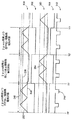
[00104]次に図3Aを参照すると、一連のグラフが示されている。個々のグラフでは、横軸は時間を表しており、また、縦軸は電圧を表している。一実施形態では、グラフ300、302および304は、サブ回路212に関連させることができる。グラフ300は、制御信号232(すなわちコンデンサ228の両端間の電圧)を表すことができ、グラフ302はリセット信号217を表すことができ、また、グラフ304は、サブ回路212のPWM駆動信号238を表すことができる。また、高電圧閾値248、低電圧閾値246および要求信号236が同じく示されている。
[00104] Referring now to FIG. 3A, a series of graphs is shown. In each graph, the horizontal axis represents time, and the vertical axis represents voltage. In one embodiment,
[00105]時間T0でFET230が開き、コンデンサ228が充電を開始する。これにより、時間T0とT2の間のグラフ300の立上り傾斜によって示されているように制御信号232が大きくなる。時間T1で制御信号232(グラフ300)が要求閾値236を横切ると、PWM駆動信号238(グラフ306)がトグルすることになる。時間T2で制御信号232が高電圧閾値248に到達するか、または横切ると、FET230が閉じて、時間T2とT4の間のグラフ300の立下り傾斜によって示されているようにコンデンサが放電を開始する。コンデンサの両端間の電圧が要求信号236に到達するか、または横切ると、時間T3で示されているようにPWM駆動信号238がもう一度トグルすることになる。時間T4で、ノード232の電圧が低電圧閾値246に到達するか、または横切ると、FET230がもう一度開いて、上記サイクルを繰り返すことができる。
[00105] At time T0,
[00106]リセット信号217は、電動機14の位相に対応させることができる。言い換えると、リセット信号217のアサートが解除されると、時間T0で電動機14の特定の位相を開始することができ、また、リセット信号217がアサートされると、時間T5で終了することができる。図3Aに示されているように、時間T5でリセット信号217をアサートする際に、出力信号238はパルスの中間に存在していない。これは、グラフ300が時間T5でPWM駆動信号238上のパルスをトリガしないようにコンデンサ228の充電および放電速度を設定することによって、すなわちグラフ300が立ち上がり、かつ、立ち下がる速さの程度を制御することによって達成することができる。上で言及したように、コンデンサ228の充電および放電速度は、電流制御モジュール250によって制御することができる。
[00106] The
[00107]電動機14の位相の継続期間に対応するようにグラフ300の周波数を設定すると、PWM駆動信号238上の不完全パルス(すなわち短パルス)の発生を少なくするように作用することができる。例えばPWM駆動信号238上のパルスの間にリセット信号217がアサートされると、リセット信号217は、パルスに直ちにアサートを解除させることができ、したがってパルスの長さを短くすることができる。不完全パルスは、それが電動機14へ流れると電動機ジッタの原因になることがあるため、多くの実例において不完全パルスは望ましくない。リセット信号217がアサートされるとパルスが生じないよう、電動機14の位相に対応するように制御信号232の周波数を設定することにより、PWM駆動信号238上の不完全パルスの発生を少なくすることができる。
[00107] Setting the frequency of the
[00108]一実施形態では、制御信号232の周波数または周期は、電動機14の位相の継続期間の倍数にすることができる。例えば図3Aに示されているように、信号232の周波数は、リセット信号217のサイクル毎にほぼ2サイクルが制御信号232上で生じるように設定される。しかしながらこの周波数は、制御信号232の周波数または周期が電動機14の継続期間の任意の倍数になるように設定することも可能である。いくつかの実施形態では、電動機14の位相の間に生じる制御信号232のサイクル数は整数であってもよい。他の実施形態では、電動機14の位相の間に生じる制御信号232のサイクル数は、分数すなわち非整数であってもよい。例えば様々な実施形態では、電動機14のすべての位相に対して、1/7サイクル、1/3サイクル、1/2サイクル、1サイクル、2サイクル、3サイクル、4サイクル、5サイクル、6サイクル、等々のグラフ300を存在させることができる。
[00108] In one embodiment, the frequency or period of the
[00109]一実施形態では、電動機14の位相の継続期間が変化しても、制御信号232のサイクル数は同じサイクル数に維持することができる。例えば信号300のサイクル数は、電動機位相毎に2サイクルであると仮定する。電動機14の速度が速くなると、電動機位相の継続期間はより短くなる。この場合、電流制御モジュール250は、コンデンサがより速く充電および放電され、制御信号232の周波数が高くなり、また、電動機位相毎のサイクル数が2サイクルを維持するよう、コンデンサが充電および放電される速度を修正することができる。電動機14の位相の変化する継続期間に対応するよう、制御信号232の周波数を修正することにより、PWM発生器回路200は、PWM駆動信号238上の不完全パルスの発生を少なくすることができる。
[00109] In one embodiment, the number of cycles of the
[00110]また、図3Aは、サブ回路214に関連させることができる3つのグラフ306、308および310を同じく含む。例えばグラフ306は、コンデンサ252の両端間の電圧(すなわち制御信号254)を表すことができる。グラフ308はリセット信号218を表すことができる。また、グラフ310はPWM駆動信号256を表すことができる。
[00110] FIG. 3A also includes three
[00111]図3Aのリセット信号217および218は、電動機14の位相を表すことができる。例えばリセット信号217(グラフ302)のアサートが解除されているT0とT5の間の時間は、電動機14の第1の位相を表すことができ、また、リセット信号218のアサートが解除されている(グラフ306)T5とT6の間の時間は、電動機14の第2の位相を表すことができる。リセット信号218がもう一度アサートされ、かつ、リセット信号217のアサートがもう一度解除されるT6とT7の間の時間は、電動機14の第3の位相を表すことができる。一実施形態では、電動機14は、電動機14が回転すると繰り返すことができる、1つ、2つ、3つ、4つ、6つ、8つまたは任意の数の位相を有することができる。
[00111] The reset signals 217 and 218 of FIG. 3A may represent the phase of the motor 14. For example, the time between T0 and T5 when the reset signal 217 (graph 302) is deasserted can represent the first phase of the motor 14, and the
[00112]上で言及したように、電動機状態セレクタ回路216は、電動機14の位相に基づいて、動作しているサブ回路とリセット状態にあるサブ回路を交互に切り換えるか、または循環させることができる。図3Aに示されているように、電動機の第1の位相の間は、時間T0とT5の間のPWM駆動信号238上のパルスによって示されているようにサブ回路212が動作しており、サブ回路214はリセット状態にある。電動機の第2の位相の間は、PWM駆動信号256上のパルスによって示されているようにサブ回路212はリセットにあり、サブ回路214が動作している。電動機の第3の位相の間は、時間T6とT7の間のPWM駆動信号238上のパルスによって示されているようにサブ回路212がもう一度動作し、サブ回路214はもう一度リセット状態に置かれる。
[00112] As mentioned above, the motor
[00113]PWM発生器回路200がPWM駆動信号を生成する複数のサブ回路を有している場合、PWM発生器回路200は、電動機14の位相が変化すると、リセット状態に置くサブ回路をこれらのサブ回路の間で交互に切り換えるか、または循環させることができる。図3Aには、2つのサブ回路(すなわちサブ回路212および214)によって生成されるグラフが示されている。しかしながらPWM発生器回路200がもっと多くのサブ回路を有している場合、PWM発生器回路200は、任意の適切な方法または順序でサブ回路をイネーブルおよびディセーブルすることができる。一実施形態では、PWM発生器回路200は、交互方式、ラウンドロビン方式、等々でサブ回路をイネーブルすることができる。
[00113] If the
[00114]PWM駆動信号238および256(および任意の追加サブ回路によって生成される任意のPWM駆動信号)は、結合して、グラフ312によって示されているように不完全パルスを全く含まないPWMドライバ信号210を生成することができる。例えばグラフ312は、PWM駆動信号を結合して結合PWM駆動信号210(図2)を生成するXORゲート260の出力であるPWM駆動信号210を表すことができる。
[00114] The PWM drive signals 238 and 256 (and any PWM drive signals generated by any additional sub-circuits) combine to include a PWM driver that does not include any incomplete pulses as shown by the
[00115]図3Bは、図3Aに示されている波形300、302、306、308および312と同じまたは同様の波形を示したものである。しかしながら電動機位相のタイミングは、図3Bでは若干変化している。電動機14が回転し、かつ、調整されると、電動機の位相の継続期間を若干変化させることができ、したがって電動機の位相の継続期間を変化させることができる。継続期間のこの変化は図3Bに示されている。例えば時間T0’とT1’の間の電動機の位相は、制御信号232の2つのPWMサイクルより若干長くすることができ、時間T1’とT2’の間の電動機の位相は、制御信号232の2つのPWMサイクルに等しくすることができ、また、時間T2’とT3’の間の電動機の位相は、制御信号232の2つのPWMサイクルより若干短くすることができる。
[00115] FIG. 3B shows the same or similar waveforms as the
[00116]電動機14がその最終速度で調整されている場合、電動機位相の継続期間は比較的不変にすることができるが、図3Bに示されているように若干変化させることも可能である。この変化が存在している場合、PWM出力信号210を生成するために使用される信号を切り換えることが場合によっては望ましい。
[00116] If the motor 14 is adjusted at its final speed, the duration of the motor phase can be relatively unchanged, but can also be varied slightly as shown in FIG. 3B. If this change is present, it may be desirable to switch the signal used to generate the
[00117]例えば時間T0’とT1’の間の電動機位相の間、PWM出力信号210上のパルスは制御信号232によって生成することができる。しかしながら図3Bに示されているように、電動機14の位相が変化する時間T1’では、制御信号232は立ち上がることができる。しかしながら制御信号254は、時間T1’まではリセット状態にあり(上で説明したように)、また、時間T1’では、いつでも制御信号254を使用することができる。(言い換えると、制御信号254を生成する回路機構をリセット状態にすることができる)。したがって一実施形態では、PWM発生器回路200は、時間T1’でリセットから制御信号254を取ることができ、したがってそれを使用して、電動機14の第2の位相の間にPWM出力信号210上にパルスを生成することができる。したがってPWM発生器回路200は、電動機14の位相の継続期間が変化しても、電動機14の第2の位相の間に生じるパルスの数を正確に制御することができる。
[00117] For example, during the motor phase between times T0 'and T1', a pulse on the
[00118]同様に、時間T2’で電動機14は第3の電動機位相に入ることができる。時間T2’の前に制御信号254を使用してPWM出力信号210上にパルスを生成することができ、また、制御信号232をリセット状態にしていつでも使用することができる。したがって時間T2’で電動機は制御信号254をリセット状態に置くことができ、また、リセットから制御信号232を取ることができ、したがって制御信号232を使用して、時間T2’とT3’の間にPWM出力信号210上にパルスを生成することができる。
[00118] Similarly, at time T2 ', the motor 14 can enter the third motor phase. Prior to time T2 ', the
[00119]同様に、時間T3’で電動機14は第4の電動機位相に入ることができる。時間T3’の前に制御信号232を使用してPWM出力信号210上にパルスを生成することができ、また、制御信号254をリセット状態にしていつでも使用することができる。電動機位相の継続期間の変化のため、制御信号254は、電動機14が第4の位相に入る時間T3’で立ち下がることができる。したがって時間T3’で電動機は制御信号254をリセット状態に置くことができ、また、リセットから制御信号232を取ることができ、したがって制御信号232を使用して、時間T2’とT3’の間にPWM出力信号210上にパルスを生成することができる。
[00119] Similarly, at time T3 ', motor 14 can enter the fourth motor phase. Prior to time T3 ', the
[00120]次に図4を参照すると、PWM発生器回路34(図1)と同じであるか、または類似していてもよいPWM発生器回路400の一実施形態が示されている。PWM発生器回路200とは対照的に、制御信号発生回路400は、PWM駆動信号402を生成するためのハードウェアの量を少なくしている。例えば図2のPWM発生器回路200は、第1のPWM信号238および第2のPWM信号256を生成するために、コンデンサ、電流源、比較器、等々を含む冗長サブ回路214および214を使用している。これらの信号238および256は、次に、PWM出力信号210を生成するためにXORゲート260によって結合される。
[00120] Referring now to FIG. 4, one embodiment of a
[00121]PWM駆動信号402を生成するために冗長サブ回路を使用する代わりに、PWM発生器回路400は、PWM出力信号402を生成するための複数のコンデンサ(すなわち図4のC1およびC2)および一連のスイッチを使用することができる電流制御モジュール404を使用している。電動機14の位相は変化すると、PWM発生器回路400はスイッチを開閉し、それにより電動機14のいくつかの位相の間、PWM出力信号402を生成するためにコンデンサC1が充電および放電され、また、PWM出力信号402を生成するために、電動機14の交互位相でコンデンサC2が充電および放電される。PWM発生器回路400は、他方のコンデンサが使用されている間、一方のコンデンサC1またはC2を効果的にリセット状態に保持することができ、また、必要に応じてそれらを切り換えることができる。これによりPWM発生器回路400は、電動機14の位相が変化すると使用することができる「準備完了」コンデンサを維持することができる。
[00121] Instead of using redundant subcircuits to generate the
[00122]また、PWM発生器回路400は電動機状態セレクタ回路410を含むことも可能であり、この電動機状態セレクタ回路410は、電動機14の位相に基づいてリセット信号414およびリセット信号416を生成することができる。リセット信号414およびリセット信号416は、スイッチSW1、SW2、SW3、SW4およびSW5を制御することができる。これらのスイッチが開閉すると、電流源406、408および409は、発振グラフを生成するためにコンデンサC1およびC2に電流を供給し、かつ、コンデンサC1およびC2から電流を吸い込むことになる。
[00122] The
[00123]一実施形態では、コンデンサC1およびC2を使用してそれらを切り換え、それによりPWM出力信号402を生成するために、PWM発生器回路400は、以下のような切換えシーケンスを使用することができる。
[00123] In one embodiment, to switch between capacitors C1 and C2, thereby generating
・電動機14の第1の位相の間、信号Reset1はロー状態で開始することができ、また、信号Reset2はハイ状態で開始することができる。これらの状態の間、スイッチSW2、SW3、SW4およびSW5は、コンデンサC2が電流源406および408から開放され、かつ、電流シンク409によって放電されるように構成され、また、コンデンサC1が電流源406および408によって充電および放電されるように構成される。
-During the first phase of the motor 14, the signal Reset1 can start in the low state and the signal Reset2 can start in the high state. During these states, the switches SW2, SW3, SW4 and SW5 are configured such that the capacitor C2 is released from the
・コンデンサC1の電圧がvhigh信号より高い場合、フリップフロップ418の出力がトグルしてスイッチSW1を閉じ、それによりコンデンサC1が放電する。
If the voltage on the capacitor C1 is higher than the vhigh signal, the output of the flip-
・コンデンサC1の電圧がvlow信号より低い場合、フリップフロップ418の出力がトグルしてスイッチSW1を開き、それにより電流源406によってコンデンサC1が充電される。
If the voltage on capacitor C1 is lower than the vlow signal, the output of flip-
・電動機14の位相が変化すると、電動機状態セレクタ410は、信号Reset1をハイ状態に置き、かつ、信号Reset2をロー状態に置く。これらの状態にある間、スイッチSW2、SW3、SW4およびSW5は、コンデンサC1を開放して放電させ、一方、電流源406および408によるコンデンサC2の充電および放電を許容するように構成される。
When the phase of the motor 14 changes, the
・コンデンサC2の電圧がvhigh信号より高い場合、フリップフロップ418の出力がトグルしてSW1を閉じ、それによりコンデンサC2が放電する。
If the voltage on capacitor C2 is higher than the vhigh signal, the output of flip-
・コンデンサC2の電圧がvlow信号より低い場合、フリップフロップ418の出力がトグルしてスイッチSW1を開き、それにより電流源406によってコンデンサC2が充電される。
If the voltage on capacitor C2 is lower than the vlow signal, the output of flip-
・電動機14の位相が引き続いて変化すると、上で説明したサイクルを継続することができる。 • If the phase of the motor 14 continues to change, the cycle described above can be continued.
[00124]次に図5を参照すると、流れ図は、電動機を駆動するためのプロセス500を示している。プロセス500は、全体として、または部分的に、電子回路100などの電子回路によって実施することができる。また、プロセス500は、全体として、または部分的に、他の回路によって、ソフトウェアによって、回路およびソフトウェアの組合せによって、または当分野における任意の他の適切な手段によって実施することも可能である。
[00124] Referring now to FIG. 5, a flow diagram shows a
[00125]ボックス502によって示されているように、プロセス500は、PWM駆動信号238、PWM駆動信号256、PWM駆動信号210、等々などのPWM駆動信号を生成することができる。また、プロセス500は、ボックス504によって示されているように、PWM駆動信号の周波数を制御するための1つまたは複数の制御信号を生成することも可能である。プロセスの実施形態では、制御信号は、1つまたは複数のサブ回路によって生成することができ、また、プロセス500は、PWM駆動信号の周波数を制御するために使用されるサブ回路を交互に切り換えることができる。プロセス500は、複数のサブ回路を交互に切り換えることができ、また、ラウンドロビンなどのスケジューリングスキーム、または電動機14を駆動するための任意の他のスキームを使用することができる。一実施形態では、プロセス500は、電動機14の位相が変化すると、ボックス506によって示されているように、PWM駆動信号の周波数を制御するサブ回路を切り換えることができる。
[00125] As indicated by
[00126]また、プロセス500は、ボックス508によって示されているように、電動機の位相の継続期間を監視することも可能である。継続期間を監視するために、プロセスは、ボックス510によって示されているように電動機14から逆EMF信号を受け取ることができ、かつ/またはボックス512によって示されているように、センサ(すなわち磁界センサ、レゾルバ、等々)から信号を受け取ることができる。
[00126]
[00127]また、プロセス500は、ボックス514によって示されているように、電動機の位相の継続期間に対応するようにPWM駆動信号の周波数を設定することも可能である。一実施形態では、プロセス500は、回路またはソフトウェアを使用して周波数を直接計算することによって、または上で説明したように発振制御信号を提供することによって周波数を設定することができる。周波数は、電動機14の位相毎にPWM駆動信号上に単一のパルスまたは複数のパルスが生じるように設定することができる。一実施形態では、電動機14の位相の間にPWM駆動信号上に生じるパルスの数は固定数であってもよい。いくつかの実施形態では、電動機14の位相の間にPWM駆動信号上に生じるパルスの数は整数であってもよい。他の実施形態では、電動機14の位相の間にPWM駆動信号上に生じるパルスの数は、可変数および/または非整数であってもよく、また、電動機の位相、電動機に印加される電力の量、電動機の所望の周波数、等々に応答して変更することも可能である。
[00127]
[00128]上で説明したように、PWM出力信号上の不完全パルスの発生を少なくするために、リセット信号がアサートされている間、または電動機14の位相が変化している時間ポイントでは、パルスが生じないようにパルスの周波数を設定することができる。上で説明したように周波数を制御し、また、短パルスの発生を少なくすることにより、電動機ジッタを少なくすることができる。例えば従来の電動機ドライバは、高精度電動機を制御する場合、3%〜6%の電動機ジッタをもたらすことがある。しかしながら本発明の実施形態を使用することにより、高精度電動機を制御する場合の電動機ジッタを、3%以下、2%以下、1%以下、等々に少なくすることができる。本発明の実施形態は、他のタイプの電動機(例えば非精度電動機)と共に使用される場合も同じく電動機ジッタを少なくすることができる。 [00128] As explained above, in order to reduce the occurrence of incomplete pulses on the PWM output signal, at the time points when the reset signal is asserted or when the phase of the motor 14 is changing, The frequency of the pulse can be set so as not to occur. As described above, by controlling the frequency and reducing the occurrence of short pulses, the motor jitter can be reduced. For example, conventional motor drivers may cause 3% to 6% motor jitter when controlling high precision motors. However, by using the embodiment of the present invention, the motor jitter when controlling a high-precision motor can be reduced to 3% or less, 2% or less, 1% or less, and so on. Embodiments of the present invention can also reduce motor jitter when used with other types of motors (eg, non-precision motors).
[00129]以上の説明では、特定の信号は、ディジタル信号またはアナログ信号として説明されているが、これには制限は意図されていないことは当業者には認識されよう。様々な実施形態では、上で説明したディジタル信号は等価アナログ信号に置き換えることができ、また、その逆についても同様である。同様に、ディジタル信号またはアナログ信号を受け取り、または生成するものとして上で説明した構成要素は、アナログ信号、ディジタル信号または他のタイプの信号を受け取り、または生成する等価構成要素に置き換えることができる。 [00129] Although the particular signal has been described as a digital signal or an analog signal in the foregoing description, those skilled in the art will recognize that this is not intended to be limiting. In various embodiments, the digital signals described above can be replaced with equivalent analog signals, and vice versa. Similarly, components described above as receiving or generating digital or analog signals can be replaced by equivalent components that receive or generate analog signals, digital signals, or other types of signals.
[00130]以上、本特許の主題である様々な概念、構造および技法を実例で説明する役割を果たしている様々な実施形態について説明したが、これらの概念、構造および技法を組み込んだ他の実施形態を使用することも可能であることは、当業者には明らかになったことと思われる。したがって本特許の範囲は、説明されている実施形態に限定してはならず、そうではなく、本特許の範囲は、特許請求の範囲の精神および範囲によってのみ制限されるものとする。 [00130] While various embodiments have been described that serve to illustrate various concepts, structures and techniques that are the subject of this patent, other embodiments incorporating these concepts, structures and techniques have been described. It will be apparent to those skilled in the art that it is also possible to use Accordingly, the scope of the patent should not be limited to the embodiments described, but is rather limited by the spirit and scope of the claims.
Claims (22)
電動機への電力を制御するために前記電動機に対するパルス幅変調駆動信号を生成するステップと、
前記パルス幅変調駆動信号の周波数を制御するための制御信号を生成するステップと、
前記電動機の速度を監視するステップと、
前記電動機の速度に基づいて前記制御信号を調整するステップであって、それにより前記パルス幅変調駆動信号の周波数を前記電動機の位相の継続期間に関連する値に設定し、延いては前記駆動信号上の不完全パルスの発生を少なくするステップと、
前記制御信号が閾値を横切ると、前記パルス幅変調駆動信号をトグルすることによってパルス幅変調駆動信号上にパルスを生成するステップをと、
前記電動機が位相を変える毎にサブ回路を交互に切り換えることによって、2つ以上のサブ回路によって交互にパルスを生成するステップと、
を含む方法。 A method of driving an electric motor,
Generating a pulse width modulated drive signal for the motor to control power to the motor;
Generating a control signal for controlling the frequency of the pulse width modulation drive signal;
Monitoring the speed of the motor;
A step of adjusting said control signal based on the velocity of the motor, thereby to set the frequency of the pulse width modulated drive signal to a value related to the duration of the motor phase, the by extension Reducing the occurrence of incomplete pulses on the drive signal;
Generating a pulse on the pulse width modulated drive signal by toggling the pulse width modulated drive signal when the control signal crosses a threshold;
Alternately generating pulses by two or more subcircuits by alternately switching subcircuits each time the motor changes phase;
Including methods.
前記電動機の位相が変化すると、前記パルス幅変調駆動信号上に前記パルスを生成するために使用される制御信号を交互に切り換えるステップと
をさらに含む、請求項1〜4のいずれか一項に記載の方法。 Generating one or more additional control signals for generating pulses on the pulse width modulated drive signal;
When position phase of the motor is changed, further comprising the step of alternately switching the control signal used for generating the pulse to the pulse width modulated drive signal on, in any one of claims 1-4 The method described.
ホール効果素子
磁気抵抗素子
磁気トランジスタ
のうちの1つまたは複数を備える、請求項8に記載の方法。 The magnetic field sensor is
9. The method of claim 8 , comprising one or more of a Hall effect element, a magnetoresistive element, a magnetic transistor.
制御信号に応答してパルス幅変調駆動信号上にパルスを生成するように構成された駆動信号発生回路と、
前記電動機から整流信号を受け取り、かつ、前記電動機の速度を監視するように結合された検出回路と、
前記パルス幅変調駆動信号の周波数が前記電動機の位相の継続期間に関連し、それにより前記パルス幅変調駆動信号上の不完全パルスの発生が少なくなるよう、前記監視された電動機の速度に応答して前記制御信号を動的に生成するように構成された制御信号発生回路と、
を備える装置において、
前記制御信号発生回路は、前記パルス幅変調駆動信号を生成する2つ以上のサブ回路を含み、前記電動機が位相を変える毎にサブ回路を交互に切り換えることによって、2つ以上のサブ回路によって交互にパルスを生成するように構成されており、
前記駆動信号発生回路が、前記制御信号が閾値を横切ると、前記パルス幅変調駆動信号をトグルすることによって前記パルス幅変調駆動信号上に前記パルスを生成する、
装置。 An apparatus for driving an electric motor,
A drive signal generating circuit configured to generate a pulse on the pulse width modulated drive signal in response to the control signal;
A detection circuit coupled to receive a commutation signal from the motor and monitor the speed of the motor;
The pulse frequency width modulated drive signal related to the duration of the motor phase, whereby said that occurrence of incomplete pulse on a pulse width modulated drive signal is reduced, in response to velocity of said monitored motor A control signal generating circuit configured to dynamically generate the control signal ;
In an apparatus comprising :
The control signal generation circuit includes two or more sub-circuits that generate the pulse width modulation drive signal, and alternately switches the sub-circuits every time the electric motor changes the phase, thereby alternating between the two or more sub-circuits. Are configured to generate pulses,
The drive signal generating circuit generates the pulse on the pulse width modulation drive signal by toggling the pulse width modulation drive signal when the control signal crosses a threshold;
apparatus.
をさらに備え、前記制御信号発生回路が、前記パルス幅変調駆動信号を生成するために使用される制御信号を交互に切り換えるように構成される、請求項11〜15のいずれか一項に記載の装置。 One or more additional PWM generator circuits for generating the pulses on the pulse width modulated drive signal, wherein the control signal generating circuit is used to generate the pulse width modulated drive signal 16. Apparatus according to any one of claims 11 to 15 , configured to alternately switch control signals.
前記電動機からの逆EMF信号
磁界センサによって生成される信号
レゾルバによって生成される信号
のうちの1つである、請求項11〜19のいずれか一項に記載の装置。 The rectified signal is
The apparatus according to any one of claims 11 to 19 , which is one of a back EMF signal from the motor, a signal generated by a magnetic field sensor, and a signal generated by a resolver.
ホール効果素子
磁気抵抗素子
磁気トランジスタ
のうちの1つまたは複数を備える、請求項20に記載の装置。 The magnetic field sensor is
21. The apparatus of claim 20 , comprising one or more of a Hall effect element, a magnetoresistive element, a magnetic transistor.
Applications Claiming Priority (3)
| Application Number | Priority Date | Filing Date | Title |
|---|---|---|---|
| US13/718,549 | 2012-12-18 | ||
| US13/718,549 US9088233B2 (en) | 2012-12-18 | 2012-12-18 | Systems and methods for reduction of motor jitter while driving an electric motor |
| PCT/US2013/070703 WO2014099215A2 (en) | 2012-12-18 | 2013-11-19 | Systems and methods for reduction of motor jitter while driving an electric motor |
Publications (3)
| Publication Number | Publication Date |
|---|---|
| JP2016501509A JP2016501509A (en) | 2016-01-18 |
| JP2016501509A5 JP2016501509A5 (en) | 2017-02-09 |
| JP6158948B2 true JP6158948B2 (en) | 2017-07-05 |
Family
ID=49684097
Family Applications (1)
| Application Number | Title | Priority Date | Filing Date |
|---|---|---|---|
| JP2015549399A Active JP6158948B2 (en) | 2012-12-18 | 2013-11-19 | System and method for reducing motor jitter while driving a motor |
Country Status (4)
| Country | Link |
|---|---|
| US (1) | US9088233B2 (en) |
| JP (1) | JP6158948B2 (en) |
| KR (1) | KR102119422B1 (en) |
| WO (1) | WO2014099215A2 (en) |
Families Citing this family (10)
| Publication number | Priority date | Publication date | Assignee | Title |
|---|---|---|---|---|
| US9479090B2 (en) | 2013-12-20 | 2016-10-25 | Semiconductor Components Industries, Llc | Motor control circuit and method |
| EP3303370A4 (en) | 2015-05-28 | 2019-03-13 | Immunomedics, Inc. | T20 constructs for anti-hiv (human immunodeficiency virus) therapy and/or vaccines |
| US9887653B2 (en) | 2016-05-25 | 2018-02-06 | Allegro Microsystems, Llc | Sensorless brushless direct current (BLDC) motor position control |
| US9843285B1 (en) | 2016-07-22 | 2017-12-12 | Allegro Microsystems, Llc | Digital demodulator for pulse-width modulated (PWM) signals in a motor controller |
| WO2018141394A1 (en) * | 2017-02-03 | 2018-08-09 | Arcelik Anonim Sirketi | Household appliance with brushless dc motor sensorless control scheme |
| US11374513B2 (en) | 2019-01-23 | 2022-06-28 | Allegro Microsystems, Llc | Motor control circuit with degauss filter |
| US11817811B2 (en) | 2019-03-12 | 2023-11-14 | Allegro Microsystems, Llc | Motor controller with power feedback loop |
| US10784810B1 (en) | 2019-04-29 | 2020-09-22 | Allegro Microsystems, Llc | Motor controller with accurate current measurement |
| CN111079289B (en) * | 2019-12-17 | 2024-04-12 | 广州星迪智能光电科技有限公司 | Method for overcoming motor shake |
| US11563397B2 (en) * | 2021-04-08 | 2023-01-24 | Global Mixed-Mode Technology Inc. | Motor controller |
Family Cites Families (9)
| Publication number | Priority date | Publication date | Assignee | Title |
|---|---|---|---|---|
| JPH08331856A (en) * | 1995-05-30 | 1996-12-13 | Toshiba Corp | Power converting apparatus |
| DE69927373D1 (en) | 1999-09-30 | 2005-10-27 | St Microelectronics Srl | Shock-free detection of current or voltage signals on winding operated with pulse-change modulation |
| JP2006081322A (en) * | 2004-09-10 | 2006-03-23 | Nissan Motor Co Ltd | Ac motor control unit |
| JP4589093B2 (en) * | 2004-12-10 | 2010-12-01 | 日立オートモティブシステムズ株式会社 | Synchronous motor driving apparatus and method |
| JP2008236932A (en) * | 2007-03-22 | 2008-10-02 | Rohm Co Ltd | Motor drive device and electrical apparatus using this |
| US7747146B2 (en) | 2007-08-08 | 2010-06-29 | Allegro Microsystems, Inc. | Motor controller having a multifunction port |
| US7590334B2 (en) | 2007-08-08 | 2009-09-15 | Allegro Microsystems, Inc. | Motor controller |
| CN101682285B (en) * | 2008-03-04 | 2013-10-23 | 旭化成微电子株式会社 | Motor control circuit, motor system, and motor control method |
| JP2010035283A (en) * | 2008-07-25 | 2010-02-12 | Denso Corp | Control device of rotating machine and control system of rotating machine |
-
2012
- 2012-12-18 US US13/718,549 patent/US9088233B2/en active Active
-
2013
- 2013-11-19 WO PCT/US2013/070703 patent/WO2014099215A2/en active Application Filing
- 2013-11-19 JP JP2015549399A patent/JP6158948B2/en active Active
- 2013-11-19 KR KR1020157016557A patent/KR102119422B1/en active IP Right Grant
Also Published As
| Publication number | Publication date |
|---|---|
| WO2014099215A3 (en) | 2014-10-23 |
| WO2014099215A2 (en) | 2014-06-26 |
| KR102119422B1 (en) | 2020-06-05 |
| JP2016501509A (en) | 2016-01-18 |
| US20140167666A1 (en) | 2014-06-19 |
| US9088233B2 (en) | 2015-07-21 |
| KR20150097548A (en) | 2015-08-26 |
Similar Documents
| Publication | Publication Date | Title |
|---|---|---|
| JP6158948B2 (en) | System and method for reducing motor jitter while driving a motor | |
| US8638053B2 (en) | Motor control circuit and method that synchronize a speed of an electric motor to an external clock signal | |
| CN110463021B (en) | Method and device for three-phase motor control with error compensation | |
| US7592764B2 (en) | Method and apparatus for driving a DC motor | |
| US20140055064A1 (en) | Systems and Methods for Controlling Motor Speeds | |
| US10348220B2 (en) | Three-phase motor controlling system for data storage device | |
| TWI629867B (en) | Systems and methods for sensing current through a low-side field effect transistor | |
| JP2007116858A (en) | Motor drive device and electronic device using it | |
| US20140062365A1 (en) | Electronic Circuit and Method for Detecting a Zero Current in a Winding of an Electric Motor | |
| EP3460968A1 (en) | Digital control algorithm using only two target voltage thresholds for generating a pulse width modulated signal driving the gate of a power mos to implement a switch mode power supply | |
| JP2016501509A5 (en) | ||
| US20130099704A1 (en) | Motor Control Circuit And Method That Reduce Speed Jitter Of An Electric Motor | |
| CN108233793B (en) | Method and apparatus for motor starting with sinusoidal phase current | |
| TW201816536A (en) | Power converter with predictive pulse width modulator control | |
| JP6429777B2 (en) | Electronic circuit and method for automatically adjusting the phase of a drive signal applied to an electric motor according to zero current detected in the winding of the electric motor and for detecting zero current | |
| KR101271546B1 (en) | Systems and methods for controlling a dc motor | |
| TWI558090B (en) | Control apparatus for removing charging error of a rotor in the dc motor and method thereof | |
| JP7208071B2 (en) | Driving circuit for stepping motor, driving method thereof, and electronic device using the same | |
| Adhul et al. | Control electronics module for flow control valve using FPGA | |
| US11942831B2 (en) | Three-phase BLDC motor driver/controller having diagnostic signal processing | |
| JP6818662B2 (en) | Motor drive control device and motor drive control method | |
| US20190273454A1 (en) | Motor control device and motor drive system | |
| JP7311957B2 (en) | DC motor drive circuit and electronic equipment using the same | |
| JP3081947B2 (en) | Motor control circuit and motor driving device using the same | |
| Morar | Compact and Intelligent Full/Half Five-Phase Stepping Motor Driver |
Legal Events
| Date | Code | Title | Description |
|---|---|---|---|
| A621 | Written request for application examination |
Free format text: JAPANESE INTERMEDIATE CODE: A621 Effective date: 20151130 |
|
| A131 | Notification of reasons for refusal |
Free format text: JAPANESE INTERMEDIATE CODE: A131 Effective date: 20160921 |
|
| A977 | Report on retrieval |
Free format text: JAPANESE INTERMEDIATE CODE: A971007 Effective date: 20160921 |
|
| A524 | Written submission of copy of amendment under article 19 pct |
Free format text: JAPANESE INTERMEDIATE CODE: A524 Effective date: 20161219 |
|
| TRDD | Decision of grant or rejection written | ||
| A01 | Written decision to grant a patent or to grant a registration (utility model) |
Free format text: JAPANESE INTERMEDIATE CODE: A01 Effective date: 20170510 |
|
| A61 | First payment of annual fees (during grant procedure) |
Free format text: JAPANESE INTERMEDIATE CODE: A61 Effective date: 20170608 |
|
| R150 | Certificate of patent or registration of utility model |
Ref document number: 6158948 Country of ref document: JP Free format text: JAPANESE INTERMEDIATE CODE: R150 |
|
| S531 | Written request for registration of change of domicile |
Free format text: JAPANESE INTERMEDIATE CODE: R313531 |
|
| R350 | Written notification of registration of transfer |
Free format text: JAPANESE INTERMEDIATE CODE: R350 |
|
| R250 | Receipt of annual fees |
Free format text: JAPANESE INTERMEDIATE CODE: R250 |
|
| R250 | Receipt of annual fees |
Free format text: JAPANESE INTERMEDIATE CODE: R250 |
|
| R250 | Receipt of annual fees |
Free format text: JAPANESE INTERMEDIATE CODE: R250 |
|
| R250 | Receipt of annual fees |
Free format text: JAPANESE INTERMEDIATE CODE: R250 |