JP6158618B2 - Ring assembly measuring apparatus, ring assembly measuring method, and rotating machine manufacturing method - Google Patents
Ring assembly measuring apparatus, ring assembly measuring method, and rotating machine manufacturing method Download PDFInfo
- Publication number
- JP6158618B2 JP6158618B2 JP2013147520A JP2013147520A JP6158618B2 JP 6158618 B2 JP6158618 B2 JP 6158618B2 JP 2013147520 A JP2013147520 A JP 2013147520A JP 2013147520 A JP2013147520 A JP 2013147520A JP 6158618 B2 JP6158618 B2 JP 6158618B2
- Authority
- JP
- Japan
- Prior art keywords
- annular
- measuring
- circumferential direction
- base portion
- assembled
- Prior art date
- Legal status (The legal status is an assumption and is not a legal conclusion. Google has not performed a legal analysis and makes no representation as to the accuracy of the status listed.)
- Active
Links
Images


Classifications
-
- G—PHYSICS
- G01—MEASURING; TESTING
- G01B—MEASURING LENGTH, THICKNESS OR SIMILAR LINEAR DIMENSIONS; MEASURING ANGLES; MEASURING AREAS; MEASURING IRREGULARITIES OF SURFACES OR CONTOURS
- G01B5/00—Measuring arrangements characterised by the use of mechanical techniques
- G01B5/14—Measuring arrangements characterised by the use of mechanical techniques for measuring distance or clearance between spaced objects or spaced apertures
-
- F—MECHANICAL ENGINEERING; LIGHTING; HEATING; WEAPONS; BLASTING
- F01—MACHINES OR ENGINES IN GENERAL; ENGINE PLANTS IN GENERAL; STEAM ENGINES
- F01D—NON-POSITIVE DISPLACEMENT MACHINES OR ENGINES, e.g. STEAM TURBINES
- F01D11/00—Preventing or minimising internal leakage of working-fluid, e.g. between stages
- F01D11/001—Preventing or minimising internal leakage of working-fluid, e.g. between stages for sealing space between stator blade and rotor
-
- F—MECHANICAL ENGINEERING; LIGHTING; HEATING; WEAPONS; BLASTING
- F01—MACHINES OR ENGINES IN GENERAL; ENGINE PLANTS IN GENERAL; STEAM ENGINES
- F01D—NON-POSITIVE DISPLACEMENT MACHINES OR ENGINES, e.g. STEAM TURBINES
- F01D25/00—Component parts, details, or accessories, not provided for in, or of interest apart from, other groups
- F01D25/28—Supporting or mounting arrangements, e.g. for turbine casing
- F01D25/285—Temporary support structures, e.g. for testing, assembling, installing, repairing; Assembly methods using such structures
-
- G—PHYSICS
- G01—MEASURING; TESTING
- G01B—MEASURING LENGTH, THICKNESS OR SIMILAR LINEAR DIMENSIONS; MEASURING ANGLES; MEASURING AREAS; MEASURING IRREGULARITIES OF SURFACES OR CONTOURS
- G01B5/00—Measuring arrangements characterised by the use of mechanical techniques
- G01B5/20—Measuring arrangements characterised by the use of mechanical techniques for measuring contours or curvatures
-
- G—PHYSICS
- G01—MEASURING; TESTING
- G01M—TESTING STATIC OR DYNAMIC BALANCE OF MACHINES OR STRUCTURES; TESTING OF STRUCTURES OR APPARATUS, NOT OTHERWISE PROVIDED FOR
- G01M15/00—Testing of engines
- G01M15/14—Testing gas-turbine engines or jet-propulsion engines
Landscapes
- Engineering & Computer Science (AREA)
- Physics & Mathematics (AREA)
- General Physics & Mathematics (AREA)
- Mechanical Engineering (AREA)
- General Engineering & Computer Science (AREA)
- Chemical & Material Sciences (AREA)
- Combustion & Propulsion (AREA)
- A Measuring Device Byusing Mechanical Method (AREA)
- Turbine Rotor Nozzle Sealing (AREA)
- Length Measuring Devices With Unspecified Measuring Means (AREA)
Description
本発明は、例えば、タービンの翼環と支持環とを有する環状組立体の測定装置、環状組立体の測定方法、及び回転機械の製造方法に関する。 The present invention relates to, for example, an apparatus for measuring an annular assembly having a blade ring and a support ring of a turbine, an annular assembly measuring method, and a rotating machine manufacturing method.
タービンの製造工程、又はタービンのメンテナンス(例えば、翼環を構成する静翼の交換作業)における組み立て作業時においては、静翼を保持する翼環と、静翼の内周側に固定されシールリングを保持する保持環とからなる環状組立体の組み立て精度が重要である。 At the time of assembling work in the turbine manufacturing process or turbine maintenance (for example, replacement work of a stationary blade constituting the blade ring), the blade ring that holds the stationary blade and the seal ring that is fixed to the inner peripheral side of the stationary blade The assembly accuracy of the annular assembly composed of the retaining ring for holding the is important.
これらの作業時では、環状組立体の測定装置を用いて、翼環と保持環との位置決め(芯出し)作業が行われる。このとき、翼環と保持環との位置決めが不適切であると、シールリングとシールフィンとの隙間が不適切となり十分なシール性が得らない。また、シールリングの偏心によりロータ回転時にラビング(タービン回転部と静止部との接触)が発生するおそれがある。 During these operations, a positioning (centering) operation of the blade ring and the holding ring is performed using the measurement device for the annular assembly. At this time, if the positioning of the blade ring and the holding ring is inappropriate, the gap between the seal ring and the seal fin becomes inappropriate and sufficient sealing performance cannot be obtained. Further, rubbing (contact between the turbine rotating portion and the stationary portion) may occur during rotation of the rotor due to the eccentricity of the seal ring.
従来の環状組立体の測定装置としては、例えば特許文献1に記載されたものがある。従来例図6に示すように、この測定装置101は、翼環61、保持環62、及び静翼63を有する環状組立体60において、翼環61に対する保持環62の径方向の相対位置を測定することにより、翼環61に対する保持環62の組立精度を確保する装置である。
測定装置101を用いた位置決め作業においては、翼環61側の基準点と保持環62側の計測点との距離が翼環61上の複数点にて計測され、この計測値に基づいて翼環61に対する保持環62の取り付け位置が微調整される。
As a conventional measuring apparatus for an annular assembly, for example, there is one described in Patent Document 1. As shown in FIG. 6, the
In the positioning operation using the
測定装置101は、ベース部106と、シャフト部107と、プローブ部108と、を有する。計測時において、ベース部106は翼環61の外周側縁部61aに配置され、翼環61側の基準点を規定する。シャフト部107は、ベース部106に固定されて設置され、計測時に翼環61の径方向内側に延出する。プローブ部108は、シャフト部107の先端に取り付けられたダイヤルゲージ28を有し、保持環62側の計測点を規定する。
The
ところで、この従来の測定装置101では、ベース部106の複数のベース脚113を翼環61の外周側縁部61aに当接させつつ、ベース部106の側部下方に配置されたガイドローラ124を翼環61の外周面61bに当接させて、ベース部106の基準点を規定している。即ち、翼環61の外周面61bが測定装置101における翼環径方向の基準面である。
しかしながら、このような方法で基準点を規定する場合、ガイドローラ124を基準面である外周面61bに対して所定の押圧力で当接させることが難しく、基準面に対するベース部106の位置が安定しないため、計測精度が高くないという課題があった。
By the way, in this conventional
However, when the reference point is defined by such a method, it is difficult to bring the
この発明は、このような事情を考慮してなされたもので、その目的は、環状部材に周方向に複数並ぶ被組立部材を組み立てた環状組立体における環状部材に対する被組立部材の径方向の相対位置を測定する際の精度を高めることができる環状組立体の測定装置を提供することにある。 The present invention has been made in consideration of such circumstances, and an object of the present invention is to provide a relative relationship in the radial direction of the member to be assembled with respect to the annular member in the annular assembly in which a plurality of members to be assembled are arranged in the circumferential direction on the annular member. An object of the present invention is to provide an annular assembly measuring apparatus capable of increasing the accuracy in measuring the position.
上記の目的を達成するために、この発明は以下の手段を提供している。
本発明は、環状部材に、周方向に複数並ぶ被組立部材を組み立てた環状組立体における前記環状部材に対する前記被組立部材の径方向の相対位置を測定する環状組立体の測定装置であって、前記環状部材の周方向に連続する基準面に当接し、前記基準面に沿って周方向に移動可能な第一当接部と、前記環状部材の前記基準面と径方向反対側に向く対向面を押圧可能で、径方向に位置調整可能な第二当接部と、前記第一当接部及び前記第二当接部を支持するベース部と、前記被組立部材の被測定部に当接する第三当接部と、前記第三当接部と前記ベース部とを連結する連結部と、前記ベース部に対する前記第三当接部の変位を測定する測定部とを備え、前記基準面と前記対向面とは対向して配置され、前記第一当接部は、周方向に互いに離間して配置された一対のブロック状部材であり、前記第二当接部は、前記一対のブロック状部材の間の周方向中央に配置されることを特徴とする。
In order to achieve the above object, the present invention provides the following means.
The present invention is a measuring apparatus for an annular assembly for measuring a relative position in a radial direction of the member to be assembled with respect to the annular member in an annular assembly in which a plurality of members to be assembled arranged in the circumferential direction are assembled on the annular member, A first abutting portion that is in contact with a reference surface continuous in the circumferential direction of the annular member and is movable in the circumferential direction along the reference surface; and an opposing surface facing the reference surface of the annular member in a radial direction opposite to the reference surface A second abutting portion that can be pressed in a radial direction, a base portion that supports the first abutting portion and the second abutting portion, and a to-be-measured portion of the assembly target member a third contact portion, wherein the third contact portion and the connecting portion connecting the base portion, and a measuring section for measuring the displacement of the third contact portion relative to the base portion, and the reference plane The first contact portions are disposed opposite to the facing surface, and are spaced apart from each other in the circumferential direction. A pair of block-like member disposed, the second contact portion, characterized in that it is arranged in the circumferential center between the pair of block-shaped member.
上記構成によれば、第二当接部が対向面を押圧することで第一当接部が基準面に所定の押圧力で当接する。これにより基準面に対するベース部の位置が安定するため、ベース部に対する第三当接部の変位を測定する際の精度を高めることができる。即ち、環状組立体における環状部材に対する被組立部材の径方向の相対位置を測定する際の精度を高めることができる。 According to the said structure, a 1st contact part contact | abuts to a reference surface with predetermined | prescribed pressing force because a 2nd contact part presses an opposing surface. As a result, the position of the base portion with respect to the reference surface is stabilized, so that the accuracy in measuring the displacement of the third contact portion with respect to the base portion can be increased. That is, it is possible to increase the accuracy when measuring the relative position in the radial direction of the member to be assembled with respect to the annular member in the annular assembly.
上記環状組立体の測定装置において、前記第二当接部は、前記対向面を周方向に転動可能な球形状をなしていることが好ましい。 In the measurement apparatus of the annular assembly, said second contact portion is preferably forms a rollable spherical shape said opposed surfaces in the circumferential direction.
上記構成によれば、基準面に対するベース部の位置が保持された状態で測定装置を周方向に移動させることができるため、ベース部に対する第三当接部の変位の変化を高精度に計測することができる。 According to the above configuration, since the measuring device can be moved in the circumferential direction while the position of the base portion with respect to the reference surface is held, the change in displacement of the third contact portion with respect to the base portion is measured with high accuracy. be able to.
上記環状組立体の測定装置において、前記基準面及び前記対向面は、前記環状部材の径方向内側に形成された溝を構成する互いに対向する径方向両側に設けられた面であり、前記ベース部は、前記第一当接部を有して前記溝に挿入されるブロック状の被嵌合部材と、前記第二当接部を有するガイドローラと、を備えることが好ましい。 In the measurement apparatus for an annular assembly, the reference surface and the facing surface are surfaces provided on opposite radial sides constituting a groove formed on the radially inner side of the annular member, and the base portion. It is preferable to include a block-like mating member that has the first contact portion and is inserted into the groove, and a guide roller that has the second contact portion.
上記構成によれば、環状部材の鉛直方向上方に突起物がある場合においても、測定装置のベース部を環状部材に固定することができる。また、被係合部材を溝に沿ってスライドさせることによって、容易にベース部と環状部材とを固定することができる。 According to the above configuration, the base portion of the measuring device can be fixed to the annular member even when there is a protrusion above the annular member in the vertical direction. Moreover, the base part and the annular member can be easily fixed by sliding the engaged member along the groove.
上記環状組立体の測定装置において、前記環状部材は、タービンの翼環であり、前記溝は、前記タービンの遮熱環の固定に用いられる溝であることが好ましい。 In the annular assembly measuring apparatus, it is preferable that the annular member is a turbine blade ring, and the groove is a groove used for fixing a heat shield ring of the turbine.
上記構成によれば、ベース部を固定するための溝を新たに加工することなく、ベース部を環状部材に固定することができる。 According to the said structure, a base part can be fixed to a cyclic | annular member, without processing the groove | channel for fixing a base part newly.
上記環状組立体の測定装置において、前記ベース部は、前記環状部材の中心軸方向一方側に配置されており、前記連結部から中心軸方向他方側に延在し、その先端を前記被組立部材の中心軸方向一方側を向く面に当接させることによって、前記連結部を支持する支持部材を有することが好ましい。 In the annular assembly measuring apparatus, the base portion is disposed on one side in the central axis direction of the annular member, extends from the coupling portion to the other side in the central axis direction, and a tip of the base portion is the assembly target member. It is preferable to have a support member that supports the connecting portion by contacting with a surface facing one side in the central axis direction.
上記構成によれば、連結部がベース部の径方向内側に延在し、剛性が不足している場合においても、第三当接部の位置を安定させることができる。 According to the said structure, the position of a 3rd contact part can be stabilized even when a connection part is extended to the radial inside of a base part, and rigidity is insufficient.
また、本発明は、環状部材に、周方向に複数並ぶ被組立部材を組み立てた環状組立体における前記環状部材に対する前記被組立部材の径方向の相対位置を測定する環状組立体の測定方法であって、前記環状部材の周方向に連続する基準面に、測定装置のベース部の第一当接部を当接させるとともに、前記環状部材の前記基準面と径方向反対側を向く対向面に、測定装置のベース部の第二当接部を押圧させるベース部配置工程と、前記ベース部と連結されている第三当接部を、前記被組立部材の被測定部に当接させる被測定部当接工程と、前記第一当接部が前記基準面に当接されたまま、前記基準面に沿って周方向に前記ベース部を移動させつつ、前記ベース部に対する前記第三当接部の径方向の変位を測定する変位測定工程と、を備え、前記基準面と前記対向面とは対向して配置されており、前記第一当接部は、周方向に互いに離間して配置された一対のブロック状部材であり、前記第二当接部は、前記一対のブロック状部材の間の周方向中央に配置される環状組立体の測定方法を提供する。 In addition, the present invention is a measurement method of an annular assembly that measures a relative position in a radial direction of the member to be assembled with respect to the annular member in an annular assembly in which a plurality of members to be assembled arranged in the circumferential direction are assembled on the annular member. Then, the first contact portion of the base portion of the measuring device is brought into contact with the reference surface continuous in the circumferential direction of the annular member, and the opposite surface facing the reference surface of the annular member in the radial direction, A base portion arranging step for pressing the second contact portion of the base portion of the measuring device, and a measured portion for bringing the third contact portion connected to the base portion into contact with the measured portion of the member to be assembled The abutting step and the third abutting portion with respect to the base portion while moving the base portion in the circumferential direction along the reference surface while the first abutting portion is in contact with the reference surface. comprising a displacement measuring step of measuring the radial displacement, the said The quasi-surface and the opposing surface are arranged to face each other, the first contact portion is a pair of block-like members that are spaced apart from each other in the circumferential direction, and the second contact portion is Provided is a method for measuring an annular assembly disposed at the center in the circumferential direction between the pair of block-shaped members .
上記構成によれば、第二当接部が対向面を押圧することで第一当接部が基準面に所定の押圧力で当接する。これにより基準面に対するベース部の位置が安定するため、ベース部に対する第三当接部の変位を測定する際の精度を高めることができる。即ち、環状組立体を構成する環状部材と被組立部材の芯精度を測定する際の精度を高めることができる。 According to the said structure, a 1st contact part contact | abuts to a reference surface with predetermined | prescribed pressing force because a 2nd contact part presses an opposing surface. As a result, the position of the base portion with respect to the reference surface is stabilized, so that the accuracy in measuring the displacement of the third contact portion with respect to the base portion can be increased. That is, the accuracy in measuring the core accuracy of the annular member constituting the annular assembly and the member to be assembled can be increased.
上記環状組立体の測定方法において、前記ベース部配置工程では、前記環状部材に形成された溝の互いに対向する径方向両側の面を前記基準面及び前記対向面として、前記第一当接部を有する前記ベース部の被嵌合部材を前記溝に挿入し、前記変位測定工程では、前記被嵌合部材を前記溝の内部で移動させることが好ましい。 In the measurement method of the annular assembly, in the base portion disposing step, the first abutting portion is formed with the surfaces on both sides in the radial direction facing each other of the groove formed in the annular member as the reference surface and the facing surface. It is preferable that the member to be fitted of the base portion is inserted into the groove, and in the displacement measuring step, the member to be fitted is moved inside the groove.
上記構成によれば、環状部材の鉛直方向上方に突起物がある場合においても、測定装置のベース部を環状部材に固定することができる。また、被係合部材を溝に沿ってスライドさせることによって、容易にベース部と環状部材とを固定することができる。 According to the above configuration, the base portion of the measuring device can be fixed to the annular member even when there is a protrusion above the annular member in the vertical direction. Moreover, the base part and the annular member can be easily fixed by sliding the engaged member along the groove.
また、本発明は、環状部材に、被組立部材を周方向に複数並べるように組み立てる環状組立体組立工程と、上記環状組立体の測定方法により、前記環状部材に対する前記被組立部材の径方向の相対位置を測定する測定工程と、前記測定工程による測定結果に基づいて前記環状部材に対する前記被組立部材の組立精度が確保された前記環状組立体をケーシングに組み立てる環状組立体取付工程とを備える回転機械の製造方法を提供する。
Further, the present invention is in the ring-shaped member, and the annular assembly assembling process of assembling as arranging a plurality of the assembly member in the circumferential direction, the measurement method of the annular assembly, the radial direction of the object to be assembled member with respect to the annular member A measuring step for measuring the relative position of the ring member, and an annular assembly attaching step for assembling the annular assembly in which the assembly accuracy of the assembly target member with respect to the annular member is ensured based on the measurement result of the measuring step. A method of manufacturing a rotating machine is provided.
本発明によれば、環状部材に周方向に複数並ぶ被組立部材を組み立てた環状組立体において、環状部材に対する被組立部材の径方向の相対位置を測定する際の精度を高めることができる。 ADVANTAGE OF THE INVENTION According to this invention, the precision at the time of measuring the relative position of the to-be-assembled member's radial direction with respect to an annular member can be improved in the annular assembly which assembled the to-be-assembled member arranged in the circumferential direction on the annular member.
以下、本発明の実施形態について図面を参照して詳細に説明する。
本実施形態の環状組立体の測定装置は、例えば、メンテナンスなどによるタービンの再組立時において、タービンの翼環とシールリングの保持環との位置決め(芯出し)を行うために用いられる治具である。
翼環と保持環の位置決めは、環状部材である翼環に被組立部材である保持環を組み立てた環状組立体において、翼環に対する保持環の径方向の相対位置を測定し、この測定結果に基づいて組み立て精度(芯精度)を確保することによって行われる。
Hereinafter, embodiments of the present invention will be described in detail with reference to the drawings.
The annular assembly measuring apparatus of the present embodiment is a jig used for positioning (centering) the turbine blade ring and the seal ring holding ring when the turbine is reassembled due to maintenance, for example. is there.
The positioning of the blade ring and the retaining ring is performed by measuring the relative position of the retaining ring in the radial direction with respect to the blade ring in an annular assembly in which the retaining ring as the assembly target member is assembled to the blade ring as the annular member. This is done by ensuring assembly accuracy (core accuracy).
まず、翼環を備えている回転機械であるガスタービンについて説明する。
図1に示すように、ガスタービン50は、外気を圧縮して圧縮空気を生成する圧縮機51と、燃料供給源からの燃料を圧縮空気に混合して燃焼させ燃焼ガスを生成する燃焼器52と、燃焼ガスにより駆動するタービン53と、を備えている。
First, a gas turbine that is a rotary machine including a blade ring will be described.
As shown in FIG. 1, a
タービン53は、回転機械で、軸線Arを中心として回転するタービンロータ54と、このタービンロータ54を回転可能に覆うタービンケーシング55(ケーシング)と、を有している。また、圧縮機51も、回転機械で、前述の軸線Arを中心として回転する圧縮機ロータ56と、この圧縮機ロータ56を回転可能に覆う圧縮機ケーシング57と、を有している。
The
このガスタービン50は、さらに、圧縮機ロータ56のタービン53側及びタービンロータ54の圧縮機51側を覆う圧縮機兼タービンケーシング58を有している。圧縮機ケーシング57、タービンケーシング55、及び圧縮機兼タービンケーシング58は、いずれも、軸線Arを中心として筒状を成している。タービンロータ54と圧縮機ロータ56とは、相互に連結され、軸線Arを中心として一体回転する。
The
タービンケーシング55の内周側には、軸線Arを中心として環状を成す複数の環状組立体60が軸方向に並んで設けられている。環状組立体60は、本実施形態の測定装置1の測定対象である翼環61(図2参照)と保持環62(図2参照)とを有している。各環状組立体60は、いずれも、組立の都合上、周方向に分割可能である。
On the inner peripheral side of the
次に、測定対象である翼環61と保持環62を有する環状組立体60について説明する。
図2に示すように、環状組立体60は、複数の要素からなる環状部材である翼環61と、翼環61の内周側に周方向に取り付けられた複数の静翼63と、静翼63の内周側に設けられた内側シュラウド64と、内側シュラウド64のフランジに固定された保持環62と、保持環62により保持されたシールリング65と、を有している。
Next, the
As shown in FIG. 2, the
保持環62は、環状部材に静翼63などを介して周方向に複数並んで組み立てられた被組立部材である。複数の静翼63は、タービン53のタービンロータ54(図1参照)周囲の静止側に設けられてタービン53のガス流路を形成し、タービンロータ54側に取り付けられた動翼と組みになって段を構成する。
The retaining
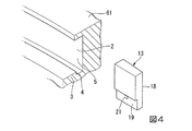
本実施形態の翼環61には、遮熱環67を取り付けるための複数の嵌合溝2,2aが形成されている。嵌合溝2,2aは、翼環61の径方向(以下、単に径方向と呼ぶ)内側に、翼環61の周方向に連続して形成されている。複数の嵌合溝2,2aのうちの少なくとも二つの嵌合溝2aに嵌合する遮熱環67は、静翼63を固定するために使用されている。
A plurality of
本実施形態の測定装置1は、別の一つの嵌合溝2に取り付けられて使用される。嵌合溝2は、機械加工によって、周方向からみた断面形状が一様となるように形成されている。具体的には、嵌合溝2の断面形状は、図5にも示すように、径方向内周側が開放された矩形状をなしており、嵌合溝2に遮熱環67が取り付けられる際には、遮熱環67を保持する突条3を有している。
The measuring device 1 of this embodiment is used by being attached to another one
嵌合溝2は、この突条3の径方向外側の面であって、径方向外側を向く基準面4を有している。基準面4は、測定装置1を用いて環状組立体60の芯精度を測定する際に、翼環61側の基準点となる面である。基準面4は周方向に延在して、翼環61を一周するように形成されている。
嵌合溝2は、機械加工によって形成された溝である。故に、基準面4は機械加工によって形成された加工面であり、精度が確保されて形成されている。
The
The
また、嵌合溝2は、径方向における基準面4と反対側を向く面、即ち、径方向内側を向く面となる対向面5を有している。換言すれば、基準面4と対向面5とは、互いに対向する径方向両側に設けられた面である。対向面5も基準面4と同様に周方向に延在して、翼環61を一周するように形成されている。
また、本実施形態の翼環61の外周側縁部61aには、突起物68が設けられている。即ち、本実施形態の翼環61の外周側縁部61aは平坦とはされていない。
Further, the
Further, a
次に、測定装置1の詳細について説明する。
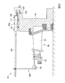
図2、及び図3に示すように、測定装置1は、板形状のベース部6と、ベース部6に取り付けられた棒形状のシャフト部7と、シャフト部7の先端側(翼環61の径方向内側)に取り付けられたプローブ部8と、データ処理部(図示せず)と、を有している。シャフト部7は、プローブ部8とベース部6とを連結する連結部として機能する。
Next, details of the measuring apparatus 1 will be described.
As shown in FIG. 2 and FIG. 3, the measuring device 1 includes a plate-shaped
ベース部6は、翼環61側の基準となる部位である。ベース部6は、板形状のベースプレート12と、ベースプレート12に取り付けられ、嵌合溝2に嵌合することでベース部6を翼環61に保持させる一対の被嵌合部材13と、ボールキャスターからなるガイドローラ24と、を有している。
The
ベースプレート12は、等脚台形形状の板状部材であり、ベース部6が翼環61に取り付けられた際に上方を向く上面14と、下方を向く下面15と、等脚台形の下辺に相当する位置で、上面14及び下面15に直交する面である接続面16と、を有している。ベースプレート12は、上面14及び下面15が翼環61の軸線に直交し、かつ、接続面16が翼環61の内周側の面に沿い、かつ、台形の上辺に相当する辺が翼環61の中心に向くように配置される。
The
図4に示すように、被嵌合部材13は、周方向に延在する嵌合溝2にスライドさせつつ嵌合させることが可能な略直方体形状のブロック状部材である。被嵌合部材13は、嵌合溝2の対向面5に沿うように形成された背面18と、背面18の反対側に形成され、嵌合溝2の基準面4に沿うように形成された基準当接面19(第一当接部)とを有している。背面18と基準当接面19とは、翼環61の内周側の面と略同一の曲率半径を有する湾曲面となっている。また、被嵌合部材13は、例えばアルミニウムなどの金属によって形成されている。
As shown in FIG. 4, the fitted
図3に示すように、被嵌合部材13は、ベースプレート12の接続面16に、例えばボルトのような締結部材20を介して取り付けられている。具体的には、ベースプレート12の接続面16に形成された、ベースプレート12の上面14及び下面15に沿う方向に形成されたネジ穴を用いて取り付けられる。被嵌合部材13側の固定孔21(図4参照)には、被嵌合部材13を固定する締結部材20の頭部が嵌合溝2と干渉しないように、適宜ザグリ加工が施されている。
As shown in FIG. 3, the fitted
シャフト部7は、例えば、アルミニウム製の中空の長尺部材からなり、計測時において、翼環61の径方向内側に延出するようにベース部6に設置される。シャフト部7は、ベース部6に対して長手方向(軸方向)に変位可能に取り付けられている。
シャフト部7は、ベース部6上に固定されているガイド部22に支持されて配置されている。ガイド部22には、ボール軸受が接続されており、これにより、シャフト部7はガイド部22の長手方向に変位可能となっている。
The
The
図5に示すように、ガイドローラ24は、シャフト部7のベース部6側の端部に固定されている。ガイドローラ24は、球形状をなすボール25(第二当接部)がシャフト部7の軸方向に向くように固定されている。ガイドローラ24は、シャフト部7及びガイド部22を介してベースプレート12に支持されている。
As shown in FIG. 5, the
ガイドローラ24のボール25は、嵌合溝2の対向面5に当接するように配置されている。換言すれば、シャフト部7は、シャフト部7の軸線と環状溝の対向面5とが直交するように配置されている。ガイドローラ24には、ガイドローラ24から延在され、外周に雄ネジ溝が形成された固定軸33が設けられている。
ガイドローラ24は、シャフト部7の端部に形成された雌ネジ穴に固定軸33を螺合し、さらに、ナット34によって固定軸33を締結することによって固定されている。ガイドローラ24の径方向位置は、この固定機構により調整することができる。
The
The
図2に示すように、プローブ部8は、計測時において保持環62の内周面に当接して、保持環62の計測点を規定する部位である。プローブ部8は、シャフト部7の先端に所定のジョイント26を介して取り付けられ、シャフト部7と直交して下方に延在するプローブステー27と、プローブステー27の下方に取り付けられた測定部であるダイヤルゲージ28と、を有している。
ダイヤルゲージ28は、測定子29(第三当接部)が保持環62の内周面62a(被測定部)に当接するように固定されている。ダイヤルゲージ28の径方向及び鉛直方向の位置は、ジョイント26によって調整可能である。
As shown in FIG. 2, the
The
また、シャフト部7上であって、プローブ部8とベース部6との間には、シャフト部7を支持する支持部材であるシャフト支持部30が設けられている。シャフト支持部30は、シャフト部7に所定のジョイント26を介して取り付けられ、シャフト部7と直交して下方に延在するステー31と、ステー31の下方に取り付けられたボールキャスター32と、を有している。
ボールキャスター32の径方向及び鉛直方向の位置は、ジョイント26によって調整可能であり、本実施形態の測定装置1においては、ボールキャスター32が、保持環62の上面35に当接するように調節されている。
Further, a
The radial position and the vertical position of the
次に、本実施形態の測定装置1を用いた環状組立体60の測定方法、及び、この測定方法を用いた回転機械の製造方法について説明する。測定装置1は、翼環61を翼環61の軸方向が鉛直方向と沿うように配置した状態で使用される。
Next, a method for measuring the
(環状組立体組立工程)
まず、翼環61に保持環62を周方向に複数並べるように組み立てる。具体的には、翼環61に遮熱環67を用いて静翼63を固定し、静翼63と一体にされた内側シュラウド64のフランジに保持環62を取り付ける。
(Annular assembly assembly process)
First, the
(ベース部配置工程)
次いで、測定装置1を翼環61に取り付ける。具体的には、図4に示すように、被嵌合部材13を嵌合溝2に周方向より挿入する。これにより、図3に示すように、測定装置1のベース部6が翼環61に仮固定される。取り付けの際は、翼環61は分割された状態にあるため、嵌合溝2の端部より被嵌合部材13を挿入することができる。
(Base part placement process)
Next, the measuring device 1 is attached to the
次いで、翼環61を構成する複数の要素を互いに連結させ、環状組立体60を組み立てる。即ち、環状の翼環61(環状部材)の内周側に、静翼63、保持環62(被測定部材)などが組み付けられた状態とする。この環状組立体60が、本実施形態の測定装置1の測定対象となる。なお、環状組立体60は、床面に配置されているが、複数の所定の作業用ブロック上に載置してもよい。
Next, a plurality of elements constituting the
次いで、シャフト支持部30と、プローブ部8の位置の仮調整を行う。具体的には、シャフト支持部30のボールキャスター32が保持環62の上面35の所定に位置に乗り、シャフト部7が略水平となるようにシャフト支持部30の位置調整を行う。また、ダイヤルゲージ28の測定子29が、保持環62の内周面62aに当接するように、プローブ部8の位置調整を行う。
Next, provisional adjustment of the positions of the
次いで、ガイドローラ24のボール25を対向面5に押圧させる。具体的には、ナット34を緩めた状態で、ガイドローラ24の突出量を調整し、ガイドローラ24のボール25が対向面5を十分に押圧させた状態でガイドローラ24の軸方向の位置を固定する。これにより、被嵌合部材13の基準当接面19が、嵌合溝2の基準面4に当接し、翼環61側の基準点が規定される。
Next, the
(被測定部当接工程)
上記ベース部配置工程にてガイドローラ24を固定した後、仮固定されたプローブ部8の測定子29を保持環62の内周面62aに当接させる。そして、仮固定されていたシャフト支持部30とプローブ部8を固定する。
(Measured part contact process)
After the
(変位測定工程)
次いで、この基準となる位置における翼環61に対する保持環62の位置を計測する。具体的には、プローブ部8を構成するダイヤルゲージ28の数値が、データ処理部に転送されて記録される。
次いで、ベース部6を周方向にスライドさせ、基準となる位置以外の各点の計測値を取得する。この際、被嵌合部材13は嵌合溝2の内部で移動し、ガイドローラ24のボール25が対向面5を周方向に転動する。
(Displacement measurement process)
Next, the position of the holding
Next, the
次いで、取得された計測値に基づいて保持環62の位置判定が行われる。例えば、取得された計測値が所定の設定範囲内にある場合には、翼環61と保持環62との位置決めが適正に行われていると判断される。この場合には、測定装置1が撤去されて、位置決め作業が終了する。
一方、取得された計測値が所定の設定範囲内にない場合には、翼環61に対する保持環62の取付位置が微調整される。これにより、翼環61と保持環62とが適正に位置決めされる。なお、この位置決め作業は、タービン53の2段静翼〜4段静翼の各翼環61について行われる。
Next, the position of the holding
On the other hand, when the acquired measurement value is not within the predetermined setting range, the attachment position of the holding
(環状組立体取付工程)
最後に、環状組立体60がタービン53のタービンケーシング55(ケーシング)に組み立てられる。
(Annular assembly mounting process)
Finally, the
上記実施形態によれば、ガイドローラ24が嵌合溝2の対向面5を押圧することで被嵌合部材13の基準当接面19が基準面4に十分に当接する。これにより基準面4に対するベース部6の位置が安定するため、ベース部6に対する測定子29の変位を測定する際の精度を高めることができる。即ち、環状組立体60を構成する翼環61に対する保持環62の径方向の相対位置を測定する際の精度を高めることができる。これにより、翼環61に対する保持環62の組立精度を確保することができる。
According to the above embodiment, the
また、基準面4に対するベース部6の位置が保持された状態で測定装置1を周方向に移動させることができるため、ベース部6に対する測定子29の変位の変化を高精度に計測することができる。
また、嵌合溝2を介して測定装置1を固定することによって、翼環61の鉛直方向上方に突起物68がある場合においても、測定装置1を翼環61に固定することができる。
また、遮熱環67を固定するための嵌合溝2を測定装置1の固定に利用することによって、測定装置1のベース部6を固定するための溝を新たに加工することなく、測定装置1を翼環61に固定することができる。
Further, since the measuring apparatus 1 can be moved in the circumferential direction while the position of the
In addition, by fixing the measuring device 1 via the
Further, by using the
また、シャフト部7にシャフト支持部30を設けたことによって、シャフト部7の剛性が不足している場合においても、ダイヤルゲージ28の測定子29の位置を安定させることができる。
また、被嵌合部材13を嵌合溝2に沿ってスライドさせることによって、容易にベース部6と翼環61とを固定することができる。
Further, by providing the
Further, the
なお、本発明の技術範囲は、上述した各実施形態に限定されるものではなく、本発明の趣旨を逸脱しない範囲において、上述した実施形態に種々の変更を加えたものを含む。すなわち、上述した実施形態で挙げた構成等は一例であり、適宜変更が可能である。
例えば、本実施形態では、タービン53の翼環61と保持環62とを有する環状組立体60を測定対象としたが、これに限ることはなく、環状部材に周方向に複数並ぶ被組立部材を組み立てたものを測定対象とすることができる。
また、ベース部6と翼環61とを接続する被嵌合部材13を2つ設ける構成を示したが、その数は問わない。
The technical scope of the present invention is not limited to the above-described embodiments, and includes those in which various modifications are made to the above-described embodiments without departing from the spirit of the present invention. In other words, the configuration described in the above-described embodiment is an example, and can be appropriately changed.
For example, in the present embodiment, the
Moreover, although the structure provided with the to-
1 測定装置
2 嵌合溝
3 突条
4 基準面
5 対向面
6 ベース部
7 シャフト部(連結部)
8 プローブ部
12 ベースプレート
13 被嵌合部材
14 上面
15 下面
16 接続面
18 背面
19 基準当接面(第一当接部)
20 締結部材
21 固定孔
22 ガイド部
24 ガイドローラ
25 ボール(第二当接部)
26 ジョイント
27 プローブステー
28 ダイヤルゲージ(測定部)
29 測定子(第三当接部)
30 シャフト支持部
31 ステー
32 ボールキャスター
50 ガスタービン
51 圧縮機
52 燃焼器
53 タービン
54 タービンロータ
55 タービンケーシング(ケーシング)
60 環状組立体
61 翼環(環状部材)
62 保持環(被組立部材)
62a 内周面(被測定部)
65 シールリング
67 遮熱環
68 突起物
DESCRIPTION OF SYMBOLS 1
8
20
26
29 Measuring element (third contact part)
DESCRIPTION OF
60
62 Retaining ring (member to be assembled)
62a Inner peripheral surface (measured part)
65
Claims (8)
前記環状部材の周方向に連続する基準面に当接し、前記基準面に沿って周方向に移動可能な第一当接部と、
前記環状部材の前記基準面と径方向反対側に向く対向面を押圧可能で、径方向に位置調整可能な第二当接部と、
前記第一当接部及び前記第二当接部を支持するベース部と、
前記被組立部材の被測定部に当接する第三当接部と、
前記第三当接部と前記ベース部とを連結する連結部と、
前記ベース部に対する前記第三当接部の変位を測定する測定部とを備え、
前記基準面と前記対向面とは対向して配置され、
前記第一当接部は、周方向に互いに離間して配置された一対のブロック状部材であり、
前記第二当接部は、前記一対のブロック状部材の間の周方向中央に配置されることを特徴とする環状組立体の測定装置。 An apparatus for measuring an annular assembly that measures a radial relative position of the member to be assembled with respect to the annular member in an annular assembly in which a plurality of members to be assembled are arranged in the circumferential direction on the annular member,
A first abutting portion that abuts on a reference surface that is continuous in the circumferential direction of the annular member and is movable in the circumferential direction along the reference surface;
A second abutting portion capable of pressing an opposing surface facing the radial direction opposite to the reference surface of the annular member, and capable of adjusting a position in a radial direction;
A base portion supporting the first contact portion and the second contact portion;
A third abutting portion that abuts on the measured portion of the member to be assembled;
A connecting portion for connecting the third contact portion and the base portion;
A measurement unit that measures the displacement of the third contact portion with respect to the base portion ,
The reference surface and the facing surface are arranged to face each other,
The first abutting portion is a pair of block-like members disposed apart from each other in the circumferential direction,
The apparatus for measuring an annular assembly, wherein the second contact portion is disposed at a center in a circumferential direction between the pair of block-shaped members .
前記溝は、前記タービンの遮熱環の固定に用いられる溝であることを特徴とする請求項3に記載の環状組立体の測定装置。 The annular member is a turbine blade ring;
The apparatus for measuring an annular assembly according to claim 3, wherein the groove is a groove used for fixing a heat shield ring of the turbine.
前記連結部から中心軸方向他方側に延在し、その先端を前記被組立部材の中心軸方向一方側を向く面に当接させることによって、前記連結部を支持する支持部材を有することを特徴とする請求項1から請求項4のいずれか一項に記載の環状組立体の測定装置。 The base portion is disposed on one side in the central axis direction of the annular member,
It has a support member that supports the connecting portion by extending from the connecting portion to the other side in the central axis direction and abutting the tip of the connecting portion on a surface facing the one side in the central axis direction of the member to be assembled. The measuring device for an annular assembly according to any one of claims 1 to 4.
前記環状部材の周方向に連続する基準面に、測定装置のベース部の第一当接部を当接させるとともに、前記環状部材の前記基準面と径方向反対側を向く対向面に、測定装置のベース部の第二当接部を押圧させるベース部配置工程と、
前記ベース部と連結されている第三当接部を、前記被組立部材の被測定部に当接させる被測定部当接工程と、
前記第一当接部が前記基準面に当接されたまま、前記基準面に沿って周方向に前記ベース部を移動させつつ、前記ベース部に対する前記第三当接部の径方向の変位を測定する変位測定工程と、を備え、
前記基準面と前記対向面とは対向して配置されており、
前記第一当接部は、周方向に互いに離間して配置された一対のブロック状部材であり、
前記第二当接部は、前記一対のブロック状部材の間の周方向中央に配置されることを特徴とする環状組立体の測定方法。 An annular assembly measuring method for measuring a relative position in a radial direction of the member to be assembled with respect to the annular member in an annular assembly in which a plurality of members to be assembled are arranged in a circumferential direction on the annular member,
The first contact portion of the base portion of the measuring device is brought into contact with a reference surface continuous in the circumferential direction of the annular member, and the measuring device is provided on a facing surface facing the reference surface of the annular member in the radial direction. A base portion arranging step of pressing the second contact portion of the base portion of
A measured portion abutting step in which a third abutting portion connected to the base portion abuts on a measured portion of the member to be assembled;
While the first contact portion is in contact with the reference surface, the radial displacement of the third contact portion with respect to the base portion is performed while moving the base portion in the circumferential direction along the reference surface. A displacement measuring step for measuring ,
The reference surface and the facing surface are arranged to face each other,
The first abutting portion is a pair of block-like members disposed apart from each other in the circumferential direction,
The method for measuring an annular assembly, wherein the second contact portion is arranged at a center in a circumferential direction between the pair of block-shaped members .
前記ベース部配置工程では、前記環状部材に形成された溝の互いに対向する径方向両側の面を前記基準面及び前記対向面として、前記第一当接部を有する前記ベース部の被嵌合部材を前記溝に挿入し、
前記変位測定工程では、前記被嵌合部材を前記溝の内部で移動させることを特徴とする環状組立体の測定方法。 The method of measuring an annular assembly according to claim 6,
In the base portion arranging step, the base member to be fitted has the first contact portion, with the radially formed opposite surfaces of the groove formed in the annular member as the reference surface and the facing surface. In the groove,
In the displacement measuring step, the member to be fitted is moved inside the groove.
請求項6又は請求項7に記載の環状組立体の測定方法により、前記環状部材に対する前記被組立部材の径方向の相対位置を測定する測定工程と、
前記測定工程による測定結果に基づいて前記環状部材に対する前記被組立部材の組立精度が確保された前記環状組立体をケーシングに組み立てる環状組立体取付工程とを備えることを特徴とする回転機械の製造方法。 An annular assembly assembling step for assembling a plurality of members to be assembled in the circumferential direction on the annular member;
A measurement step of measuring a relative position in a radial direction of the member to be assembled with respect to the annular member by the method for measuring an annular assembly according to claim 6 or 7,
An annular assembly attaching step of assembling the annular assembly in which the assembly accuracy of the assembly target member with respect to the annular member is ensured based on the measurement result of the measuring step, into a casing. .
Priority Applications (7)
| Application Number | Priority Date | Filing Date | Title |
|---|---|---|---|
| JP2013147520A JP6158618B2 (en) | 2013-07-16 | 2013-07-16 | Ring assembly measuring apparatus, ring assembly measuring method, and rotating machine manufacturing method |
| KR1020167000188A KR101817448B1 (en) | 2013-07-16 | 2014-07-14 | Measurement device for ring-shaped assembly, measurement method for ring-shaped assembly, and manufacturing method for dynamo-electric machine |
| CN201480038077.6A CN105358931B (en) | 2013-07-16 | 2014-07-14 | The measurement device and method of cyclic annular assembly and the manufacturing method of rotating machinery |
| US14/902,200 US9964393B2 (en) | 2013-07-16 | 2014-07-14 | Measurement device for ring-shaped assembly, measurement method for ring-shaped assembly, and manufacturing method of rotating machine |
| EP14826485.6A EP3023735B1 (en) | 2013-07-16 | 2014-07-14 | Measurement device for ring-shaped assembly, measurement method for ring-shaped assembly, and manufacturing method for dynamo-electric machine |
| PCT/JP2014/068685 WO2015008725A1 (en) | 2013-07-16 | 2014-07-14 | Measurement device for ring-shaped assembly, measurement method for ring-shaped assembly, and manufacturing method for dynamo-electric machine |
| TW103124277A TWI537543B (en) | 2013-07-16 | 2014-07-15 | Measurement device for annular assembly and method thereof, and method of manufacturing rotating machine |
Applications Claiming Priority (1)
| Application Number | Priority Date | Filing Date | Title |
|---|---|---|---|
| JP2013147520A JP6158618B2 (en) | 2013-07-16 | 2013-07-16 | Ring assembly measuring apparatus, ring assembly measuring method, and rotating machine manufacturing method |
Publications (3)
| Publication Number | Publication Date |
|---|---|
| JP2015021735A JP2015021735A (en) | 2015-02-02 |
| JP2015021735A5 JP2015021735A5 (en) | 2016-06-30 |
| JP6158618B2 true JP6158618B2 (en) | 2017-07-05 |
Family
ID=52346180
Family Applications (1)
| Application Number | Title | Priority Date | Filing Date |
|---|---|---|---|
| JP2013147520A Active JP6158618B2 (en) | 2013-07-16 | 2013-07-16 | Ring assembly measuring apparatus, ring assembly measuring method, and rotating machine manufacturing method |
Country Status (7)
| Country | Link |
|---|---|
| US (1) | US9964393B2 (en) |
| EP (1) | EP3023735B1 (en) |
| JP (1) | JP6158618B2 (en) |
| KR (1) | KR101817448B1 (en) |
| CN (1) | CN105358931B (en) |
| TW (1) | TWI537543B (en) |
| WO (1) | WO2015008725A1 (en) |
Families Citing this family (9)
| Publication number | Priority date | Publication date | Assignee | Title |
|---|---|---|---|---|
| CN105043219B (en) * | 2015-08-09 | 2018-06-22 | 共享装备股份有限公司 | Circularity detection device and method |
| CN106091895B (en) * | 2016-08-03 | 2019-01-04 | 中国人民解放军第五七一九工厂 | A kind of gas-turbine unit turbine guide vane profile measurement device and its measurement method |
| CN107883902B (en) * | 2017-10-25 | 2019-10-18 | 中国航发动力股份有限公司 | A kind of turbine rotor assembly jitter detection apparatus |
| EP3517741B1 (en) * | 2018-01-29 | 2020-04-15 | Siemens Aktiengesellschaft | Method and assembly for fixing a number of similar components |
| JP2021169811A (en) * | 2020-04-17 | 2021-10-28 | 三菱重工コンプレッサ株式会社 | Measuring jig for rotary machine and member management method of rotary machine |
| FR3116861B1 (en) * | 2020-11-27 | 2022-10-21 | Safran Aircraft Engines | DEVICE AND METHOD FOR CONTROLLING THE SECTORS FOR THE ASSEMBLY OF DISTRIBUTORS OF A TURBINE |
| KR102696244B1 (en) * | 2021-03-09 | 2024-08-19 | 한국전력공사 | Apparatus and method for measuring a cutting gap of tbm disc cutter |
| CN113532237B (en) * | 2021-05-27 | 2023-05-30 | 中国航发南方工业有限公司 | Measuring device and method for measuring axial distance of compressor rotor assembly |
| WO2023214507A1 (en) * | 2022-05-06 | 2023-11-09 | 三菱重工業株式会社 | Turbine blade ring assembly and method for assembling turbine |
Family Cites Families (36)
| Publication number | Priority date | Publication date | Assignee | Title |
|---|---|---|---|---|
| US2657468A (en) * | 1952-04-12 | 1953-11-03 | Curtiss Wright Corp | Inspection gauge |
| US3046665A (en) * | 1959-08-24 | 1962-07-31 | John C Nilsson | Gauge assembly |
| US3305932A (en) * | 1964-06-26 | 1967-02-28 | Rexall Drug Chemical | Inspection equipment holder and positioning apparatus |
| US4064633A (en) * | 1976-03-10 | 1977-12-27 | Wertepny Alexander W | Gauging instrument |
| US4251922A (en) * | 1979-05-31 | 1981-02-24 | Premier Engineering Co., Inc. | Universal preset tooling gage |
| EP0032361A1 (en) * | 1980-01-03 | 1981-07-22 | Nazzareno Emilio Carbone | An apparatus for comparing the distance of two balls from a third ball |
| US4578869A (en) * | 1984-10-24 | 1986-04-01 | Brien John W O | Die casting machine alignment tool |
| JPS6314105A (en) | 1986-07-05 | 1988-01-21 | Ratsuku Insatsu:Kk | Polarizing plate and its manufacture |
| JPS6314105U (en) * | 1986-07-14 | 1988-01-29 | ||
| US4718172A (en) * | 1986-09-30 | 1988-01-12 | Westinghouse Electric Corp. | Turbine blade radial position gage |
| JP2794910B2 (en) | 1990-06-30 | 1998-09-10 | 日本電気株式会社 | PLL frequency synthesizer |
| US5031335A (en) * | 1990-09-24 | 1991-07-16 | Kimmelman David B | Lawn mower measuring instrument |
| JPH086265Y2 (en) * | 1990-10-09 | 1996-02-21 | 株式会社テクノコア | Observer fixing device |
| US5101573A (en) | 1991-08-28 | 1992-04-07 | Mills Loren T | Automotive testing tool |
| US5419056A (en) * | 1993-07-29 | 1995-05-30 | Thomas E. Breitenstein | Centerless gaging apparatus for checking the concentricity and straightness of shank-type tools and the like |
| JPH09110023A (en) * | 1995-10-16 | 1997-04-28 | Ishii Ind Co Ltd | Removing device of bag |
| US5810341A (en) | 1995-11-02 | 1998-09-22 | Tee-Lok Corporation | Truss table with integrated positioning stops |
| US5806199A (en) * | 1996-11-26 | 1998-09-15 | Everett Pattern & Manufacturing Inc. | Three-dimensional part measurement system |
| ATE364829T1 (en) * | 1998-08-05 | 2007-07-15 | Sumitomo Metal Ind | METHOD AND DEVICE FOR MEASURING AN OUTSIDE DIAMETER OF THE MACHINED END OF A TUBE |
| US6427993B1 (en) | 2000-12-05 | 2002-08-06 | Jan Prochac | Pipe fitting apparatus and method |
| US7032289B2 (en) * | 2001-02-27 | 2006-04-25 | General Electric Company | Stator bar handler |
| US6568441B2 (en) | 2001-04-05 | 2003-05-27 | Gary L. Jones | Holding arms for shaper cutting and the like |
| JP2005066791A (en) * | 2003-08-26 | 2005-03-17 | Honda Motor Co Ltd | Fixing device for flexible member |
| US7094025B2 (en) * | 2003-11-20 | 2006-08-22 | General Electric Company | Apparatus and methods for removing and installing a selected nozzle segment of a gas turbine in an axial direction |
| EP1744857A4 (en) | 2004-02-23 | 2010-02-03 | Wmh Tool Group Inc | Parallel clamp and accessories therefor |
| AU2004203635B1 (en) | 2004-05-19 | 2005-04-07 | Frook Pty Ltd | A Clamp Assembly |
| US7546691B2 (en) | 2005-11-27 | 2009-06-16 | Chester M Mackey | Adjustable workpiece positioning apparatus |
| JP4690903B2 (en) * | 2006-02-14 | 2011-06-01 | 三菱重工業株式会社 | jig |
| JP5078341B2 (en) * | 2006-12-15 | 2012-11-21 | 三菱重工業株式会社 | Turbine blade ring structure and assembly method thereof |
| JP2008279569A (en) * | 2007-05-11 | 2008-11-20 | Dainippon Printing Co Ltd | Positioning device for cutting edge of slitter |
| JP5205839B2 (en) * | 2007-07-04 | 2013-06-05 | 富士ゼロックス株式会社 | Image forming apparatus |
| US7748134B1 (en) * | 2009-03-09 | 2010-07-06 | Yao-Chung Wang | Measuring device for cylinder |
| US8776388B2 (en) * | 2011-01-17 | 2014-07-15 | General Electric Company | Apparatus and method for measuring a nozzle |
| CN202188806U (en) | 2011-08-22 | 2012-04-11 | 成都华川电装有限责任公司 | Radial play eccentricity measuring device |
| CN102519330A (en) * | 2011-12-08 | 2012-06-27 | 哈尔滨汽轮机厂有限责任公司 | Method for measuring radiation ray deviation in process of assembling lock plate groove type blade of steam turbine rotor |
| TWI495845B (en) | 2011-12-15 | 2015-08-11 | Macronix Int Co Ltd | Measuring device and method for measuring thickness of film |
-
2013
- 2013-07-16 JP JP2013147520A patent/JP6158618B2/en active Active
-
2014
- 2014-07-14 CN CN201480038077.6A patent/CN105358931B/en active Active
- 2014-07-14 KR KR1020167000188A patent/KR101817448B1/en active IP Right Grant
- 2014-07-14 EP EP14826485.6A patent/EP3023735B1/en active Active
- 2014-07-14 WO PCT/JP2014/068685 patent/WO2015008725A1/en active Application Filing
- 2014-07-14 US US14/902,200 patent/US9964393B2/en active Active
- 2014-07-15 TW TW103124277A patent/TWI537543B/en active
Also Published As
| Publication number | Publication date |
|---|---|
| JP2015021735A (en) | 2015-02-02 |
| US20160370163A1 (en) | 2016-12-22 |
| TWI537543B (en) | 2016-06-11 |
| KR20160015378A (en) | 2016-02-12 |
| WO2015008725A1 (en) | 2015-01-22 |
| CN105358931B (en) | 2018-07-31 |
| EP3023735B1 (en) | 2019-02-27 |
| EP3023735A4 (en) | 2017-03-08 |
| CN105358931A (en) | 2016-02-24 |
| KR101817448B1 (en) | 2018-01-10 |
| TW201518684A (en) | 2015-05-16 |
| US9964393B2 (en) | 2018-05-08 |
| EP3023735A1 (en) | 2016-05-25 |
Similar Documents
| Publication | Publication Date | Title |
|---|---|---|
| JP6158618B2 (en) | Ring assembly measuring apparatus, ring assembly measuring method, and rotating machine manufacturing method | |
| US10233770B2 (en) | Position adjustment device, rotating machine provided with same, and position adjustment method | |
| JP6332740B2 (en) | Angle measurement method, measurement jig | |
| JP5501875B2 (en) | Method and apparatus for maintaining perfect circular state of turbine blade ring | |
| JP2015021735A5 (en) | ||
| JP6822994B2 (en) | Bearing adjustment support device and bearing adjustment support method | |
| JP7053142B2 (en) | Portable mill tools and milling methods | |
| US8167287B2 (en) | Jig | |
| US11828185B2 (en) | Steam turbine seal clearance adjusting method | |
| CN108507437B (en) | Tangential activity detection device for turbine blade of aircraft engine | |
| KR200479612Y1 (en) | Distance measuring system for alignment of attachment burner and combuster chamber for gas turbine | |
| RU2754625C1 (en) | Gas turbine component and method | |
| EP3715781B1 (en) | Calibration for laser inspection | |
| JP2017173024A (en) | measuring device | |
| RU157067U1 (en) | DEVICE FOR MEASURING THE INSTALLATION GAP BETWEEN THE SHOULDER END AND THE FLOWING PART OF THE TURBO MACHINE | |
| US11512951B2 (en) | Measuring jig for rotary machine and member management method for rotary machine | |
| RU2199670C1 (en) | Adjustable intake guide vane assembly of compressor of gas turbine engine | |
| JP2011202575A (en) | Method for manufacturing rotor | |
| JPH07317502A (en) | Centering device of shroud for radial turbine | |
| JPH04112902A (en) | Inlet nozzle support structure of gas turbine |
Legal Events
| Date | Code | Title | Description |
|---|---|---|---|
| A711 | Notification of change in applicant |
Free format text: JAPANESE INTERMEDIATE CODE: A712 Effective date: 20150129 |
|
| A521 | Written amendment |
Free format text: JAPANESE INTERMEDIATE CODE: A821 Effective date: 20150202 |
|
| A521 | Written amendment |
Free format text: JAPANESE INTERMEDIATE CODE: A523 Effective date: 20160510 |
|
| A621 | Written request for application examination |
Free format text: JAPANESE INTERMEDIATE CODE: A621 Effective date: 20160510 |
|
| A521 | Written amendment |
Free format text: JAPANESE INTERMEDIATE CODE: A821 Effective date: 20160511 |
|
| A131 | Notification of reasons for refusal |
Free format text: JAPANESE INTERMEDIATE CODE: A131 Effective date: 20161101 |
|
| A521 | Written amendment |
Free format text: JAPANESE INTERMEDIATE CODE: A523 Effective date: 20161220 |
|
| A521 | Written amendment |
Free format text: JAPANESE INTERMEDIATE CODE: A821 Effective date: 20161221 |
|
| TRDD | Decision of grant or rejection written | ||
| A01 | Written decision to grant a patent or to grant a registration (utility model) |
Free format text: JAPANESE INTERMEDIATE CODE: A01 Effective date: 20170530 |
|
| A61 | First payment of annual fees (during grant procedure) |
Free format text: JAPANESE INTERMEDIATE CODE: A61 Effective date: 20170608 |
|
| R150 | Certificate of patent or registration of utility model |
Ref document number: 6158618 Country of ref document: JP Free format text: JAPANESE INTERMEDIATE CODE: R150 |
|
| S533 | Written request for registration of change of name |
Free format text: JAPANESE INTERMEDIATE CODE: R313533 |
|
| R350 | Written notification of registration of transfer |
Free format text: JAPANESE INTERMEDIATE CODE: R350 |