JP6157594B2 - Mounting structure of folding photovoltaic power generation assembly and mounting method thereof - Google Patents
Mounting structure of folding photovoltaic power generation assembly and mounting method thereof Download PDFInfo
- Publication number
- JP6157594B2 JP6157594B2 JP2015509283A JP2015509283A JP6157594B2 JP 6157594 B2 JP6157594 B2 JP 6157594B2 JP 2015509283 A JP2015509283 A JP 2015509283A JP 2015509283 A JP2015509283 A JP 2015509283A JP 6157594 B2 JP6157594 B2 JP 6157594B2
- Authority
- JP
- Japan
- Prior art keywords
- bracket set
- assembly
- power generation
- hook
- mounting
- Prior art date
- Legal status (The legal status is an assumption and is not a legal conclusion. Google has not performed a legal analysis and makes no representation as to the accuracy of the status listed.)
- Active
Links
- 238000010248 power generation Methods 0.000 title claims description 47
- 238000000034 method Methods 0.000 title claims description 15
- 238000003825 pressing Methods 0.000 claims description 35
- 230000000712 assembly Effects 0.000 claims description 12
- 238000000429 assembly Methods 0.000 claims description 12
- 239000002390 adhesive tape Substances 0.000 claims description 10
- 238000012545 processing Methods 0.000 claims description 7
- 238000001125 extrusion Methods 0.000 claims description 6
- 238000009423 ventilation Methods 0.000 claims description 2
- 238000007689 inspection Methods 0.000 claims 1
- 238000004519 manufacturing process Methods 0.000 description 8
- 238000010586 diagram Methods 0.000 description 5
- XAGFODPZIPBFFR-UHFFFAOYSA-N aluminium Chemical compound [Al] XAGFODPZIPBFFR-UHFFFAOYSA-N 0.000 description 4
- 229910052782 aluminium Inorganic materials 0.000 description 4
- 230000008878 coupling Effects 0.000 description 4
- 238000010168 coupling process Methods 0.000 description 4
- 238000005859 coupling reaction Methods 0.000 description 4
- 238000005520 cutting process Methods 0.000 description 4
- 229910000838 Al alloy Inorganic materials 0.000 description 3
- VYPSYNLAJGMNEJ-UHFFFAOYSA-N Silicium dioxide Chemical compound O=[Si]=O VYPSYNLAJGMNEJ-UHFFFAOYSA-N 0.000 description 3
- 238000013461 design Methods 0.000 description 3
- 238000004806 packaging method and process Methods 0.000 description 3
- 230000008569 process Effects 0.000 description 3
- 239000000741 silica gel Substances 0.000 description 3
- 229910002027 silica gel Inorganic materials 0.000 description 3
- 239000000463 material Substances 0.000 description 2
- 238000012986 modification Methods 0.000 description 2
- 230000004048 modification Effects 0.000 description 2
- 238000003672 processing method Methods 0.000 description 2
- 125000006850 spacer group Chemical group 0.000 description 2
- 238000003860 storage Methods 0.000 description 2
- 239000011345 viscous material Substances 0.000 description 2
- 125000002066 L-histidyl group Chemical group [H]N1C([H])=NC(C([H])([H])[C@](C(=O)[*])([H])N([H])[H])=C1[H] 0.000 description 1
- 230000004308 accommodation Effects 0.000 description 1
- 239000000853 adhesive Substances 0.000 description 1
- 230000001070 adhesive effect Effects 0.000 description 1
- 238000013459 approach Methods 0.000 description 1
- 230000008859 change Effects 0.000 description 1
- 238000010276 construction Methods 0.000 description 1
- 229910021419 crystalline silicon Inorganic materials 0.000 description 1
- 230000007547 defect Effects 0.000 description 1
- 230000000694 effects Effects 0.000 description 1
- 238000005516 engineering process Methods 0.000 description 1
- 239000000945 filler Substances 0.000 description 1
- 238000012423 maintenance Methods 0.000 description 1
- 230000035699 permeability Effects 0.000 description 1
- 239000002994 raw material Substances 0.000 description 1
- 230000003068 static effect Effects 0.000 description 1
- 239000000126 substance Substances 0.000 description 1
- 239000005341 toughened glass Substances 0.000 description 1
Images


Classifications
-
- H—ELECTRICITY
- H02—GENERATION; CONVERSION OR DISTRIBUTION OF ELECTRIC POWER
- H02S—GENERATION OF ELECTRIC POWER BY CONVERSION OF INFRARED RADIATION, VISIBLE LIGHT OR ULTRAVIOLET LIGHT, e.g. USING PHOTOVOLTAIC [PV] MODULES
- H02S20/00—Supporting structures for PV modules
-
- H—ELECTRICITY
- H02—GENERATION; CONVERSION OR DISTRIBUTION OF ELECTRIC POWER
- H02S—GENERATION OF ELECTRIC POWER BY CONVERSION OF INFRARED RADIATION, VISIBLE LIGHT OR ULTRAVIOLET LIGHT, e.g. USING PHOTOVOLTAIC [PV] MODULES
- H02S30/00—Structural details of PV modules other than those related to light conversion
- H02S30/20—Collapsible or foldable PV modules
-
- F—MECHANICAL ENGINEERING; LIGHTING; HEATING; WEAPONS; BLASTING
- F24—HEATING; RANGES; VENTILATING
- F24S—SOLAR HEAT COLLECTORS; SOLAR HEAT SYSTEMS
- F24S25/00—Arrangement of stationary mountings or supports for solar heat collector modules
- F24S25/10—Arrangement of stationary mountings or supports for solar heat collector modules extending in directions away from a supporting surface
- F24S25/13—Profile arrangements, e.g. trusses
-
- F—MECHANICAL ENGINEERING; LIGHTING; HEATING; WEAPONS; BLASTING
- F24—HEATING; RANGES; VENTILATING
- F24S—SOLAR HEAT COLLECTORS; SOLAR HEAT SYSTEMS
- F24S25/00—Arrangement of stationary mountings or supports for solar heat collector modules
- F24S25/10—Arrangement of stationary mountings or supports for solar heat collector modules extending in directions away from a supporting surface
- F24S25/16—Arrangement of interconnected standing structures; Standing structures having separate supporting portions for adjacent modules
-
- F—MECHANICAL ENGINEERING; LIGHTING; HEATING; WEAPONS; BLASTING
- F24—HEATING; RANGES; VENTILATING
- F24S—SOLAR HEAT COLLECTORS; SOLAR HEAT SYSTEMS
- F24S25/00—Arrangement of stationary mountings or supports for solar heat collector modules
- F24S25/60—Fixation means, e.g. fasteners, specially adapted for supporting solar heat collector modules
- F24S25/65—Fixation means, e.g. fasteners, specially adapted for supporting solar heat collector modules for coupling adjacent supporting elements, e.g. for connecting profiles together
-
- H—ELECTRICITY
- H02—GENERATION; CONVERSION OR DISTRIBUTION OF ELECTRIC POWER
- H02S—GENERATION OF ELECTRIC POWER BY CONVERSION OF INFRARED RADIATION, VISIBLE LIGHT OR ULTRAVIOLET LIGHT, e.g. USING PHOTOVOLTAIC [PV] MODULES
- H02S20/00—Supporting structures for PV modules
- H02S20/20—Supporting structures directly fixed to an immovable object
- H02S20/22—Supporting structures directly fixed to an immovable object specially adapted for buildings
- H02S20/23—Supporting structures directly fixed to an immovable object specially adapted for buildings specially adapted for roof structures
- H02S20/24—Supporting structures directly fixed to an immovable object specially adapted for buildings specially adapted for roof structures specially adapted for flat roofs
-
- H—ELECTRICITY
- H02—GENERATION; CONVERSION OR DISTRIBUTION OF ELECTRIC POWER
- H02S—GENERATION OF ELECTRIC POWER BY CONVERSION OF INFRARED RADIATION, VISIBLE LIGHT OR ULTRAVIOLET LIGHT, e.g. USING PHOTOVOLTAIC [PV] MODULES
- H02S20/00—Supporting structures for PV modules
- H02S20/30—Supporting structures being movable or adjustable, e.g. for angle adjustment
-
- H—ELECTRICITY
- H02—GENERATION; CONVERSION OR DISTRIBUTION OF ELECTRIC POWER
- H02S—GENERATION OF ELECTRIC POWER BY CONVERSION OF INFRARED RADIATION, VISIBLE LIGHT OR ULTRAVIOLET LIGHT, e.g. USING PHOTOVOLTAIC [PV] MODULES
- H02S40/00—Components or accessories in combination with PV modules, not provided for in groups H02S10/00 - H02S30/00
- H02S40/30—Electrical components
- H02S40/34—Electrical components comprising specially adapted electrical connection means to be structurally associated with the PV module, e.g. junction boxes
-
- F—MECHANICAL ENGINEERING; LIGHTING; HEATING; WEAPONS; BLASTING
- F24—HEATING; RANGES; VENTILATING
- F24S—SOLAR HEAT COLLECTORS; SOLAR HEAT SYSTEMS
- F24S25/00—Arrangement of stationary mountings or supports for solar heat collector modules
- F24S2025/01—Special support components; Methods of use
- F24S2025/012—Foldable support elements
-
- F—MECHANICAL ENGINEERING; LIGHTING; HEATING; WEAPONS; BLASTING
- F24—HEATING; RANGES; VENTILATING
- F24S—SOLAR HEAT COLLECTORS; SOLAR HEAT SYSTEMS
- F24S25/00—Arrangement of stationary mountings or supports for solar heat collector modules
- F24S2025/01—Special support components; Methods of use
- F24S2025/02—Ballasting means
-
- F—MECHANICAL ENGINEERING; LIGHTING; HEATING; WEAPONS; BLASTING
- F24—HEATING; RANGES; VENTILATING
- F24S—SOLAR HEAT COLLECTORS; SOLAR HEAT SYSTEMS
- F24S30/00—Arrangements for moving or orienting solar heat collector modules
- F24S2030/10—Special components
- F24S2030/16—Hinged elements; Pin connections
-
- Y—GENERAL TAGGING OF NEW TECHNOLOGICAL DEVELOPMENTS; GENERAL TAGGING OF CROSS-SECTIONAL TECHNOLOGIES SPANNING OVER SEVERAL SECTIONS OF THE IPC; TECHNICAL SUBJECTS COVERED BY FORMER USPC CROSS-REFERENCE ART COLLECTIONS [XRACs] AND DIGESTS
- Y02—TECHNOLOGIES OR APPLICATIONS FOR MITIGATION OR ADAPTATION AGAINST CLIMATE CHANGE
- Y02B—CLIMATE CHANGE MITIGATION TECHNOLOGIES RELATED TO BUILDINGS, e.g. HOUSING, HOUSE APPLIANCES OR RELATED END-USER APPLICATIONS
- Y02B10/00—Integration of renewable energy sources in buildings
- Y02B10/10—Photovoltaic [PV]
-
- Y—GENERAL TAGGING OF NEW TECHNOLOGICAL DEVELOPMENTS; GENERAL TAGGING OF CROSS-SECTIONAL TECHNOLOGIES SPANNING OVER SEVERAL SECTIONS OF THE IPC; TECHNICAL SUBJECTS COVERED BY FORMER USPC CROSS-REFERENCE ART COLLECTIONS [XRACs] AND DIGESTS
- Y02—TECHNOLOGIES OR APPLICATIONS FOR MITIGATION OR ADAPTATION AGAINST CLIMATE CHANGE
- Y02E—REDUCTION OF GREENHOUSE GAS [GHG] EMISSIONS, RELATED TO ENERGY GENERATION, TRANSMISSION OR DISTRIBUTION
- Y02E10/00—Energy generation through renewable energy sources
- Y02E10/40—Solar thermal energy, e.g. solar towers
- Y02E10/47—Mountings or tracking
-
- Y—GENERAL TAGGING OF NEW TECHNOLOGICAL DEVELOPMENTS; GENERAL TAGGING OF CROSS-SECTIONAL TECHNOLOGIES SPANNING OVER SEVERAL SECTIONS OF THE IPC; TECHNICAL SUBJECTS COVERED BY FORMER USPC CROSS-REFERENCE ART COLLECTIONS [XRACs] AND DIGESTS
- Y02—TECHNOLOGIES OR APPLICATIONS FOR MITIGATION OR ADAPTATION AGAINST CLIMATE CHANGE
- Y02E—REDUCTION OF GREENHOUSE GAS [GHG] EMISSIONS, RELATED TO ENERGY GENERATION, TRANSMISSION OR DISTRIBUTION
- Y02E10/00—Energy generation through renewable energy sources
- Y02E10/50—Photovoltaic [PV] energy
-
- Y—GENERAL TAGGING OF NEW TECHNOLOGICAL DEVELOPMENTS; GENERAL TAGGING OF CROSS-SECTIONAL TECHNOLOGIES SPANNING OVER SEVERAL SECTIONS OF THE IPC; TECHNICAL SUBJECTS COVERED BY FORMER USPC CROSS-REFERENCE ART COLLECTIONS [XRACs] AND DIGESTS
- Y10—TECHNICAL SUBJECTS COVERED BY FORMER USPC
- Y10T—TECHNICAL SUBJECTS COVERED BY FORMER US CLASSIFICATION
- Y10T29/00—Metal working
- Y10T29/49—Method of mechanical manufacture
- Y10T29/49826—Assembling or joining
- Y10T29/49947—Assembling or joining by applying separate fastener
- Y10T29/49963—Threaded fastener
Description
本発明は、太陽光発電アセンブリの実装および製造の分野に関し、折り畳み式アセンブリ、特に太陽光発電装置に適用できる折り畳み式アセンブリ、ならびに建物の平屋根に用いられる太陽光発電システムアセンブリおよびその実装構造に係るものである。 The present invention relates to the field of mounting and manufacturing of a photovoltaic power generation assembly. The present invention relates to a folding assembly, in particular, a folding assembly applicable to a photovoltaic power generation apparatus, and a photovoltaic power generation system assembly used for a flat roof of a building and a mounting structure thereof. It is concerned.
太陽光発電アセンブリは、太陽光発電システムのコア部分であり、太陽光発電システムにおける価値が最も高い部分でもある。その機能としては、太陽光エネルギーを電気エネルギーに変換して、蓄電池に蓄電するか、または負荷を動作させることである。太陽光発電アセンブリの品質およびコストは、システム全体の品質およびコストに直接繋がっている。 The photovoltaic assembly is the core part of the photovoltaic system and also the most valuable part in the photovoltaic system. Its function is to convert solar energy into electrical energy and store it in a storage battery or to operate a load. The quality and cost of the photovoltaic assembly is directly linked to the quality and cost of the overall system.
従来の太陽光発電アセンブリは、主に太陽電池と、太陽電池の表面に覆われる強化ガラスと、太陽電池を取り囲むアルミニウム合金製フレームと、によって構成される。特に、アルミニウム合金製フレームを設ける目的としては、主に実装時に太陽光発電アセンブリを支持体によって容易に支持するためである。例えば、特許文献1には、太陽光発電アセンブリのフレームおよび4つの側に上記のような実装フレームが設けられる太陽光発電アセンブリが公開されている。
A conventional photovoltaic power generation assembly is mainly composed of a solar cell, a tempered glass covered on the surface of the solar cell, and an aluminum alloy frame surrounding the solar cell. In particular, the purpose of providing the aluminum alloy frame is mainly to easily support the photovoltaic power generation assembly by the support during mounting. For example,
現在、結晶シリコン太陽光発電アセンブリの実装技術は既に成熟しており、一般的には、大量の太陽光発電アセンブリを、例えば以上のような実装フレームなどのような実装構造によって部屋または地面の日当たり面に実装させる。 At present, the mounting technology of crystalline silicon photovoltaic assembly is already mature, and in general, a large number of photovoltaic assemblies are mounted on a room or ground by a mounting structure such as a mounting frame, etc. Mount on the surface.
従来、平屋根に適用できる太陽光発電アセンブリの実装システムについては、多くの太陽電池のメーカーおよびシステムの実装業者は、各々の構造実装システムを所有しており、例えば、京セラ(KYOCERA)の太陽実装構造、Panelclawの太陽光エネルギー実装ソリューション、Sunlinkの実装モジュール、Schletterの実装システムなどが挙げられる。これらの実装システムのうち、一部のシステムは、構造が簡単で、実装も容易であるが、システムの機械強度が低く、部品の加工が複雑であり、また一部のシステムは、部品の加工が簡単で、機械強度が高いが、実装が煩雑で、大量の人力およびコストが必要となっている。 Conventionally, for solar power assembly mounting systems that can be applied to flat roofs, many solar cell manufacturers and system mounters have their own structural mounting systems, for example, Kyocera solar mounting. Structure, Panelclaw solar energy mounting solution, Sunlink mounting module, Schletter mounting system, etc. Among these mounting systems, some systems are simple in structure and easy to mount, but the mechanical strength of the system is low and parts processing is complicated, and some systems process parts. Is simple and has high mechanical strength, but is complicated to mount and requires a large amount of manpower and cost.
また、従来の太陽光発電アセンブリの支持構造は、殆ど実装フレーム(例えば、アルミニウム合金製フレーム)に支持体を取り付けるという方式、または太陽光発電アセンブリの背面に調整不可能な支持構造を取り付けるという方式を採用している。 Moreover, the conventional support structure of the photovoltaic power generation assembly is a system in which a support is attached to a mounting frame (for example, an aluminum alloy frame), or a non-adjustable support structure is attached to the back of the solar power generation assembly. Is adopted.
例えば、特許文献2に公開された太陽光発電アセンブリでは、この特許出願の図10および図11に示すように、その支持構造は、1つのガイドレールの一端に、パネルの一端を固定するためのストッパーが設けられるとともに、他端にパネルの他端を支持するための垂直支持体が設けられるようになっている。特に、この太陽光発電アセンブリの支持構造は、分割構造となっている。
For example, in the solar power generation assembly disclosed in
そのため、従来の上記支持構造では、実装フレームを必要とし、または、高度が調整不可能な支持構造を採用する必要があるため、搬送および生産には、比較的大きいスペースを占めるようになり、または、支持構造と太陽光発電アセンブリとを分解して搬送し、その後組み立てる必要があるため、実装および搬送に対して余計に不便である。 For this reason, the conventional support structure requires a mounting frame or needs to adopt a support structure whose height is not adjustable, so that it takes up a relatively large space for transportation and production, or Since the support structure and the photovoltaic power generation assembly need to be disassembled and transported, and then assembled, it is inconvenient for mounting and transporting.
そのため、構造が簡単で、実装が容易であり、構造全体の機械強度が高いとともに部品の加工が容易であり、そしてコストが低い太陽光発電アセンブリおよびその実装システムが必要となっている。 Therefore, there is a need for a photovoltaic assembly and its mounting system that is simple in structure, easy to mount, high in mechanical strength of the entire structure, easy to process parts, and low in cost.
本発明は、上記の従来の欠陥に対してなされたものであり、太陽光発電アセンブリに適用できる折り畳み式アセンブリおよびその実装構造を提供することを目的としている。 The present invention has been made with respect to the above-described conventional defects, and an object thereof is to provide a folding assembly that can be applied to a photovoltaic power generation assembly and a mounting structure thereof.
本発明の1つの側面によれば、正面と背面とを有するパネルと、前記パネルの背面に設けられるとともに、前記パネルの両側にそれぞれ近づく第1の支持ブロックおよび第2の支持ブロックと、第1のヒンジを介して前記第1の支持ブロックに接続される第1の支持体と、第2のヒンジを介して前記第2の支持ブロックに接続される第2の支持体と、を備え、前記第1の支持体および前記第2の支持体は、それぞれ前記第1のヒンジおよび前記第2のヒンジのまわりに折り畳み回転することができる折り畳み式アセンブリを提供する。 According to one aspect of the present invention, a panel having a front surface and a back surface, a first support block and a second support block provided on the back surface of the panel and approaching both sides of the panel, respectively, A first support body connected to the first support block via a hinge and a second support body connected to the second support block via a second hinge, The first support and the second support provide a folding assembly that can be folded and rotated about the first hinge and the second hinge, respectively.
上記の折り畳み式アセンブリでは、前記パネルは、太陽光発電アセンブリであり、かつ前記パネルの正面が受光面であることが好ましい。 In the foldable assembly described above, it is preferable that the panel is a photovoltaic power generation assembly, and a front surface of the panel is a light receiving surface.
上記の折り畳み式アセンブリでは、前記第1および第2の支持ブロックは、粘性材料によって前記パネルの背面に粘着固定されることが好ましい。 In the foldable assembly, the first and second support blocks are preferably adhesively fixed to the back surface of the panel with a viscous material.
上記の折り畳み式アセンブリでは、前記第1の支持体および前記第2の支持体の長さが可変であることが好ましい。 In the above folding assembly, it is preferable that the lengths of the first support and the second support are variable.
上記の折り畳み式アセンブリでは、前記第1の支持体および前記第2の支持体は、長さが可変である伸縮式支持体であることが好ましい。 In the above foldable assembly, the first support and the second support are preferably telescopic supports having variable lengths.
上記の折り畳み式アセンブリでは、前記第1の支持体および前記第2の支持体のうちの少なくとも1つは、クリップ形部材と支持バーとをさらに備え、前記クリップ形部材の一端が前記第1の支持ブロックまたは前記第2の支持ブロックの底部に直接接続され、かつ、前記支持バーの一端が前記クリップ形部材の一方側の1つの結合点に接続され、この結合点と、前記支持バーの他端と、前記クリップ形部材の他端と、によって三角形状の支持構造が構成され、前記支持バーは、前記結合点の周りに回転可能となり、前記第1の支持体および前記第2の支持体のうちの少なくとも1つの高さを調整することができることが好ましい。 In the folding assembly, at least one of the first support and the second support further includes a clip-shaped member and a support bar, and one end of the clip-shaped member is the first support. The support block or the second support block is directly connected to the bottom, and one end of the support bar is connected to one connection point on one side of the clip-shaped member. The end and the other end of the clip-shaped member constitute a triangular support structure, and the support bar can rotate around the coupling point, and the first support and the second support Preferably, the height of at least one of them can be adjusted.
上記の折り畳み式アセンブリでは、前記パネルは、フレームレスパネルであることが好ましい。 In the above foldable assembly, the panel is preferably a frameless panel.
上記の折り畳み式アセンブリでは、前記パネルの背面に設けられる接続箱をさらに備えることが好ましい。 It is preferable that the foldable assembly further includes a connection box provided on the back surface of the panel.
本願の別の側面によれば、本願に公開された太陽光発電アセンブリの実装構造の大部分がアルミニウム製部材を採用し、製造工場で前後ブラケットがすでに組み立てられ、実装現場ではブラケットを適合に展開させて、固定ブロックの両側におけるネジを締め付ければ、前後ブラケットはシステムの実装構造として使用することができ、このシステムのキールは、構造が簡単であり、現場で押圧ブロックによって固定すればよい。前後のアセンブリが折り畳み可能となり、かつ実装用のキールが短いため、アセンブリの搬送および実装用の材料の搬送に比較的便利になる。また、全ての部品がアルミニウム型材を使用して押出成形によって形成されるため、加工に便利になり、重量が軽くなる。また、本システムでは、前方ブラケットセットにおける前方水平接続ビームおよび後方ブラケットセットにおける後方風除け板は、構造においてそれぞれ支持機能を発揮し、アセンブリ全体の高い機械強度を確保することができる。 According to another aspect of the present application, most of the mounting structure of the photovoltaic power generation assembly disclosed in the present application adopts aluminum members, and the front and rear brackets are already assembled at the manufacturing plant, and the brackets are deployed in conformity at the mounting site. If the screws on both sides of the fixing block are tightened, the front and rear brackets can be used as a system mounting structure. The keel of this system has a simple structure and may be fixed by a pressing block in the field. Since the front and rear assemblies can be folded and the mounting keel is short, it is relatively convenient for transporting the assembly and transporting the material for mounting. Moreover, since all the parts are formed by extrusion molding using an aluminum mold, it is convenient for processing and light in weight. Further, in this system, the front horizontal connection beam in the front bracket set and the rear windbreak plate in the rear bracket set each exhibit a support function in the structure, and can ensure high mechanical strength of the entire assembly.
また、本発明の別の側面によれば、太陽光発電アセンブリの第1側に接続されるとともに、前方ブラケットセットに接続される第1の背面固定ブロック接続部材(3)および第1の背面フック接続部材(9a)と、前記太陽光発電アセンブリの第2側に接続されるとともに、後方ブラケットセットに接続される第2の背面固定ブロック接続部材(3)および第2の背面フック接続部材(9a)と、が接続される複数の太陽光発電アセンブリ(1)を備え、前記前方ブラケットセットは、前記第1の背面固定ブロック接続部材(3)および第1の背面フック接続部材(9a)のまわりに回転自在となっており、前記後方ブラケットセットは、前記第2の背面固定ブロック接続部材(3)および第2の背面フック接続部材(9a)のまわりに回転自在となっている太陽光発電アセンブリの実装構造を提供する。 According to another aspect of the present invention, the first back fixing block connecting member (3) and the first back hook connected to the first side of the photovoltaic power generation assembly and connected to the front bracket set. A connection member (9a) and a second back surface fixing block connection member (3) and a second back surface hook connection member (9a) connected to the second side of the photovoltaic power generation assembly and connected to the rear bracket set. ) And a plurality of photovoltaic power generation assemblies (1) to which the front bracket set surrounds the first back fixing block connecting member (3) and the first back hook connecting member (9a). The rear bracket set rotates around the second back fixed block connecting member (3) and the second back hook connecting member (9a). Providing a mounting structure of a photovoltaic assembly has become stationary.
また、本発明のさらに別の側面によれば、上記の太陽光発電アセンブリの実装構造を実装するための方法であって、底部接続部材(12)を敷設するステップと、太陽光発電アセンブリ(1)の前方ブラケットセットおよび後方ブラケットセットを展開させ、実装位置に回転させた後再度締め付けさせるステップと、実装位置に設定された太陽光発電アセンブリを前記底部接続部材の上に載置させるステップと、全ての部材の検査が完了した後、前記前方ブラケットセットと前記後方ブラケットセットとを固定するために、固定用押圧ブロック(13)を覆うステップと、押圧プレート用ボルト(14)を前記固定用押圧ブロック(13)に挿入させて締め付けることによって、前記太陽光発電アセンブリを前記底部接続部材に固定させるステップと、を含む太陽光発電アセンブリの実装方法を提供する。 According to still another aspect of the present invention, there is provided a method for mounting the above-described photovoltaic power assembly assembly mounting structure, the step of laying the bottom connection member (12), and the photovoltaic power assembly (1). The front bracket set and the rear bracket set) are rotated, rotated to the mounting position and then tightened again, and the photovoltaic assembly set to the mounting position is placed on the bottom connection member; After all the members have been inspected, in order to fix the front bracket set and the rear bracket set, a step of covering the fixing pressing block (13) and a pressing plate bolt (14) The solar power generation assembly is fixed to the bottom connecting member by being inserted into the block (13) and tightened. Tsu and up, provides an implementation method of the solar power generation assembly that includes a.
本発明の1つの目的としては、太陽光発電アセンブリおよびその実装システムを提供し、従来の太陽光発電アセンブリの実装システムと比較すると、少なくとも以下のようなメリットを有する。
1. アルミニウム製フレームを有しない場合、折り畳み式部材によって太陽光発電アセンブリの支持を実現することによって、製造コストを明らかに減少させ、原材料の使用量を減少させるとともに、フレームレスアセンブリの実装を実現することができる。
2. このアセンブリは、前後のアセンブリが工場で事前に接続されたため、現場での実装工事を減少させ、実装時間を減少させ、実装効率を向上させるとともに実装コストを低減させることができる。また、実装システムの構成要素が少なくなり、アセンブリの搬送に便利になり、搬送費用を減少させることができる。さらに、アセンブリの重量が軽くなるため、屋根に与える荷重を減少させることができ、かつ、アセンブリを構成する部品は、特殊な加工方式を使用せず、製造コストを減少させることができる。
3. 従来の固定型実装構造と比べてみると、本発明では、支持ブロック、ヒンジおよび折り畳み回転可能とした支持体によって構成される支持構造を採用することによって、パネルと支持構造とが一体化され、かつ支持体の折り畳み回転によって収納および実装傾斜度の調整を実現することができ、支持構造を収納するときに、支持体をパネルに平行になるように折り畳み回転させれば、折り畳み式アセンブリ全体の空間を最小にすることができ、包装および搬送により適する。
One object of the present invention is to provide a photovoltaic power generation assembly and a mounting system therefor, and have at least the following merits as compared with a conventional mounting system for a photovoltaic power generation assembly.
1. In the absence of an aluminum frame, by providing support for the photovoltaic assembly by means of a foldable member, the production costs are clearly reduced, the use of raw materials is reduced and the mounting of the frameless assembly is realized. Can do.
2. In this assembly, since the front and rear assemblies are connected in advance at the factory, it is possible to reduce on-site mounting work, reduce mounting time, improve mounting efficiency, and reduce mounting cost. Further, the number of components of the mounting system is reduced, which makes it convenient to transport the assembly and reduces the transportation cost. Furthermore, since the weight of the assembly is reduced, the load applied to the roof can be reduced, and the parts constituting the assembly do not use a special processing method, and the manufacturing cost can be reduced.
3. Compared to the conventional fixed mounting structure, in the present invention, the panel and the support structure are integrated by adopting a support structure composed of a support block, a hinge and a support that can be folded and rotated. In addition, the storage and mounting inclination can be adjusted by folding the support body. When the support structure is stored, if the support body is folded and rotated so as to be parallel to the panel, the entire folding assembly can be adjusted. Space can be minimized and more suitable for packaging and transport.
本発明の上記の一般的な説明および以下の詳述は、共に例示的および説明的な内容であり、かつ請求の範囲に記載の本発明をさらに解釈するためであるように理解すべきである。 It is to be understood that both the foregoing general description of the invention and the following detailed description are exemplary and explanatory in nature and are for the purpose of further interpreting the invention as claimed. .
図面は、本発明をより良く理解できるように提供したものであり、本願の一部として本明細書に含まれ、また、図面には、本発明の実施例を示しており、本明細書とともに本発明の原理を解釈する機能を発揮する。図面と、以下に説明する特定の非限定的な実施例と、を結合することによって、本発明のほかの特徴およびメリットが明らかになる。 The drawings are provided to provide a better understanding of the present invention and are included herein as part of the present application, and the drawings illustrate embodiments of the present invention. The function of interpreting the principle of the present invention is exhibited. Other features and advantages of the present invention will become apparent from the drawings and certain non-limiting examples described below.
以下、本発明の実施例について、図面を参照しながら詳しく説明する。また、本発明の好適な実施例は、図面に例示される。如何なる場合でも、全ての図面において、同じであるかまたは類似する部分に対して同じ符号を付与して示す。また、本発明に使用される技術用語は、公知の技術用語から選択されたものであるが、本発明の明細書に記載される技術用語の一部は、出願人が自己の判定によって選択されたものであることがあり、その詳細な意味については本明細書の関係部分に説明する。また、実際使用されている技術用語だけではなく、それぞれの技術用語に含まれる意味に基づいて本発明を理解しなければならない。 Hereinafter, embodiments of the present invention will be described in detail with reference to the drawings. Preferred embodiments of the invention are also illustrated in the drawings. In any case, the same reference numerals are given to the same or similar parts in all the drawings. The technical terms used in the present invention are selected from known technical terms, but some of the technical terms described in the specification of the present invention are selected by the applicant based on his / her own judgment. The detailed meaning will be described in the relevant part of this specification. In addition, the present invention should be understood based not only on the technical terms actually used but also on the meanings included in the respective technical terms.
以下、本願の1つの側面について、図1−図7を参照しながら説明する。また、当以下の図1−図7に基づく説明は、単一の実施例に限定されるものではなく、実際の現場での状況またはデザインの需要に応じて任意に組み合わせ、修正、改良、調整を行うことによって、その他の代替的な実施形態を得ることが可能である。 Hereinafter, one aspect of the present application will be described with reference to FIGS. In addition, the description based on FIGS. 1 to 7 below is not limited to a single embodiment, but can be arbitrarily combined, modified, improved, and adjusted according to the actual situation in the field or the design demand. It is possible to obtain other alternative embodiments by doing.
図1は、本発明にかかる折り畳み式アセンブリの1つの好適な実施例の展開状態の構造を示す図である。本発明の折り畳み式アセンブリ100は、主としてパネル101、支持ブロック102、ヒンジ103および支持体104を備える。
FIG. 1 shows the unfolded structure of one preferred embodiment of a folding assembly according to the present invention. The
通常、パネル101は、正面および背面を有する太陽光発電アセンブリである。そのうち、このパネル101の正面は、受光面である。本発明では、従来と全く異なる支持構造を採用しているため、本発明におけるパネル101は、フレームレスパネルであってもよく、製造コストを節約することが可能となる。
Typically,
図1に示すように、2つの支持ブロック102−1および102−2は、共にパネル101の背面に設けられ、かつ、このパネル101の両側にそれぞれ近づいており、この両側としては、一般的にパネル101の長さ方向における2つの側辺である。また、この第1および第2の支持ブロック102−1および102−2は、両面粘着テープ、シリカゲル、粘着テープ+シリカゲルなどの粘性材料によってパネル101の背面に粘着固定されることが好ましいが、穴を開けてネジによってパネル101の背面に固定されるようにしてもよい。もちろん、本発明は、2つの支持ブロックに限定されるものではない。本発明は、実際の必要に応じて、本発明の構想に基づいて任意の数の支持ブロックを選択し、かつ、これらの支持ブロックをパネルの長さ方向に沿って複数の異なる位置に設けることもでき、これは当業者にとっては明らかなことである。また、加工の需要に応じて、その他の公知の固定方式によって支持ブロックをパネル101の背面に固定するようにしてもよい。
As shown in FIG. 1, the two support blocks 102-1 and 102-2 are both provided on the back surface of the
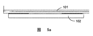
図5aおよび図5bは、支持ブロックの2種の好適な形状をそれぞれ示している。この支持ブロック102は、図5aに示すような平板状の支持ブロックを採用しても良く、または、図5bに示すようなV字形状の支持ブロックを採用しても良い。
Figures 5a and 5b show two preferred shapes of the support block, respectively. The
1つの実施例によれば、第1の支持体104−1は、第1のヒンジ103−1を介して第1の支持ブロック102−1に接続され、かつ、前記第2の支持体104−2は、第2のヒンジ103−2を介して第2の支持ブロック102−2に接続される。ヒンジ103と支持ブロック102との接続には、粘着テープを使用してもよく、またはネジによって固定するようにしてもよい。この第1の支持体104−1および第2の支持体104−2は、アセンブリ全体の支持体として機能することができ、アセンブリがより優れた耐風性を有するように風除け板として機能することもできる。支持体は、比較的大きい負荷応力を受けるため、一定の強度を有する必要がある。図1〜図4に示す実施例を参照して、そのうちの支持体104−1および104−2は、共に三角形状に形成されている。また、この三角形状の支持体は、コストを低減するために、プラスチックの収縮を考慮して、その中間部分をホロー状に形成することが好ましい。また、その形状としては、型材形状となっており、かつ押出成形によって製造され、これによって効率が高く、コストが低いなどのメリットを有する。
According to one embodiment, the first support 104-1 is connected to the first support block 102-1 via the first hinge 103-1, and the
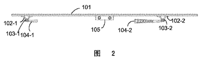
この第1の支持体104−1および第2の支持体104−2は、それぞれ第1のヒンジ103−1および第2のヒンジ103−2のまわりに回転することができる。例えば、図1に示す実施例では、折り畳み式アセンブリ100は、展開状態となっており、すなわち、支持体104−1および104−2は、パネル101に対して、例えばほぼ90度となるような垂直状態となっている。また、図2に示す実施例では、折り畳み式アセンブリ100は、折り畳み状態となっており、すなわち、支持体104−1および104−2は、パネル101に対して、例えばほぼ0度となるような水平状態となっている。そのため、折り畳み状態では、スペースおよびコストを節約することができるため、包装および搬送に非常に適する。また、実装時に、折り畳み式アセンブリを展開状態にして、この折り畳み式アセンブリ全体を適当な傾斜角度に調整させることができる。
The first support 104-1 and the second support 104-2 can rotate around the first hinge 103-1 and the second hinge 103-2, respectively. For example, in the embodiment shown in FIG. 1, the
また、太陽電池パネル101の傾斜角度を容易に調整するために、第1の支持体104−1および第2の支持体104−2は、共に長さが可変であるようになっている。例えば、第1の支持体104−1と第2の支持体104−2とは、長さが可変である伸縮式支持体を採用することができる。または、この第1の支持体104−1と第2の支持体104−2とは、高さを調整する効果を達成できるように、各段が共に90度折り曲げることができる多段構造を採用してもよい。または、本発明の別の実施例では、高度を変化させるために、パネル101または実装面(例えば地面または屋根など)に対する第1の支持体104−1および第2の支持体104−2の傾斜角度を選択および固定することができる構造を採用しても良い。勿論、本分野のほかの公知構造によって類似する傾斜角度の調整機能を実現することもできる。
Further, in order to easily adjust the inclination angle of the
また、図7には、支持体の別の好適な構造を示している。この支持体104は、例えば、クリップ形部材108および支持バー109によって構成される。クリップ形部材108の一端が支持ブロック102の底部に直接接続され、かつ、支持バー109の一端がこのクリップ形部材108の一方側の1つの結合点に接続され、この結合点と、支持バー109の他端と、クリップ形部材108の他端と、によって、1つの三角形状の支持構造が構成され、前後位置でパネルの支持強度を有効に得ることができる。また、この支持バー109は、支持体104全体の高度を調整するように、この結合点のまわりに回転することができる。
FIG. 7 shows another preferred structure of the support. The
例えば、図3は、本発明にかかる折り畳み式アセンブリの1つの実装例を示している。図4は、本発明にかかる折り畳み式アセンブリ全体の実装を示す図である。図中、第1の支持体104−1と第2の支持体104−2とは、共に実装面(例えば地面)に対して90度となる展開状態に折り畳み回転されている。また、ヒンジが回転することができるため、アセンブリの前後を貫通する固定ストリップ106が設けられる。例えば、図3に示す実施例では、2本の固定ストリップ106は、前記第1の支持体104−1および第2の支持体104−2にそれぞれ挿通され、これによって折り畳み式アセンブリ全体が固定される。図4に示すように、この固定ストリップ106は、前列のアセンブリにおける後側支持体および後列のアセンブリにおける前側支持体に挿通され、かつ、その中間位置において押圧ブロック107によって固定される。この固定ストリップ106は、ヒンジおよび前後の支持体の回転を大幅に制限することができ、同時に、各々のアセンブリ同士が接続されるため、折り畳み式アセンブリシステム全体はより安定するようになる。
For example, FIG. 3 illustrates one implementation of a folding assembly according to the present invention. FIG. 4 is a diagram showing the implementation of the entire folding assembly according to the present invention. In the figure, both the first support body 104-1 and the second support body 104-2 are folded and rotated in an unfolded state of 90 degrees with respect to the mounting surface (for example, the ground surface). Also, because the hinge can rotate, a fixed
図6には、押圧ブロックの1つの構造例を示している。図6に示すように、この押圧ブロック107は、押出成形によって形成された簡易なものであり、かつ四周に翼部が設けられる突出ブロック構造とすることができる。このような凸状の設計によって、前後の固定ストリップ106と容易に合わせることができ、かつその左右には、現地の風速によってバラストの重量を調整することができる。
FIG. 6 shows an example of the structure of the pressing block. As shown in FIG. 6, the
また、図3に示す実施例では、第1の支持体104−1は、第2の支持体104−2よりも長く設けられ、パネル101と実装面(例えば地面)との間に必要な傾斜角度を形成することができる。逆に、実装前、または実装後に折り畳み式アセンブリ全体を収納、包装および搬送する場合、第1の支持体104−1および第2の支持体104−2は、それぞれパネル101に平行となる折り畳み状態に折り畳み回転される(図2を参照)。この折り畳み状態では、折り畳み式アセンブリ100全体の体積が最小となり、包装および搬送の効率を向上することができる。
In the embodiment shown in FIG. 3, the first support 104-1 is provided longer than the second support 104-2, and the necessary inclination between the
一方、図1−図3に示すように、折り畳み式アセンブリ100は、パネル101の背面に設けられる接続箱105をさらに備える。
On the other hand, as shown in FIGS. 1 to 3, the
以下、本願の別の側面について、図8−図25を参照しながら説明する。また、以下の図8−図25に基づく説明は、単一の実施例に限定されるものではなく、実際の現場での状況またはデザインの需要に応じて任意に組み合わせ、修正、改良、調整を行うことによって、その他の代替的な実施形態を得ることができ、これは当業者にとっては明らかなことである。そして、図8−図25に基づいて説明する複数の技術方式は、以上で図1−図7に基づいて説明した複数の技術方式と組み合わせて使用することができ、これも本願およびその請求の範囲に含まれる精神および実質に属するものである。 Hereinafter, another aspect of the present application will be described with reference to FIGS. Further, the following description based on FIGS. 8 to 25 is not limited to a single embodiment, and can be arbitrarily combined, modified, improved, and adjusted according to actual site conditions or design demands. By doing so, other alternative embodiments can be obtained, which will be apparent to those skilled in the art. The plurality of technical schemes described based on FIGS. 8 to 25 can be used in combination with the plurality of technical schemes described above based on FIG. 1 to FIG. It belongs to the spirit and substance included in the scope.
図8は、本願の1つの側面におけるフレームレス太陽光発電アセンブリシステムを示す背面図である。図9は、本願の1つの側面における前後ホルダを図8に示す背面図における切断線1−1に沿って切断した断面図である。図10は、本願の1つの側面におけるフック部材を図8に示す背面図における切断線2−2に沿って切断した断面図である。 FIG. 8 is a rear view of the frameless photovoltaic assembly system according to one aspect of the present application. FIG. 9 is a cross-sectional view of the front and rear holders on one side surface of the present application taken along the cutting line 1-1 in the rear view shown in FIG. FIG. 10 is a cross-sectional view of the hook member on one side surface of the present application taken along the cutting line 2-2 in the rear view shown in FIG.
図8−図10に示すように、本願の1つの側面にかかるフレームレス太陽光発電アセンブリシステムは、フレームレス太陽光発電アセンブリ1と、粘着テープ2と、背面固定ブロック接続部材3と、固定ブロック4と、前方ブラケット5と、前方水平接続ビーム6と、後方ブラケット7と、後方風除け板8と、フック部材9と、背面フック接続部材9aと、スペーサー10と、ケーブルクランプ11と、底部接続部材(また、「キール」ともいう)12(図示せず)と、固定押圧ブロック13(図示せず)と、を備える。
As shown in FIGS. 8 to 10, the frameless photovoltaic power generation assembly system according to one aspect of the present application includes a frameless photovoltaic
1つの実施例によれば、太陽光発電アセンブリ1は、フレームレスアセンブリを採用している。図8に示すように、アセンブリ1の背面における接続箱(図中の左側に示される)におけるケーブルは、実装のために、そのうちの1本が長い一方、他の1本が短くなっている。ケーブルクリップ11は、アセンブリ1の裏側に固定されている。ケーブルクリップ11は、接着などによってアセンブリ1の背面に貼り付けられる。
According to one embodiment, the photovoltaic
図8および図9、図10に示す断面図から明らかなように、アセンブリ1は、前方ブラケット5(図8におけるアセンブリ1の上方に例示的に示される)および後方ブラケット7(図8におけるアセンブリ1の下方に例示的に示される)に接続されている。アセンブリ1の一方側において、前方ブラケット5に対応する接続位置に背面固定ブロック接続部材3および背面フック接続部材9aが接続されている。これらの2つの接続部材は、例えば接着などによってアセンブリ1に接続することができ、接着材としては、優れた耐候性および接着性を有し、すなわち、静荷重および動荷重が全体の安定性を確保できる要求を満足する必要があり、例えば粘着テープ2またはシリカゲルを使用することができる。同様に、アセンブリ1の他方側(すなわち、前方ブラケット5との接続側とは反対側)においても、後方ブラケット7に対応する接続位置に背面固定ブロック接続部材3および背面フック接続部材9aが接続されており、かつ、これらの2つの接続部材も、接着(すなわち、粘着テープ2)などによってアセンブリ1に接続されている。そして、アセンブリ1の背面であって後方ブラケット7と接触する位置には、搬送および実装時に後方ブラケット7がアセンブリ1の背面に衝突しないように、スペーサー10がさらに設けられる。
As is apparent from the cross-sectional views shown in FIGS. 8, 9, and 10, the
図11は、本願の1つの側面における背面固定ブロック接続部材3とアセンブリ1との接着を示す図である。図12は、本願の1つの側面における背面固定ブロック接続部材3をアセンブリ1に接着した後、固定ブロック4を接続した場合の接続構造を示す図である。図12は、本願の1つの側面における背面フック接続部材9aをアセンブリ1に接着した後、フック部材9を接続した場合の接続構造を示す図である。
FIG. 11 is a view showing adhesion between the back surface fixing
本願の1つの側面によれば、背面固定ブロック接続部材3および背面フック接続部材9aは、類似する構成を有し、かつ共に型材を使用して押出成形によって形成され、それらの断面は、図11および図13に示されている。背面固定ブロック接続部材3および背面フック接続部材9aの上部の両翼面、およびアセンブリ1における予定の接続部分には、共に粘着テープ2が設けられ、かつ、接続部材3および9aの、固定ブロック4およびフック部材9と接触する底面に、固定ブロックまたはフック部材の実装位置を制限するための浅溝が設けられる。同時に、接続部材3および9aのこの底面には、固定ブロックおよびフック部材における接続用皿穴と対応するねじ穴が設けられる。
According to one aspect of the present application, the back fixing
実装過程において、まずは、接続部材3および9aを(例えば、接着によって)アセンブリ1に接続させ、その後、固定ブロック4を皿ボルトによって背面固定ブロック接続部材3に接続し、フック部材9を皿ボルトによって背面フック接続部材9aに接続する。
In the mounting process, first, the connecting
本願の1つの実施例では、固定ブロック4は、L字形状となっている。固定ブロック4は、接続強度を確保するために、一定の厚みを有する必要がある。固定ブロック4の底面には、背面固定ブロック接続部材3および前後のブラケットに接続固定するために、皿ボルトを挿通させるための皿穴が設けられる。図12に示すように、固定ブロック4の皿穴が形成される側とは反対側に、前後ブラケットを順調に回転させるように、面取り部が形成されている。
In one embodiment of the present application, the fixed
本願の1つの実施例では、フック部材9の断面は、図13に示されている。フック部材9は、主として底面および円弧状フックによって構成されている。このような形状に形成する目的としては、主に、背面接続部材、前方水平接続ビーム6の上部におけるR字状部分(図10に示される)および後方風除け板8の上部におけるR字状部分(図9、図10に示される)とマッチングするためである。フック部材9の底面には、背面フック接続部材9aおよび前後ブラケットに接続固定するために、皿ボルトを挿通させるための皿穴が設けられている。フック部材9の円弧状フックは、前方水平接続ビーム6および後方風除け板8の上部におけるR字状部分とマッチングする凹状の円弧面を有しており、アセンブリ1が正の風圧(すなわち、アセンブリ1の正面に吹き付ける風圧であり、アセンブリ1を支持システムに圧入させる)を受けると、アセンブリ1が下方へ押圧されることによって、背面フック接続部材9aおよびフック部材9が下方へ押圧され、前方水平接続ビーム6の上部におけるR字状部分と後方風除け板8の上部におけるR字状部分と係合されることによって、アセンブリの荷重を下方の部材に徐々に伝達させる。同時に、フック部材9の下部における円弧状フックは、前後ブラケットが回転するときに回転ピンとして機能し、そして、アセンブリ1が負の風圧(すなわち、アセンブリ1の背面に吹き付ける風圧であり、アセンブリ1を支持システムから分離させる)を受けると、下部における円弧状フックは、前方水平接続ビーム6の上部におけるR字状部分と後方風除け板8の上部におけるR字状部分と係合することによって、支持システム全体とともに負の風圧に対抗する。
In one embodiment of the present application, a cross section of the
図14は、本願の1つの側面における前方ブラケットの組合せを示す断面図である。図中に示すように、前方ブラケットセットは、前方ブラケット5および前方水平接続ビーム6からなり、その上部がR字状に形成されている。前方ブラケットセットの上部は、皿ボルトによって固定ブロック4に接続され、下部が押圧プレートによって底部接続部材(キール)12(図示せず)に固定され、かつ底部接続部材(キール)12に対して垂直となっている。そのうち、前方ブラケット5の側面が前方水平接続ビーム6に密着し、前方ブラケット5が回転可能としているため、その先端部が円柱状に形成され、かつR字形状(断面から見る場合)に成型されるとともに、ねじ加工のために円孔が形成される。また、前方ブラケット5は、アセンブリ1の背面固定ブロック接続部材3と衝突しないように、その側部が傾斜面構造を採用している(図14の右側を参照)。前方ブラケット5の側部において、前方水平接続ビーム6に接続される部分(図中の左側に図示される)に凹溝が設けられ、この凹溝が前方水平接続ビーム6の側面における凹溝(図16に図示される)と係合され、かつこの凹溝にねじ穴が設けられ、接続ボルトをこのねじ穴と前方水平接続ビーム6の側面における凹溝に設けられるねじ穴とに貫通させて接続することによって、前方ブラケット5と前方水平接続ビーム6とが組み合わせられる。押圧プレートによる実装方式を採用しているため、前方ブラケットセットの下部には、実装溝が設けられる。
FIG. 14 is a cross-sectional view showing a combination of front brackets on one side of the present application. As shown in the drawing, the front bracket set includes a
前方ブラケット5については、その先端部に位置制限切欠きが形成される必要がある。図15は、本願の1つの側面における前方ブラケットにおける位置制限切欠きを示す図である。図中に示すように、前方ブラケットセットが実装位置に回転されると、この切欠きの底辺が固定ブロックの下辺に接触するようになる(位置制限については、図19の左側を参照する)。前方ブラケットの高さが低いため、この切欠きを大きく形成すると制限機能を発揮しないようになり、この場合、固定ブロックにおけるボルトを緩めることによって、システム内においてアセンブリ全体が回転可能になり、システムのメンテナンスにより便利になる。前方ブラケット5については、対称的に加工することによって形成される。前方ブラケット5の下部の、前方水平接続ビーム6に近い側は、底部よりも高い隅切込面に形成される。
The
図16は、本願の1つの側面における前方水平接続ビーム6を示す断面図である。この前方水平接続ビーム6は、アセンブリシステムの下側支持バーとするため、一定の強度および剛性を有する必要がある。前方水平接続ビーム6の上部は、円弧面に形成され、フック部材9と入れ子構造で係合することができ、前方ブラケットセットが順調に回転できるようになる。前方水平接続ビーム6の側面に凹溝が設けられ、この凹溝にねじ穴が形成され、接続ボルトを、このねじ穴に挿通して前方ブラケット5の側面における凹溝に形成されるねじ穴と接続することができ、また、接続ボルトは、この凹溝に収納することができ、前方水平接続ビーム6の側面から突出しないようになる。前方水平接続ビーム6は、その下部の辺が前方ブラケット5の隅切込面に係止されることによって、前方ブラケット5とよりよく一体化される。前方水平接続ビーム6の下部の主な機能としては、接続ビームの剛性を向上させるためのものである。前方水平接続ビーム6の下部の他端部は、前方ブラケット5の下部に密着し、切欠きが形成され、かつボルト穴が打ち抜かれている。
FIG. 16 is a cross-sectional view showing the front horizontal connection beam 6 on one side of the present application. The front horizontal connecting beam 6 needs to have a certain strength and rigidity in order to be a lower support bar of the assembly system. The upper part of the front horizontal connection beam 6 is formed in an arcuate surface and can be engaged with the
図17は、本願の1つの側面における後方ブラケットセットを示す断面図である。後方ブラケットセットは、後方ブラケット7および後方風除け板8とからなり、その上部がR字状に形成されている。図14に示す前方ブラケットセットと同様に、後方ブラケットセットの上部は、皿ボルトによって固定ブロック4に接続され、下部が押圧プレートによって底部接続部材(キール)12に固定されている。そのうち、後方ブラケット7の側面が後方風除け板8に密着し、後方ブラケット7が同様に回転可能としているため、その先端部が円柱状に形成され、かつR字状(断面から見る場合)に成型されるとともに、ねじ加工のために円孔が形成される。後方ブラケット7は、アセンブリ1の背面固定ブロック接続部材3と衝突しないように、その側部が傾斜面構造を採用している(図17の右側を参照)。後方ブラケット7の側部において、後方風除け板に接続される部分(図中の左側に図示的に示される)に凹溝が設けられ、この凹溝が後方風除け板8の側面における凹溝(図18に図示される)と係合され、かつこの凹溝にねじ穴が設けられ、接続ボルトをこのねじ穴と後方風除け板8の側面における凹溝に設けられるねじ穴とに貫通させて接続することによって、後方ブラケット7と後方風除け板8とが組み合わせられる。押圧プレートによる実装方式を採用しているため、後方ブラケットセットの下部には、実装溝が設けられる。
FIG. 17 is a cross-sectional view showing a rear bracket set on one side surface of the present application. The rear bracket set includes a
後方ブラケット7については、その先端部に同様に位置制限切欠きが形成される必要がある。図15は、本願の1つの側面における後方ブラケットの位置制限切欠きを示す図である。図中に示すように、後方ブラケット7が実装位置に回転されると、この切欠きの底辺が固定ブロックの下辺に接触するようになる(位置制限については、図19の右側を参照する)。後方ブラケット7については、対称的に加工することによって形成される。後方ブラケット7の下部の、後方風除け板8に近い側は、底部よりも高い隅切込面が形成されている。
As for the
図18は、本願の1つの側面における後方風除け板8を示す断面図である。後方風除け板8は、主として後部から風除けを行い、アセンブリ1の背面に風荷重が与えられないようにすると同時に、アセンブリの上側支持バーとして、その上部が円弧面に形成され、フック部材9と入れ子構造で係合することができ、後方ブラケットセットが順調に回転できるようになる。後方風除け板8の側面に凹溝が設けられ、この凹溝にねじ穴が形成され、接続ボルトを、このねじ穴に挿通して後方ブラケット7の側面における凹溝に形成されるねじ穴と接続することができ、また、接続ボルトは、この凹溝に収納することができ、後方風除け板8の側面から突出しないようになる。後方風除け板8の下部は、係合構造を採用しており、後方ブラケット7の下部の隅切込面に係合され、後方ブラケット7とより良く一体化される。システム全体として優れた通風性を有するために、後方風除け板8には、逆方向の開口が形成されている。
FIG. 18 is a cross-sectional view showing the rear windbreak plate 8 on one side surface of the present application. The rear windbreak plate 8 mainly windbreaks from the rear part so that no wind load is applied to the back surface of the
本願の1つの側面によれば、太陽光発電アセンブリシステム全体において、後方ブラケット7が前方ブラケット5よりも高くなるため、後方ブラケット7がアセンブリ1に対して直角を成しており、後方ブラケットの受力を改善することができる。
According to one aspect of the present application, since the
アセンブリシステムが現場に搬送されると、固定ブロック4における皿ボルトを緩めることによって、前方ブラケットセットおよび後方ブラケットセットは、滑らかに回転可能となり、実装位置に回転された後、図19に示すように、皿ボルトを再度締め付けて実装待ちの状態となる。図20は、前後ブラケットが展開された後の、フックと後方風除け板および前方水平接続ビームとの結合状況を示している。なお、図19、図20には、共にアセンブリ1全体ではなく、アセンブリ1と前後ブラケットとの接続部分のみを示しており、アセンブリ1の中間部分が図面から省略されている。
When the assembly system is transported to the site, the front bracket set and the rear bracket set can be smoothly rotated by loosening the countersunk bolts in the fixing
図21は、本願の1つの側面における底部接続部材(キール)を示す断面図である。そのうち、底部接続部材(キール)12の上部の左右両側には、それぞれ押圧プレート用ボルト溝12−1が設けられ、かつ、上部の表面のうち前側/後方ブラケットセットとの接続部位に逆リップルが設けられている。底部接続部材(キール)12の上表面の中間には、アセンブリとの間に一定の隙間が存在するように、突出部分が設けられている。本願の1つの好適な実施例によれば、中間における突出部分の幅度を、28mmとすることができる。同時に、底部接続部材(キール)の中央キャビティーは、比較的大きくなっている。中間部分のキールの接続長さが短いため、アセンブリ1の前後列におけるケーブルが通過することができる。
FIG. 21 is a cross-sectional view showing a bottom connecting member (a keel) on one side surface of the present application. Among them, on both the left and right sides of the upper part of the bottom connection member (keel) 12, there are respectively provided pressure plate bolt grooves 12-1, and reverse ripples are present at the connection part of the upper surface with the front / rear bracket set. Is provided. A projecting portion is provided in the middle of the upper surface of the bottom connecting member (keel) 12 so that a certain gap exists between the bottom connecting member (keel) 12 and the assembly. According to one preferred embodiment of the present application, the width of the protruding portion in the middle can be 28 mm. At the same time, the central cavity of the bottom connection member (keel) is relatively large. Since the connection length of the keel in the middle part is short, the cables in the front and rear rows of the
図25は、本願の1つの側面におけるシステムの現場実装を示すフローチャートである。システムを現場で実装するときに、先ずは、ステップ2501のように、底部接続部材(キール)12を敷設する。次に、ステップ2503に移行し、図19−図20に示すように、アセンブリ1の前方ブラケットセットおよび後方ブラケットセットを展開させ(すなわち、締め付けボルトを緩める)、かつ前側/後方ブラケットセットを実装位置に回転させて再度締め付ける。その後、ステップ2505において、実装位置に回転されたアセンブリ1を底部接続部材(キール)12の上に載置させる。ステップ2507において、全ての部材の検査が完了した後、固定用押圧ブロック13を配置して、前方ブラケットセットと後方ブラケットセットとを固定する。図22に示すように、固定用押圧ブロック13の一部が、前方ブラケットセットおよび後方ブラケットセットの下部に設けられる実装溝に係合される。その後、ステップ2509において、押圧プレート用ボルト14を固定用押圧ブロック13に挿入させ、この押圧プレート用ボルト14の一部は、底部接続部材(キール)12の押圧プレート用ボルト溝12−1に収納され、かつ、このボルトを締め付けることによって、アセンブリシステムを底部接続部材(キール)12に固定させる。このような実装方式は、簡単であり、現場で実装作業を容易に行うことができる。具体的な実装構造は、図22、図23に示される。1つの好適な実施例では、迅速かつ容易に実装できるように、実装前に複数の木製フィラーストリップを準備し、かつ押圧プレート用ボルト14を底部接続部材(キール)12の押圧プレート用ボルト溝12−1に事前に放置する。同時に、前記押圧プレート用ボルトと前記固定用押圧ブロックとを締め付ける前に、全てのケーブルを接続し、かつ、接続完了後に残ったケーブルを底部接続部材(キール)12の内側に収納させる必要がある。
FIG. 25 is a flowchart illustrating on-site implementation of the system in one aspect of the present application. When mounting the system in the field, first, as shown in
図24は、本願の1つの側面における太陽光発電アセンブリのアレイシステム全体の縦断面を示す図である。なお、図24には、アセンブリ1の全体ではなく、アセンブリ1、前後ブラケットおよび底部接続部材(キール)の間の接続部分のみを示しており、アセンブリ1の中間部分が図面から省略されている。図24に示すアレイシステム全体では、複数のアセンブリ1が1列に配列されている。図24には、最前列のアセンブリシステムA、最後列のアセンブリシステムD、前から2列目のアセンブリシステムBおよび後ろから2列目のアセンブリシステムCのみを示している。図面から分かるように、アセンブリシステムBとアセンブリシステムCとの間には、実際の需要に応じて複数のアセンブリシステムを実装することができる。図示したように、最前列および最後列の底部接続部材(キール)a、dは、それぞれ最前列のアセンブリシステムAおよび最後列のアセンブリシステムDにおける前後ホルダセットを接続する。前から2列目のアセンブリシステムBでは、その前方ブラケットセットが最前列の底部接続部材(キール)aに接続されるとともに、後方ブラケットセットが前から2列目の底部接続部材(キール)bに接続される。これによって類推すると、後ろから2列目のアセンブリシステムCでは、その前方ブラケットセットが後ろから2列目の底部接続部材(キール)c(図示せず)に接続されるとともに、後方ブラケットセットが前から最後列の底部接続部材(キール)dに接続される。これから分かるように、4つのアセンブリシステムA、B、C、Dのみを有する場合、3つの底部接続部材(キール)a、b、dのみを必要とし、後ろから2列目のアセンブリシステムCの前方ブラケットセットが、前から2列目の底部接続部材(キール)bに直接接続されている。4つ以上のn個のアセンブリシステムがある場合、中間に位置するキール(すなわち、前から2列目からn−1列目までのキール)は、それぞれ隣り合う2つのアセンブリシステムのうち、一方のアセンブリの後方ブラケットセットと他方のアセンブリシステムの前方ブラケットセットとに接続されるようになる。これによって、太陽光発電アセンブリのアレイシステムが構成される。
FIG. 24 is a view showing a longitudinal section of the entire array system of the photovoltaic power generation assembly according to one aspect of the present application. FIG. 24 shows not only the
本願の上記の各々の実施例に提供される太陽光発電アセンブリおよびその実装構造によれば、以下のようなメリットを有する。
1. パネルと支持構造とが一体構造に構成され、かつ、支持体の折り畳み回転によって収納および実装傾斜度の調整を実現することができる。
2. この屋根アセンブリは、フレームレスアセンブリであり、アセンブリの背面に背面固定ブロック接続部材が接着され、背面固定ブロック接続部材に前後ブラケットを接続するための固定ブロックが実装され、背面固定ブロック接続部材には、固定ブロックを位置決めするための凹溝が形成されるようにして、製造コストを低減させることができる。
3. この屋根アセンブリでは、前後ブラケットは、それぞれ固定ブロックによって接続され、かつ、前後ブラケットが回転可能になるため、搬送に便利になり、また、現場で実装する時に、前後ブラケットを開放させて所定の位置に回転させればよい。また、前方ブラケットセットは、前方ブラケットと前方水平接続ビームとからなり、後方ブラケットセットは、後方ブラケットと後方風除け板とからなる。
4. この屋根アセンブリでは、背面に背面フック接続部材が接着され、この背面フック接続部材に、フックが接続されており、このフックは、負の風圧が与えられるときに、アセンブリと前後ブラケットとを接続させる機能を発揮する。また、このフックは、正の風圧が与えられるときに荷重を伝達する機能を発揮する。
5. 前後ブラケットは、アルミニウム型材で押出成形によって形成されるため、部品の加工が簡単になり、重量が軽くなる。また、工場でアセンブリ全体を組み立てて、現場では、屋根に底部接続部材(キール)を敷設して、押圧プレートによって固定させればよいため、現場での工事が簡単になる。
6. 前方ブラケットセットにおける前方水平接続ビームと後方ブラケットセットにおける後方風除け板とは、構造において支持作用をそれぞれ発揮すると同時に、中間のフックによって荷重を分散させ、アセンブリの支持点を増加することによって、アセンブリの機械強度を向上させることができる。
7. 同一の列における2つのアセンブリの間の隙間が30mmであり、または、風除け板に逆方向の開口を通風口として形成することによって、アセンブリの通風性を保証することができる。
8. このアセンブリは、前後のアセンブリが工場で事前に接続されるため、現場での実装工事を減少させ、実装時間を減少させ、効率を向上させるとともに実装コストを低減させることができる。
9. 支持構造を収納するときに、支持体をパネルに平行になるように折り畳み回転させるだけで、折り畳み式アセンブリ全体の空間を最小にし、かつ、実装システムの構成要素を減少させることができ、また、アセンブリの搬送に便利になり、搬送費用を減少させることができる。
10. アセンブリの重量が軽くなるため、屋根に与える荷重を減少させることができ、かつ、アセンブリを構成する部品は、特殊な加工方式を使用せず、製造コストを減少させることができる。
The photovoltaic power generation assembly and its mounting structure provided in each of the above embodiments of the present application have the following merits.
1. The panel and the support structure are configured as an integral structure, and the accommodation and mounting inclination can be adjusted by folding the support.
2. This roof assembly is a frameless assembly, and a rear fixing block connecting member is bonded to the back of the assembly, and a fixing block for connecting front and rear brackets is mounted on the rear fixing block connecting member. The manufacturing cost can be reduced by forming a concave groove for positioning the fixed block.
3. In this roof assembly, the front and rear brackets are connected by fixed blocks, respectively, and the front and rear brackets can be rotated, which is convenient for transportation. Also, when mounting on the site, the front and rear brackets are opened to a predetermined position. Rotate to The front bracket set includes a front bracket and a front horizontal connection beam, and the rear bracket set includes a rear bracket and a rear wind shield.
4). In this roof assembly, a back hook connecting member is bonded to the back surface, and the hook is connected to the back hook connecting member, and this hook connects the assembly and the front and rear brackets when a negative wind pressure is applied. Demonstrate the function. Further, the hook exhibits a function of transmitting a load when a positive wind pressure is applied.
5. Since the front and rear brackets are formed by extrusion molding with an aluminum mold, the processing of the parts is simplified and the weight is reduced. In addition, since the entire assembly is assembled at the factory, and a bottom connection member (keel) is laid on the roof and fixed by a pressing plate, the construction at the site is simplified.
6). The front horizontal connection beam in the front bracket set and the rear windbreak plate in the rear bracket set each provide support in the structure, while at the same time distributing the load by an intermediate hook and increasing the support point of the assembly. Mechanical strength can be improved.
7). The clearance between the two assemblies in the same row is 30 mm, or the ventilation of the assembly can be ensured by forming a reverse opening as a vent in the windshield.
8). In this assembly, since the front and rear assemblies are connected in advance in the factory, it is possible to reduce on-site mounting work, reduce mounting time, improve efficiency, and reduce mounting cost.
9. When the support structure is stored, it is possible to minimize the space of the entire folding assembly and reduce the components of the mounting system by simply folding and rotating the support so that it is parallel to the panel. It becomes convenient to transport the assembly, and the transportation cost can be reduced.
10. Since the weight of the assembly is reduced, the load applied to the roof can be reduced, and the parts constituting the assembly do not use a special processing method, and the manufacturing cost can be reduced.
本発明の精神および範囲を超えなければ、本発明の以上例示した実施例に対して、各種の修正および変形を行うことが可能であり、これは当業者にとっては明らかなことである。よって、本発明の請求の範囲およびその等価の技術方案の範囲内において本発明に対して行う修正および変形も、本発明の保護範囲に含まれる。 Various modifications and variations can be made to the above-exemplified embodiments of the present invention without departing from the spirit and scope of the present invention, as will be apparent to those skilled in the art. Therefore, modifications and changes made to the present invention within the scope of the claims of the present invention and the equivalent technical solutions are also included in the protection scope of the present invention.
1 太陽光発電アセンブリ、2 粘着テープ、3 第1の背面固定ブロック接続部材,第2の背面固定ブロック接続部材、4 固定ブロック、5 前方ブラケット、6 前方水平接続ビーム、7 後方ブラケット、8 後方風除け板、9 フック部材、9a 第1の背面フック接続部材,第2の背面フック接続部材、12 底部接続部材、12−1 押圧プレート用ボルト溝、13 固定用押圧ブロック、14 押圧プレート用ボルト、101 パネル、102−1 第1の支持ブロック、102−2 第2の支持ブロック、103−1 第1のヒンジ、103−2 第2のヒンジ、104−1 第1の支持体、104−2 第2の支持体、105 接続箱、108 クリップ形部材、109 支持バー
DESCRIPTION OF
Claims (13)
前記太陽光発電アセンブリの第2側に接続されるとともに、後方ブラケットセットに接続される第2の背面固定ブロック接続部材(3)および第2の背面フック接続部材(9a)と、が接続される複数の太陽光発電アセンブリ(1)を備え、
前記前方ブラケットセットは、前記第1の背面固定ブロック接続部材(3)および第1の背面フック接続部材(9a)のまわりに回転自在となっており、
前記後方ブラケットセットは、前記第2の背面固定ブロック接続部材(3)および第2の背面フック接続部材(9a)のまわりに回転自在となっており、
前記複数の太陽光発電アセンブリ(1)は、1列に配列され、かつそれぞれが底部接続部材(12)によって接続されることによって、太陽光発電アセンブリの全体アレイシステムが構成され、
1列目の太陽光発電アセンブリの前方ブラケットセットおよび後方ブラケットセットは、共に1列目の底部接続部材に接続され、
最後列の太陽光発電アセンブリの前方ブラケットセットおよび後方ブラケットセットは、共に最後列の底部接続部材に接続され、
1列目の太陽光発電アセンブリと最後列の太陽光発電アセンブリとの間に位置する太陽光発電アセンブリのそれぞれは、その前方ブラケットセットが1つ前の列における底部接続部材に接続されると共に、後方ブラケットセットが1つ後ろの列における底部接続部材に接続され、
前記第1の背面固定ブロック接続部材および第1の背面フック接続部材、第2の背面固定ブロック接続部材および第2の背面フック接続部材は、共に粘着テープ(2)によって前記太陽光発電アセンブリに接続され、
前記粘着テープは、前記第1および第2の背面固定ブロック接続部材ならびに第1および第2の背面フック接続部材の上部の両翼面と太陽光発電アセンブリにおける予定の接続部分とに設けられており、
前記第1および第2の背面固定ブロック接続部材ならびに第1および第2の背面フック接続部材は、構造が類似しており、共に型材を使用して押出成形によって形成され、
前記第1および第2の背面固定ブロック接続部材は、固定ブロック(4)によって前記前方ブラケットセットおよび前記後方ブラケットセットにそれぞれ接続され、
前記第1および第2の背面フック接続部材は、フック部材(9)によって前記前方ブラケットセットおよび前記後方ブラケットセットにそれぞれ接続され、
前記第1および第2の背面固定ブロック接続部材と第1および第2の背面フック接続部材とは、前記固定ブロックまたは前記フック部材と接触する底面に、前記固定ブロックまたはフック部材の実装位置を制限するための浅溝が設けられており、
前記底面には、前記固定ブロックまたはフック部材における皿穴と対応するネジ穴がさらに設けられていることを特徴とする太陽光発電アセンブリの実装構造。 A first back fixed block connecting member (3) and a first back hook connecting member (9a) connected to the first side of the photovoltaic assembly and connected to the front bracket set;
The second back fixed block connecting member (3) and the second back hook connecting member (9a) connected to the second side of the photovoltaic power generation assembly and connected to the rear bracket set are connected. Comprising a plurality of photovoltaic assemblies (1),
The front bracket set is rotatable around the first back fixed block connecting member (3) and the first back hook connecting member (9a),
The rear bracket set is rotatable around the second back fixed block connecting member (3) and the second back hook connecting member (9a),
The plurality of photovoltaic power generation assemblies (1) are arranged in a row, and each is connected by a bottom connection member (12), thereby constituting an entire array system of the photovoltaic power generation assemblies,
The front bracket set and the rear bracket set of the photovoltaic assembly in the first row are both connected to the bottom connection member in the first row,
The front bracket set and rear bracket set of the last row photovoltaic assembly are both connected to the bottom connection member of the last row,
Each of the photovoltaic assemblies located between the first row photovoltaic assembly and the last row photovoltaic assembly has its front bracket set connected to the bottom connection member in the previous row, The rear bracket set is connected to the bottom connection member in the next row ,
The first back surface fixing block connecting member, the first back surface hook connecting member, the second back surface fixing block connecting member, and the second back surface hook connecting member are both connected to the photovoltaic assembly by an adhesive tape (2). And
The adhesive tape is provided on the first and second back surface fixing block connecting members and both wing surfaces on the top of the first and second back hook connecting members and a predetermined connecting portion in the photovoltaic power generation assembly,
The first and second back fixing block connecting members and the first and second back hook connecting members are similar in structure, and both are formed by extrusion using a mold,
The first and second rear fixed block connecting members are connected to the front bracket set and the rear bracket set by a fixed block (4), respectively.
The first and second back hook connecting members are connected to the front bracket set and the rear bracket set by hook members (9), respectively.
The first and second back surface fixing block connecting members and the first and second back surface hook connecting members restrict the mounting position of the fixing block or the hook member on the bottom surface contacting the fixing block or the hook member. There is a shallow groove to
Mounting structure wherein the bottom surface, photovoltaic assembly characterized that you have screw holes corresponding to the countersink is further provided in the fixed block or the hook member.
前記固定ブロックの底面には、前記第1および第2の背面固定ブロック接続部材と接続するために、皿ボルトを挿通させるための皿穴が設けられており、
前記固定ブロックは、皿穴が形成される側とは反対側に面取り部が設けられていることを特徴とする請求項1に記載の太陽光発電アセンブリの実装構造。 The fixed block is L-shaped and has a certain thickness to ensure connection strength,
The bottom surface of the fixed block is provided with a countersink for inserting a countersunk bolt to connect with the first and second back surface fixed block connecting members,
The mounting structure for a photovoltaic power generation assembly according to claim 1 , wherein the fixing block is provided with a chamfered portion on a side opposite to a side where the countersink is formed.
前記フック部材の底面には、前記第1および第2の背面フック接続部材と接続するために、皿ボルトを挿通させるための皿穴が設けられており、
前記円弧状フックには、前記前方ブラケットセットおよび前記後方ブラケットセットの上部におけるR字状部分とマッチングする凹状の円形面が設けられ、
太陽光発電アセンブリに正の風圧が与えられて下方へ押圧される場合、前記凹状の円形面が前記上部におけるR字状部分に合わせられ、アセンブリの荷重を下方の部材に徐々に伝達させる一方、前記太陽光発電アセンブリに負の風圧が与えられて前記太陽光発電アセンブリの接続構造から吹き離される場合、前記円弧状フックが前記前方ブラケットセットおよび前記後方ブラケットセットの上部のR字状部分に係止され、太陽光発電アセンブリの接続構造とともに負の風圧に対抗し、
前記円弧状フックは、前記前方ブラケットセットおよび前記後方ブラケットセットが回転する時に回転ピンとして機能することを特徴とする請求項2に記載の太陽光発電アセンブリの実装構造。 The hook member is composed of a bottom surface and an arc-shaped hook,
The bottom surface of the hook member is provided with a countersink for inserting a countersunk bolt to connect with the first and second back hook connecting members,
The arcuate hook is provided with a concave circular surface that matches an R-shaped portion at the top of the front bracket set and the rear bracket set,
When a positive wind pressure is applied to the photovoltaic power generation assembly and pressed downward, the concave circular surface is aligned with the R-shaped portion in the upper part, while gradually transferring the load of the assembly to the lower member, When the negative wind pressure is applied to the photovoltaic power generation assembly and blown away from the connection structure of the photovoltaic power generation assembly, the arc-shaped hooks are engaged with the R-shaped portions of the upper portions of the front bracket set and the rear bracket set. Against the negative wind pressure along with the connection structure of the photovoltaic assembly,
The mounting structure for a solar power generation assembly according to claim 2 , wherein the arc-shaped hook functions as a rotation pin when the front bracket set and the rear bracket set rotate.
前記前方ブラケットセットの下部は、押圧プレートによって底部接続部材(12)に固定され、かつ前記底部接続部材に対して垂直となっており、そのうち、前記前方ブラケットセットの側部は、前記第1の背面固定ブロック接続部材と衝突しないように、傾斜面構造を採用しており、
前記前方ブラケットの側面が前記前方水平接続ビームに密着し、かつ前記前方ブラケットと前記前方水平接続ビームとは、互いに接続される側面に凹溝がそれぞれ設けられ、
前記凹溝は、相互にマッチングするとともにネジ穴がそれぞれ設けられ、接続ボルトを前記ネジ穴に挿通させることによって前記前方ブラケットと前記前方水平接続ビームとを組み合わせ、
前記前方ブラケットセットの下部には、固定用押圧プレートと合わせるように実装溝が設けられ、かつ前記前方ブラケットの上部には、位置制限切欠きが形成され、前記前方ブラケットセットが実装位置に回転されたときに、前記位置制限切欠きの底辺が前記固定ブロックの下辺に接触して位置制限の機能を発揮することを特徴とする請求項3に記載の太陽光発電アセンブリの実装構造。 The front bracket set includes a front bracket (5) and a front horizontal connection beam (6). An R-shaped portion is formed on the upper bracket set, and the front bracket set is connected to the fixed block by a countersunk bolt. Is fitted to the hook member by a shaped part,
The lower part of the front bracket set is fixed to the bottom connection member (12) by a pressing plate and is perpendicular to the bottom connection member, of which the side part of the front bracket set is the first An inclined surface structure is adopted so as not to collide with the back fixed block connection member.
The side surface of the front bracket is in close contact with the front horizontal connection beam, and the front bracket and the front horizontal connection beam are each provided with a concave groove on a side surface connected to each other,
The concave grooves are matched with each other and provided with screw holes, respectively, and the front bracket and the front horizontal connection beam are combined by inserting a connection bolt into the screw hole,
A mounting groove is provided in the lower part of the front bracket set so as to be aligned with the fixing pressing plate, and a position restriction notch is formed in the upper part of the front bracket, and the front bracket set is rotated to the mounting position. 4. The mounting structure for a photovoltaic power generation assembly according to claim 3 , wherein a bottom side of the position restriction notch contacts a lower side of the fixed block to exert a function of position restriction.
接続ボルトは、前記前方水平接続ビームの側面における凹溝に収納することができ、前記前方水平接続ビームの側面から突出しないようになり、
前記前方ブラケットの下部には、前記前方水平接続ビームに近い側に底部より高い隅切込面が形成され、前記前方水平接続ビームは、その下部の一方端が前記隅切込面に係止することによって、前記前方ブラケットとより良く一体化され、
前記前方水平接続ビームの下部の他方端は、前記前方ブラケットの下部に密着し、かつ1つの切欠きが形成されるとともに、ボルト穴が打ち抜かれていることを特徴とする請求項4に記載の太陽光発電アセンブリの実装構造。 The upper part of the front horizontal connection beam is formed in an arc surface so that the front bracket set can smoothly rotate by fitting with the hook member and the nesting structure,
The connection bolt can be housed in a concave groove on the side surface of the front horizontal connection beam, and does not protrude from the side surface of the front horizontal connection beam.
A lower corner of the front bracket is formed with a corner cut surface higher than the bottom on the side close to the front horizontal connection beam, and one end of the lower portion of the front horizontal connection beam is locked to the corner cut surface. Better integrated with the front bracket,
Bottom of the other end of the front horizontal connection beam according to claim 4 in close contact with the lower portion of the front bracket, and one with the notches formed, characterized in that the bolt holes are punched Mounting structure of solar power assembly.
前記後方ブラケットは、同様に回転可能としており、その先端部が円柱形に形成されるとともにR字状に成形され、かつ、ネジ加工のために円孔が形成されており、前記後方ブラケットの側部は、前記第2の背面固定ブロック接続部材(3)と衝突しないように、傾斜面構造を採用しており、
前記後方ブラケットの側面が前記後方風除け板に密着し、かつ互いに接続される側面に凹溝がそれぞれ設けられ、
前記凹溝は、互いにマッチングするとともにネジ穴が形成され、接続ボルトを前記ネジ穴に挿通させることによって前記後方ブラケットと前記後方風除け板とを組み合わせ、
前記後方ブラケットセットの下部には、実装溝が設けられるとともに、前記後方ブラケットの上部には位置制限切欠きが形成され、前記後方ブラケットセットが実装位置に回転されたときに、前記位置制限切欠きの底辺が前記固定ブロックの下辺に接触して位置制限の機能を発揮することを特徴とする請求項5に記載の太陽光発電アセンブリの実装構造。 The rear bracket set includes a rear bracket (7) and a rear windbreak plate (8), and an R-shaped portion is formed on an upper portion thereof. The upper portion of the rear bracket set is fixed by a countersunk bolt (4). And the lower part is fixed to the bottom connection member (12) by the pressing plate,
Similarly, the rear bracket is rotatable, its tip is formed in a cylindrical shape and is formed in an R shape, and a circular hole is formed for screw processing, and the rear bracket side The portion adopts an inclined surface structure so as not to collide with the second back fixed block connecting member (3),
The side surfaces of the rear bracket are in close contact with the rear windbreak plate, and concave grooves are provided on the side surfaces connected to each other,
The concave groove is matched with each other and a screw hole is formed, and the rear bracket and the rear windbreak plate are combined by inserting a connection bolt into the screw hole,
A mounting groove is provided in the lower part of the rear bracket set, and a position restriction notch is formed in the upper part of the rear bracket. When the rear bracket set is rotated to the mounting position, the position restriction notch 6. The mounting structure for a photovoltaic power generation assembly according to claim 5 , wherein a bottom side of the solar cell contacts a lower side of the fixed block to exert a function of position restriction.
前記後方風除け板の上部は、前記フック部材と入れ子構造で合わせるように円弧面に形成され、前記後方ブラケットセットが滑らかに回転することができるようになり、
前記接続ボルトは、前記後方風除け板の側面における前記凹溝に収納することができ、前記後方風除け板の側面から突出しないようになり、
前記後方ブラケットの下部には、前記後方風除け板に近い側に底部より高い隅切込面が形成され、前記後方風除け板の下部は、係合構造を採用しており、前記後方ブラケットの前記隅切込面に係止することによって、前記後方ブラケットとより良く一体化され、
前記後方風除け板には、太陽光発電アセンブリ全体の実装構造が優れた通風性を有するように逆方向の開口が形成されることを特徴とする請求項6に記載の太陽光発電アセンブリの実装構造。 One function of the rear windshield is to perform windbreak from the rear so that no wind load is applied to the back of the photovoltaic assembly,
The upper part of the rear windbreak plate is formed in an arc surface so as to be fitted with the hook member in a nesting structure, and the rear bracket set can smoothly rotate,
The connection bolt can be housed in the groove on the side surface of the rear windbreak plate, and does not protrude from the side surface of the rear windscreen plate,
In the lower part of the rear bracket, a corner cut surface higher than the bottom is formed on the side close to the rear wind shield, and the lower part of the rear wind shield uses an engagement structure, and the corner of the rear bracket is By locking to the cut surface, it is better integrated with the rear bracket,
The mounting structure for a solar power generation assembly according to claim 6 , wherein the rear windbreak plate has an opening in a reverse direction so that the mounting structure of the entire solar power generation assembly has excellent ventilation. .
前記底部接続部材の上部の表面の中間には、アセンブリの間に一定の隙間が存在するように突出部分が形成されることを特徴とする請求項7に記載の太陽光発電アセンブリの実装構造。 On both the left and right sides of the upper part of the bottom connection member (12), there are respectively provided pressure plate bolt grooves (12-1), and at the connection site between the front bracket set and the rear bracket set on the upper surface. Reverse ripple is formed,
The mounting structure for a photovoltaic power generation assembly according to claim 7 , wherein a protruding portion is formed in the middle of the upper surface of the bottom connection member so that a certain gap exists between the assemblies.
底部接続部材(12)を敷設するステップと、
アセンブリ(1)の前方ブラケットセットおよび後方ブラケットセットを展開させ、実装位置に回転させた後再度締め付けさせるステップと、
実装位置に回転された太陽光発電アセンブリを前記底部接続部材の上に載置させるステップと、
全ての部材の検査が完了した後、前記前方ブラケットセットと前記後方ブラケットセットとを固定するために、固定用押圧ブロック(13)を覆うステップと、
押圧プレート用ボルト(14)を前記固定用押圧ブロック(13)に挿入させて締め付けることによって、前記太陽光発電アセンブリを前記底部接続部材に固定させるステップと、を含むことを特徴とする太陽光発電アセンブリの実装方法。 A method for mounting the mounting structure of the photovoltaic power generation assembly according to any one of claims 1 to 10 ,
Laying the bottom connecting member (12);
Unfolding the front bracket set and the rear bracket set of the assembly (1), rotating them to the mounting position and then tightening them again;
Placing the photovoltaic assembly rotated to a mounting position on the bottom connecting member;
After the inspection of all members is completed, covering the fixing pressing block (13) to fix the front bracket set and the rear bracket set;
Fixing the photovoltaic power generation assembly to the bottom connecting member by inserting and tightening a pressing plate bolt (14) into the fixing pressing block (13). Assembly assembly method.
Applications Claiming Priority (5)
| Application Number | Priority Date | Filing Date | Title |
|---|---|---|---|
| CN201210134804.1A CN102683444B (en) | 2012-05-03 | 2012-05-03 | Folding type member |
| CN201210134804.1 | 2012-05-03 | ||
| CN201210369274.9A CN102881743B (en) | 2012-09-28 | 2012-09-28 | A kind of photovoltaic component mounting structure and installation method thereof |
| CN201210369274.9 | 2012-09-28 | ||
| PCT/CN2012/083316 WO2013163866A1 (en) | 2012-05-03 | 2012-10-22 | Folded photovoltaic assembly mounting structure and mounting method therefor |
Publications (2)
| Publication Number | Publication Date |
|---|---|
| JP2015521457A JP2015521457A (en) | 2015-07-27 |
| JP6157594B2 true JP6157594B2 (en) | 2017-07-05 |
Family
ID=49514197
Family Applications (1)
| Application Number | Title | Priority Date | Filing Date |
|---|---|---|---|
| JP2015509283A Active JP6157594B2 (en) | 2012-05-03 | 2012-10-22 | Mounting structure of folding photovoltaic power generation assembly and mounting method thereof |
Country Status (6)
| Country | Link |
|---|---|
| US (1) | US9559633B2 (en) |
| EP (1) | EP2884545B1 (en) |
| JP (1) | JP6157594B2 (en) |
| ES (1) | ES2950476T3 (en) |
| IN (1) | IN2014DN10302A (en) |
| WO (1) | WO2013163866A1 (en) |
Families Citing this family (11)
| Publication number | Priority date | Publication date | Assignee | Title |
|---|---|---|---|---|
| JP6573485B2 (en) * | 2015-06-01 | 2019-09-11 | 旭化成ホームズ株式会社 | Fixed member |
| CN107453699B (en) * | 2017-08-28 | 2024-01-23 | 江西清华泰豪三波电机有限公司 | Photovoltaic module and photovoltaic device |
| CN108155860A (en) * | 2017-12-30 | 2018-06-12 | 安徽伙伴电气有限公司 | A kind of adjustable servo-actuated chassis for solar photovoltaic assembly |
| CN108540054B (en) * | 2018-04-19 | 2020-09-08 | 国家电投集团江西水电检修安装工程有限公司 | Motor-driven high-power photovoltaic power generation device |
| CN110120780A (en) * | 2019-05-30 | 2019-08-13 | 中国人民解放军32181部队 | A kind of multistage drawing and pulling type photovoltaic frame assembly |
| CN113595489A (en) * | 2021-07-08 | 2021-11-02 | 湖南大海诚创新能源科技有限公司 | Liftable photovoltaic folding lifting system |
| DE102021124626A1 (en) | 2021-08-11 | 2023-02-16 | Mounting Solutions PV Systems GmbH | Photovoltaic mounting system with a foot element |
| CN113954602B (en) * | 2021-09-01 | 2023-07-04 | 江苏九州电器有限公司 | Electric heater for carriage convenient to installation |
| EP4246053A1 (en) * | 2022-03-18 | 2023-09-20 | Contact Italia srl | System for the concatenated assembly of rows of photovoltaic panels |
| CN114785264B (en) * | 2022-05-09 | 2023-02-07 | 宁波欧达光电有限公司 | Photovoltaic unit and photovoltaic module that can range upon range of draw in |
| CN116314411B (en) * | 2023-05-17 | 2023-08-01 | 赫里欧新能源有限公司 | Folding photovoltaic board encapsulation backplate |
Family Cites Families (33)
| Publication number | Priority date | Publication date | Assignee | Title |
|---|---|---|---|---|
| US4421943A (en) * | 1982-02-19 | 1983-12-20 | Cities Service Company | Collapsible mobile solar energy power source |
| US6046399A (en) * | 1997-01-13 | 2000-04-04 | Kapner; Mark | Roofing panels with integral brackets for accepting inclined solar panels |
| NL1017567C2 (en) * | 2001-03-12 | 2002-09-20 | Jazo Zevenaar B V | Holder for a photovoltaic panel. |
| JP2003234492A (en) * | 2002-02-12 | 2003-08-22 | Fuchimoto Ritsuko | Fixture and technique of solar battery module |
| JP2006278738A (en) * | 2005-03-29 | 2006-10-12 | Kyocera Corp | Photovoltaic power generating apparatus |
| WO2006121013A1 (en) * | 2005-05-11 | 2006-11-16 | Kaneka Corporation | Solar cell module, and solar cell installation surface |
| JP3118743U (en) * | 2005-11-22 | 2006-02-02 | 稔 上原 | Flat roof mount |
| US7814899B1 (en) * | 2006-07-04 | 2010-10-19 | Jonathan Port | Solar panel mounting systems |
| US7857269B2 (en) * | 2006-11-29 | 2010-12-28 | Pvt Solar, Inc. | Mounting assembly for arrays and other surface-mounted equipment |
| FR2922365B1 (en) * | 2007-10-16 | 2009-12-18 | Avancis Gmbh & Co Kg | IMPROVEMENTS TO ELEMENTS CAPABLE OF COLLECTING LIGHT. |
| DE102007060023A1 (en) * | 2007-12-13 | 2009-06-18 | Yamaichi Electronics Deutschland Gmbh | Junction box, system, procedure and use |
| JP5451989B2 (en) * | 2008-06-10 | 2014-03-26 | 三菱電機株式会社 | Solar battery mount |
| MX2011000583A (en) * | 2008-07-14 | 2011-07-28 | Gehrlicher Solar Ag | Fastening structure for a large solar module, and solar module. |
| ES1068787Y (en) * | 2008-09-26 | 2009-03-01 | Solid Enginyeria S L | SOLAR PANEL SUPPORT STRUCTURE |
| CN201369334Y (en) | 2009-01-15 | 2009-12-23 | 李毅 | Amorphous silicon solar energy battery assembly |
| CN101847665A (en) | 2009-03-26 | 2010-09-29 | 秦超 | Adjustable solar bracket |
| US8085565B2 (en) | 2009-04-08 | 2011-12-27 | Lear Corporation | Vehicle inverter for powering consumer electronic devices |
| US20100288337A1 (en) * | 2009-05-13 | 2010-11-18 | Nathan Rizzo | Solar panel assembly |
| EP2433059A2 (en) * | 2009-05-20 | 2012-03-28 | CSEM Centre Suisse d'Electronique et de Microtechnique SA - Recherche et Développement | Mini solar islands for household needs |
| FR2950956B1 (en) * | 2009-10-07 | 2012-11-23 | Dani Alu | SOLAR PANEL LESTAGE DEVICE |
| FR2953912B1 (en) | 2009-12-10 | 2014-02-14 | Asten Assistance Services Traitements Environnement Nucleaire | PHOTOVOLTAIC PANEL SUPPORT SYSTEM AND CORRESPONDING SUPPORT METHOD |
| CN201820766U (en) * | 2010-06-21 | 2011-05-04 | 鸿富锦精密工业(深圳)有限公司 | Solar photovoltaic panel mounting bracket |
| DE102010017705A1 (en) | 2010-07-02 | 2012-01-05 | Patrik Diwald | Mounting device for arranging solar modules |
| CN201773843U (en) | 2010-08-02 | 2011-03-23 | 无锡尚德太阳能电力有限公司 | Solar module frame and solar module with same |
| JP5784887B2 (en) * | 2010-09-01 | 2015-09-24 | 株式会社Nttファシリティーズ | Solar cell panel mount and solar cell device |
| EP2612082A4 (en) * | 2010-09-03 | 2016-03-02 | Dynoraxx Inc | Solar panel racking assembly |
| CN201904353U (en) * | 2010-11-30 | 2011-07-20 | 聂恒辉 | Solar cell with bracket |
| NL2005826C2 (en) * | 2010-12-07 | 2012-06-08 | Johannes Lieuwe Wever | Frame system for fixing panels at an angle on the ground. |
| CN201985126U (en) | 2011-03-26 | 2011-09-21 | 杭州帷盛太阳能科技有限公司 | Solar energy photovoltaic panel installing support |
| CN202103062U (en) | 2011-05-06 | 2012-01-04 | 天津天润成能源技术研发有限公司 | Special two-way adjustable bracket for photovoltaic system |
| US8590223B2 (en) * | 2011-08-29 | 2013-11-26 | A. Raymond Et Cie | Solar panel assembly attachment apparatus |
| CN102315331B (en) | 2011-10-08 | 2012-12-12 | 保定天威集团有限公司 | Lightweight film solar module and manufacturing method thereof |
| CN102683444B (en) * | 2012-05-03 | 2016-04-06 | 常州天合光能有限公司 | Folding type member |
-
2012
- 2012-10-22 IN IN10302DEN2014 patent/IN2014DN10302A/en unknown
- 2012-10-22 JP JP2015509283A patent/JP6157594B2/en active Active
- 2012-10-22 ES ES12875799T patent/ES2950476T3/en active Active
- 2012-10-22 WO PCT/CN2012/083316 patent/WO2013163866A1/en active Application Filing
- 2012-10-22 EP EP12875799.4A patent/EP2884545B1/en active Active
-
2014
- 2014-11-03 US US14/531,665 patent/US9559633B2/en active Active
Also Published As
| Publication number | Publication date |
|---|---|
| JP2015521457A (en) | 2015-07-27 |
| US20150129014A1 (en) | 2015-05-14 |
| EP2884545A1 (en) | 2015-06-17 |
| EP2884545B1 (en) | 2023-03-29 |
| ES2950476T3 (en) | 2023-10-10 |
| IN2014DN10302A (en) | 2015-08-07 |
| US9559633B2 (en) | 2017-01-31 |
| EP2884545A4 (en) | 2016-01-27 |
| WO2013163866A1 (en) | 2013-11-07 |
Similar Documents
| Publication | Publication Date | Title |
|---|---|---|
| JP6157594B2 (en) | Mounting structure of folding photovoltaic power generation assembly and mounting method thereof | |
| US7884279B2 (en) | Solar tracker | |
| US7297866B2 (en) | Ventilated photovoltaic module frame | |
| US20140360558A1 (en) | Pivot Framing System For Dual Glass Photovoltaic Modules | |
| US20100282290A1 (en) | Photovoltaic unit comprising a matrix of frameless solar modules | |
| JPWO2011077538A1 (en) | Auxiliary member | |
| WO2010124529A1 (en) | Pv module frame, pv module and installation system thereof | |
| US20130312814A1 (en) | Solar cell module | |
| CN102683444B (en) | Folding type member | |
| JP5153406B2 (en) | Solar cell module mounting device | |
| JP2014152499A (en) | Installation trestle for solar battery panel | |
| CN203222943U (en) | Integral solar roof power generating system | |
| CN113513114A (en) | Environment-friendly building curtain top | |
| EP2559072A1 (en) | Solar panel system, and profile mounting assembly and method of mounting for such a system | |
| JP2011035176A (en) | Photovoltaic power generation heat shielding structure | |
| CN202905733U (en) | Conflux box installing support | |
| JP2014084587A (en) | Structure for mounting photovoltaic power generation panel | |
| CN103825543A (en) | Solar cell frame | |
| CN203800874U (en) | Solar cell framework | |
| CN218952560U (en) | Locate inside modularization spatial structure of building | |
| CN220673682U (en) | Solar photovoltaic panel assembly | |
| TWI693369B (en) | Carrier for carrying generating device and support frame for supporting the carrier | |
| CN210177840U (en) | Power generation sun shading device and sun shading power generation system | |
| CN220190711U (en) | Solar photovoltaic bracket with protective structure | |
| KR101868299B1 (en) | Photovoltaic power generating apparatus |
Legal Events
| Date | Code | Title | Description |
|---|---|---|---|
| A131 | Notification of reasons for refusal |
Free format text: JAPANESE INTERMEDIATE CODE: A131 Effective date: 20160108 |
|
| A521 | Request for written amendment filed |
Free format text: JAPANESE INTERMEDIATE CODE: A523 Effective date: 20160408 |
|
| A131 | Notification of reasons for refusal |
Free format text: JAPANESE INTERMEDIATE CODE: A131 Effective date: 20160916 |
|
| A521 | Request for written amendment filed |
Free format text: JAPANESE INTERMEDIATE CODE: A523 Effective date: 20161124 |
|
| TRDD | Decision of grant or rejection written | ||
| A01 | Written decision to grant a patent or to grant a registration (utility model) |
Free format text: JAPANESE INTERMEDIATE CODE: A01 Effective date: 20170508 |
|
| A61 | First payment of annual fees (during grant procedure) |
Free format text: JAPANESE INTERMEDIATE CODE: A61 Effective date: 20170606 |
|
| R150 | Certificate of patent or registration of utility model |
Ref document number: 6157594 Country of ref document: JP Free format text: JAPANESE INTERMEDIATE CODE: R150 |
|
| R250 | Receipt of annual fees |
Free format text: JAPANESE INTERMEDIATE CODE: R250 |
|
| R250 | Receipt of annual fees |
Free format text: JAPANESE INTERMEDIATE CODE: R250 |
|
| R250 | Receipt of annual fees |
Free format text: JAPANESE INTERMEDIATE CODE: R250 |
|
| R250 | Receipt of annual fees |
Free format text: JAPANESE INTERMEDIATE CODE: R250 |