JP6157339B2 - Indoor unit and air conditioner - Google Patents
Indoor unit and air conditioner Download PDFInfo
- Publication number
- JP6157339B2 JP6157339B2 JP2013257951A JP2013257951A JP6157339B2 JP 6157339 B2 JP6157339 B2 JP 6157339B2 JP 2013257951 A JP2013257951 A JP 2013257951A JP 2013257951 A JP2013257951 A JP 2013257951A JP 6157339 B2 JP6157339 B2 JP 6157339B2
- Authority
- JP
- Japan
- Prior art keywords
- air
- indoor unit
- wind direction
- refrigerant
- air passage
- Prior art date
- Legal status (The legal status is an assumption and is not a legal conclusion. Google has not performed a legal analysis and makes no representation as to the accuracy of the status listed.)
- Active
Links
Images


Classifications
-
- F—MECHANICAL ENGINEERING; LIGHTING; HEATING; WEAPONS; BLASTING
- F24—HEATING; RANGES; VENTILATING
- F24F—AIR-CONDITIONING; AIR-HUMIDIFICATION; VENTILATION; USE OF AIR CURRENTS FOR SCREENING
- F24F1/00—Room units for air-conditioning, e.g. separate or self-contained units or units receiving primary air from a central station
- F24F1/0007—Indoor units, e.g. fan coil units
- F24F1/0011—Indoor units, e.g. fan coil units characterised by air outlets
- F24F1/0014—Indoor units, e.g. fan coil units characterised by air outlets having two or more outlet openings
-
- F—MECHANICAL ENGINEERING; LIGHTING; HEATING; WEAPONS; BLASTING
- F24—HEATING; RANGES; VENTILATING
- F24F—AIR-CONDITIONING; AIR-HUMIDIFICATION; VENTILATION; USE OF AIR CURRENTS FOR SCREENING
- F24F11/00—Control or safety arrangements
- F24F11/70—Control systems characterised by their outputs; Constructional details thereof
- F24F11/72—Control systems characterised by their outputs; Constructional details thereof for controlling the supply of treated air, e.g. its pressure
- F24F11/79—Control systems characterised by their outputs; Constructional details thereof for controlling the supply of treated air, e.g. its pressure for controlling the direction of the supplied air
-
- F—MECHANICAL ENGINEERING; LIGHTING; HEATING; WEAPONS; BLASTING
- F24—HEATING; RANGES; VENTILATING
- F24F—AIR-CONDITIONING; AIR-HUMIDIFICATION; VENTILATION; USE OF AIR CURRENTS FOR SCREENING
- F24F1/00—Room units for air-conditioning, e.g. separate or self-contained units or units receiving primary air from a central station
- F24F1/0003—Room units for air-conditioning, e.g. separate or self-contained units or units receiving primary air from a central station characterised by a split arrangement, wherein parts of the air-conditioning system, e.g. evaporator and condenser, are in separately located units
-
- F—MECHANICAL ENGINEERING; LIGHTING; HEATING; WEAPONS; BLASTING
- F24—HEATING; RANGES; VENTILATING
- F24F—AIR-CONDITIONING; AIR-HUMIDIFICATION; VENTILATION; USE OF AIR CURRENTS FOR SCREENING
- F24F11/00—Control or safety arrangements
- F24F11/30—Control or safety arrangements for purposes related to the operation of the system, e.g. for safety or monitoring
-
- F—MECHANICAL ENGINEERING; LIGHTING; HEATING; WEAPONS; BLASTING
- F24—HEATING; RANGES; VENTILATING
- F24F—AIR-CONDITIONING; AIR-HUMIDIFICATION; VENTILATION; USE OF AIR CURRENTS FOR SCREENING
- F24F11/00—Control or safety arrangements
- F24F11/70—Control systems characterised by their outputs; Constructional details thereof
- F24F11/72—Control systems characterised by their outputs; Constructional details thereof for controlling the supply of treated air, e.g. its pressure
- F24F11/74—Control systems characterised by their outputs; Constructional details thereof for controlling the supply of treated air, e.g. its pressure for controlling air flow rate or air velocity
-
- F—MECHANICAL ENGINEERING; LIGHTING; HEATING; WEAPONS; BLASTING
- F24—HEATING; RANGES; VENTILATING
- F24F—AIR-CONDITIONING; AIR-HUMIDIFICATION; VENTILATION; USE OF AIR CURRENTS FOR SCREENING
- F24F13/00—Details common to, or for air-conditioning, air-humidification, ventilation or use of air currents for screening
- F24F13/08—Air-flow control members, e.g. louvres, grilles, flaps or guide plates
- F24F13/10—Air-flow control members, e.g. louvres, grilles, flaps or guide plates movable, e.g. dampers
-
- F—MECHANICAL ENGINEERING; LIGHTING; HEATING; WEAPONS; BLASTING
- F24—HEATING; RANGES; VENTILATING
- F24F—AIR-CONDITIONING; AIR-HUMIDIFICATION; VENTILATION; USE OF AIR CURRENTS FOR SCREENING
- F24F1/00—Room units for air-conditioning, e.g. separate or self-contained units or units receiving primary air from a central station
- F24F1/0007—Indoor units, e.g. fan coil units
- F24F1/0043—Indoor units, e.g. fan coil units characterised by mounting arrangements
- F24F1/0047—Indoor units, e.g. fan coil units characterised by mounting arrangements mounted in the ceiling or at the ceiling
-
- F—MECHANICAL ENGINEERING; LIGHTING; HEATING; WEAPONS; BLASTING
- F24—HEATING; RANGES; VENTILATING
- F24F—AIR-CONDITIONING; AIR-HUMIDIFICATION; VENTILATION; USE OF AIR CURRENTS FOR SCREENING
- F24F13/00—Details common to, or for air-conditioning, air-humidification, ventilation or use of air currents for screening
- F24F13/08—Air-flow control members, e.g. louvres, grilles, flaps or guide plates
- F24F13/10—Air-flow control members, e.g. louvres, grilles, flaps or guide plates movable, e.g. dampers
- F24F13/14—Air-flow control members, e.g. louvres, grilles, flaps or guide plates movable, e.g. dampers built up of tilting members, e.g. louvre
- F24F13/1413—Air-flow control members, e.g. louvres, grilles, flaps or guide plates movable, e.g. dampers built up of tilting members, e.g. louvre using more than one tilting member, e.g. with several pivoting blades
-
- F—MECHANICAL ENGINEERING; LIGHTING; HEATING; WEAPONS; BLASTING
- F24—HEATING; RANGES; VENTILATING
- F24F—AIR-CONDITIONING; AIR-HUMIDIFICATION; VENTILATION; USE OF AIR CURRENTS FOR SCREENING
- F24F13/00—Details common to, or for air-conditioning, air-humidification, ventilation or use of air currents for screening
- F24F13/22—Means for preventing condensation or evacuating condensate
- F24F2013/221—Means for preventing condensation or evacuating condensate to avoid the formation of condensate, e.g. dew
-
- F—MECHANICAL ENGINEERING; LIGHTING; HEATING; WEAPONS; BLASTING
- F24—HEATING; RANGES; VENTILATING
- F24F—AIR-CONDITIONING; AIR-HUMIDIFICATION; VENTILATION; USE OF AIR CURRENTS FOR SCREENING
- F24F2120/00—Control inputs relating to users or occupants
- F24F2120/10—Occupancy
-
- F—MECHANICAL ENGINEERING; LIGHTING; HEATING; WEAPONS; BLASTING
- F24—HEATING; RANGES; VENTILATING
- F24F—AIR-CONDITIONING; AIR-HUMIDIFICATION; VENTILATION; USE OF AIR CURRENTS FOR SCREENING
- F24F2120/00—Control inputs relating to users or occupants
- F24F2120/10—Occupancy
- F24F2120/12—Position of occupants
Landscapes
- Engineering & Computer Science (AREA)
- Chemical & Material Sciences (AREA)
- Combustion & Propulsion (AREA)
- Mechanical Engineering (AREA)
- General Engineering & Computer Science (AREA)
- Physics & Mathematics (AREA)
- Fluid Mechanics (AREA)
- Air Conditioning Control Device (AREA)
- Air-Flow Control Members (AREA)
- Air Filters, Heat-Exchange Apparatuses, And Housings Of Air-Conditioning Units (AREA)
- Duct Arrangements (AREA)
Description
この発明は空気調和装置等に用いられる室内機等に係るものである。特に空気の吹き出し(送り出し)に関するものである。 The present invention relates to an indoor unit or the like used for an air conditioner or the like. In particular, the present invention relates to air blowing (sending out).
従来の空気調和装置等の室内機においては、室内機から吹き出す空気(吹き出し空気)が、人に直接当たらないようにするため、個々の吹き出しベーン(風向偏向板)について、例えば通常よりも一段階上の角度で位置を設定することができる機能を有しているものがある(例えば、特許文献1参照)。ここで、通常よりも上の角度とは、吹き出しベーンの、空気の流れに対して下流側となる方の端部(下流側端部)が、通常時よりも上側(天井側)に位置するように移動する角度である。このとき、吹き出し空気が通常時より水平方向に向かうようになる。 In a conventional indoor unit such as an air conditioner, in order to prevent the air blown out from the indoor unit (blowing air) from directly hitting a person, each blowing vane (wind direction deflecting plate) is, for example, one stage higher than usual. Some have a function of setting the position at the upper angle (see, for example, Patent Document 1). Here, the angle above the normal is that the end (downstream end) of the blowing vane on the downstream side with respect to the air flow is located on the upper side (ceiling side) from the normal time. Is the angle to move. At this time, the blown air is directed in the horizontal direction from the normal time.
従来の空気調和装置の室内機のように、単純に吹き出しベーンを通常よりも上向きにして吹き出しを続けると、吹き出し空気が水平方向に流れやすくなるため、天井に沿って流れていって天井を汚してしまうスマッジングが発生しやすいという問題があった。 Like a conventional air conditioner indoor unit, if the blowing vane is kept upward with the blowing vane facing upward, it will be easier for the blowing air to flow in the horizontal direction. There is a problem that smudging is likely to occur.
この発明は、上記の課題を解決するためになされたもので、例えば吹き出し空気を直接人に当てない等するために、上向きとなる位置に吹き出しベーンを移動させる等しても、スマッジングを低減することができる室内機等を実現することを目的とする。 The present invention has been made to solve the above-described problems. For example, in order not to directly apply blown air to a person, even if the blower vane is moved to an upward position, smudging is reduced. It aims at realizing the indoor unit etc. which can be used.
この発明に係る室内機は、内側風路壁と内側風路壁よりも室内機が設置される壁面に近い外側に位置する外側風路壁とを有する吹き出し口と、吹き出し口に設置され、回転軸を中心に回転する角度によって吹き出し口から吹き出す空気を偏向させる風向偏向板とを備える室内機であって、運転時において、外側風路壁と風向偏向板との間において吹き出し空気が通過する外側風路と、内側風路壁と風向偏向板との間において吹き出し空気が通過する内側風路とを形成し、風向偏向板は、吹き出し口に対向する側から吹き出し口を見たときに、吹き出し空気の流れに対して、風向偏向板の下流側の端部が、吹き出し口の外側風路壁側と重なって見えるように設置され、外側風路壁と風向偏向板との間および内側風路壁と風向偏向板との間をともに狭くしたときに、内側風路の流路抵抗より外側風路の流路抵抗の方が大きく、空気の流れが弱まる上向きの位置となる角度に風向偏向板を回転可能とするものである。 The indoor unit according to the present invention has an air outlet having an inner air channel wall and an outer air channel wall located on the outer side closer to the wall surface on which the indoor unit is installed than the inner air channel wall. An indoor unit comprising a wind direction deflecting plate that deflects air blown out from a blowing port according to an angle of rotation about an axis, and an outer side through which the blown air passes between the outer wind path wall and the wind direction deflecting plate during operation An air passage and an inner air passage through which blown air passes are formed between the inner air passage wall and the wind direction deflecting plate, and the air direction deflecting plate blows out when viewed from the side facing the air outlet. Installed so that the downstream end of the wind direction deflecting plate appears to overlap the outside air channel wall side of the air outlet with respect to the air flow, and between the outer wind channel wall and the wind direction deflecting plate and inside air channel Between the wall and the wind deflector When narrow and those who than the flow path resistance of the inner air passage of the flow path resistance of the outer air duct is large, and rotatable wind deflecting plate to an angle the upward position where air flow is weakened.
この発明の室内機によれば、風向偏向板を上向きの位置にすることで、吹き出し空気を直接人体に当てない快適な運転を行うことができる。その際、上向きの位置においては、風向偏向板と外側風路壁との間を狭くして内側風路より外側風路の流路抵抗を大きくすることで、室内壁に沿って流れる吹き出し空気の流速及び流量を少なくしてスマッジングを低減することができる。 According to the indoor unit of the present invention, it is possible to perform a comfortable operation in which the blown air is not directly applied to the human body by placing the wind direction deflecting plate in the upward position. At that time, in the upward position, the space between the wind direction deflecting plate and the outer wind path wall is narrowed to increase the flow resistance of the outer wind path from the inner wind path, so that the blown air flowing along the indoor wall is reduced. Smudge can be reduced by reducing the flow rate and flow rate.
以下、発明の実施の形態に係る熱交換器等について、図面等を参照しながら説明する。以下の図面において、同一の符号を付したものは、同一又はこれに相当するものであり、以下に記載する実施の形態の全文において共通することとする。そして、明細書全文に表わされている構成要素の形態は、あくまでも例示であって、明細書に記載された形態に限定するものではない。特に構成要素の組み合わせは、各実施の形態における組み合わせのみに限定するものではなく、他の実施の形態に記載した構成要素を別の実施の形態に適用することができる。また、図における上方を「上側」とし、下方を「下側」として説明する。そして、図面では各構成部材の大きさの関係が実際のものとは異なる場合がある。 Hereinafter, a heat exchanger and the like according to an embodiment of the invention will be described with reference to the drawings. In the following drawings, the same reference numerals denote the same or corresponding parts, and are common to all the embodiments described below. And the form of the component represented by the whole specification is an illustration to the last, Comprising: It does not limit to the form described in the specification. In particular, the combination of the components is not limited to the combination in each embodiment, and the components described in the other embodiments can be applied to another embodiment. In addition, the upper side in the figure is referred to as “upper side” and the lower side is described as “lower side”. In the drawings, the relationship between the sizes of the constituent members may be different from the actual one.
実施の形態1.
図1はこの発明の実施の形態1に係る室内機100の縦断面を示す図である。本実施の形態では、室内の天井に埋め込むことができる天井埋め込み型で、四方向に吹き出し口を有する四方向カセット型の室内機100について説明する。室内機100は、冷媒配管により室外機と接続し、冷媒を循環して冷凍、空気調和等を行う冷媒回路を構成する。
FIG. 1 is a view showing a longitudinal section of an
図1に示すように、室内機100は、天板121及び側板122で構成される筐体120を有する。室内機100は、天板121が上方となる向きに室内の天井に埋め込まれて設置される。筐体120は室内に面する側(下方側)が開口している。また、室内機100は、平面視で略四角形状の化粧パネル130が下方側に取り付けられ、室内に面している。化粧パネル130の中央付近には、室内機100内への空気の吸い込み口となるグリル131と、グリル131通過後に空気を除塵するフィルタ140とを備えている。
As shown in FIG. 1, the
室内機100の下面中央部には、本体内に空気を流入させる本体吸い込み口123を有している。また、本体吸い込み口123の周囲には、本体内から空気を流出させる本体吹き出し口124を有している。そして、グリル131、本体吸い込み口123、本体吹き出し口124及び吹き出し口132が連通し、室内機100内の風路を形成している。
At the center of the lower surface of the
室内機100の本体内部には、ターボファン170、ベルマウス160、ファンモータ180及び室内熱交換器110を有している。ターボファン170は回転軸が鉛直方向に配置された遠心型の送風機である。ターボファン170は、グリル131を介して吸い込んだ空気を側方(図1の左右方向)に送り出す空気の流れを形成する。ここでは送風機としてターボファン170を用いているが、この発明はこれに限るものではない。例えばシロッコファン、ラジアルファン等を用いてもよい。また、ベルマウス160はターボファン170の吸い込み風路を形成し、整流する。ファンモータ180は、ターボファン170を回転駆動させる。
Inside the main body of the
例えばフィンチューブ型の室内熱交換器110は、ターボファン170の下流側に、ターボファン170を囲むように設置している。例えば空気調和装置に、本実施の形態の室内機100を適用する際、室内熱交換器110は、冷房運転時には蒸発器として機能し、暖房運転時には凝縮器として機能する。
For example, the fin tube type
化粧パネル130の各辺には、空気の吹き出し口132が、化粧パネル130の各辺に沿って形成されている。本実施の形態の室内機100は、4つの吹き出し口132を有している。各吹き出し口132には、風向きを変更する風向偏向板となる吹き出しベーン(フラップ)150を有している。各吹き出しベーン150は、モータ(図示せず)の駆動により回転軸151を中心に回転移動することで位置制御が行われる。
On each side of the
また、室内機100内には、室内機100内の機器等の動作を制御する制御装置190を有している。本実施の形態では、制御装置190は、各吹き出しベーン150に接続するモータを駆動制御し、各吹き出しベーン150の位置制御を行う。
Further, the
図2はこの発明の実施の形態1に係る吹き出し口132と吹き出しベーン150との位置関係を説明する断面図である。図2(a)は通常時の位置関係を表している。また、図2(b)は人に風(吹き出し空気)を当てないようにする直風回避時の位置関係を表している。そして、図2(c)は運転停止時の位置関係を表している。ここで、吹き出し口132部分において、グリル131側(内側)に形成された壁を内側風路壁132Bとし、化粧パネル130の外枠側(外側)に形成された壁を外側風路壁132Aとする。そして、内側風路壁132Bと吹き出しベーン150との間を通過する吹き出し空気の風路を内側風路とする。また、外側風路壁132Aと吹き出しベーン150との間を通過する吹き出し空気の風路を外側風路とする。
FIG. 2 is a cross-sectional view for explaining the positional relationship between the
本実施の形態の室内機100では、室内機100を下面側から見たときに、吹き出しベーン150は、吹き出し空気の流れに対して、下流側となる先端部分(下流側端部)が、外側風路壁132Aとオーバーラップする(重なる)ような配置としている。一方、例えば、運転を停止して吹き出しベーン150をほぼ水平な状態にした場合でも、吹き出しベーン150は吹き出し口132全体を塞いでしまうことなく、吹き出しベーン150と内側風路壁132Bとの間には隙間を有した状態となる。例えば図2(c)では、吹き出しベーン150と内側風路壁132Bとの間には、約8.73mmの間隙が生じている。その分、吹き出しベーン150の回転軸151は、従来の室内機における回転軸と比較すると、外側風路壁132A寄りに位置することになる。
In the
また、図2(a)に示すように、通常時における吹き出し口132と吹き出しベーン150との位置関係においては、吹き出しベーン150と外側風路壁132Aとがオーバーラップする部分が少ない(例えば約2.15mm)。また、吹き出しベーン150と内側風路壁132Bとの間も最も広い(例えば約12.4mm)。したがって、流路抵抗が少なく、吹き出し空気が流れやすい。
As shown in FIG. 2A, in the positional relationship between the
図2(b)に示すように、吹き出しベーン150と外側風路壁132Aとがオーバーラップする部分が多くなる(例えば約8.28mm)ため、吹き出しベーン150と外側風路壁132Aとの間が狭くなり、流路抵抗が大きくなる。このため、天井に沿って流れる吹き出し空気の流速が遅くなる。一方で、吹き出しベーン150と内側風路壁132Bとの間にも内側風路(例えば約9.22mm)が閉じられずに確保されているため、吹き出し空気が流れる。
As shown in FIG. 2B, the portion where the
次に本実施の形態の室内機100における直風回避に係る動作について説明する。例えば、リモートコントローラ等から直風回避の指示に係る信号が送られると、制御装置190は信号に含まれる指示に基づいて、室内機100が有する吹き出しベーン150のうち、どの吹き出しベーン150を移動させるかを判断する。そして、判断した吹き出しベーン150を、通常時の吹き出しベーン150の位置よりもさらに空気の流れる方向が水平(上向き)になるような所定角度の位置(直風回避をする位置。以下、上向きの位置という)に移動させる。このとき、吹き出しベーン150の先端(外側端部)が、通常時よりも上側に移動し、外側風路壁132Aに近づくことになる。
Next, the operation | movement which concerns on the direct wind avoidance in the
このため、吹き出しベーン150と外側風路壁132Aとの間でオーバーラップする部分が多くなり、狭くなる。したがって、吹き出しベーン150と外側風路壁132Aとの間の外側風路に流れる吹き出し空気の流速及び流量が少なく、吹き出し空気が天井に沿って流れにくく、空気の流れが弱くなり、天井に沿って流れる範囲が小さくなる。また、本実施の形態では、吹き出しベーン150と内側風路壁132Bとの間に内側風路が形成されているため、吹き出しベーン150と外側風路壁132Aとの間の外側風路に、さらに吹き出し空気が流れにくくなる。以上より、スマッジングを低減することができる。
For this reason, the part which overlaps between the blowing
ここで、吹き出しベーン150と内側風路壁132Bとの間の内側風路からの吹き出し空気は、吹き出しベーン150の意匠面側(室内に向く面)にも流れる。このため、空気調和装置が冷房運転をしている場合において、吹き出し空気よりも相対的に暖かい室内の空気が吹き出しベーン150に接触しない。このため、吹き出しベーン150(特に意匠面側)に接触した室内の空気が冷やされて結露が発生するのを防止することができる。また、吹き出しベーン150と内側風路壁132Bとの間の内側風路を通過した吹き出し空気の一部はグリル131を介して、室内機100に流入する。以上のことから、人体に直接当たらず、快適性を実現することができる。
Here, the blown air from the inner air passage between the
また、前述したように、吹き出しベーン150を上向きの位置にすると、吹き出し口132における流路抵抗が大きくなる。流路抵抗が大きい状態でターボファン170(ファンモータ180)を駆動し続けると、負荷が増大する。そこで、本実施の形態では、室内機100は、すべて(本実施の形態では4つ)の吹き出しベーン150を上向きの位置にすることを制限する。そこで、制御装置190は、あらかじめ定めた数より多い数の吹き出しベーン150について、直風回避に係る指示がされたものと判断すると、例えば、リモートコントローラ等が有する表示手段に、直風回避ができない旨の表示をさせる。
Further, as described above, when the blowing
また、吹き出しベーン150を上向きの位置にすることで、吹き出す風量が少なくなり、吹き出し温度が低くなるため、結露が発生しやすくなる。このことからも、室内機100は、すべての吹き出しベーン150を上向きの位置にすることを制限するとよい。
Further, by setting the blowing
前述したように、上向きの位置にすると、吹き出し口132における流路抵抗が大きくなる。そこで、制御装置190は、直風回避の指示に係る信号が送られると、ターボファン170(ファンモータ180)の回転数を減少させる等して、風量を調整するようにしてもよい。また、室外機が有する圧縮機に指示等ができる場合には、冷媒回路の圧縮機の回転数を減少させる等して、供給能力を調整するようにしてもよい。
As described above, when the position is set upward, the flow path resistance at the
以上のように、実施の形態1に係る室内機100においては、指示された吹き出しベーン150を上向きの位置にすることで、吹き出し空気を直接人体に当てない快適な運転を行うことができる。その際、上向きの位置においては、吹き出しベーン150と外側風路壁132Aとの間でオーバーラップする部分が多くなり、狭くなるため、吹き出しベーン150と外側風路壁132Aとの間の外側風路に流れる吹き出し空気の流速及び流量が少なく、吹き出し空気の流れが弱くなり、天井に沿って流れる範囲が小さくなる。また、吹き出しベーン150と内側風路壁132Bとの間に形成された内側風路にも、吹き出し空気が多く流れるため、スマッジングを低減することができる。また、吹き出しベーン150と内側風路壁132Bとの間を流れる吹き出し空気が吹き出しベーン150の意匠面側に流れることで、室内の空気が吹き出しベーン150に接触しないので、吹き出しベーン150における結露発生を防止することができる。
As described above, in the
また、室内機100が有する複数の吹き出しベーン150のうち、あらかじめ定めた数よりも多い数の吹き出しベーン150を上向きの位置にすることを制限することで、例えば、ターボファン170(ファンモータ180)の負荷の増大を防ぎ、損傷を防止して信頼性を向上することができる。
Further, by limiting the number of blowing
実施の形態2.
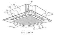
図3はこの発明の実施の形態2に係る室内機100の外観を示す図である。図3において、図1等と同じ符号を付している部材等については、実施の形態1で説明したことと同様の動作等を行う。図3において、人感センサ191は、例えば室内における人の有無等を検出するセンサ(検出器)である。
FIG. 3 is a diagram showing the appearance of the
制御装置190は、室内機100内の機器を制御する。本実施の形態においては、人感センサ191から送られる信号に基づいて、人の有無及び人がいる場合には人の位置を判断し、判断に基づいて移動させる吹き出しベーン150を決定して、その吹き出しベーン150の角度を調整し、上向きの位置に吹き出しベーン150を移動(回転)させる。
The
上述した実施の形態1では、リモートコントローラから送られる直風回避の指示に係る信号に基づいて、室内機100が有する4つの吹き出しベーン150のうち、指示された吹き出しベーン150について、上向きの位置に移動させるようにした。本実施の形態の室内機100は、人感センサ191を備え、人感センサ191の検出に基づいて、制御装置190が、上向きの位置に移動させる吹き出しベーン150を自動で判断して、位置制御し、直風回避を行うようにしたものである。
In the above-described first embodiment, based on the signal related to the direct wind avoidance instruction sent from the remote controller, the instructed blowing
各吹き出しベーン150について、吹き出し空気が人体に直接当たる範囲を規定したデータを、例えば制御装置190が有する記憶装置(図示せず)に記憶しておく。制御装置190は、人感センサ191の検出に基づいて、人の位置等を判断し、吹き出し空気が人体に直接当たる範囲に人がいると判断すると、対応する吹き出しベーン150を上向きの位置に移動させる。
For each blowing
ここで、実施の形態1において説明したように、対応する吹き出しベーン150を上向きの位置に移動させたときに、あらかじめ定めた数より多くなる場合には、対応する吹き出しベーン150を上向きの位置に移動させないように制限する。
Here, as described in the first embodiment, when the corresponding blowing
以上のように、実施の形態2の室内機100によれば、人感センサ191を有し、制御装置190が、人感センサ191の検出に基づいて決定した吹き出しベーン150を上向きの位置へ移動させるようにしたので、直風回避を自動的に行うことができ、人が意識等することなく快適な空間を実現することができる。
As described above, according to the
実施の形態3.
上述の実施の形態においては、直風回避を行うために吹き出しベーン150を移動させるようにしたが、直風回避の場合に限定するものではない。例えば、四方向カセット型の室内機100においては、ある吹き出し口132の吹き出し空気に対し、隣接する吹き出し口132からの吹き出し空気が干渉することがある。干渉した場合には、例えば室内の温度分布が一定にならないことがある。そこで、一方の吹き出し口132の吹き出しベーン150を移動させて、吹き出し空気の干渉を避けるようにしてもよい。
In the above-described embodiment, the
実施の形態4.
図4はこの発明の実施の形態4に係る空気調和装置の構成例を表す図である。ここで、図4では空気調和装置を冷凍サイクル装置の例として示している。図4において、図1等において説明したものについては、同様の動作を行うものとする。図4の空気調和装置は、室外機(室外ユニット)200と室内機(室内ユニット)100とをガス冷媒配管300、液冷媒配管400により配管接続する。室外機200は、圧縮機210、四方弁220、室外熱交換器230及び膨張弁240を有している。
4 is a diagram illustrating a configuration example of an air-conditioning apparatus according to
圧縮機210は、吸入した冷媒を圧縮して吐出する。ここで、特に限定するものではないが、圧縮機210は例えばインバータ回路等により、運転周波数を任意に変化させることにより、圧縮機210の容量(単位時間あたりの冷媒を送り出す量)を変化させることができるようにしてもよい。四方弁220は、例えば冷房運転時と暖房運転時とによって冷媒の流れを切り換える弁である。
The
本実施の形態における室外熱交換器230は、冷媒と空気(室外の空気)との熱交換を行う。例えば、暖房運転時においては蒸発器として機能し、冷媒を蒸発させ、気化させる。また、冷房運転時においては凝縮器として機能し、冷媒を凝縮して液化させる。
絞り装置(流量制御手段)等の膨張弁240は冷媒を減圧して膨張させる。例えば電子式膨張弁等で構成した場合には、前述した制御装置190等の指示に基づいて開度調整を行う。室内熱交換器110は、例えば空調対象となる空気と冷媒との熱交換を行う。暖房運転時においては凝縮器として機能し、冷媒を凝縮して液化させる。また、冷房運転時においては蒸発器として機能し、冷媒を蒸発させ、気化させる。
An
最初に、冷凍サイクル装置における冷房運転について冷媒の流れに基づいて説明する。冷房運転においては、実線で示す接続関係となるように四方弁220を切り替える。圧縮機210により圧縮されて吐出した高温、高圧のガス冷媒は、四方弁220を通過し、室外熱交換器230に流入する。そして、室外熱交換器230内を通過して、室外の空気と熱交換することで凝縮、液化した冷媒(液冷媒)は、膨張弁240へ流入する。膨張弁240で減圧されて気液二相状態となった冷媒は室外機200から流出する。
First, the cooling operation in the refrigeration cycle apparatus will be described based on the refrigerant flow. In the cooling operation, the four-
室外機200を流出した気液二相冷媒は、液冷媒配管400を通過して室内機100に流入する。そして、ディストリビュータ及び流量調整用毛細管(図示せず)により分配され、室内熱交換器110に流入する。前述したように室内熱交換器110を通過して、例えば空調対象の空気と熱交換することで蒸発、ガス化した冷媒(ガス冷媒)は、室内機100から流出する。
The gas-liquid two-phase refrigerant that has flowed out of the
室内機100から流出したガス冷媒はガス冷媒配管300を通過して室外機200に流入する。そして、四方弁220を通過して再度圧縮機210に吸入される。以上のようにして空気調和装置の冷媒が循環し、空気調和(冷房)を行う。
The gas refrigerant flowing out from the
次に暖房運転について冷媒の流れに基づいて説明する。暖房運転においては、点線で示す接続関係となるように四方弁220を切り替える。圧縮機210により圧縮されて吐出した高温、高圧のガス冷媒は、四方弁220を通過して室外機200から流出する。室外機200を流出したガス冷媒は、ガス冷媒配管300を通過して室内機100に流入する。
Next, the heating operation will be described based on the refrigerant flow. In the heating operation, the four-
室内熱交換器110を通過して、例えば空調対象の空気と熱交換することで凝縮、液化した冷媒は、ディストリビュータ及び流量調整用毛細管(図示せず)とを通過して室内機100から流出する。
The refrigerant condensed and liquefied by passing through the
室内機100から流出した冷媒は液冷媒配管400を通過して室外機200に流入する。そして、膨張弁240で減圧されて気液二相状態となった冷媒は室外熱交換器230に流入する。そして、室外熱交換器230内を通過して、室外の空気と熱交換することで蒸発、ガス化した冷媒(液冷媒)は、四方弁220を通過して再度圧縮機210に吸入される。以上のようにして空気調和装置の冷媒が循環し、空気調和(暖房)を行う。
The refrigerant flowing out from the
以上のように、実施の形態4の空気調和装置(冷凍サイクル装置)においては、上述の室内機100を用いて構成することで、直風回避をしつつ、スマッジングを低減することができる。
As described above, the air conditioner (refrigeration cycle apparatus) according to
上述の実施の形態では、室内機100は4つの吹き出し口132と吹き出しベーン150とを有し、四方向の空気を吹き出す四方向カセット型の室内機であるものとして説明したが、これに限定するものではない。例えば、二方向、三方向の空気の流れに対応する、他の天井埋め込み型の室内機についても適用することができる。また、天井埋め込み型の室内機に限らず、他の型式の室内機にも適用することができる。したがって、天井のスマッジングだけでなく、室内機の配置により、天井以外の室内壁のスマッジング低減にも対応することができる。さらに、吹き出し口132と吹き出しベーン150の数についても限定するものではない。
In the above-described embodiment, the
また、上述の実施の形態では、冷凍サイクル装置の例として空気調和装置について説明したが、これに限定するものではない。例えば冷蔵装置、冷凍装置等、他の冷凍サイクル装置にも適用することができる。また、冷凍サイクル装置だけでなく、送風機、換気装置等にも適用することができる。 In the above-described embodiment, the air conditioner has been described as an example of the refrigeration cycle apparatus. However, the present invention is not limited to this. For example, the present invention can be applied to other refrigeration cycle apparatuses such as a refrigeration apparatus and a refrigeration apparatus. Moreover, it can be applied not only to the refrigeration cycle apparatus but also to a blower, a ventilator or the like.
100 室内機、110 室内熱交換器、120 筐体、121 天板、122 側板、123 本体吸い込み口、124 本体吹き出し口、130 化粧パネル、131 グリル、132 吹き出し口、132A 外側風路壁、132B 内側風路壁、140 フィルタ、150 吹き出しベーン、151 回転軸、160 ベルマウス、170 ターボファン、180 ファンモータ、190 制御装置、191 人感センサ、200 室外機、210 圧縮機、220 四方弁、230 室外熱交換器、240 膨張弁、300 ガス冷媒配管、400 液冷媒配管。 100 indoor unit, 110 indoor heat exchanger, 120 housing, 121 top plate, 122 side plate, 123 main body inlet, 124 main body outlet, 130 decorative panel, 131 grille, 132 outlet, 132A outside air passage wall, 132B inside Air channel wall, 140 filter, 150 blowing vane, 151 rotating shaft, 160 bell mouth, 170 turbo fan, 180 fan motor, 190 control device, 191 human sensor, 200 outdoor unit, 210 compressor, 220 four-way valve, 230 outdoor Heat exchanger, 240 expansion valve, 300 gas refrigerant piping, 400 liquid refrigerant piping.
Claims (6)
該吹き出し口に設置され、回転軸を中心に回転する角度によって前記吹き出し口から吹き出す空気を偏向させる風向偏向板とを備える室内機であって、
運転時において、前記外側風路壁と前記風向偏向板との間において吹き出し空気が通過する外側風路と、前記内側風路壁と前記風向偏向板との間において前記吹き出し空気が通過する内側風路とを形成し、
前記風向偏向板は、前記吹き出し口に対向する側から前記吹き出し口を見たときに、前記吹き出し空気の流れに対して、前記風向偏向板の下流側の端部が、前記吹き出し口の前記外側風路壁側と重なって見えるように設置され、
前記外側風路壁と前記風向偏向板との間および前記内側風路壁と前記風向偏向板との間をともに狭くしたときに、前記内側風路の流路抵抗より前記外側風路の流路抵抗の方が大きく、前記空気の流れが弱まる上向きの位置となる角度に前記風向偏向板を回転可能とすることを特徴とする室内機。 A blowout port having an inner air passage wall and an outer air passage wall located on the outer side closer to the wall surface on which the indoor unit is installed than the inner air passage wall;
An indoor unit comprising a wind direction deflector installed at the outlet and deflecting air blown from the outlet according to an angle of rotation about a rotation axis;
In operation, inner wind the blowout air passes between the outer air passage balloon air passes between said outer air passage wall and the wind direction deflection plate, and the inner air passage wall and the wind direction deflector plate Form a road,
The wind direction deflecting plate has an end on the downstream side of the wind direction deflecting plate on the outside of the air outlet when the air outlet is viewed from the side facing the air outlet. It is installed so that it can be seen on the air channel wall side,
When both narrow and between the inner air-passage wall and the wind direction deflection plate and the wind direction deflector plate and the outer air duct wall, the outer air passage flow path than the flow path resistance of the inner air passage An indoor unit characterized in that the wind direction deflecting plate can be rotated at an angle that is an upward position where resistance is larger and the air flow is weakened .
前記上向きの位置に前記風向偏向板を同時に位置させる数を制限することを特徴とする請求項1に記載の室内機。 A plurality of the outlets provided with the wind direction deflecting plate;
The indoor unit according to claim 1, wherein the number of the wind direction deflecting plates that are simultaneously positioned at the upward position is limited.
人の有無及び人がいる場合の位置を検出する人感センサと、
該人感センサの検出に基づいて、前記上向きの位置に移動させる前記風向偏向板を決定する制御装置と
をさらに備えることを特徴とする請求項1〜3のいずれか一項に記載の室内機。 A plurality of the outlet and the wind direction deflector;
A human sensor for detecting the presence or absence of a person and the position when a person is present;
The indoor unit according to any one of claims 1 to 3, further comprising a control device that determines the wind direction deflecting plate to be moved to the upward position based on detection by the human sensor. .
冷媒を圧縮して吐出する圧縮機と、熱交換により前記冷媒を凝縮させる凝縮器と、凝縮に係る前記冷媒を減圧させるための絞り装置と、減圧に係る前記冷媒と空気とを熱交換して前記冷媒を蒸発させる蒸発器とを配管接続して冷媒回路を構成することを特徴とする空気調和装置。 The indoor unit according to any one of claims 1 to 5, and an outdoor unit,
A compressor compressing and discharging refrigerant, a condenser for condensing the refrigerant by heat exchange, and a stop device for vacuum the refrigerant according to the condensation, and the refrigerant and air in accordance with the vacuum heat exchange An air conditioner characterized in that a refrigerant circuit is configured by pipe connection to an evaporator for evaporating the refrigerant.
Priority Applications (8)
| Application Number | Priority Date | Filing Date | Title |
|---|---|---|---|
| JP2013257951A JP6157339B2 (en) | 2013-12-13 | 2013-12-13 | Indoor unit and air conditioner |
| AU2014362810A AU2014362810B2 (en) | 2013-12-13 | 2014-10-06 | Indoor unit and air conditioning apparatus |
| MX2016007673A MX2016007673A (en) | 2013-12-13 | 2014-10-06 | Indoor unit and air conditioning device. |
| PCT/JP2014/076657 WO2015087606A1 (en) | 2013-12-13 | 2014-10-06 | Indoor unit and air conditioning device |
| EP14869264.3A EP3081875B1 (en) | 2013-12-13 | 2014-10-06 | Indoor unit and air conditioning device |
| US15/026,998 US20160258649A1 (en) | 2013-12-13 | 2014-10-06 | Indoor unit and air-conditioning apparatus |
| CN201420766488.4U CN204373071U (en) | 2013-12-13 | 2014-12-08 | Indoor set and aircondition |
| CN201410743499.5A CN104713166B (en) | 2013-12-13 | 2014-12-08 | Indoor set and air-conditioning device |
Applications Claiming Priority (1)
| Application Number | Priority Date | Filing Date | Title |
|---|---|---|---|
| JP2013257951A JP6157339B2 (en) | 2013-12-13 | 2013-12-13 | Indoor unit and air conditioner |
Publications (3)
| Publication Number | Publication Date |
|---|---|
| JP2015114071A JP2015114071A (en) | 2015-06-22 |
| JP2015114071A5 JP2015114071A5 (en) | 2015-09-17 |
| JP6157339B2 true JP6157339B2 (en) | 2017-07-05 |
Family
ID=53370925
Family Applications (1)
| Application Number | Title | Priority Date | Filing Date |
|---|---|---|---|
| JP2013257951A Active JP6157339B2 (en) | 2013-12-13 | 2013-12-13 | Indoor unit and air conditioner |
Country Status (7)
| Country | Link |
|---|---|
| US (1) | US20160258649A1 (en) |
| EP (1) | EP3081875B1 (en) |
| JP (1) | JP6157339B2 (en) |
| CN (1) | CN104713166B (en) |
| AU (1) | AU2014362810B2 (en) |
| MX (1) | MX2016007673A (en) |
| WO (1) | WO2015087606A1 (en) |
Families Citing this family (13)
| Publication number | Priority date | Publication date | Assignee | Title |
|---|---|---|---|---|
| JP4952775B2 (en) * | 2009-11-05 | 2012-06-13 | ダイキン工業株式会社 | Air conditioner indoor unit |
| WO2016133261A1 (en) * | 2015-02-18 | 2016-08-25 | 삼성전자주식회사 | Air conditioner |
| JP6233398B2 (en) * | 2015-12-22 | 2017-11-22 | ダイキン工業株式会社 | Indoor unit of air conditioner |
| CN106123279B (en) * | 2016-08-24 | 2021-11-02 | 珠海格力电器股份有限公司 | Air conditioner indoor unit |
| JP6599022B2 (en) * | 2016-11-14 | 2019-10-30 | 三菱電機株式会社 | Air conditioner indoor unit |
| CN107192028A (en) * | 2017-06-28 | 2017-09-22 | 珠海格力电器股份有限公司 | Air conditioner, sitting and hanging type air conditioner indoor unit and control method thereof |
| CN108151257B (en) * | 2017-11-08 | 2023-08-15 | 珠海格力电器股份有限公司 | Human sense control structure, air conditioner and control method of air conditioner |
| CN111083931B (en) * | 2018-08-21 | 2021-04-06 | 日立江森自控空调有限公司 | Indoor unit of air conditioner |
| AU2019438545B2 (en) * | 2019-03-29 | 2022-12-08 | Mitsubishi Electric Corporation | Air-conditioning apparatus |
| CN111706965B (en) * | 2020-05-28 | 2022-04-19 | 青岛海尔空调器有限总公司 | Floor condensation preventing method and device for air conditioner and air conditioner |
| CN113137693B (en) * | 2021-04-08 | 2023-06-16 | 青岛海尔空调电子有限公司 | Anti-condensation control method for air conditioner and air conditioner |
| CN114135939B (en) * | 2021-11-08 | 2024-05-28 | 广东美的制冷设备有限公司 | Ceiling Machine |
| CN114593511B (en) * | 2021-11-29 | 2023-02-17 | 青岛海尔空调器有限总公司 | Method and device for controlling air outlet angle of air conditioner and terminal equipment |
Family Cites Families (18)
| Publication number | Priority date | Publication date | Assignee | Title |
|---|---|---|---|---|
| JPS63143449A (en) * | 1986-12-06 | 1988-06-15 | Daikin Ind Ltd | Air conditioner |
| JP3531282B2 (en) * | 1995-05-16 | 2004-05-24 | ダイキン工業株式会社 | Wind direction adjustment structure of ceiling embedded type air conditioner |
| JPH10325595A (en) * | 1997-05-23 | 1998-12-08 | Hitachi Ltd | Air conditioner |
| JP3858428B2 (en) * | 1998-02-24 | 2006-12-13 | 株式会社富士通ゼネラル | Ceiling suspended air conditioner |
| JP3986159B2 (en) * | 1998-05-15 | 2007-10-03 | 三菱重工業株式会社 | Air conditioner |
| JP4462389B2 (en) * | 1998-11-20 | 2010-05-12 | 株式会社富士通ゼネラル | Air conditioner |
| JP3408983B2 (en) * | 1999-01-25 | 2003-05-19 | 三菱電機株式会社 | Ceiling-mounted air conditioner |
| JP2007024345A (en) * | 2005-07-12 | 2007-02-01 | Mitsubishi Electric Corp | Air conditioner |
| CN101583831B (en) * | 2007-01-17 | 2011-12-21 | 大金工业株式会社 | Air conditioning control system |
| KR101065830B1 (en) * | 2008-12-29 | 2011-09-20 | 엘지전자 주식회사 | Ceiling type air conditioner |
| CN102597641B (en) * | 2009-09-28 | 2014-11-12 | 大金工业株式会社 | Control device |
| JP2011075168A (en) | 2009-09-30 | 2011-04-14 | Sanyo Electric Co Ltd | Air conditioner |
| JP5402488B2 (en) * | 2009-10-07 | 2014-01-29 | パナソニック株式会社 | Air conditioner |
| JP2011174693A (en) * | 2010-01-26 | 2011-09-08 | Daikin Industries Ltd | Ceiling-mounted indoor unit for air conditioning device |
| US20120055460A1 (en) * | 2010-09-02 | 2012-03-08 | Streivor Air Systems, Inc. | Internally Adjustable Damper |
| JP5923871B2 (en) * | 2011-05-31 | 2016-05-25 | ダイキン工業株式会社 | Indoor unit for air conditioner |
| JP2013104599A (en) * | 2011-11-11 | 2013-05-30 | Sharp Corp | Ion generator |
| JP5447569B2 (en) * | 2012-03-26 | 2014-03-19 | ダイキン工業株式会社 | Air conditioner heat exchanger and air conditioner |
-
2013
- 2013-12-13 JP JP2013257951A patent/JP6157339B2/en active Active
-
2014
- 2014-10-06 MX MX2016007673A patent/MX2016007673A/en unknown
- 2014-10-06 AU AU2014362810A patent/AU2014362810B2/en active Active
- 2014-10-06 EP EP14869264.3A patent/EP3081875B1/en active Active
- 2014-10-06 WO PCT/JP2014/076657 patent/WO2015087606A1/en active Application Filing
- 2014-10-06 US US15/026,998 patent/US20160258649A1/en not_active Abandoned
- 2014-12-08 CN CN201410743499.5A patent/CN104713166B/en active Active
Also Published As
| Publication number | Publication date |
|---|---|
| EP3081875A4 (en) | 2017-08-30 |
| AU2014362810B2 (en) | 2017-05-04 |
| JP2015114071A (en) | 2015-06-22 |
| US20160258649A1 (en) | 2016-09-08 |
| CN104713166B (en) | 2018-03-30 |
| WO2015087606A1 (en) | 2015-06-18 |
| EP3081875B1 (en) | 2020-12-30 |
| CN104713166A (en) | 2015-06-17 |
| MX2016007673A (en) | 2016-09-09 |
| EP3081875A1 (en) | 2016-10-19 |
Similar Documents
| Publication | Publication Date | Title |
|---|---|---|
| JP6157339B2 (en) | Indoor unit and air conditioner | |
| JP5281373B2 (en) | Air conditioner and control method thereof | |
| EP3412984B1 (en) | Indoor unit for air conditioners | |
| US11047584B2 (en) | Air conditioner | |
| JP6734624B2 (en) | Indoor unit of air conditioner | |
| JP6639654B2 (en) | Air conditioner | |
| JP2000179924A (en) | Ceiling embedded indoor unit | |
| CN210772705U (en) | Indoor unit and air conditioner | |
| JP6808065B2 (en) | Air conditioner | |
| WO2015075782A1 (en) | Air conditioner | |
| JP2017155953A (en) | Air conditioner | |
| JP5171759B2 (en) | Air conditioner | |
| JP6072671B2 (en) | Indoor unit and air conditioner | |
| JPH0432634A (en) | Air conditioner | |
| US10724759B2 (en) | Indoor unit for air-conditioning apparatus | |
| JP5195135B2 (en) | Air conditioner | |
| JP5104230B2 (en) | Air conditioner | |
| JP2022050948A (en) | Air conditioning ventilation system | |
| CN108474582B (en) | Air conditioning system | |
| JP6523787B2 (en) | Vehicle air conditioner | |
| CN204373071U (en) | Indoor set and aircondition | |
| WO2019198150A1 (en) | Air conditioner | |
| JPH05118635A (en) | Air conditioner | |
| JP2005321109A (en) | Indoor unit for air-conditioner | |
| JP2011232014A (en) | Indoor unit of air conditioner |
Legal Events
| Date | Code | Title | Description |
|---|---|---|---|
| A521 | Request for written amendment filed |
Free format text: JAPANESE INTERMEDIATE CODE: A523 Effective date: 20150729 |
|
| A621 | Written request for application examination |
Free format text: JAPANESE INTERMEDIATE CODE: A621 Effective date: 20150729 |
|
| A131 | Notification of reasons for refusal |
Free format text: JAPANESE INTERMEDIATE CODE: A131 Effective date: 20160531 |
|
| A521 | Request for written amendment filed |
Free format text: JAPANESE INTERMEDIATE CODE: A523 Effective date: 20160726 |
|
| A131 | Notification of reasons for refusal |
Free format text: JAPANESE INTERMEDIATE CODE: A131 Effective date: 20161122 |
|
| TRDD | Decision of grant or rejection written | ||
| A01 | Written decision to grant a patent or to grant a registration (utility model) |
Free format text: JAPANESE INTERMEDIATE CODE: A01 Effective date: 20170509 |
|
| A61 | First payment of annual fees (during grant procedure) |
Free format text: JAPANESE INTERMEDIATE CODE: A61 Effective date: 20170606 |
|
| R150 | Certificate of patent or registration of utility model |
Ref document number: 6157339 Country of ref document: JP Free format text: JAPANESE INTERMEDIATE CODE: R150 |
|
| R250 | Receipt of annual fees |
Free format text: JAPANESE INTERMEDIATE CODE: R250 |
|
| R250 | Receipt of annual fees |
Free format text: JAPANESE INTERMEDIATE CODE: R250 |
|
| R250 | Receipt of annual fees |
Free format text: JAPANESE INTERMEDIATE CODE: R250 |
|
| R250 | Receipt of annual fees |
Free format text: JAPANESE INTERMEDIATE CODE: R250 |