JP6157285B2 - Ink filling apparatus and ink filling method - Google Patents
Ink filling apparatus and ink filling method Download PDFInfo
- Publication number
- JP6157285B2 JP6157285B2 JP2013181555A JP2013181555A JP6157285B2 JP 6157285 B2 JP6157285 B2 JP 6157285B2 JP 2013181555 A JP2013181555 A JP 2013181555A JP 2013181555 A JP2013181555 A JP 2013181555A JP 6157285 B2 JP6157285 B2 JP 6157285B2
- Authority
- JP
- Japan
- Prior art keywords
- ink
- filling
- chamber
- decompression
- pressure
- Prior art date
- Legal status (The legal status is an assumption and is not a legal conclusion. Google has not performed a legal analysis and makes no representation as to the accuracy of the status listed.)
- Expired - Fee Related
Links
Images


Classifications
-
- B—PERFORMING OPERATIONS; TRANSPORTING
- B41—PRINTING; LINING MACHINES; TYPEWRITERS; STAMPS
- B41J—TYPEWRITERS; SELECTIVE PRINTING MECHANISMS, i.e. MECHANISMS PRINTING OTHERWISE THAN FROM A FORME; CORRECTION OF TYPOGRAPHICAL ERRORS
- B41J2/00—Typewriters or selective printing mechanisms characterised by the printing or marking process for which they are designed
- B41J2/005—Typewriters or selective printing mechanisms characterised by the printing or marking process for which they are designed characterised by bringing liquid or particles selectively into contact with a printing material
- B41J2/01—Ink jet
- B41J2/17—Ink jet characterised by ink handling
- B41J2/175—Ink supply systems ; Circuit parts therefor
- B41J2/17503—Ink cartridges
- B41J2/17506—Refilling of the cartridge
-
- B—PERFORMING OPERATIONS; TRANSPORTING
- B41—PRINTING; LINING MACHINES; TYPEWRITERS; STAMPS
- B41J—TYPEWRITERS; SELECTIVE PRINTING MECHANISMS, i.e. MECHANISMS PRINTING OTHERWISE THAN FROM A FORME; CORRECTION OF TYPOGRAPHICAL ERRORS
- B41J2/00—Typewriters or selective printing mechanisms characterised by the printing or marking process for which they are designed
- B41J2/005—Typewriters or selective printing mechanisms characterised by the printing or marking process for which they are designed characterised by bringing liquid or particles selectively into contact with a printing material
- B41J2/01—Ink jet
- B41J2/17—Ink jet characterised by ink handling
- B41J2/175—Ink supply systems ; Circuit parts therefor
- B41J2/17503—Ink cartridges
- B41J2/17513—Inner structure
-
- B—PERFORMING OPERATIONS; TRANSPORTING
- B41—PRINTING; LINING MACHINES; TYPEWRITERS; STAMPS
- B41J—TYPEWRITERS; SELECTIVE PRINTING MECHANISMS, i.e. MECHANISMS PRINTING OTHERWISE THAN FROM A FORME; CORRECTION OF TYPOGRAPHICAL ERRORS
- B41J2/00—Typewriters or selective printing mechanisms characterised by the printing or marking process for which they are designed
- B41J2/005—Typewriters or selective printing mechanisms characterised by the printing or marking process for which they are designed characterised by bringing liquid or particles selectively into contact with a printing material
- B41J2/01—Ink jet
- B41J2/17—Ink jet characterised by ink handling
- B41J2/175—Ink supply systems ; Circuit parts therefor
- B41J2/17503—Ink cartridges
- B41J2/17553—Outer structure
Landscapes
- Ink Jet (AREA)
Description
本発明は、インク収容室内にインクを充填するためのインク充填装置およびインク充填方法に関するものである。 The present invention relates to an ink filling apparatus and an ink filling method for filling the ink to Lee ink accommodating chamber.
例えば、インクジェット記録ヘッドにインクを供給するためのインクタンクとして、負圧発生部材を備えたインク収容室(第1室)と、負圧発生部材を備えないインク収容室(第2室)と、を有するものがある。前者の第1室は、インク供給口と大気連通口を備えており、内部の負圧発生部材によってインクを吸収保持することにより、インクに負圧を付与する。後者の第2室は、前者の第1室のみと連通する実質的な密閉空間を形成するものであり、その内部にインクを直接収容する。このようなインクタンクに対するインク充填方法として、インクタンク内を減圧してインクを充填する方法(減圧充填方法)が提案されている(特許文献1)。 For example, as an ink tank for supplying ink to an inkjet recording head, an ink storage chamber (first chamber) provided with a negative pressure generating member, an ink storage chamber (second chamber) not provided with a negative pressure generating member, Some have The former first chamber includes an ink supply port and an atmosphere communication port, and applies negative pressure to the ink by absorbing and holding the ink by an internal negative pressure generating member. The latter second chamber forms a substantially sealed space that communicates only with the former first chamber, and directly stores ink therein. As an ink filling method for such an ink tank, a method of filling the ink by depressurizing the inside of the ink tank (decompression filling method) has been proposed (Patent Document 1).
特許文献1に記載されている方法は、第1室内および第2室内を所定の減圧状態に保持して、第2室内および第1室内にその順序でインクを充填する。 In the method described in Patent Document 1, the first chamber and the second chamber are held in a predetermined reduced pressure state, and the second chamber and the first chamber are filled with ink in that order.
インクタンクの品質管理上の重要項目として、インク充填後にインク収容室に残る気泡の体積を小さくすることが挙げられる。それは、使用者がインクタンクを開封した際のインク漏れを防止するためである。また、インクタンクへのインクの充填方法としては、常圧のインクタンク内に対してインクを加圧して充填する加圧充填方法と、特許文献1に記載されているように、インクタンク内を減圧した後にインクを充填する減圧充填方法と、がある。 An important item in quality control of the ink tank is to reduce the volume of bubbles remaining in the ink storage chamber after ink filling. This is to prevent ink leakage when the user opens the ink tank. Further, as a method for filling ink into the ink tank, a pressure filling method in which the ink is pressurized and filled in the ink tank at normal pressure, and as described in Patent Document 1, the inside of the ink tank is filled. There is a reduced pressure filling method in which ink is filled after the pressure is reduced.
加圧充填方法は、インクタンク内に空気が存在する状態から、その空気を加圧したインクによって追い出しながらインクを充填する。そのため、インクの充填速度を高くするとインクが空気を巻き込むおそれがあり、その巻き込みが生じた場合には、インク充填後におけるインク収容室内の気泡の体積は大きくなってしまう。したがって、加圧充填方法の充填速度には制限があり、充填時間が長くなる。 In the pressure filling method, ink is filled while the air is present in the ink tank while the air is expelled by the pressurized ink. For this reason, if the ink filling speed is increased, the ink may be engulfed, and if such entanglement occurs, the volume of bubbles in the ink containing chamber after ink filling will increase. Therefore, the filling speed of the pressure filling method is limited, and the filling time becomes long.
それに対して減圧充填方法は、インクタンク内を排気した後にインクを充填するため、充填速度を高くしてもインク収容室内に残る気泡を小さくすることができる。一般に、インクタンク内の減圧工程における気圧を低くする程、インク充填完了後にインク収容室内に残る気泡の体積も小さくなる。つまり、減圧充填方法においては、気泡の体積をインクの漏れ防止が可能な大きさ以下とするために、減圧工程における気圧の管理が重要となる。 In contrast, in the reduced pressure filling method, ink is filled after the ink tank is evacuated, so that bubbles remaining in the ink containing chamber can be reduced even if the filling speed is increased. In general, the lower the air pressure in the pressure reducing process in the ink tank, the smaller the volume of bubbles remaining in the ink containing chamber after completion of ink filling. In other words, in the reduced pressure filling method, it is important to manage the atmospheric pressure in the reduced pressure step in order to keep the volume of bubbles below the size that can prevent ink leakage.
特許文献1の減圧充填方法において、複数のインクタンクに対して連続してインクを充填する場合に、インク収容室内と共に減圧されるようにインク収容室内に連通する空間(例えば、配管内の一部分)内に、インクが残ったままとなることが考えられる。そのような空間にインクが残ったまま、インク収容室内を減圧した場合には、そのインク収容室内が飽和水蒸気圧に達して、空間に残っているインクが沸騰するおそれがある。このようにインクが沸騰した場合には、インク収容室内から排気する空気中に水蒸気が大量に含まれるため、インク収容室内が減圧し難くなる。そのため、例えば、インク充填のために必要なインク収容室内の目標気圧が飽和水蒸気圧よりも低い場合には、減圧に要する時間が長くなってしまう。 In the reduced pressure filling method of Patent Document 1, when a plurality of ink tanks are continuously filled with ink, a space communicating with the ink containing chamber so as to be depressurized together with the ink containing chamber (for example, a part in a pipe) It is conceivable that the ink remains inside. If the pressure in the ink storage chamber is reduced while ink remains in such a space, the ink storage chamber may reach a saturated water vapor pressure, and the ink remaining in the space may boil. When the ink has boiled in this way, a large amount of water vapor is contained in the air exhausted from the ink containing chamber, so that it is difficult to reduce the pressure in the ink containing chamber. Therefore, for example, when the target atmospheric pressure in the ink containing chamber necessary for ink filling is lower than the saturated water vapor pressure, the time required for pressure reduction becomes long.
本発明の目的は、インク収容室内と共に減圧されるようにインク収容室内に連通する空間内にインクが残っていても、インク収納室内を目標気圧まで効率よく減圧することができるインク充填装置およびインク充填方法を提供することにある。 An object of the present invention is to provide an ink filling device and an ink that can efficiently depressurize the ink containing chamber to a target pressure even if the ink remains in a space communicating with the ink containing chamber so that the pressure is reduced together with the ink containing chamber. It is to provide a filling method.
本発明のインク充填装置は、インク収容室と、前記インク収容室内のインクを外部に供給するためのインク供給口と、前記インク収容室内を大気に連通させる連通口と、を備えるインクタンクに対してインクを充填するインク充填装置であって、前記連通口を通して前記インク収容室内を所定圧力まで減圧する減圧手段と、前記インク供給口から前記インク収容室内にインクを充填する充填手段と、前記インクの飽和水蒸気圧が前記所定圧力よりも低くなるように前記インク収容室内に連通する空間内に存在するインクを冷却するための冷却手段と、を備えることを特徴とする。 The ink filling apparatus of the present invention, the i ink accommodating chamber, the ink and the ink supply port for supplying to the outside of said ink chamber, said ink chamber and the communication port for communicating with the atmosphere, the ink tank comprising and filling means an ink filling apparatus for filling the ink, filling and depressurizing means for depressurizing the ink accommodating chamber through the communicating mouth to a predetermined pressure, the ink in the ink chamber from the ink supply port for the Cooling means for cooling the ink existing in the space communicating with the ink storage chamber so that the saturated water vapor pressure of the ink is lower than the predetermined pressure .
本発明によれば、インク収容室内と共に減圧されるようにインク収容室内に連通する空間内残っているインクを冷却することにより、インク収納室内を目標気圧まで効率よく減圧することができる。 According to the present invention, by cooling the ink remaining in the space communicating with the ink containing chamber so that the pressure is reduced together with the ink containing chamber, the ink containing chamber can be efficiently depressurized to the target pressure.
以下、本発明の実施の形態を図面に基づいて説明する。
(第1の実施形態)
まず、本実施の形態のインクタンク10の内部構造について、図1を参照して説明する。
Hereinafter, embodiments of the present invention will be described with reference to the drawings.
(First embodiment)
First, the internal structure of the
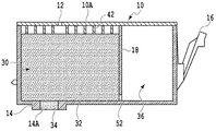
インクタンク10には、隔壁18によって仕切られた負圧発生部材収容室30とインク収容室36が形成されている。負圧発生部材収容室(以下、「第1の収容室」ともいう)30は、その上部に形成された連通口12を介して大気に連通している。第1の収容室30の下部にはインク供給口14Aが設けられており、内部には負圧発生部材としての吸収体32が収容されている。インク供給口14Aを形成するインク供給口14内には、吸収体32よりも毛管力が高くかつ物理的強度の高い圧接体34が設けられており、その圧接体34は吸収体32に圧接している。インク収容室(以下、「第2の収容室」ともいう)36は、連通部52を介して第1の収容室30のみと連通しており、実質的な密閉空間を形成している。
In the
第1の収容室30を形成するインクタンク10の上壁10Aには、第1の収容室30の内部に突出する形態の複数のリブ42が形成されており、これらのリブ42は吸収体32に当接している。インクタンク10の外側には、弾性変形可能なレバー部材16が一体に形成されており、そのレバー部材16の中間部には係止用突起が形成されている。この係止用突起が記録装置におけるインクタンク装着部の一部と係合することにより、インクタンク装着部に対してインクタンク10が交換可能に装着される。
A plurality of
(インク充填装置の基本構成)
次に、このようなインクタンク10にインクを充填するためのインク充填装置の基本構成を図2に基づいて説明する。
(Basic configuration of ink filling device)
Next, a basic configuration of an ink filling apparatus for filling the ink into the
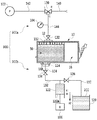
図2のインク充填装置900は、減圧ユニット900aと充填ユニット900bとを含む。減圧ユニット900aは、インクタンク上部の連通口12に接続されてインクタンク10内を減圧し、充填ユニット900bは、インクタンク下部のインク供給口14Aに接続されてインクタンク10内にインク200を充填する。減圧ユニット900aにおいては、負圧発生源としての真空ポンプ102、気圧測定計104、三方バルブ130、バルブ132、および密着部材112が配管140、142、および146によって接続されている。密着部材112は、連通口12の開口面に密着して、連通口12とバルブ132との間を連通する。充填ユニット900bにおいては、インク溜め120、シリンジ122、バルブ134、136、および密着部材114が配管150、152、および154によって接続されている。密着部材114は、インク供給口14Aの開口面に密着して、インク供給口14Aとバルブ134との間を連通する。配管140の一端とインク溜め120は、大気へ開放されている。
The
インクの充填に際しては、まず、インクタンク10を固定治具(不図示)に装着し、インク供給口14Aが下方に位置するようにインクタンク10を位置決めする。そして、密着部材112を連通口12の開口面に密着させ、また密着部材114をインク供給口14Aの開口面に密着させる。
In filling the ink, first, the
その後、減圧ユニット900aによってインクタンク10内を減圧する(減圧工程)。なお、減圧を行う真空ポンプ102は常に駆動しているものとする。三方バルブ130のポートL,C間を開き、さらにバルブ132を開けることでインクタンク10内の減圧を開始し、これにより徐々にインクタンク10内の気圧は低くなる。インクタンク10内の気圧が所定気圧(本実施例の場合は、2.0kPa)に到達したかどうかは、気圧測定計104を用いて判断する。所定気圧に到達したならば、バルブ132を閉じてインクタンク10内の減圧を止める。
Thereafter, the inside of the
その後、充填ユニット900bによってインクタンク10内にインクを充填する(充填工程)。まず、バルブ134を開けてから、モータ106によって、シリンジ122のピストン122Aを矢印A1方向に前進させる。これにより、配管152、154、および密着部材114の連通路を通して、ピストン122Aの移動量に対応する所定量のインクがインクタンク10内に充填される。このとき、バルブ132によって連通口12を閉じることにより、配管146内にインク200が流入することはない。所定量のインクを充填した後に、バルブ134を閉じる。
Thereafter, the
その後、インクタンク10内を大気に解放する(大気開放工程)。すなわち、三方バルブ130をポートL,C間の開き位置からポートR,C間の開き位置に切り換えることにより、配管140から146まで大気が流入する。さらに、バルブ132を開放することで、減圧状態にあるインクタンク10内へ大気が流入する。インクタンク10内への大気流入後に、バルブ132を閉じてから、三方バルブ130をポートR,C間の開き位置からポートL,C間の開き位置に切り換えることにより、元の減圧工程前の状態へ戻る。
Thereafter, the inside of the
インクの充填工程に先立って、シリンジ122内には、予め、インク溜め120内のインク200が導入されている。バルブ134を閉じかつバルブ136を開いた状態において、モータ106によってピストン122Aを矢印A2方向に後退させることにより、インク溜め120内のインク200がシリンジ122内に導入される。
Prior to the ink filling process, the
このようなインク充填装置900においては、複数のインクタンク10に対して連続的にインクを充填する場合が想定できる。この場合には、先の充填対象のインクタンク10内にインクを充填した後、インク供給路の一部を形成する配管154内にインクが残った状態のまま、次の充填対象のインクタンク10内が減圧されることになる。その減圧工程が進行すると、配管154内に残ったインク200が沸騰するおそれがある。図3は、インクの飽和水蒸気曲線を示し、常温の25度においては、インクの圧力が目標の2kPaに達する前の2.7kPaで飽和水蒸気圧に達して、沸騰を開始することになる。この沸騰現象のために、減圧工程において排気する空気中に水蒸気が飽和しているため、インクタンク10内の減圧が阻害されるおそれがある。一方、減圧を継続させた場合には、水分が蒸発する際の気化熱によってインク自身から熱が奪われて、インクが冷却されることになり、飽和水蒸気圧が低くなって気圧も低下する。結果的に、このような減圧を継続させることによって、所望の気圧2kPaに到達することも可能ではあるが、その所望の気圧までの減圧に要する時間は、沸騰現象のために長くなってしまう。
In such an
本実施形態においては、このような考察の基に、配管154内などの減圧される空間内に残ったインク200を積極的に冷却する。インクの温度が下がるほど飽和水蒸気圧は低下し、例えば、インクを15度まで冷却した場合には、図3のように飽和水蒸気圧が1.3kPaとなり、この気圧に達するまではインクは沸騰しない。つまり、インクを沸騰させることなく、それを目標気圧2kPaにまで到達させることができる。したがって、飽和水蒸気によってインクタンク10内の減圧が阻害されることもなくなり、減圧時間の短縮が可能となる。
In the present embodiment, the
(インク充填装置の特徴的な構成)
図4は、インクの冷却機能を備えた本実施形態のインク充填装置の構成図である。前述した図2の基本構成と同様の部分には、同一符号を付して説明を省略する。
(Characteristic configuration of ink filling device)
FIG. 4 is a configuration diagram of the ink filling apparatus of the present embodiment having an ink cooling function. The same parts as those in the basic configuration shown in FIG.
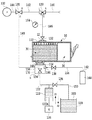
配管154内を冷却するために、配管154とバルブ134を収容する密閉容器170を備え、この密閉容器170の密閉を維持するように、密着部材114、配管148、および液体噴射装置(液体噴射部)160を取り付ける。配管148は、真空ポンプ102と三方バルブ130との間に備えられた三方バルブ131に接続される。液体噴射装置160は、バルブ138および配管156を介して、液体164で満たされた液体容器162に接続される。液体噴射装置160は、その先端から配管154に向かって液体164を噴射するように構成されている。
In order to cool the inside of the
本実施形態のインク充填装置は、前述した図2のインク充填装置と同様に、減圧工程、充填工程、および大気開放工程によってインクタンク10内にインクを充填する。図2のインク充填装置における真空ポンプ102は、減圧工程においてのみ機能するだけであり、充填工程および大気開放工程、さらにインク充填完了後のインクタンクの取り出し、および充填対象のインクタンクの位置決めのときには、能力が生かされていない。つまり、真空ポンプ102は、常に駆動されていたとしても、減圧工程の実施時以外のときは負圧の供給源として使用されていない。本実施形態においては、このような真空ポンプ102の未使用の時間を利用して、以下のように配管154を冷却する。なお、減圧工程、充填工程、および大気開放工程において、前述した図2のインク充填装置と共通する部分については説明を省略する。
In the ink filling device of the present embodiment, ink is filled into the
まず、減圧工程において、三方バルブ131のポートL,R間を開いて、前述したようにインクタンク10内を減圧する。その減圧工程の完了後に移行する充填工程および大気開放工程においては、真空ポンプ102によるインクタンク10の減圧は行わないため、三方バルブ131をポートL,R間の開き位置からポートL,C間の開き位置に切り換える。これにより、密閉容器170内によって形成される減圧室Sを減圧する。そして、この減圧室内の減圧時に、液体噴射装置160から配管154に向けて液体164を噴射して、その液体164を配管154の表面に付着させる。液体は、減圧空間において蒸発しやすいため、配管154の表面に付着した液体164の蒸発により気化熱が奪われて、配管154が冷却され、その内部のインク200が冷却される。バルブ138を開閉制御して、配管154の表面に液体164が常に付着するようにすれば、配管154内のインク200の冷却を継続することができる。液体164としては、配管154の表面に付着した後に蒸発しやすい性質をもつものが望ましい。例えば、沸点の低いエタノール等を挙げることができる。
First, in the decompression step, the ports L and R of the three-
このような冷却動作を充填工程、大気開放工程、インクタンクの取り出し、およびインクタンクの位置決めのときに実施することにより、次のインクタンクにインクを充填するときには、配管154内のインクが冷却された状態で減圧工程を開始することができる。前述したように、インクが冷却されていれば飽和水蒸気圧が低下し、目標気圧までの減圧時間の短縮が可能となる。
By carrying out such a cooling operation at the time of filling process, releasing to the atmosphere, taking out the ink tank, and positioning the ink tank, the ink in the
複数のインクタンク10に対して連続的にインクを充填する場合には、以上の動作を繰り返す。その場合、減圧工程において配管154内にインクが存在していても、そのインクを冷却することにより、インクタンク内が目標気圧に達するまでの減圧時間を短縮して、複数のインクタンクを連続的に効率よく充填することができる。
When the ink is continuously filled in the plurality of
真空ポンプ102の仕様によっては、蒸発した液体164を取り込むことが故障の発生原因となるものもあると考えられる。その場合には、三方バルブ131と密閉容器170との間に、蒸発した液体164をトラップする不図示のトラップ装置を設ければよい。また、インクの充填対象となるインクタンクは、図1のように第1および第2の収容室30,36を有するインクタンク10のみに限定されず、例えば、第1の収容室30のみを有するインクタンクに対しても減圧時間を短縮してインクを充填することができる。
Depending on the specifications of the
(第2の実施形態)
上述した第1の実施形態の充填装置において配管154を冷却する場合、限られた時間内において効率よく配管154の表面から気化熱を奪うためには、配管154の表面積を大きくして、その表面全体から液体を蒸発させる必要がある。そのため、本実施形態においては、図5に示すようなフィン(起伏部)付きの配管166を配管154の代わりに取り付ける。
(Second Embodiment)
When cooling the
フィン付きの配管166は、中空の配管本体166Aの表面に螺旋状のフィン166Bを設けた形状となっている。この配管166の材質としては、耐インク性があり、かつ熱伝導性の良い金属が望ましい。このフィン付きの配管166を配管154の代わりに取り付けることの利点としては、次の2つが挙げられる。1つの利点は、フィン166Bによって配管166の表面積が大きくなり、液体が蒸発する際に配管166から気化熱を奪いやすくなることである。他の利点は、配管166の側面に対して一方向から液体を噴射した場合でも、その液体が螺旋状のフィン166Bを伝って配管166の表面全体に満遍なく行き渡ることである。したがって、配管166の表面全体に液体を付着させるために複数方向から液体を噴射させる必要がなく、一方向からの液体の噴射でも充分であるため、装置全体のコンパクト化が可能となる。
The
また、配管154の表面の起伏部は、螺旋状のフィン166Bのみに限定されず、配管154の表面積を広くすることができる形状であればよい。配管154の表面に多孔質体を備えることによっても同様の効果を得ることができる。その多孔質体によって、配管154の表面積を広くし、かつ多孔質体の毛管現象によって液体を配管154の表面全体に行き渡らせることができるからである。配管154の表面を多孔質形状とすることができればよく、配管154の表面に多孔質体を備える他、その配管154の表面自体を多孔質形状としてもよい。
Further, the undulations on the surface of the
(第3の実施形態)
本実施形態のインク充填装置900は、使用済みのインクタンクに対するインクの再充填に適する構成となっている。図6を用いて、本実施形態のインク充填装置900について説明する。
(Third embodiment)
The
インクジェット記録装置において使用された後のインクタンク10は、第2の収容室36内にはインクが残っていないが、第1の収容室30の吸収体33内にインクが残って、その吸収体33がインクによって湿らされた状態にある。このようなインクタンク10に対して、前述と同様にインクを充填する場合にも、インクの充填完了後に残る気泡の体積を規格以内にするために、目標とするインクタンク10内の気圧を2kPa以下とする必要がある。しかし、図3から分かるように、吸収体33内のインクは、常温において2.7kPaで沸騰が生じてしまう。その沸騰が生じた場合には、インクタンク10内の減圧が阻害され、その結果、減圧に要する時間が長くなってしまう。
In the
そこで本実施形態においては、インク充填装置900全体を体温状態の低温空間180内に収容することによって、吸収体33内に残ったインクを冷却する。このように、吸収体33内に残ったインクを冷却することにより、インクの飽和水蒸気圧を低下させて、沸騰の発生を遅らせることができる。本例の場合は、目標気圧を2kPaとしているため、図3から分かるように、低温空間180の気温を20度以下にすることが望ましい。このような低温空間180内の低温環境下において、前述したようにインクタンクに対してインクを充填することにより、減圧工程においてインクを沸騰させることなくインクタンク内を目標気圧まで減圧させることができる。この結果、減圧に要する時間を短くして、使用済みのインクタンクに対してインクを効率よく再充填することができる。
Therefore, in the present embodiment, the
また、一般的に、使用済みのインクタンクにインクを再充填する場合には、インクタンク10の第2の収容室36をインクで満たすために、その第2の収容室36に新たにインクの注入穴を開けることが必要となる。しかし、本実施形態においては、このようなインクタンクに加工を施すことなく、インクを再充填することが可能である。
In general, when refilling a used ink tank with ink, in order to fill the
(他の実施形態)
前述した実施形態においては、バルブ134とインク供給口14Aとの間の配管154内に残ったインクを冷却する構成となっている。しかし、冷却対象のインクは、インク収容室内と共に減圧されるようにインク収容室内に連通する空間内に存在するインクであればよく、配管154内のインクのみに限定されない。また、そのような空間を形成する部材は、配管のみに限定されない。
(Other embodiments)
In the embodiment described above, the ink remaining in the
インク供給口14Aは、第1の収容室30内のインクを外部に直接的または間接的に供給することができればよく、必ずしも第1の収容室30に設けられていなくてもよい。連通口12は、第1の収容室30内を大気に直接的または間接的に連通させることができればよく、必ずしも第1の収容室30に設けられていなくてもよい。上述した実施形態における連通口12は、インクタンク10内のインクをインク供給口14Aからインクジェット記録ヘッドなどの外部に供給する際に、インクタンク10内を大気に連通する大気連通口として機能する。しかし、連通口12は、インク充填のためにインクタンク10内を減圧するときにのみ機能するものであってもよい。つまり、連通口12は、インクタンク10内のインクを外部に供給する際に機能する大気連通口とは別に設けてもよい。
The
10 インクタンク
12 連通口
14A インク供給口
30 負圧発生部材収容室(第1の収容室)
32 吸収体(負圧発生部材)
102 真空ポンプ(負圧発生源)
160 液体噴射装置(液体噴射部)
S 減圧室
DESCRIPTION OF
32 Absorber (negative pressure generating member)
102 Vacuum pump (negative pressure source)
160 Liquid ejector (liquid ejector)
S decompression chamber
Claims (13)
前記連通口を通して前記インク収容室内を所定圧力まで減圧する減圧手段と、
前記インク供給口から前記インク収容室内にインクを充填する充填手段と、
前記インクの飽和水蒸気圧が前記所定圧力よりも低くなるように前記インク収容室内に連通する空間内に存在するインクを冷却するための冷却手段と、
を備えることを特徴とするインク充填装置。 And Lee ink storage chamber, an ink supply port for supplying ink of the ink accommodating chamber to the outside, the ink filling for filling the ink the ink chamber to the ink tank comprising: a communication port for communicating with the atmosphere, the A device,
Decompression means for decompressing the ink containing chamber to a predetermined pressure through the communication port;
Filling means for filling ink into the ink containing chamber from the ink supply port;
Cooling means for cooling the ink existing in the space communicating with the ink containing chamber so that the saturated water vapor pressure of the ink is lower than the predetermined pressure ;
An ink filling device comprising:
前記冷却手段は、前記インク収容室内と共に減圧される前記インク供給路の部分に存在するインクを冷却する請求項1に記載のインク充填装置。 The filling means fills the ink storage chamber with ink from the ink supply port through an ink supply path,
It said cooling means, an ink filling apparatus according to 請 Motomeko 1 you cool ink present in the portion of the ink supply channel is depressurized together with the ink storage chamber.
前記連通口を通して前記インク収容室内を所定圧力まで減圧する減圧工程と、
前記減圧工程によって前記インク収容室内が減圧された後に、前記インク供給口から前記インク収容室内にインクを充填する充填工程と、
前記減圧工程の前に、前記インクの飽和水蒸気圧が前記所定圧力よりも低くなるように前記インク収容室内に連通する空間内に存在するインクを冷却する冷却工程と、
を含むことを特徴とするインク充填方法。 And Lee ink storage chamber, an ink supply port for supplying ink of the ink accommodating chamber to the outside, the ink filling for filling the ink the ink chamber to the ink tank comprising: a communication port for communicating with the atmosphere, the A method,
A depressurization step of depressurizing the ink containing chamber to a predetermined pressure through the communication port;
A filling step of filling ink into the ink containing chamber from the ink supply port after the ink containing chamber has been depressurized by the depressurizing step;
Before the pressure reducing step, cooling the ink existing in the space communicating with the ink containing chamber so that the saturated water vapor pressure of the ink is lower than the predetermined pressure ;
An ink filling method comprising:
前記冷却工程において、前記空間を形成する部材を収容して減圧される減圧室内に、気化熱によって前記部材を冷却するための液体を噴射し、かつ前記減圧工程の実施時以外のときに前記負圧発生源から前記減圧室内に負圧を導入する請求項10に記載のインク充填方法。 The decompression step decompresses the ink storage chamber by introducing a negative pressure from a negative pressure generation source,
In the cooling step, a liquid for cooling the member is sprayed by heat of vaporization into a decompression chamber that accommodates the member forming the space and is decompressed, and the negative is performed at a time other than when the decompression step is performed. The ink filling method according to claim 10 , wherein a negative pressure is introduced into the decompression chamber from a pressure generation source.
前記冷却工程は、少なくとも前記第2のインクタンクに対する前記減圧工程の前までに、前記第1のインクタンクに対する前記充填工程によって前記空間内に残されたインクを冷却する請求項10または11に記載のインク充填方法。 After performing the decompression step and the filling step on the first ink tank, the decompression step and the filling step are carried out on the second ink tank,
The cooling step and before the depressurization step to at least said second ink tank, according to claim 10 or 11 for cooling the ink left in the space by the filling process for the first ink tank Ink filling method.
Priority Applications (2)
| Application Number | Priority Date | Filing Date | Title |
|---|---|---|---|
| JP2013181555A JP6157285B2 (en) | 2013-09-02 | 2013-09-02 | Ink filling apparatus and ink filling method |
| US14/458,109 US9102160B2 (en) | 2013-09-02 | 2014-08-12 | Ink filling apparatus and ink filling method |
Applications Claiming Priority (1)
| Application Number | Priority Date | Filing Date | Title |
|---|---|---|---|
| JP2013181555A JP6157285B2 (en) | 2013-09-02 | 2013-09-02 | Ink filling apparatus and ink filling method |
Publications (3)
| Publication Number | Publication Date |
|---|---|
| JP2015047793A JP2015047793A (en) | 2015-03-16 |
| JP2015047793A5 JP2015047793A5 (en) | 2016-09-15 |
| JP6157285B2 true JP6157285B2 (en) | 2017-07-05 |
Family
ID=52582638
Family Applications (1)
| Application Number | Title | Priority Date | Filing Date |
|---|---|---|---|
| JP2013181555A Expired - Fee Related JP6157285B2 (en) | 2013-09-02 | 2013-09-02 | Ink filling apparatus and ink filling method |
Country Status (2)
| Country | Link |
|---|---|
| US (1) | US9102160B2 (en) |
| JP (1) | JP6157285B2 (en) |
Families Citing this family (4)
| Publication number | Priority date | Publication date | Assignee | Title |
|---|---|---|---|---|
| US10479100B2 (en) | 2015-07-31 | 2019-11-19 | Hewlett-Packard Development Company, L.P. | Printer with an air pressurization system and method of building up air pressure in a printing fluid supplier |
| CN105711262B (en) * | 2015-12-25 | 2017-07-14 | 北海绩迅电子科技有限公司 | The ink-joiner and refilling method of a kind of ink horn of regeneration |
| JP2018103491A (en) * | 2016-12-27 | 2018-07-05 | ブラザー工業株式会社 | Waste liquid tank and liquid discharge device |
| JP7451163B2 (en) * | 2019-12-13 | 2024-03-18 | キヤノン株式会社 | Image recording device, control method and program for the image recording device |
Family Cites Families (11)
| Publication number | Priority date | Publication date | Assignee | Title |
|---|---|---|---|---|
| JPS55132264A (en) * | 1979-04-02 | 1980-10-14 | Canon Inc | Liquid-drip jet recording device |
| JPH03287791A (en) | 1990-04-05 | 1991-12-18 | Youhou Sangyo Kk | Method for preventing corrosion of carrier car |
| JPH10230623A (en) * | 1997-02-21 | 1998-09-02 | Hitachi Koki Co Ltd | Method and apparatus for removing bubble from ink jet printer employing thermally fusible ink |
| JP3287791B2 (en) | 1997-07-30 | 2002-06-04 | キヤノン株式会社 | Liquid filling method and liquid filling device for liquid container having liquid container |
| JP2000015829A (en) * | 1998-06-30 | 2000-01-18 | Canon Inc | Method for injecting liquid, and liquid-injecting apparatus where the method is used |
| RU2163218C2 (en) * | 1998-11-03 | 2001-02-20 | Самсунг Электроникс Ко., Лтд. | Method of injection or working liquid into microinjection device |
| WO2002028715A1 (en) * | 2000-10-06 | 2002-04-11 | Nu-Kote International Inc | Pressurized ink filling method for dual compartment ink-jet cartridge used in ink-jet printer |
| US8172380B2 (en) * | 2007-10-01 | 2012-05-08 | Brother Kogyo Kabushiki Kaisha | Dual chamber, liquid apparatus having liquid permeability |
| JP2012081591A (en) * | 2010-10-06 | 2012-04-26 | Olympus Corp | Ink-jet printer |
| JP5804727B2 (en) | 2011-02-25 | 2015-11-04 | キヤノン株式会社 | Method and apparatus for manufacturing liquid storage container |
| JP5780785B2 (en) | 2011-03-11 | 2015-09-16 | キヤノン株式会社 | Negative pressure generating member insertion method and negative pressure generating member insertion device |
-
2013
- 2013-09-02 JP JP2013181555A patent/JP6157285B2/en not_active Expired - Fee Related
-
2014
- 2014-08-12 US US14/458,109 patent/US9102160B2/en not_active Expired - Fee Related
Also Published As
| Publication number | Publication date |
|---|---|
| US20150062259A1 (en) | 2015-03-05 |
| US9102160B2 (en) | 2015-08-11 |
| JP2015047793A (en) | 2015-03-16 |
Similar Documents
| Publication | Publication Date | Title |
|---|---|---|
| JP6157285B2 (en) | Ink filling apparatus and ink filling method | |
| JP4767743B2 (en) | Gas cooling method for high pressure fuel storage tanks on vehicles operating with compressed natural gas or hydrogen | |
| JP2015077731A (en) | Ink filling device and ink filling method | |
| US10473405B2 (en) | System and method for cooling a body | |
| JP2015047793A5 (en) | ||
| JP2005028859A (en) | Drip type ink refilling unit, ink refilling method and refilling kit | |
| JP5123703B2 (en) | Heat pipe manufacturing method and heat pipe | |
| CN103240998B (en) | A kind of method injecting ink to print cartridge | |
| JP2006207925A (en) | Carbon dioxide gas filling device | |
| CN110381701B (en) | Spray cooling device with combined steam cavity and composite microstructure | |
| JP2016515852A5 (en) | ||
| JP2009061761A5 (en) | ||
| JP5975421B2 (en) | Reversing stamp | |
| JP2004061080A (en) | Manufacturing method for heat pipe | |
| JP2015009470A5 (en) | ||
| CN109911226B (en) | Self-adaptive temperature control system | |
| KR200426477Y1 (en) | Vaporizer | |
| JP4173743B2 (en) | Fuel vapor treatment equipment | |
| JP2015093453A (en) | Liquid discharge head and method for manufacturing the same | |
| KR20200076212A (en) | Heat conduction system for cooling exothermic parts using slit structure | |
| JP2015185601A5 (en) | ||
| JP2009131784A (en) | Vapor cleaning/drying device, vapor cleaning/drying method using the same | |
| JP5414446B2 (en) | Method for manufacturing liquid storage container | |
| JP2023161426A (en) | Hydrogen charging device, hydrogen charging system and hydrogen charging method | |
| JP2015098132A (en) | Liquid filling method and liquid filling device |
Legal Events
| Date | Code | Title | Description |
|---|---|---|---|
| A521 | Request for written amendment filed |
Free format text: JAPANESE INTERMEDIATE CODE: A523 Effective date: 20160728 |
|
| A621 | Written request for application examination |
Free format text: JAPANESE INTERMEDIATE CODE: A621 Effective date: 20160728 |
|
| A977 | Report on retrieval |
Free format text: JAPANESE INTERMEDIATE CODE: A971007 Effective date: 20170418 |
|
| TRDD | Decision of grant or rejection written | ||
| A01 | Written decision to grant a patent or to grant a registration (utility model) |
Free format text: JAPANESE INTERMEDIATE CODE: A01 Effective date: 20170509 |
|
| A61 | First payment of annual fees (during grant procedure) |
Free format text: JAPANESE INTERMEDIATE CODE: A61 Effective date: 20170606 |
|
| R151 | Written notification of patent or utility model registration |
Ref document number: 6157285 Country of ref document: JP Free format text: JAPANESE INTERMEDIATE CODE: R151 |
|
| LAPS | Cancellation because of no payment of annual fees |