JP6155183B2 - Narrow groove laser welding method - Google Patents
Narrow groove laser welding method Download PDFInfo
- Publication number
- JP6155183B2 JP6155183B2 JP2013266375A JP2013266375A JP6155183B2 JP 6155183 B2 JP6155183 B2 JP 6155183B2 JP 2013266375 A JP2013266375 A JP 2013266375A JP 2013266375 A JP2013266375 A JP 2013266375A JP 6155183 B2 JP6155183 B2 JP 6155183B2
- Authority
- JP
- Japan
- Prior art keywords
- welding
- groove
- weld bead
- laser
- weld
- Prior art date
- Legal status (The legal status is an assumption and is not a legal conclusion. Google has not performed a legal analysis and makes no representation as to the accuracy of the status listed.)
- Active
Links
Images


Description
本発明は、被溶接材の溶接部位に狭開先を形成し、狭開先内にレーザ光を導光して集光照射し、狭開先内のレーザ光の照射部に溶接ワイヤを供給しながら開先部を積層溶接する狭開先レーザ溶接方法に関する。 In the present invention, a narrow groove is formed at a welding portion of a material to be welded, a laser beam is guided into the narrow groove and condensed and irradiated, and a welding wire is supplied to a laser beam irradiation portion in the narrow groove. The present invention relates to a narrow groove laser welding method in which a groove portion is laminated and welded.
レーザ溶接は、熱源のレーザビームのエネルギー密度が高いため、通常のアーク溶接に比べ、深い溶込みが得られる。さらに、低歪み、高速度、高精度の溶接継手が得られることから、現在各分野で使用されている。 In laser welding, since the energy density of the laser beam of the heat source is high, deep penetration can be obtained as compared with ordinary arc welding. Furthermore, since a welded joint with low distortion, high speed and high accuracy can be obtained, it is currently used in various fields.
レーザ溶接は、溶け込みが深く、溶接金属の凝固速度が速い。このため、溶接金属内部の中央部に、溶接欠陥(例えば、凝固割れ等の溶接割れや、溶接ビードと被溶接材との融合不良)が生じやすいという難点を有する。また、厚さ25mmを超える厚板を被溶接部材とする溶接においては、被溶接材の突き合わせ部に狭開先を形成し、狭開先内にレーザ光を導光して集光照射し、狭開先内のレーザ光の照射部に溶接ワイヤを供給しながら開先部を積層溶接する方法が行われている。レーザ溶接の溶接割れは一般的に溶接金属内部に生じることが多い。このため、溶接割れの有無を溶接後すぐ目視検査等で判断することができないので、溶接終了後に、放射線透過試験(Radiographic Testing:RT)や超音波探傷試験(Ultrasonic Testing:UT)等により溶接割れ発生の有無を確認する検査が行われている。溶接割れが発見された場合、溶接金属内部に生じた割れを除去し、補修溶接を行い、健全な溶接継手を確保する方法がとられているが、RTやUT等の検査や補修溶接作業に多くの工数を必要とする。 Laser welding has a deep penetration and a fast solidification rate of the weld metal. For this reason, it has the difficulty that a welding defect (for example, welding cracks, such as a solidification crack, and the fusion defect of a weld bead and a to-be-welded material) tends to arise in the center part inside a weld metal. Further, in welding using a thick plate having a thickness of more than 25 mm as a member to be welded, a narrow groove is formed at the butt portion of the material to be welded, and laser light is guided into the narrow groove and focused and irradiated. A method of laminating and welding a groove portion while supplying a welding wire to a laser beam irradiation portion in a narrow groove is performed. Laser welding weld cracks generally occur inside the weld metal. For this reason, since the presence or absence of weld cracks cannot be determined by visual inspection or the like immediately after welding, weld cracking is performed by a radiographic test (RT), an ultrasonic flaw test (Ultrasonic Testing: UT), or the like after the end of welding. Inspections are performed to confirm the occurrence. If a weld crack is found, a method of removing the crack generated inside the weld metal, repair welding, and securing a sound welded joint is taken, but for inspection and repair welding work such as RT and UT Requires a lot of man-hours.
このため、溶接金属内部に溶接割れ等の溶接欠陥を生じさせない健全な継手が得られる溶接技術や仮に溶接割れが起きても、溶接割れは表面に開口し、確認または検出し易い溶接技術が必要とされている。 For this reason, it is necessary to have a welding technique that can produce a sound joint that does not cause weld defects such as weld cracks inside the weld metal, or even if weld cracks occur, the weld cracks open to the surface and easy to check or detect. It is said that.
特開2013‐128938号公報(特許文献1)には、レーザ溶接を用いた薄板(板厚0.5mm〜3.2mm)のフランジ端部重ね溶接方法において、溶接部の凝固過程で、等軸晶を溶融池内に生成させることにより溶接時の凝固割れを抑制することを特徴とするレーザ溶接方法が開示されている。この方法は、薄板の重ねワンパス溶接である。 In JP 2013-12938A (Patent Document 1), in a flange end lap welding method of a thin plate (plate thickness 0.5 mm to 3.2 mm) using laser welding, in the solidification process of the welded portion, equiaxed There is disclosed a laser welding method characterized by suppressing solidification cracking during welding by generating crystals in a molten pool. This method is a one-pass welding of thin plates.
特開平9‐201687号公報(特許文献2)には、溶接の作業効率の向上を図るため、被溶接部を狭い開先幅に設定しフィラーワイヤを供給しつつレーザトーチからレーザビームを上記狭い開先幅を通して上記フィラーワイヤの部分に照射し、積層溶接することを特徴とする狭開先レーザ溶接方法が開示されている。 Japanese Patent Application Laid-Open No. 9-201687 (Patent Document 2) discloses a method for improving the welding work efficiency by setting the welded portion to a narrow groove width and supplying a filler wire to the laser beam from the laser torch. A narrow gap laser welding method is disclosed in which the filler wire is irradiated through the tip width and laminated welding is performed.
特開平7‐323386号公報(特許文献3)には、欠陥発生の抑制を目的とし、レーザを用いた厚板の溶接において、レーザビームの焦点位置をルートフェース上より焦点距離の1/20以上離してビームを照射し、溶加材としてフラックスコアードワイヤを使用することを特徴とし、1層目は完全溶込溶接とし、2層目以上は焦点位置を前層ビード上より焦点距離の1/20以上離してビームを照射し、2層目以上に使用する溶加材としてフラックスコアードワイヤを使用して多層溶接することを特徴とするレーザ溶接方法が開示されている。この方法は、1層目は完全溶込溶接とし、2層目以上は焦点位置を大きく離してビームを照射し、熱伝導型のレーザ溶接条件を用い溶接することを特徴とする。 Japanese Patent Application Laid-Open No. 7-323386 (Patent Document 3) describes the purpose of suppressing the occurrence of defects. In welding of a thick plate using a laser, the focal position of a laser beam is 1/20 or more of the focal length from the root face. It is characterized by using a flux cored wire as a filler material, and the first layer is completely penetration welded. The second layer and higher layers are focused at a focal length of 1 on the front layer bead. A laser welding method is disclosed, in which a beam is irradiated at a distance of / 20 or more and multilayer welding is performed using a flux cored wire as a filler material used in the second layer or more. This method is characterized in that the first layer is completely penetration welded, and the second and higher layers are irradiated with a beam with the focal point position greatly separated, and welding is performed using heat conduction type laser welding conditions.
特許第3671544号(特許文献4)には、50重量%以上の鉄、および0.2重量%以上の炭素、または0.045重量%以上の硫黄、または0.04重量%以上のりんを含有する鉄・炭素鋼材料、およびクロム当量とニッケル当量の比Creq/Nieqが1.48以下のステンレス鋼から選ばれた複数の板材を重ね合わせ、これに酸素ガス含有量を5〜50容量%に調整しているアシストガスを吹きつけながら、レーザビームを照射して、溶接部におけるW/L比(但しWは溶融部のビード幅を表し、Lは前記複数の板材の接合部の幅を表す)を、1.0〜1.5の範囲にコントロールすることを特徴とするレーザ溶接方法が開示されている。この溶接方法は重ねワンパス溶接であり、本発明の狭開先多層盛レーザ溶接とは異なる。 Patent No. 3671544 (Patent Document 4) contains 50% or more iron and 0.2% or more carbon, or 0.045% or more sulfur, or 0.04% or more phosphorus. And a plurality of plate materials selected from stainless steel having a ratio of chromium equivalent to nickel equivalent Cr eq / Ni eq of 1.48 or less, and an oxygen gas content of 5 to 50 volumes. While the assist gas adjusted to% is blown, the laser beam is applied to the W / L ratio in the welded portion (W represents the bead width of the melted portion, and L is the width of the joint portion of the plurality of plate members) Is represented in a range of 1.0 to 1.5. A laser welding method is disclosed. This welding method is lap one-pass welding, which is different from the narrow groove multi-layer laser welding of the present invention.
特許文献1には、溶接金属の成分の制御によって溶接金属の中央部に等軸晶を生成させることにより溶接時の凝固割れを抑制することが記載されているが、厚板の狭開先レーザ多層溶接方法ではなく、薄板重ねワンパスレーザ溶接方法である。また、溶接成分を制御しないで、溶接プロセス制御の観点で溶接割れを抑制する方法については記載されていない。 Japanese Patent Application Laid-Open No. H10-228707 describes that the control of the components of the weld metal causes the formation of equiaxed crystals at the center of the weld metal to suppress solidification cracking during welding. It is not a multilayer welding method but a thin plate one-pass laser welding method. Moreover, it does not describe a method for suppressing weld cracking from the viewpoint of welding process control without controlling the welding components.
特許文献4には、溶接割れを防止するため、アシストガスに酸素を含有するガスを用いてレーザ溶接部におけるW/L比を1.0〜1.5の範囲にコントロールすることが開示されているが、突き合わせ溶接であり、開先内にレーザを照射し、照射部にフィラーワイヤを供給しながら積層溶接する場合の溶接欠陥の発生を抑制する方法については記載されていない。
特許文献2および特許文献3には、狭開先内にレーザを照射し多層溶接する方法が開示されている。特許文献2には溶接欠陥の発生の防止あるいは抑制方法については記載されていない。特許文献3には被溶接材の溶融不良による溶接欠陥(融合不良)を防止し無欠陥の溶接継ぎ手を得る方法が開示されているが、溶接割れの発生の防止あるいは抑制方法については記載されていない。
本発明は、上記の課題に鑑みてなされたものであり、溶接割れ及び融合不良を抑制することが可能な狭開先レーザ溶接方法を提供することにある。 This invention is made | formed in view of said subject, and is providing the narrow groove laser welding method which can suppress a weld crack and a fusion defect.
本発明は、上記目的を達成するため、
被溶接材を突き合わせて狭開先を形成し、前記狭開先内にレーザ光を導光して集光照射し、前記狭開先内の前記レーザ光の照射部に溶接ワイヤを送給しつつ前記溶接ワイヤ及び前記被溶接材を溶融させて溶接ビードを形成し、前記溶接ビードを多層積層して被溶接材の積層溶接を行う狭開先レーザ溶接方法において、
前記狭開先の開先幅は2mm以上4mm以下であり、
2層目以降の前記溶接ビードの形成の際、
前記レーザ光を、前記照射部における前記レーザ光の照射幅Sと前記照射部の開先底幅Wとの比S/Wが1/4以上3/4以下となるように照射し、
且つ、前記溶接ビードの溶込み形状を、前記溶接ビードの積層高さDと下層溶接ビードへの溶込み深さPの和である溶け込み高さHと、前記溶接ビードの開先幅方向の溶込みの最大幅WMとの比H/WMが1.5以上2.5以下となるように溶接条件を制御することを特徴とする狭開先レーザ溶接方法を提供する。
In order to achieve the above object, the present invention
The material to be welded is abutted to form a narrow groove, a laser beam is guided into the narrow groove and focused and irradiated, and a welding wire is fed to the laser beam irradiation portion in the narrow groove. In the narrow groove laser welding method of melting the welding wire and the welded material to form a weld bead, and laminating the weld bead to laminate the welded material,
The groove width of the narrow groove is 2 mm or more and 4 mm or less,
When forming the weld bead after the second layer,
Irradiating the laser beam so that a ratio S / W of the irradiation width S of the laser beam and the groove bottom width W of the irradiation unit is 1/4 or more and 3/4 or less,
And the penetration shape of the said weld bead is the penetration height H which is the sum of the lamination | stacking height D of the said weld bead, and the penetration depth P to a lower layer weld bead, and the melt width direction of the said weld bead. Provided is a narrow groove laser welding method characterized by controlling the welding conditions so that the ratio H / WM to the maximum width WM of the welding is 1.5 or more and 2.5 or less.
本発明によれば、溶接割れ及び融合不良を抑制することが可能な狭開先レーザ溶接方法を提供することができる。 According to the present invention, it is possible to provide a narrow groove laser welding method capable of suppressing welding cracks and poor fusion.
(本発明の基本思想)
狭開先レーザ溶接方法は、原子力発電プラント等の大型構造物に使用される、板の厚さが25mmを超える厚板のステンレス鋼の溶接に用いられる方法である。
(Basic idea of the present invention)
The narrow groove laser welding method is a method used for welding thick stainless steel plates having a plate thickness of more than 25 mm, which is used for large structures such as nuclear power plants.
図1は狭開先レーザ溶接の工程の1部を模式的に示す図である。図1に示すように、まず被溶接材100(101a及び101b)の突き合わせ部に狭開先102を形成する。図示されていないレーザ発振器から発振されたレーザ光は、光ファイバー8により伝送され加工ヘッド7に送られる。加工ヘッド7でレンズにより集光されたレーザ光4は被溶接部材101aと101bにより形成された狭開先102内に導光されて集光照射され、被溶接材101a、101b及び溶接ワイヤ(フィラーワイヤ)3を溶融し、溶融プール9を形成しながら溶接を行い溶接ビード5を形成し、溶接ビード5を多層積層して開先部を埋めて行われる。
FIG. 1 is a diagram schematically showing a part of the narrow groove laser welding process. As shown in FIG. 1, first, a
溶接ワイヤ3は溶接方向前方から溶融プール9内に送給される。溶融プール9及びその近傍は、シールドガスノズル6から噴出されたシールドガスによりシールドされる。
The
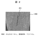
上記狭開先レーザ溶接では、下部の溶接ビードの表面、開先壁の側面および溶接ワイヤを安定的に溶融させるために、レーザ光4は焦点位置をずらしたデフォーカス条件で照射される。しかし、積層部の溶接ビードの溶け込み形状におけるH/WM比(Hは溶接ビードの溶け込み高さを表し、溶接ビードの積層高さと下部ビードへの溶込み深さの和であり、WMは溶接ビードの開先幅方向の溶込みの最大幅を表す)が1以上になると、図2に示したように溶接金属(溶接ビード)200の中央に凝固割れ201(図2中黒い部分)が生じるという問題がある。
In the narrow groove laser welding, in order to stably melt the surface of the lower weld bead, the side surface of the groove wall, and the welding wire, the
一般に溶接割れを抑制するためには、溶接ワイヤを添加し溶接金属のフェライト量を増加させることが有効といわれているが、狭開先溶接では、一般のV型開先等に比べ被溶接材の希釈率が高いので、被溶接材のCr当量/Ni当量が1.40以下のオーステナイト系ステンレス鋼に対してはワイヤの添加のみでは溶接割れの発生を防止することが困難である。また、Cr当量/Ni当量が低くなると、溶融金属の凝固も不安定となりやすく、溶接割れとともに融合不良を生じやすくなる。 In general, in order to suppress weld cracking, it is said that it is effective to add a welding wire to increase the ferrite content of the weld metal. However, in narrow groove welding, the welded material compared to general V-shaped grooves, etc. Therefore, it is difficult to prevent the occurrence of weld cracking only by adding a wire to an austenitic stainless steel having a Cr equivalent / Ni equivalent of 1.40 or less. Moreover, when Cr equivalent / Ni equivalent becomes low, solidification of the molten metal tends to be unstable, and fusion defects are likely to occur together with weld cracks.
本発明者らは、狭開先レーザ溶接方法において、溶接金属の成分を制御することなく溶接欠陥を抑制することが可能な溶接方法の条件について鋭意検討した。その結果、レーザ光の照射幅Sと照射部の開先底幅Wとの比S/Wと、溶接ビードの溶け込み高さHと溶接ビードの開先幅方向の溶込みの最大幅WMとの比H/WMを一定の範囲に制御することで、溶接欠陥を抑制することが可能であることを見出した。本発明は、該知見に基づくものである。 The present inventors diligently studied the conditions of a welding method capable of suppressing welding defects without controlling the components of the weld metal in the narrow groove laser welding method. As a result, the ratio S / W between the irradiation width S of the laser beam and the groove bottom width W of the irradiated portion, the penetration height H of the weld bead, and the maximum penetration width WM of the weld bead in the groove width direction. It has been found that welding defects can be suppressed by controlling the ratio H / WM within a certain range. The present invention is based on this finding.
以下、本発明の実施形態を図面を用いて詳細に説明する。ただし、以下の説明は本発明の内容の具体例を示すものであり、本発明はこれらの説明に限定されるものではなく、本明細書に開示される技術的思想の範囲内において当業者による様々な変更および改良が可能である。 Hereinafter, embodiments of the present invention will be described in detail with reference to the drawings. However, the following explanation shows specific examples of the contents of the present invention, and the present invention is not limited to these explanations, and is within the scope of the technical idea disclosed in the present specification by those skilled in the art. Various changes and improvements are possible.
本発明に係る狭開先レーザ溶接方法は、上述した図1に示した態様で実施することができる。図1には示していないが、レーザ発振器、ワイヤ送給制御装置、ガス流量制御装置及び溶接マニピュレータは溶接制御装置に接続されており、レーザ出力、レーザ光の焦点はずし距離、溶接速度及びワイヤ送給速度等の溶接条件並びに動作タイミング等が制御される。 The narrow groove laser welding method according to the present invention can be carried out in the mode shown in FIG. Although not shown in FIG. 1, the laser oscillator, the wire feed control device, the gas flow rate control device, and the welding manipulator are connected to the welding control device, and the laser output, the laser beam defocusing distance, the welding speed, and the wire feed rate. Welding conditions such as feed rate and operation timing are controlled.
レーザ光4としては、設備の小型化が可能で、高品質の溶接部が得られ易いファイバーレーザ、ディスクレーザ等のファイバー伝送が可能な波長が1μm程度のレーザを用いることが好ましい。CO2レーザのように発振波長の長いレーザの場合、溶接装置が大型となると共にプラズマが発生しやすいため溶接部に欠陥を生じやすく好ましくない。
As the
レーザ加工ヘッド7は、図示していない溶接マニピュレータに搭載され、直線溶接が出来るように構成されている。本発明のような開先幅の狭い(2mm以上4mm以下)狭開先溶接では、溶込み形状に及ぼす溶接姿勢の影響は小さいことから、溶接姿勢は特に限定されないが、下向きおよび横向き姿勢で実施することが好ましい。
The
図3は本発明に係る狭開先レーザ溶接方法が適用される被溶接材の1例を示す斜視模式図であり、図4は図3の正面図である。図3及び図4に示したように、本発明に係る狭開先レーザ溶接方法では、被溶接材1aと1bを突き合わせて狭開先2を形成し、突き合せ溶接を行う。被溶接材1a、1bとしては特に限定は無いが、本発明は原子力プラント等の構造物に使用される、板厚が25mm以上で材料成分から算出されるCr当量/Ni当量が1.31以上1.40以下のオーステナイト系ステンレス鋼の溶接に好適である。そのような被溶接材として、例えば板厚30mmのオーステナイト系ステンレス鋼SUS316Lを用いることができる。SUS316Lは、ディロングの組織図(Cr当量:Cr+Mo+1.5×Si+0.5×Nb、Ni当量:Ni+30×C+30×N+0.5×Mn、単位:mass%)から算出したCr当量/Ni当量は1.36である。
FIG. 3 is a schematic perspective view showing an example of a material to be welded to which the narrow groove laser welding method according to the present invention is applied, and FIG. 4 is a front view of FIG. As shown in FIGS. 3 and 4, in the narrow groove laser welding method according to the present invention, the welded
図4に示したように、溶接開先の中央部には、被溶接材1a及び1bの部材面を合わせたルートフェース10が形成されており、その片側に開先溝部11が形成されている。本明細書では被溶接材1a及び1bの開先溝部11が形成されている面を「被溶接材表面」とし、対向する面を「被溶接材底面」とする。図中、θは開先角度である。ルートフェース10の長さLは、レーザ出力を考慮し、ルートフェースの突き合せ面が片面から溶接して完全に貫通溶融できる長さとすることが好ましい。開先溝部11は、本発明では開先幅BWが2mm〜4mm(2mm以上4mm以下)となるように形成する。開先幅BWは開先両側面(被溶接材1a及び被溶接材1bの開先側面)と開先底部との交点間の距離である。なお、開先底面の端部は曲率を有している。開先角度θは特に限定は無いが、4°〜5°が好ましい。
As shown in FIG. 4, a
図5は本発明に係る狭開先レーザ溶接方法を用いて作製した積層溶接ビードの一例を示す断面模式図である。図5に示したように、溶接は、開先組み立てを行った後、開先溝部11の底部の中心部に、集光されたレーザ光4を照射し、形成された溶融プール内に溶接ワイヤ3を送給しながら細く長い形状の初層溶接ビード12を形成し、ルートフェース10の接合された面を貫通溶融接合させる。初層溶接ビード12の形成条件については、ルートフェースを完全に溶融させるため、レーザ光4の焦点位置が開先底面から板厚方向に0mm以上+5mm以下又は0mm以上−5mmとすることが好ましい。なお、ここで「−」とは、被溶接材の底面(ルートフェース10)方向を示し、「+」とは、被溶接材の表面方向を示す。
FIG. 5 is a schematic cross-sectional view showing an example of a laminated weld bead produced using the narrow groove laser welding method according to the present invention. As shown in FIG. 5, after the groove is assembled, welding is performed by irradiating the central portion of the bottom of the
ルートフェース10を溶接後、狭開先内の初層溶接ビード12の表面部にレーザ光4を照射し、溶接ワイヤ3を供給しつつ、レーザ光4で溶接ワイヤ3と被溶接材1a及び1bを溶融させて開先溝部11を埋め、多数の溶接ビード13(13a、13b及び13c)を積層する。このように溶接ビードの形成を繰り返すことにより、開先部を埋めて接合させる。このとき、溶接割れは2層目が最も生じやすい。そこで、本発明では2層目以降の溶接ビードの形成の際、溶接ビードの溶込み形状を、以下のように制御する。
After the
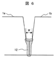
図6及び図7は本発明に係る狭開先レーザ溶接方法を用いて作製した積層溶接ビードの一例を示す断面模式図である。図6は初層溶接ビード形成後を、図7は2層目の溶接ビード形成後の状態を示している。本発明において開先底幅Wとは図6のように、下層溶接ビード(図6では初層溶接ビード12)表面の開先幅方向の開先壁面と下層溶接ビードとの境界間の距離である。また、本発明において溶込み形状の最大幅WMは、図7のように、溶接ビード13の溶込みにおける開先幅方向の最大幅である。溶接ビード13の溶込み高さHは、溶接ビード13の溶込み形状における板厚方向の溶込み下端(最大溶込み部)と溶接ビード表面間の距離である。この溶接ビード13の溶込み高さHは、下層溶接ビードに溶け込んだ深さである溶込み深さPと下層溶接ビード表面から上に盛られた溶接金属の高さ(溶接ビードの積層高さ)Dの和である。
6 and 7 are schematic cross-sectional views showing an example of a laminated weld bead manufactured using the narrow groove laser welding method according to the present invention. FIG. 6 shows the state after forming the first layer weld bead, and FIG. 7 shows the state after forming the second layer weld bead. In the present invention, the groove bottom width W is the distance between the boundary between the groove wall surface in the groove width direction on the surface of the lower layer weld bead (the first
本発明では、2層目以降の溶接ビードの形成の際、上述した溶接ビードの溶け込み高さHと、溶接ビードの開先幅方向の溶込みの最大幅WMとの比H/WMが1.5以上2.5以下となるように溶接条件を制御する。H/WMが1.5未満及び2.5より大きくなると、溶接割れおよび融合不良(溶接金属と被溶接材の非接触部分)が生じやすくなる。 In the present invention, when forming the second and subsequent layers of weld beads, the ratio H / WM of the weld bead penetration height H described above to the maximum weld width WM in the groove width direction of the weld bead is 1. Welding conditions are controlled to be 5 or more and 2.5 or less. When H / WM is less than 1.5 and greater than 2.5, weld cracking and poor fusion (non-contact portion between the weld metal and the welded material) are likely to occur.
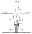
図8は本発明に係る狭開先レーザ溶接方法を用いて作製した積層溶接ビードの一例を示す断面模式図である。図8に示したように、本発明においてレーザ光4の照射幅Sは、開先底面14へ照射されたレーザ光の開先幅方向の幅である。図8の場合は、初層溶接ビード12の表面でのレーザ光の幅(ビーム径)である。
FIG. 8 is a schematic cross-sectional view showing an example of a laminated weld bead produced using the narrow groove laser welding method according to the present invention. As shown in FIG. 8, in the present invention, the irradiation width S of the
本発明では、2層目以降の溶接ビードの形成において、レーザ光4を、照射部におけるレーザ光4の照射幅Sと照射部の開先底幅Wとの比S/Wが1/4以上3/4以下となるように溶接条件を制御する。
In the present invention, in the formation of the second and subsequent weld beads, the ratio S / W between the irradiation width S of the
S/Wが1/4未満の場合、レーザ光が過度に集光され、溶接ビードの幅は狭くなり、深さ方向では深くなりやすく、開先側面の底部に融合不良が生じやすくなる。また、S/Wが3/4を超えると、レーザ光が広い範囲に集光され、溶接ビードの溶け込み高さHが小さくなりやすく、積層された溶接ビード間に融合不良が生じやすくなる。さらに、開先壁とレーザ光が干渉しやすくなるので、ビード形成不良を起こしやすくなり、融合不良や溶接割れを生ずる。 When S / W is less than ¼, the laser beam is excessively condensed, the width of the weld bead is narrowed, and it tends to be deep in the depth direction, and poor fusion tends to occur at the bottom of the groove side surface. On the other hand, if S / W exceeds 3/4, the laser beam is condensed in a wide range, the penetration height H of the weld bead tends to be small, and fusion failure is likely to occur between the stacked weld beads. Furthermore, since the groove wall and the laser beam are likely to interfere with each other, bead formation is liable to occur, resulting in poor fusion and weld cracking.
以上のことから、溶接割れ及び融合不良の無い健全な積層溶接ビードを得るためには、S/Wを1/4以上3/4以下とし、且つ積層ビードの溶込み形状をH/WMが1.5以上2.5以下となるように溶接条件を制御することで、溶接欠陥の発生を抑制することができ、良好な溶接ビードが得られる。 From the above, in order to obtain a sound laminated weld bead free from weld cracks and poor fusion, the S / W is set to 1/4 or more and 3/4 or less, and the penetration shape of the laminated bead is 1 for H / WM. By controlling the welding conditions so as to be 5 or more and 2.5 or less, the occurrence of welding defects can be suppressed, and a good weld bead can be obtained.
なお、レーザ光4の照射幅Sは、レーザ光4の焦点位置15を被溶接材の底面方向又は表面方向(開先板厚方向の上方向)にずらすことにより制御することができる。また、レーザ光4を開先幅方向に揺動・走査させることにより制御することもできる。
The irradiation width S of the
また、溶接ビードの溶込み形状(W、H及びWM)は、レーザ出力、溶接速度、溶接ワイヤ送給速度、レーザ光の照射幅(焦点はずし距離)及び溶接ワイヤ挿入位置等により制御することができる。 Further, the penetration shape (W, H and WM) of the weld bead can be controlled by the laser output, the welding speed, the welding wire feeding speed, the laser beam irradiation width (defocusing distance), the welding wire insertion position, and the like. it can.
Sの値は、集光レンズにおけるレーザ光のビーム径、レンズの焦点距離及びデフォーカス距離によって算出される。また、H、W及びWMの値は、被溶接材の断面を光学顕微鏡により観察して測定することができる。 The value of S is calculated from the beam diameter of the laser light in the condenser lens, the focal length of the lens, and the defocus distance. The values of H, W, and WM can be measured by observing the cross section of the material to be welded with an optical microscope.
本発明の狭開先レーザ溶接方法において、溶接ビードの溶込み深さPを2mm以上7mm以下とすることが好ましい。大型構造物の溶接では、拘束度や構造物の熱容量等の影響で、溶接ビードの溶込み深さPが開先底幅W未満の場合、融合不良を生じやすい。また。溶込み深さが深くなり7mmを超えるようになると溶接割れを生じやすくなる。このため、溶接ビード13の溶込み深さPは、2mm以上7mm以下とすることが好ましい。
In the narrow groove laser welding method of the present invention, the penetration depth P of the weld bead is preferably 2 mm or more and 7 mm or less. In welding of a large structure, if the penetration depth P of the weld bead is less than the groove bottom width W due to the degree of restraint, the heat capacity of the structure, etc., poor fusion tends to occur. Also. When the penetration depth becomes deeper and exceeds 7 mm, weld cracks are likely to occur. For this reason, it is preferable that the penetration depth P of the
図9及び図10は、本発明に係る狭開先レーザ溶接方法を用いて作製した溶接ビードの溶込み形状の一例を示す模式図である。図9は溶込み形状の最大幅WMの位置16が、積層高さDの1/2の位置より上方(被溶接材の表面方向)にある場合の溶込み形状であり、図10は溶込み形状の最大幅WMの位置16が、積層高さDの1/2の位置より下方(被溶接材の底面方向)にある場合の溶込み形状である。溶込み形状の最大幅WMの位置により溶接金属の最終凝固部が異なる。図9のような溶込み形状の場合には、最終凝固部は溶接ビードの表面近傍となる。したがって、仮に溶接ビード形成時に溶接割れが生じても、次の溶接ビード(上層の溶接ビード)の形成時に溶接割れを埋めることができる。また、最上層の溶接ビード形成時に溶接割れが生じても、溶接割れの開口部は表面となるので、溶接割れ有無の判定および補修が容易となるので、溶接検査工程等を大幅に削減することができる。
9 and 10 are schematic views showing an example of a penetration shape of a weld bead produced by using the narrow groove laser welding method according to the present invention. FIG. 9 shows a penetration shape in the case where the
一方、図10のような溶込み形状の場合には、最終凝固部は溶接ビードの中央部分となり、仮に溶接ビード形成時に溶接割れが生じた場合、次の溶接ビード(上層の溶接ビード)の形成時に溶接割れを埋めることができなくなる。また溶接割れ有無の判定を、RTやUTで検査しなければならない。 On the other hand, in the case of the penetration shape as shown in FIG. 10, the final solidified portion becomes the central portion of the weld bead, and if a weld crack occurs during the formation of the weld bead, the next weld bead (upper layer weld bead) is formed. Sometimes it becomes impossible to fill weld cracks. In addition, the determination of the presence or absence of weld cracks must be inspected by RT or UT.
以上のことから、溶接割れおよび融合不良の発生を抑制する積層ビードの溶込み形状としては、開先幅方向の溶込みの最大幅WMの位置16が積層高さDの1/2より上方にある形状とすることが望ましい。
From the above, as the penetration shape of the laminated bead that suppresses the occurrence of weld cracking and poor fusion, the
以下、本発明を実施例によりより具体的に説明するが、本発明は以下の実施例に限定されるものではない。 EXAMPLES Hereinafter, although an Example demonstrates this invention more concretely, this invention is not limited to a following example.
(試験No.1〜15の溶接条件と溶接欠陥評価結果)
本実施例では溶接条件を変えて(開先幅BW、S/W及びH/WMの値を変えて)溶接を行い、溶接欠陥の有無を調査した。
(Test No. 1-15 welding conditions and weld defect evaluation results)
In this example, welding was performed under different welding conditions (with different groove widths BW, S / W, and H / WM), and the presence or absence of welding defects was investigated.
本実施例では、被溶接材1a及び1bとして板厚30mmのオーステナイト系ステンレス鋼SUS316L(Cr当量/Ni当量1.36)用い、溶接ワイヤとしてYS308Lを用いた。ルートフェース10の長さLは、8mmとした。また、開先幅BWを2mm〜4mmとし、開先角度θを4°〜5°とした。
In this example, austenitic stainless steel SUS316L (Cr equivalent / Ni equivalent 1.36) having a plate thickness of 30 mm was used as the materials to be welded 1a and 1b, and YS308L was used as the welding wire. The length L of the
レーザ光として、波長1030nmのレーザ光を使用した。溶接は、レーザ出力:4〜6kW、溶接速度:100〜500mm/min、溶接ワイヤ送給速度:1〜3mm/min、溶接挿入ワイヤ位置:溶接プール中央部として行った。本実施例では、すべての試験について溶接ビードの前開先幅方向の溶込みの幅が最大となる位置が、溶接ビードの積層高さDの1/2より上方となるようにした。初層溶接ビード溶接時のレーザ光の焦点位置を、開先底面の0〜+5mmとした。溶接は下向きおよび横向き姿勢で実施した。Sの値は、0.56〜1mmであり、集光レンズにおけるレーザ光のビーム径、レンズの焦点距離及びデフォーカス距離によって算出した。なお、焦点位置のずらし距離(焦点はずし距離)と照射部におけるレーザ光のビーム径の関係をあらかじめビームプロファイラーを用いて測定し、Sを算出した。本実施例の溶接条件を後述する表1に示す。 A laser beam having a wavelength of 1030 nm was used as the laser beam. Welding was performed as laser output: 4 to 6 kW, welding speed: 100 to 500 mm / min, welding wire feed speed: 1 to 3 mm / min, welding insertion wire position: center of the weld pool. In this example, the position where the penetration width in the pre-groove width direction of the weld bead becomes the maximum for all tests was set to be higher than ½ of the lamination height D of the weld beads. The focal position of the laser beam during the first layer bead welding was set to 0 to +5 mm on the groove bottom surface. Welding was performed in a downward and sideways posture. The value of S was 0.56 to 1 mm, and was calculated from the beam diameter of the laser light in the condenser lens, the focal length of the lens, and the defocus distance. Note that the relationship between the shift distance of the focal position (defocus distance) and the beam diameter of the laser beam in the irradiation unit was measured in advance using a beam profiler, and S was calculated. The welding conditions of this example are shown in Table 1 described later.
なお、開先底幅W、溶接ビードの溶込み深さP及び開先幅方向の溶込みの最大幅WMは、溶接後、構造物から溶接部を切りだし、2層目の溶接ビード断面を光学顕微鏡で観察して測定した値である。 The groove bottom width W, the weld bead penetration depth P, and the maximum weld penetration width WM are cut out from the structure after welding, and the second layer weld bead cross section is obtained. It is the value measured by observing with an optical microscope.
溶接欠陥の評価として、溶接割れの有無及び融合不良の有無を検査した。検査は、溶接後の構造物から溶接部を切りだし、2層目の溶接ビードの断面を光学顕微鏡で観察して溶込み形状から目視で溶接欠陥(溶接割れ及び融合不良)の有無を判断して行った。溶接欠陥が無いものを「合格」とし、溶接割れ及び融合不良の少なくとも1一方があるものを「不合格」と評価した。評価結果を表1に示す。 As evaluation of the welding defect, the presence or absence of weld cracks and the presence or absence of poor fusion were inspected. Inspection is to cut out the weld from the welded structure, observe the cross-section of the second layer weld bead with an optical microscope, and visually determine the presence of weld defects (weld cracks and poor fusion) from the penetration shape. I went. Those having no weld defect were evaluated as “pass”, and those having at least one of weld cracking and poor fusion were evaluated as “fail”. The evaluation results are shown in Table 1.

表1に示したように、本発明の規定(S/Wが1/4以上3/4以下、H/WMが1.5以上2.5以下)を満たすものは、溶接欠陥の評価結果が全て「合格」であったが、本発明の規定を満たさないもの(試験No.2〜4、11、13及び14)は溶接欠陥が生じ、評価結果が「不合格」であった。この結果から、本発明において、溶接欠陥を抑制するためにS/Wが1/4以上3/4以下、H/WMが1.5以上2.5以下とすることが有効であることが示された。 As shown in Table 1, the welding defect evaluation results satisfy the requirements of the present invention (S / W is 1/4 or more and 3/4 or less, H / WM is 1.5 or more and 2.5 or less). Although all were “pass”, those not satisfying the provisions of the present invention (test Nos. 2 to 4, 11, 13, and 14) had weld defects, and the evaluation results were “fail”. From this result, in the present invention, in order to suppress welding defects, it is effective that S / W is ¼ to ¾ and H / WM is 1.5 to 2.5. It was done.
図11は実施例1のS/WとH/WMと溶接欠陥の有無の関係を示す図である。図中、「○」は溶接欠陥無しを示し、「×」は溶接欠陥有りを示す。 FIG. 11 is a diagram illustrating the relationship between S / W, H / WM, and the presence or absence of welding defects in Example 1. In the figure, “◯” indicates that there is no welding defect, and “X” indicates that there is a welding defect.
(試験No.16〜18の溶接条件と評価結果)
本実施例ではレーザ光4の開先幅方向に揺動・走査させる方法により照射幅Sを変えて溶接を行い、溶接欠陥の有無を調査した。レーザ光4の照射幅Sの制御方法以外の条件は、実施例1と同様である。
(Welding conditions and evaluation results of Test Nos. 16 to 18)
In this embodiment, welding was performed by changing the irradiation width S by the method of swinging and scanning the
実施例1では、開先底部に照射されるレーザ光4の照射幅Sは焦点位置を前記狭開先内の照射位置より上方(開先表面方向)にずらすことにより所定の幅になるように制御したが、本実施例では、照射幅Sを、ビームスキャナを用いて開先幅方向に揺動・走査させる方法により制御した。
In the first embodiment, the irradiation width S of the
図12はレーザ光4の揺動幅WEと照射幅Sの関係を示す図である。本実施例では、照射幅Sは開先底面14に照射されたレーザ光4のビーム径LWと揺動幅WEの和とした。図12ではレーザ光4の焦点位置15を開先底面14より上方にずらしているが、焦点位置を開先底面14としてもよい。また、揺動・走査は開先幅方向に往復揺動してもよいが、本実施例では開先中心線を中心とする円状にビームを揺動・走査させた。このため本実施例の照射幅Sは、レーザ光4の円状ビームの直径とレーザビームのスポット径の和とした。レーザ光4のビームの径LWは0.28mm、円状ビームの周波数は8Hz、溶接速度は20cm/minとした。表2に初層溶接後、揺動幅LWを0mm(揺動なし)、1.0mm、1.5mmとして2層目の積層溶接を行った場合の溶込み深さP、S/WおよびH/WMと溶接欠陥の結果を示す。
FIG. 12 is a diagram showing the relationship between the oscillation width WE and the irradiation width S of the
表2に示したように、レーザビームを揺動させてS/Wを本発明の規定範囲内(1/4〜3/4)としたもの(試験No.17及び18)は、溶接欠陥評価結果が全て合格となった。一方、揺動を行わなかった試験No.16は、S/Wが0.09と小さくなり、溶接割れおよび融合不良が認められた。 As shown in Table 2, the laser beam was oscillated and the S / W was within the specified range (1/4 to 3/4) of the present invention (test Nos. 17 and 18). All the results passed. On the other hand, test No. No. 16 had a S / W as small as 0.09, and weld cracking and poor fusion were observed.
以上の結果から、レーザビームを揺動させることで照射幅Sを制御しても、S/Wが1/4〜3/4で、且つH/WMが1.5〜2.5の範囲内であれば健全な溶接ビードが得られることが確認された。なお、本試験では、レーザビームを円状に走査させたが、四角形状、コの字形あるいはU字型に走査させてもよい。 From the above results, even when the irradiation width S is controlled by swinging the laser beam, the S / W is in the range of 1/4 to 3/4 and the H / WM is in the range of 1.5 to 2.5. Then, it was confirmed that a sound weld bead can be obtained. In this test, the laser beam was scanned in a circular shape, but it may be scanned in a square shape, a U shape, or a U shape.
本実施例では、本発明に係る狭開先レーザ溶接方法を用いて、厚板の円筒形構造物を溶接した。図13は本実施例で溶接した開先形状を示す図である。 In this example, a thick cylindrical structure was welded using the narrow groove laser welding method according to the present invention. FIG. 13 is a view showing a groove shape welded in this embodiment.
被溶接材1a及び1bの板厚Lは50mmである。被溶接材1aと1bを突き合わせ、両側に開先溝部11a、11bを形成した。中央部のルートフェース10の高さLは15mmとした。開先幅BWは3mmである。なお、開先溝部11aと11bの開先角度は、収縮、変形等を考慮し、積層進行において各層積層時の開先底幅が3.0±0.3mmの範囲になるように設定した。被溶接材1aと1bと突き合わせはルートフェース10部に合わせ段差17を設けて開先底部がずれないように合わせた。被溶接材1a、1bはCr当量/Ni当量1.40のオーステナイト系ステンレス鋼SUS316Lである。開先底部に照射されるレーザ光4の照射幅Sは焦点位置を前記狭開先内の照射位置より上方(開先表面方向)にずらすことにより所定の幅に設定した。溶接は横向き姿勢で実施した。
The plate thickness L of the materials to be welded 1a and 1b is 50 mm. The welded
図14に本実施例の狭開先レーザ溶接における積層の模式図を示す。図14において、紙面の上方が円筒形構造物の外側であり、紙面の下方が円筒形構造物の内側である。両面から溶接し8パスで接合した。まず初層溶接を両面から行い、初層溶接ビードの12aと12bとをラップさせルートフェース部を完全に溶融させたのち、積層溶接により開先溝部を埋めた。初層後の積層溶接は、まず、外側から2層目溶接ビード18aを形成し、次に内側から溶接して2層目溶接ビード18bを形成した。つぎに内側から溶接し3層目ビード19bを形成したのち、外側から溶接し外側3層目ビード19aを形成した。最終層の4層目は外側4層目ビード20aを形成した後、最後に内側4層目ビード20bを溶接した。表3に各層の溶接前の開先底幅Wとその層の溶込み深さP、レーザビームの照射幅Sと開先底幅Wとの比(S/W)及び溶接ビードの溶込み高さHと開先幅方向の最大溶込み幅WMとの比(H/WM)と、溶接欠陥の評価結果を示す。
FIG. 14 shows a schematic diagram of lamination in the narrow groove laser welding of this example. In FIG. 14, the upper side of the drawing is the outside of the cylindrical structure, and the lower side of the drawing is the inside of the cylindrical structure. Welded from both sides and joined in 8 passes. First layer welding was performed from both sides, and the root face portion was completely melted by lapping the first
いずれの層にも溶接欠陥(溶接割れ及び融合不良)の発生は認められなかった。2層目〜4層目の各ビードの溶込み形状のH/WMは1.6〜2.2であり、溶接割れ並びに融合不良が生じないとされるH/Wの範囲1.5〜2.5内である。また。溶込み深さPも好ましいとされる2mm〜7mmの範囲内である。本実施例の結果、2層目以降の積層溶接においても、S/Wが1/4〜3/4で、且つH/WMが1.5〜2.5の範囲内の溶込み形状が得られる条件で溶接を行えば健全な溶接ビードが得られることが確認された。 The occurrence of weld defects (weld cracks and poor fusion) was not observed in any layer. The H / WM of the penetration shape of each bead of the second layer to the fourth layer is 1.6 to 2.2, and the H / W range of 1.5 to 2 where welding cracks and poor fusion are not caused. .5. Also. The penetration depth P is also preferably in the range of 2 mm to 7 mm. As a result of the present example, a penetration shape in which the S / W is 1/4 to 3/4 and the H / WM is 1.5 to 2.5 is obtained also in the second and subsequent layer welding. It was confirmed that a sound weld bead can be obtained if welding is performed under such conditions.
以上説明したように、本発明によれば溶接割れ及び融合不良を抑制することが可能な狭開先レーザ溶接方法を提供できることが示された。 As described above, according to the present invention, it has been shown that a narrow groove laser welding method capable of suppressing welding cracks and poor fusion can be provided.
なお、上述した実施形態や実施例は、本発明の理解を助けるために説明したものであり、本発明は、記載した具体的な構成のみに限定されるものではない。例えば、ある実施例の構成の一部を他の実施例の構成に置き換えることが可能であり、また、ある実施例の構成に他の実施例の構成を加えることも可能である。すなわち、本発明は、本明細書の実施形態や実施例の構成の一部について、削除・他の構成に置換・他の構成の追加をすることが可能である。 The above-described embodiments and examples have been described for the purpose of facilitating understanding of the present invention, and the present invention is not limited to the specific configurations described. For example, a part of the configuration of one embodiment can be replaced with the configuration of another embodiment, and the configuration of another embodiment can be added to the configuration of one embodiment. That is, according to the present invention, a part of the configurations of the embodiments and examples of the present specification can be deleted, replaced with other configurations, and added with other configurations.
例えば、上記実施例では、30mmと50mm厚さの板の狭開先突き合せ溶接に適用して結果について説明したが、被溶接材はこれらに限定されるものではない。また、本発明の実施例では、Cr当量/Ni当量が1.31〜1.40のオーステナイト系ステンレス鋼を用いたが、Cr当量/Ni当量が1.40以上のオーステナイト系ステンレス鋼SUS304やSUS316L鋼の溶接においても同様な結果が得られるのは言うまでもない。 For example, in the said Example, although applied to the narrow gap butt welding of the board of 30 mm and 50 mm thickness, the result was demonstrated, but a to-be-welded material is not limited to these. In the examples of the present invention, austenitic stainless steel having Cr equivalent / Ni equivalent of 1.31-1.40 was used, but austenitic stainless steel SUS304 or SUS316L having Cr equivalent / Ni equivalent of 1.40 or more. It goes without saying that similar results can be obtained in the welding of steel.
1,1a,1b…被溶接材、2…狭開先、3…溶接ワイヤ、4…レーザ光、5…溶接ビード、6…シールドガスノズル、7…加工ヘッド、8…光ファイバー、9…溶融プール、10…ルートフェース、11…開先溝部、12,12a,12b…初層溶接ビード、13,13a,13b,13c…溶接ビード、14…開先底面、15…レーザ光の焦点位置、16…開先幅方向の溶込みの最大幅WMの位置、17…合わせ段差、18a,18b…2層目溶接ビード、19a,18b…3層目溶接ビード、20a,18b…4層目溶接ビード。
DESCRIPTION OF
Claims (6)
前記狭開先の開先幅は2mm以上4mm以下であり、
2層目以降の前記溶接ビードの形成の際、
前記レーザ光を、前記照射部における前記レーザ光の照射幅Sと前記照射部の開先底幅Wとの比S/Wが1/4以上3/4以下となるように照射し、
且つ、前記溶接ビードの溶込み形状を、前記溶接ビードの積層高さDと下層溶接ビードへの溶込み深さPの和である溶け込み高さHと、前記溶接ビードの開先幅方向の溶込みの最大幅WMとの比H/WMが1.5以上2.5以下となるように溶接条件を制御することを特徴とする狭開先レーザ溶接方法。 The material to be welded is abutted to form a narrow groove, a laser beam is guided into the narrow groove and focused and irradiated, and a welding wire is fed to the laser beam irradiation portion in the narrow groove. in the welding wire and the melt the material to be welded the weld bead formed, narrow groove laser welding method for performing the lamination welding of workpieces the weld bead and multilayer laminate while,
The groove width of the narrow groove is 2 mm or more and 4 mm or less,
When forming the weld bead after the second layer,
Irradiating the laser beam so that a ratio S / W of the irradiation width S of the laser beam and the groove bottom width W of the irradiation unit is 1/4 or more and 3/4 or less,
And the penetration shape of the said weld bead is the penetration height H which is the sum of the lamination | stacking height D of the said weld bead, and the penetration depth P to a lower layer weld bead, and the melt width direction of the said weld bead. A narrow groove laser welding method, wherein a welding condition is controlled so that a ratio H / WM with respect to a maximum width WM is 1.5 to 2.5.
Priority Applications (1)
| Application Number | Priority Date | Filing Date | Title |
|---|---|---|---|
| JP2013266375A JP6155183B2 (en) | 2013-12-25 | 2013-12-25 | Narrow groove laser welding method |
Applications Claiming Priority (1)
| Application Number | Priority Date | Filing Date | Title |
|---|---|---|---|
| JP2013266375A JP6155183B2 (en) | 2013-12-25 | 2013-12-25 | Narrow groove laser welding method |
Publications (3)
| Publication Number | Publication Date |
|---|---|
| JP2015120188A JP2015120188A (en) | 2015-07-02 |
| JP2015120188A5 JP2015120188A5 (en) | 2016-09-01 |
| JP6155183B2 true JP6155183B2 (en) | 2017-06-28 |
Family
ID=53532343
Family Applications (1)
| Application Number | Title | Priority Date | Filing Date |
|---|---|---|---|
| JP2013266375A Active JP6155183B2 (en) | 2013-12-25 | 2013-12-25 | Narrow groove laser welding method |
Country Status (1)
| Country | Link |
|---|---|
| JP (1) | JP6155183B2 (en) |
Families Citing this family (8)
| Publication number | Priority date | Publication date | Assignee | Title |
|---|---|---|---|---|
| JP6470664B2 (en) * | 2015-09-24 | 2019-02-13 | 日立Geニュークリア・エナジー株式会社 | Reactor control rod manufacturing method and reactor control rod |
| CN105397288B (en) * | 2015-12-07 | 2017-04-26 | 中色科技股份有限公司 | Laser welding method for aluminum alloy tailor-welded blanks with equal thicknesses |
| JP6470225B2 (en) * | 2016-04-15 | 2019-02-13 | 株式会社ビアーチェ | Welding method for jewelry or jewelry |
| CN107127453A (en) * | 2017-06-02 | 2017-09-05 | 中国科学院合肥物质科学研究院 | A kind of method for reducing laser filling wire welding austenitic stainless steel fire check |
| CN111299828B (en) * | 2019-11-27 | 2022-02-08 | 北京工业大学 | Thick plate ultra-narrow gap laser wire-filling thermal conduction welding method |
| CN111618434B (en) * | 2020-05-19 | 2021-08-06 | 西安交通大学 | Narrow-gap thick plate wire filling welding method based on laser scanning |
| CN112935549A (en) * | 2021-03-23 | 2021-06-11 | 徐州徐工挖掘机械有限公司 | Narrow-gap laser wire filling welding equipment and method thereof |
| CN114012260A (en) * | 2021-11-19 | 2022-02-08 | 华能国际电力股份有限公司 | Laser welding repair method for crack damage of high-temperature component of gas turbine |
Family Cites Families (5)
| Publication number | Priority date | Publication date | Assignee | Title |
|---|---|---|---|---|
| JPS62220293A (en) * | 1986-03-20 | 1987-09-28 | Mitsubishi Heavy Ind Ltd | Narrow groove laser beam welding method |
| JP2007190586A (en) * | 2006-01-18 | 2007-08-02 | Mitsubishi Heavy Ind Ltd | Welding method, and manufacturing method of liquefied gas tank |
| JP5341538B2 (en) * | 2009-01-30 | 2013-11-13 | 株式会社日立製作所 | Laser welding equipment |
| JP5419807B2 (en) * | 2010-06-16 | 2014-02-19 | 日立Geニュークリア・エナジー株式会社 | Laser welding equipment |
| JP5580788B2 (en) * | 2011-07-12 | 2014-08-27 | 株式会社神戸製鋼所 | Laser welding method for thick steel |
-
2013
- 2013-12-25 JP JP2013266375A patent/JP6155183B2/en active Active
Also Published As
| Publication number | Publication date |
|---|---|
| JP2015120188A (en) | 2015-07-02 |
Similar Documents
| Publication | Publication Date | Title |
|---|---|---|
| JP6155183B2 (en) | Narrow groove laser welding method | |
| JP5827454B2 (en) | Laser / arc combined welding method and welded member manufacturing method using the welding method | |
| Zhang et al. | Welding of thick stainless steel plates up to 50 mm with high brightness lasers | |
| JP5294573B2 (en) | Laser and arc combined welding apparatus and method | |
| JP5260268B2 (en) | Manufacturing method of core shroud for nuclear power plant and nuclear power plant structure | |
| JP6776555B2 (en) | Narrow groove welded joint using laser arc hybrid welding method and its manufacturing method | |
| Pan et al. | Effect of shielding gas on laser–MAG arc hybrid welding results of thick high-tensile-strength steel plates | |
| JP2009262186A (en) | Method of laser welding metal plated plate | |
| KR101831584B1 (en) | Method for laser welding of materials with different thicknesses | |
| Feng et al. | Narrow gap laser welding for potential nuclear pressure vessel manufacture | |
| JP2018075596A (en) | Laser joining method of galvanized steel plate | |
| RU2578303C1 (en) | Method of laser-arc welding of vertical joints of thick-sheet steel structures | |
| JP5866790B2 (en) | Laser welded steel pipe manufacturing method | |
| JP2008168319A (en) | Butt welded joint of steel plate | |
| Vänskä et al. | Laser welding of stainless steel self-steering tube-to-tube joints with oscillating mirror | |
| JP5803160B2 (en) | Laser welded steel pipe manufacturing method | |
| Uemura et al. | Expansion of laser–arc hybrid welding to horizontal and vertical-up welding | |
| WO2017099004A1 (en) | Butt welding method | |
| JP5580788B2 (en) | Laser welding method for thick steel | |
| Spina et al. | T-joints of Ti alloys with hybrid laser-MIG welding: macro-graphic and micro-hardness analyses | |
| Pandey | The effect of tilting angle on penetration depth and profile in laser welding and in submerged arc welding | |
| JP4998634B1 (en) | Laser welding method | |
| JP2006346709A (en) | Laser welding method for thin sheet edge joint | |
| Näsström et al. | Evaluation of a laser-hot-wire hybrid process for producing deep net-shape welds | |
| Vänskä et al. | Orbital cutting and welding of stainless steel tubes with a fiber laser |
Legal Events
| Date | Code | Title | Description |
|---|---|---|---|
| A521 | Written amendment |
Free format text: JAPANESE INTERMEDIATE CODE: A523 Effective date: 20160715 |
|
| A621 | Written request for application examination |
Free format text: JAPANESE INTERMEDIATE CODE: A621 Effective date: 20160715 |
|
| A977 | Report on retrieval |
Free format text: JAPANESE INTERMEDIATE CODE: A971007 Effective date: 20170512 |
|
| TRDD | Decision of grant or rejection written | ||
| A01 | Written decision to grant a patent or to grant a registration (utility model) |
Free format text: JAPANESE INTERMEDIATE CODE: A01 Effective date: 20170523 |
|
| A61 | First payment of annual fees (during grant procedure) |
Free format text: JAPANESE INTERMEDIATE CODE: A61 Effective date: 20170605 |
|
| R150 | Certificate of patent or registration of utility model |
Ref document number: 6155183 Country of ref document: JP Free format text: JAPANESE INTERMEDIATE CODE: R150 |