JP6152516B2 - System and method for targeting cardiac rhythm disorders using shaped ablation - Google Patents
System and method for targeting cardiac rhythm disorders using shaped ablation Download PDFInfo
- Publication number
- JP6152516B2 JP6152516B2 JP2014509410A JP2014509410A JP6152516B2 JP 6152516 B2 JP6152516 B2 JP 6152516B2 JP 2014509410 A JP2014509410 A JP 2014509410A JP 2014509410 A JP2014509410 A JP 2014509410A JP 6152516 B2 JP6152516 B2 JP 6152516B2
- Authority
- JP
- Japan
- Prior art keywords
- shape
- heart
- activation
- source
- signal
- Prior art date
- Legal status (The legal status is an assumption and is not a legal conclusion. Google has not performed a legal analysis and makes no representation as to the accuracy of the status listed.)
- Expired - Fee Related
Links
Images


Classifications
-
- A—HUMAN NECESSITIES
- A61—MEDICAL OR VETERINARY SCIENCE; HYGIENE
- A61B—DIAGNOSIS; SURGERY; IDENTIFICATION
- A61B5/00—Measuring for diagnostic purposes; Identification of persons
- A61B5/24—Detecting, measuring or recording bioelectric or biomagnetic signals of the body or parts thereof
- A61B5/25—Bioelectric electrodes therefor
- A61B5/279—Bioelectric electrodes therefor specially adapted for particular uses
- A61B5/28—Bioelectric electrodes therefor specially adapted for particular uses for electrocardiography [ECG]
- A61B5/283—Invasive
-
- G—PHYSICS
- G06—COMPUTING; CALCULATING OR COUNTING
- G06F—ELECTRIC DIGITAL DATA PROCESSING
- G06F18/00—Pattern recognition
-
- A—HUMAN NECESSITIES
- A61—MEDICAL OR VETERINARY SCIENCE; HYGIENE
- A61B—DIAGNOSIS; SURGERY; IDENTIFICATION
- A61B18/00—Surgical instruments, devices or methods for transferring non-mechanical forms of energy to or from the body
- A61B18/04—Surgical instruments, devices or methods for transferring non-mechanical forms of energy to or from the body by heating
- A61B18/12—Surgical instruments, devices or methods for transferring non-mechanical forms of energy to or from the body by heating by passing a current through the tissue to be heated, e.g. high-frequency current
- A61B18/14—Probes or electrodes therefor
- A61B18/1492—Probes or electrodes therefor having a flexible, catheter-like structure, e.g. for heart ablation
-
- A—HUMAN NECESSITIES
- A61—MEDICAL OR VETERINARY SCIENCE; HYGIENE
- A61B—DIAGNOSIS; SURGERY; IDENTIFICATION
- A61B5/00—Measuring for diagnostic purposes; Identification of persons
- A61B5/02—Detecting, measuring or recording pulse, heart rate, blood pressure or blood flow; Combined pulse/heart-rate/blood pressure determination; Evaluating a cardiovascular condition not otherwise provided for, e.g. using combinations of techniques provided for in this group with electrocardiography or electroauscultation; Heart catheters for measuring blood pressure
-
- A—HUMAN NECESSITIES
- A61—MEDICAL OR VETERINARY SCIENCE; HYGIENE
- A61B—DIAGNOSIS; SURGERY; IDENTIFICATION
- A61B5/00—Measuring for diagnostic purposes; Identification of persons
- A61B5/24—Detecting, measuring or recording bioelectric or biomagnetic signals of the body or parts thereof
- A61B5/316—Modalities, i.e. specific diagnostic methods
- A61B5/318—Heart-related electrical modalities, e.g. electrocardiography [ECG]
- A61B5/346—Analysis of electrocardiograms
- A61B5/349—Detecting specific parameters of the electrocardiograph cycle
- A61B5/361—Detecting fibrillation
-
- A—HUMAN NECESSITIES
- A61—MEDICAL OR VETERINARY SCIENCE; HYGIENE
- A61B—DIAGNOSIS; SURGERY; IDENTIFICATION
- A61B5/00—Measuring for diagnostic purposes; Identification of persons
- A61B5/24—Detecting, measuring or recording bioelectric or biomagnetic signals of the body or parts thereof
- A61B5/316—Modalities, i.e. specific diagnostic methods
- A61B5/318—Heart-related electrical modalities, e.g. electrocardiography [ECG]
- A61B5/346—Analysis of electrocardiograms
- A61B5/349—Detecting specific parameters of the electrocardiograph cycle
- A61B5/363—Detecting tachycardia or bradycardia
-
- A—HUMAN NECESSITIES
- A61—MEDICAL OR VETERINARY SCIENCE; HYGIENE
- A61B—DIAGNOSIS; SURGERY; IDENTIFICATION
- A61B5/00—Measuring for diagnostic purposes; Identification of persons
- A61B5/40—Detecting, measuring or recording for evaluating the nervous system
- A61B5/4029—Detecting, measuring or recording for evaluating the nervous system for evaluating the peripheral nervous systems
-
- A—HUMAN NECESSITIES
- A61—MEDICAL OR VETERINARY SCIENCE; HYGIENE
- A61B—DIAGNOSIS; SURGERY; IDENTIFICATION
- A61B5/00—Measuring for diagnostic purposes; Identification of persons
- A61B5/40—Detecting, measuring or recording for evaluating the nervous system
- A61B5/4058—Detecting, measuring or recording for evaluating the nervous system for evaluating the central nervous system
- A61B5/4064—Evaluating the brain
-
- A—HUMAN NECESSITIES
- A61—MEDICAL OR VETERINARY SCIENCE; HYGIENE
- A61B—DIAGNOSIS; SURGERY; IDENTIFICATION
- A61B5/00—Measuring for diagnostic purposes; Identification of persons
- A61B5/48—Other medical applications
- A61B5/4836—Diagnosis combined with treatment in closed-loop systems or methods
- A61B5/4839—Diagnosis combined with treatment in closed-loop systems or methods combined with drug delivery
-
- A—HUMAN NECESSITIES
- A61—MEDICAL OR VETERINARY SCIENCE; HYGIENE
- A61M—DEVICES FOR INTRODUCING MEDIA INTO, OR ONTO, THE BODY; DEVICES FOR TRANSDUCING BODY MEDIA OR FOR TAKING MEDIA FROM THE BODY; DEVICES FOR PRODUCING OR ENDING SLEEP OR STUPOR
- A61M5/00—Devices for bringing media into the body in a subcutaneous, intra-vascular or intramuscular way; Accessories therefor, e.g. filling or cleaning devices, arm-rests
-
- A—HUMAN NECESSITIES
- A61—MEDICAL OR VETERINARY SCIENCE; HYGIENE
- A61N—ELECTROTHERAPY; MAGNETOTHERAPY; RADIATION THERAPY; ULTRASOUND THERAPY
- A61N1/00—Electrotherapy; Circuits therefor
- A61N1/02—Details
- A61N1/04—Electrodes
- A61N1/05—Electrodes for implantation or insertion into the body, e.g. heart electrode
- A61N1/056—Transvascular endocardial electrode systems
- A61N1/0565—Electrode heads
-
- A—HUMAN NECESSITIES
- A61—MEDICAL OR VETERINARY SCIENCE; HYGIENE
- A61B—DIAGNOSIS; SURGERY; IDENTIFICATION
- A61B18/00—Surgical instruments, devices or methods for transferring non-mechanical forms of energy to or from the body
- A61B2018/00315—Surgical instruments, devices or methods for transferring non-mechanical forms of energy to or from the body for treatment of particular body parts
- A61B2018/00345—Vascular system
- A61B2018/00351—Heart
- A61B2018/00357—Endocardium
-
- A—HUMAN NECESSITIES
- A61—MEDICAL OR VETERINARY SCIENCE; HYGIENE
- A61B—DIAGNOSIS; SURGERY; IDENTIFICATION
- A61B18/00—Surgical instruments, devices or methods for transferring non-mechanical forms of energy to or from the body
- A61B2018/00571—Surgical instruments, devices or methods for transferring non-mechanical forms of energy to or from the body for achieving a particular surgical effect
- A61B2018/00577—Ablation
-
- A—HUMAN NECESSITIES
- A61—MEDICAL OR VETERINARY SCIENCE; HYGIENE
- A61B—DIAGNOSIS; SURGERY; IDENTIFICATION
- A61B18/00—Surgical instruments, devices or methods for transferring non-mechanical forms of energy to or from the body
- A61B2018/00636—Sensing and controlling the application of energy
- A61B2018/00773—Sensed parameters
- A61B2018/00839—Bioelectrical parameters, e.g. ECG, EEG
Description
政府権利
本出願で述べる研究のいくつかは、アメリカ国立衛生研究所(National Institutes of Health)との契約R01 HL83359、HL83359−S1、およびHL103800により、資金援助を受けた。したがって、米国政府は、本発明に特定の権利を有する。
Government Rights Some of the studies described in this application were funded by contracts R01 HL83359, HL83359-S1, and HL103800 with the National Institutes of Health. Accordingly, the US government has certain rights in the invention.
関連出願の相互参照
本出願は、2011年5月2日出願の米国仮特許出願第61/481,512号明細書の利益を主張するものであり、この開示はその全体が参照により本明細書に組み込まれる。
This application claims the benefit of US Provisional Patent Application No. 61 / 481,512, filed May 2, 2011, the disclosure of which is hereby incorporated by reference in its entirety. Incorporated into.
本発明は、一般に医療の分野に関し、より詳細には、成形アブレーションを使用して生物学的律動の律動不整および他の律動障害を標的とするためのシステムおよび方法に関する。特に、本発明は、生物学的律動障害を検出、診断、および治療するために、最小侵襲性技法または外科的技法に適用することができる。いくつかの実施形態は、心律動の障害を対象としており、他の実施形態は、脳および神経系の電気的な障害を対象としており、さらに他の実施形態は、胃腸管および泌尿生殖器系の平滑筋の電気的または収縮障害を対象としている。 The present invention relates generally to the field of medicine, and more particularly to a system and method for targeting rhythm irregularities in biological rhythms and other rhythm disorders using shaped ablation. In particular, the present invention can be applied to minimally invasive or surgical techniques to detect, diagnose, and treat biological rhythm disorders. Some embodiments are directed to disorders of the heart rhythm, other embodiments are directed to electrical disorders of the brain and nervous system, and still other embodiments are of the gastrointestinal tract and urogenital system. Intended for smooth muscle electrical or contractile disorders.
心律動障害は、米国では非常に一般的であり、病的状態、就業不能、および死の重大な原因である。心律動障害は多くの形態で生じ、そのうち最も複雑で治療が難しいのは、心房細動(AF)、心室頻拍(VT)、および心室細動(VF)である。他の律動は、より治療が単純であるが、やはり臨床的に重要であることがあり、そのような律動としては、心房頻脈(AT)、上室頻拍(SVT)、心房粗動(AFL)、心房性期外収縮/拍動(SVE)、および心室性期外収縮/拍動(PVC)が挙げられる。いくつかの特定の条件下では、正常な洞房結節の急速な活性化が、不適切洞性頻拍または洞房結節リエントリといった心律動障害を引き起こすことがある。 Heart rhythm disorders are very common in the United States and are a significant cause of morbidity, inability to work, and death. Heart rhythm disorders occur in many forms, the most complex and difficult to treat are atrial fibrillation (AF), ventricular tachycardia (VT), and ventricular fibrillation (VF). Other rhythms are simpler to treat, but may still be clinically important, such as atrial tachycardia (AT), supraventricular tachycardia (SVT), atrial flutter ( AFL), atrial premature contraction / beat (SVE), and ventricular premature contraction / beat (PVC). Under some specific conditions, rapid activation of normal sinoatrial node may cause cardiac rhythm disturbances such as inappropriate sinus tachycardia or sinoatrial node reentry.
心律動障害、特にAF、VF、およびVTといった複雑な律動障害の治療は非常に難しいことがある。薬理療法は、特に、AFには最適でなく(Singh,Singh et al.2005)、VTまたはVFにも最適でなく(Bardy,Lee et al.2005)、その結果、非薬理療法に大きな関心が向けられている。アブレーションは、心律動障害を解消するために有望であり、使用が増えている療法であり、これは、血管を通して、または手術で直接、センサ/プローブを心臓に導き、次いで心律動障害の原因にエネルギーを送達して心律動障害を収束させることによって行われる。アブレーションは、当初はSVT、AFL、PVC、PACなど「単純な」障害に使用されていたが、AFの治療に対する使用(Cappato,Calkins et al.2005)、VTの治療に対する使用(Reddy,Reynolds et al.2007)、さらには、より少ないものの、VFの治療に対する使用(Knecht,Sacher et al.2009)も増えている。 Treatment of cardiac rhythm disorders, particularly complex rhythm disorders such as AF, VF, and VT, can be very difficult. Pharmacotherapeutics are not particularly optimal for AF (Singh, Singh et al. 2005), and not optimal for VT or VF (Bardy, Lee et al. 2005), resulting in great interest in non-pharmacological therapies. Is directed. Ablation is a promising and increasingly used therapy for relieving heart rhythm disturbances, which leads the sensor / probe to the heart, either through blood vessels or directly in surgery, and then causes heart rhythm disorders It is done by delivering energy and converging heart rhythm disorders. Ablation was initially used for “simple” disorders such as SVT, AFL, PVC, and PAC, but was used for the treatment of AF (Cappato, Calkins et al. 2005), for the treatment of VT (Reddy, Reynolds et al. al. 2007) and, to a lesser extent, use for the treatment of VF (Knecht, Sacher et al. 2009) is also increasing.
アブレーション療法は、単純な心律動障害および複雑な心律動障害を治療するためにますます多く適用されている。しかし、アブレーションが適用される様式は、活性化が拍動ごとに変化しない単純な心律動障害から導出されて適合されたものであり、拍動ごとに活性化が変化する複雑な心律動障害の治療における重大な相違点の明確な理解を伴っていない。 Ablation therapy is increasingly being applied to treat simple and complex cardiac rhythm disorders. However, the manner in which ablation is applied is derived and adapted from simple cardiac rhythm disorders in which activation does not change from beat to beat, and is a complex heart rhythm disorder in which activation changes from beat to beat. There is no clear understanding of the significant differences in treatment.
特に、ほぼすべてのアブレーション療法は、単一点アブレーション(または「外傷」)として、またはそのような外傷の組合せとして心臓組織に送達され、これは、(しばしばそのような「点領域」の連続するクラスタによって)心臓の非伝導領域をつなぐために連続的なリエントリ回路を二分する目的を有する。これは、心房頻拍、肺静脈頻拍、限局性の心室頻拍、房室結節リエントリ、および副伝導路を必要とする房室リエントリなどの単純な律動が、心臓の小さな点領域での特定の異常に関わるという概念に基づく。位置を識別した後、アブレーションが、これらの点領域に適用される。典型的および非典型的な心房粗動によって例示される他の単純な律動は、「峡部(isthmus)」と呼ばれる組織の特殊な領域を通る電気活性化の経路に関わる。そこで、アブレーションは、峡部を遮断または二分するように設計された連続する一連の点(しばしばアブレーション「ライン」と呼ばれる)によって実現されるが、そのようなアブレーションラインは、外科的に検査した場合に直線でないことが多い(Cox,Heart Rhythm 2005)。 In particular, almost all ablation therapies are delivered to the heart tissue as single point ablation (or “trauma”) or as a combination of such trauma, which is often a continuous cluster of such “point regions”. With the purpose of bisecting a continuous reentry circuit to connect non-conducting regions of the heart. This is because simple rhythms such as atrial tachycardia, pulmonary venous tachycardia, focal ventricular tachycardia, atrioventricular nodal reentry, and atrioventricular reentry requiring a secondary conduction pathway are Based on the concept of involving specific anomalies. After identifying the location, ablation is applied to these point areas. Another simple rhythm illustrated by typical and atypical atrial flutter involves a pathway of electrical activation through a special region of tissue called the “isthmus”. Thus, ablation is achieved by a series of consecutive points (often called ablation “lines”) designed to block or bisect the isthmus, but such ablation lines can be Often not straight (Cox, Heart Rhythm 2005).
しかし、心房細動、多形性心室頻拍、または心室細動など、活性化経路が拍動ごとに変化することがある複雑な律動障害に関するアブレーション療法は、はるかに難しい。これは、一部には、心律動障害の原因を識別して位置特定するためのツールが優れておらず、障害を収束させて解消するために適切な領域にエネルギーを送達する試みを妨げているためである。広く見られるAFの一形態である持続性AFでは、アブレーションは、4〜5時間の長い処置にもかかわらず、1回の処置の成功率がわずか50〜60%であり(Cheema,Vasamreddy et al.2006;Calkins,Brugada et al.2007)、死亡例(Cappato,Calkins et al.2009)を含めた重大な合併症の率が5〜10%である(Ellis,Culler et al.2009)。 However, ablation therapy for complex rhythm disorders where the activation pathway can change from beat to beat, such as atrial fibrillation, polymorphic ventricular tachycardia, or ventricular fibrillation, is much more difficult. This, in part, hinders attempts to deliver energy to the appropriate area to converge and resolve the disorder, as tools for identifying and locating the cause of cardiac rhythm disorders are not good. Because it is. In persistent AF, a common form of AF, ablation is only 50-60% successful in one treatment despite long treatments of 4-5 hours (Cheema, Vasamreddy et al 2006; Calkins, Brugada et al. 2007), and the rate of serious complications including death (Cappato, Calkins et al. 2009) is 5-10% (Ellis, Culler et al. 2009).
心房頻拍など「単純な」障害に関しても、アブレーション療法のサイズおよび形状を正確に識別するためのツールは存在しない。これは、電気活性化が点源から心臓内に同心では広がらないので、特に重要である。洞房結節など正常な構造からの縦方向と横方向の伝導の差は、正常な組織でさえよく見られ(Fedorov,2009 #5273;Fedorov,2010 #5738)、心房頻拍を持続させる異常な組織ではより大きいことがある(Higa,2004 #1686)。それにもかかわらず、これらの律動のアブレーションのための手法は、点のクラスタリングまたはアブレーション「ライン」に関わる。 Even for “simple” disorders such as atrial tachycardia, there is no tool to accurately identify the size and shape of ablation therapy. This is particularly important because electrical activation does not spread concentrically from the point source into the heart. Differences in longitudinal and lateral conduction from normal structures such as sinoatrial nodes are common even in normal tissues (Fedorov, 2009 # 5273; Fedorov, 2010 # 5738) and abnormal tissues that sustain atrial tachycardia. May be larger (Higa, 2004 # 1686). Nevertheless, these rhythm ablation approaches involve point clustering or ablation “lines”.
心房細動(AF)、多形性心室頻拍、または進行中の心室細動などの複雑な律動を解消するためのアブレーション療法のサイズおよび形状に関しては、さらによく分かっていない。AFのアブレーションは、多くの患者において、アブレーションが典型的には心房表面の50%超を破壊する(Cox,Heart Rhythm 2005)が、それでも、1回の処置での治癒率は1年後に50〜60%である(Calkins,Heart Rhythm 2012;Weerasooriya,J Am Coll Cardiol.2011)という厳しい実例を提供する。この食い違いは、AFに関する根源を識別するのが極端に難しいことによる。したがって、AFを治療するためのアブレーションの適正なサイズおよび形状は、本質的には分かっていない。律動障害に対する関連性の明らかな証拠がないまま心臓組織のかなりの部分をアブレーションすることは、AFアブレーションによる悪影響のリスクを5〜10%生じることがあり(Dixit,Heart Rhythm 2007;Ellis,Heart Rhythm 2009)、そのようなリスクには、心臓から食道への穿孔による死、肺静脈の狭まり(狭窄)、横隔神経への損傷が含まれ、近年述べられているアブレーションによる極度の心房破壊時の左心房硬直症候群(stiff left atrial syndrome)は、非拡張性心室(non−distensible chamber)を生じ、これは、前に健康であったAF患者においてさえ心不全を引き起こす(Gibson,Heart Rhythm 2011)。 Even less is known about the size and shape of ablation therapies to resolve complex rhythms such as atrial fibrillation (AF), polymorphic ventricular tachycardia, or ongoing ventricular fibrillation. Although AF ablation typically destroys more than 50% of the atrial surface in many patients (Cox, Heart Rhythm 2005), the cure rate for a single procedure is still 50- It provides a strict example of 60% (Calkins, Heart Rhythm 2012; Weerasooriya, Jam Coll Cardiol. 2011). This discrepancy is due to the extreme difficulty in identifying the source for AF. Thus, the proper size and shape of ablation to treat AF is essentially unknown. Ablating a significant portion of heart tissue without clear evidence of a link to rhythm disturbances can create a 5-10% risk of adverse effects from AF ablation (Dixit, Heart Rhythm 2007; Ellis, Heart Rhythm). 2009), such risks include death from perforation of the heart to the esophagus, narrowing of the pulmonary veins (stenosis), damage to the phrenic nerve, and during severe atrial destruction due to ablation described in recent years Left aft rigid syndrome results in a non-distensible chamber that causes heart failure even in previously healthy AF patients (Gibson, Heart Rhythm 2) 11).
アブレーション療法のために使用される多くのカテーテルシステムは、管状/シャフトカテーテル端部の先端からの点として、外傷を送達する。アブレーションラインは、隣接する位置にカテーテル先端を移動させることによって実現されるが、これは、律動障害の根源に関しては経験的である。様々な形状をアブレーションするために、Ablation FrontiersによるPVAC、TVAC、またはMACカテーテルなど、より新しいシステムが設計されているが(Scharf,2009)、これらの形状も経験的である(TVACのライン形状、またはMACの星形)か、または解剖学的領域に適合するように設計される(PVACに関する肺静脈口など)。心臓組織内の律動障害の実際の根源の形状にアブレーション療法を適合させるように設計されたカテーテルシステムはない。なぜなら、そのような根源形状は、特に複雑な心律動障害に関しては、現在議論、研究、または定義されていないからである。 Many catheter systems used for ablation therapy deliver trauma as a point from the tip of the tubular / shaft catheter end. The ablation line is achieved by moving the catheter tip to an adjacent position, which is empirical with respect to the source of rhythm disturbances. Newer systems such as PVAC, TVAC, or MAC catheters by Ablation Fronters have been designed to ablate various shapes (Scharf, 2009), but these shapes are also empirical (TVAC line shapes, Or MAC star) or designed to fit an anatomical region (such as the pulmonary vein port for PVAC). There is no catheter system designed to adapt ablation therapy to the shape of the actual source of rhythm disturbances in the heart tissue. This is because such source shapes are not currently discussed, studied, or defined, particularly with respect to complex cardiac rhythm disorders.
アブレーションに関する心律動障害の正確な根源を識別する際の難点は、最も洗練された既知のシステムが、術者が解釈しなければならないデータを表示するが、術者が障害の原因を検出、診断、および治療することができるように障害の原因を直接識別および位置特定することはないことに依存する。これは、Beattyと共同研究者らによる米国特許第5,662,108号明細書、米国特許第5,662,108号明細書、米国特許第6,978,168号明細書、米国特許第7,289,843、および他の特許、HauckおよびSchultzによる米国特許第7,263,397号明細書、Tarjanと共同研究者らによる米国特許第7,043,292号明細書、Ben−Haimと共同研究者らによる米国特許第6,892,091号明細書および他の特許、ならびにXueと共同研究者らによる米国特許第6,920,350号明細書に記載されている現在使用されている方法を含む。これらの方法および機器は、しばしば洗練された3次元の解剖学的表現で電位を検出、解析、および表示するが、特にAFなど複雑な障害に関しては、心律動障害の原因を識別して位置特定することは依然としてできない。これはまた、心臓に電位を「投影(project)」するために身体表面からの信号を使用するRudyと共同研究者らによる特許(とりわけ米国特許第6,975,900号明細書および米国特許第7,016,719号明細書)にも当てはまる。 The difficulty in identifying the exact source of heart rhythm disorders related to ablation is that the most sophisticated and well-known system displays the data that the surgeon must interpret, but the surgeon detects and diagnoses the cause of the disorder , And not relying directly on identifying and locating the cause of the disorder so that it can be treated. This is described in US Pat. No. 5,662,108, US Pat. No. 5,662,108, US Pat. No. 6,978,168, US Pat. , 289,843, and other patents, US Pat. No. 7,263,397 by Hauck and Schultz, US Pat. No. 7,043,292 by Tarjan and co-workers, in collaboration with Ben-Haim Currently used methods described in US Pat. No. 6,892,091 and other patents by researchers, and US Pat. No. 6,920,350 by Xue and co-workers including. These methods and instruments often detect, analyze, and display potentials in sophisticated three-dimensional anatomical representations, but identify and locate the cause of cardiac rhythm disorders, especially for complex disorders such as AF. I still can't do it. This also includes patents by Rudy and co-workers (especially US Pat. No. 6,975,900 and US Pat. 7,016,719).
心律動障害の原因を識別して位置特定するためのいくつかの既知の方法は、単純な律動障害には有効であることがあるが、AF、VF、または多形性VTなど複雑な障害の原因の識別に関して成功している既知の方法はない。さらに、関連のない(正常な)心臓組織の損傷を最小限にしながら心律動障害を解消するために、アブレーション療法のサイズおよび形状を識別する技法は現在ない。活性化マッピング(活性化を最も早発の部位まで遡らせる)は、頻拍など単純な心律動障害にしか有用でなく、AFL(明確な「開始」がない連続的な律動)にはあまり有効でなく、変化する活性化経路を伴うAFには全く有効でない。エントレインメントマッピング(entrainment mapping)は、律動の原因に刺激電極が位置する部位を識別するためにペーシングを使用するが、ペーシングは、自動メカニズムにより、AF、さらには心房頻拍などいくつかの「単純な」律動にさえ適用することができない。房室結節リエントリ、典型的なAFL、および早期(発作性)AFを起こしている患者の原因に関しては典型的な位置(stereotypical locations)が分かっていないが、持続性AF(Calkins,Brugada et al.2007)、VF、および他の複雑な障害を患う大半の患者に関しては分かっていない。したがって、律動障害に関連しない周囲組織の損傷を最小限にしながらアブレーションを行うために、AF(Calkins,Brugada et al.2007)など複雑な心律動障害の根源の位置、サイズ、および形状を正確に識別するための方法はまだ存在しない。 Some known methods for identifying and locating the cause of cardiac rhythm disorders may be effective for simple rhythm disorders, but for complex disorders such as AF, VF, or polymorphic VT There is no known method that has succeeded in identifying the cause. Furthermore, there are currently no techniques for identifying the size and shape of ablation therapies to eliminate cardiac rhythm disturbances while minimizing unrelated (normal) cardiac tissue damage. Activation mapping (returning activation to the earliest site) is only useful for simple cardiac rhythm disorders such as tachycardia, and is less effective for AFL (continuous rhythm without a clear "onset") But not at all for AF with varying activation pathways. Entrainment mapping uses pacing to identify the site where the stimulation electrode is located at the cause of the rhythm, but pacing is automated by some “simple” mechanisms such as AF and even atrial tachycardia. It can't be applied even to the rhythm. Although the stereotypical locations are unknown for the causes of patients with atrioventricular nodal reentry, typical AFL, and early (paroxysmal) AF, persistent AF (Calcins, Brugada et al 2007), the majority of patients suffering from VF and other complex disorders are unknown. Therefore, the location, size, and shape of the source of complex cardiac rhythm disorders such as AF (Calkins, Brugada et al. 2007) must be accurately determined to perform ablation while minimizing damage to surrounding tissue not related to rhythm disorders. There is still no way to identify it.
拍動ごとに一貫した活性化を有する「単純な」律動に関するシステムの一例は、SvensonおよびKingによる米国特許第5,172,699号明細書によって与えられている。このシステムは、心拡張インターバルの所見に基づき、心拡張インターバルは、「単純な律動」では定義することができるが、心房細動(AF)や心室細動(VF)など複雑な律動では定義することができない(Calkins,Brugada et al.2007;Waldo and Feld 2008)。さらに、このシステムは、活性化自体ではなく(活性化の間の)心拡張インターバルを検査するので、原因を識別または位置特定しない。さらに、ECGでのQRS群間の時間間隔を分析するので、AFまたはVFではなく心室頻拍に焦点を当てられる。 An example of a system for a “simple” rhythm with consistent activation from beat to beat is given by US Pat. No. 5,172,699 by Svenson and King. This system is based on the findings of diastole intervals, which can be defined by “simple rhythms” but by complex rhythms such as atrial fibrillation (AF) and ventricular fibrillation (VF). (Calkins, Brugada et al. 2007; Waldo and Feld 2008). In addition, the system does not identify or locate the cause because it examines the diastole interval (during activation) rather than the activation itself. In addition, since the time interval between QRS groups in the ECG is analyzed, the focus is on ventricular tachycardia rather than AF or VF.
別の例は、CiaccioおよびWitによる米国特許第6,236,883号明細書である。このシステムは、リエントリ性の回路を識別して局所化するために電極の同心アレイを使用する。したがって、これは、限局性拍動などリエントリ性でない原因は所見しない。さらに、特徴および検出局所化アルゴリズムを使用する方法は、心臓内の活性化が拍動ごとに変化するAFやVFなど複雑な律動には有効でない。この方法は、「リエントリ回路の峡部内でのゆっくりとした伝達」を識別し、これは、心室頻拍など「単純な」不整脈の特徴であるが、AFおよびVFに関しては定義されない。さらに、峡部のサイズおよび形状は定義されておらず、したがって、アブレーションは、点、点の無定形のクラスタ(アブレーションを停止する終点が不明確である)、または「ライン」に経験的に向けられる。 Another example is US Pat. No. 6,236,883 by Ciaccio and Wit. This system uses a concentric array of electrodes to identify and localize reentrant circuits. Therefore, this does not find any cause that is not reentrant, such as localized pulsation. Furthermore, methods using feature and detection localization algorithms are not effective for complex rhythms such as AF and VF where activation in the heart changes with each beat. This method identifies “slow transmission within the canyon of the reentry circuit”, which is a characteristic of “simple” arrhythmias such as ventricular tachycardia, but is not defined for AF and VF. In addition, the size and shape of the isthmus are not defined, so ablation is empirically directed to a point, an amorphous cluster of points (the end point at which ablation stops is unclear), or “line” .
米国特許第6,847,839号明細書において、Ciaccioと共同研究者らは、正常な(正弦波の)律動でのリエントリ回路を識別および局所化するための発明を述べている。やはりこれも、活性化が半径方向に発散する、リエントリ性ではなく限局性の不整脈に関する原因を所見しない。第2に、この特許は、リエントリに関する「峡部」の洞律動の存在に基づき、これは、VTなど拍動間で一貫した活性化を有する「単純な」律動に関しては許容される((Reddy,Reynolds et al.2007)参照)。しかし、これは、AFやVFなど変化する活性化経路を有する複雑な律動には許容されない。 In US Pat. No. 6,847,839, Ciaccio and co-workers describe an invention for identifying and localizing reentry circuits with normal (sinusoidal) rhythms. Again, this does not reveal a cause for focal arrhythmias rather than reentry, where activation diverges in the radial direction. Second, the patent is based on the existence of a “gorge” sinus rhythm with respect to reentry, which is acceptable for “simple” rhythms with consistent activation between beats such as VT ((Reddy , Reynolds et al. 2007)). However, this is not allowed for complex rhythms with varying activation pathways such as AF and VF.
Desaiによる米国特許第6,522,905号明細書は、最も早い活性化部位を見つけ出し、これを不整脈の原因であると判断する原理を使用する。この手法は、リエントリによる単純な不整脈には有効でない。単純な不整脈では、活性化が連続的な「円」であるので、リエントリでの「最も早い」部位は存在しない。また、この手法は、AFやVFなど拍動ごとに活性化が変化する複雑な不整脈にも有効でない。 US Pat. No. 6,522,905 to Desai uses the principle of finding the earliest activation site and determining that it is the cause of arrhythmia. This approach is not effective for simple arrhythmias due to reentry. In simple arrhythmias, activation is a continuous “circle”, so there is no “earliest” site for reentry. This method is also not effective for complicated arrhythmias such as AF and VF whose activation changes with each beat.
しかし、単純な心律動障害においてさえ、既知の方法を適用して原因を識別するのは難しいことが多い。例えば、心房頻拍(「単純な」障害)のためのアブレーション治療の成功は、70%と低いことがある。外科医が心律動障害手術を行うとき(Cox2004;Abreu Filho,2005)、外科医は、心律動障害の専門家(心臓電気生理学者)によって補佐されるのが理想的である。すなわち、心律動障害の原因をアブレートすることは難題であることがあり、熟練した術者でさえ、心房頻拍や異型の(左心房)AFLなど、(拍動間の活性化パターンが一貫している)特定の「単純な」律動障害をアブレートするのに数時間かかることがある。活性化シーケンスが拍動ごとに変化するAFやVFなど複雑な心律動障害に関しては、状況はさらに難しくなる。 However, even in simple heart rhythm disorders, it is often difficult to identify causes by applying known methods. For example, the success of ablation treatment for atrial tachycardia (a “simple” disorder) can be as low as 70%. When a surgeon performs a cardiac rhythm disorder operation (Cox 2004; Abreu Filho, 2005), the surgeon is ideally assisted by a cardiac rhythm disorder specialist (cardiac electrophysiologist). In other words, ablating the cause of heart rhythm disturbances can be a challenge, and even a skilled surgeon (such as atrial tachycardia and atypical (left atrial) AFL) (with consistent activation patterns between beats). It can take several hours to ablate certain “simple” rhythm disorders. The situation becomes even more difficult with complex cardiac rhythm disorders such as AF and VF, where the activation sequence changes with each beat.
しばしば、心律動障害の診断および治療は、センサ(またはプローブ)を有するカテーテルを、血管を通して心臓内に導入することを含む。これらのセンサは、心臓内のセンサ位置で電気活性を検出する。律動障害を診断するための従来技術は、しばしば、センサで活性化の時間を測定する。しかし、そのような従来技術は、各記録部位(またはセンサ位置)で、複数の拍動にわたって形状およびしばしばタイミングがかなり一貫している信号に適用されている。これらの従来技術の解決策は、AFやVFなど複雑な律動に適用するのは非常に難しく、そのような複雑な律動では、任意の部位での各拍動(「サイクル」)に関する信号が、短時間のうちに1つの偏向、複数の偏向、および多数の偏向の間で遷移することがある。例えばAFでの信号が、5個、7個、11個、またはそれよりも多くの偏向を含むとき、AFレートを分析する研究(Ng and coworkers,Heart Rhythm 2006)で示されているように、信号内のどの偏向が、センサまたはその付近(「局所」)におけるものであり、どの偏向が、離れた心臓部位(「遠距離」)でセンサによって感知されたものであるかを識別することは、不可能ではないにせよ難しい。最近の別の報告では、AFなどの律動での信号は、局所活性化を遠距離活性化と区別するために「対話式の方法」を必要とする(Elvan et al.Circulation:Arrhythmias and Electrophysiology 2010)。 Often, diagnosis and treatment of cardiac rhythm disorders involves introducing a catheter having a sensor (or probe) through the blood vessel into the heart. These sensors detect electrical activity at sensor locations within the heart. Prior art techniques for diagnosing rhythm disorders often measure the time of activation with a sensor. However, such prior art has been applied to signals that are fairly consistent in shape and often timing across multiple beats at each recording site (or sensor location). These prior art solutions are very difficult to apply to complex rhythms such as AF and VF, where the signal for each beat ("cycle") at any location is There may be a transition between one deflection, multiple deflections, and multiple deflections in a short period of time. For example, when the signal at AF contains 5, 7, 11, or more deflections, as shown in a study analyzing AF rate (Ng and workers, Heart Rhythm 2006), Identifying which deflection in the signal is at or near the sensor (“local”) and which deflection is sensed by the sensor at a remote heart site (“far”) It ’s difficult, if not impossible. In another recent report, signals in rhythms such as AF require “interactive methods” to distinguish local activation from long-range activation (Elvan et al. Circulation: Arrhythias and Electrophysology 2010). ).
ヒトのAFに関する原因を識別して位置特定するための方法がない中で、医師は、動物の文献に目を向けることが多い。動物モデルでは、(人工的な手段によって誘発される)複雑で不規則なAFに関する局所化された原因は、局所化された「電気ロータ」または反復的な限局性拍動の形態で識別されて位置特定されている(Skanes,Mandapati et al.1998;Warren,Guha et al.2003)。動物では、ロータは、高いスペクトル優位周波数(DF)(高速)と狭いDF(規則性を示す)を示す信号によって表される(Kalifa,Tanaka et al.2006)。スペクトル優位周波数のそのような使用は、Berenfeldと共同研究者らに付与された米国特許第7,117,030号明細書に記載されている。 In the absence of a method for identifying and locating causes related to human AF, doctors often turn to animal literature. In animal models, localized causes for complex and irregular AF (induced by artificial means) are identified in the form of localized “electric rotors” or repetitive focal beats It has been located (Skanes, Mandapati et al. 1998; Warren, Guha et al. 2003). In animals, the rotor is represented by a signal that exhibits a high spectral dominant frequency (DF) (fast) and narrow DF (indicating regularity) (Kalifa, Tanaka et al. 2006). Such use of spectral dominant frequencies is described in US Pat. No. 7,117,030 issued to Berenfeld and co-workers.
残念ながら、これらの動物データは、有効なヒト療法にはつながっていない。AFおよびVFの動物モデルは、ヒトの疾患とは異なる可能性が高い。例えば、動物のAFは発作性であることはめったになく、(ヒトの発作性のAFで一般的である)肺動脈トリガによってはめったに生じない。AFもVFも、典型的にはこれらの症状を起こしている高齢のヒトで見られる複数の共存する病理を有さない若い動物で典型的には研究される(Wijffels,Kirchhof et al.1995;Gaspo,Bosch et al.1997;Allessie,Ausma et al.2002)。 Unfortunately, these animal data have not led to effective human therapy. Animal models of AF and VF are likely to differ from human disease. For example, animal AF is rarely paroxysmal and rarely caused by pulmonary artery triggering (common in human paroxysmal AF). Both AF and VF are typically studied in young animals that do not have multiple coexisting pathologies typically found in older humans with these symptoms (Wijffels, Kirchhof et al. 1995; Gaspo, Bosch et al. 1997; Allessie, Ausma et al. 2002).
AF患者では、レートが高い部位(または高いスペクトル卓越周波数DFの部位)は、アブレーションのための有用な標的ではなかった。Sandersと共同研究者らによる最近の研究は、AFが、高いDFの部位でのアブレーションではめったに収束しないことを示した(Sanders,Berenfeld et al.2005a)。他の研究は、高いDFの部位は心房内で一般的であり、これらの部位でのアブレーションは、(高いDF部位が原因である場合に期待されるように)急速にはAFを収束させないことを示している(Calkins,Brugada et al.2007)。1つには、これは、多くの研究者らが示しているように、動物で有効なDF法が、多くの原因から、ヒトのAFにおいては不正確になることがあるためである(Ng,Kadish et al.2006;Narayan,Krummen et al.2006d;Ng,Kadish et al.2007)。Nademaneeと共同研究者らは、高周波数成分を有する低い振幅の信号(連続性分裂心房電位(CFAE))が、AFの原因を示すことがあることを示唆している(Nademanee,McKenzie et al.2004a)。この診断法は、Johnson and JohnsonおよびBiosenseによって市販のシステムに組み込まれている。しかし、この方法も疑問視されている。Oralと共同研究者らは、CFAEのアブレーションが、単独で(Oral,Chugh et al.2007)、または既存のアブレーションに追加されたときに(Oral,Chugh et al.2009)、AFを収束させない、またはAFの再発を防止しないことを示した。 In AF patients, high-rate sites (or sites with high spectral dominant frequency DF) were not useful targets for ablation. Recent studies by Sanders and coworkers have shown that AF rarely converges upon ablation at high DF sites (Sanders, Berenfeld et al. 2005a). Other studies show that high DF sites are common in the atria and that ablation at these sites does not converge AF rapidly (as expected when high DF sites are responsible) (Calkins, Brugada et al. 2007). For one thing, as many researchers have shown, DF methods that are effective in animals can be inaccurate in human AF for many reasons (Ng , Kadish et al. 2006; Narayan, Krummen et al. 2006d; Ng, Kadish et al. 2007). Nademanee and co-workers have suggested that low amplitude signals with high frequency components (continuous fission atrial potential (CFAE)) may indicate the cause of AF (Nademanee, McKenzie et al.). 2004a). This diagnostic method has been incorporated into commercial systems by Johnson and Johnson and Biosense. However, this method is also questioned. Oral and co-workers have not converged AF when CFAE ablation alone (Oral, Chugh et al. 2007) or added to existing ablation (Oral, Chugh et al. 2009), Or showed that AF does not prevent recurrence.
Ben−HaimおよびZachmanによる米国特許第5,718,241号明細書など従来技術のいくつかの発明は、今日まで正しいと思われていた以下のことを認めている。すなわち、AFは「検出可能な解剖学的標的を有さない、すなわち一定の迷走性経路を有さない心不整脈である」。その結果、この特許は、心律動障害の原因を識別および位置特定しない。そうではなく、「各幾何学的形状が生じるのを妨げる」ようにアブレーションのラインを送達することによって、治療を心臓の幾何学的形態に向ける。この特許は、心律動障害の実際の原因ではなく、心臓の様々なパラメータおよび幾何学的形態のマップを作成する。 Several prior art inventions, such as US Pat. No. 5,718,241 by Ben-Haim and Zachman, acknowledge the following that was believed to be correct to date. That is, AF is “a cardiac arrhythmia that has no detectable anatomical target, ie, no constant vagal pathway”. As a result, this patent does not identify and locate the cause of cardiac rhythm disturbances. Rather, the treatment is directed to the heart geometry by delivering a line of ablation to “prevent each geometry from occurring”. This patent creates a map of the various parameters and geometry of the heart, not the actual cause of cardiac rhythm disturbances.
多くの発明は、原因を識別および位置特定せずに、心臓不整脈の実際の原因に関する代用物を使用する。例えば、SteinerおよびLeshによる米国特許第5,868,680号明細書は、心臓内の組織化の尺度を使用し、これらの尺度は、1つの活性化事象(拍動)に関する活性化シーケンスを後続の拍動に関する活性化シーケンスと比較することによって構成されて、「何らかの時空秩序の変化が起こっている」かどうか判断する。しかし、その発明は、組織化が、AFに関する重要な部位の近くで最大であり、他の部位ではより低いと仮定している。しかし、この仮定は適切でないことがある。動物実験では、組織化の指標はAFの根源からの距離と共に減少し、次いで、より離れた部位で活性化が再び組織化するときに再び実際に増加する(Kalifa,Tanaka et al.2006)。さらに、米国特許第5,868,680号明細書は、複数の拍動を必要とする。その結果、米国特許第5,868,680号明細書のものなどの方法は、多くの部位を識別し、それらのほとんどがたいていAFの原因ではない。このようにAFに関する原因を識別および位置特定できないことが、組織化に基づく方法がまだAFを急激に収束させるための治療の改良に至っていない理由を表すことがある。 Many inventions use surrogates for the actual cause of cardiac arrhythmias without identifying and locating the cause. For example, US Pat. No. 5,868,680 by Steiner and Lesh uses measures of organization in the heart that follow an activation sequence for one activation event (beat). It is determined by comparing with the activation sequence related to the pulsation of whether or not “a change in space-time order is occurring”. However, the invention assumes that organization is greatest near the critical site for AF and lower at other sites. However, this assumption may not be appropriate. In animal experiments, the index of organization decreases with distance from the AF source and then actually increases again when activation reorganizes at more distant sites (Kalifa, Tanaka et al. 2006). Further, US Pat. No. 5,868,680 requires multiple beats. As a result, methods such as those of US Pat. No. 5,868,680 identify many sites, most of which are often not the cause of AF. The inability to identify and locate the cause for AF in this way may represent a reason why the method based on organization has not yet led to an improvement in therapy to rapidly converge AF.
同様に、Reisfeldによる米国特許第6,301,496号明細書は、局所活性化時点およびベクトル関数から生成された生理学的特性のマッピングという代用物に基づく。これを使用して、心臓の物理的な画像に、伝達速度、または生理学的特性の別の勾配関数をマップする。しかし、この特許は、心律動障害の原因を識別または位置特定しない。例えば、AFでの複数の活性化経路は、三角法(triangulation)に使用される点の間で伝達経路、したがって伝達速度が、分かっていないことを意味する。さらに、ロータの場合、コア領域の周りで回転する、またはコア領域から対称的に発散する活性シーケンスは、実際には正味の速度がゼロになることがある。 Similarly, US Pat. No. 6,301,496 by Reisfeld is based on a surrogate of mapping local properties at the time of local activation and vector functions. This is used to map a transmission rate, or another gradient function of physiological characteristics, to a physical image of the heart. However, this patent does not identify or locate the cause of cardiac rhythm disturbances. For example, multiple activation pathways in AF mean that the transmission path, and hence the transmission speed, is not known between the points used for triangulation. Furthermore, in the case of a rotor, an active sequence that rotates around or diverges symmetrically around the core region may actually have a net speed of zero.
これらの理由から、専門家は、AFにおいて「ヒトの心房で、電気ロータの直接の証拠は得られていない」と述べている(Vaquero,Calvo et al.2008)。したがって、ヒトのAFに関する局所化された原因を識別(および次いで位置特定)することが望ましいことがあるが、これは可能ではない。 For these reasons, experts have stated in AF "There is no direct evidence of an electric rotor in the human atrium" (Vaquero, Calvo et al. 2008). Thus, it may be desirable to identify (and then locate) a localized cause for human AF, but this is not possible.
ヒトのAF、特に持続性のAFに関して、原因が識別されて位置特定されず、その結果、アブレーション治療が経験的なものになり、しばしば心房の約30%〜40%までの損傷を伴う。これは、最小侵襲性のアブレーションおよび/または手術療法に関して、原因が識別および位置特定される場合には理論上は回避することができる(Cox2005)。 With regard to human AF, particularly persistent AF, the cause is not identified and located, so that ablation treatment is empirical and often involves up to about 30% to 40% damage of the atria. This can theoretically be avoided if the cause is identified and located for minimally invasive ablation and / or surgical therapy (Cox 2005).
ヒトのVTまたはVFは、薬剤による治療があまり有効でない重大な死因である(Myerburg and Castellanos 2006)。現在、治療は、発症の危険がある患者に埋込型の心臓変圧除細器(ICD)を配置することを含むが、VT/VFによる反復されるICDショックを防止するためにアブレーション療法を使用することに関心が高まっている(Reddy,Reynolds et al.2007)。VTの原因の識別および位置特定は難しいことがあり、アブレーションは専門センターで行われる。VFについて、動物データは、ヒス−プルキンエ(His−Purkinje)組織の近くの固定領域にVFの原因があることを示唆する(Tabereaux,Walcott et al.2007)が、これも、ヒトにおいては不明なところが非常に多い。VFの原因を識別および位置特定する唯一の従来の説明は、外科的露出を必要とするもの(Nash,Mourad et al.2006)、または心臓移植後に身体から取り出された心臓で行われたもの(Masse,Downar et al.2007)であった。したがって、VFに関する最小侵襲性のアブレーションは、まれな症例におけるVFのトリガの識別に焦点を当てているが(Knecht,Sacher et al.2009)、より広い母集団ではまだ行うことができていない。 Human VT or VF is a significant cause of death for which treatment with drugs is less effective (Myerburg and Castellanos 2006). Currently, treatment involves placing an implantable cardiac defibrillator (ICD) in patients at risk of onset, but uses ablation therapy to prevent repeated ICD shocks due to VT / VF There is a growing interest in doing this (Reddy, Reynolds et al. 2007). Identifying and locating the cause of VT can be difficult and ablation is performed at specialized centers. For VF, animal data suggests that there is a cause of VF in a fixed region near His-Purkinje tissue (Tabereauux, Walcott et al. 2007), which is also unknown in humans However, there are very many. The only conventional explanations for identifying and locating the cause of VF are those that require surgical exposure (Nash, Mourad et al. 2006) or those that have been performed on the heart removed from the body after heart transplant ( Masse, Downar et al. 2007). Thus, minimally invasive ablation for VF focuses on identifying VF triggers in rare cases (Knecht, Sacher et al. 2009) but has not yet been performed in a wider population.
また、存在する単一または複数センサ設計を含めた既存の感知ツールは、AFなど複雑な障害に関する原因を識別して位置特定するには最適でない(例えば、Triedman他による米国特許第5,848,972号明細書)。しかし、そのようなツールは、典型的には限られた視野しか有さず、いずれかの心房内のどこかにあって変化することがあるAFに関する原因を識別するには不適切である(Waldo and Feld 2008)。あるいは、それらは、広範囲のサンプリングのためには、ヒトでの使用には実用的でないほど多くの増幅器を必要とすることがある。広範囲のサンプリングは有利であり、動物では、心臓を外科的に露出する(Ryu,Shroff et al.2005)、または心臓を身体から取り出す(Skanes,Mandapati et al.1998;Warren,Guha et al.2003)ことによって実現される。ヒトでは、外科的研究でさえ、常に部分領域しか検査されず(例えば(Sahadevan,Ryu et al.2004))、空気、麻酔、および臨床で生じた形から律動障害を変化させることができる他の薬剤への心臓の露出によって問題が生じる。 Also, existing sensing tools, including existing single or multiple sensor designs, are not optimal for identifying and locating causes for complex faults such as AF (eg, US Pat. No. 5,848, Triedman et al. 972). However, such tools typically have a limited field of view and are inadequate for identifying causes related to AF that can change anywhere in any atrium ( Waldo and Feld 2008). Alternatively, they may require so many amplifiers that they are not practical for human use for a wide range of sampling. Extensive sampling is advantageous, and in animals, the heart is surgically exposed (Ryu, Shroff et al. 2005) or the heart is removed from the body (Skanes, Mandapati et al. 1998; Warren, Guha et al. 2003). ). In humans, even in surgical studies, only partial areas are always examined (eg (Sahadevan, Ryu et al. 2004)), air, anesthesia, and other conditions that can change rhythm disorders from clinically generated forms. Problems arise from exposure of the heart to drugs.
したがって、従来のシステムおよび方法は、律動障害の原因または根源を特定して心臓内でのそのサイズおよび形状を定義するのではなく、患者が心律動障害を起こしているかどうか識別するための心臓の解剖学的形態のマッピングに主に焦点を当てている。治癒的療法を可能にするために、各患者における心律動障害の原因を直接識別して位置特定するための方法およびツールが早急に必要である。これは、AFおよび他の複雑な律動障害に特に重要であり、それらに関して、理想的には、システムおよび方法は、最小侵襲性の方法、外科的方法、または他の方法によって送達することができるアブレーション療法のために、局所化された原因のサイズおよび形状を検出、位置特定、および定義する。 Thus, conventional systems and methods do not identify the cause or root of the rhythm disorder and define its size and shape within the heart, but rather identify whether the patient has a cardiac rhythm disorder. The main focus is on anatomical mapping. There is an urgent need for methods and tools to directly identify and locate the cause of cardiac rhythm disturbances in each patient to enable curative therapy. This is particularly important for AF and other complex rhythm disorders, in which regards ideally the systems and methods can be delivered by minimally invasive methods, surgical methods, or other methods Detect, localize, and define the size and shape of localized causes for ablation therapy.
本発明は、成形アブレーションを使用して、心律動障害などの生物学的律動障害を診断、識別、位置特定、および治療するための方法、システム、およびデバイスを開示する。 The present invention discloses methods, systems, and devices for diagnosing, identifying, locating, and treating biological rhythm disorders such as cardiac rhythm disorders using shaped ablation.
律動障害の根源の位置特定および識別が、アブレーションなど治癒的療法を案内、選択、および適用することができる機能を高める。律動障害の根源のサイズおよび形状の決定は、健康な組織の損傷を最小限にするように、療法を特定の根源の形に合わせることができるようにする。特に、本発明は、電気ロータ、限局性拍動、および他の心律動障害を識別および位置特定するため、ならびに、従来は決定されていなかった、それらが移行する組織の領域のサイズおよび形状を識別するための方法を提供する。この移行特性は、移行しない点源またはリエントリ回路とは全く別であって異なり、そのような心房粗動(AF)または心室粗動(VF)または他の複雑な生物学的律動障害、複雑な律動障害の特徴を定義する。形状が決定されると、領域の少なくとも一部分に、および/またはいくつかの場合には領域の近位に治療を適用することができ、本明細書でさらに述べるように、望ましくは最小侵襲性技法を使用して、付随的な損傷を最小限にしながら、障害を改善し、場合によっては解消する。 The localization and identification of the source of rhythm disorders enhances the ability to guide, select and apply curative therapies such as ablation. The determination of the size and shape of the rhythm disorder source allows the therapy to be tailored to the particular source shape so as to minimize healthy tissue damage. In particular, the present invention identifies and locates electrical rotors, focal pulsations, and other cardiac rhythm disturbances, as well as the size and shape of areas of tissue to which they have transitioned that was not previously determined. Provide a method for identification. This transition characteristic is completely different from point sources or reentry circuits that do not transition, such as atrial flutter (AF) or ventricular flutter (VF) or other complex biological rhythm disorders, complex Define the characteristics of various rhythm disorders. Once the shape is determined, treatment can be applied to at least a portion of the region and / or in some cases proximal to the region, preferably as described herein, preferably a minimally invasive technique. Is used to improve and possibly eliminate obstacles while minimizing collateral damage.
本発明は、従来技術からの大きな進歩である。例えば、米国特許第5,718,241号明細書とは異なり、本発明は、数時間にわたって、輪郭の明瞭な心臓領域内で移行することがあるAFおよび他の心律動障害の原因(ターゲット)を識別して位置特定する(47才男性の例を参照のこと)。米国特許第6,847,839号明細書とは異なり、本発明は、(根源が「機能性(functional)」であるので)一時的に現れたり消えたりする、または時間にわたって移行する根源を発見することが可能であり、AFの変化を説明する。米国特許第5,868,680号明細書とは異なり、本発明は、本発明者らの例で示されるように、1回の活性化事象(拍動)のみを使用して、心律動障害の原因を直接識別および位置特定する。米国特許第6,301,496号明細書とは異なり、本発明は、コア領域の周りで活性化が回転する電気ロータ、またはコア領域から半径方向に放射する活性化を有する限局性拍動を直接識別および位置特定する。 The present invention represents a significant advance from the prior art. For example, unlike US Pat. No. 5,718,241, the present invention is a source of AF and other cardiac rhythm disorders that can migrate within a well-defined heart region over several hours. And locate (see the example for a 47 year old man). Unlike US Pat. No. 6,847,839, the present invention finds a source that appears or disappears temporarily (because the source is “functional”) or that migrates over time. The change in AF will be described. Unlike US Pat. No. 5,868,680, the present invention uses only one activation event (beat), as shown in our example, to prevent cardiac rhythm disturbances. Directly identify and locate the cause of Unlike US Pat. No. 6,301,496, the present invention provides a localized pulsation with an electrical rotor whose activation rotates about the core region, or an activation that radiates radially from the core region. Direct identification and location.
本発明は、律動障害の根源が心臓内で移行すること、および移行経路が、時間、月、さらには年にわたって空間的に制約されていることを示し、それにより、心臓内の組織の画定領域を決定することができる。決定される領域をアブレーション療法または他の療法によって治療して、障害を解消することができる。 The present invention shows that the source of rhythm disturbances migrates within the heart, and that the transition pathway is spatially constrained over time, months, and even years, thereby providing a defined area of tissue within the heart Can be determined. The area to be determined can be treated with ablation therapy or other therapies to eliminate the disorder.
本発明の一態様では、心律動障害を標的とする方法が提供される。この方法は、心臓信号を処理して、心律動障害に関連付けられる少なくとも1つの根源であって、形状の上または形状の内部で空間的に移行する根源によって画定される組織の領域内の形状を決定するステップであって、ステップと、形状の近位の組織の少なくとも一部分を識別して、心律動障害を収束または変更するために組織の少なくとも一部分の選択的な修正を可能にするステップとを含む。 In one aspect of the invention, a method for targeting cardiac rhythm disorders is provided. The method processes a cardiac signal to form a shape within an area of tissue defined by at least one source associated with a cardiac rhythm disorder, the source spatially migrating on or within the shape. Determining and identifying at least a portion of the proximal tissue of the shape to allow selective modification of at least a portion of the tissue to converge or alter cardiac rhythm disturbances. Including.
同様に、本発明の別の態様では、臓器の生物学的律動障害を標的とする方法が提供される。この方法は、心臓信号を処理して、生物学的律動障害に関連付けられる少なくとも1つの根源であって、形状の上または形状の内部で空間的に移行する根源によって画定される組織の領域内の形状を決定するステップ、形状の近位の組織の少なくとも一部分を識別して、生物学的律動障害を収束または変更するために上記少なくとも一部分の選択的な修正を可能にするステップとを含む。 Similarly, in another aspect of the invention, a method for targeting biological rhythm disorders of an organ is provided. The method processes a cardiac signal to at least one source associated with a biological rhythm disorder within a region of tissue defined by a source that spatially transitions on or within the shape. Determining a shape, identifying at least a portion of tissue proximal to the shape, and allowing selective modification of the at least a portion to converge or change a biological rhythm disorder.
本発明のさらなる別の態様では、心律動障害を標的とするためのシステムが含まれる。このシステムは、少なくとも1つの計算デバイスを含む。少なくとも1つの計算デバイスは、心臓信号を処理して、心律動障害に関連付けられる根源であって、形状の上または形状の内部で空間的に移行する根源によって画定される組織の領域内の形状を決定するように構成される。さらに、少なくとも1つの計算デバイスは、形状の近位の組織の少なくとも一部分を識別して、心律動障害を収束または変更するために上記の少なくとも一部分の選択的な修正を可能にするように構成される。 In yet another aspect of the invention, a system for targeting cardiac rhythm disorders is included. The system includes at least one computing device. At least one computing device processes the cardiac signal to produce a shape within the region of tissue defined by the source associated with the cardiac rhythm disorder that is spatially transitioned on or within the shape. Configured to determine. Further, the at least one computing device is configured to identify at least a portion of the shape proximal tissue and to allow selective modification of the at least a portion to converge or change a cardiac rhythm disorder. The
本発明のさらなる別の態様では、臓器の生物学的律動を標的とするためのシステムが含まれる。このシステムは、少なくとも1つの計算デバイスを含む。少なくとも1つの計算デバイスは、心臓信号を処理して、生物学的律動障害に関連付けられる根源であって、形状の上または形状の内部で空間的に移行する根源によって画定される組織の領域内の形状を決定するように構成される。さらに、少なくとも1つの計算デバイスは、形状の近位の組織の少なくとも一部分を識別して、生物学的律動障害を収束または変更するために上記の少なくとも一部分の選択的な修正を可能にするように構成される。 In yet another aspect of the invention, a system for targeting the biological rhythm of an organ is included. The system includes at least one computing device. At least one computing device processes the cardiac signal and is associated with a biological rhythm disorder within a region of tissue defined by a source that spatially transitions on or within the shape Configured to determine the shape. Further, the at least one computing device identifies at least a portion of the shape proximal tissue to allow selective modification of the at least a portion to converge or change a biological rhythm disorder. Composed.
本発明のさらなる態様では、命令を含む非一時的なコンピュータ可読媒体であって、命令が、計算システムによって実行されるときに、心臓信号を処理して、心律動障害に関連付けられる根源であって、形状の上または形状の内部で空間的に移行する根源によって画定される心臓組織の領域内の形状を決定すること、および上記の形状の近位の組織の少なくとも一部分を識別して、心律動障害を収束または変更するために上記の少なくとも一部分の選択的な修正を可能にすることを計算デバイスに行わせる非一時的なコンピュータ可読媒体が提供される。 In a further aspect of the invention, a non-transitory computer readable medium comprising instructions, wherein the instructions are a source that, when executed by a computing system, processes a cardiac signal and is associated with a cardiac rhythm disorder. Determining a shape within a region of heart tissue defined by a source that spatially transitions on or within the shape, and identifying at least a portion of the proximal tissue of the shape to identify a cardiac rhythm A non-transitory computer readable medium is provided that causes a computing device to allow selective modification of at least a portion of the above to converge or change an obstacle.
同様に、本発明の別の態様では、命令を含む非一時的なコンピュータ可読媒体であって、命令が、計算システムによって実行されるときに、心臓信号を処理して、生物学的律動障害に関連付けられる根源であって、形状の上または形状の内部で空間的に移行する根源によって画定される臓器内の組織の領域内の形状を決定すること、および上記の形状の近位の組織の少なくとも一部分を識別して、生物学的律動障害を収束または変更するために上記の少なくとも一部分の選択的な修正を可能にすることを計算デバイスに行わせる非一時的なコンピュータ可読媒体が提供される。 Similarly, in another aspect of the invention, a non-transitory computer readable medium containing instructions that, when executed by a computing system, processes a cardiac signal to a biological rhythm disorder. Determining a shape in a region of tissue within the organ defined by the root that is associated and spatially transitions within or within the shape, and at least a proximal tissue of the shape A non-transitory computer readable medium is provided that identifies a portion and allows a computing device to selectively modify at least a portion of the above to converge or change a biological rhythm disorder.
本発明のさらなる別の態様では、心律動障害を標的とする方法が提供される。この方法は、ネットワークを介して計算デバイスで信号を受信するステップであって、信号が、臓器の生物学的律動障害に関連付けられるステップを含む。計算デバイスで信号が処理されて、生物学的律動障害に関連付けられる根源であって、形状の上または形状の内部で空間的に移行する根源によって画定される組織の領域内の形状を決定する。上記の少なくとも一部分の選択的な修正のために、上記の形状の近位の組織の少なくとも一部分が識別される。その後、計算デバイスからのデータが、ネットワークを介して第2の計算デバイスに伝送される。データは、形状と、形状の近位の少なくとも一部分との少なくとも一方を示し、生物学的律動障害を収束または変更するために上記の少なくとも一部分の選択的な修正を可能にする。 In yet another aspect of the invention, a method for targeting cardiac rhythm disorders is provided. The method includes receiving a signal at a computing device via a network, wherein the signal is associated with an organ biological rhythm disorder. The signal is processed at the computing device to determine the shape within the region of tissue defined by the source that is associated with the biological rhythm disorder and that is spatially transitioned on or within the shape. For selective modification of the at least part, at least a part of the proximal tissue of the shape is identified. Thereafter, data from the computing device is transmitted to the second computing device via the network. The data indicates at least one of a shape and at least a portion of the shape proximal, allowing selective modification of the at least a portion to converge or change a biological rhythm disorder.
本発明の別の態様では、心律動障害を標的とするためのシステムが提供される。このシステムは、計算デバイスを含む。この計算デバイスは、臓器の生物学的律動障害に関連付けられる信号をネットワークを介して第2の計算デバイスから受信し、信号を処理して、生物学的律動障害に関連付けられる根源であって、形状の上または形状の内部で空間的に移行する根源によって画定される組織の領域内の形状を決定し、上記の形状の近位の組織の少なくとも一部分を識別して、上記の少なくとも一部分の選択的な修正を行い、ネットワークを介して第2の計算デバイスにデータを伝送するように構成される。データは、形状と、形状の近位の少なくとも一部分との少なくとも一方を示し、生物学的律動障害を収束または変更するために上記の少なくとも一部分の選択的な修正を可能にする。 In another aspect of the invention, a system for targeting cardiac rhythm disorders is provided. The system includes a computing device. The computing device is a source that receives a signal associated with a biological rhythm disorder of an organ from a second computing device via a network and processes the signal to associate with the biological rhythm disorder, Determining a shape within a region of tissue defined by a source that spatially migrates above or within the shape, identifying at least a portion of the proximal tissue of the shape, and selectively selecting the at least a portion of the shape And is configured to transmit data to the second computing device via the network. The data indicates at least one of a shape and at least a portion of the shape proximal, allowing selective modification of the at least a portion to converge or change a biological rhythm disorder.
これらのシステムおよび方法を、本明細書で以下により詳細に述べる。 These systems and methods are described in greater detail herein below.
本出願は、カラーで作成された少なくとも1つの図面を含む。カラーの図面を伴う本出願のコピーは、請求して必要な料金を支払えば、米国特許庁から提供される。 This application includes at least one drawing executed in color. Copies of this application with color drawings will be provided by the US Patent Office upon request and payment of the necessary fee.
図面は、本明細書の一部を成し、様々な形態で具現化することができる本発明の例示的な実施形態を含む。いくつかの例では、本発明を理解しやすいように、本発明の様々な態様を誇張または拡大して示すことがあることを理解されたい。 The drawings form part of the present specification and include exemplary embodiments of the present invention that may be embodied in various forms. It should be understood that in some instances, various aspects of the invention may be exaggerated or enlarged to facilitate understanding of the invention.
定義
本発明においては、以下の定義を適用するものとする。
Definitions In the present invention, the following definitions shall apply.
「検出/診断」:律動障害の「検出」と「診断」という用語は、本出願では交換可能に使用する。 “Detection / diagnosis”: The terms “detection” and “diagnosis” of rhythm disorders are used interchangeably in this application.
「活性化時点」;所与の心臓信号に関して、これは活性化開始の時点を意味する。 “Activation time point”; for a given cardiac signal, this means the time of onset of activation.
「活性化期間」;所与の心拍の信号に関して、これは活性化開始の時点と活性化終了の時点の間の時間間隔および信号波形を意味する。心拡張インターバルは、前の拍動の活性化終了から現在の拍動の活性化開始までの時間間隔である(図3)。 “Activation period”; for a given heartbeat signal, this means the time interval and signal waveform between the start of activation and the end of activation. The diastole interval is the time interval from the end of activation of the previous beat to the start of activation of the current beat (FIG. 3).
「活性化トレール」;これは、判別可能なシグネチャパターンを生成するためにセンサ位置での活性化時間の開始を順序付けすることであり、そのようなシグネチャパターンとしては、例えば、限定はせずに、ロータを示唆するコア領域の周りでの回転パターン、限局性拍動原因を示唆するコア領域から半径方向に発散するパターン、またはさらなる信号サンプリングおよび上記の分析ステップの反復を必要とする散逸パターンが挙げられる。 “Activation trail”; this is to order the start of activation times at sensor locations to produce a discernable signature pattern, such as, but not limited to, A pattern of rotation around the core region suggesting a rotor, a pattern diverging radially from the core region suggesting a localized beating cause, or a dissipative pattern that requires further signal sampling and repetition of the above analysis steps Can be mentioned.
「識別および位置特定」;心律動障害の局所化または散逸された原因の存在を判別し、センサ位置に対して、または心臓内の既知の解剖学的位置に対して前記原因を位置特定するプロセス。 "Identification and localization"; the process of determining the presence of localized or dissipated causes of cardiac rhythm disturbances and locating said causes relative to sensor locations or to known anatomical locations within the heart .
「心律動障害」;多くの場合には治療が必要となる異常な律動。そのような律動としては、限定はしないが、正常な洞房結節の高速であり異常な活性化(不適切洞性頻拍または洞房結節リエントリ)、心房頻拍(AT)、上室頻拍(SVT)、心房粗動(AFL)、心房性期外収縮/拍動(PAC)、および心房細動(AF)の複雑な律動、ならびにいくつかの形態の異型の心房粗動など、心臓の上室(心房)の高速の律動が挙げられる。また、高速の律動は、心臓の下室(心室)内で生じることもあり、そのような律動としては、心室頻拍(VT)、心室細動(VF)、トルサードドポアン、および心室性期外収縮/拍動(PVC)が挙げられる。また、心律動障害は遅いこともあり、そのような律動障害としては、洞性徐脈、異所性の心室性徐脈、接合部徐脈、房室ブロック、および心室固有調律が挙げられる。 “Cardiac rhythm disorder”; an abnormal rhythm that often requires treatment. Such rhythms include, but are not limited to, fast and abnormal activation of normal sinoatrial nodes (inappropriate sinus tachycardia or sinoatrial node reentry), atrial tachycardia (AT), supraventricular tachycardia ( On the heart, including complex rhythms of SVT), atrial flutter (AFL), atrial premature contraction / beat (PAC), and atrial fibrillation (AF), and some forms of atypical atrial flutter High-speed rhythm in the chamber (atrium). High-speed rhythms may also occur in the lower chamber (ventricle) of the heart, such as ventricular tachycardia (VT), ventricular fibrillation (VF), torsade de point, and ventricular phase. External contraction / beat (PVC). Cardiac rhythm disturbances may also be slow, and such rhythm disorders include sinus bradycardia, ectopic ventricular bradycardia, junction bradycardia, atrioventricular block, and ventricular intrinsic rhythm.
「生物学的律動障害または心律動障害の原因」;本出願では「生物学的律動障害または心律動障害の根源」と交換可能に使用される。これは、限定はしないが、ロータを示唆するコア領域の周りでの活性化シーケンスの回転パターン、限局性拍動原因を示唆するコア領域から半径方向に発散するパターン、または散逸パターンを表す。本発明では、散逸性の原因が所見されると、信号サンプリングがさらなる複数の位置に拡張され、本発明の検出および分析ステップが繰り返される。これらの原因は、心律動障害の永続化に関与している。 “Biological rhythm disorder or cause of cardiac rhythm disorder”; used interchangeably with “biological rhythm disorder or source of cardiac rhythm disorder” in this application. This represents, but is not limited to, a rotation pattern of the activation sequence around the core region suggesting a rotor, a pattern diverging radially from the core region suggesting a localized beating cause, or a dissipative pattern. In the present invention, once the cause of dissipation is found, signal sampling is extended to additional locations and the detection and analysis steps of the present invention are repeated. These causes are involved in the perpetuation of cardiac rhythm disorders.
センサ;この用語は、本出願では、電極と交換可能に使用する。この用語は、心臓からの、または心臓への信号を検出および伝送するための装置またはデバイスを表す。 Sensor; this term is used interchangeably with electrode in this application. The term refers to an apparatus or device for detecting and transmitting signals from or to the heart.
電気ロータ;この用語は、心臓内での電気活性化の螺旋(回転)波を表すために使用する。そのようなロータは、AFなど複雑な律動障害、および単純な律動障害の根源であることがある。本発明は、そのようなロータが内部に存在する組織の形状を検出するための方法およびシステム、ならびに成形アブレーションを提供してそのような根源をなくして心律動障害を治癒するためのシステムを初めて述べる。 Electric rotor; this term is used to describe a spiral (rotating) wave of electrical activation within the heart. Such a rotor may be the source of complex rhythmic disturbances such as AF and simple rhythmic disturbances. The present invention is the first to provide a method and system for detecting the shape of the tissue in which such a rotor resides, and a system for providing shaped ablation to eliminate such roots and cure cardiac rhythm disorders. State.
限局性拍動;この用語は、心臓内での電気活性化の点源を表すために使用する。そのような限局性拍動は、心臓内で移行(移動)する場合には、AFなど複雑な律動障害の根源となり得る。本発明は、そのような限局性拍動が内部に存在する組織の形状を検出するため、およびそのような根源をなくして心律動障害を治癒するための方法およびシステムを初めて述べる。 This term is used to describe a point source of electrical activation within the heart. Such localized beats can be the source of complex rhythm disturbances such as AF when moving (moving) within the heart. The present invention describes for the first time a method and system for detecting the shape of the tissue in which such localized beats reside, and for eliminating cardiac rhythm disorders without such roots.
移行;この用語は、時間と共に複数の拍動(「サイクル」)にわたる、複雑な心律動障害のロータのコアまたは限局性拍動の原点の移動を表すために使用する。 Transition: This term is used to describe the movement of a complex heart rhythm disorder rotor core or the origin of a focal beat over multiple beats ("cycles") over time.
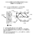
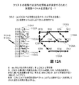
移行の軌跡;心律動障害の根源、すなわちロータまたは限局性拍動の移動が、移行の軌跡とも呼ぶ経路を定義する。この軌跡は、円周(または周縁)によって画定される形状を画定し、この形状は、(任意の心臓組織の3次元を考えたときに)領域の中心および質量中心を有する。図24A〜図28Aに示されるように、移行の軌跡は、ある患者に関して、数ヶ月以上の長期間にわたって一貫していることがある。 Transitional trajectory; the root of the heart rhythm disorder, ie movement of the rotor or focal pulsation, defines a path that is also referred to as the transitional trajectory. This trajectory defines a shape defined by the circumference (or perimeter), which has the center of the region and the center of mass (when considering the three dimensions of any cardiac tissue). As shown in FIGS. 24A-28A, the transition trajectory may be consistent for a patient over an extended period of several months or more.
根源のサイズおよび形状;この用語は、複雑な律動障害の根源(ロータまたは限局性拍動)の移行の軌跡の特徴を表すために使用する。 The size and shape of the source; this term is used to describe the trajectory characteristics of the transition of a complex rhythm disorder source (rotor or focal beat).
成形アブレーション;この用語は、複雑な心律動障害において、移行の軌跡の1つまたは複数の部分、および/または移行の軌跡の近位の1つまたは複数の部分をなくすために、形状を適合させて送達されるアブレーション療法(例えば、外傷)を表すために使用する。これは、根源の移行の軌跡によって画定される領域全体または領域の一部の破壊を含むことがある。あるいは、またはさらに、これは、根源の移行の軌跡(周縁)の近位に位置された(または「近位の」)組織の破壊を含むこともある。例えば、そのような近位の療法(例えばアブレーション)は、周縁上または周縁の内側の少なくとも一部分に対する療法が可能でない、または望ましくない(例えば、その部分が横隔神経に重なる)いくつかの場合に有用となり得る。これらの場合には、周縁の外側にある組織の一部分に療法を送達することによって、根源による心臓の迷走性の活性化を変更または阻止することが望まれることがある。様々な組織厚さ、構造特性、および機能特性を有する心臓の様々な領域内にある様々な形状の根源に関して、特殊化されたカテーテル、電極設計、および手法を使用することができる。 Shaped ablation; the term adapts shape to eliminate one or more portions of the transition trajectory and / or one or more portions proximal to the transition trajectory in complex cardiac rhythm disorders Used to represent ablation therapy (eg trauma) delivered in This may include the destruction of the entire region or a portion of the region defined by the root transition trajectory. Alternatively, or in addition, this may include the destruction of tissue located proximal (or “proximal”) to the root transition trajectory (periphery). For example, such proximal therapy (eg, ablation) is in some cases where therapy to at least a portion on or inside the periphery is not possible or desirable (eg, that portion overlaps the phrenic nerve) Can be useful. In these cases, it may be desirable to alter or prevent the vagal activation of the heart by the source by delivering therapy to a portion of the tissue outside the periphery. Specialized catheters, electrode designs, and techniques can be used for differently shaped root sources in different regions of the heart with different tissue thickness, structural characteristics, and functional characteristics.
近位;この用語は、心律動障害の少なくとも1つの根源によって画定される周縁に関連付けられる生物学的に関連する区域の内部を意味し、根源は、その周縁上または周縁の内側で空間的に移行する。生物学的な関連性は、修正された場合に、心律動障害の根源による心臓の迷走性の活性化に影響を及ぼす区域として定義される。これは、様々な条件と共に変化する。例えば、心房(例えば直径4〜6cm)では、この区域は、根源の周縁から2cm以下、望ましくは1cm以下でよく、または、根源による心臓の迷走性の活性化を変更するのにより小さな区域の修正で十分である場合には、その区域内に定義することができる。より大きな心室(例えば、最大直径約10cmを有する扁長楕円)では、この区域は、2〜3cm以下、望ましくは2cm以下、より望ましくは1.5cm以下でよい。いくつかの実施形態では、用語「近位」は、周縁の内側の領域の1つまたは複数の部分を含むことがある。他の実施形態では、用語「近位」は、周縁の外側の領域の一部分を含むことがある。いくつかの他の実施形態では、用語「近位」は、周縁の内側の領域の一部分と、周縁の外側の領域の一部分とを含む。 Proximal; this term refers to the interior of a biologically relevant area associated with the periphery defined by at least one source of cardiac rhythm disorder, the source spatially on or within that periphery. Transition. Biological relevance is defined as the area that, when modified, affects the vagal activation of the heart by the source of cardiac rhythm disturbances. This varies with various conditions. For example, in the atrium (eg, 4-6 cm in diameter), this area may be no more than 2 cm, preferably no more than 1 cm from the periphery of the source, or a smaller area modification to alter the vagal activation of the heart by the source. Can be defined within that area. In larger ventricles (eg, oblong ellipses with a maximum diameter of about 10 cm), this area may be 2-3 cm or less, desirably 2 cm or less, more desirably 1.5 cm or less. In some embodiments, the term “proximal” may include one or more portions of the inner region of the periphery. In other embodiments, the term “proximal” may include a portion of the outer region of the periphery. In some other embodiments, the term “proximal” includes a portion of the inner region of the periphery and a portion of the outer region of the periphery.
本発明の発見以前には、ヒトの生物学的律動障害、特に心律動障害の原因は識別されていなかった。本発明は、ヒトの生物学的障害を持続させる、永続化する、または「誘発」する原因を、正確に最小侵襲で検出し、診断し、その後、効果的に治療する方法を述べた、知られている最初の事例である。この方法により、医師は、これらの根源を標的とし、周囲の重要でない組織に対する標的または損傷を最小限にしながら律動障害を修正または解消してなくすことができるようになる。いくつかの実施形態は、心律動障害(例えば心臓パルス発生源)に対する最小侵襲性処置に関するものであるが、本発明は外科的療法に適用することもでき、また、脳などの臓器、中枢神経系(癲癇や発作の原因を位置特定することができる)、末梢神経系(腫瘍を検出することができる)、骨格筋、平滑筋、例えば胃腸管、膀胱、および子宮、ならびに他の臓器における電気パルス発生または伝播の障害に対して適用することもできる。 Prior to the discovery of the present invention, the cause of human biological rhythm disorders, particularly cardiac rhythm disorders, has not been identified. The present invention describes a method for accurately and minimally invasively detecting, diagnosing, and then effectively treating a cause that persists, perpetuates, or “triggers” a human biological disorder. This is the first case. This method allows the physician to target these sources and to correct or eliminate rhythm disturbances while minimizing the target or damage to surrounding unimportant tissue. Although some embodiments relate to minimally invasive procedures for cardiac rhythm disorders (eg, cardiac pulse sources), the present invention can also be applied to surgical therapy, as well as organs such as the brain, central nervous system Electricity in the system (can locate the cause of epilepsy or seizures), peripheral nervous system (can detect tumors), skeletal muscle, smooth muscle such as the gastrointestinal tract, bladder, and uterus, and other organs It can also be applied to pulsation or propagation faults.
本発明の一実施形態によれば、様々な空間分解能および視野で、したがって感知チャネルの数を変えるための装置を用いて、ヒトの心臓などヒトの臓器内の複数の位置から信号をサンプリングするための装置、例えば電極カテーテルなどのセンサデバイスが開示される。 In accordance with one embodiment of the present invention, for sampling signals from multiple locations within a human organ, such as the human heart, using devices for varying the number of sensing channels at various spatial resolutions and fields of view. A device such as an electrode catheter is disclosed.
本発明の一実施形態によれば、AF、VF、および多形性VTなど複雑な律動を含めた空間的に移行する心律動障害に関する電気ロータ、限局性拍動、および他の局所化された原因を識別して局所化するための方法が開示される。 According to one embodiment of the present invention, electrical rotors, localized pulsations, and other localized localized spatially migrating heart rhythm disorders, including complex rhythms such as AF, VF, and polymorphic VT A method for identifying and localizing causes is disclosed.
本発明の実施形態は、活性化トレールを生成するための活性化シーケンスの順序付けなどのプロセスおよびソフトウェア方法、ヒルベルト変換などのプロセス、他の位相遅延法、空間コヒーレンス解析、および他の方法を使用することができる。 Embodiments of the present invention use processes and software methods such as ordering of activation sequences to generate activation trails, processes such as Hilbert transform, other phase delay methods, spatial coherence analysis, and other methods. be able to.
本発明の一実施形態では、センサから収集されて分析されるデータは、自動的に更新されるデータベースにデータとして記憶される。このデータベースは、医師が局所化された原因の診断/検出を行うのを補助するため、または律動障害の原因のパターンを分類するために使用される。このデータベースは、特定の特徴を有する患者における原因の確率分布マップの形態を取ることができる。 In one embodiment of the invention, the data collected and analyzed from the sensors is stored as data in an automatically updated database. This database is used to assist physicians in diagnosing / detecting localized causes or to classify patterns of rhythm disturbance causes. This database can take the form of a probability distribution map of causes in patients with specific characteristics.
本発明の別の実施形態によれば、医師が治療を行うのを補助することができる形式で生物学的律動障害に関する原因を表示するための装置が提供される。例えば、視覚表示画面を処理装置に接続することができ、活性化トレールの閲覧を可能にし、また、ロータのコア、限局性の根源、または障害の他の原因の視覚的な位置特定を可能にする。また、音声形式を、単独で、または視覚形式と組み合わせて使用することもできる。例えば、コアを視覚的に識別することができるようにする根源の視覚的な描写に加えて、またはその代わりに、障害の位置および原因に関して、根源およびそのコアの座標を音声表示によって使用者に提供することができる。視覚的な描写が特に望ましい。なぜなら、視覚的な描写は、術者に原因の明瞭な表現を提供し、また原因のコアを識別するための基準を提供し、これが治療の選択を大幅に容易にするからである。例えば、実際のロータまたは限局性拍動と、空間的に移行するロータまたは限局性拍動によって画定される領域(例えば周縁)との視覚的表現により、術者は、アブレーションカテーテルまたは他の治療をどこに向けるかを正確に決定することができるようになる。 In accordance with another embodiment of the present invention, an apparatus is provided for displaying causes related to biological rhythm disorders in a manner that can assist a physician in performing treatment. For example, a visual display screen can be connected to the processing unit, allowing viewing of the activated trail, and visual localization of the rotor core, localized roots, or other causes of failure To do. Also, the audio format can be used alone or in combination with a visual format. For example, in addition to or instead of a visual depiction of the source that allows the core to be visually identified, the source and the coordinates of the core are displayed to the user by audio display regarding the location and cause of the fault. Can be provided. A visual depiction is particularly desirable. This is because the visual depiction provides the operator with a clear representation of the cause and provides a basis for identifying the core of the cause, which greatly facilitates treatment choice. For example, a visual representation of the actual rotor or focal beat and the area defined by the spatially moving rotor or focal beat (e.g., the periphery) allows the operator to perform an ablation catheter or other treatment. You will be able to determine exactly where you want to go.
本発明の別の実施形態によれば、障害の原因(空間的に移行する原因も含む)が識別されると、律動障害を治療または解消するために、識別および局所化された根源と関連付けられた心臓組織の領域を修正または破壊するための治療デバイスまたは方法の使用を採用することができる。治療デバイスおよび方法の非限定的な例としては、アブレーションカテーテルなどによる破壊エネルギーの使用(アブレーション)、外科的アブレーション法、外科的切除、または埋め込んだリードや他の物理的なデバイスなど心臓内でのデバイスの使用、刺激エネルギー(ペーシング)、薬理剤の直接の送達、細胞療法、または他の介入技法が挙げられる。一実施形態では、身体、特に心臓からの信号を感知することができるカテーテルが、アブレーションエネルギー、刺激エネルギー、薬物療法、幹細胞などの細胞療法、遺伝子療法、または他の治療手段を送達することができる機能など、治療手段を含むこともできる。したがって、そのようなカテーテルは、障害の検出と治療どちらにも採用することができる。 According to another embodiment of the present invention, once the cause of the disorder (including the cause of spatial transition) is identified, it is associated with the identified and localized root to treat or resolve the rhythm disorder. The use of a treatment device or method for modifying or destroying a region of the damaged heart tissue can be employed. Non-limiting examples of treatment devices and methods include the use of disruptive energy (ablation), such as an ablation catheter, surgical ablation, surgical excision, or implanted leads or other physical devices in the heart Use of devices, stimulation energy (pacing), direct delivery of pharmacological agents, cell therapy, or other interventional techniques. In one embodiment, a catheter capable of sensing signals from the body, particularly the heart, can deliver ablation energy, stimulation energy, drug therapy, cell therapy such as stem cells, gene therapy, or other therapeutic means. It can also include therapeutic means such as function. Thus, such catheters can be employed for both fault detection and treatment.
本発明は、複雑な心律動障害の検出、診断、および治療に特に適している。そのような心律動障害は、例えば、VF、多形性VT、トルサードドポアン、およびAFであり、局所化された原因が正確に識別されて位置を示されると、局所化された原因(移動する原因も含む)に対する正確な、狙いを定めたアブレーションを実施することができる。上で論じたように、原因の識別および物理的な位置特定は以前は行うことができず、したがって、熟練した術者にとってさえ、治療を成功させることは非常に難しく、実質的に改善または解消できることははるかに少なかった。 The present invention is particularly suitable for the detection, diagnosis and treatment of complex cardiac rhythm disorders. Such cardiac rhythm disorders are, for example, VF, polymorphic VT, torsade de pointes, and AF, and if the localized cause is correctly identified and located, the localized cause (movement Accurate and targeted ablation can be performed. As discussed above, cause identification and physical localization has not previously been possible, and therefore, even for a skilled surgeon, it is very difficult to achieve a successful treatment and substantially improve or eliminate There was much less we could do.
複雑な心律動障害の原因(移動する原因も含む)を所見または識別し、続いて治療することに加えて、本発明はまた、術者のために、分析を高速化および単純化することによって、ただ1つの部位から発散する「単純な」律動の診断および治療を補助するために適用することもできる。心律動障害に関して、そのような単純な障害としては、限局性心房頻拍、多源性心房頻拍(MAT)、洞房結節リエントリまたは不適切洞性頻拍、心室頻拍(VT)、心房性期外収縮(PAC)、および心室性期外収縮(PVC)が挙げられる。 In addition to finding or identifying and subsequently treating the causes of complex cardiac rhythm disorders (including moving causes), the present invention also provides for the operator by speeding up and simplifying the analysis. It can also be applied to aid in the diagnosis and treatment of “simple” rhythms emanating from a single site. With respect to cardiac rhythm disorders, such simple disorders include localized atrial tachycardia, multisource atrial tachycardia (MAT), sinoatrial node reentry or inappropriate sinus tachycardia, ventricular tachycardia (VT), atrium. Mental extrasystole (PAC), and ventricular extrasystole (PVC).
本発明には、感知デバイスおよび記録システムを含めた、データを収集するためのプロセスおよびシステムが含まれる。収集されたデータは、少なくとも、1つまたは複数の信号を送信した各センサの位置と、各活性化信号または活性化期間が生じた開始時点とを含む。処理装置は、この情報を受信し、活性化開始時点を逐次に順序付けする。この計算の結果により、活性化トレールが生成され、これは、障害に関するシグネチャパターンを生成し、障害に対する原因の位置とタイプ両方を示す。すなわち、ロータであるか、限局性の根源であるか、または散逸パターンである(すなわち局所化された根源がなく、したがって心臓の別の領域または他の身体領域からさらなるデータを収集する必要がある)かを示す。このようにして順序付けを成されたデータ(たとえば律動障害の根源)は、活性化トレールを生成し、これは、視覚ディスプレイ上に視覚的に表示することができ、ロータ根源の場合にはロータの実際の回転パターンを示し、それによりロータのコアが視覚的に明らかになり、容易に識別し、したがって治療することができる。限局性拍動など半径方向に発散する根源の描写にも同じことが当てはまる。各センサにおける活性化開始時点の逐次の順序付けは、限局性律動障害の位置特定を可能にし、それにより、視覚ディスプレイ上で限局性コアを容易に位置特定して、狙いを定めた正確な治療を行うことができる。望ましくは、律動障害の根源または原因はある期間にわたって表示されて、術者が原因の点または領域を十分良く観察できるようにし、また原因の位置での適切な治療に関する快適な評価を行うことができるようにする。空間的に移行する根源に関して、移行する根源の大きさを識別するために、そのような根源の周りの周縁を決定して、視覚的に示すことができる。一実施形態では、データ、および/または処理されたデータの視覚表示(すなわち活性化トレールの「動画」)が、律動障害の原因のシグネチャパターンを明らかにする。そのような記憶された情報は、術者が以前のパターンを調べることができるようにし、同様の原因の識別、局所化、および治療を改善する助けとなる。いくつかの例では、そのような記憶された情報は、測定されたリアルタイムデータの外挿を可能にして予測モデルを提供するか、またはいくつかの測定されたパターンを、同様の既知のパターンを用いて明瞭にする。 The present invention includes processes and systems for collecting data, including sensing devices and recording systems. The collected data includes at least the location of each sensor that transmitted one or more signals and the starting point at which each activation signal or activation period occurred. The processing device receives this information and sequentially orders activation start points. The result of this calculation generates an activation trail that generates a signature pattern for the fault, indicating both the location and type of the cause for the fault. That is, it is a rotor, a localized source, or a dissipative pattern (ie there is no localized source, so additional data needs to be collected from another region of the heart or other body region ) The data ordered in this way (eg the source of rhythm disturbances) generates an activation trail, which can be visually displayed on a visual display, and in the case of a rotor source the rotor's It shows the actual rotation pattern, so that the core of the rotor is visually evident and can be easily identified and therefore treated. The same applies to the depiction of roots that diverge in the radial direction, such as focal beats. The sequential ordering of activation on each sensor allows localization of localized rhythm disorders, which makes it easy to locate the localized core on a visual display for targeted and accurate treatment. It can be carried out. Desirably, the source or cause of the rhythm disorder is displayed over a period of time so that the operator can observe the point or area of the cause well enough and make a comfortable assessment of the appropriate treatment at the location of the cause. It can be so. For spatially moving sources, the perimeter around such sources can be determined and visually indicated to identify the size of the migrating sources. In one embodiment, a visual display of data and / or processed data (ie, an “animation” of the activation trail) reveals the signature pattern that causes the rhythm disorder. Such stored information allows the operator to examine previous patterns and helps improve similar cause identification, localization, and treatment. In some examples, such stored information allows extrapolation of measured real-time data to provide a predictive model, or several measured patterns, similar known patterns Use for clarity.
本発明のさらなる実施形態は、原因が存在する組織を大抵は修正または破壊することによってそのような原因の治療を行うためのプロセスおよびシステムを提供する。一実施形態では、1つの好ましい実施形態は、本発明を、患者を治療する処置中に直接使用するのではなく、「オフライン」の非リアルタイム検討モードで使用することができる。他の実施形態では、本発明は、処置中に、リアルタイムモードで術中に使用して、律動障害の原因を好適に発見および治療することができる。 Further embodiments of the present invention provide processes and systems for treating such causes, usually by modifying or destroying the tissue in which the cause exists. In one embodiment, one preferred embodiment may use the present invention in an “off-line” non-real-time review mode, rather than directly during a treatment to treat a patient. In other embodiments, the present invention can be used intraoperatively in a real-time mode during a procedure to suitably find and treat the cause of rhythm disorders.
本発明のプロセスおよびシステムは、生物学的律動障害のために使用することができる。具体的には、本発明のプロセスおよびシステムを採用して、脳波図または他の指標を使用して、脳または中枢神経系での異常な電気パルス発生または伝播の根源を局所化し(すなわち原因の物理的な位置を見出し)、発作もしくは癲癇または限局性腫瘍(悪性または良性)を識別して治療できるように侵襲性療法(手術)または外部ビーム照射を案内することができる。本発明はまた、横紋筋(骨格筋の損傷など)、消化管系(食道痙攣など)、泌尿生殖器系、および呼吸器系、または他のヒトの器官や系での異常パルス伝播に関する根源を識別するために使用することもできる。本発明はまた、任意の身体系における腫瘍(悪性または良性)を検出するために使用することもできる。本発明はまた、レーダーまたはソナーなどの方法と併用して、地震事象の根源を位置特定する、またはエネルギー源を位置特定するなど、医学以外の用途もある。 The processes and systems of the present invention can be used for biological rhythm disorders. Specifically, employing the processes and systems of the present invention, an electroencephalogram or other indicator is used to localize (i.e., cause of) abnormal electrical pulse generation or propagation in the brain or central nervous system. Finding the physical location), guiding invasive therapy (surgery) or external beam irradiation so that seizures or epilepsy or localized tumors (malignant or benign) can be identified and treated. The present invention also provides a source for abnormal pulse propagation in striated muscle (such as skeletal muscle damage), gastrointestinal system (such as esophageal spasm), urogenital system, and respiratory system, or other human organs and systems. It can also be used to identify. The present invention can also be used to detect tumors (malignant or benign) in any body system. The invention also has non-medical applications such as locating the source of seismic events or locating energy sources in conjunction with methods such as radar or sonar.
本発明は、そのプロセス、およびプロセスを実施するためのシステムに関していくつかの態様を有する。例として、限定はしないが、本発明の一態様では、律動障害時に、前記感知の明瞭性を最適にするためにセンサの間隔を変えて、臓器内の複数の位置から信号が検出される。また、特に望ましい実施形態は、律動障害中に、心臓または他の身体部分からのこれらの信号を記録して、データベースに記憶する。特定の信号に関連付けられた各センサの位置と、各センサでの活性化開始時点とが、処理装置に伝送されて、逐次の順序付けを含めた分析が行われ、障害の原因および体内でのその具体的な位置を識別する活性化トレールを生成する。手動または自動で更新することができる原因のデータベースを作成することにより、障害の原因の識別および局所化を補助するためにデータベースにアクセスすることができるようになる。これは、現在の患者でのデータ収集の質が限られているときに使用され、ある患者でのパターンを、その患者に関して以前に記録された律動と比較して、律動が同じであるか異なるかを判断する。あるいは、ある患者でのパターンを、同様の臨床的特徴を有する者など別の患者からのパターンと比較する。以前の症例からの以前に記憶されたデータを使用して、現在の症例での律動障害に関する原因の識別、局所化、および表示を補助することができる。 The present invention has several aspects with respect to the process and the system for performing the process. By way of example but not limitation, in one aspect of the invention, signals are detected from multiple locations within an organ with varying sensor spacing to optimize the clarity of the sensing during rhythm disturbances. Also, particularly desirable embodiments record these signals from the heart or other body parts during rhythm disturbances and store them in a database. The position of each sensor associated with a particular signal and the activation start time for each sensor are transmitted to the processing unit for analysis, including sequential ordering, to determine the cause of the disorder and its An activation trail that identifies a specific location is generated. Creating a cause database that can be updated manually or automatically allows access to the database to assist in identifying and localizing the cause of the failure. This is used when the quality of data collection in the current patient is limited, comparing the pattern in a patient to the previously recorded rhythm for that patient, and the rhythm is the same or different Determine whether. Alternatively, a pattern from one patient is compared to a pattern from another patient, such as one with similar clinical characteristics. Previously stored data from previous cases can be used to assist in identifying, localizing, and displaying causes for rhythm disorders in the current case.
律動障害の根源と、律動障害の移行性の根源を画定する領域とを視覚的に表示することは、術者にとって非常に有用である。なぜなら、これは、原因の存在および位置に関する視覚的な案内として働き、律動障害を改善または解消するために、狙いを定めた正確な後の治療を可能にするからである。 It is very useful for the surgeon to visually display the root of the rhythm disorder and the area that defines the migratory root of the rhythm disorder. This is because it serves as a visual guide for the presence and location of the cause and allows targeted and accurate subsequent treatment to improve or eliminate rhythm disturbances.
本発明の他の態様では、別の症例からの以前に記憶されたデータを使用して、現在の症例での律動障害に関する原因を識別、局所化、および表示することができる。次いで、これを使用して、将来の処置での本発明の使用を計画することができる。 In other aspects of the invention, previously stored data from another case can be used to identify, localize, and display causes related to rhythm disorders in the current case. This can then be used to plan the use of the invention in future treatments.
有用な構成要素、モジュール、およびデバイスの説明
図1は、本発明のプロセスおよびシステムで使用することができる様々な有用な構成要素(モジュール)の概略図を示す。モジュールは、互いに別個であり、それらの機能を提供するために協働してインターフェースすることができる。あるいは、それらの1つまたは複数が互いに一体化されて処理装置内に含まれていてもよく、それによりシステムは、あまり分かれていないハードウェアユニットを有する。図1は、最小侵襲性の経皮的処置中、または他の処置中、例えば体表面ECGの使用、心磁図の使用、あるいは超音波、電磁放射、音波、マイクロ波、もしくは電気インピーダンス変化からの心エコーおよび/またはドップラー測定の使用中に障害の原因を局所化できるようにする一実施形態を示す。
Description of Useful Components, Modules, and Devices FIG. 1 shows a schematic diagram of various useful components (modules) that can be used in the processes and systems of the present invention. Modules are separate from each other and can be interfaced cooperatively to provide their functionality. Alternatively, one or more of them may be integrated into one another and included in the processing device, so that the system has hardware units that are not very separate. FIG. 1 may be used during minimally invasive percutaneous procedures, or other procedures, such as from the use of body surface ECG, the use of a magnetocardiogram, or changes in ultrasound, electromagnetic radiation, sound waves, microwaves, or electrical impedance FIG. 4 illustrates one embodiment that allows localization of the cause of a disorder while using echocardiographic and / or Doppler measurements. FIG.
図1において、心臓10内での電気的事象が、感知電極を用いて記録される。これらの電極は、図2〜図4に例示されるカスタム設計の記録カテーテルを含めた、心臓の内腔または脈管構造の内部に配置された1つまたは複数のカテーテル20でよい。また、電極は、埋込型ペースメーカーもしくは電気除細動機−細動除去器からのリード線の延長部でよく、典型的には大静脈20〜21もしくは冠状静脈洞22を通って到達する単相活動電位もしくは他の信号を記録するために使用されるカテーテルでもよい。したがって、本発明のプロセスおよびシステムは、活性化時点およびそれらの発生位置を正確に伝送することができる体内または体外で使用される任意のカテーテルまたは感知デバイスを採用することができるので、本発明において特に有用ではあるが図2〜図4の特殊化されたカテーテルを採用する必要は必ずしもない。
In FIG. 1, electrical events within the
電極23は、冠状静脈洞内の電極21によってアクセスされた心臓の心外膜または心膜の表面から、心膜空間または他の経路内の電極23を介して記録することができる。電極は、左心房および左心室内に位置することがある心臓15を支配する神経の近位に位置させることができる。電極は、コンピュータ化されたマッピングシステムからの仮想(計算された)電極、ルーチンもしくは高分解能ECGマッピング電極30、皮下に埋め込まれた電極もしくは皮膚上の電極、または心臓もしくは身体に直接接触することなく信号を非侵襲性で検出するための方法における電極でよい。また、電極情報は、データベース160内に記憶されている電位図から導出することもできる。
The
心臓の近くに配置された電極25を使用して、律動障害に関する原因の近くにある、または原因の位置にある領域を修正または破壊することができる。電極がアブレーションカテーテルである場合、エネルギー発生器60にインターフェースする。他の電極は、制御装置40およびペーシングモジュール50とインターフェースすることがあり、すべての電極が望ましくはプロセス制御装置70と連絡する。アブレーションまたはペーシングは、心臓の多くの位置にある心臓15を支配する神経に向けることができる。内部アブレーション電極を外部アブレーションシステムで置き換えることもでき、そのようなシステムは、例えば、手術中の外部プローブ、または癌療法に関しては外部集光照射または光子ビームにおけるものである。さらに、根源の修正、すなわち障害の原因の治療は、適切な薬理組成物、遺伝子療法、細胞療法を送達することによって、または(手術で、もしくは特殊なデバイスを使用して)組織を切除することによって実現することができる。
An
プロセス制御装置70は、様々な構成要素またはモジュールを含むことがある。1つのそのような構成要素またはモジュールとしてサンプリングモジュール80があり、このモジュール80は、律動障害中に信号を記録する、(ペーシングによって)律動障害時ではないときに様々なレートで記録する、および/または(ペーシングまたは他の方法によって)心律動障害をシミュレートするレート中に記録することができる。信号増幅器(図示せず)を使用して信号の明瞭性および強度を高めることができ、また、プロセス制御装置は、原因を識別して局所化できるように十分な数の位置から感知するために最小数の記録増幅器を知的に割り当てることもできる。例えば、システムは、128個のセンサ(例えば2つの市販の多極カテーテル)から記録するために50〜60個の物理的な増幅器チャネルのみを使用することがあり、これは、タイムスライシングによって「タイムシェア」ベースでそれら128個のセンサを記録することによって、または律動の原因に近い個々の/複数のセンサを活動化させ、他のものは非活動化させることによって行われる。この「切替え」機能は、切替え構成要素によって行うことができ、切替え構成要素は、センサデバイスを電子制御システムと接続し、1つまたは複数の他の構成要素で具現化することができる。切替えは、手動でも自動でもよく、例えば、心律動障害の原因の場所に基づいて決定される。モジュール90は、ペーシングモジュールとインターフェースして追加の心拍数を提供し、生体信号を感知する。これは、本明細書で説明する非リアルタイムモード(モード6)に関して特に有用である。なぜなら、特定の心律動障害が診断および治療されないときでさえ、様々な心拍数で心臓を検査することができるからである。
本発明による方法およびシステムは、収集されたデータを、分析モジュールによって行うことができる分析法を使用して処理する。例えば、図1で、モジュール100は「分析エンジン」の部分Iである。分析エンジンのこの部分は、各感知位置で、時間にわたって生物学的信号に関する開始および終了を決定する。これは、時間にわたって律動中に一連の活性化時点(開始タイミング)およびリカバリ時点(終了タイミング)を生成することによって実施される(図6に示される)。信号は、典型的には、時間にわたる電圧として(すなわち、電圧−時間系列として)表される。活性化時点は、多くの方法で処理することができる。最も単純なものとしては、各位置での手動の割当てがある。最大の立ち上がりまたは立ち下がりを示すために2次導関数の最大値、最小値、またはゼロを定義するために1次導関数のゼロを使用することによって、自動化または計算された割当てを実現することができる。また、活性化開始時点および終了時点は、電圧−時間系列がしきい値を横切るときに割り当てることもできる。活性化時点を割り当てるための別の可能な方法は、パターンマッチングの使用である。例えば、活性化期間を表すために選択されるパターンを、時間にわたって複数の時点で信号に相関させることができる。前記相関値が高い時間は、前記テンプレートの再発生を示し、したがって活性化時点とみなされる。また、この分析に使用されるテンプレートは、データベース内に記憶されているデータから得ることもでき、またはその位置での律動に関するレート推定値から計算することもできる。信号品質が雑音の多いものであるとき、低品質であるとき、または異なる時間に複数の成分を示すとき、複数のセンサからの同時記録は、特にAFやVFなど複雑な律動に関して活性化を分析する助けとなることがある。同時記録から、好ましくは分析されるチャネルに近い位置で基準信号が選択される。基準チャネルでの信号を使用して、分析されるチャネルでの信号または信号成分を選択する。これは、パターンマッチングもしくは相関関数、ベクトル解析、または他の方法を使用して、時間にわたって同様のタイミングを保つ成分を使用することによって行うことができる。多くの方法が必要とされる場合、心房の既知の病態生理学的特徴による制約の下で、ヒューリスティック、パターン認識法、およびいわゆる「ファジー論理」手法を適用することができる。
The method and system according to the present invention processes the collected data using analytical methods that can be performed by the analysis module. For example, in FIG. 1,
モジュール110は、分析エンジンの部分IIであり、これは、心律動障害に関する根源(原因)の存在および位置を実際に計算して局所化する、すなわち特定する。
本発明のいくつかの実施形態は、「療法エンジン」を含み、これは、システムおよびプロセスで様々な機能を協働して行うように設計されたより多くのモジュールのうちの1つを含むことがある。例えば、図1でのモジュール120は、心臓内での律動障害に関する根源の位置および移動パターンの決定を担当することができる。モジュール120は、療法エンジンの第1のモジュールでよく、これを使用して、律動障害を治療または解消するために修正する必要がある位置および空間領域を計算する。治療は、本明細書で論じるようにアブレーションエネルギーまたは他の手段の送達によるものでよく、アブレーション中に根源が移動する場合には単純に1点または1領域ではない。モジュール130は、療法エンジンの別のモジュールを表し、望ましくは、プロセス制御装置を介してエネルギー発生器60と直接インターフェースして、根源である見込みが高い部位で組織をアブレート(破壊)、修正(アブレーションもしくはペーシング)、または刺激(ペーシング)する。あるいは、モジュール130を使用して、例えば薬理剤または遺伝子療法もしくは細胞療法を送達することによって、破壊エネルギーなしで組織を修正することができる。
Some embodiments of the present invention include a “therapy engine”, which may include one of more modules designed to cooperate in performing various functions in the system and process. is there. For example, the
図1に示されるシステムのモジュール170は、医師が律動障害を治療または解消するのを補助するために、視覚的にまたは音声で原因(空間的に移行する原因も含む)の識別または位置を表示するためのツールを表す。例えば、このモジュールは表示画面を含むことがあり、これにより、障害のロータ、限局性の原因、または他の原因、ならびに障害の移行性の原因を文字、画像、および/または音声によって画面上に可視化したものを術者が明瞭に見ることが可能になる。いくつかの実施形態では、見つかった律動障害の「動画」クリップが画面上に表示される。この動画クリップは、障害の実際の原因(移行性の原因を含む)および位置のリアルタイム表現である。例えば、本発明のプロセスに従ってデータの分析が行われた後、すなわち、信号の位置およびそれらの活性化開始時点が逐次に順序付けされた後、この分析および計算の結果が、活性化トレールの形で画面上に示され得る。活性化トレールのパターンが、中心コアの周りで回転する一連の活性化を表す場合、ロータが所見されており、実際にそれが障害の原因である。同様に、活性化トレールのパターンが、中心コア領域から半径方向に発散する一連の活性化を表す場合、限局性拍動が所見されており、実際にそれが障害の原因である。したがって、本発明によるプロセスは、術者に対して、障害の原因の直接の所見、ならびに障害の存在、タイプ、および位置の簡便な視覚化を可能にする。判別可能なパターンが所見されない場合、すなわち活性化トレールが局所化されない場合、センサ位置を移動させることによって、および/または既に配置されているセンサをオンに切り替えることによって追加の信号サンプリングを行うことが適切であることがある。次いで、追加の信号サンプルを本発明に従って処理して、画面上に示すことができる。データの追加のサンプリングおよび処理によって原因が所見された場合、適切な治療に関する決定を下すことができる。散逸した活性化トレールおよびパターンが所見された場合、術者が十分であると感じる時間までさらなる追加のサンプリングを行うことが賢明であることがある。いくつかの例では、プロセスの結果が、ロータまたは半径方向に発散する病巣の存在および位置の所見となる。サンプリングおよび処理を繰り返した後でさえ散逸パターンが残る他の例では、原因としてロータまたは限局性拍動を除外するという診断を下すことができる。したがって、ロータまたは限局点(拍動)の所見は、本質的に検出と診断を同時に行い、一方、そのような所見がないときは、障害のこれらの原因の存在をいずれも除外することができるという診断が下される。
The
モード1 信号サンプリング(図1、参照番号80)
信号サンプリングは、律動障害をアブレートまたは治療するための処置中、処置に関する計画前、または障害の検討後に、リアルタイムで行うことができる。上述したように、信号は、様々なセンサタイプを使用して臓器から1つまたは複数の位置で収集される。接触センサが、組織との接触をできるだけ良好に保つべきである。好ましいモードでは、電極は、複数の部位で同時に、またはほぼ同時に記録すべきである。AFなど最も速い心律動障害は、サイクル長>100msを有し、したがって、この時間よりも実質的に短い時間での信号獲得が「ほぼ同時」とみなされる。代替の動作モードは、一連の部位へのセンサの移動を可能にする。本発明は、任意の既存のセンサ装置またはデバイスと共に使用することもできる。
Signal sampling can be performed in real time during a procedure to ablate or treat a rhythm disorder, before planning the treatment, or after reviewing the disorder. As described above, signals are collected at one or more locations from the organ using various sensor types. A contact sensor should keep the contact with the tissue as good as possible. In the preferred mode, the electrodes should be recorded at multiple sites simultaneously or nearly simultaneously. The fastest cardiac rhythm disturbances, such as AF, have a cycle length> 100 ms, so signal acquisition in a time substantially shorter than this time is considered “nearly simultaneous”. Alternative modes of operation allow movement of the sensor to a series of sites. The present invention can also be used with any existing sensor apparatus or device.
信号サンプリングを得るために様々な市販の電極デバイスを使用することができるが、信号サンプリングのために特に有用なデバイス実施形態を図2〜図4に示す。これらのデバイスは複数のセンサを使用し、センサは、個別に活動化または非活動化することができ、または相互に移動させることができる。これは、センサ間隔を望みに応じて増減させることができるので、適応空間分解能を可能にする。間隔を広く空けられたセンサは、広い視野を提供して、臓器(例えば心臓の左心房)の大きな部分に関して律動を「調査」する。根源の位置に近付くと、望ましくはセンサ間隔を狭めるように構成が変えられて、狭い視野にわたるより高い空間分解能となる。狭い間隔のセンサ構成は、律動障害の根源を治療するために、合焦した領域にエネルギーを印加するのに好ましい。 Although various commercially available electrode devices can be used to obtain signal sampling, device embodiments that are particularly useful for signal sampling are shown in FIGS. These devices use multiple sensors, which can be activated or deactivated individually or moved relative to each other. This allows for adaptive spatial resolution because the sensor spacing can be increased or decreased as desired. A widely spaced sensor provides a wide field of view and “investigates” the rhythm for a large portion of an organ (eg, the left atrium of the heart). As the location of the source is approached, the configuration is preferably changed to reduce the sensor spacing, resulting in higher spatial resolution over a narrow field of view. Narrow spacing sensor configurations are preferred for applying energy to the focused area to treat the source of rhythm disturbances.
適応空間分解能は、本発明の様々な実施形態の重要な利点である。これは、センサを物理的に移動させることによって実現することができる。図2は、信号を感知し、いくつかの例ではエネルギーまたは他の治療療法を送達するための複数の感知要素(電極またはプローブ)(要素205)を備える同心螺旋(要素200)を示す。螺旋200は、カテーテルの一部がシャフト(要素215)の内部で展開しないままである(要素210)ときに広く間隔を空けられる。アセンブリを回転および前進させることで、より多くのプローブを内腔内に導入し、プローブの間隔を狭める。図3は、調節可能なファンカテーテルの形態での本発明によるセンサカテーテルの別の実施形態であり、複数の経線(要素230)がそれぞれ複数の感知要素(電極またはプローブ)(要素240)を含み、感知要素は、ここでも感知を行い、いくつかの例ではエネルギーまたは他の治療療法を送達する。図3に示されるように、シャフト軸(要素245)に沿ったねじりまたはひねり運動の組合せによって、経線は、間隔をより広くすることも(要素230)、間隔をより狭くすることも(要素235)でき、すなわち空間的に調節することができる。
Adaptive spatial resolution is an important advantage of various embodiments of the present invention. This can be achieved by physically moving the sensor. FIG. 2 shows a concentric helix (element 200) comprising a plurality of sensing elements (electrodes or probes) (element 205) for sensing signals and in some instances delivering energy or other therapeutic therapies. The
図4は、調節可能なコルク抜きのような設計形状での本発明によるセンサカテーテルの別の実施形態を示し、少数の螺旋経線(要素260)が、鋭利でない非外傷性端部(要素270)で終端する。図2および図3の設計構造と同様に、図4の経線も、複数の要素(電極またはプローブ)(要素265)を含むことがある。シャフト(要素280)を操作することによってこのコルク抜き形状をシース内で前進後退させて、コルク抜き形状のサイズおよび/またはプローブ間隔を増減させることができる。これらの設計は、AFなどの律動に関する根源であり得るより大きいまたはより小さい臓器(例えば様々な大きさの心房)、または肺静脈もしくは上大静脈を含めた副次構造に適合するように、より大きくまたはより小さくすることができる。物理的な移動は、医師によって手動で、または機械を使用することによって自動で実現することができる。本発明者らによって観察された心律動障害に関する根源の観察された特性に鑑みて、センサが、心臓の1つまたは複数の内腔それぞれの表面積の少なくとも約25%から感知することが望ましい。これらの設計は、例示にすぎず、本発明の実際の物理的な設計または用途を限定する意図はない。 FIG. 4 shows another embodiment of a sensor catheter according to the present invention in a design shape such as an adjustable corkscrew, where a small number of helical meridians (element 260) are non-sharp atraumatic ends (element 270). Terminate with Similar to the design structure of FIGS. 2 and 3, the meridian of FIG. 4 may include multiple elements (electrodes or probes) (elements 265). By manipulating the shaft (element 280), this corkscrew shape can be advanced and retracted within the sheath to increase or decrease the corkscrew shape size and / or probe spacing. These designs are more tailored to accommodate larger or smaller organs (eg, variously sized atriums), or collateral structures including pulmonary veins or superior vena cava that can be the source for rhythms such as AF. Can be larger or smaller. Physical movement can be accomplished manually by a physician or automatically by using a machine. In view of the observed characteristics of the source for cardiac rhythm disturbances observed by the inventors, it is desirable for the sensor to sense from at least about 25% of the surface area of each of the one or more lumens of the heart. These designs are exemplary only and are not intended to limit the actual physical design or application of the invention.
各センサに関する最適な接触は、適切性を様々な方法でプロセス制御装置70によって監視することができる。例えば、プロセス制御装置70は、感知された信号の振幅の安定性によって接触を検証することができる。あるいは、プロセス制御装置70は、電極20〜30を介して信号を放出し、誘発された応答の振幅を使用して接触を検証するように、ペーシングモジュール50を調整することができる。第3の代替形態として、処理モジュール70は、(例えばペーシングが可能でないAFにおいて)安定な組織インピーダンスを確認することによって接触を確かめることができる。他の代替形態として、軽度外傷パターンを検査するように設計された、または接触力を直接測定するように設計されたカテーテルを使用することができる。さらに、カテーテル操作は、ロボットによって半自動または自動で制御することができ、また手動で制御することもできる。
Optimal contact for each sensor can be monitored by
適応空間分解能は、電子的に実現することもできる。この調節可能なセンサデバイスでのセンサが、個々のセンサを活動化または非活動化することができる電子制御システムに接続される。これは、医師が臓器の一領域のみに焦点を合わせることを望む場合などに手動で行うことができ、または、心律動の根源が存在する場所と判断された領域に焦点を合わせるように図1のプロセス制御装置によって自動的に行うことができる。電子的切替え装置が、センサと電子制御システムの接続の独立した切替えを制御して、実際の増幅器チャネルの数の使用を最大にする。これらの電子構成要素は、従来の(有線)電極、光ファイバ、エッチングウェハ回路設計、生物学センサ、化学センサ、薬理センサ、圧電センサ、赤外線センサ、患者に適合した光学撮像、オプトロード(optrodes)、遠隔センサ、および他の設計の様々な組合せによって具現化することができる。 Adaptive spatial resolution can also be realized electronically. Sensors in this adjustable sensor device are connected to an electronic control system that can activate or deactivate individual sensors. This can be done manually, such as when the physician wants to focus on only one area of the organ, or it can focus on the area that is determined to be where the source of the heart rhythm exists. This can be done automatically by the process controller. An electronic switching device controls the independent switching of the connection between the sensor and the electronic control system to maximize the use of the actual number of amplifier channels. These electronic components include conventional (wired) electrodes, optical fibers, etched wafer circuit designs, biological sensors, chemical sensors, pharmacological sensors, piezoelectric sensors, infrared sensors, patient-adapted optical imaging, optrodes , Remote sensors, and other combinations of other designs.
また、電子的な切替えは、タイムスライシングによって実現することもできる。多数の位置を感知することが必要となることがあるが、感知チャネルの数は制限することができる。信号タイムスライシングは、より少数の利用可能なチャネルまたは物理的チャネルからより多数の感知チャネルを記録することができる。例えば、信号はしばしば(1kHzで)1msごとにサンプリングされるが、AFまたはVFの根源の分析には、しばしば10ミリ秒(ms)程度ごとに獲得されるデータで十分である。したがって、システムは、位置1で3ms感知し、位置2および位置3でそれぞれ3ms感知し、次いでセンサ1に戻って、10msの時点でサイクルを繰り返すことができる。このようにすると、30個のチャネルを使用して90箇所を感知することができる。ハードウェアまたはソフトウェアでの切替え時間に応じ、チャネル間の切替えの際の雑音因子を許容する任意の適切な構成を使用することができる。チャネルの実効数を増加させるために多くの他の方法を使用することができ、そのような方法としては、光ファイバまたは他のデバイスに沿って多重化信号を送信すること、またはランダムアクセスメモリに信号を記憶し、次いでオフライン分析を使用して順にそれぞれ増幅および分析することが挙げられる。
Electronic switching can also be realized by time slicing. Although it may be necessary to sense multiple locations, the number of sensing channels can be limited. Signal time slicing can record a larger number of sensing channels from a smaller number of available or physical channels. For example, the signal is often sampled every 1 ms (at 1 kHz), but data acquired every 10 milliseconds (ms) is often sufficient for analysis of AF or VF sources. Thus, the system can sense 3 ms at
また、異なる心臓面に接触して位置するセンサの組合せを使用して、感知される位置の数を増加させることもできる。例えば、心臓の心内膜(内側)表面上の電極を、心外膜(外側)表面上の電極、場合によっては心筋自体の中にある電極(埋込型の電極)によって補完して、全体の空間分解能を高めることができる。これは、壁が薄く、心外膜の電極と心内膜の電極が同じ領域を対象とすることができる心房で特に価値がある。心室、または壁が厚い心房領域では、異なる平面が異なる情報を提供することがある。 A combination of sensors located in contact with different cardiac surfaces can also be used to increase the number of sensed positions. For example, an electrode on the endocardial (inner) surface of the heart is complemented by an electrode on the epicardial (outer) surface, possibly in the myocardium itself (implantable electrode) Can improve the spatial resolution. This is particularly valuable in the atria where the walls are thin and the epicardial and endocardial electrodes can target the same region. In the ventricle, or the atrial region where the walls are thick, different planes may provide different information.
特定の好ましい実施形態では、心律動障害中などに臓器内で逐次に移動される1つまたは複数のセンサ(プローブ)を使用して感知を行うことができる。ただ1つのプローブが使用されるとき、各位置からの信号は、タイミング信号基準に対して位置合わせされる。この方法は、限局性心房頻拍または心房粗動といった「単純な」障害など、律動が心臓内で比較的規則的であるときに容易に適用することができる。しかしまた、この方法は、AFまたはVFといった複雑な律動など、律動が心臓内で不規則である場合に、適切なガイドとして使用することもできる。この方法は、より少数のセンサしか必要としないという利点を有し、根源が空間的にいくらかの安定性を示す場合に働く。例えば、AFは不規則であるが、局所化された根源では、例えば肺静脈の近くなど特定の位置において活性化が規則的であることがある。 In certain preferred embodiments, sensing can be performed using one or more sensors (probes) that are sequentially moved within the organ, such as during a cardiac rhythm disorder. When only one probe is used, the signal from each position is aligned with respect to the timing signal reference. This method can be readily applied when the rhythm is relatively regular in the heart, such as “simple” disorders such as focal atrial tachycardia or atrial flutter. However, this method can also be used as a suitable guide when the rhythm is irregular in the heart, such as complex rhythms such as AF or VF. This method has the advantage of requiring fewer sensors and works when the source shows some spatial stability. For example, AF is irregular, but with localized sources, activation may be regular at certain locations, such as near the pulmonary veins.
ここでは、複数の位置での逐次感知を使用するための1つの特に有用な実施形態を、2つのセンサを有する移動プローブ(臨床での4極カテーテルの2つのバイポールなど)に関して例示するが、利用可能である場合にはより多くのセンサを適用することもできる。各位置で、1つのセンサが基準とみなされ、連続するサイクル(拍動)に関する開始時点が基準点である。第2のセンサでの活性化時点の相違が、相対的なタイミングを示すために使用される。ここでプローブが移動され、それにより、1つのセンサが、前に感知された位置に重なる。次いで、第2のセンサが新たな位置を感知し、複数の拍動に関する相対的なタイミング開始をここで記録することができる。プロセスは、対象の領域全体にわたって繰り返される。このプロセスは、位置間の相対的なタイミングの安定性をもたらすので、各位置での観察された拍動間のタイミング変動を使用して、変動性を確率的に再導入することができる。 Here, one particularly useful embodiment for using sequential sensing at multiple locations is illustrated for a mobile probe having two sensors (such as two bipoles in a clinical quadrupole catheter) More sensors can be applied if possible. At each position, one sensor is considered as a reference, and the starting point for successive cycles (beats) is the reference point. The difference in activation time at the second sensor is used to indicate relative timing. The probe is now moved so that one sensor overlaps the previously sensed position. The second sensor can then sense the new position and the relative timing start for multiple beats can now be recorded. The process is repeated throughout the area of interest. Because this process provides relative timing stability between positions, the variability can be stochastically reintroduced using timing variations between observed beats at each position.
代替の手法は、内腔内部のレートおよび/または組織化の勾配を使用するものであり、これが、(AFまたはVFを含む)その律動に関するデータベースからの記憶されているデータと比較される。連続する位置を感知した後、両方の内腔での活性化レートが、様々な根源(ロータまたは限局性拍動)およびその周囲の部位でのこの関係を記述する記憶されているパターンと比較される。誤差最小化手法(最小自乗誤差など)を使用して、根源の位置を推定することができる。推定は、記憶されているパターンの部分集合との類似性に基づいて、かつアルゴリズム、ヒューリスティック、ファジー論理、または他のパターン認識方式を使用して、適応的に洗練することができる。このプロセスは、繰り返し反復され得る。空間的に不変の根源に関して、2回目の反復およびその後の反復が、元の推定に精度を加え、推定された根源に最も近い位置に焦点を合わせることができる。 An alternative approach is to use internal lumen rates and / or organizational gradients, which are compared to stored data from the database for that rhythm (including AF or VF). After sensing successive positions, the activation rate in both lumens is compared to a stored pattern that describes this relationship at various sources (rotor or focal beat) and surrounding sites. The Error minimization techniques (such as least square error) can be used to estimate the location of the root. The estimation can be adaptively refined based on similarity to a stored subset of patterns and using algorithms, heuristics, fuzzy logic, or other pattern recognition schemes. This process can be repeated iteratively. For spatially invariant sources, the second and subsequent iterations can add accuracy to the original estimate and focus on the location closest to the estimated source.
治療療法の送達が、本明細書で以下に詳細に述べるセンサデバイスの別の特徴であることがある。 The delivery of therapeutic therapy may be another feature of the sensor device described in detail herein below.
モード2 心律動障害の原因の計算
分析における最初のステップは、図5の参照番号400〜460で示されるように、ルックアップテーブルを使用して信号タイプを決定することである。このステップは、信号が、心臓、脳、循環器系、胃腸管、泌尿生殖器系など、どこから生じているかを決定する。心臓の場合、信号は、表面ECG信号、心臓内信号、心エコー信号、または他の信号であることがある。心臓外である場合、信号は、活動電位(単相活動電位、MAP)、双極電位図、単極電位図などとしてさらに分類される。これらの信号の中には、高品質の情報(例えば心臓内での単相活動電位記録)を提供するものも、提供しないものもある。本明細書での「MAP」(上位概念)の使用は、単相作用電位を表し、これは、下位概念の用語「マップ」、「マッピング」、「マッピングされた」、およびそれらの変形表現とは異なることに留意すべきである。それらの下位概念はすべて、心臓の様々な側面のカルトグラフィ(cartography)またはトポグラフィを表す。より低品質の信号は、根源の局所化を可能にするために、前処理、フィルタリング、平均化、その患者における様々な時点でのデータベース内に記憶されている信号との比較、および他の計算ステップを必要とする可能性がより高い。
図6で、信号は、ステップ800〜840の間にパーズされて、(図5からの)ルックアップテーブルでそのタイプを識別する。これは、図5におけるルックアップテーブルに示される信号タイプに依存する活性化開始(参照符号810)および終了(参照符号805)の割当て、ならびに拍動間のインターバル(心拡張インターバル)を含む。ルックアップテーブルは、包括的な生体信号インベントリ(参照番号815〜825で識別されるデータベース)でよく、計算目的での、各成分の異なる生理学的な役割に関するデータを有する。成分は、レートによって異なることがあり、拍動ごとに変動することがある。各信号成分は、正常または異常な生理学的機能の異なる側面を反映することがあり、したがって、律動障害が生じることがある尤度を示す。例は、ルックアップテーブルの範囲を限定する意図はなく、ルックアップテーブルは、他の筋肉(例えば骨格筋、膀胱、および胃腸管)、脳、および神経系からの信号を含むこともある。 In FIG. 6, the signal is parsed during steps 800-840 to identify its type in a lookup table (from FIG. 5). This includes the assignment of activation start (reference number 810) and end (reference number 805) depending on the signal type shown in the look-up table in FIG. 5, and the interval between beats (diastole interval). The look-up table may be a comprehensive vital sign inventory (database identified by reference numbers 815-825) and has data regarding the different physiological roles of each component for computational purposes. Components may vary with rate and may vary from beat to beat. Each signal component may reflect a different aspect of normal or abnormal physiological function, thus indicating the likelihood that a rhythm disorder may occur. The examples are not intended to limit the scope of the lookup table, which may include signals from other muscles (eg, skeletal muscle, bladder, and gastrointestinal tract), brain, and nervous system.
分析における次のステップは、各感知位置ごとに、分析すべき生理学的信号を定義することである(参照符号830)。この目的は、得られる信号が、各位置で心律動障害時に生じる実際の生理学的活性化およびリカバリを最も良く表すようにすることである。記録された信号が「クリーン」である(高い信号対雑音比を有する)とき、これは、生理学的信号である。信号が雑音を多く含むものである場合、生理学的信号を表出させるために、フィルタリング、雑音減少、および他の方式が必要とされることがある。心房律動障害の分析に関しては、生理学的信号は、心室活性化の間(R−Rインターバル)に最も良く記録され、心臓拍動が低下される(R−Rインターバルが伸びる)場合には、遅い心室レートに対して薬剤を使用して、またはペースメーカーを備える患者でのペースメーカーレートを減少させることによって記録を容易にすることができる。 The next step in the analysis is to define the physiological signal to be analyzed for each sensing location (reference number 830). The purpose of this is to ensure that the resulting signal best represents the actual physiological activation and recovery that occurs at each location during a cardiac rhythm disorder. When the recorded signal is “clean” (having a high signal-to-noise ratio), this is a physiological signal. If the signal is noisy, filtering, noise reduction, and other schemes may be required to express the physiological signal. For analysis of atrial rhythm disturbances, physiological signals are best recorded during ventricular activation (RR interval) and slow when heart beat is reduced (RR interval is extended). Recording can be facilitated by using medication against the ventricular rate or by reducing the pacemaker rate in patients with a pacemaker.
次のステップは、すべての感知された位置において前述したプロセスを繰り返し、時間を増分させて活性化開始時点を含むラインをプロットして、一連の等高線をプロットすることである(参照番号840)。すなわち、第1の等高線は、0ms〜9msで活性化するすべての点に関するものでよく、第2の等高線は、10ms〜19msで活性化する点に関するものでよく、以下同様である。このようにして、活性化等高線(「等時線」とも呼ぶ)を使用して、ある空間点を定義することができ、その空間点の周りで活性化が回転を完了する(すなわちリエントリ回路または「ロータ」)か、または、その空間点から心律動障害中に活性化が始まる(「限局性拍動」根源)(図8および他の図参照)。心律動障害(例えばAF)中の等時線の他の例は、図13A、図14A、図15Aに示されている。参照番号830は、これらのデータからの根源の決定を示す。
The next step is to repeat the above-described process at all sensed positions, plot the line containing the activation start point by incrementing time and plot a series of contour lines (reference number 840). That is, the first contour line may relate to all points activated at 0 ms to 9 ms, the second contour line may relate to points activated at 10 ms to 19 ms, and so on. In this way, an activation contour (also referred to as an “isochron”) can be used to define a spatial point and activation completes rotation around that spatial point (ie, a reentry circuit). Or “rotor”), or from that spatial point, activation begins during a cardiac rhythm disorder (“localized beating” root) (see FIG. 8 and other figures). Other examples of isochrons during cardiac rhythm disorders (eg AF) are shown in FIGS. 13A, 14A, and 15A.
図7では、パネル600〜670は、雑音を多く含むデータまたは品質の低いデータによる制限を補償するための計算法を使用して生理学的信号を構成するための特に有用な実施形態を示す。まず、各信号タイプのレートに対する応答(パネル600、620、640に示される単相活動電位(MAP))が決定される。これは、律動障害時に、または律動障害でないときに(例えばペーシングによって。モード6参照)、様々なレートで信号を感知することによって行われる。レートに対する(MAPに関して示される)信号期間の応答がパネル610、630、650に示され、より高いレートでは(すなわち心拡張インターバルが短くなるときには)MAPが短くなることを示す。同じ組のレートに対する応答は、患者が心律動障害を起こしているときとそうでないときで異なることがあることに留意されたい。図8では、パネル700〜740がこれを示す。パネル700における単一の追加の拍動の送達を用いたペーシングは、AFが始まるとすぐに、パネル710で示される回復プロットをもたらす。しかし、数分後、回復曲線は、パネル720〜740に示されるように変化する。
In FIG. 7, panels 600-670 illustrate a particularly useful embodiment for constructing a physiological signal using a computational method to compensate for limitations due to noisy or poor quality data. First, the response (single phase action potential (MAP) shown in
本発明で具現化される1つの手法は、各活性化時間の開始時点で生理学的パターンを挿入することによって、「ハイブリッド」信号を生成することである(図7を参照、パネル660〜670)。生理学的パターンは、記録された信号を時間にわたって平均化することによって(代数的に、メジアン拍動平均から、または他の方法で)、隣接する位置での信号を平均化することによって(空間的平均化)、様々な位置での単相活動電位から(例えばパネル660〜670)、周波数もしくは時間周波数領域内で既存の単極もしくは双極信号をフィルタすることによって、またはデータベースからの記憶されているパターンを使用することによって(図1、160)得ることができる。記憶された信号が使用されるとき、これらの生理学的パターンの期間を含めた特性を、レート−応答(回復)挙動を使用してレートに関して調節することができる。記憶された信号は、この患者、同様の特徴を有する別の患者、または別の記憶された関係から得ることができる。これらのプロセスは、個々の活性化に、または信号全体に適用することができる。 One approach embodied in the present invention is to generate a “hybrid” signal by inserting a physiological pattern at the start of each activation time (see FIG. 7, panels 660-670). . Physiological patterns are obtained by averaging the signals at adjacent locations (spatially) by averaging the recorded signal over time (algebraically, from the median beat average, or otherwise). Averaged), from single-phase action potentials at various locations (eg, panels 660-670), by filtering existing monopolar or bipolar signals in the frequency or time frequency domain, or stored from a database It can be obtained by using a pattern (FIG. 1, 160). When stored signals are used, characteristics including the duration of these physiological patterns can be adjusted for rate using rate-response (recovery) behavior. The stored signal can be obtained from this patient, another patient with similar characteristics, or another stored relationship. These processes can be applied to individual activations or to the entire signal.
この方法は、時間にわたる各位置での活動の生理学的表現をもたらし、これは、最小侵襲性処置中に患者の拍動する心臓において得ることが普通は難しいことがある。この方法には、心律動障害以外の用途もある。例えば、生理学的パターンは、細胞イオン機能のモデルでよい。これは、各センサでのこれらのイオン電流の働きを、各観察される活性化にタイミングを合わされたモデル化されたセルにすることができるようにし、この患者の拍動する心臓内でのカルシウム流、カリウムの流れ、または他のプロセスのダイナミクスを研究できるようにする。さらなる例として、この生理学的パターンは、薬理学的配位子のモデルでよく、特定の薬理剤に対する拍動する心臓の挙動に関する研究を可能にする。胃腸管では、細胞ホルモン解放モデルを、蠕動する「拍動」それぞれに関して研究することができる。脳では、(頭皮上脳波によって非侵襲性での、または手術として侵襲性での)離散的な脳波に関する神経伝達物質またはエンドルフィン放出の既知の動力学が、様々な症状を理解して治療する助けとなることがある。例えば、本発明を使用する癲癇の症状の治療が、本発明の一実施形態である。また、本発明は、拍動する心臓の挙動または別の身体部分の律動を、身体での薬剤の解放、結合能力もしくはレート、または他の作用と相関させることによって、身体に対する薬理剤または生体有効剤の効果を決定するための方法も含む。 This method provides a physiological representation of the activity at each location over time, which can usually be difficult to obtain in the patient's beating heart during minimally invasive procedures. This method also has uses other than cardiac rhythm disorders. For example, the physiological pattern may be a model of cell ion function. This allows the action of these ionic currents at each sensor to be a modeled cell timed to each observed activation, and the calcium in this patient's beating heart Allows study of flow, potassium flow, or other process dynamics. As a further example, this physiological pattern may be a model of a pharmacological ligand, allowing studies on beating heart behavior for specific pharmacological agents. In the gastrointestinal tract, a cellular hormone release model can be studied for each “beat” that perturbs. In the brain, the known kinetics of neurotransmitter or endorphin release for discrete electroencephalograms (noninvasively by scalp electroencephalogram or invasive as surgery) help understand and treat various symptoms It may become. For example, treatment of epilepsy symptoms using the present invention is one embodiment of the present invention. The invention also relates to pharmacological agents or bio-effectiveness for the body by correlating the beating heart behavior or the rhythm of another body part with the release, binding ability or rate, or other action of the body. Also included is a method for determining the effect of an agent.
次いで、複数の位置で、生理学的信号の活性化のシーケンスから活性化トレールが決定される。この分析の最も単純な形態は、各位置での活性化を時間的に逐次に順序付けすることである。他の実施形態では、分析は、周波数領域法、時間領域法、または空間位相法を使用して、律動障害に関する原因を識別および位置特定することができる。周波数領域法は、ヒルベルト変換またはウェーブレット変換または位相遅延法を含む。空間位相法は、活性化トレールを定義するために、ある特定の位置で活性化を示す部位間の空間的な相関性を分析することを含む。 An activation trail is then determined from a sequence of activations of physiological signals at a plurality of locations. The simplest form of this analysis is to order the activation at each position sequentially in time. In other embodiments, the analysis can use frequency domain methods, time domain methods, or spatial phase methods to identify and locate causes related to rhythm disorders. Frequency domain methods include Hilbert transform or wavelet transform or phase delay method. Spatial phase method involves analyzing the spatial correlation between sites showing activation at a particular location to define an activation trail.
位相空間法に関して、よく知られている技法は、あらゆる電極で、あらゆる時点で信号に位相φを割り当てる。ロータの先端の正確な位置での位相は定義されず、隣接する電極の位相の和が、2πの「位相跳躍(phase jump)」を生じる。したがって、ロータ位置は、位相特異点に対応する。数学的には、これらの位相特異点は、
![]()
![]()
最初の位相空間法は、電極からの信号が雑音を多く含む、および/または小さな振幅を有する場合に利用される。この場合、各電極に関する活性化時点が決定され、次いで、波面のダイナミクスの新規の分析が行われる。第1のステップとして、プローブおよびそれらの活性化時点の空間分解能は、表面にわたって生成される細かい規則的な格子を使用して活性化を補間する双線形補間方式を使用して高めることができる。活性化、リカバリ、および心拡張インターバル情報を含む高品質の生理学的信号では、これは、洗練された格子の各点に関する時間トレースV(t)を生じる。 The first phase space method is used when the signal from the electrode is noisy and / or has a small amplitude. In this case, the activation time for each electrode is determined and then a new analysis of the wavefront dynamics is performed. As a first step, the spatial resolution of the probes and their activation time points can be enhanced using a bilinear interpolation scheme that interpolates activation using a fine regular grid generated across the surface. For high quality physiological signals including activation, recovery, and diastole interval information, this produces a time trace V (t) for each point of the refined grid.
活動電位の形状は拍動間で安定していることがあるので、方法は、次に、膜電位Vから位相φへのマッピングを定義する。このマップは、位相変数の最大値と最小値が2π異なるように、各V値に一意のφ値を割り当てる。このマップの詳細な形態は任意であり、位相は、φ=2π(V−0.5)を使用して計算される。位相変数の対応する時間トレースは、図8(例えばパネル710〜730)におけるような信号の構造とその位相を瞬時に生じる。 Since the shape of the action potential may be stable between beats, the method next defines a mapping from membrane potential V to phase φ. In this map, a unique φ value is assigned to each V value so that the maximum value and the minimum value of the phase variable are different by 2π. The detailed form of this map is arbitrary and the phase is calculated using φ = 2π (V−0.5). The corresponding time trace of the phase variable instantly produces the signal structure and its phase as in FIG. 8 (eg, panels 710-730).
位相マップが構成されると、方法は、各時間に関して、正方形を成す、格子間隔だけ離隔された細かい規則的な格子の4点すべてに関する位相の和を計算する(トポロジカルチャージ法)。ゼロでない結果は、位相特異点およびロータの存在を示す。分析は、波面の追跡によってさらに補助される。これらの波面の位置は、正の導関数dV/dtを用いて、Vがしきい値を横切る場所および時を決定することによって、規則的な細かい格子を使用して計算される。細かい規則的な格子のxおよびy方向に沿ってこの計算を行い、格子点の間の線形補間を使用することにより、波面上に位置する1組の点が得られる。 Once the phase map is constructed, the method calculates, for each time, the sum of phases for all four points of a fine regular grid that form a square and are separated by the grid spacing (topological charge method). A non-zero result indicates the presence of a phase singularity and a rotor. Analysis is further aided by wavefront tracking. The positions of these wavefronts are calculated using a regular fine grid by using the positive derivative dV / dt to determine where and when V crosses the threshold. By performing this calculation along the x and y directions of a fine regular grid and using linear interpolation between the grid points, a set of points located on the wavefront is obtained.
次いで、これらの点をつなぐことによって波面が構成される。同様の分析が位相に関して行われ、ここでは等位相線が追跡される。次いで、各時点に関して、グレースケールまたはカラースケールを使用した膜電位の値、波面を表す線、同様の位相を表す線(等位相線)、および位相特異点を位置特定する記号を記す2次元の視覚的表現が構成される。この視覚的な補助は、術者が本発明によるプロセスおよびシステムの結果を解釈するのに非常に有益である。波面を表す線と等位相線の交点が位相特異点となることに留意されたい。位相特異点はコア領域を示し、したがってこれを使用してロータを局所化することができる。 The wavefront is then constructed by connecting these points. A similar analysis is performed on phase, where isophase lines are tracked. Then, for each time point, a two-dimensional representation of the membrane potential value using grayscale or color scale, a line representing the wavefront, a line representing a similar phase (isophase line), and a symbol locating the phase singularity A visual representation is constructed. This visual aid is very useful for the operator to interpret the results of the process and system according to the present invention. Note that the intersection of the line representing the wavefront and the isophase line is the phase singularity. The phase singularity indicates the core region and can therefore be used to localize the rotor.
位相変換は、AFでの限局性拍動を、(典型的には局所化された領域から発散する遠心性の根源として)示すことができる。限局性拍動は、以下の3つの基準を満たす位置によって特徴付けられる。1)その活性化時点が、周囲の位置での活性化時点よりも早い。2)この領域が、以前に、特定の時間間隔にわたって(心拡張期に)不活性であった。3)活性化のその後の広がりが、コア領域から半径方向に発散する。これら3つの基準を認識して、本発明は、これらの根源を自動的に所見する。このアルゴリズムは、まず、4つの最も近い位置および4つの次に近い位置よりも先に活性化時点を示す位置を決定し、これらを、限局性の根源の候補としてマークする。次に、限局性の根源の候補を取り囲む位置での活性化時点を決定する。これらの位置の活性化時点がそれらの周囲の電極よりも早い場合、限局性の根源の候補が裏付けられ、それに従ってマークされる。これらの部位は、上述した本発明者らのプロット技法を使用してプロットされ、術者がこれらの根源を局所化して解釈するのを非常に良く補助する。 Phase transformation can indicate a localized beat in AF (typically as a centrifugal source emanating from a localized region). A localized beat is characterized by a position that meets the following three criteria: 1) The activation time is earlier than the activation time at surrounding positions. 2) This area was previously inactive (in diastole) for a certain time interval. 3) The subsequent spread of activation diverges radially from the core region. Recognizing these three criteria, the present invention automatically finds these roots. The algorithm first determines positions that indicate activation times prior to the four closest positions and the four next closest positions, and marks them as localized source candidates. Next, the activation time at the position surrounding the candidate for the localized source is determined. If the activation time of these locations is earlier than their surrounding electrodes, the localized source candidates are confirmed and marked accordingly. These sites are plotted using our plotting technique described above, which helps the surgeon to localize and interpret these sources very well.
図9は、直接的な位相の割当てを示す。パネル710は、心律動障害中の心臓内の1つの空間点での2つの連続する心臓活性化サイクル(拍動)を示す。各拍動は、開始(初期位相、または脱分極)、中央、および終了(最終位相、または再分極)を有する。したがって、初期位相を使用して、活性化開始時点を定義することができ、最終位相を使用して、活性化終了時点を定義することができる(パネル720)。パネル730は、この手法の使用法を示し、パネル710におけるものと同じ2つの拍動を、パネル730では位相の関数として再びプロットする。次いで、このプロセスを複数の空間点で繰り返すことができる。したがって、活性化がその周りで全位相サイクル(すなわち0°〜360°)を完了する心臓内の各点を、心律動障害のリエントリ回路または「ロータ」根源のコア(特異点)として識別することができる。
FIG. 9 shows direct phase assignment.
あるいは、周波数領域法を使用することができる。心律動障害中の生理学的信号(これは、記録された信号でよく、またはフィルタリング、雑音減少、および上述した他のストラテジの後に導出された信号でよい)に対して、いくつかの方法を採用することができる。 Alternatively, the frequency domain method can be used. Adopt several methods for physiological signals during heart rhythm disorders (this can be a recorded signal or a signal derived after filtering, noise reduction, and other strategies described above) can do.
1つのそのような方法は、ヒルベルト変換である。ヒルベルト変換は、信号の負の周波数の位相をπ/2偏移し、正の周波数の位相を−π/2偏移する。この手法では、信号の位相φの決定は、電圧のヒルベルト変換に対して電圧をプロットすることによって実現される。特に有用な実施形態は、活性化時点での電圧(最大のdV/dt)をゼロに設定するためにデトレンドアルゴリズムを適用する。ヒルベルト変換を使用して、デトレンドされた信号の位相面を構成する。すべての位置でのヒルベルト変換が、生物学的表面にわたって生成される細かい規則的な格子にわたって補間される。次いで、位相が、電圧とそのヒルベルト変換の状態−位相プロットから計算される。ここでも、上述したトポロジカルチャージ技法を用いて位相の空間分布が分析されて、リエントリ性の波の先端などでの位相特異点(波面の端部)に関連付けられる位相特異点を位置特定する。上述したのと同じ技法を使用して活性化波面が構成され、それと同時にゼロ位相の等位相線も追跡される。ヒトの心房における本発明による方法の一例が、図12に要素1030および1040で示されており、これらは、周波数領域法を使用して計算された右心房でのロータを示す。
One such method is the Hilbert transform. The Hilbert transform shifts the negative frequency phase of the signal by π / 2 and shifts the positive frequency phase by −π / 2. In this approach, the determination of the signal phase φ is achieved by plotting the voltage against the Hilbert transform of the voltage. A particularly useful embodiment applies a detrend algorithm to set the voltage at activation (maximum dV / dt) to zero. Use the Hilbert transform to construct the phase plane of the detrended signal. The Hilbert transform at all positions is interpolated over a fine regular grid generated across the biological surface. The phase is then calculated from the voltage and its Hilbert transform state-phase plot. Again, the phase spatial distribution is analyzed using the topological charge technique described above to locate the phase singularities associated with the phase singularities (wavefront edges) at the reentrant wave tips and the like. The activated wavefront is constructed using the same technique described above, while zero phase isophase lines are also tracked. An example of the method according to the invention in the human atrium is shown in FIG. 12 at
別の有用な方法は、信号の位相を決定するために、時間遅延埋め込み技法を採用する。この技法は、一定の時間遅延τおよびオフセットV*に関してV(t+r−V*)とV(t)−V*の関係をプロットすることからなり、各時点および各位置に関して位相φの値が得られる。実際には、時間遅延およびオフセットは、術者が、τおよびV*に関する様々な値を使用していくつかの位置に関するこれらのプロットを検査した後に決定する。最適な値は、交差する(位相に関する一意でない値をもたらす)ことがなく、原点の周りを一周する(最小位相と最大位相が2π異なることを保証する)軌跡をもたらす。信号と位相はどちらも、生物学的な表面にわたって生成される細かい規則的な格子にわたって補間される。次いで、得られた位相マップが位相特異点について検査され、上述したように波面が追跡される。 Another useful method employs time delay embedding techniques to determine the phase of the signal. This technique consists of plotting the relationship between V (t + r−V * ) and V (t) −V * with respect to a constant time delay τ and offset V * to obtain the value of phase φ for each time point and each position. It is done. In practice, the time delay and offset are determined after the surgeon examines these plots for several positions using various values for τ and V * . The optimal value does not intersect (resulting in a non-unique value for the phase) and results in a trajectory that goes around the origin (ensures that the minimum and maximum phases are 2π different). Both signal and phase are interpolated over a fine regular grid generated across the biological surface. The resulting phase map is then examined for phase singularities and the wavefront is tracked as described above.
信号の位相を決定するために使用されるさらに別の有用な方法は、ウェーブレット変換である。このウェーブレットの正確な形式は様々であり、一例としてHaarウェーブレットが挙げられる。ウェーブレット変換が各位置に関して計算される。ウェーブレットにより、多重周波数分解能で信号を見ることができるようになる。これは、特定の周波数(または周波数帯域)で、望ましくない雑音をフィルタできるようにする。この手法では、位相変換は、電圧の位相偏移ウェーブレット変換に対して電圧をプロットすることによって実現される。位相φが計算された後、前述したように進めることができ、双線形補間によって格子を洗練し、位相特異点を所見し、波面を追跡することを含む。 Yet another useful method used to determine the phase of the signal is a wavelet transform. The exact form of this wavelet varies and an example is the Haar wavelet. A wavelet transform is calculated for each position. Wavelets allow the signal to be viewed with multiple frequency resolution. This allows unwanted noise to be filtered at a specific frequency (or frequency band). In this approach, the phase transformation is realized by plotting the voltage against the phase-shifted wavelet transform of the voltage. After the phase φ is calculated, it can proceed as described above, including refining the grid by bilinear interpolation, finding phase singularities, and tracking the wavefront.
他の情報、例えば、律動障害中の高速レートの部位の臓器内部における位置、あまり規則的でない部位によって取り囲まれる非常に規則的な部位の存在、変化する信号構成とは異なり、連続する信号に関して複数の拍動にわたって安定な構成(形状)の存在、特定の律動障害に関連付けられることが分かっている解剖学的特徴への近接性(例えば、AFにおいては肺静脈、VFにおいてはヒス−プルキンエ系(His−Purkinje system))、またはそれらの組合せも、根源を識別して位置特定する助けとなることがある。 Other information, such as the location of a fast rate site in a rhythm disorder within an organ, the presence of a very regular site surrounded by a less regular site, a varying signal structure, and multiple The presence of a stable configuration (shape) across the pulsation, proximity to anatomical features known to be associated with specific rhythm disorders (eg, pulmonary veins in AF, His-Purkinje system in VF ( His-Purkinje system)), or a combination thereof, may also help identify and locate the source.
いくつかのタイプの活性化トレールが生じることがあり、律動障害に関する様々なタイプの原因に関して、対応する判別可能なシグネチャパターンを生成する。活性化のシーケンスが中心「コア」領域の周りで回転する活性化トレールを、ロータと呼ぶ。コア領域から半径方向に発散する活性化トレールを、限局性拍動(または反復的な限局性活性化もしくは拍動の部位)と呼ぶ。別の活性化トレールタイプは、局所化された根源が明確には識別されない散逸パターンである。特に有用な実施形態では、そのような場合、追加の位置で、または追加の時間間隔にわたって信号感知が繰り返される。心律動障害に関する原因の局所化は、コア領域の位置、およびこの領域からの追加の活性化に基づく。いくつかの実施形態は、コア領域を直接識別する。例えば、ヒルベルト変換法および直接位相割当て法(図9)は、コア領域を、分析の実部と虚部が交わる部位として識別する。対照的に、本発明の直接逐次順序付け法は、コア領域を視覚的に、または分析的に示す。 Several types of activation trails may occur, producing corresponding discernible signature patterns for various types of causes for rhythm disorders. An activation trail whose activation sequence rotates around a central “core” region is called a rotor. Activation trails that radiate radially from the core region are referred to as localized beats (or sites of repetitive localized activation or beats). Another activated trail type is a dissipative pattern in which localized sources are not clearly identified. In particularly useful embodiments, in such cases, signal sensing is repeated at additional locations or over additional time intervals. The localization of causes for cardiac rhythm disturbances is based on the location of the core region and additional activation from this region. Some embodiments directly identify the core region. For example, the Hilbert transform method and the direct phase assignment method (FIG. 9) identify the core region as the portion where the real part and imaginary part of the analysis intersect. In contrast, the direct sequential ordering method of the present invention shows the core region visually or analytically.
図10では、操作1400〜1495によって、律動障害の主要な原因である見込みが最も高い原因を識別、位置特定、および選択するプロセスを説明する。1つの特に望ましい実施形態では、律動障害の根源に関する確率マップ1480が構成される。これは、他の感知位置と比較して各感知位置が律動障害の原因を含んでいる尤度を示す。より高い相対尤度が割り当てられるのは、より長い時間間隔にわたって(またはより多くの回転または拍動に関して)コア領域が持続する部位、活性化のレートがより速い部位、活性化のレートがより組織化されている部位、1:1で周囲組織を活性化し(すなわち電位図リンクがあり)、同位相でより大きな組織領域を活性化する(すなわち大きな空間定数を有する)部位、さらに、より少ない併発する根源が識別されるときには、ヒトのAFでの肺静脈など律動障害に関する高い尤度を有する既知の領域の近くにある根源、時間にわたってあまり移動しない根源、および限局性拍動タイプの根源に対するロータである。1つの特に有用な実施形態では、データベース内に記憶されている例と比較した後に確率が割り当てられる。比較は、段階的な多変数の比較の形態を取ることがある。限定された場合には、単一の電気ロータであって臓器全体を直接活性化する空間的に固定された根源が、定義によりその心律動障害の主要な原因である。
FIG. 10 describes the process of identifying, locating, and selecting the most likely cause of rhythm disturbance by operations 1400-1495. In one particularly desirable embodiment, a
図24A〜図28Aで以下に述べるように、複雑な生物学的律動障害または心律動障害(例えばAF)の根源または原因は、局所化されているが、それでも空間的に制約された形状(例えば、活性化トレール)の内部で時間にわたって移行することができる。図28Aにさらに示されるように、心律動障害の根源は、空間的に制約された形状の内部で移行する局所化されたパルス発生源によって(パネルA)、空間的に制約された形状の内部で複数の励起波を発生する固定の局所化されたパルス発生源によって(パネルB)、および空間的に制約された形状の内部で複数の励起波を発生する少なくとも1つの移行性のリエントリパルス発生源によって(パネルC)引き起こされることがある。 As described below in FIGS. 24A-28A, the source or cause of a complex biological rhythm disorder or cardiac rhythm disorder (eg, AF) is localized but still spatially constrained (eg, , Within the activated trail). As further shown in FIG. 28A, the source of cardiac rhythm disturbances is localized within the spatially constrained shape by a localized pulse source that migrates within the spatially constrained shape (Panel A). At least one transitive reentry pulse that generates multiple excitation waves within a spatially constrained shape by a fixed localized pulse source that generates multiple excitation waves at (panel B) May be caused by the source (panel C).
活性化トレールに関する代用物も存在する。これらは、より少数の位置からのデータ、あまり長くないもしくはあまり詳細でない記録、または心臓内からではなくECGなど他のリソースからの情報を使用して、本発明によって提供される識別および局所化を近似するデータである。したがって、代用物は、活性化トレールを直接測定する分析に比べて少数のセンサ位置を使用して、活性化トレールの近似を可能にする。個別にまたは組み合わせて使用されるこれらの代用物、例えば、律動障害中の高速レートの部位、あまり規則的でない部位によって取り囲まれる非常に規則的な部位の存在、変化する信号構成とは異なり、連続する信号に関して複数の拍動にわたって安定な構成(形状)の存在、振幅が特に低い信号、非常に長い各活性化に関する非常に長い信号、特定の律動障害に関連付けられることが分かっている解剖学的特徴への近接性(例えば、AFにおいては肺静脈、VFにおいてはヒス−プルキンエ系(His−Purkinje system))、またはそれらの組合せも、根源を識別して位置特定する助けとなることがある。 There are also substitutes for activated trails. These use data from fewer locations, less long or less detailed records, or information from other resources such as the ECG and not from within the heart, to identify and localize provided by the present invention. This is approximate data. Thus, the surrogate allows an approximation of the activation trail using a small number of sensor positions compared to an analysis that directly measures the activation trail. These surrogates used individually or in combination, such as fast rate sites during rhythm disturbances, the presence of very regular sites surrounded by less regular sites, and varying signal configurations are continuous The presence of a stable configuration (shape) over multiple beats with respect to the signal to be signaled, a signal with a particularly low amplitude, a very long signal for each very long activation, an anatomy known to be associated with a specific rhythm disorder Proximity to features (eg, pulmonary veins in AF, His-Purkinje system in VF), or combinations thereof, can also help identify and locate the source.
代用物はECGから検出することができ、したがって、これを使用して、患者における処置を計画する、または療法をガイドすることができる。規則性があり高いレートである領域に関するECGのベクトル解析は、特に、規則性およびレートがより低い領域によって取り囲まれている場合に、根源が位置する心臓内の位置を示す。 The surrogate can be detected from the ECG and can therefore be used to plan treatment in the patient or guide therapy. ECG vector analysis for regions with regularity and high rate shows the location in the heart where the source is located, especially when surrounded by regions with lower regularity and rate.
図10の操作1400〜1495は、根源を識別して位置特定するための手法を要約する。操作1400〜1450は、原因を識別するために十分なセンサ分解能が存在するかどうか決定する。十分性に関する基準には、波面計算における不連続性がないこと、コア領域の位置での跳躍がないこと、および約1cmを超えるべきでない絶対センサ間隔が含まれる。これは、リエントリ波の最小円周が、ヒトの心房においては>2cmであり、ヒトの心室におけるよりも大きいという計算に基づく。次いで、操作1460〜1490は、感知されたデータと記憶されているデータとの組合せを使用して根源を計算し、これが次いで処理される(操作1495)。本発明は、フィルタされた臨床データもしくはフィルタされていない臨床データ、当該患者および他の患者を含むデータベースからのデータ、または分析すべき信号を表すための計算推定値、ならびに分析結果の広範な使用を含む。さらに、患者から獲得した既存のデータ、信号処理法、数値法、およびデータベースからの記憶されている信号のハイブリッド使用が、本発明によるプロセスおよびシステムの主要な利点である。これは特に、開心手術なしでは、ヒトの心房または心室からの高分解能の生理学的データを臨床での電気生理学的検査で得ることは不可能ではないにせよ非常に難しいことがあるからである。
上記の手法はすべて、VFを含めた任意の複雑な律動障害に適用することができる。当然、これらの手法はまた、解剖学的な障害物を巡るリエントリ、または(心房粗動など)瘢痕組織に係留されたロータなど、「単純な」律動障害にも適用することができる。 All of the above approaches can be applied to any complex rhythm disorder including VF. Of course, these approaches can also be applied to “simple” rhythmic disturbances, such as reentry around anatomical obstacles, or rotors anchored in scar tissue (such as atrial flutter).
進歩性のあるこれらのプロセスは、非常に高速で動作されるソフトウェアで実装されることがあり、リアルタイム分析およびオフライン分析に適しており、埋込型のデバイスで見られる構成要素、ポータブル緊急機械、リストウォッチサイズのデバイスなど小型の構成要素、および電気生理学的実験で見られるより大型のコンピュータを使用する。 These inventive processes may be implemented with software running at very high speeds, and are suitable for real-time and offline analysis, components found in implantable devices, portable emergency machines, Use small components, such as wristwatch-sized devices, and larger computers found in electrophysiological experiments.
モード3 データベースへの心律動の根源に関するデータの記憶
律動障害の根源に関するデータは、望ましくは、図1のデータベース160に記憶することができる。これは、様々な患者での根源を分類するため、単一の患者での根源の識別を補助するため、または患者が同じ根源または異なる根源で再び受診しているかどうか判断するために有用であることがある。したがって、データベース160内のデータは上述した特徴を含むことができ、そのような特徴には、併発する根源の数、レート、時間にわたるレートの変動性、期間、根源によって活性化が直接引き起こされる生物学的臓器のサイズ(空間定数)、位置、この位置が時間にわたって移動するかどうか、根源が検出された時点での心臓の複数の領域におけるレート(例えばAF中の左心房および右心房でのレート)、およびアブレーションに対する各根源の応答が含まれる。
いくつかの実施形態において、データベースに記憶され得る追加の情報は、性別(男性/女性)、年齢、体重、身長、真性糖尿病の有無、血圧、心房サイズ、心室サイズ、心房または心室瘢痕の領域、左心室駆出率からなる群からの1つまたは複数の臨床因子を含む。 In some embodiments, additional information that may be stored in the database includes gender (male / female), age, weight, height, presence or absence of diabetes mellitus, blood pressure, atrial size, ventricular size, atrial or ventricular scar area, Contains one or more clinical factors from the group consisting of left ventricular ejection fraction.
特に有用な実施形態では、AFの根源のデータベース(例えばデータベース160)は、追加の症例からの新たな根源局所化に基づいて、連続的に更新される。これを使用して、既に記憶されているパターンに新規患者を合致させるソフトウェアエキスパートシステムによって、新規患者を検査する術者が根源を局所化するのを補助する。 In a particularly useful embodiment, the AF source database (eg, database 160) is continuously updated based on new source localizations from additional cases. This is used to help the surgeon examining the new patient to localize the source with a software expert system that matches the new patient to an already stored pattern.
記憶すべき根源データは、上記の変数が合致する既存のデータとの整合性に関して分析される。データ完全性に関する厳格な基準に見合う生のデータのみが取り込まれ、他は拒絶される。データ完全性を保証した後、データがデータベースに追加されて、将来の患者のための局所化を改善する。 The source data to be stored is analyzed for consistency with existing data that matches the above variables. Only raw data that meets strict criteria for data integrity is captured and others are rejected. After ensuring data integrity, data is added to the database to improve localization for future patients.
本発明およびデータベースインターフェースは、現行のデータを記憶されているデータと比較するエキスパートシステムを含むことがある。最も近い合致に基づいて、本発明における論理は、追加の心律動の根源または追加の特徴を検査すべきであるか、およびそれらの根源または特徴が、記憶されている情報に基づいているかどうかを判断する。これは、様々な記憶されているパラメータに対する「適合度(goodness of fit)」を使用する。この機能が含まれるのは、実際には、感知位置の数が時間的な制約によって制限されるからであり、また、実際には、多くのセンサ位置が最適でないデータを提供することがあり、したがって実際の感知分解能を制限するからであり、さらにまた、多くの患者が同様の根源位置および特徴を示すことを本発明者が観察しているからである。 The present invention and database interface may include an expert system that compares current data with stored data. Based on the closest match, the logic in the present invention should examine the sources or additional features of additional heart rhythms and whether those sources or features are based on stored information. to decide. This uses a “goodness of fit” for various stored parameters. This feature is included because in practice the number of sensing positions is limited by time constraints, and in practice many sensor positions may provide non-optimal data, This is because it limits the actual sensing resolution, and furthermore, the inventor has observed that many patients exhibit similar root location and characteristics.
データベースの更新は、上記の情報を含む、中央に配置されて機密保護されたデータベースから術者が定期的に利用可能である。患者の名前、地理的位置、検査日、またはHealth Information Portability Act(HIPAA;医療保険の携行性と責任に関する法律)によって禁止されている他の項目に関する情報は含まれない。このデータベースは遠隔位置で保守され得るが、有線および無線通信、CD、DVD、およびソリッドステート記憶デバイスなど電子媒体を含む手段によって電子的に利用可能である。 Database updates are available periodically to the surgeon from a centrally secured database containing the above information. It does not include information about the patient's name, geographic location, date of examination, or other items prohibited by Health Information Portability Act (HIPAA). This database can be maintained at a remote location, but is available electronically by means including electronic media such as wired and wireless communications, CDs, DVDs, and solid state storage devices.
モード4 生物学的律動障害の根源の表示
本発明は、生物学的律動障害に関する根源の識別、位置、および上記の特徴を術者に通信するための方法および装置を含む。これは、典型的にはコンピュータモニタ上でのグラフィカル表示の形での視覚表示手段、または心臓の解剖学的形態に関係付けて根源を示すプリントアウト、または根源が存在する位置および/またはセンサ部位の基本的な文章での概要を含む。
また、聴覚表示も使用することができ、これは、術者に、生物学的律動障害に関する根源の識別、位置、および上記の特徴を音声で知らせる。一実施形態では、これは、分析結果自体ではなく、分析の結論または要約を含む。 An auditory display can also be used, which informs the operator of the source identification, location, and features described above for biological rhythm disorders. In one embodiment, this includes the conclusion or summary of the analysis rather than the analysis results themselves.
モード5 生物学的律動障害の原因での療法
律動障害の原因を検出して診断するために使用される本発明のプロセスおよびシステムに加えて、本発明はまた、生物学的律動障害に関する根源を治療して、律動障害を修正、改善、または解消するためのデバイスおよび方法も含む。
根源の治療は、無線周波、凍結エネルギー、マイクロ波、さらには他の有用な技術を用いたアブレーションを含めた任意の有用な技法を採用することができる。また、修正は、(幹細胞などを用いる)細胞療法、遺伝子療法、薬理送達、心臓の内部または外部にあるデバイスによって送達されるイオン化もしくは非イオン化放射、または他の介入も含むことがある。 Root treatment can employ any useful technique, including ablation using radio frequency, freezing energy, microwaves, and even other useful techniques. Modifications may also include cell therapy (using stem cells, etc.), gene therapy, pharmacological delivery, ionized or non-ionized radiation delivered by devices inside or outside the heart, or other interventions.
治療は、原因を減少または修正するために送達される。心房頻拍や心房粗動など単純な心律動障害では、原因を解消するためにエネルギーが直接印加される。AFなど複雑な律動障害では、エネルギーを印加して、根源をアブレート(破壊)する、根源と生存可能な心臓内腔の残りの部分との間の組織を破壊することによって根源を隔離する、または様々な根源間の相互作用を修正することができる。この後者の形態の治療は、非常に新規なものであり、非常に効果的であることが本発明者によって実験で示されている。修正は、確率的に行うことができる。 Treatment is delivered to reduce or correct the cause. In simple cardiac rhythm disorders such as atrial tachycardia and atrial flutter, energy is directly applied to eliminate the cause. In complex rhythm disorders such as AF, energy is applied to ablate the source, isolate the source by destroying the tissue between the source and the rest of the viable heart lumen, or Interactions between various sources can be modified. This latter form of treatment is very novel and has been shown experimentally by the inventor to be very effective. The correction can be made probabilistically.
特に望ましい実施形態では、療法は、心律動障害を治療するために原因を解消する狙いで、律動障害に関する識別または局所化された原因のコア領域を標的とすることができる。これは、前記障害に関する複数の原因を識別、位置特定、および治療するために逐次に適用することができる。 In particularly desirable embodiments, the therapy can target the identified or localized cause core region for rhythm disorders with the aim of resolving the cause to treat cardiac rhythm disorders. This can be applied sequentially to identify, locate, and treat multiple causes for the disorder.
あるいは、療法は、周囲の組織から根源を切り離す狙いで、根源に関するコア領域に隣接する位置を標的とすることができる。 Alternatively, the therapy can target a location adjacent to the core region with respect to the source, with the aim of separating the source from the surrounding tissue.
あるいは、療法は、決定的な治療がより容易に達成される組織に向けて根源を移動させる狙いで、根源に関するコア領域に隣接する位置を標的とすることができる。例えば、解剖学的構造、組織の厚さ、または他の要因によりアブレーションが困難な位置に根源がある場合、根源の片側でアブレーションを行うことで、比較的薄い組織または解剖学的要因によりアブレーションを比較的容易に行うことができる位置に根源を移動させることができる。 Alternatively, the therapy can be targeted to a location adjacent to the core region with respect to the source, with the aim of moving the source towards tissue where definitive treatment is more easily achieved. For example, if the source is in a location where it is difficult to ablate due to anatomy, tissue thickness, or other factors, ablation can be performed on one side of the source to reduce ablation due to relatively thin tissue or anatomical factors. The root can be moved to a position where it can be performed relatively easily.
あるいは、療法は、根源の移動を防止し、したがって根源を閉じ込める狙いで、根源に関するコア領域に隣接する位置を標的とすることができる。 Alternatively, the therapy can be targeted to a location adjacent to the core region with respect to the source, with the aim of preventing the source from moving and thus confining the source.
あるいは、療法は、根源が持続するのに利用可能な組織の質量を減少させて、それにより根源を収束させる狙いで、根源に関するコア領域に隣接する位置を標的とすることができる。 Alternatively, the therapy can be targeted to a location adjacent to the core region with respect to the source, with the aim of reducing the mass of tissue available for the source to persist, thereby converging the source.
空間的に制約された形状の内部で原因が移行するそのような場合には、療法は、心律動障害を治療するためにこの原因を解消する狙いで、そのような形状の少なくとも一部分を標的とすることができる。さらに、またはあるいは、形状自体の1つまたは複数の部分を標的とすることができない、または望ましくない場合には、療法は、周囲の組織から根源を切り離す狙いで、制約された形状の近位を標的とすることもできる。 In such cases where the cause moves within a spatially constrained shape, the therapy targets at least a portion of such shape with the aim of eliminating this cause to treat cardiac rhythm disorders. can do. In addition, or alternatively, if one or more portions of the shape itself cannot be targeted or desired, the therapy can be applied to the proximal of the constrained shape with the aim of separating the root from the surrounding tissue. It can also be targeted.
治療は、心臓内のカテーテル(図1での要素25)、または本明細書で挙げる多電極カテーテルの1つに存在する電極(例えば図2〜図4参照)を介して送達される心外膜表面上でのアブレーションの形態を取ることができる。
Treatment is delivered via an intracardiac catheter (
散逸した活性化トレールが観察されるときには、まず、識別が困難な根源が存在することがある位置が標的とされる。AFを起こしている患者では、そのような部位として、肺静脈および他の胸静脈および心耳が挙げられる。したがって、まず肺静脈の隔離が行われ、次いで、臨床的に疑わしい場合には追加の部位で療法が行われる。次いで、原因を識別して位置特定するために信号感知が繰り返される。 When dissipated activated trails are observed, the locations where there may be sources that are difficult to identify are first targeted. In patients undergoing AF, such sites include pulmonary veins and other thoracic veins and atrial appendages. Therefore, pulmonary vein isolation is first performed, and then therapy is performed at additional sites if clinically suspected. Signal sensing is then repeated to identify and locate the cause.
好ましい特に望ましい実施形態では、マルチセンサカテーテル(図2〜図4)が、アブレーションの形での療法を送達することができるアセンブリを含む。この実施形態では、根源が存在する位置にあるセンサは、根源を修正または解消するためにアブレーションエネルギーを送達するように活動化される。 In a particularly preferred embodiment, the multi-sensor catheter (FIGS. 2-4) includes an assembly that can deliver therapy in the form of ablation. In this embodiment, the sensor at the location where the source is present is activated to deliver ablation energy to correct or eliminate the source.
このシステムは、空間的地点および固定位置に療法を送達することができる。このシステムでは、根源のコア領域の位置が、療法を通じて常に分析される。アブレーションエネルギーなどの療法は、根源の移動を制約するために様々な位置、場合によっては多数の位置に向けられる。例えとしては、根源を1箇所に留めるために、移動する根源の周りに、アブレートされた組織の「フェンス」を構成する。これは、前記アセンブリの前記極の複数のセンサに同時に療法送達(アブレーションなど)を行うことを必要とすることがある。このプロセスは、律動が収束するまで、または遠隔の根源が優勢となるまで続けられる。 This system can deliver therapy to spatial points and fixed locations. In this system, the location of the source core region is constantly analyzed throughout therapy. Therapies such as ablation energy are directed to various locations and possibly multiple locations to constrain root movement. For example, to keep the source in one place, an ablated tissue “fence” is constructed around the moving source. This may require simultaneous therapy delivery (such as ablation) to multiple sensors at the poles of the assembly. This process continues until the rhythm converges or until the remote source dominates.
本発明は、心臓を直に露出させる手術室で外科的に行われる療法を対象とするのによく適している。これは、最小侵襲性手法または従来の開胸心臓露出によるものでよい。記録電極、ソック(sock)、プラーク(plaque)、または他の機器の選択は、外科医の自由裁量に委ねられ、療法の根源を変えない。 The present invention is well suited to target therapies performed surgically in the operating room where the heart is exposed directly. This may be by minimally invasive techniques or conventional open heart exposure. The choice of recording electrodes, socks, plaques, or other equipment is left to the surgeon's discretion and does not change the source of therapy.
あるいは、修正は、組織を刺激(ペーシング)することによって行うことができる。ペーシングに関して、プロセス制御装置70は、心臓内の電極20〜25、身体表面上の電極30、または例えば食道など他の場所にある電極150を使用して心臓を刺激するようにペーシングモジュール50を調整する。電極制御装置40は、ペーシング前、ペーシング中、およびペーシング後に、電極から信号を受信する。ペーシングは、心拍数を高め、追加の拍動を導入するために使用される。
Alternatively, the correction can be made by stimulating (pacing) the tissue. With respect to pacing, the
代替実施形態では、本発明は、根源を修正または解消するために心臓神経をアブレートまたは刺激することができる。すなわち、根源が心臓神経叢の位置にある場合、そのような位置のアブレーションまたはペーシングを使用して根源を修正することができる。 In an alternative embodiment, the present invention can ablate or stimulate the cardiac nerve to correct or eliminate the root. That is, if the source is at the heart plexus location, ablation or pacing of such location can be used to modify the source.
根源の修正または解消後に異常な律動が収束した場合、律動障害を再開する試行を行うことができる。心律動障害の場合、これは、非常に高速のペーシング、イソプロテレノールの投与、または他の介入を含むことがある。次いで、本発明の適用全体が繰り返される。 If abnormal rhythms converge after correcting or eliminating the root, an attempt can be made to resume rhythm disturbances. In the case of a cardiac rhythm disorder, this may include very fast pacing, administration of isoproterenol, or other intervention. The entire application of the present invention is then repeated.
異常な律動がもはや開始されない場合、医師は、根源であり得る追加の領域を修正するかどうか自由裁量を下すことができる。この情報は、データベース内に記憶されているデータから直接利用可能であることがあり、同様の分類の患者と現在の患者を合致させる。 If the abnormal rhythm no longer begins, the physician can discretion whether to correct additional areas that may be the source. This information may be available directly from the data stored in the database, matching similar patients with the current patient.
モード6 非リアルタイム検討モード
1つの重要な動作モードでは、本発明は、非リアルタイムで、オフライン分析様式で使用することができる。この検討モードは、以前の電気生理学的検査など同一の個人(患者)からの別の時点でのデータ、異なるデバイス(埋込型ペースメーカーまたは細動除去器など)からのデータ、さらには以前の失敗したアブレーションからのデータに適用することができる。これを使用して、以前の処置からの結果を検討することができ、本発明の適用を計画する前に患者のデータを検討することができ、または、律動障害の同じ根源または異なる根源をこの患者が現時点で有するか評価することができる。
まず、信号が、データベース160内に記憶されている電位図から処理装置制御装置70にアップロードされる。このデータベースは、複数の患者に関するデータを記憶するマスタデータベースでも、患者専用のデータベースでもよい。データ記憶および検索は、任意の信号タイプに関して実施することができる。記憶される信号は、別の信号源、カタログ化された信号源、あるいはSt Jude MedicalによるEnsite 3000もしくはNavX、またはBiosense− WebsterによるCartoからのものなど計算された信号もしくは仮想の信号から導出することができる。また、信号は、異なる個人から導出することもでき、同様の背景および心律動障害をもつ患者に関してデータベースをクエリする。
First, a signal is uploaded to the
個別の非リアルタイムモードにおいて、本発明によって、患者が心律動障害を起こしていないときに得られるデータを使用して、律動障害に関する根源を識別および位置特定することができる。これは、例えば、心律動障害が処置の時点で観察されず、従来の方法を用いては開始することができない場合に有用であることがある。このモードは、内腔の生物学的特性を使用して、心律動障害時に根源/原因が存在することがある位置を予測する。そのような位置は、活動電位期間の回復の最大の傾きが>1である部位、再極性化信号形状または再極性化期間において拍動間の振動が観察される部位、または伝達速度回復が臨界レートでゆっくりとした伝達を示すことが明らかな部位を含む。 In a separate non-real time mode, the present invention allows data obtained when a patient is not experiencing cardiac rhythm disturbances to be used to identify and locate the source for rhythm disturbances. This may be useful, for example, when a cardiac rhythm disorder is not observed at the time of treatment and cannot be initiated using conventional methods. This mode uses the biological properties of the lumen to predict where a source / cause may be present during cardiac rhythm disturbances. Such a position may be a site where the maximum slope of recovery of the action potential period is> 1, a site where repolarization signal shape or vibration between beats is observed during the repolarization period, or transmission speed recovery is critical Includes sites apparently showing slow transmission at rates.
好ましい実施形態では、回復を測定するために、図1の要素90で示されるように、各位置で広範囲のレートに関して信号を感知する必要がある。これは、ペーシングを使用して実現することができる。この場合、プロセス制御装置(図1、要素70)は、心臓内の電極20〜25、身体表面上の電極30、食道内の電極150、または他の場所の電極を使用して心臓を刺激するようにペーシングモジュール50を調整する。レート、特に高速レートの範囲が広ければ広いほど、回復の分析に関するその信号に関するデータ範囲がより広範になる。ペーシングがオプションでないとき、本発明は、他のオプションを使用して心拍数を高めるように、またはデータベースからの記憶されている情報を使用するように使用者に促す。
In the preferred embodiment, in order to measure recovery, it is necessary to sense the signal for a wide range of rates at each location, as shown by
この実施形態では、レート−応答(「回復」)曲線は、図5に示される信号の各成分に関して各レートで生成される。例えば、このステップは、単相活動電位期間(MAP)(位相0〜位相3の時間)がレートと共に変化する様子(APDレート回復)を計算することができる。心房APD回復の例が、図5、図6(要素600〜720)に示されている。サンプリングされた心拍数の範囲を広げるためにペーシングを使用することで、各生体信号のレート応答の広範な評価が提供される。
In this embodiment, a rate-response (“recovery”) curve is generated at each rate for each component of the signal shown in FIG. For example, this step can calculate how the single phase action potential period (MAP) (phase 0-
図7の参照番号600、620、640は、有用な実施形態を示し、ここでは、本発明者によって取られた左心房420でのヒトの活動電位の記録がそれぞれ、脱分極を含む高品質の情報(段階0)、再分極(段階1〜3)、段階2の振幅および活動電位期間(段階0〜段階3の時間インターバル)を含む情報を提供する。段階4は、1つの拍動と次の拍動のインターバルを示す。本発明は、AP期間(段階0〜3からの時間)のレート−応答およびAP段階IIの振幅に焦点を当てて、複数の成分のレート応答(回復)を決定することができる。
参照番号400(図5)はECGである。これは、心房内成分(P波およびPRインターバル)と、脱分極(QRS群)および再分極(T波)を含む心室成分とを含む。心房に関しては、本発明は、図7の参照番号600〜650での後で示す分析を使用して、P波期間がレートと共に変化する様子を記録する。心室に関しては、本発明は、心室APDレート挙動(回復)の尺度として、QTインターバルがレートと共に変化する様子を記録する。個々のQRS群は、いくつかのコラム技法(columnar techniques)の1つを使用して位置合わせされ、これらの技法としては、最大の正または負の傾きを有する点の周りに電位図を位置合わせする方法、またはそれらのピーク値もしくはそれらの平均自乗差を最小にする方法、または導出された信号に基づく基準が挙げられる。同様に、T波が識別および位置合わせされる。心房活動は、介在するインターバル中に生じるとみなされる。 Reference numeral 400 (FIG. 5) is an ECG. This includes intra-atrial components (P waves and PR intervals) and ventricular components including depolarization (QRS complex) and repolarization (T waves). For the atrium, the present invention uses the analysis shown later at reference numbers 600-650 in FIG. 7 to record how the P-wave period changes with rate. With respect to the ventricles, the present invention records how the QT interval varies with rate as a measure of ventricular APD rate behavior (recovery). Individual QRS groups are aligned using one of several column techniques, which include aligning the electrogram around the point with the largest positive or negative slope. Or methods that minimize their peak values or their mean square differences, or criteria based on derived signals. Similarly, T waves are identified and aligned. Atrial activity is considered to occur during the intervening interval.
信号が単極電位図である場合、この信号も同様に分析される。各信号が、波形および期間に関して分析される。図5の項目430〜440は、それぞれヒトの左心房430および左心室440からの単極電位図を示し、脱分極と再分極が、活性化−リカバリインターバルとして併せて測定され、これが単相活動電位期間の代用物となる。本発明は、レートに関する様々な成分の調節を決定する。
If the signal is a unipolar electrogram, this signal is analyzed as well. Each signal is analyzed with respect to waveform and duration. Items 430-440 in FIG. 5 show unipolar electrograms from human
また、信号は双極電位図でもよく(要素450、460)、本発明は、各成分のレート応答を決定する。
The signal may also be a bipolar electrogram (
代替実施形態では、上述したリアルタイム動作モードと同様に、ECGおよび電位図データが分析のためにデータベース160からアップロードされる。データベースからのデータは、同じ患者または異なる患者から、任意の時点で、任意の獲得システムを使用して記録されたものでよい。
In an alternative embodiment, ECG and electrogram data are uploaded from the
AFでは、MAP回復は、AFが起きていないときのMAPとは異なることがある。図8では、パネル700は、ペーシング後のAFの開始を示す。パネル710は、黒で、ペーシング中のMAP回復を示す。AF開始直後(赤い点)、APDが、前に導出されたMAP回復を追跡する。しかし、これは、より長く続くAFに関しては当てはまらないことがある。パネル720、730、および740は、長く持続するAFを起こしている患者を示し、これらの患者では、APD回復は、AFの前にペーシングで得られたものとは異なる。
In AF, MAP recovery may be different from MAP when AF is not occurring. In FIG. 8,
したがって、信号処理および分析のために、この時点または前の時点でAF時に患者から得られたAPD回復、またはこの患者または他の患者に関する記憶されているAPDから得られたAPD回復、またはフィルタもしくは計算されたデータから得られたAPD回復を使用することが有利であることがある。 Thus, for signal processing and analysis, an APD recovery obtained from a patient at this or previous time during AF, or an APD recovery obtained from a stored APD for this or another patient, or a filter or It may be advantageous to use APD recovery obtained from the calculated data.
ここで、これらの分析から、その後の心律動障害中に根源が生じることがある位置を予測することができる。単相活動電位に関して、MAPDレート−挙動(回復)の最大の傾きが>1である部位は、VFまたはAFに関する原因のすぐ傍にあることがある。心律動障害の開始に関する高い尤度の他の指標には、伝達の広いレート−応答(回復)が含まれる。これは、動的な伝達が遅いそのような部位が、心律動の原因が存在する部位を示すことがあるからである。 Here, from these analyses, it is possible to predict where the roots may occur during subsequent cardiac rhythm disturbances. For single-phase action potentials, the site where the maximum slope of MAPD rate-behavior (recovery) is> 1 may be right next to the cause for VF or AF. Other indicators of high likelihood for the onset of cardiac rhythm disturbances include a broad rate-response (recovery) of transmission. This is because such a site with slow dynamic transmission may indicate a site where the cause of cardiac rhythm exists.
アブレーション電極25を介して破壊エネルギー(無線周波数、低温アブレーション、またはマイクロ波放射)を印加するために、エネルギー発生器70を活動化させることができる。この電極は、操作者が手動で心臓内で移動させることができ(すなわち従来の手法)、またはロボットもしくはコンピュータ支援ガイダンスを使用して遠隔で移動させることもできる。
The
本明細書で説明するシステムの実装は、主としてデジタル信号処理技法に基づくことがある。しかし、当業者が、デジタル技法をアナログ信号処理に容易に適合させることができることを理解すべきである。 The implementation of the system described herein may be based primarily on digital signal processing techniques. However, it should be understood by those skilled in the art that digital techniques can be readily adapted to analog signal processing.
47才の男性におけるAFに関する根源の識別および局所化
図11では、パネル900〜910は、代表的な患者、すなわち5年以上にわたって持続性の心房細動(AF)を患っていた47才の男性を示す。この患者は、アミオダロンを用いた様々な療法や他の適切な療法にもかかわらず、またAFに対する以前のアブレーション手術にもかかわらず、心臓の症候性の動悸を引き続き有し、治療のために病院の緊急治療室に入る必要があった。そこで、自分の症候の深刻さに鑑みて、その患者は、さらなる評価およびアブレーションのために電気生理学的検査室に戻ることを選んだ。
Source Identification and Localization for AF in a 47 Year Old Man In FIG. 11, panels 900-910 show a representative patient, a 47 year old man who has had persistent atrial fibrillation (AF) for over 5 years. Indicates. This patient continued to have symptomatic heart palpitations despite various amiodarone and other appropriate therapies, and despite previous ablation surgery for AF, and was hospitalized for treatment. Needed to enter the emergency room. So, given the severity of his symptoms, the patient chose to return to the electrophysiology laboratory for further evaluation and ablation.
パネル900〜910は、電気生理学的検査の開始時のAF中の右心房および左心房からの信号を示す。AFサイクル長(連続する活性化開始時点間の時間)はかなり短く、右心房での最初の2つのサイクルに関しては172msおよび165msと示されており(パネル910)、AFに関して典型的であるように変化していることを見ることができる。顕著には、信号は、よくそうであるように、左心房(「post LA」)、および冠状静脈洞(「CSP」近位冠状静脈洞;「CSD」遠位冠状静脈洞)において、右心房(「HRA」右心房上方;「Lat RA」右心房側方;「post RA」右心房後方)におけるよりも形状が細分化され、無秩序であった。 Panels 900-910 show the signals from the right and left atria during AF at the beginning of the electrophysiological examination. The AF cycle length (time between successive activation start points) is fairly short, shown as 172 ms and 165 ms for the first two cycles in the right atrium (panel 910), as is typical for AF You can see it changing. Notably, the signal is, as is often the case, in the left atrium (“post LA”), and in the coronary sinus (“CSP” proximal coronary sinus; “CSD” distal coronary sinus), the right atrium ("HRA" right upper atrium; "Lat RA" right atrial lateral; "post RA" right atrial posterior).
これらの所見は、通常は、左心房に向けてアブレーションをガイドする。この症例での典型的な処置は、肺静脈の近くでアブレートして隔離を確認することから始まり、続いて、以下のものを含めたいくつかの部位での追加のアブレーションの選択を行う。(a)細分化された電位図の左心房部位、天蓋部での線形アブレーション、僧帽弁輪での線形アブレーション、他の線形アブレーション、次いで(b)細分化の部位および解剖学的峡部を含めた右心房アブレーション。この提案されている処置は、通常約2〜3時間かかり、AFを収束させる可能性が<50%であり、これは、処置の終わりに正常な律動を回復するために電気除細動が必要とされることを意味する(Calkins,Brugada et al.2007)。 These findings usually guide the ablation toward the left atrium. The typical treatment in this case begins with ablation near the pulmonary vein to confirm isolation, followed by the selection of additional ablation at several sites, including: (A) The left atrial region of the segmented electrogram, linear ablation at the canopy, linear ablation at the mitral annulus, other linear ablation, and then (b) the segmented region and the anatomical canal Right atrial ablation. This proposed procedure typically takes about 2-3 hours and has a <50% chance of converging AF, which requires cardioversion to restore normal rhythm at the end of the procedure (Calkins, Brugada et al. 2007).
この既知の手法を使用せずに、本発明の方法および治療の一実施形態を適用した。64個のセンサ(電極)を含むカテーテルアセンブリを、大腿静脈を通して右心房内に挿入し、また、経中隔穿孔にわたって患者の左心房内に挿入した。これらを、ワイヤケーブルを介して、AF中に各センサで信号を収集するための記録システムに接続した。これらの信号をデジタル形式に変換し、コンピュータプログラムに入力した。活性化開始時点を、AFの2秒間に各センサで記録した。この患者では2秒を使用したが、任意のより大きいまたはより小さい時間間隔が有用であることもある。1秒以下を使用することができることが望ましい。いくつかの実施形態では、数ミリ秒を使用することもできる。各センサ位置での活性化開始時点を、時間的に逐次に順序付けした。記憶されている活動電位トレーシングを使用して、各センサに関して活性化時間の開始時に活性化電位トレーシングを挿入することによって電位図(電圧−時間系列)を生成した。最後に、直接位相割当て技法を使用して、コア領域を識別した。活性化トレールは、コア領域に対するこれらの活性化シーケンスの関係によって直接示される。すなわち、それらがコアの周りで回転する場合には、電気ロータが検出され、それが原因とみなされるが、それらがコア領域から半径方向に発散する場合には、限局性拍動が検出され、それが原因とみなされる。医師の検討のために、結果をコンピュータモニタ上にアニメーションとして表示した。 Without using this known approach, an embodiment of the method and treatment of the present invention was applied. A catheter assembly containing 64 sensors (electrodes) was inserted through the femoral vein into the right atrium and across the transseptal perforation into the patient's left atrium. These were connected via wire cables to a recording system for collecting signals at each sensor during AF. These signals were converted to digital form and input into a computer program. The activation start point was recorded by each sensor for 2 seconds of AF. Although 2 seconds was used for this patient, any larger or smaller time interval may be useful. It is desirable to be able to use 1 second or less. In some embodiments, a few milliseconds can be used. The activation start time at each sensor position was sequentially ordered in time. Using the stored action potential tracing, an electrogram (voltage-time sequence) was generated by inserting the activation potential tracing at the start of the activation time for each sensor. Finally, the core region was identified using a direct phase assignment technique. The activation trail is directly indicated by the relationship of these activation sequences to the core region. That is, if they rotate around the core, electrical rotors are detected and considered to be the cause, but if they diverge radially from the core region, localized pulsations are detected, That is considered the cause. The results were displayed as animations on a computer monitor for the physician's review.
活性化トレール(図12でのパネル1030)は、この男性のAFの原因として、電気ロータを表した。図12のパネル1000において、活性化開始時点が、10ms(青)〜200ms(赤)までカラーコード化された時間で、右心房内でコア領域の周りで回転することを見ることができる(パネル1010)。左心房では、局所化された原因は見つからなかった(パネル1020)。パネル1040は、脱分極(活性化;「赤」)および再分極(非活性化;「青」)された組織の3つの時間スナップショットとして、この同じロータを異なる形態で表示する。時系列で見て(左から右)、これらのスナップショットも、コア領域の周りで回転する活性化シーケンス(ロータ)を追跡する。このコア領域は、原因である高い尤度を有していた。なぜなら、これは、周囲の心房のほぼすべて(大きな空間定数)に関する電気的活性化を制御していた唯一の根源であったからである。
The activated trail (
臨床的には、この電気ロータが右心房にあったことは驚くべきことであった。右心房のロータ部位は、高いスペクトル優位周波数も、低い振幅の細分化された信号も示しておらず、普通であればアブレーションのために識別されない、またはアブレーションの標的とされない。 Clinically, it was surprising that this electric rotor was in the right atrium. The right atrial rotor site does not show a high spectral dominant frequency or a low amplitude subdivided signal and would normally not be identified or targeted for ablation.
右心房内のロータコア(パネル1050)で、すなわち図12のパネル1060において赤色のドットによって示される部位でアブレーションを直接開始した。顕著には、AFは、30秒のエネルギー送達の間に、サイクル長227msまで遅くなった。図10のパネル1050において白い点によって示されるすぐ傍の部位での後続のアブレーションがさらにAFを遅くし、AFは収束して、図13に示されるようにアブレーションの6分間後以内に洞律動になった。図13のパネル1100〜1120では、AFは停止しており(1110とラベルされる)、正常な洞律動(参照番号1120を付されている)が回復されたと見ることができる。この時点で、AFは、図14に示されるような典型的な高速ペーシング技法を使用して再開することはできず、ここで、パネル1210は、心房捕捉を伴う高速ペーシングを示し、パネル1220は、AFの誘発がないことを示し、パネル1230は、ペーシングの終了後の洞律動を示す。
Ablation was started directly at the rotor core in the right atrium (panel 1050), ie at the site indicated by the red dot in
この結果は、現況技術に対するパラダイムシフトである。典型的には、広範囲に経験的に印加される冗長なアブレーション(心室の30〜40%)によってAFを遅くすることはできるが、それでも、持続性のAFが収束することはまれである。本発明者は、心房の約2〜3%未満のアブレーションによってAFを急激に遅くして、急激に収束させたAFに適用された。持続的なAFにおいて、先験的に(a priori)識別された1つの部位のみでアブレートしてAFの即時の減速および収束を確認した、以前に行われた事例は知られていない。 This result is a paradigm shift to the current technology. Typically, AF can be slowed by redundant ablation (30-40% of the ventricle) applied extensively empirically, but persistent AF is rarely converged. The present inventor has been applied to AF that has been rapidly converged by abruptly slowing AF by ablation of less than about 2-3% of the atria. In sustained AF, no previous case has been known that ablated at only one site identified a priori to confirm immediate deceleration and convergence of AF.
AFに関する根源の識別および局所化の他の実施例
77才の男性が、心房細動(AF)のアブレーションのために来院した。複数の抗不整脈剤、わずかに拡大した左心房(直径45mm)、および正常な左心室駆出率(58%)にもかかわらず、その男性の病歴は、発作性のAFに関して顕著であった。侵襲性の電気生理学的検査で、上述したようにカテーテルを心房に挿入した。本発明を複数のセンサに適用した。図15で、パネル900は、心律動障害(例えばAF)での活性化の位相マップを示す。これらのパネル(左から右へ)は、空間点の周りでの活性化、すなわち左下肺静脈付近にあるこの空間点での局所化された根源(電気ロータ)の90°、180°、270°、および360°の位相を示す。左から右へ(時間的に進む方向で)パネルを見ると、より暖色(赤)での脱分極(活性化)組織が、左下肺静脈の内側唇(黒い砂時計形状での外形を参照)にあるコア領域を中心として時計周りに回転することが示されている。この部位でのアブレーションは、AFを急激に収束させた。
Other Examples of Source Identification and Localization for AF A 77-year-old man visited for ablation of atrial fibrillation (AF). Despite multiple antiarrhythmic agents, slightly enlarged left atrium (45 mm in diameter), and normal left ventricular ejection fraction (58%), the male medical history was prominent with respect to paroxysmal AF. In an invasive electrophysiological examination, a catheter was inserted into the atrium as described above. The present invention is applied to a plurality of sensors. In FIG. 15, panel 900 shows a phase map of activation in a cardiac rhythm disorder (eg, AF). These panels (from left to right) show the activation around the spatial point, ie 90 °, 180 °, 270 ° of the localized root (electric rotor) at this spatial point near the left lower pulmonary vein And a phase of 360 °. Looking from the left to the right (in the direction of time), the warmer (red) depolarized (activated) tissue appears on the inner lip of the left lower pulmonary vein (see outline in black hourglass shape) It is shown to rotate clockwise around a core region. Ablation at this site caused AF to converge rapidly.
持続性のAFを起こしている40才の男性患者がアブレーションのために来院した。AFは、フレカイニドおよび他の抗不整脈剤に対する耐性があった。患者の左心房直径は52mmであり、左心室駆出率は69%であった。侵襲性の電気生理学的検査で、上述したようにカテーテルを心房に挿入した。本発明を複数のセンサに適用した。図15では、パネル910は、左心房の前壁での電気ロータの形で、局所化された根源を示す。ここでも、左から右へパネルを見ると、活性化(脱分極)された組織が、肺静脈の間の左心房の前壁にあるコア領域を中心として反時計回りに回転することが示されている。この部位でのアブレーション後、患者はAFを発症していない。 A 40-year-old male patient with persistent AF visited for ablation. AF was resistant to flecainide and other antiarrhythmic agents. The patient's left atrial diameter was 52 mm and the left ventricular ejection fraction was 69%. In an invasive electrophysiological examination, a catheter was inserted into the atrium as described above. The present invention is applied to a plurality of sensors. In FIG. 15, panel 910 shows the localized root in the form of an electric rotor in the anterior wall of the left atrium. Again, looking from left to right, the panel shows that activated (depolarized) tissue rotates counterclockwise around the core region in the anterior wall of the left atrium between the pulmonary veins. ing. After ablation at this site, the patient has not developed AF.
発作性のAFおよび重大な症候を起こしている56才の患者がアブレーションのために来院した。AFは、いくつかの抗不整脈剤にもかかわらず続いていた。この患者の左心房は、少し拡大していた。侵襲性の電気生理学的検査で、上述したようにカテーテルを心房に挿入した。本発明を複数のセンサに適用した。図16では、パネル1610は、肺静脈には位置していないが肺静脈の間にある、左心房内での局所化された根源の出力を示す。根源は反復的なものであった(パネル1620)。パネル1630で、活性化トレールは、この部位から半径方向に発散する活性化を示す。パネル1640で、左心房の活性化は、細動している(無秩序である)と見られる。この限局性拍動原因にアブレーションを施したところ、AFが急激に止まった。本出願の時点で、患者は、数ヶ月にわたってAFを全く発症していない。これは、パラダイムシフトである。なぜなら、肺動脈を取り囲むこの患者での通常のアブレーション損傷であれば、この根源からは外れていた(missed)からである。したがって、この患者は、AFを治療する先行技術の既知の技法が使用されていた場合、アブレーション後に再発していた可能性が高かった。 A 56-year-old patient with paroxysmal AF and serious symptoms visited for ablation. AF continued despite several antiarrhythmic agents. The patient's left atrium was slightly enlarged. In an invasive electrophysiological examination, a catheter was inserted into the atrium as described above. The present invention is applied to a plurality of sensors. In FIG. 16, panel 1610 shows the output of a localized source in the left atrium that is not located in the pulmonary veins but is between the pulmonary veins. The source was repetitive (panel 1620). In panel 1630, the activated trail shows activation that radiates radially from this site. In panel 1640, the activation of the left atrium appears to be fibrillating (disordered). When ablation was applied to the cause of this localized pulsation, AF stopped suddenly. At the time of this application, the patient has not developed AF at all for several months. This is a paradigm shift. This is because normal ablation damage in this patient surrounding the pulmonary artery was missed from this source. Therefore, this patient was likely to have relapsed after ablation if prior art known techniques for treating AF were used.
参考文献
Abreu Filho,C.A.C.,L.A.F.Lisboa,et al.(2005).“Effectiveness of the Maze Procedure Using Cooled−Tip Radiofrequency Ablation in Patients with Permanent Atrial Fibrillation and Rheumatic Mitral Valve Disease.”Circulation 112(9_suppl):I−20−25.
Allessie,M.A.,J.Ausma,et al.(2002).“Electrical,Contractile and Structural Remodeling during Atrial Fibrillation.”Cardiovasc Res 54(2):230−246.
Bardy,G.H.,K.L.Lee,et al.(2005).“Amiodarone or an Implantable Cardioverter−Defibrillator for Congestive Heart Failure.”N Engl J Med 352(3):225−237.
Calkins,H.,J.Brugada,et al.(2007).“HRS/EHRA/ECAS expert Consensus Statement on catheter and surgical ablation of atrial fibrillation:recommendations for personnel,policy,procedures and follow−up.A report of the Heart Rhythm Society (HRS) Task Force on catheter and surgical ablation of atrial fibrillation.European Heart Rhythm Association (EHRA);European Cardiac Arrhythmia Society (ECAS);American College of Cardiology (ACC);American Heart Association (AHA);Society of Thoracic Surgeons (STS).” Heart Rhythm 4(6):816−61.
Cappato,R.,H.Calkins,et al.(2005).“Worldwide Survey on the Methods,Efficacy,and Safety of Catheter Ablation for Human Atrial Fibrillation.”Circulation 111(9):1100−1105.Cappato,R.,H.Calkins,et al.(2009).“Prevalence and causes of fatal outcome in catheter ablation of atrial fibrillation.”J Am Coll Cardiol 53(19):1798−803.
Cheema,A.,C.R.Vasamreddy,et al.(2006).“Long−term single procedure efficacy of catheter ablation of atrial fibrillation”J Interv Card Electrophysiol 15(3):145−155.
Cox,J.L.(2004).“Cardiac Surgery for Arrhythmias.”J.Cardiovasc Electrophysiol.15:250−262.Cox,J.L.(2005).“The central controversy surrounding the interventional−surgical treatment of atrial fibrillation.”J.Thorac.Cardiovasc.Surg.129(1):1−4.
Ellis,E.R.,S.D.Culler,et al.(2009).“Trends in utilization and complications of catheter ablation for atrial fibrillation in Medicare beneficiaries.”Heart Rhythm 6(9):1267−73.
Gaspo,R.,R.F.Bosch,et al.(1997).“Functional Mechanisms Underlying Tachycardia−Induced Sustained Atrial Fibrillation in a Chronic Dog Model.”Circulation 96(11):4027−4035.
Kalifa,J.,K.Tanaka,et al.(2006).“Mechanisms of Wave Fractionation at Boundaries of High−Frequency Excitation in the Posterior Left Atrium of the Isolated Sheep Heart During Atrial Fibrillation.”Circulation 113(5):626−633.
Knecht,S.,F.Sacher,et al.(2009).“Long Term Follow−Up of Idiopathic Ventricular Fibrillation Ablation:A Multicenter Study.”J Am Coll Cardiol 54(6):552−528.
Masse,S.,E.Downar,et al.(2007).“Ventricular fibrillation in myopathic human hearts:mechanistic insights from in vivo global endocardial and epicardial mapping.”Am J Physiol Heart Circ Physiol 292(6):H2589−97.
Myerburg,R.J.and A.Castellanos (2006).“Emerging paradigms of the epidemiology and demographics of sudden cardiac arrest.”Heart Rhythm 3(2):235−239.
Nademanee,K.,J.McKenzie,et al.(2004a).“A new approach for catheter ablation of atrial fibrillation:mapping of the electrophysiologic substrate.”J.Am.Coll.Cardiol.43(11):2044−2053.
Narayan,S.M.,D.E.Krummen,et al.(2006d).“Evaluating Fluctuations in Human Atrial Fibrillatory Cycle Length Using Monophasic Action Potentials.”Pacing Clin Electrophysiol 29(11):1209−1218.
Nash,M.P.,A.Mourad,et al.(2006).“Evidence for Multiple Mechanisms in Human Ventricular Fibrillation”Circulation 114:536−542.
Ng,J.,A.H.Kadish,et al.(2006).“Effect of electrogram characteristics on the relationship of dominant frequency to atrial activation rate in atrial fibrillation.”Heart Rhythm 3(11):1295−1305.
Ng,J.,A.H.Kadish,et al.(2007).“Technical considerations for dominant frequency analysis.”J Cardiovasc Electrophysiol 18(7):757−64.
Oral,H.,A.Chugh,et al.(2007).“Radiofrequency catheter ablation of chronic atrial fibrillation guided by complex electrograms.”Circulation 115(20):2606−12.
Oral,H.,A.Chugh,et al.(2009).“A randomized assessment of the incremental role of ablation of complex fractionated atrial electrograms after antral pulmonary vein isolation for long−lasting persistent atrial fibrillation.”J Am Coll Cardiol 53(9):782−9.
Reddy,V.Y.,M.R.Reynolds,et al.(2007).“Prophylactic catheter ablation for the prevention of defibrillator therapy.”N Engl J Med 357(26):2657−65.
Ryu,K.,S.C.Shroff,et al.(2005).“Mapping of Atrial Activation During Sustained Atrial Fibrillation in Dogs with Rapid Ventricular Pacing Induced Heart Failure:Evidence for a Role of Driver Regions.”Journal of Cardiovascular Electrophysiology 16(12):1348−1358.
Sahadevan,J.,K.Ryu,et al.(2004).“Epicardial Mapping of Chronic Atrial Fibrillation in Patients:Preliminary Observations.”Circulation 110(21):3293−3299.
Sanders,P.,O.Berenfeld,et al.(2005a).“Spectral Analysis Identifies Sites of High−Frequency Activity Maintaining Atrial Fibrillation in Humans.”Circulation 112(6):789−797.
Singh,B.N.,S.N.Singh,et al.(2005).“Amiodarone versus Sotalol for Atrial Fibrillation.”N Engl J Med 352(18):1861−1872.
Skanes,A.C.,R.Mandapati,et al.(1998).“Spatiotemporal Periodicity During Atrial Fibrillation in the Isolated Sheep Heart.”Circulation 98(12):1236−1248.
Tabereaux,P.B.,G.P.Walcott,et al.(2007).“Activation patterns of Purkinje fibers during long−duration ventricular fibrillation in an isolated canine heart model.”Circulation 116(10):1113−9.
Vaquero,M.,D.Calvo,et al.(2008).“Cardiac fibrillation:From ion channels to rotors in the human heart.”Heart Rhythm.
Waldo,A.L.and G.K.Feld (2008).“Inter−relationships of atrial fibrillation and atrial flutter mechanisms and clinical implications.”J Am Coll Cardiol 51(8):779−86.
Warren,M.,P.K.Guha,et al.(2003).“Blockade of the inward rectifying potassium current terminates ventricular fibrillation in the guinea pig heart.”J Cardiovasc Electrophysiol 14(6):621−31.
Wijffels,M.C.,C.J.Kirchhof,et al.(1995).“Atrial fibrillation begets atrial fibrillation:a study in awake chronically instrumented goats.”Circulation 92:1954−1968.
References Abu Filho, C.I. A. C. L. A. F. Lisboa, et al. (2005). “Effectiveness of the Muse Procedure Using Cooled-Tip Radiofrequency Ablations in Patience with Permanent Aribilization and RheumeticMilitary 112.
Allessie, M .; A. , J .; Ausma, et al. (2002). “Electrical, Structural and Structural Removing DURATION ATRIAL FIBRILLATION.” Cardiovasc Res 54 (2): 230-246.
Bardy, G.M. H. K. L. Lee, et al. (2005). “Amidarone or an Implantable Cardioverter-Defibrator for Congestive Heart Failure.” N Engl J Med 352 (3): 225-237.
Calcins, H .; , J .; Brugada, et al. (2007). "HRS / EHRA / ECAS expert Consensus Statement on catheter and surgical ablation of atrial fibrillation: recommendations for personnel, policy, procedures and follow-up.A report of the Heart Rhythm Society (HRS) Task Force on catheter and surgical ablation of atrial fibrillation .European Heart Rhythm Association (EHRA); European Cardiac Arrhythmia Society (ECAS); iCan College of Cardiology (ACC); American Heart Association (AHA); Society of Thoracic Surgeons (STS). "Heart Rhythm 4 (6): 816-61.
Capato, R.A. , H .; Calkins, et al. (2005). "Worldwide Survey on the Methods, Efficacy, and Safety of Catalysis for Human Attrition." Circulation 111 (9): 1100-1105. Capato, R.A. , H .; Calkins, et al. (2009). “Prevalence and causes of fatal outcome in catabolization of attrition fibration.” J Am Coll Cardiol 53 (19): 1798-803.
Cheema, A .; , C.I. R. Vasamreddy, et al. (2006). “Long-term single procedure efficacy of catalysis of attrition fibration” J Interv Card Electrophysyl 15 (3): 145-155.
Cox, J .; L. (2004). “Cardiac Surgery for Arrhythias.” Cardiovasc Electrophysiol. 15: 250-262. Cox, J .; L. (2005). "The central control surrounding the interventional-surgical treatment of attrition fabrication." J. Thorac. Cardiovasc. Surg. 129 (1): 1-4.
Ellis, E .; R. , S. D. Culler, et al. (2009). “Trends in utility and complications of categorization for attrition fibrations in Medical benefificaries.” Heart Rhythm 6 (9): 1267-73.
Gaspo, R .; , R. F. Bosch, et al. (1997). "Functional Mechanisms Underlying Tachycardia-Induced Sustained Attribution in a Chronic Dog Model." Circulation 96 (11): 4027-4035.
Karifa, J .; K. Tanaka, et al. (2006). “Mechanisms of Wave Fractionation at Boundaries of High-Frequency Exclusion in the Poster Left of Affordable Shelf.
Knecht, S.M. , F.A. Sacher, et al. (2009). "Long Term Follow-Up of Idiopathic Ventricular Fibrilation Ablation: A Multicenter Study." J Am Coll Cardiol 54 (6): 552-528.
Masse, S.M. , E.C. Downar, et al. (2007). “Ventricular fibration in myopathic human hearts: mechanical insights from in vivo global endocardial and epical mapping. 29 HJ Jp.
Myerburg, R.A. J. et al. and A. Castellanos (2006). “Emerging paradigms of the epidemiology and demographics of sudden cardiac arrest.” Heart Rhythm 3 (2): 235-239.
Nademanee, K.M. , J .; McKenzie, et al. (2004a). “A new approach for catalysis of attrition fibration: mapping of the electrophysical substrate.” J. Am. Coll. Cardiol. 43 (11): 2044-2053.
Narayan, S .; M.M. , D.D. E. Krummen, et al. (2006d). “Evaluating Fluctuations in Human Attribution Cycle Length Using Monophasic Action Potentials.” Pacing Clin Electrophysyl 29 (11): 1209-18.
Nash, M .; P. A. Mourad, et al. (2006). “Evidence for Multiple Mechanisms in Human Venticular Fabrication” Circulation 114: 536-542.
Ng, J .; A. H. Kadish, et al. (2006). “Effect of electrogram charac- teristics on the relationship of dominant frequency to atrial activation rate in atrial fibration.” Heart Rhythm 311.
Ng, J .; A. H. Kadish, et al. (2007). “Technical consents for dominant frequency analysis.” J Cardiovas Electrophysyl 18 (7): 757-64.
Oral, H .; A. Chugh, et al. (2007). “Radiofrequency catalysis of chronic fibrillation guided by complex electronics.” Circulation 115 (20): 2606-12.
Oral, H .; A. Chugh, et al. (2009). “A randomized assembly of the incremental role of alignment of bilaterally oriented.” The randomized orientation of the 9th order.
Reddy, V.M. Y. , M.M. R. Reynolds, et al. (2007). “Prophylactic catalysis for the prevention of defibrillator therapy.” N Engl J Med 357 (26): 2657-65.
Ryu, K .; , S. C. Shroff, et al. (2005). "Mapping of Atrial Activation During Sustained Atrial Fibrillation in Dogs with Rapid Ventricular Pacing Induced Heart Failure:. Evidence for a Role of Driver Regions" Journal of Cardiovascular Electrophysiology 16 (12): 1348-1358.
Sahadevan, J .; K. Ryu, et al. (2004). "Epicardial Mapping of Chronic Attrition Fibrations in Patents: Preliminary Observations." Circulation 110 (21): 3293-3299.
Sanders, P.M. O. Berenfeld, et al. (2005a). “Spectral Analysis Identities Sites of High-Frequency Activity Maintaining Attribution in Humans.” Circulation 112 (6): 789-797.
Singh, B .; N. , S. N. Singh, et al. (2005). “Amiodarone vs. Solar for Atrial Fabrication.” N Engl J Med 352 (18): 1861-1872.
Skanes, A.M. C. , R. Mandapati, et al. (1998). “Spatiotemporal Periodic Durating Attribution in the Isolated Shear Heart.” Circulation 98 (12): 1236-1248.
Tabereaux, P.A. B. G. P. Walcott, et al. (2007). “Activation patterns of Purkinje fibers durging long-duration ventricular fibrous in an isolated canine heart model.” Circulation 116 (10): 1113-9.
Vaquero, M .; , D.D. Calvo, et al. (2008). “Cardiac fibrations: From channel to rotors in the human heart.” Heart Rhythm.
Waldo, A .; L. and G. K. Feld (2008). “Inter-relationships of attrition fibration and attrition flutter mechanisms and clinical implications.” J Am Coll Cardiol 51 (8): 779-86.
Warren, M .; , P.M. K. Guha, et al. (2003). “Blockade of the indirect correcting potassium current terminations ventricular fabrication in the
Wijffels, M.M. C. , C.I. J. et al. Kirchhof, et al. (1995). "Attribution begets attrition fibration: a study in awake chronically instrumented goals." Circulation 92: 1954-1968.
図1A〜図3Aは、患者の心臓から複数のチャネルを介して受信される複雑な律動障害に関連付けられた心臓信号を再構成する方法を示す。心臓信号は、心電図(ECG)信号、心臓内部からの信号(電位図)、これらの信号の表現、例えば心磁図信号、または機械的な活動の表現(ドップラー心エコー図またはそれ以外の心エコー電図)、あるいは一般に患者の生物学的律動を表現する任意の信号でよい。心臓信号は、受信して記憶媒体に記録することができる。信号は、患者の心臓から複数のセンサによって捕捉され、チャネルを介して少なくとも1つの計算デバイスに送信される。少なくとも1つの計算デバイスは、図1A〜図3Aに従って心臓信号を再構成するように構成される。また、図1A〜図3Aは、複雑な律動障害での拍動の活性化時間を決定する構成的方法を示す。さらに、少なくとも1つの計算デバイスは、図1A〜図3Aに従って拍動の活性化時点を決定するように構成される。 1A-3A illustrate a method for reconstructing a cardiac signal associated with a complex rhythm disorder received via multiple channels from a patient's heart. A cardiac signal can be an electrocardiogram (ECG) signal, a signal from within the heart (electrogram), a representation of these signals, eg, a magnetocardiogram signal, or a representation of mechanical activity (Doppler echocardiogram or other echocardiogram). Figure), or any signal that generally represents the biological rhythm of the patient. The cardiac signal can be received and recorded on a storage medium. The signal is captured by a plurality of sensors from the patient's heart and transmitted via a channel to at least one computing device. The at least one computing device is configured to reconstruct a cardiac signal according to FIGS. 1A-3A. 1A-3A also illustrate a constitutive method for determining the activation time of a pulsation in a complex rhythm disorder. Further, the at least one computing device is configured to determine the activation time of the beat according to FIGS. 1A-3A.
図1Aは、チャネルを介して受信された信号での拍動の品質に従って複数のチャネルを分類するための例示的な方法の流れ図を示す。この方法は、複数のチャネルから1つのチャネルが選択される操作100Aから始まる。チャネルを介して受信される信号(またはその一部)が検索される。操作105Aで、信号からベースライン変動および雑音を取り除くために、1つまたは複数のフィルタが適用される。周波数領域フィルタリング(例えば帯域通過、高域通過、低域通過、および/または他の周波数領域フィルタリング)、および時間領域フィルタリング(例えばメジアン拍動フィルタリング、相関フィルタリングを生成するためのテンプレートマッチング、および/または他の時間領域フィルタリング)など、信号の追加のフィルタリングを行うことができる。操作110Aで、受信された信号の一部が、拍動(例えばテンプレート拍動)の高い信頼性水準の表現として識別または選択される。例えば、テンプレート拍動は、(アルゴリズムで、データベースから、またはユーザ対話によって)1つまたは複数の属性によって選択することができ、そのような属性としては、限定はしないが、許容できる振幅(信号対雑音比>1)、許容できるサイクル長(予想されるレート関連の活動電位期間よりも大きい)、および信号形状を歪めることがある識別可能な雑音がないことが挙げられる。選択されたテンプレート拍動は、信号での他の高信頼性の拍動を識別するために使用される。一実施形態では、テンプレート拍動は、エキスパートシステム115Aを使用して、患者または信号に関連付けられるもう1つの基準に従って、拍動タイプのライブラリから選択することができる。これらの基準としては、限定はしないが、年齢、性別、AFタイプ(発作性または持続性)、AF病歴の長さ、AFサイクル長、信号振幅、心房内部での記録位置(例えば左心房、右心房、冠状静脈洞)、左心室駆出率が挙げられる。
FIG. 1A shows a flowchart of an exemplary method for classifying a plurality of channels according to beat quality in signals received over the channels. The method begins with
操作120Aで、例えば選択されたテンプレート拍動を使用してテンプレートマッチングを行うことによって、信号での連続する拍動が識別される。また、しきい値を超える電圧、またはしきい値を上回る電圧の最大変化率(1次導関数dV/dt)を含めた、信号での拍動を識別する代替法を使用することもできる。操作125Aで、選択された信号が許容できる信号対雑音比(SNR)を有するかどうかについて判断が下される。SNRは、一般には1よりも大きい(すなわち信号がノイズフロアよりも大きい)が、センサの位置および雑音の性質に応じて変えることができる。例えば、信号と雑音が周期的であるが、異なる期間を有する場合、それらの異なるスペクトル特性によってそれぞれを分離することができる。操作125Aで、信号のSNRが許容できないと判断された場合、そのチャネルは、操作130Aで、解釈不能または使用不能なチャネルとしてマークされる。あるいは、操作125Aで、信号のSNRが許容できると判断された場合、例示的な方法は、操作135A〜175Aに進み、このチャネルに関連付けられた信号での拍動に従って、このチャネルを高信頼性チャネルまたは低信頼性チャネルとして分類する。
In
操作135Aで、選択されたチャネルの信号での複数の識別された拍動から、1つの識別された拍動が選択される。操作140Aで、選択された拍動が、活性化開始(例えば偏向)を表す可能性がある複数の成分を含むかどうか判断が下され、それらの成分のうちの1つを、選択された拍動の活性化開始として選択することができる。操作140Aで、選択された拍動が複数の成分を有すると判断された場合、操作145Aで、選択された拍動が「クラスB」の拍動としてタグを付けられ、選択された拍動の成分に関連して活性化開始が選択される。クラスBの拍動は、「クラスA」の拍動とは対照的に高い信頼度で活性化開始を決定することができないものである。クラスAの拍動は、典型的には、低雑音環境での単相であり(すなわち活性化開始が問題とならない複雑でない拍動)、したがって高い信頼度を有する拍動とみなされる。
In
活性化開始は、以下のものの少なくとも1つに基づいて選択される。選択された拍動の最大dV/dt;(自動で選択される、または患者のタイプおよび心臓内の位置に基づいてデータベースから選択される、またはユーザによって対話によって選択される)テンプレートに対する拍動のテンプレートマッチ;選択された拍動の振幅;選択された拍動での成分と、隣接するチャネルでの対応する拍動の成分との比較;および/または別の1つまたは複数の選択基準。その後、この方法は、本明細書で以下に述べる操作150Aに進む。あるいは、操作140Aで、選択された拍動が、活性化開始を表す可能性がある複数の成分を有さないと判断された場合(例えば上で定義したクラスAの拍動(典型的には、低雑音領域での単相の拍動))、活性化開始が選択され、この方法も、本明細書で以下に述べる操作150Aに進む。
The activation start is selected based on at least one of the following: Maximum beats selected dV / dt; beats to template (automatically selected or selected from database based on patient type and position in heart or selected by user interaction) Template match; amplitude of the selected beat; comparison of the component at the selected beat with the corresponding component of the beat at the adjacent channel; and / or one or more other selection criteria. The method then proceeds to
操作150Aで、選択された活性化開始に基づいて、選択された拍動のサイクル長が許容できるものであるかどうかについて判断が下される。選択された活性化開始からの許容できるサイクル長は、最小値(レート関連の活動電位期間APD)から最大値(定義されたサイクル長CL)までの範囲と定義される。例えば、図6Aで、偏向608Aは許容できない。なぜなら、それらが、(606Aによって示される)活性化開始から始まる最小のレート関連のAPD内にあるからである。最大のCLは、選択された活性化開始から次の拍動までの時間の尺度である。本発明者の観察から、最小のレート関連のAPDは、90〜400msの範囲内でよい。最大CLも、約90ms〜400msの範囲内でよい。操作150Aで、サイクル長が許容できると判断された場合、選択された拍動は、操作153で「クラスA」の拍動としてタグを付けられる。
At
しかし、操作150Aで、決定されたサイクル長が許容できないものである場合、操作156A、158Aで、選択された拍動の成分(欠陥)は、選択された成分の活性化開始からのサイクル長が操作150Aで許容できるものと判断されるまで、所定数の反復(例えば2回の反復)を繰り返される。(操作140Aから)「クラスA」とみなされた拍動は、典型的には修正されず、すなわちそれらの拍動の活性化開始は、これらの操作によって変更されない。その後、操作160Aで、選択された信号に(または検査される拍動の所定数に対して)残っている拍動がなくなるまで、選択された信号から次の拍動が選択され、選択された拍動に対して操作135A〜160Aが繰り返される。
However, if the cycle length determined in
操作165Aで、「クラスA」の拍動が、拍動の総数、または選択されたチャネルの信号において検査される拍動の数の所定のパーセンテージを占めるどうか判断が下される。所定のパーセンテージは、拍動の総数または検査される拍動の75%に選択することができる。他の所定のパーセンテージを使用することもできることに留意されたい。操作165Aで、十分な数のクラスAの拍動があると判断された場合、操作170Aで、選択されたチャネルが高信頼性チャネルとして分類される。あるいは、操作165Aで、十分な数のクラスAの拍動がないと判断された場合、操作175Aで、選択されたチャネルが低信頼性チャネルとして分類される。方法は、操作180Aに進み、そこで、複数のチャネルから次のチャネルが選択され、この選択されたチャネルに対して操作100A〜175Aが繰り返され、最終的に、複数のチャネルが図1Aに示される例示的方法に従って分類される。
At
図2Aは、チャネルを介して受信された信号における特定の品質の拍動の選択された活性化開始を改定または更新するための例示的方法の流れ図を示す。具体的には、図2Aの方法は、複数のチャネルのクラスBの拍動に対して反復され、場合によっては、選択された活性化開始を改定または更新する。したがって、この方法は、チャネルが選択され、選択されたチャネルでクラスBの拍動が選択される操作200Aから始まる。選択されたチャネルでクラスBの拍動が処理されると、クラスBの拍動を有する次のチャネルが選択され、最終的に、(図1Aの操作130Aで解釈不能とマークされたチャネルは除いて)複数のチャネルのクラスBの拍動が処理される。
FIG. 2A shows a flowchart of an exemplary method for revising or updating a selected activation start of a particular quality beat in a signal received over a channel. In particular, the method of FIG. 2A is repeated for class B beats of multiple channels, possibly revising or updating the selected activation start. Accordingly, the method begins at
操作210Aで、選択されたチャネルに隣接するチャネルにおいて、選択されたクラスBの拍動に対応する(例えばクラスBの拍動の所定時間内にある)クラスAの拍動が存在するかどうかについて判断が下される。操作210Aで、隣接するチャネルの信号での対応するクラスAの拍動があると判断された場合、方法は、操作220A〜240Aに進む。あるいは、操作210Aで、隣接するチャネルの信号での対応するクラスAの拍動がないと判断された場合、この方法は、以下に述べるように操作250Aに進む。
In operation 210A, whether there is a class A beat in the channel adjacent to the selected channel that corresponds to the selected class B beat (eg, within a predetermined time of the class B beat). Judgment is made. If operation 210A determines that there is a corresponding class A beat in the adjacent channel signal, the method proceeds to
操作220Aで、選択されたクラスBの拍動での活性化開始の選択をガイドするために、対応する(近くの)クラスAの拍動の活性化開始を使用してベクトルが計算される。操作230Aで、計算されたベクトルが、少なくとも1つの特性に基づいて洗練される。計算されるベクトルは、対象のチャネルを取り囲むチャネル位置によって定義される。図5Aに示されるように、これらの各チャネルでの考慮中の拍動に関して活性化開始が定義される。これらの活性化開始を使用して、(各チャネルの空間的位置が分かっている)図7Aに示されるような1組の妥当なベクトルを定義する。これらの周囲のチャネル位置に基づくベクトルは、その拍動に関する対象のチャネルに関して、最良の活性化開始時点を決定することができるようにする(例えば図7A、図11A、図13A〜図15A)。また、選択された拍動の形状もしくは極性の変化に基づいて、またはこの部位からの活性化が回転するか(すなわちロータ)、それとも半径方向であるか(すなわち限局性拍動)に基づいて(これらはどちらも、選択されたクラスB拍動でゼロベクトルを与える)、および/または1つまたは複数の他の特性に基づいて、ベクトルを洗練させることもできる。明らかに、このベクトルは、拍動ごとに(サイクルごとに)異なることがある。
At
操作240Aで、選択されたクラスBの拍動に関して時間インターバル(すなわち許容窓)が定義される。時間インターバルは、選択されたクラスBの拍動の(前の拍動に対する)許容可能な最も早い開始、および(少なくとも1つの特性に基づく)選択されたクラスBの拍動の許容可能な最も遅い開始を示す。考慮または使用される特性には、ベクトル、APD回復、伝達速度(CV)回復、心拡張インターバル(DI)、線維角、1つまたは複数の解剖学的因子、および1つまたは複数の追加の特性が含まれる。具体的には、本発明者は、様々な患者タイプにおいて、様々な心房領域で様々なレートで伝達速度測定値を記録している。これらの伝達速度ダイナミクスを使用して、提案された信号偏向が、計算されたベクトルに沿って伝達するには早すぎるか、または遅すぎるかを判断する。同様に、本発明者は、複数の心房位置での線維角の向き、および解剖学的因子(分界稜などの領域が伝達ブロックを示す既知の傾向など)に基づいて、活動電位期間レートダイナミクスの測定値を記録している。
In
一実施形態では、特性は、患者(例えば、患者が高齢であるかどうか、または非常に大きい心房を有するかどうか。これらについてはどちらもより遅い伝達が予測される)または信号(例えば、信号が比較的単純であるか、それともより複雑であるか)に関連付けられたもう1つの基準に従って、特性のライブラリからエキスパートシステム245Aによって提供することができる。エキスパートシステム245Aで考慮されるパラメータには、年齢、性別、AFが発作性であるか持続性であるか、血圧、心房体積、左心室駆出率、真性糖尿病の有無、および1つまたは複数の他の基準が含まれる。許容窓を定義するためのDIの使用を、本明細書で以下により詳細に説明する。
In one embodiment, the characteristic is a patient (eg, whether the patient is elderly or has a very large atrium, both of which are expected to have slower transmission) or a signal (eg, the signal is It can be provided by the
操作250Aで、選択されたクラスBの拍動に関する以前に選択された活性化開始が、許容窓内にあるクラスBの拍動に関する信号の選択された成分(偏向)の活性化開始と比較することによって改定または更新される。一実施形態では、選択されたクラスBの拍動を通る計算されたベクトルに最も近い成分を選択することができる。別の実施形態では、患者または信号に関連付けられるもう1つの基準に従って信号形状のライブラリを記憶するエキスパートシステム255Aを使用して、許容窓内の選択されたクラスBの成分を選択することができる。例えば、年齢、性別、および1つまたは複数の他の基準を使用して、エキスパートシステム255Aで信号形状を分類することができる。したがって、許容窓は、レート、位置、患者背景、および/または1つまたは複数の他の因子に基づいて、拍動ごとに定義することができる。
At
操作260Aで、選択されたチャネルに少なくとも2つのクラスAの拍動があるかどうかについて判断が下される。操作260Aで、選択されたチャネルに少なくとも2つのクラスAの拍動があると判断された場合、方法は、操作265Aに進み、(例えばクラスAの拍動の活性化開始時点の差を取ることによって)クラスAの拍動間のサイクル長の時間インターバルを決定する。操作270Aで、信号の偏向が許容窓内でこの時間インターバルの位置にある、またはその近くにあるかどうか判断するために、選択されたチャネルの信号に沿って、決定された時間インターバルが連続的に進められる。一実施形態では、時間インターバルは、選択されたチャネルの信号で利用可能な場合には、連続するクラスAの拍動に基づいて平均化する(またはメジアンを使用する)ことができる。しかし、操作260Aで、選択されたチャネルにクラスAの拍動がないと判断された場合には、方法は、操作290Aに進む。
At
操作280Aで、選択されたクラスBの拍動の改定または更新された活性化開始が、決定された時間インターバルの第2の活性化開始と調和され、調和された活性化開始を割り当てられる。一実施形態では、これらの開始の平均に最も近い(許容窓内の)偏向を、調和された活性化開始として選択することができる。他の実施形態は、(重要性の順に重み付けされた)これらの活性化時点の1つに最も近い偏向、または操作145A、250A、もしくは270Aからの他の出力を使用することができる。
At
操作290Aで、選択されたチャネルの信号から次のクラスBの拍動が選択され、この方法は、次のクラスBの拍動に対して操作200A〜290Aを繰り返す。選択されたチャネルでクラスBの拍動が処理されると、クラスBの拍動を有する次のチャネルが選択され、最終的に、図1Aでマークされた解釈不能なチャネルは除いて、複数のチャネルのクラスBの拍動が図2Aに従って処理される。
In
図3Aは、複数のチャネルを介して受信された信号でのすべての拍動の最終的な活性化開始を選択するための例示的方法の流れ図を示す。具体的には、図3Aの方法は、複数のチャネル(高信頼性チャネルおよび低信頼性チャネル。図1Aでマークされた解釈不能なチャネルは除く)にわたってクラスAおよびクラスBの拍動に対して繰り返され、拍動に関連付けられる活性化開始を最終決定する。したがって、この方法は、チャネルが選択される操作300から始まる。操作310Aで、選択されたチャネルで拍動が選択される。
FIG. 3A shows a flow diagram of an exemplary method for selecting a final activation start for all beats on signals received over multiple channels. Specifically, the method of FIG. 3A is for class A and class B beats across multiple channels (high and low reliability channels, excluding the uninterpretable channels marked in FIG. 1A). Repeatedly, the activation start associated with the beat is finally determined. Thus, the method begins with
操作320Aで、それぞれ図2Aの操作220Aおよび240Aで述べたのと同様に、選択された拍動を通るベクトルが計算され、選択された拍動に関して許容窓が定義される。図3Aの操作は、ここではベクトルをクラスAの拍動および(図2Aにおいて改定された)クラスBの拍動から計算することができるという点で、前述の操作とは異なる。この目的は、すべてのクラスAの拍動とクラスBの拍動の間で活性化開始が一致していることを保証することである。ここで生じている不一致を最小限にするために、活性化開始の最終的な調整を行うことができる。一実施形態では、許容窓を定義するために、エキスパートシステム325Aを使用して、APDおよびCV回復、DI、および/または他の特性など1つまたは複数の特性を提供することができる。操作330Aで、計算されたベクトルが、少なくとも1つの特性に基づいて洗練される。例えば、計算されたベクトルは、心房上にマッピングされたときの波面曲率、拍動信号形状、既知の解剖学的因子、例えば分界稜での伝達ブロック、推定される線維角、および/または1つまたは複数の他の特性に基づいて洗練することができる。一実施形態では、これらの因子は、患者の年齢、性別、AFが発作性であるか持続性であるか、血圧、心房体積、左心室駆出率、真性糖尿病の有無、および1つまたは複数の他の基準に基づいて、エキスパートシステム335Aにおいて定量化および符号化される。操作338Aで、選択された拍動に関して、選択された拍動をベクトルが横切る許容窓内で活性化開始が決定される。
At
操作340Aで、(図2Aからの)選択された拍動に関する以前の活性化開始が、選択された拍動の現在決定された活性化開始と近似的に等しい(例えば所定のしきい値内にある)かどうかについて判断が下される。操作340Aで、選択された拍動に関する以前の活性化開始が近似的に等しいと判断された場合、この方法は、以下の操作370Aに進む。あるいは、操作340Aで、選択された拍動に関する以前の活性化開始が近似的に等しくないと判断された場合には、この方法は、操作350Aに進む。
At
操作350Aで、以前の活性化開始が現在の活性化開始と調和されて、調和された活性化開始が得られる。一実施形態では、これらの活性化開始の平均に最も近い(許容窓内の)偏向を、調和された活性化開始として選択することができる。エキスパートシステム355Aを使用してサイクル長の推定値を提供することができ、この推定値を使用して、この場合には信号がこのチャネルで規則性を示すと仮定して、特定の拍動に続く各活性化開始の位置を推定することができる。操作360Aで、活性化開始の調和が必要とされるかどうかについて判断が下される。操作360Aで、調和が必要とされた場合、操作363Aで、選択された拍動のタグ付けが、クラスBの拍動へと更新される。しかし、操作360Aで調和が必要とされなかった場合には、操作368Aで、選択された拍動のタグ付けが、クラスAの拍動へと更新される。
In
操作363Aおよび368Aの後、この方法は、操作370Aに進み、調和された活性化開始、(操作338Aからの)決定された活性化開始、または(操作280Aからの、またはクラスAの拍動に関して操作140Aおよび153Aを参照して述べた)既存の活性化開始が、選択された拍動に関する最終的な活性化開始として選択される。操作380で、選択されたチャネルですべての拍動が処理されるまで、選択されたチャネルで次の拍動が選択され、選択された拍動に対して操作320A〜370Aが繰り返される。選択されたチャネルですべての拍動が処理されると、操作390Aで次のチャネルが選択され、選択されたチャネルに対して操作310A〜380Aが繰り返され、最終的に、図1Aでマークされた解釈不能のチャネルを除いてすべてのチャネルが図3Aに従って処理される。
After
心拡張インターバル(DI)と活動電位期間(APD)の関係を使用して、信号の拍動での活性化開始を識別することができる。複雑な律動障害(例えば心臓細動)において、チャネルを介して受信された信号でのクラスBの拍動の活性化開始を正確に決定するには信号の品質が不十分であるとき、以前のDIに対するAPDの依存性と共に、信号でのクラスAの拍動の活性化開始を使用して、クラスBの拍動に関する許容窓を推定することができる。より具体的には、信号から活動電位(AP)トレースを再構成するために、各活性化サイクルに関して、以前のDIに基づいてAPDを定義することができる。 The relationship between the diastole interval (DI) and the action potential period (APD) can be used to identify the onset of activation at the beat of the signal. In complex rhythm disorders (eg cardiac fibrillation), when the signal quality is insufficient to accurately determine the onset of activation of class B beats in the signal received over the channel, Along with the dependence of APD on DI, the activation start of class A beats on the signal can be used to estimate the tolerance window for class B beats. More specifically, an APD can be defined based on the previous DI for each activation cycle to reconstruct an action potential (AP) trace from the signal.
任意の定義されたAPDが事前定義された最小値(例えば90ms)未満であるか、またはAPDがそれ以内に収まらなければならない利用可能なサイクル長(CL)を超えるときには、AP再構成の試行は失敗と考えられる。図3Bに示されるAPトレースは、そのような失敗を示す。
When any defined APD is less than a predefined minimum value (
例えば、赤色の破線を選択された活性化開始とみなし、青色の線をAP再構成でのAPDとみなすと、第5のAPDは、次の活性化開始に達する前に、再活性化のための許容レベルになっていない。これは再構成の失敗と考えられ、使用されたAPD−DI関係と、最初のAPD(DIシード)を計算するために使用された初期DIとの対が、実際のAPDを表すには有効でないことを示唆する。APD−DI関係が不適切であった、DIシードが不適切であった、またはその両方であった可能性がある。 For example, if the red dashed line is regarded as the selected activation start and the blue line is regarded as the APD in the AP reconfiguration, the fifth APD will re-activate before reaching the next activation start. Is not acceptable level. This is considered a reconfiguration failure and the pair of APD-DI relationship used and the initial DI used to calculate the first APD (DI seed) is not valid to represent the actual APD I suggest that. The APD-DI relationship may be inappropriate, the DI seed may be inappropriate, or both.
DIと後続のAPDとの関係が分かっている場合、DI−APD関係での定数に関するある範囲の値にわたる複数回の計算を行わずに、患者特有の回復曲線を使用して一連の選択された活性化開始をチェックすることができる。患者特有の回復曲線に従って、適切に再構成されたAPトレースをもたらすDIシードがない場合には、一連の活性化開始が不適切とみなされる。APトレースを再構成するとき、(最初の4つの活性化開始の後の)任意の低信頼性の活性化開始に関して、(各DIシードに関する)過度に多数の再構成の試行が失敗する場合、その活性化開始は不適切と考えられ、再評価すべきである。 If the relationship between DI and subsequent APD is known, a series of selected using patient-specific recovery curves without performing multiple calculations over a range of values for constants in the DI-APD relationship The activation start can be checked. If there is no DI seed that results in a properly reconstructed AP trace according to the patient specific recovery curve, a series of activation initiations is considered inappropriate. When reconfiguring an AP trace, for any unreliable activation start (after the first four activation starts), if too many reconfiguration attempts (for each DI seed) fail, Its activation is considered inappropriate and should be reevaluated.
線形または対数関数(アルゴリズム)を使用して、DIとAPDを関係付けることができる。例えば、線形関数は、APD=C1*DI+C2でよい。対数関数は、APD=C1*ln(DI)+C2でよい。DIとAPDの関係における定数が分かっていない場合、線形関数APD=C1*DI+C2を仮定することができる。AP再構成は、妥当なDIシードに関して、および妥当な定数C1およびC2に関して行うことができる。マークされた各活性化開始に関して、AP再構成の失敗の総数を追跡することができる。AP再構成の失敗の数は、最初のいくつかの活性化開始において最大であると予想される。これは、不適切なDIシードおよび定数は通常、最初のいくつかの活性化開始においてシーケンスに適合しないからである。AP再構成において、その後、過度に多数の失敗が生じた場合、活性化開始は、「妥当でない」とみなされ、検討および/またはさらなる分析のためにマークされる。 Linear and logarithmic functions (algorithms) can be used to relate DI and APD. For example, the linear function may be APD = C1 * DI + C2. The logarithmic function may be APD = C 1 * ln (DI) + C 2 . If the constant in the relationship between DI and APD is not known, a linear function APD = C1 * DI + C2 can be assumed. AP reconfiguration can be done for valid DI seeds and for valid constants C1 and C2. For each marked activation start, the total number of AP reconfiguration failures can be tracked. The number of AP reconfiguration failures is expected to be greatest at the first few activation initiations. This is because improper DI seeds and constants usually do not fit into the sequence at the first few activation starts. If an excessive number of failures subsequently occur in the AP reconfiguration, the activation start is considered “invalid” and marked for review and / or further analysis.
DIとAPDの関係が心臓内のすべての位置に関して不変であると仮定される場合、高信頼性の活性化開始を有する信号においてトレース再構成の失敗をもたらす定数C1およびC2を除外することによって、計算の精度を改善することができる。このようにして、前述のアルゴリズムは、分析される特定の患者に当てはまらない可能性が高い数学的なDI−APD関係をすべて除外する。 If it is assumed that the DI and APD relationship is invariant for all positions in the heart, by excluding constants C1 and C2 that result in trace reconstruction failure in signals with reliable activation start, The accuracy of calculation can be improved. In this way, the algorithm described above excludes all mathematical DI-APD relationships that are unlikely to apply to the particular patient being analyzed.
図4Aは、複雑な律動障害中に患者の心臓から心臓(電気的)活動を受信するセンサから得られる複数の時間変動信号404を示す。センサは、患者内に導入された心臓カテーテル内に含めることができ、または患者の体外に配設することもできる。各信号は、「A1A2」、「B3B4」、および「B5B6」などの信号識別子によって表される。図4Aに網掛け部分によって示される例示的なスナップショットまたは窓402Aは、指定された時間間隔(例えば2ms)内での12個の心臓信号404Aそれぞれに対する例示的な活動を表す。心臓信号402Aは、心房細動(AF)など複雑な律動障害中における、対応するセンサが位置される心房内の様々な位置の電気的な心臓活動を表す。「最も早い」活性化開始の検出は、図4に示される心臓信号404Aの目視検査のみでは不可能であることに留意されたい。なぜなら、信号404Aからの最も早い活性化開始の検出を可能にするような心臓信号404Aでの判別可能な休止期間はないからである。
FIG. 4A shows multiple time-varying signals 404 obtained from a sensor that receives cardiac (electrical) activity from a patient's heart during a complex rhythm disorder. The sensor can be included in a cardiac catheter introduced into the patient or can be disposed outside the patient's body. Each signal is represented by a signal identifier such as “A1A2”, “B3B4”, and “B5B6”. The exemplary snapshot or
図5Aは、図4Aに示される窓402A内での電気的活動の部分のみを示す。青色の線504Aが、時間変動心臓信号それぞれに関する活性化開始を表す。図5Aに示される心臓信号から容易に分かるように、少なくともC5C6、C7C8、およびD7D8によって識別される信号に関する活性化開始504Aは、よく定義されない。矢印512Aは、隣接する時間変動心臓信号での対応する点をつなぐベクトルを定義する。理解できるように、図5Aに示される信号において、判別可能な最も早い活性化開始は存在しない。すなわち、単純に活性化を最も早いチャネル(この場合はチャネルC7C8)に遡及させることはできない。これは、(上室頻拍などの律動とは異なり)AFでは、複数の共存する波が存在することがあるからである。図7Aは、これらのあり得る波方向のいくつかを図示し、複数のあり得る波経路を示す。最大および最小の可能な伝達速度、および上述した他の生理学的特性を考慮することで、各電極における観察された連続的であり変動する複雑な信号を記述している可能性がより高い、またはより低い波経路が決定される。
FIG. 5A shows only the portion of electrical activity within the
図6Aは、複数の偏向があるため活性化開始を決定することができない符号C7C8によって識別される信号の拡大図、および対応するレート調節された活動電位期間(APD)の表示(要素606)を示す。レート調節されたAPD606は、この特定のチャネルC7C8での信号が、レート調節されたAPD606Aの終了の近くまでは生じることができないことを示す。このことを用いて、矢印608Aによって示されるようなAPD606A中に生じる信号C7C8の偏向を除外して、それらの偏向を活性化開始とみなさないようにする。これは、APD(「再分極」)606Aの期間に心臓組織は物理的に再活性化することができないからである。当然、APD606Aの実際の位置は、以前の活性化開始時点610Aのタイミングに依存する。
FIG. 6A shows a magnified view of the signal identified by the symbol C7C8 where activation cannot be determined due to multiple deflections, and a corresponding rate adjusted action potential period (APD) display (element 606). Show. The rate adjusted APD 606 indicates that the signal on this particular channel C7C8 cannot occur until near the end of the rate adjusted APD 606A. This is used to exclude the deflection of the signal C7C8 that occurs in the APD 606A as indicated by
図7Aは、心臓センサまたは電極の位置の2次元表現であり、これは、患者の心室での格子を提供する。「B78」、「C56」、および「D12」など格子上の点の表現は、図4Aおよび図5Aに示される「B7B8」、「C5C6」、および「D1D2」などそれぞれ対応する時間変動心臓信号を提供するために使用される電極またはセンサに対応する。したがって、センサ「B78」は時間変動心臓信号「B7B8」に対応し、センサ「C56」は心臓信号「C5C6」に対応する。図7Aにおいて指定されたセンサをつなぐ矢印714Aは、患者の心房の対応する位置の間で方向付けられたベクトルを表す。したがって、心臓信号C5C6での情報のみを使用して、どちらも活性化が既知であるセンサC78からC34へのベクトルの非線形補間を用いて、信号C5C6に関連付けられる活性化開始を決定することができる。センサB34からC34へのベクトルなど別のベクトルは見込みがない。なぜなら、それらは、心臓組織が示すには速すぎる伝達速度を必要とするからである。心臓信号D7D8は、典型的には、解釈不能なチャネルまたは信号として除外される。
FIG. 7A is a two-dimensional representation of the position of a heart sensor or electrode, which provides a lattice in the patient's ventricle. The representation of points on the grid, such as “B78”, “C56”, and “D12”, can be represented by corresponding time-varying cardiac signals, such as “B7B8”, “C5C6”, and “D1D2” shown in FIGS. 4A and 5A, respectively. Corresponds to the electrode or sensor used to provide. Therefore, sensor “B78” corresponds to the time-varying heart signal “B7B8”, and sensor “C56” corresponds to the heart signal “C5C6”. An
図8Aは、図4Aに示される時間変動心臓信号での拍動を検出し、活性化開始を決定し、雑音を無視するための様々な方法の例を示す。高信頼性チャネルからの時間変動心臓信号は、信号802Aとして示される。信号802Aでの活性化開始にマークまたはタグ付けするために、信号802Aの所与の時間間隔におけるより判別可能な偏向(または拍動)の1つからテンプレート804Aを導出することができる。次いで、このテンプレート804Aを使用して、相関関数または他の方法を用いることによって、信号802での後続の拍動および前の拍動を検出することができる。信号802Aでの活性化開始にタグを付けるために使用することができる別の方法は、レート適合されたAPD806Aを使用して示され、これは、図6Aを参照して基本的に上述した。すなわち、APD806Aの終了808A前に信号802で生じる偏向は、除去されるか、または雑音として分類される。なぜなら、心臓組織がこの時間中に再活性化することは物理的に不可能であるからである。したがって、矢印810によって示される偏向は、考慮する活性化開始から除外される。活性化開始を正確に決定するさらに別の方法は、図8Aで矢印812Aによって示されるように、指定された周波数範囲または帯域内で雑音をフィルタ除去することによるものであり、この雑音も次いで活性化開始としての考慮から除外される。活性化開始時点は、テンプレートマッチ、所定の電圧しきい値との交差、および最大dV/dt(時間に対する電圧の最大変化率または時間変動心臓信号の傾きとして定義される)の組合せを使用して決定される。
FIG. 8A shows examples of various methods for detecting beats in the time-varying cardiac signal shown in FIG. 4A, determining activation initiation, and ignoring noise. The time varying cardiac signal from the reliable channel is shown as
図9Aは、低信頼性チャネルからの信号902Aを示す。低信頼性チャネルに関して、様々なテンプレートを使用して、信号成分の様々な形状または偏向を検出することができる。したがって、図9Aでの「A」、「B」、および「C」によって識別される複数の異なる形状それぞれに関連付けられる活性化開始を検出するために、異なるテンプレートを定義して使用することができる。
FIG. 9A shows a
図10Aは、複雑なチャネルからの信号1010Aを示し、この信号1010Aでは、個々の拍動表現の形状が拍動ごとに大きく変化する。上述した方法の中にベクトルおよびAPD回復方法があり、これを使用して、このタイプの信号に関する活性化開始を決定することができる。
FIG. 10A shows a
図11Aおよび図12Aは、ベクトルを使用してクラスBの拍動に関する活性化開始を決定する方法を定義するために、それぞれ図5Aおよび図7Aに示されているものに対する追加の詳細を与える。図5Aと同様に、図11Aに示される青色の垂直線1102Aは、時間変動心臓信号に対して決定された例示的な活性化開始を表す。各垂直線の傍に記された数値1104Aは、所与の開始時点に対する、対応する時間変動心臓信号に関する活性化開始の時点を表す。例えば、「37」と記されている心臓信号B3B4に関する活性化開始時点は、「42」と記されている心臓信号B1B2に関する活性化開始時点の前に生じる。図12Aは、「B34」、「B12」、「C12」、および「D12」などの識別番号1106によって表されるセンサのマトリックスまたは格子を示す。見込みのあるベクトルが、特定のセンサ1106Aをつなぐ矢印または線1108Aとして図12に示されている。例えば、Bチャネルとして表される心臓信号C5C6での活性化開始は、決定的な活性化開始を有する周囲のチャネルからのベクトルを使用して決定することができると仮定する。図12から、(活性化開始が分かっていない)心臓信号C5C6を通る最も見込みのあるベクトル経路は、センサC78からC34へのものである。なぜなら、例えばセンサC56を通る他の経路は、速すぎる伝達速度を示す(センサB56からC56へのものなど)か、またはセンサC78からC34へのものよりも蓋然性が低い(例えば、センサB78、B56、C78、およびC56を通るジグザグ進行など)からである。したがって、分析の結果は、心臓信号C5C6に関する活性化開始が、センサC78とC34、したがってそれぞれ心臓信号C7C8およびC3C4に関連付けられる活性化開始の間でのベクトル(直線である必要は必ずしもない)を使用して導出されることを示す。
FIGS. 11A and 12A provide additional details to those shown in FIGS. 5A and 7A, respectively, to define how to use vectors to determine the activation start for Class B beats. Similar to FIG. 5A, the blue
図13A〜図15Aは、本出願で説明する方法およびシステムによる選択された活性化開始からの、細動時の再構成された波経路の表示を示す。活性化開始は、2次元アレイまたは格子に配列された数値(単位はミリ秒)として提供される。図13A〜図15Aそれぞれに示される数値の格子は、図5A、図7A、および図12Aに示される心臓センサの格子に対応し、したがって、ある期間にわたって同じ位置にある対応する心臓センサによって決定される活性化開始時点(例えば、心臓活性化または心拍)を表す。各チャネルに関して、考慮中の拍動は、その活性化開始時点をミリ秒単位で表す数値、およびそこから得られるこの2次元空間にわたる活性化ベクトルを与えられている。これらの活性化時点は、図2Aからの初期割当て後に、クラスAの拍動あるいはまたクラスBの拍動を示すことがあることに留意されたい。低い信頼性のチャネルは、疑問符「?」で示される。波経路は、同じまたは同様の活性化開始点の空間的な等高線として再構成される。例えば、図13Aで、非常に類似した活性化開始点(12msおよび11ms)を有する2つのセンサをつないで赤色の等高線1302Aが描かれ、約11ms〜12msでの波面の位置を表す。同様に、類似した活性化開始時点(90ms、81ms、および81ms)に関連付けられるセンサをつないで黄色の等高線1304Aが描かれ、約81ms〜90msでの波面の位置を表す。各等高線の色は、他の等高線に対する各等高線の相対時間を示す。したがって、最も早い等高線は、赤色で示され、最も遅い等高線は、紫色1306Aで示され、これは、色表現1308で示される。矢印1310A、1312Aは、等高線を横切って伝播する波としてベクトルの方向を示す。したがって、図13Aは、2つの別個のベクトル1310A、1312Aの衝突を示す。等高線およびベクトルを使用して、疑問符でマークされた低い信頼性の信号での活性化開始点を定義する。
FIGS. 13A-15A show a display of the reconstructed wave path during fibrillation from a selected activation start by the methods and systems described in this application. The activation start is provided as a numerical value (unit: milliseconds) arranged in a two-dimensional array or grid. The numerical grids shown in each of FIGS. 13A-15A correspond to the grids of the heart sensors shown in FIGS. 5A, 7A, and 12A, and are thus determined by the corresponding cardiac sensors in the same position over a period of time. Represents the starting point of activation (eg, cardiac activation or heartbeat). For each channel, the beat under consideration is given a numerical value that represents its activation start time in milliseconds, and an activation vector obtained from this two-dimensional space. Note that these activation points may indicate a Class A beat or a Class B beat after the initial assignment from FIG. 2A. Low reliability channels are indicated by a question mark “?”. The wave path is reconstructed as a spatial contour of the same or similar activation start point. For example, in FIG. 13A, a
さらに、APD回復および再分極時間、ならびに線維角(解剖学的経路)を使用して、活性化開始が決定される。例えば、線維角が、示される衝突時の伝播のベクトルに垂直である場合、これは、結果に信頼性を加える。そうでない場合、このゆっくりとした外観を与えるクラスBのチャネルでの特定の偏向によって活性化開始時点が歪められないことを保証するために、さらなる反復が必要とされることがある。一般に、線維角に垂直な波伝播は、線維角に平行な伝播よりも遅いと予想される。線維角は、実験から、ならびに心室内の特定の位置、例えば左心室前壁やPapezのseptopulmonary束での既知の角度および異方性から与えられる。 In addition, APD recovery and repolarization time, and fiber angle (anatomical pathway) are used to determine the onset of activation. For example, if the fiber angle is perpendicular to the vector of propagation at impact shown, this adds reliability to the result. Otherwise, further iterations may be required to ensure that the activation start time is not distorted by specific deflections in the class B channel that give this slow appearance. In general, wave propagation perpendicular to the fiber angle is expected to be slower than propagation parallel to the fiber angle. The fiber angle is given from experiments and from known angles and anisotropy at specific locations within the ventricle, such as the left ventricular anterior wall or the Papez septopulmonary bundle.
拍動形状の変化または経路の不連続性は、青線として示される。一般に、拍動信号の極性の反転は、波が双極記録電極を逆方向に通過していることを示すと考えられる。この情報は、実質的な拍動極性変化の時点で波の輪郭が実際に変化したかどうか判断するために、追加の検証ステップとして使用することができる。 Beat shape changes or path discontinuities are shown as blue lines. In general, reversal of the polarity of the pulsating signal is considered to indicate that the wave is passing through the bipolar recording electrode in the opposite direction. This information can be used as an additional verification step to determine if the wave contour has actually changed at the time of a substantial pulsatile polarity change.
同様に、図14Aは、別の例示的な表示を示し、ここでは、この表示によって定義される波面は、赤色から紫色への等高線1402A〜1412Aの推移と、矢印1414Aとによって示されるように、ロータまたは回転パターンである。既に上述したように、回転パターン(すなわち、律動障害の根源)1414Aが、1期間(例えば、1回の心臓活性化または心拍)中に示されている。回転パターン1414Aは、1つの期間から次の期間に、制約された形状の内部で空間的に移行することができる。本発明によれば、空間的に移行するパターン1414Aによって画定される形状を決定するために、複数の期間(例えば、2期間、3期間、4期間など)を含むことができる時間の長さにわたって回転パターン1414Aを追跡することができる。
Similarly, FIG. 14A shows another exemplary display, where the wavefront defined by this display is as indicated by the transition of the
同様に、図15Aは、赤色の等高線1502Aによって定義される中心位置から発散する限局性拍動を表す例示的な表示を示し、限局性拍動は、青色の等高線1506Aに向けて矢印1504Aに沿って外方向に進む。限局性拍動(すなわち、律動障害の根源)1502Aが、1期間(例えば、1回の心臓活性化または心拍)中に示されている。限局性拍動1502は、1つの期間から次の期間に、制約された形状の内部で空間的に移行することができる。本発明によれば、空間的に移行する限局性拍動1502によって画定される形状を決定するために、複数の期間(例えば、2期間、3期間、4期間など)を含むことができる時間の長さにわたって限局性拍動1502を追跡することができる。
Similarly, FIG. 15A shows an exemplary display representing a localized beat emanating from a central location defined by a
図16Aは、センサ1602Aのマトリックスの2次元表現を示し、センサ1602Aは、手描き形状で示される心房表面上に重ね合わされた点または電極位置として示される。この形状は、僧帽弁の平面を通って水平方向に切断した左心房を示し、2つの半分の部分が上下に折り畳まれている。したがって、上部は上側僧帽弁を示し、下部は下側僧帽弁を示す。
FIG. 16A shows a two-dimensional representation of a matrix of
図17Aは、図16Aに示される心臓電極またはセンサ1602Aのうちの9個から得られる時間変動心臓信号を示す。心臓信号は、生の信号1702Aとして表される。なぜなら、それらは、心臓センサから直接得られるか、または最小量の処理またはフィルタリングのみを行って得られるからである。
FIG. 17A shows time-varying cardiac signals obtained from nine of the cardiac electrodes or
図18Aは、当技術分野で知られている従来の方法を使用して、図17Aに示される生の信号1702Aから得られる例示的な表示を示す。表示は生の信号から直接得られているので、結果は、複雑な律動障害に関連付けられる原点または最も早い活性化開始を示すパターンをなんら示さない(すなわち活性化トレールを示さない)複数の遷移パターンを含む込み入ったマップである。図18の表示は、図16Aに示される格子に対応し、格子内の位置は、心臓体積内の位置に関係付けられるので、センサの位置に対応する。この表示に示される色は、表示の右側にあるカラーチャート1802Aに従って、所与の開始時点に対する活性化開始を表す。カラーチャート1802Aは、活性化開始に関連付けられる色を(例えばミリ秒単位で)示す。したがって、例えば、赤色1804Aで示される表示の部分は、黄色1806Aで示される部分よりも早い活性化開始を有し、黄色1806Aで示される部分は、青色1808Aで示される部分よりも早い。
FIG. 18A shows an exemplary display resulting from the
図19Aは、本明細書で述べるシステムおよび方法に従って9個の生の信号それぞれでの拍動に関する活性化開始にタグを付けた結果を示す。活性化開始は、赤色の点線1902Aとして示される。図1A、図2A、および図3Aに概説したプロセスを使用して、図19Aでの垂直線によって示される各チャネルでの各拍動に関する活性化時点を生成する。
FIG. 19A shows the result of tagging the activation start for beats on each of the nine raw signals according to the systems and methods described herein. Activation start is shown as a red dotted
図20Aは、図19Aでの活性化開始時点のタグ付けから導出された例示的な表示を示し、ここで、ロータは、コアの周りの矢印2002によって示されるように、赤色の領域から青色の領域に達するまで、これらの色間の様々なカラーチャートの色を通って進む場所として示される。このコアは、活性化がその周りで回転してロータを生成する支点である。図20Aでの表示が、図18Aで示される表示からは検出不可能であったロータを明瞭に示すことに留意されたい。また、ロータコアの厳密な位置は、時間にわたって空間的に移動(移行)することがあるが、典型的には小さな空間的位置(「地点(locus)」)に留まることにも留意されたい。 FIG. 20A shows an exemplary display derived from the activation start tagging in FIG. 19A, where the rotor is moved from the red region to the blue color as indicated by the arrow 2002 around the core. Shown as the place to go through the colors of the various color charts between these colors until the area is reached. This core is the fulcrum for activation to rotate around to produce the rotor. Note that the display in FIG. 20A clearly shows the rotor that was not detectable from the display shown in FIG. 18A. It should also be noted that the exact position of the rotor core may move (transition) spatially over time, but typically remains in a small spatial position ("locus").
図21Aは、活動電位期間(APD)2102Aの再構成を示し、この活動電位期間2102Aは、図19で決定された活性化開始から始まり、その後、指定された時間または減衰の間にわたる。したがって、APD2102Aは、活性化開始2104Aで始まり、APDの終了2106Aまで続く。
FIG. 21A shows a reconfiguration of an action potential period (APD) 2102A, which starts from the activation start determined in FIG. 19 and then spans for a specified time or decay. Thus,
図22Aは、図19Aで決定されたタグ付きの活性化時点と、図21Aで決定された再構成されたAPDを使用して、緑色の等高線2202Aで示される脱分極線と、青色の等高線2204Aで示される再分極線との交点を定義する表示を示す。具体的には、再構成された各APD時間系列が、ヒルベルト変換への入力として使用される。デトレンドアルゴリズムを適用して、活性化時間での電圧をゼロに設定する。ヒルベルト変換を使用して、デトレンドされた信号の位相面を構成する。次いで、すべての電極でのヒルベルト変換が、細かい規則的な格子にわたって補間される。トポロジカルチャージ技法を用いて位相の空間分布が分析されて、リエントリ性の波の先端などでの波面の端部に関連付けられる位相特異点を位置特定する。次いで、活性化波面が、アクティブエッジ技法を使用して、ゼロ位相の等位相線を追跡することによって構成される。要約すると、時間スナップショットに関して、緑色の線が、組織にわたる脱分極の前縁を示し、青色の線が、再分極の後縁を示す。これらの線の交点がロータコアを示す。臨床での実践への還元によって、このロータコアは、狙いを定めたアブレーションエネルギーがAFを収束させて解消することができる位置であることが示されている。脱分極または再分極電流の送達や、遺伝子療法や他の活性剤の送達など他の治療も、ロータが位置する組織の地点(空間領域)に適用することができる。
FIG. 22A shows the depolarization line indicated by the
これらの同じ技法が限局性拍動を表すこともでき、これに関しては、活性化時点の等高線およびヒルベルト変換が、限局性拍動の原点から発散する活性化を表し、律動が心房細動または心室細動をもたらす場合には、それに続く無秩序化を伴う(それに関する治療の例は上述した)ことに留意されたい。本明細書で既に上述したように、ロータコアまたは限局性拍動は、1期間(例えば、1回の心臓活性化または心拍)中に現れるか、または決定される。ロータコアまたは限局性拍動は、1つの期間から次の期間に、制約された形状の内部で空間的に移行することができる。本発明によれば、空間的に移行するロータコアまたは限局性拍動によって画定される形状を決定するために、複数の期間(例えば、2期間、3期間、4期間など)を含むことができる時間の長さにわたってロータコアまたは限局性拍動を追跡することができる。 These same techniques can also represent focal beats, in which the contours at the time of activation and the Hilbert transform represent activation that diverges from the origin of the focal beat, and the rhythm is atrial fibrillation or ventricular Note that if fibrillation is brought about, it is accompanied by a subsequent disorder (examples of treatment related thereto are described above). As already described herein above, the rotor core or focal beat appears or is determined during a period (eg, a single heart activation or heartbeat). The rotor core or focal beat can transition spatially within the constrained shape from one period to the next. According to the present invention, a time that can include multiple periods (eg, 2 periods, 3 periods, 4 periods, etc.) to determine a shape defined by a spatially transitioning rotor core or focal beat The rotor core or focal beat can be tracked over a length of.
図23Aは、コンピュータシステム2300Aのブロック図である。コンピュータシステム2300Aは1組の命令を含み、この命令を実行して、図1〜図28Aに関して本明細書で開示する方法またはコンピュータベース機能の任意の1つまたは複数をコンピュータシステム2300Aに行わせることができる。コンピュータシステム2300Aまたはその任意の部分は、スタンドアローンデバイスとして動作することができ、または図1〜図28Aに関して本明細書で開示する他のコンピュータシステムまたはデバイスに(例えばネットワーク2324Aを使用して)接続することもできる。例えば、コンピュータシステム2300Aは、図1〜図28Aに関して本明細書で開示するカテーテル、計算デバイス、サーバ、生物学的センサ、および/または任意の他のデバイスまたはシステムのうちの任意の1つまたは複数を含むことができ、またはその中に含めることができる。いくつかの例では、コンピュータシステム2300Aはサーバでよく、他のコンピュータシステムからネットワーク2324Aを介して生物学的信号(例えば心臓信号)を受信し、本開示で述べる機能を行って、心律動障害の移行性の根源に関する形状を決定し(さらに、その形状の近位の組織の部分を識別し)、成形アブレーションのために、形状と、形状の近位の組織の少なくとも一部分との少なくとも一方を、ネットワークを介して他のコンピュータシステムに提供して、心律動障害を収束または変更する。
FIG. 23A is a block diagram of a
ネットワーク化された展開では、コンピュータシステム2300Aは、サーバ−クライアントネットワーク環境でのサーバもしくはクライアント機械、またはピアツーピア(もしくは分散)ネットワーク環境でのピア機械の機能で動作することができる。また、コンピュータシステム2300Aは、様々なデバイスとして実装することができ、または様々なデバイスに組み込むことができ、そのようなデバイスは、例えば、パーソナルコンピュータ(PC)、タブレットPC、携帯情報端末(PDA)、ウェブアプライアンス、通信デバイス、モバイルデバイス、サーバ、クライアント、または機械が取るべき動作を指定する1組の(逐次または他の)命令を実行することができる任意の他の機械である。さらに、単一のコンピュータシステム2300Aが示されているが、用語「システム」は、1つまたは複数のコンピュータ機能を行うために1組または複数組の命令を個別にまたは協働して実行するシステムまたはサブシステムの任意の集合を含むと解釈されるものとする。
In a networked deployment, the
図23Aに示されるように、コンピュータシステム2300Aは、処理装置2302A、例えば中央処理装置(CPU)、グラフィックス処理装置(GPU)、またはそれら両方を含むことができる。さらに、コンピュータシステム2300Aは、メインメモリ2304Aおよびスタティックメモリ2306Aを含むことができ、これらは、バス2326Aを介して互いに通信することができる。図示されるように、コンピュータシステム2300Aは、さらに、ビデオ表示ユニット2310A、例えば液晶ディスプレイ(LCD)、有機発光ダイオード(OLED)、フラットパネルディスプレイ、ソリッドステートディスプレイ、または陰極線管(CRT)を含むことがある。さらに、コンピュータシステム2300Aは、入力デバイス2312A、例えばキーボード、およびカーソル制御デバイス2314A、例えばマウスを含むことがある。また、コンピュータシステム2300Aは、ディスクドライブユニット2316A、信号発生デバイス2322A、例えばスピーカや遠隔制御装置、およびネットワークインターフェースデバイス2308Aを含むこともある。
As shown in FIG. 23A,
図23Aに示される特定の実施形態では、ディスクドライブユニット2316Aは、機械またはコンピュータ可読媒体2318Aを含むことがあり、そこに1組または複数組の命令2320A(例えばソフトウェア)を埋め込むことができる。さらに、命令2320Aは、図1〜図27Aを参照して本明細書で説明した1つまたは複数の方法、機能、または論理を具現化することができる。特定の実施形態では、命令2320Aは、コンピュータシステム2300Aによる実行中に、メインメモリ2304A、スタティックメモリ2306A、および/または処理装置2302Aに完全に、または少なくとも一部、常駐することができる。また、メインメモリ2304Aおよび処理装置2302Aがコンピュータ可読媒体を含むこともある。
In the particular embodiment shown in FIG. 23A, the
代替実施形態では、本明細書で述べた方法、機能、または論理の1つまたは複数を実装するために、専用のハードウェア実装形態、例えば特定用途向け集積回路、プログラマブル論理アレイ、および他のハードウェアデバイスを構成することができる。様々な実施形態の装置およびシステムを含むことがあるアプリケーションは、様々な電子およびコンピュータシステムを広範に含むことができる。本明細書で述べる1つまたは複数の実施形態は、モジュール間で、およびモジュールを介して通信することができる関連の制御信号およびデータ信号を用いて、相互接続された2つ以上の専用のハードウェアモジュールまたはデバイスを使用して機能を実装することができ、または特定用途向け集積回路の一部として機能を実装することができる。したがって、本発明によるシステムは、ソフトウェア、ファームウェア、およびハードウェア実装形態を包含する。 In alternative embodiments, a dedicated hardware implementation, such as an application specific integrated circuit, a programmable logic array, and other hardware, to implement one or more of the methods, functions, or logic described herein. A wear device can be configured. Applications that may include the devices and systems of various embodiments can broadly include a variety of electronic and computer systems. One or more embodiments described herein include two or more dedicated hardware interconnected with associated control and data signals that can communicate between and through the modules. The functionality can be implemented using a wear module or device, or the functionality can be implemented as part of an application specific integrated circuit. Thus, the system according to the present invention encompasses software, firmware, and hardware implementations.
様々な実施形態によれば、本明細書で述べた方法、機能、または論理は、処理装置可読媒体で有形に具現化され、処理装置によって実行することができるソフトウェアプログラムによって実装することができる。さらに、例示的な非限定的な実施形態では、実装が、分散処理、コンポーネント/オブジェクト分散処理、および並列処理を含むことができる。あるいは、本明細書で述べた方法、機能、または論理の1つまたは複数を実装するために、仮想コンピュータシステム処理を構成することができる。 According to various embodiments, the methods, functions, or logic described herein can be implemented by a software program tangibly embodied in a processing device readable medium and executed by the processing device. Further, in an exemplary non-limiting embodiment, implementations can include distributed processing, component / object distributed processing, and parallel processing. Alternatively, virtual computer system processing can be configured to implement one or more of the methods, functions, or logic described herein.
コンピュータ可読媒体は、単一の媒体として示されているが、用語「コンピュータ可読媒体」は、1組または複数組の命令を記憶する単一の媒体または複数の媒体、例えば中央データベースもしくは分散データベース、および/または関連のキャッシュやサーバを含む。また、「コンピュータ可読媒体」は、処理装置によって実行するための1組の命令を記憶、符号化、もしくは担持することができる任意の媒体、または本明細書で開示した方法、機能、論理、もしくは操作の任意の1つまたは複数をコンピュータシステムに実施させる任意の媒体を含むものとする。 Although a computer readable medium is shown as a single medium, the term “computer readable medium” refers to a single medium or multiple media that store one or more sets of instructions, eg, a central or distributed database, And / or associated caches and servers. Also, a “computer readable medium” is any medium that can store, encode, or carry a set of instructions for execution by a processing device, or any method, function, logic, or It includes any medium that causes a computer system to perform any one or more of the operations.
特定の非限定的な例示的実施形態では、コンピュータ可読媒体は、1つまたは複数の不揮発性の読み出し専用メモリを収納するメモリカードまたは他のパッケージなどソリッドステートメモリを含むことができる。さらに、コンピュータ可読媒体は、ランダムアクセスメモリまたは他の揮発性の書き換え型メモリでもよい。さらに、コンピュータ可読媒体は、伝送媒体を介して通信される信号など搬送波信号を捕捉するために、磁気光媒体または光媒体、例えばディスクまたはテープまたは他の記憶媒体を含むことができる。電子メールへのデジタルファイル添付や、他の自立型の情報アーカイブまたはアーカイブの組を、有形の記憶媒体と同等の配布媒体とみなすことができる。したがって、本開示は、データまたは命令を記憶することができるコンピュータ可読媒体または配布媒体および他の均等物ならびにサクセサ媒体の任意の1つまたは複数を含むものとみなされる。 In certain non-limiting exemplary embodiments, the computer readable medium may include solid state memory, such as a memory card or other package containing one or more non-volatile read-only memory. Further, the computer readable medium may be a random access memory or other volatile rewritable memory. In addition, computer readable media can include magneto-optical media or optical media, eg, disks or tapes, or other storage media, for capturing carrier signals such as signals communicated over transmission media. A digital file attachment to an e-mail or other self-supporting information archive or set of archives can be considered a distribution medium equivalent to a tangible storage medium. Accordingly, this disclosure is considered to include any one or more of computer-readable media or distribution media and other equivalents and successor media that can store data or instructions.
様々な実施形態によれば、本明細書で述べる方法、機能、または論理は、コンピュータ処理装置上で実行される1つまたは複数のソフトウェアプログラムとして実装することができる。同様に、限定はしないが、特定用途向け集積回路、プログラマブル論理アレイ、および他のハードウェアデバイスを含めた専用ハードウェア実装形態も、本明細書で述べる方法を実施するように構成することができる。さらに、限定はしないが、分散処理またはコンポーネント/オブジェクト分散処理、並列処理、または仮想機械処理を含めた代替のソフトウェア実装形態も、本明細書で述べた方法、機能、または論理を実施するように構成することができる。 According to various embodiments, the methods, functions, or logic described herein can be implemented as one or more software programs executed on a computer processing device. Similarly, dedicated hardware implementations, including but not limited to application specific integrated circuits, programmable logic arrays, and other hardware devices can also be configured to perform the methods described herein. . Further, alternative software implementations, including but not limited to distributed processing or component / object distributed processing, parallel processing, or virtual machine processing, may also implement the methods, functions, or logic described herein. Can be configured.
また、開示した方法、機能、または論理を実施するソフトウェアは、任意選択で、有形の記憶媒体に記憶することができることに留意されたい。そのような有形記憶媒体は、例えば、磁気媒体、例えばディスクやテープ;磁気光媒体もしくは光媒体、例えばディスク;またはソリッドステート媒体、例えば、1つまたは複数の読み出し専用(不揮発性)メモリ、ランダムアクセスメモリ、もしくは他の書き換え型(揮発性)メモリを収納するメモリカードもしくは他のパッケージである。電子メールへのデジタルファイル添付や、他の自立型の情報アーカイブまたはアーカイブの組が、有形の記憶媒体と同等の配布媒体とみなされる。したがって、本開示は、本明細書におけるソフトウェア実装を記憶することができる本明細書に列挙した有形の記憶媒体または配布媒体、および他の均等物、ならびにサクセサ媒体を含むものとみなされる。 It should also be noted that software that implements the disclosed methods, functions, or logic can optionally be stored on a tangible storage medium. Such tangible storage media can be, for example, magnetic media such as disks or tapes; magneto-optical media or optical media such as disks; or solid state media such as one or more read-only (non-volatile) memories, random access A memory, or a memory card or other package that houses another rewritable (volatile) memory. Digital file attachments to email and other self-supporting information archives or archive sets are considered distribution media equivalent to tangible storage media. Accordingly, this disclosure is considered to include the tangible storage media or distribution media listed herein and other equivalents, as well as successor media that can store the software implementations herein.
図24A〜図28Aは、形状ベースの療法(例えばアブレーション)に関して、局所化されているが、それでも空間的に制約された形状の内部で移行する生物学的律動障害(例えば心律動障害)の根源を標的することを対象とする。前述の開示で述べたように、根源の識別は、活性化開始時点の割当て(例えば等時線)、位相の割当て、等電位(例えば動画)、ベクトル解析、およびそれらの組合せに基づいて行うことができる。これらの方法の1つまたは複数を、空間的に制約された形状の内部で複数の活性化にわたって移行する根源を決定する際に実施することができる。生物学的障害(例えば心律動障害)の根源を忠実に識別することができる他の方法を使用して、本明細書で述べる教示に従って、形状ベースの療法(例えばアブレーション)に関して、局所化されているが、それでも空間的に制約された形状の内部で移行する根源を決定することができる。 24A-28A are sources of biological rhythm disorders (eg, cardiac rhythm disorders) that are localized but still migrate within spatially constrained shapes for shape-based therapy (eg, ablation). Targeted at targeting. As stated in the previous disclosure, root identification should be based on activation start time assignment (eg, isochronous), phase assignment, equipotential (eg, video), vector analysis, and combinations thereof. Can do. One or more of these methods can be implemented in determining a source that migrates across activations within a spatially constrained shape. Other methods that can faithfully identify the source of a biological disorder (eg, cardiac rhythm disorder) are localized with respect to shape-based therapy (eg, ablation) in accordance with the teachings described herein. However, it is still possible to determine the source that migrates within the spatially constrained shape.
図24Aで述べるように、AFなど複雑な心律動障害の根源は、局所化されているが、それでも空間的に制約された形状の内部で時間にわたって(例えば、複数回の心拍中に)移行することができる。パネル(a)に示される一例では、等時線は、発作性AFでの左心房(LA)ロータを、AF中の電気記録図と共に示す(ECGリード線I、冠状静脈洞内の電極;スケールバー1秒)。200msの期間にわたる活性化時点(例えば、心臓活性化または心拍)は、約0msでの赤色から約200msでの青色までカラーコード化され、黒色は、活性化されていない組織を示す。パネル(b)に示されるように、左心房ロータの移行の軌跡は、複数の期間(例えば、約700ms中、または約(3)〜(4)の心臓活性化)にわたって形状2402Aの内部で空間的に制約される。パネル(c)に示されるように、90分後に取られた等時線は、LAロータの時間的な保存を示す。左心房ロータを制約する形状2402Aの周縁を決定することができる。パネル(d)に示される別の例では、等時線は、約0msでの赤色から約200msでの青色まで200msの期間にわたって、持続性AFを患う患者での右心房(RA)ロータを示す。パネル(e)に示されるように、右心房ロータの移行の軌跡は、複数の期間(例えば、約800ms中、または約(4)の心臓活性化または心拍)にわたって形状2404Aの内部で空間的に制約される。パネル(f)に示されるように、右心房ロータの等時線が1時間後に示され、RAロータの時間的な保存を示す。右心房ロータを制約する形状2402Aの周縁を決定することができる。パネル(g)に示されるように、発作性AFを患う患者において、LA反復限局性拍動が示される。パネル(h)に示されるように、限局性拍動は、1時間後に保存される。図24Aに示される各場合に、移行する軌跡の根源でのアブレーションは、<5分以内でAFを収束した(スケールバー1cm)。
As described in FIG. 24A, the source of a complex cardiac rhythm disorder such as AF is localized but still migrates over time (eg, during multiple heartbeats) within a spatially constrained shape. be able to. In one example shown in panel (a), the isochron shows the left atrial (LA) rotor with paroxysmal AF along with electrograms during AF (ECG lead I, electrodes in coronary sinus;
図25Aに示されるように、ヒトのAFは、左心房ロータの移行の軌跡に形を合わせられた成形アブレーションによって収束させることができる。パネル(a)に示されるように、等時線を使用して、発作性AF中の左心室ロータが視覚化される。160msの期間にわたる活性化時点(例えば、心臓活性化または心拍)は、約0msでの赤色から約160msでの青色までカラーコード化され、黒色は、活性化されていない組織を示す。パネル(b)に示されるように、移行の軌跡は、時間にわたってカラーコード化され、複数の期間(例えば、約900ms中、または約(5)〜(6)の心臓活性化)にわたって形状2502Aの内部で空間的に制約される。左心房ロータを制約する形状2502Aの周縁を決定することができる。パネル(c)に示されるように、左心房下方での移行するロータの位置が、患者特有の幾何学的形態で示される(例えば、矢印によって示される移行するロータの軌跡)。パネル(d)に示されるように、AF中に電極記録が行われ、ロータコア(形状によって画定される、移行する軌跡の根源)でのアブレーション後、<1分で洞律動に収束する(ECGリード線aVF、ならびにアブレーションカテーテルおよび冠状静脈洞にある電極、)。パネル(e)に示されるように、洞律動の等時線マップが示される。この患者は、移植された心臓モニタにおいて、6ヶ月間、AFを起こしていない(スケールバー1cm)。
As shown in FIG. 25A, human AF can be converged by shaped ablation shaped to the trajectory of the left atrial rotor transition. As shown in panel (a), an isochron is used to visualize the left ventricular rotor during paroxysmal AF. Activation points over a 160 ms period (eg, cardiac activation or heartbeat) are color coded from red at about 0 ms to blue at about 160 ms, with black indicating tissue that has not been activated. As shown in panel (b), the transition trajectory is color coded over time, and the shape 2502A of the shape 2502A over multiple time periods (eg, about 900 ms or about (5)-(6) cardiac activation). It is spatially constrained internally. The perimeter of shape 2502A that constrains the left atrial rotor can be determined. As shown in panel (c), the position of the migrating rotor below the left atrium is shown in a patient-specific geometric form (eg, the migrating rotor trajectory indicated by the arrow). As shown in panel (d), electrode recording was performed during AF and converged to sinus rhythm in <1 minute after ablation on the rotor core (the root of the transition trajectory defined by the shape) (ECG lead Line aVF, and electrodes in ablation catheter and coronary sinus). As shown in panel (e), an isochronous map of sinus rhythm is shown. The patient has not had AF for 6 months (
図26Aは、右心房ロータの移行の軌跡に形を合わせられた成形アブレーションによる収束の別の例を示す。ここでも、AFは、右心房ロータの移行領域にわたる成形アブレーションによって急速に(例えば6分以内に)収束する。パネル(a)に示されるように、等時線は、持続性AFでのRAロータを示す。160msの期間にわたる活性化時点(例えば、心臓活性化または心拍)は、約0msでの赤色から約160msでの青色までカラーコード化される。とりわけ、これは、AFの従来のアブレーション中には典型的には標的とされない領域である。パネル(b)に示されるように、移行の軌跡は、時間にわたってカラーコード化され、複数の期間(例えば、約1000ms中、または約(6)の心臓活性化)にわたって形状2602Aの内部で空間的に制約される。右心房ロータを制約する形状2602Aの周縁を決定することができる。パネル(c)に示されるように、患者特有の幾何学的形態のRA側方での移行するロータの位置およびアブレーション(例えば、矢印によって示される移行するロータの軌跡)。パネル(d)に示されるように、AFは、ロータの軌跡での局所化されたアブレーションによって(期間5.5分で)洞律動に収束する(ECGリード線I、右心房および左心房内ならびに冠状静脈洞内の心臓内電極)。パネル(e)に示されるように、洞律動の等時線が示される。アブレーション後、患者は、移植された心臓モニタの読取りに基づいて、12ヶ月間、AFを起こしていない(スケールバー1cm)。
FIG. 26A shows another example of convergence by shaped ablation that is shaped to the trajectory of the transition of the right atrial rotor. Again, AF converges rapidly (eg, within 6 minutes) by shaped ablation across the transition region of the right atrial rotor. As shown in panel (a), the isochronous line shows the RA rotor with persistent AF. Activation points over a 160 ms period (eg, cardiac activation or heartbeat) are color coded from red at about 0 ms to blue at about 160 ms. Among other things, this is an area that is typically not targeted during conventional ablation of AF. As shown in panel (b), the transition trajectory is color-coded over time and spatially within
図27Aは、237日間にわたる左心房ロータ部位の保存を示す。パネル(a)に示されるように、この根源の外を通り、この根源を標的としない従来のアブレーションの前に、左心房ロータの等時線マップを得た。心房細動は、従来のアブレーション中は収束せず、処置後に再発した。パネル(b)に示されるように、反復電気生理学的研究で、237日後に得た同じ位置での左心房ロータの等時線マップ。本明細書での教示によるこの根源を標的とするアブレーションは、AFを解消した。患者は、6ヶ月の時点で、AFを発症していない。 FIG. 27A shows preservation of the left atrial rotor site over 237 days. As shown in panel (a), an isochron map of the left atrial rotor was obtained prior to conventional ablation that passed outside this source and did not target this source. Atrial fibrillation did not converge during conventional ablation and recurred after treatment. As shown in panel (b), an isometric map of the left atrial rotor at the same position obtained after 237 days in a repeated electrophysiological study. Ablation targeting this root according to the teachings herein resolved AF. The patient has not developed AF at 6 months.
図28Aは、局所化されているが、それでも空間的に制約された形状(例えば周縁)の内部で時間にわたって移行する臓器内の生物学的律動障害(例えば、心臓の心律動障害)の様々な根源を示す。パネル(a)に示されるように、生物学的律動障害の根源は、空間的に制約された形状の内部で時間にわたって移行する局所化されたパルス発生源によって発生させることができる。パネル(a)で、移行するパルス発生源は、符号1〜5で示されるように、その形状からの複数の迷走性の出口(または活性化の根源)を生成し、これらは、臓器(例えば心臓)の他の組織に影響を及ぼすことがある。パネル(b)に示されるように、固定の局所化されたパルス発生源は、空間的に制約された形状の内部で複数の励起波を発生することがある。パネル(b)で、複数の励起波が、符号1〜5で示されるように、その形状からの変化する迷走性の出口(または活性化の根源)を生成することがあり、これらは、臓器(例えば心臓)の他の組織に影響を及ぼすことがある。パネル(c)に示されるように、少なくとも1つの移行する(または複数の)リエントリパルス発生源が、空間的に制約された形状の内部で複数の励起波を発生することがある。パネル(c)で、複数の励起波が、符号1〜5で示されるように、その形状からの変化する迷走性の出口(または活性化の根源)を生成することがあり、これらは、臓器(例えば心臓)の他の組織に影響を及ぼすことがある。 FIG. 28A shows a variety of biological rhythm disorders within an organ (eg, cardiac rhythm disorders of the heart) that are localized but still migrate over time within a spatially constrained shape (eg, periphery). Indicates the root. As shown in panel (a), the source of the biological rhythm disorder can be generated by a localized pulse source that migrates over time within a spatially constrained shape. In panel (a), the migrating pulse source generates multiple vagal exits (or activation roots) from its shape, as indicated at 1-5, which are organs (eg, May affect other tissues in the heart). As shown in panel (b), a fixed localized pulse source may generate multiple excitation waves within a spatially constrained shape. In panel (b), a plurality of excitation waves may generate a changing vagal exit (or root of activation) from its shape, as indicated by 1-5, May affect other tissues (eg heart). As shown in panel (c), at least one moving (or multiple) reentry pulse generator may generate multiple excitation waves within a spatially constrained shape. In panel (c), multiple excitation waves may generate a changing vagal exit (or root of activation) from its shape, as indicated by reference numerals 1-5, which are organs May affect other tissues (eg heart).
図28Aをさらに参照すると、制約された形状の上または形状の内部の組織の少なくとも一部分を、修正(例えばアブレーション)のために選択的に標的とする(または識別する)ことができる。例えば、(例えば白色で示される)形状の一部分を選択的に識別することができ、(例えば黒色で示される)形状の他の部分は選択しないことができる。いくつかの状況では、全体の形状(例えば、黒色と白色)を、修正のために標的とする(識別する)ことができる。他の状況では、形状の外側の部分に結合された形状内の部分のみを標的とすることが望ましいことがある。左下のパネルに示されるように、黒色の曲線によって示される、形状の外側に位置された組織を、選択的な修正のために識別することができる。例えば、そのような識別は、灰色のボックスで示される形状の一部分によって示されるように、形状の上または形状の内部の少なくとも一部分に対する療法が可能でない、または望ましくないいくつかの場合に有用となり得る。これらの場合には、形状からの遮断出口1、2、および4(黒色の曲線)によって示されるように、根源によって生成される迷走性の活性化出口を変更または遮断することが望ましいことがある。
Still referring to FIG. 28A, at least a portion of the tissue on or within the constrained shape can be selectively targeted (or identified) for modification (eg, ablation). For example, a portion of a shape (e.g., shown in white) can be selectively identified and other portions of the shape (e.g., shown in black) can be unselected. In some situations, the overall shape (eg, black and white) can be targeted (identified) for correction. In other situations, it may be desirable to target only the portion within the shape that is coupled to the outer portion of the shape. As shown in the lower left panel, the tissue located outside the shape, indicated by the black curve, can be identified for selective correction. For example, such identification may be useful in some cases where therapy is not possible or desirable for at least a portion of the shape or above the shape, as indicated by the portion of the shape indicated by the gray box. . In these cases, it may be desirable to change or block the vagal activation outlet generated by the root, as shown by the blocking
複雑な律動障害を解消または変更するために、成形アブレーションを使用して、臓器の複雑な律動障害(例えば心臓の心律動障害)の根源の移行する軌跡の少なくとも一部分を標的とすることができる。心律動障害を治療する例示的な方法によれば、律動障害の移行性の根源によって画定される組織の領域の(例えば円周または周縁によって示される)形状を決定することができる。その後、その形状によって画定される組織の領域の少なくとも一部分を、律動障害を収束または変更させるために、選択的な修正(例えばアブレーション)のために識別することができる。上述したように、いくつかの例では、形状内で識別される領域の少なくとも一部分と共に、またはその代わりに、形状の外側の組織の一部分を識別することができる。いくつかの実施形態では、形状は、ある時点での臓器の組織(例えば心臓組織)での少なくとも1つの空間点を識別し、複数の時点にわたって少なくとも1つの空間点の移行を追跡して、複数の空間点を定義し、それら複数の空間点をつないで少なくとも1つの経路を生成し、少なくとも1つの経路の周りで周縁を画定することによって決定することができる。 To eliminate or modify complex rhythm disturbances, shaped ablation can be used to target at least a portion of the transition trajectory of the source of an organ complex rhythm disorder (eg, cardiac rhythm disturbance). According to an exemplary method of treating a cardiac rhythm disorder, the shape (eg, indicated by the circumference or periphery) of a region of tissue defined by the migratory source of the rhythm disorder can be determined. Thereafter, at least a portion of the region of tissue defined by the shape can be identified for selective correction (eg, ablation) to converge or alter the rhythm disturbance. As described above, in some examples, a portion of tissue outside the shape can be identified along with or instead of at least a portion of the region identified within the shape. In some embodiments, the shape identifies at least one spatial point in an organ tissue (e.g., heart tissue) at a point in time and tracks the transition of at least one spatial point over multiple time points Can be determined by defining a plurality of spatial points, connecting the plurality of spatial points to generate at least one path, and defining a perimeter around the at least one path.
画定された形状は、律動障害の根源に関連付けられる臓器(例えば心臓)の3次元形状、幅、高さ、深さ、および組織タイプに基づいて洗練させることができる。心臓に関して、心律動障害は、心房細動、心室細動、心房頻拍、心房粗動、心室頻拍、心室粗動、または心臓内の他の電気的な障害の1つまたは複数を含むことができる。 The defined shape can be refined based on the three-dimensional shape, width, height, depth, and tissue type of the organ (eg, heart) associated with the source of the rhythm disorder. With respect to the heart, cardiac rhythm disorders include one or more of atrial fibrillation, ventricular fibrillation, atrial tachycardia, atrial flutter, ventricular tachycardia, ventricular flutter, or other electrical disturbances in the heart. Can do.
複雑な律動障害を解消または変更するために、成形アブレーションシステムを使用して、複雑な律動障害の根源の移行の軌跡の少なくとも一部分を標的とすることができる。心律動障害を標的とするための例示的なシステムは、少なくとも1つの計算デバイス(例えば図23A)を含む。計算デバイスは、心臓信号を処理して、心律動障害に関連付けられる根源であって、形状の上または形状の内部で空間的に移行する根源によって画定される組織の領域内の形状を決定する。さらに、計算デバイスは、形状の近位の組織の少なくとも一部分を識別して、上記の少なくとも一部分の選択的な修正を可能にする。カテーテルは、心律動障害を収束または変更するために、形状の近位の組織の識別された少なくとも一部分を修正することができる。計算デバイスは、根源の空間的な移行に関連付けられる幅、高さ、深さ、および組織タイプに基づいて形状を洗練することができる。 To eliminate or modify complex rhythm disturbances, a shaped ablation system can be used to target at least a portion of the path of transition of a complex rhythm disturbance source. An exemplary system for targeting cardiac rhythm disorders includes at least one computing device (eg, FIG. 23A). The computing device processes the cardiac signal to determine a shape within the region of tissue defined by the source associated with the cardiac rhythm disorder that is spatially transitioned on or within the shape. In addition, the computing device identifies at least a portion of the shape proximal tissue to allow selective modification of the at least a portion. The catheter can modify at least a portion of the proximal shape tissue identified to converge or alter cardiac rhythm disturbances. The computing device can refine the shape based on the width, height, depth, and tissue type associated with the spatial transition of the source.
カテーテルは、形状の近位の組織の識別された少なくとも一部分を破壊することができる。例示的なカテーテルは、複数のセンサおよび回路を含むことができる。センサは、心律動障害の移行性の根源によって画定される組織の領域の形状の決定を容易にするために、心臓に対して第1の空間的関係で(例えば回路を使用して)配設することができる。回路は、計算デバイスから、形状(および/またはその少なくとも一部分)を示すデータを受信することができ、さらに、形状および/または形状の近位の組織の少なくとも一部分に関する受信データに基づいて、センサの第1の空間的関係をセンサの第2の空間的関係に調節することができる。センサは、その後、第2の空間的関係でセンサにエネルギーを送達して、心律動障害を収束または変更することができる。 The catheter can destroy at least a portion of the shaped proximal tissue. An exemplary catheter can include multiple sensors and circuits. The sensor is disposed in a first spatial relationship (eg, using a circuit) to the heart to facilitate determination of the shape of the region of tissue defined by the migratory source of cardiac rhythm disturbances. can do. The circuit may receive data indicative of the shape (and / or at least a portion thereof) from the computing device, and further, based on the received data regarding the shape and / or at least a portion of the shape proximal tissue, The first spatial relationship can be adjusted to the sensor's second spatial relationship. The sensor can then deliver energy to the sensor in a second spatial relationship to converge or change the cardiac rhythm disorder.
以上、生物学的な(複雑な)律動障害の標的化のための方法、システム、および装置を述べてきた。具体的な例示的実施形態を説明してきたが、本明細書で述べた進歩性のある主題(発明)のより広範な範囲から逸脱することなく、これらの実施形態に様々な修正および変更を施すことができることは明らかである。したがって、本明細書および図面は、限定の意味合いではなく、例示とみなすべきである。本明細書の一部を成す添付図面は、限定ではなく例として、主題を実施することができる具体的な実施形態を示す。例示した実施形態は、本明細書で開示した教示を当業者が実施できるように十分に詳細に述べてある。他の実施形態を利用することができ、また例示した実施形態から他の実施形態を導き出すことができ、したがって、本開示の範囲から逸脱することなく、構造および論理上の置換および変形を施すことができる。したがって、発明を実施するための形態は、限定の意味合いとみなされるべきでなく、様々な実施形態の範囲は、添付の特許請求の範囲、およびそのような特許請求の範囲が権利を与えられる均等形態の全範囲のみによって定義される。 Thus, a method, system, and apparatus for targeting biological (complex) rhythm disorders has been described. Although specific exemplary embodiments have been described, various modifications and changes may be made to these embodiments without departing from the broader scope of the inventive subject matter (invention) described herein. Obviously it can be done. The specification and drawings are, accordingly, to be regarded in an illustrative rather than a restrictive sense. The accompanying drawings, which form a part of this specification, illustrate specific embodiments in which the subject matter may be implemented by way of example and not limitation. The illustrated embodiments are described in sufficient detail to enable those skilled in the art to practice the teachings disclosed herein. Other embodiments may be utilized, and other embodiments may be derived from the illustrated embodiments, and thus structural and logical substitutions and modifications may be made without departing from the scope of the present disclosure. Can do. Accordingly, the detailed description is not to be taken in a limiting sense, and the scope of the various embodiments is determined by the appended claims and the equivalents to which such claims are entitled. Defined only by the full range of forms.
進歩性のある主題のそのような実施形態を、本明細書では個別におよび/または総称して単に便宜上「発明」と呼ぶことがあり、これは、実際に複数のものが開示されている場合、任意の単一の発明または進歩性のある概念に本明細書の範囲をあえて限定する意図はない。したがって、具体的な実施形態を本明細書で例示して説明してきたが、同じ目的を実現するように考慮された任意の構成を、図示される具体的な実施形態の代わりに用いることができることを理解すべきである。本開示は、様々な実施形態のあらゆる適応形態または変形形態を網羅するものと意図される。上述した実施形態、および本明細書で具体的には述べていない他の実施形態の組合せは、上記の説明を検討すれば当業者には明らかであろう。 Such embodiments of the inventive subject matter may be referred to herein individually and / or collectively as “invention” for convenience only, as long as a plurality is actually disclosed. There is no intention to limit the scope of this specification to any single invention or inventive concept. Thus, although specific embodiments have been illustrated and described herein, any configuration contemplated to achieve the same objective can be used in place of the illustrated specific embodiments. Should be understood. This disclosure is intended to cover any adaptations or variations of various embodiments. Combinations of the above embodiments, and other embodiments not specifically described herein, will be apparent to those of skill in the art upon reviewing the above description.
前述の実施形態の説明では、本開示を合理化する目的で、様々な特徴を単一の実施形態にまとめてある。この開示法は、特許請求される実施形態が、各請求項に明示的に記載されているよりも多くの特徴を有することを反映するものと解釈すべきではない。そうではなく、添付の特許請求の範囲が反映するとき、進歩性のある主題は、単一の開示された実施形態のすべての特徴ではない。したがって、添付の特許請求の範囲は、各請求項が個別の例示的実施形態として独立した状態で実施形態の説明に組み込まれる。 In the foregoing description of the embodiments, various features are grouped together in a single embodiment for the purpose of streamlining the present disclosure. This method of disclosure is not to be interpreted as reflecting that the claimed embodiments have more features than are expressly recited in each claim. Rather, the inventive subject matter is not all the features of a single disclosed embodiment as reflected by the appended claims. Accordingly, the appended claims are hereby incorporated into the description of embodiments, with each claim standing on its own as a separate exemplary embodiment.
Claims (26)
前記心律動障害に関連付けられる根源の移行によって画定される組織の領域内で形状を特定し、ここで前記根源は前記形状の上または形状の内部で空間的に移行しており、
前記形状の近位の組織の1以上の部分であって、前記根源の移行と関連付けられる1以上の部分を識別することを特徴とする方法。 A method of processing a cardiac signal that are related to disturbances in cardiac rhythm using computing devices, the computing device,
Identifying a shape within a region of tissue defined by a root transition associated with the cardiac rhythm disorder , wherein the root is spatially transitioning over or within the shape ;
1. A method of identifying one or more portions of proximal tissue of the shape that are associated with the source transition.
前記形状の内部または前記形状の上で移行するパルス発生源、
前記形状の内部または前記形状の上で複数の励起波を発生する固定パルス発生源、および
前記形状の内部または前記形状の上で複数の励起波を発生する少なくとも1つのリエントリパルス発生源
の1つを含むことを特徴とする方法。 The method of claim 1, wherein the source that is spatially transitioned is
A pulse source that moves inside or on the shape;
One of a fixed pulse generation source that generates a plurality of excitation waves inside or on the shape, and at least one reentry pulse generation source that generates a plurality of excitation waves inside or on the shape A method characterized in that it includes one.
前記領域に関連する少なくとも1つの空間点であって、前記根源に関連付けられる少なくとも1つの空間点を、ある時点に識別し、
前記心臓信号における1つまたは複数の心臓活性化に関連付けられる複数の時点にわたって、前記少なくとも1つの空間点の移行を追跡して、複数の空間点を定義し、
前記複数の空間点をつないで、少なくとも1つの経路を形成し、
前記少なくとも1つの経路の周りで前記形状を画定する
前記計算デバイスによって決定されることを特徴とする方法。 The method of claim 1, wherein the shape is
Identifying at least one spatial point associated with the region at least one spatial point associated with the source at a point in time;
Tracking a transition of the at least one spatial point over a plurality of time points associated with one or more cardiac activations in the cardiac signal to define a plurality of spatial points;
Connecting the plurality of spatial points to form at least one path;
A method as determined by the computing device defining the shape around the at least one path.
少なくとも1つの計算デバイスを備え、前記計算デバイスが、
前記心律動障害に関連付けられる根源の移行によって画定される組織の領域内で形状を特定し、ここで前記根源は前記形状の上または形状の内部で空間的に移行しており、
前記形状の近位の組織の1以上の部分であって、前記根源の移行に関連付けられる1以上の部分を識別する
ように構成されることを特徴とするシステム。 In a system for processing signals associated with cardiac rhythm disorders,
Comprising at least one computing device, said computing device comprising:
The heart is the specified shape in the area of the tissue defined by the migration source associated with the rhythm disorder, wherein the source is spatially migrating within the top or shape of said shape here,
A system configured to identify one or more portions of proximal tissue of the shape that are associated with the source transition.
前記形状の内部または前記形状の上で移行するパルス発生源、
前記形状の内部または前記形状の上で複数の励起波を発生する固定パルス発生源、および
前記形状の内部または前記形状の上で複数の励起波を発生する少なくとも1つのリエントリパルス発生源
の1つを含むことを特徴とするシステム。 12. The system of claim 11, wherein the source that is spatially transitioned is
A pulse source that moves inside or on the shape;
One of a fixed pulse generation source that generates a plurality of excitation waves inside or on the shape, and at least one reentry pulse generation source that generates a plurality of excitation waves inside or on the shape System characterized by including one.
前記領域に関連する少なくとも1つの空間点であって、前記根源に関連付けられる少なくとも1つの空間点をある時点に識別し、
前記心臓信号における1つまたは複数の心臓活性化に関連付けられる複数の時点にわたって、前記少なくとも1つの空間点の移行を追跡して、複数の空間点を定義し、
前記複数の空間点をつないで、少なくとも1つの経路を形成し、
前記少なくとも1つの経路の周りで前記形状を画定する
ように構成されることを特徴とするシステム。 12. The system of claim 11, wherein the at least one computing device is used to determine the shape.
Identifying at a point in time at least one spatial point associated with the region, the spatial point associated with the source;
Tracking a transition of the at least one spatial point over a plurality of time points associated with one or more cardiac activations in the cardiac signal to define a plurality of spatial points;
Connecting the plurality of spatial points to form at least one path;
A system configured to define the shape around the at least one path.
第1の空間的関係での複数のセンサと、
回路とを備え、前記回路が、
前記形状と、前記形状の近位の前記1以上の部分との少なくとも一方を示すデータを、前記少なくとも1つの計算デバイスから受信し、
前記形状と、前記形状の近位の前記1以上の部分との少なくとも一方を近似するために、前記データに基づいて、前記複数のセンサの前記第1の空間的関係を、前記複数のセンサの第2の空間的関係に調節する
ように構成されることを特徴とするシステム。 The system of claim 11, wherein the catheter is
A plurality of sensors in a first spatial relationship;
A circuit, the circuit comprising:
Receiving data indicative of at least one of the shape and the one or more portions proximal to the shape from the at least one computing device;
Based on the data, the first spatial relationship of the plurality of sensors is determined based on the data to approximate at least one of the shape and the one or more portions proximal to the shape . A system configured to adjust to a second spatial relationship.
前記形状を決定すること、および
前記形状の近位の前記1以上の部分を識別すること
を前記少なくとも1つの計算デバイスに行わせることを特徴とするシステム。 The system of claim 11, wherein the at least one computing device comprises a computer readable medium comprising instructions, wherein the instructions are executed by the at least one computing device.
A system that causes the at least one computing device to determine the shape and to identify the one or more portions proximal to the shape.
ネットワークを介して第2の計算デバイスから信号を受信し、
前記信号を処理して、前記生物学的律動障害に関連付けられる根源の移行によって画定される組織の領域内で形状を特定し、ここで前記根源は前記形状の上または形状の内部で空間的に移行しており、
前記形状の近位の組織の1以上の部分であって、前記根源の移行と関連付けられる1以上の部分を識別し、
前記ネットワークを介して、前記第2の計算デバイスにデータを伝送し、前記データが、前記形状と、前記形状の近位の前記1以上の部分との少なくとも一方を示す
ことを特徴とする方法。 In a method of processing a signal associated with a biological rhythm disorder using a computing device, the computing device comprises:
Receiving a signal from a second computing device via a network;
The signal is processed to identify a shape within a region of tissue defined by a source transition associated with the biological rhythm disorder , where the source is spatially above or within the shape. Have migrated ,
Identifying one or more portions of proximal tissue of the shape that are associated with the root transition;
Transmitting data over the network to the second computing device, the data indicating at least one of the shape and the one or more portions proximal to the shape.
計算デバイスを備え、前記計算デバイスが、
前記信号を第2の計算デバイスからネットワークを介して受信し、
前記信号を処理して、前記生物学的律動障害に関連付けられる根源の移行によって画定される組織の領域内で形状を特定し、ここで前記根源は前記形状の上または形状の内部で空間的に移行しており、
前記形状の近位の組織の1以上の部分であって、前記根源の移行と関連付けられる1以上の部分を識別し、
前記ネットワークを介して第2の計算デバイスにデータを伝送するように構成され、前記データが、前記形状と、前記形状の近位の前記1以上の部分との少なくとも一方を示す
ように構成されることを特徴とするシステム。 In a system for processing signals associated with biological rhythm disorders,
A computing device, the computing device comprising:
Receiving the signal from a second computing device via a network;
The signal is processed to identify a shape within a region of tissue defined by a source transition associated with the biological rhythm disorder , where the source is spatially above or within the shape. Have migrated ,
Identifying one or more portions of proximal tissue of the shape that are associated with the root transition;
Configured to transmit data to a second computing device via the network, wherein the data is configured to indicate at least one of the shape and the one or more portions proximal to the shape A system characterized by that.
Applications Claiming Priority (3)
| Application Number | Priority Date | Filing Date | Title |
|---|---|---|---|
| US201161481512P | 2011-05-02 | 2011-05-02 | |
| US61/481,512 | 2011-05-02 | ||
| PCT/US2012/036157 WO2012151301A1 (en) | 2011-05-02 | 2012-05-02 | System and method for targeting heart rhythm disorders using shaped ablation |
Related Child Applications (1)
| Application Number | Title | Priority Date | Filing Date |
|---|---|---|---|
| JP2017056894A Division JP2017148520A (en) | 2011-05-02 | 2017-03-23 | System and method for targeting heart rhythm disorders using shaped ablation |
Publications (3)
| Publication Number | Publication Date |
|---|---|
| JP2014519367A JP2014519367A (en) | 2014-08-14 |
| JP2014519367A5 JP2014519367A5 (en) | 2015-06-25 |
| JP6152516B2 true JP6152516B2 (en) | 2017-06-28 |
Family
ID=47108034
Family Applications (2)
| Application Number | Title | Priority Date | Filing Date |
|---|---|---|---|
| JP2014509410A Expired - Fee Related JP6152516B2 (en) | 2011-05-02 | 2012-05-02 | System and method for targeting cardiac rhythm disorders using shaped ablation |
| JP2017056894A Pending JP2017148520A (en) | 2011-05-02 | 2017-03-23 | System and method for targeting heart rhythm disorders using shaped ablation |
Family Applications After (1)
| Application Number | Title | Priority Date | Filing Date |
|---|---|---|---|
| JP2017056894A Pending JP2017148520A (en) | 2011-05-02 | 2017-03-23 | System and method for targeting heart rhythm disorders using shaped ablation |
Country Status (9)
| Country | Link |
|---|---|
| US (3) | US9282910B2 (en) |
| EP (2) | EP2705464B1 (en) |
| JP (2) | JP6152516B2 (en) |
| KR (1) | KR20140070502A (en) |
| CN (1) | CN103718191B (en) |
| AU (1) | AU2012250829A1 (en) |
| CA (1) | CA2835001A1 (en) |
| IL (1) | IL229185B (en) |
| WO (1) | WO2012151301A1 (en) |
Cited By (1)
| Publication number | Priority date | Publication date | Assignee | Title |
|---|---|---|---|---|
| JP2017148520A (en) * | 2011-05-02 | 2017-08-31 | ザ リージェンツ オブ ザ ユニバーシティ オブ カリフォルニア | System and method for targeting heart rhythm disorders using shaped ablation |
Families Citing this family (153)
| Publication number | Priority date | Publication date | Assignee | Title |
|---|---|---|---|---|
| US6850788B2 (en) | 2002-03-25 | 2005-02-01 | Masimo Corporation | Physiological measurement communications adapter |
| US11389232B2 (en) | 2006-06-28 | 2022-07-19 | Kardium Inc. | Apparatus and method for intra-cardiac mapping and ablation |
| US9119633B2 (en) | 2006-06-28 | 2015-09-01 | Kardium Inc. | Apparatus and method for intra-cardiac mapping and ablation |
| US8840549B2 (en) | 2006-09-22 | 2014-09-23 | Masimo Corporation | Modular patient monitor |
| US9161696B2 (en) * | 2006-09-22 | 2015-10-20 | Masimo Corporation | Modular patient monitor |
| US8906011B2 (en) | 2007-11-16 | 2014-12-09 | Kardium Inc. | Medical device for use in bodily lumens, for example an atrium |
| US8676303B2 (en) | 2008-05-13 | 2014-03-18 | The Regents Of The University Of California | Methods and systems for treating heart instability |
| CN104840196B (en) | 2008-10-09 | 2018-10-09 | 加利福尼亚大学董事会 | Machine and process for the source for being automatically positioned biological rhythm disorder |
| JP5693471B2 (en) | 2009-02-11 | 2015-04-01 | ボストン サイエンティフィック サイムド,インコーポレイテッドBoston Scientific Scimed,Inc. | Insulated ablation catheter device and use thereof |
| US10398326B2 (en) | 2013-03-15 | 2019-09-03 | The Regents Of The University Of California | System and method of identifying sources associated with biological rhythm disorders |
| US9392948B2 (en) | 2011-12-09 | 2016-07-19 | The Regents Of The University Of California | System and method of identifying sources for biological rhythms |
| US10434319B2 (en) | 2009-10-09 | 2019-10-08 | The Regents Of The University Of California | System and method of identifying sources associated with biological rhythm disorders |
| US9332915B2 (en) | 2013-03-15 | 2016-05-10 | The Regents Of The University Of California | System and method to identify sources associated with biological rhythm disorders |
| US9153112B1 (en) | 2009-12-21 | 2015-10-06 | Masimo Corporation | Modular patient monitor |
| EP2555673B1 (en) | 2010-04-08 | 2019-06-12 | The Regents of The University of California | Methods, system and apparatus for the detection, diagnosis and treatment of biological rhythm disorders |
| US8897516B2 (en) | 2011-03-16 | 2014-11-25 | Biosense Webster (Israel) Ltd. | Two-dimensional cardiac mapping |
| EP2699151B1 (en) | 2011-04-22 | 2015-11-25 | Topera, Inc. | Basket style cardiac mapping catheter having spline bends for detection of cardiac rhythm disorders |
| US9050006B2 (en) | 2011-05-02 | 2015-06-09 | The Regents Of The University Of California | System and method for reconstructing cardiac activation information |
| US9107600B2 (en) | 2011-05-02 | 2015-08-18 | The Regents Of The University Of California | System and method for reconstructing cardiac activation information |
| US8165666B1 (en) | 2011-05-02 | 2012-04-24 | Topera, Inc. | System and method for reconstructing cardiac activation information |
| WO2013040297A1 (en) | 2011-09-14 | 2013-03-21 | Boston Scientific Scimed, Inc. | Ablation device with ionically conductive balloon |
| US9943269B2 (en) | 2011-10-13 | 2018-04-17 | Masimo Corporation | System for displaying medical monitoring data |
| EP3584799B1 (en) | 2011-10-13 | 2022-11-09 | Masimo Corporation | Medical monitoring hub |
| US9101333B2 (en) | 2011-11-14 | 2015-08-11 | Biosense Webster (Israel) Ltd. | Integrative atrial fibrillation ablation |
| JP2015506234A (en) | 2012-01-10 | 2015-03-02 | ボストン サイエンティフィック サイムド,インコーポレイテッドBoston Scientific Scimed,Inc. | Electrophysiology system |
| US10307111B2 (en) | 2012-02-09 | 2019-06-04 | Masimo Corporation | Patient position detection system |
| US10149616B2 (en) | 2012-02-09 | 2018-12-11 | Masimo Corporation | Wireless patient monitoring device |
| US9198592B2 (en) | 2012-05-21 | 2015-12-01 | Kardium Inc. | Systems and methods for activating transducers |
| US10827977B2 (en) | 2012-05-21 | 2020-11-10 | Kardium Inc. | Systems and methods for activating transducers |
| US9017320B2 (en) | 2012-05-21 | 2015-04-28 | Kardium, Inc. | Systems and methods for activating transducers |
| US9433365B1 (en) * | 2012-07-26 | 2016-09-06 | National Yang-Ming University | System and method for indentifying rotors in fractionated signals in persistent atrial fibrillation ablation |
| CA2881462C (en) | 2012-08-09 | 2020-07-14 | University Of Iowa Research Foundation | Catheters, catheter systems, and methods for puncturing through a tissue structure |
| US9749232B2 (en) | 2012-09-20 | 2017-08-29 | Masimo Corporation | Intelligent medical network edge router |
| US9089272B2 (en) * | 2013-01-02 | 2015-07-28 | Boston Scientific Scimed Inc. | Estimating restitution curves in an anatomical mapping system |
| US8880158B2 (en) * | 2013-01-16 | 2014-11-04 | University Of Vermont | Methods and systems for determining spatiotemporal variability for mapping cardiac fibrillation |
| US10912476B2 (en) | 2013-01-16 | 2021-02-09 | University Of Vermont | Catheters, systems, and related methods for mapping, minimizing, and treating cardiac fibrillation |
| US9737267B2 (en) * | 2013-01-17 | 2017-08-22 | Cardioinsight Technologies, Inc. | Composite singularity mapping |
| US8715199B1 (en) * | 2013-03-15 | 2014-05-06 | Topera, Inc. | System and method to define a rotational source associated with a biological rhythm disorder |
| US8788024B1 (en) * | 2013-03-15 | 2014-07-22 | Apn Health, Llc | Multi-channel cardiac measurements |
| US9427169B2 (en) * | 2013-05-08 | 2016-08-30 | Cardioinsight Technologies, Inc. | Analysis and detection for arrhythmia drivers |
| US9576107B2 (en) * | 2013-07-09 | 2017-02-21 | Biosense Webster (Israel) Ltd. | Model based reconstruction of the heart from sparse samples |
| US10368764B2 (en) * | 2013-09-12 | 2019-08-06 | Topera, Inc. | System and method to select signal segments for analysis of a biological rhythm disorder |
| US10832818B2 (en) | 2013-10-11 | 2020-11-10 | Masimo Corporation | Alarm notification system |
| US9078572B2 (en) | 2013-10-30 | 2015-07-14 | Apn Health, Llc | Heartbeat detection and categorization |
| US9078575B2 (en) | 2013-10-30 | 2015-07-14 | Apn Health, Llc | Heartbeat categorization |
| US10076258B2 (en) | 2013-11-01 | 2018-09-18 | Boston Scientific Scimed, Inc. | Cardiac mapping using latency interpolation |
| EP3091921B1 (en) | 2014-01-06 | 2019-06-19 | Farapulse, Inc. | Apparatus for renal denervation ablation |
| US9380953B2 (en) * | 2014-01-29 | 2016-07-05 | Biosense Webster (Israel) Ltd. | Hybrid bipolar/unipolar detection of activation wavefront |
| JP2017506572A (en) | 2014-03-07 | 2017-03-09 | ボストン サイエンティフィック サイムド,インコーポレイテッドBoston Scientific Scimed,Inc. | Medical device for mapping heart tissue |
| JP2017509399A (en) * | 2014-03-11 | 2017-04-06 | ボストン サイエンティフィック サイムド,インコーポレイテッドBoston Scientific Scimed,Inc. | Medical device for mapping heart tissue |
| EP3125757B1 (en) * | 2014-03-31 | 2024-03-06 | University Health Network | Method for focal source identification |
| US10342620B2 (en) | 2014-04-15 | 2019-07-09 | Siemens Healthcare Gmbh | Efficient treatment of atrial fibrillation using three-dimensional electrical potential model |
| EP3139997B1 (en) | 2014-05-07 | 2018-09-19 | Farapulse, Inc. | Apparatus for selective tissue ablation |
| US9763625B2 (en) | 2014-05-09 | 2017-09-19 | Boston Scientific Scimed, Inc. | Medical devices for mapping cardiac tissue |
| JP2017514597A (en) | 2014-05-09 | 2017-06-08 | ボストン サイエンティフィック サイムド,インコーポレイテッドBoston Scientific Scimed,Inc. | Medical device for mapping heart tissue |
| JP6288676B2 (en) * | 2014-05-29 | 2018-03-07 | 富士通株式会社 | Visualization device, visualization method, and visualization program |
| EP3154463B1 (en) | 2014-06-12 | 2019-03-27 | Farapulse, Inc. | Apparatus for rapid and selective transurethral tissue ablation |
| WO2015192018A1 (en) | 2014-06-12 | 2015-12-17 | Iowa Approach Inc. | Method and apparatus for rapid and selective tissue ablation with cooling |
| US9451892B2 (en) * | 2014-08-18 | 2016-09-27 | Cameron Health, Inc. | Cardiac rate tracking in an implantable medical device |
| US9314179B1 (en) * | 2014-09-25 | 2016-04-19 | Apn Health, Llc | Time transformation of local activation times |
| CN107072566A (en) | 2014-10-03 | 2017-08-18 | 波士顿科学医学有限公司 | Medical treatment device for mapping heart tissue |
| WO2016054575A1 (en) * | 2014-10-03 | 2016-04-07 | Boston Scientific Scimed Inc. | Medical system for mapping cardiac tissue |
| US10524684B2 (en) | 2014-10-13 | 2020-01-07 | Boston Scientific Scimed Inc | Tissue diagnosis and treatment using mini-electrodes |
| EP3206613B1 (en) | 2014-10-14 | 2019-07-03 | Farapulse, Inc. | Apparatus for rapid and safe pulmonary vein cardiac ablation |
| US10603105B2 (en) | 2014-10-24 | 2020-03-31 | Boston Scientific Scimed Inc | Medical devices with a flexible electrode assembly coupled to an ablation tip |
| EP3212074B1 (en) * | 2014-10-30 | 2020-04-22 | Kardium Inc. | Systems for ablating tissue |
| US10722184B2 (en) | 2014-11-17 | 2020-07-28 | Kardium Inc. | Systems and methods for selecting, activating, or selecting and activating transducers |
| US10368936B2 (en) | 2014-11-17 | 2019-08-06 | Kardium Inc. | Systems and methods for selecting, activating, or selecting and activating transducers |
| US9743854B2 (en) | 2014-12-18 | 2017-08-29 | Boston Scientific Scimed, Inc. | Real-time morphology analysis for lesion assessment |
| FR3030217B1 (en) * | 2014-12-23 | 2021-09-03 | Clement Bars | HIGH DENSITY REGIONAL MAPPING OF ATRIAL FIBRILLATION SUBSTRATE |
| KR101617683B1 (en) | 2015-01-09 | 2016-05-03 | 연세대학교 산학협력단 | System and method for evaluating of antiarrhythmic agents |
| CN107205774B (en) * | 2015-01-28 | 2020-05-29 | 圣犹达医疗用品心脏病学部门有限公司 | Thermal mapping catheter |
| US10278605B2 (en) | 2015-03-23 | 2019-05-07 | The Methodist Hospital System | Methods and devices for sample characterization |
| US10542961B2 (en) | 2015-06-15 | 2020-01-28 | The Research Foundation For The State University Of New York | System and method for infrasonic cardiac monitoring |
| CN113367671A (en) | 2015-08-31 | 2021-09-10 | 梅西莫股份有限公司 | Wireless patient monitoring system and method |
| CN108348155B (en) | 2015-09-02 | 2019-02-01 | 圣犹达医疗用品心脏病学部门有限公司 | For identification with the method and system of mapping heart excitement wavefront |
| EP3346915A4 (en) | 2015-09-07 | 2018-10-10 | Ablacon Inc. | Systems, devices, components and methods for detecting the locations of sources of cardiac rhythm disorders in a patient's heart |
| US20220400951A1 (en) * | 2015-09-07 | 2022-12-22 | Ablacon Inc. | Systems, Devices, Components and Methods for Detecting the Locations of Sources of Cardiac Rhythm Disorders in a Patient's Heart Using Improved Electrographic Flow (EGF) Methods |
| WO2017053921A1 (en) | 2015-09-26 | 2017-03-30 | Boston Scientific Scimed Inc. | Intracardiac egm signals for beat matching and acceptance |
| CN108348186B (en) * | 2015-10-07 | 2021-06-18 | 圣犹达医疗用品心脏病学部门有限公司 | Method and system for mapping cardiac restitution |
| DE112016005886T5 (en) * | 2015-12-22 | 2018-08-30 | The Regents Of The University Of California | Computational localization of fibrillation sources |
| US10130423B1 (en) | 2017-07-06 | 2018-11-20 | Farapulse, Inc. | Systems, devices, and methods for focal ablation |
| US10172673B2 (en) | 2016-01-05 | 2019-01-08 | Farapulse, Inc. | Systems devices, and methods for delivery of pulsed electric field ablative energy to endocardial tissue |
| US20170189097A1 (en) | 2016-01-05 | 2017-07-06 | Iowa Approach Inc. | Systems, apparatuses and methods for delivery of ablative energy to tissue |
| US10660702B2 (en) | 2016-01-05 | 2020-05-26 | Farapulse, Inc. | Systems, devices, and methods for focal ablation |
| US10517496B2 (en) * | 2016-01-14 | 2019-12-31 | Biosense Webster (Israel) Ltd. | Region of interest focal source detection |
| US10314542B2 (en) | 2016-01-14 | 2019-06-11 | Biosense Webster (Israel) Ltd. | Identification of fractionated signals |
| US10582894B2 (en) | 2016-01-14 | 2020-03-10 | Biosense Webster (Israel) Ltd. | Region of interest rotational activity pattern detection |
| US20170202521A1 (en) * | 2016-01-14 | 2017-07-20 | Biosense Webster (Israel) Ltd. | Overall system and method for detecting regions of interest |
| US11006887B2 (en) | 2016-01-14 | 2021-05-18 | Biosense Webster (Israel) Ltd. | Region of interest focal source detection using comparisons of R-S wave magnitudes and LATs of RS complexes |
| US10624554B2 (en) | 2016-01-14 | 2020-04-21 | Biosense Webster (Israel) Ltd. | Non-overlapping loop-type or spline-type catheter to determine activation source direction and activation source type |
| WO2017125114A1 (en) * | 2016-01-19 | 2017-07-27 | Ablacon Inc. | Medical system for mapping of action potential data |
| US10360700B2 (en) | 2016-02-11 | 2019-07-23 | Biosense Webster (Israel) Ltd. | Interpolation of dynamic three-dimensional maps |
| KR101782418B1 (en) * | 2016-02-23 | 2017-09-28 | 연세대학교 산학협력단 | System and method for identifying phase singularity from single electrogram |
| US10357168B2 (en) | 2016-03-07 | 2019-07-23 | Apn Health, Llc | Time transformation of local activation times |
| JP6802445B2 (en) | 2016-03-15 | 2020-12-16 | 国立大学法人滋賀医科大学 | Operation method of myocardial excitement discriminator and myocardial excitement discriminator |
| US10136828B2 (en) | 2016-03-31 | 2018-11-27 | Biosense Webster (Israel) Ltd. | Mapping of atrial fibrillation |
| EP3451912A4 (en) * | 2016-05-02 | 2019-12-25 | The Regents of The University of California | System and method of identifying sources associated with biological rhythm disorders |
| JP6700421B2 (en) * | 2016-05-18 | 2020-05-27 | トペラ インコーポレイテッド | System and method for identifying remote sources associated with biorhythm disorders |
| US10349855B2 (en) * | 2016-06-10 | 2019-07-16 | Biosense Webster (Israel) Ltd. | Identification and visualization of cardiac activation sequence in multi-channel recordings |
| EP3471631A4 (en) | 2016-06-16 | 2020-03-04 | Farapulse, Inc. | Systems, apparatuses, and methods for guide wire delivery |
| US10617302B2 (en) | 2016-07-07 | 2020-04-14 | Masimo Corporation | Wearable pulse oximeter and respiration monitor |
| WO2018071715A1 (en) | 2016-10-13 | 2018-04-19 | Masimo Corporation | Systems and methods for patient fall detection |
| EP3318210A1 (en) * | 2016-11-08 | 2018-05-09 | Cardiomed Consulting Ltd | A monitoring system for ablation of cardiac tissue in close proximity to the av node of the heart and for generating a sensorial alert |
| US10176630B2 (en) * | 2016-12-06 | 2019-01-08 | Biosense Webster (Israel) Ltd. | Updating an electroanatomical map |
| EP3354197A1 (en) * | 2017-01-30 | 2018-08-01 | Karlsruher Institut für Technologie | Method and system for identifying potential atrial flutter areas for medical decision support |
| EP3551065A1 (en) * | 2017-02-09 | 2019-10-16 | St. Jude Medical, Cardiology Division, Inc. | System and method for detecting consistent cardiac activity |
| US10639100B2 (en) * | 2017-02-10 | 2020-05-05 | St. Jude Medical, Cardiology Division, Inc. | Determining ablation location using probabilistic decision-making |
| US10709349B2 (en) * | 2017-04-18 | 2020-07-14 | Boston Scientific Scimed Inc. | Annotation waveform |
| US9987081B1 (en) | 2017-04-27 | 2018-06-05 | Iowa Approach, Inc. | Systems, devices, and methods for signal generation |
| US10806359B2 (en) | 2017-04-27 | 2020-10-20 | Cardioinsight Technologies, Inc. | Connectivity analysis for arrhythmia drivers |
| US10617867B2 (en) | 2017-04-28 | 2020-04-14 | Farapulse, Inc. | Systems, devices, and methods for delivery of pulsed electric field ablative energy to esophageal tissue |
| US20190015003A1 (en) * | 2017-07-11 | 2019-01-17 | Biosense Webster (Israel) Ltd. | Embedding visual information into ecg signal in real time |
| JP6857885B2 (en) * | 2017-07-26 | 2021-04-14 | 富士通株式会社 | Designated device, control program and control method of designated device |
| EP3681391A1 (en) | 2017-09-12 | 2020-07-22 | Farapulse, Inc. | Systems, apparatuses, and methods for ventricular focal ablation |
| US10441188B2 (en) * | 2017-09-12 | 2019-10-15 | Biosense Webster (Israel) Ltd. | Automatic display of earliest LAT point |
| US10687726B2 (en) * | 2017-11-07 | 2020-06-23 | General Electric Company | System and method for processing ECG recordings from multiple patients |
| US11389116B2 (en) | 2018-01-19 | 2022-07-19 | Biosense Webster (Israel) Ltd. | Apparatus and method for heartbeat classification based on time sequence and morphology of intracardiac and body surface electrocardiogram (ECG) signals |
| WO2019204368A1 (en) | 2018-04-19 | 2019-10-24 | Masimo Corporation | Mobile patient alarm display |
| US11259871B2 (en) | 2018-04-26 | 2022-03-01 | Vektor Medical, Inc. | Identify ablation pattern for use in an ablation |
| US11065060B2 (en) | 2018-04-26 | 2021-07-20 | Vektor Medical, Inc. | Identify ablation pattern for use in an ablation |
| US20190328335A1 (en) | 2018-04-26 | 2019-10-31 | Vektor Medical, Inc. | Bootstrapping a simulation-based electromagnetic output of a different anatomy |
| US10860754B2 (en) | 2018-04-26 | 2020-12-08 | Vektor Medical, Inc. | Calibration of simulated cardiograms |
| CN112087980B (en) | 2018-05-07 | 2023-01-10 | 波士顿科学医学有限公司 | Systems, devices, and methods for delivering ablation energy to tissue |
| WO2019217317A1 (en) | 2018-05-07 | 2019-11-14 | Farapulse, Inc. | Systems, apparatuses, and methods for filtering high voltage noise induced by pulsed electric field ablation |
| CN116327352A (en) | 2018-05-07 | 2023-06-27 | 波士顿科学医学有限公司 | Epicardial ablation catheter |
| EP3818541A4 (en) | 2018-07-05 | 2022-04-06 | Regents of the University of California | Computational simulations of anatomical structures and body surface electrode positioning |
| EP3852661A1 (en) | 2018-09-20 | 2021-07-28 | Farapulse, Inc. | Systems, apparatuses, and methods for delivery of pulsed electric field ablative energy to endocardial tissue |
| JP7153973B2 (en) | 2018-11-13 | 2022-10-17 | ベクトル メディカル インコーポレイテッド | Dilation of images with source locations |
| US11445935B2 (en) | 2018-11-26 | 2022-09-20 | Biosense Webster (Israel) Ltd. | Finding the origin of an arrythmia |
| WO2020176731A1 (en) | 2019-02-28 | 2020-09-03 | St. Jude Medical, Cardiology Division, Inc. | Systems and methods for displaying ep maps using confidence metrics |
| JP7426657B2 (en) | 2019-11-26 | 2024-02-02 | 株式会社リコー | Biological information display device, biological information display method, and display program |
| US10709347B1 (en) | 2019-06-10 | 2020-07-14 | Vektor Medical, Inc. | Heart graphic display system |
| US10595736B1 (en) | 2019-06-10 | 2020-03-24 | Vektor Medical, Inc. | Heart graphic display system |
| US10625080B1 (en) | 2019-09-17 | 2020-04-21 | Farapulse, Inc. | Systems, apparatuses, and methods for detecting ectopic electrocardiogram signals during pulsed electric field ablation |
| US11564614B2 (en) | 2019-10-30 | 2023-01-31 | St. Jude Medical, Cardiology Division, Inc. | Systems and methods for identifying ablation locations using electrical parameter data |
| US11497541B2 (en) | 2019-11-20 | 2022-11-15 | Boston Scientific Scimed, Inc. | Systems, apparatuses, and methods for protecting electronic components from high power noise induced by high voltage pulses |
| US11065047B2 (en) | 2019-11-20 | 2021-07-20 | Farapulse, Inc. | Systems, apparatuses, and methods for protecting electronic components from high power noise induced by high voltage pulses |
| US10842572B1 (en) | 2019-11-25 | 2020-11-24 | Farapulse, Inc. | Methods, systems, and apparatuses for tracking ablation devices and generating lesion lines |
| US11517218B2 (en) | 2019-12-20 | 2022-12-06 | Biosense Webster (Israel) Ltd. | Selective graphical presentation of electrophysiological parameters |
| US11779770B2 (en) | 2020-07-24 | 2023-10-10 | Biosense Webster (Israel) Ltd. | Universal pacing of a catheter |
| USD974193S1 (en) | 2020-07-27 | 2023-01-03 | Masimo Corporation | Wearable temperature measurement device |
| USD980091S1 (en) | 2020-07-27 | 2023-03-07 | Masimo Corporation | Wearable temperature measurement device |
| US20220192748A1 (en) * | 2020-12-22 | 2022-06-23 | Biosense Webster (Israel) Ltd. | Displaying annotations on design line formed on anatomical map |
| EP4312769A1 (en) | 2021-04-16 | 2024-02-07 | Physcade, Inc. | Personalized heart rhythm therapy |
| US11338131B1 (en) | 2021-05-05 | 2022-05-24 | Vektor Medical, Inc. | Guiding implantation of an energy delivery component in a body |
| CN113317793B (en) * | 2021-06-11 | 2023-02-17 | 宁波大学 | Magnetocardiogram high-frequency signal analysis method, storage medium, and electronic device |
| US20230038493A1 (en) | 2021-08-09 | 2023-02-09 | Vektor Medical, Inc. | Tissue state graphic display system |
| USD1000975S1 (en) | 2021-09-22 | 2023-10-10 | Masimo Corporation | Wearable temperature measurement device |
| US11564591B1 (en) | 2021-11-29 | 2023-01-31 | Physcade, Inc. | System and method for diagnosing and treating biological rhythm disorders |
| US11534224B1 (en) | 2021-12-02 | 2022-12-27 | Vektor Medical, Inc. | Interactive ablation workflow system |
| CN114463457B (en) * | 2022-01-07 | 2023-03-21 | 苏州大学 | Fluorescent molecular tomography reconstruction method and system based on wavelet and Shull decomposition |
| WO2023209643A1 (en) * | 2022-04-28 | 2023-11-02 | Auckland Uniservices Limited | Heart tissue identification in the context of atrial fibrillation |
Family Cites Families (183)
| Publication number | Priority date | Publication date | Assignee | Title |
|---|---|---|---|---|
| US4421114A (en) | 1978-10-30 | 1983-12-20 | Berkovits Barouh V | Tachycardia treatment |
| US4630204A (en) | 1984-02-21 | 1986-12-16 | Mortara Instrument Inc. | High resolution ECG waveform processor |
| US4905708A (en) | 1985-10-31 | 1990-03-06 | Davies David W | Apparatus for recognizing cardiac rhythms |
| DE3686951T2 (en) | 1986-11-20 | 1993-04-29 | Davies David Wyn | DEVICE FOR DETECTING THE REPELLATION REACTION AFTER HEART TRANSPLANTATION. |
| CN1009330B (en) | 1987-03-30 | 1990-08-29 | 创建基立有限公司 | A kind of computer electrical signal detection blood processor |
| US4754763A (en) | 1987-06-17 | 1988-07-05 | Noninvasive Technology, Inc. | Noninvasive system and method for testing the integrity of an in vivo bone |
| US5121750A (en) | 1990-03-02 | 1992-06-16 | Katims Jefferson J | Apparatus for locating a catheter adjacent to a pacemaker node of the heart |
| US5092341A (en) | 1990-06-18 | 1992-03-03 | Del Mar Avionics | Surface ecg frequency analysis system and method based upon spectral turbulence estimation |
| JP3338049B2 (en) | 1990-06-20 | 2002-10-28 | シーダーズ−サイナイ・メディカル・センター | Electrocardiogram signal analyzer and cardiac defibrillator including the same |
| US5178154A (en) | 1990-09-18 | 1993-01-12 | Sorba Medical Systems, Inc. | Impedance cardiograph and method of operation utilizing peak aligned ensemble averaging |
| US5172699A (en) | 1990-10-19 | 1992-12-22 | Angelase, Inc. | Process of identification of a ventricular tachycardia (VT) active site and an ablation catheter system |
| DE69319641T2 (en) | 1992-03-09 | 1999-02-18 | Angeion Corp | Detection of tachycardia and cardiac fibrillation |
| ATE160273T1 (en) | 1992-09-23 | 1997-12-15 | Endocardial Solutions Inc | ENDOCARDIAL MAPPING SYSTEM |
| US5662108A (en) | 1992-09-23 | 1997-09-02 | Endocardial Solutions, Inc. | Electrophysiology mapping system |
| US5687737A (en) | 1992-10-09 | 1997-11-18 | Washington University | Computerized three-dimensional cardiac mapping with interactive visual displays |
| SE9203822D0 (en) | 1992-12-18 | 1992-12-18 | Siemens Elema Ab | DEVICE TO ANALYZE THE FUNCTION OF A HEART |
| US5385146A (en) | 1993-01-08 | 1995-01-31 | Goldreyer; Bruce N. | Orthogonal sensing for use in clinical electrophysiology |
| US5657755A (en) | 1993-03-11 | 1997-08-19 | Desai; Jawahar M. | Apparatus and method for cardiac ablation |
| US6522905B2 (en) | 1993-03-11 | 2003-02-18 | Jawahar M. Desai | Apparatus and method for cardiac ablation |
| US5433198A (en) | 1993-03-11 | 1995-07-18 | Desai; Jawahar M. | Apparatus and method for cardiac ablation |
| WO1994021168A1 (en) | 1993-03-16 | 1994-09-29 | Ep Technologies, Inc. | Cardiac mapping and ablation systems |
| IL116699A (en) | 1996-01-08 | 2001-09-13 | Biosense Ltd | Method of constructing cardiac map |
| US5738096A (en) | 1993-07-20 | 1998-04-14 | Biosense, Inc. | Cardiac electromechanics |
| US5391199A (en) | 1993-07-20 | 1995-02-21 | Biosense, Inc. | Apparatus and method for treating cardiac arrhythmias |
| US5439483A (en) | 1993-10-21 | 1995-08-08 | Ventritex, Inc. | Method of quantifying cardiac fibrillation using wavelet transform |
| WO1995020344A1 (en) | 1994-01-28 | 1995-08-03 | Ep Technologies, Inc. | System for examining cardiac tissue electrical characteristics |
| US5487391A (en) | 1994-01-28 | 1996-01-30 | Ep Technologies, Inc. | Systems and methods for deriving and displaying the propagation velocities of electrical events in the heart |
| US5458621A (en) | 1994-03-15 | 1995-10-17 | Incontrol, Inc. | Automatic gain control and method for enabling detection of low and high amplitude depolarization activation waves of the heart and atrial defibrillator utilizing the same |
| US5711305A (en) | 1995-02-17 | 1998-01-27 | Ep Technologies, Inc. | Systems and methods for acquiring endocardially or epicardially paced electrocardiograms |
| JP3681126B2 (en) | 1995-02-17 | 2005-08-10 | ボストン サイエンティフィック リミテッド | System for time-series measurement of biological events |
| WO1996025096A1 (en) | 1995-02-17 | 1996-08-22 | Ep Technologies, Inc. | Acquisition of endocardially or epicardially paced electrocardiograms |
| EP0830091B1 (en) | 1995-04-20 | 2003-10-29 | Jawahar M. Desai | Apparatus for cardiac mapping and ablation |
| CA2197065A1 (en) | 1995-04-20 | 1996-10-24 | Jawahar M. Desai | Apparatus for cardiac ablation |
| US5954665A (en) | 1995-06-07 | 1999-09-21 | Biosense, Inc. | Cardiac ablation catheter using correlation measure |
| US5718241A (en) | 1995-06-07 | 1998-02-17 | Biosense, Inc. | Apparatus and method for treating cardiac arrhythmias with no discrete target |
| US5848972A (en) | 1995-09-15 | 1998-12-15 | Children's Medical Center Corporation | Method for endocardial activation mapping using a multi-electrode catheter |
| US5582173A (en) | 1995-09-18 | 1996-12-10 | Siemens Medical Systems, Inc. | System and method for 3-D medical imaging using 2-D scan data |
| US5645070A (en) | 1995-09-25 | 1997-07-08 | Ventritex, Inc. | Method and apparatus for determining the origins of cardiac arrhythmias morphology dynamics |
| WO1997017893A1 (en) | 1995-11-13 | 1997-05-22 | Heart Rhythm Technologies, Inc. | System and method for analyzing electrogram waveforms |
| AU693388B2 (en) | 1995-11-22 | 1998-06-25 | Medtronic, Inc. | System and method for compressing digitized signals in implantable and battery powered devices |
| JP3496131B2 (en) | 1996-02-09 | 2004-02-09 | 日本光電工業株式会社 | ECG monitor |
| DE19609411C2 (en) | 1996-03-04 | 1999-11-25 | Biotronik Mess & Therapieg | Method and device for storing signals in an implantable medical device |
| US5817134A (en) | 1997-02-25 | 1998-10-06 | Greenhut; Saul E. | Apparatus and method for detecting atrial fibrillation by morphological analysis |
| US5954661A (en) | 1997-03-31 | 1999-09-21 | Thomas Jefferson University | Tissue characterization and treatment using pacing |
| US6112117A (en) | 1997-05-06 | 2000-08-29 | Cardiac Pacemakers, Inc. | Method and apparatus for treating cardiac arrhythmia using electrogram features |
| SE9702678D0 (en) | 1997-07-11 | 1997-07-11 | Siemens Elema Ab | Device for mapping electrical activity in the heart |
| US6975900B2 (en) | 1997-07-31 | 2005-12-13 | Case Western Reserve University | Systems and methods for determining a surface geometry |
| US5868680A (en) | 1997-09-23 | 1999-02-09 | The Regents Of The University Of California | Quantitative characterization of fibrillatory spatiotemporal organization |
| SE9704311D0 (en) | 1997-11-24 | 1997-11-24 | Pacesetter Ab | A cardiac event detecting system for a heart stimulator |
| US6106460A (en) | 1998-03-26 | 2000-08-22 | Scimed Life Systems, Inc. | Interface for controlling the display of images of diagnostic or therapeutic instruments in interior body regions and related data |
| US7263397B2 (en) | 1998-06-30 | 2007-08-28 | St. Jude Medical, Atrial Fibrillation Division, Inc. | Method and apparatus for catheter navigation and location and mapping in the heart |
| US6301496B1 (en) | 1998-07-24 | 2001-10-09 | Biosense, Inc. | Vector mapping of three-dimensionally reconstructed intrabody organs and method of display |
| US6208888B1 (en) | 1999-02-03 | 2001-03-27 | Cardiac Pacemakers, Inc. | Voltage sensing system with input impedance balancing for electrocardiogram (ECG) sensing applications |
| US6236883B1 (en) | 1999-02-03 | 2001-05-22 | The Trustees Of Columbia University In The City Of New York | Methods and systems for localizing reentrant circuits from electrogram features |
| US6308095B1 (en) | 1999-02-12 | 2001-10-23 | Cardiac Pacemakers, Inc. | System and method for arrhythmia discrimination |
| US6438409B1 (en) | 1999-03-25 | 2002-08-20 | Medtronic, Inc. | Methods of characterizing ventricular operations and applications thereof |
| US6115628A (en) | 1999-03-29 | 2000-09-05 | Medtronic, Inc. | Method and apparatus for filtering electrocardiogram (ECG) signals to remove bad cycle information and for use of physiologic signals determined from said filtered ECG signals |
| US6324421B1 (en) | 1999-03-29 | 2001-11-27 | Medtronic, Inc. | Axis shift analysis of electrocardiogram signal parameters especially applicable for multivector analysis by implantable medical devices, and use of same |
| EP1164929B1 (en) | 1999-04-05 | 2007-01-03 | The Regents Of The University Of California | Endomyocardial monophasic action potential for early detection of myocardium pathology |
| US6449503B1 (en) | 1999-07-14 | 2002-09-10 | Cardiac Pacemakers, Inc. | Classification of supraventricular and ventricular cardiac rhythms using cross channel timing algorithm |
| JP3213602B2 (en) | 1999-07-27 | 2001-10-02 | 笠貫 宏 | Intracardiac potential analyzer and method |
| FI114282B (en) | 1999-11-05 | 2004-09-30 | Polar Electro Oy | Method, Arrangement and Heart Rate Monitor for Heartbeat Detection |
| US7300449B2 (en) * | 1999-12-09 | 2007-11-27 | Mische Hans A | Methods and devices for the treatment of neurological and physiological disorders |
| US6892091B1 (en) | 2000-02-18 | 2005-05-10 | Biosense, Inc. | Catheter, method and apparatus for generating an electrical map of a chamber of the heart |
| US6725085B2 (en) | 2000-09-22 | 2004-04-20 | Armin Schwartzman | Method and apparatus for characterizing cardiac tissue from local electrograms |
| US6684100B1 (en) | 2000-10-31 | 2004-01-27 | Cardiac Pacemakers, Inc. | Curvature based method for selecting features from an electrophysiologic signals for purpose of complex identification and classification |
| US7369890B2 (en) | 2000-11-02 | 2008-05-06 | Cardiac Pacemakers, Inc. | Technique for discriminating between coordinated and uncoordinated cardiac rhythms |
| US6941166B2 (en) | 2000-11-10 | 2005-09-06 | C.R. Bard, Inc. | Software controlled electrophysiology data management |
| US6510339B2 (en) | 2000-12-06 | 2003-01-21 | Cardiac Pacemakers, Inc. | ECG auto-gain control |
| US6584345B2 (en) | 2001-03-13 | 2003-06-24 | Biosense, Inc. | Apparatus and method for measuring a plurality of electrical signals from the body of a patient |
| US6856830B2 (en) | 2001-07-19 | 2005-02-15 | Bin He | Method and apparatus of three dimension electrocardiographic imaging |
| US6847839B2 (en) | 2001-07-30 | 2005-01-25 | The Trustees Of Columbia University In The City Of New York | System and method for determining reentrant ventricular tachycardia isthmus location and shape for catheter ablation |
| US6920350B2 (en) | 2001-08-06 | 2005-07-19 | Ge Medical Systems-Information Technologies, Inc. | Method of and apparatus for displaying and analyzing a physiological signal |
| AU2002362438A1 (en) | 2001-10-04 | 2003-04-14 | Case Western Reserve University | Systems and methods for noninvasive electrocardiographic imaging (ecgi) using generalized minimum residual (gmres) |
| US7215993B2 (en) | 2002-08-06 | 2007-05-08 | Cardiac Pacemakers, Inc. | Cardiac rhythm management systems and methods for detecting or validating cardiac beats in the presence of noise |
| US6766190B2 (en) | 2001-10-31 | 2004-07-20 | Medtronic, Inc. | Method and apparatus for developing a vectorcardiograph in an implantable medical device |
| US6950696B2 (en) | 2001-11-27 | 2005-09-27 | St. Jude Medical Ab | Method and circuit for detecting cardiac rhythm abnormalities by analyzing time differences between unipolar signals from a lead with a multi-electrode tip |
| SE0200624D0 (en) | 2002-02-28 | 2002-02-28 | St Jude Medical | Medical device |
| US7043292B2 (en) * | 2002-06-21 | 2006-05-09 | Tarjan Peter P | Single or multi-mode cardiac activity data collection, processing and display obtained in a non-invasive manner |
| US6950702B2 (en) | 2002-07-15 | 2005-09-27 | Cardiac Pacemakers, Inc. | Use of curvature based features for beat detection |
| RU2295985C2 (en) | 2002-08-05 | 2007-03-27 | Япония, Представленная Президентом Национального Сосудистого Центра | Medical treatment system using alternative function of biological regulation; electrocardiostimulation system based on the medical treatment system, system for controlling arterial blood pressure and system for treating cardiac diseases |
| US7123954B2 (en) | 2002-09-19 | 2006-10-17 | Sanjiv Mathur Narayan | Method for classifying and localizing heart arrhythmias |
| US7031764B2 (en) | 2002-11-08 | 2006-04-18 | Cardiac Pacemakers, Inc. | Cardiac rhythm management systems and methods using multiple morphology templates for discriminating between rhythms |
| US7076288B2 (en) | 2003-01-29 | 2006-07-11 | Vicor Technologies, Inc. | Method and system for detecting and/or predicting biological anomalies |
| US6985768B2 (en) | 2003-02-28 | 2006-01-10 | Medtronic, Inc. | Physiological event detection |
| US7477932B2 (en) | 2003-05-28 | 2009-01-13 | Cardiac Pacemakers, Inc. | Cardiac waveform template creation, maintenance and use |
| US7620446B2 (en) | 2003-07-31 | 2009-11-17 | Medtronic, Inc. | Monitoring P-waves to detect degradation of atrial myocardium |
| US20050054918A1 (en) * | 2003-09-04 | 2005-03-10 | Sra Jasbir S. | Method and system for treatment of atrial fibrillation and other cardiac arrhythmias |
| US7142916B2 (en) | 2003-10-07 | 2006-11-28 | Medtronic, Inc. | Cardiac pacing modality having improved blanking, timing, and therapy delivery methods for extra-systolic stimulation pacing therapy |
| US7412287B2 (en) | 2003-12-22 | 2008-08-12 | Cardiac Pacemakers, Inc. | Automatic sensing vector selection for morphology-based capture verification |
| WO2005112749A1 (en) | 2004-05-12 | 2005-12-01 | Zoll Medical Corporation | Ecg rhythm advisory method |
| US20050288599A1 (en) | 2004-05-17 | 2005-12-29 | C.R. Bard, Inc. | High density atrial fibrillation cycle length (AFCL) detection and mapping system |
| US7206630B1 (en) | 2004-06-29 | 2007-04-17 | Cleveland Medical Devices, Inc | Electrode patch and wireless physiological measurement system and method |
| US7797036B2 (en) | 2004-11-30 | 2010-09-14 | Cardiac Pacemakers, Inc. | Cardiac activation sequence monitoring for ischemia detection |
| US7457664B2 (en) | 2005-05-09 | 2008-11-25 | Cardiac Pacemakers, Inc. | Closed loop cardiac resynchronization therapy using cardiac activation sequence information |
| US7509170B2 (en) | 2005-05-09 | 2009-03-24 | Cardiac Pacemakers, Inc. | Automatic capture verification using electrocardiograms sensed from multiple implanted electrodes |
| US8175702B2 (en) | 2004-11-04 | 2012-05-08 | The Washington University | Method for low-voltage termination of cardiac arrhythmias by effectively unpinning anatomical reentries |
| US7328063B2 (en) | 2004-11-30 | 2008-02-05 | Cardiac Pacemakers, Inc. | Method and apparatus for arrhythmia classification using atrial signal mapping |
| US7117030B2 (en) | 2004-12-02 | 2006-10-03 | The Research Foundation Of State University Of New York | Method and algorithm for spatially identifying sources of cardiac fibrillation |
| JP2008523929A (en) | 2004-12-21 | 2008-07-10 | シドニー ウエスト エリア ヘルス サービス | Automatic processing of electrophysiological data |
| WO2006076394A2 (en) * | 2005-01-11 | 2006-07-20 | Stereotaxis, Inc. | Navigation using sensed physiological data as feedback |
| US7430446B2 (en) | 2005-01-20 | 2008-09-30 | Cardiac Pacemakers, Inc. | Methods and apparatuses for cardiac arrhythmia classification using morphology stability |
| US7567835B2 (en) | 2005-04-18 | 2009-07-28 | Medtronic, Inc. | Method and apparatus for identifying oversensing using far-field intracardiac electrograms and marker channels |
| US20050203502A1 (en) | 2005-04-22 | 2005-09-15 | Boveja Birinder R. | Method and system for monitoring atrial fibrillation ablations with an ablation interface device |
| CN101194271B (en) | 2005-06-09 | 2012-04-04 | 皇家飞利浦电子股份有限公司 | Method and apparatus for distinguishing between clinically significant changes and artifacts in patient physiological information |
| WO2006131851A1 (en) | 2005-06-09 | 2006-12-14 | Koninklijke Philips Electronics, N.V. | Morphograms in different time scales for robust trend analysis in intensive/critical care unit patients |
| US7529578B2 (en) | 2005-07-12 | 2009-05-05 | Cardiac Pacemakers, Inc. | Multi channel approach to capture verification |
| US8838215B2 (en) | 2006-03-01 | 2014-09-16 | Angel Medical Systems, Inc. | Systems and methods of medical monitoring according to patient state |
| US20070055167A1 (en) | 2005-09-02 | 2007-03-08 | Bullinga John R | System and method for analysis of cardiac arrhythmia using timing and variability of relationships between elctrogram features |
| WO2007029254A2 (en) | 2005-09-06 | 2007-03-15 | Impulse Dynamics N.V. | Apparatus and method for delivering electrical signals to a heart |
| CA2622125C (en) | 2005-09-12 | 2014-10-14 | Gambro Lundia Ab | Detection of drastic blood pressure changes |
| US8229545B2 (en) | 2005-09-15 | 2012-07-24 | St. Jude Medical, Atrial Fibrillation Division, Inc. | System and method for mapping complex fractionated electrogram information |
| US7974691B2 (en) | 2005-09-21 | 2011-07-05 | Cardiac Pacemakers, Inc. | Method and apparatus for controlling cardiac resynchronization therapy using cardiac impedance |
| US7657307B2 (en) | 2005-10-31 | 2010-02-02 | Medtronic, Inc. | Method of and apparatus for classifying arrhythmias using scatter plot analysis |
| US7844331B2 (en) | 2005-12-20 | 2010-11-30 | Cardiac Pacemakers, Inc. | Method and apparatus for controlling anti-tachyarrhythmia pacing using hemodynamic sensor |
| US7751882B1 (en) | 2005-12-21 | 2010-07-06 | Pacesetter, Inc. | Method and system for determining lead position for optimized cardiac resynchronization therapy hemodynamics |
| US9629567B2 (en) | 2006-01-12 | 2017-04-25 | Biosense Webster, Inc. | Mapping of complex fractionated atrial electrogram |
| US7729753B2 (en) | 2006-03-14 | 2010-06-01 | Cardionet, Inc. | Automated analysis of a cardiac signal based on dynamical characteristics of the cardiac signal |
| US7792563B2 (en) * | 2006-03-16 | 2010-09-07 | Massachusetts Institute Of Technology | Method and apparatus for the guided ablative therapy of fast ventricular arrhythmia |
| US7734333B2 (en) | 2006-03-29 | 2010-06-08 | Medtronic, Inc. | Method and apparatus for detecting arrhythmias in a medical device |
| US7962202B2 (en) | 2006-03-31 | 2011-06-14 | Medtronic, Inc. | Method and apparatus for verifying a determined cardiac event in a medical device based on detected variation in hemodynamic status |
| US7729752B2 (en) | 2006-06-13 | 2010-06-01 | Rhythmia Medical, Inc. | Non-contact cardiac mapping, including resolution map |
| US7505810B2 (en) | 2006-06-13 | 2009-03-17 | Rhythmia Medical, Inc. | Non-contact cardiac mapping, including preprocessing |
| EP2712546A1 (en) * | 2006-06-13 | 2014-04-02 | Rhythmia Medical, Inc. | Non-contact cardiac mapping, including moving catheter and multi-beat integration |
| US7515954B2 (en) | 2006-06-13 | 2009-04-07 | Rhythmia Medical, Inc. | Non-contact cardiac mapping, including moving catheter and multi-beat integration |
| GB0618522D0 (en) * | 2006-09-20 | 2006-11-01 | Imp Innovations Ltd | Atrial fibrillation analysis |
| US7890163B2 (en) | 2006-10-19 | 2011-02-15 | Cardiac Pacemakers, Inc. | Method and apparatus for detecting fibrillation using cardiac local impedance |
| US7738948B2 (en) | 2006-10-31 | 2010-06-15 | Medtronic, Inc. | Form parameter forecaster for analyzing signals distorted by noise |
| US7751873B2 (en) | 2006-11-08 | 2010-07-06 | Biotronik Crm Patent Ag | Wavelet based feature extraction and dimension reduction for the classification of human cardiac electrogram depolarization waveforms |
| US7996055B2 (en) | 2006-12-29 | 2011-08-09 | St. Jude Medical, Atrial Fibrillation Division, Inc. | Cardiac navigation system including electrode array for use therewith |
| US20080177280A1 (en) * | 2007-01-09 | 2008-07-24 | Cyberheart, Inc. | Method for Depositing Radiation in Heart Muscle |
| US7907994B2 (en) * | 2007-01-11 | 2011-03-15 | Biosense Webster, Inc. | Automated pace-mapping for identification of cardiac arrhythmic conductive pathways and foci |
| US7890172B2 (en) | 2007-01-18 | 2011-02-15 | Cardiac Pacemakers, Inc. | Pacing output configuration selection for cardiac resynchronization therapy patients |
| US7930020B2 (en) | 2007-04-27 | 2011-04-19 | Medtronic, Inc. | Morphology based arrhythmia detection |
| US8095206B2 (en) | 2007-05-01 | 2012-01-10 | Medtronic, Inc. | Method and apparatus for detecting arrhythmias in a medical device |
| JP5275340B2 (en) | 2007-05-08 | 2013-08-28 | シー・アール・バード・インコーポレーテッド | Rapid 3D mapping using multi-electrode position data |
| US8588885B2 (en) | 2007-05-09 | 2013-11-19 | St. Jude Medical, Atrial Fibrillation Division, Inc. | Bendable catheter arms having varied flexibility |
| US7801594B1 (en) | 2007-10-22 | 2010-09-21 | Pacesetter, Inc. | Morphology discrimination based on inflection point-related information |
| US8396541B2 (en) | 2007-10-24 | 2013-03-12 | Siemens Medical Solutions Usa, Inc. | Signal analysis of cardiac and other patient medical signals |
| US8666483B2 (en) * | 2007-10-24 | 2014-03-04 | Siemens Medical Solutions Usa, Inc. | System for cardiac medical condition detection and characterization |
| US20090112199A1 (en) | 2007-10-25 | 2009-04-30 | Siemens Medical Solutions Usa,Inc. | Ep signal mapping-based optical ablation for patient monitoring and medical applications |
| US8165676B2 (en) | 2007-12-21 | 2012-04-24 | Medtronic, Inc. | Optical sensor and method for detecting a patient condition |
| US8929975B2 (en) | 2008-04-11 | 2015-01-06 | Siemens Medical Solutions Usa, Inc. | System for heart monitoring, characterization and abnormality detection |
| WO2009136337A1 (en) | 2008-05-09 | 2009-11-12 | Philips Intellectual Property & Standards Gmbh | Contactless respiration monitoring of a patient |
| US8676303B2 (en) | 2008-05-13 | 2014-03-18 | The Regents Of The University Of California | Methods and systems for treating heart instability |
| US7985185B2 (en) | 2008-06-03 | 2011-07-26 | Biotronik Crm Patent Ag | Heart monitoring apparatus |
| US8050751B2 (en) | 2008-07-31 | 2011-11-01 | Medtronic, Inc. | Periodic beat detection to detect artifacts in a cardiac electrogram |
| CN101640538A (en) | 2008-08-01 | 2010-02-03 | 扬智科技股份有限公司 | Analog-to-digital converter |
| CN104840196B (en) | 2008-10-09 | 2018-10-09 | 加利福尼亚大学董事会 | Machine and process for the source for being automatically positioned biological rhythm disorder |
| CN101461711A (en) | 2009-01-12 | 2009-06-24 | 复旦大学 | Shockable rhythm recognition algorithm based on standard deviation of standard slope absolute value |
| US8491487B2 (en) | 2009-02-11 | 2013-07-23 | Edwards Lifesciences Corporation | Detection of parameters in cardiac output related waveforms |
| US8265741B2 (en) | 2009-02-23 | 2012-09-11 | Biotronik Crm Patent Ag | Technique for determining signal quality in a physiologic sensing system using high frequency sampling |
| US20100239627A1 (en) | 2009-03-20 | 2010-09-23 | Wilson Kurt Whitekettle | Quarternary ammonium salts delivery systems |
| US8301233B2 (en) | 2009-03-31 | 2012-10-30 | Medtronic, Inc. | Detecting a condition of a patient using a probability-correlation based model |
| US8460196B2 (en) | 2009-05-29 | 2013-06-11 | Atlantis Limited Partnership | Method and apparatus for monitoring brain activity |
| US10398326B2 (en) | 2013-03-15 | 2019-09-03 | The Regents Of The University Of California | System and method of identifying sources associated with biological rhythm disorders |
| US9392948B2 (en) | 2011-12-09 | 2016-07-19 | The Regents Of The University Of California | System and method of identifying sources for biological rhythms |
| US9332915B2 (en) | 2013-03-15 | 2016-05-10 | The Regents Of The University Of California | System and method to identify sources associated with biological rhythm disorders |
| US8321005B2 (en) | 2009-10-13 | 2012-11-27 | Siemens Medical Solutions Usa, Inc. | System for continuous cardiac pathology detection and characterization |
| US8412327B2 (en) | 2009-11-18 | 2013-04-02 | Pacesetter, Inc. | Cardiac resynchronization therapy optimization using vector measurements obtained from realtime electrode position tracking |
| EP2353644B1 (en) | 2010-02-09 | 2012-07-04 | BIOTRONIK SE & Co. KG | Cardioverter/defibrillator and signal processing device for classifying intracardiac signals |
| GB201004743D0 (en) | 2010-03-22 | 2010-05-05 | Univ Leicester | Method and apparatus for evaluating cardiac function |
| EP2555673B1 (en) | 2010-04-08 | 2019-06-12 | The Regents of The University of California | Methods, system and apparatus for the detection, diagnosis and treatment of biological rhythm disorders |
| US8442624B2 (en) | 2010-05-12 | 2013-05-14 | Siemens Medical Solutions Usa, Inc. | System for cardiac medical condition detection |
| EP2615969B8 (en) | 2010-09-17 | 2017-08-02 | Cardioinsight Technologies, Inc. | System and methods for computing activation maps |
| US8340766B2 (en) | 2010-10-07 | 2012-12-25 | St. Jude Medical, Atrial Fibrillation Division, Inc. | Method and system for identifying cardiac arrhythmia driver sites |
| US9002442B2 (en) | 2011-01-13 | 2015-04-07 | Rhythmia Medical, Inc. | Beat alignment and selection for cardiac mapping |
| US8948837B2 (en) | 2011-01-13 | 2015-02-03 | Rhythmia Medical, Inc. | Electroanatomical mapping |
| US8433398B2 (en) | 2011-03-10 | 2013-04-30 | Siemens Medical Solutions Usa, Inc. | Signal analysis system for heart condition determination |
| EP2699151B1 (en) | 2011-04-22 | 2015-11-25 | Topera, Inc. | Basket style cardiac mapping catheter having spline bends for detection of cardiac rhythm disorders |
| US9107600B2 (en) | 2011-05-02 | 2015-08-18 | The Regents Of The University Of California | System and method for reconstructing cardiac activation information |
| KR20140070502A (en) * | 2011-05-02 | 2014-06-10 | 더 리젠츠 오브 더 유니버시티 오브 캘리포니아 | System and method for targeting heart rhythm disorders using shaped ablation |
| US8165666B1 (en) | 2011-05-02 | 2012-04-24 | Topera, Inc. | System and method for reconstructing cardiac activation information |
| US9050006B2 (en) | 2011-05-02 | 2015-06-09 | The Regents Of The University Of California | System and method for reconstructing cardiac activation information |
| JP5865136B2 (en) | 2012-03-15 | 2016-02-17 | 日本光電工業株式会社 | RI measurement notification device and measurement notification program |
| JP2013218822A (en) | 2012-04-05 | 2013-10-24 | Yazaki Corp | Connector attachment structure and connector attaching method |
| CN104717918B (en) | 2012-06-20 | 2017-07-04 | 波士顿科学医学有限公司 | Enhanced signal phasor is analyzed to suppress global activation during Electrophysiological mapping |
| US9295399B2 (en) | 2012-06-20 | 2016-03-29 | Intermountain Invention Management, Llc | Atrial fibrillation treatment systems and methods |
| US9031642B2 (en) | 2013-02-21 | 2015-05-12 | Medtronic, Inc. | Methods for simultaneous cardiac substrate mapping using spatial correlation maps between neighboring unipolar electrograms |
| US8715199B1 (en) | 2013-03-15 | 2014-05-06 | Topera, Inc. | System and method to define a rotational source associated with a biological rhythm disorder |
| US9427169B2 (en) | 2013-05-08 | 2016-08-30 | Cardioinsight Technologies, Inc. | Analysis and detection for arrhythmia drivers |
| US10524679B2 (en) | 2013-11-04 | 2020-01-07 | Northwestern University | System and method for determining electrogram morphology recurrence patterns and rates during atrial fibrillation |
| WO2015196107A1 (en) | 2014-06-20 | 2015-12-23 | Boston Scientific Scimed Inc. | Medical devices for mapping cardiac tissue |
-
2012
- 2012-05-02 KR KR1020137031652A patent/KR20140070502A/en not_active Application Discontinuation
- 2012-05-02 JP JP2014509410A patent/JP6152516B2/en not_active Expired - Fee Related
- 2012-05-02 US US13/462,534 patent/US9282910B2/en active Active
- 2012-05-02 EP EP12779506.0A patent/EP2705464B1/en not_active Not-in-force
- 2012-05-02 WO PCT/US2012/036157 patent/WO2012151301A1/en active Application Filing
- 2012-05-02 CN CN201280030150.6A patent/CN103718191B/en not_active Expired - Fee Related
- 2012-05-02 AU AU2012250829A patent/AU2012250829A1/en not_active Abandoned
- 2012-05-02 CA CA2835001A patent/CA2835001A1/en not_active Abandoned
- 2012-05-02 EP EP18150721.1A patent/EP3330894A1/en not_active Withdrawn
-
2013
- 2013-10-31 IL IL229185A patent/IL229185B/en not_active IP Right Cessation
-
2016
- 2016-02-18 US US15/047,266 patent/US9655535B2/en active Active
-
2017
- 2017-03-23 JP JP2017056894A patent/JP2017148520A/en active Pending
- 2017-05-11 US US15/593,135 patent/US10485438B2/en active Active
Cited By (1)
| Publication number | Priority date | Publication date | Assignee | Title |
|---|---|---|---|---|
| JP2017148520A (en) * | 2011-05-02 | 2017-08-31 | ザ リージェンツ オブ ザ ユニバーシティ オブ カリフォルニア | System and method for targeting heart rhythm disorders using shaped ablation |
Also Published As
| Publication number | Publication date |
|---|---|
| WO2012151301A1 (en) | 2012-11-08 |
| US10485438B2 (en) | 2019-11-26 |
| US20170245774A1 (en) | 2017-08-31 |
| CN103718191A (en) | 2014-04-09 |
| US20160166167A1 (en) | 2016-06-16 |
| CA2835001A1 (en) | 2012-11-08 |
| EP2705464B1 (en) | 2018-04-18 |
| US9655535B2 (en) | 2017-05-23 |
| AU2012250829A1 (en) | 2013-12-19 |
| EP2705464A4 (en) | 2014-12-17 |
| IL229185B (en) | 2018-11-29 |
| KR20140070502A (en) | 2014-06-10 |
| US9282910B2 (en) | 2016-03-15 |
| EP3330894A1 (en) | 2018-06-06 |
| CN103718191B (en) | 2018-02-02 |
| IL229185A0 (en) | 2013-12-31 |
| JP2017148520A (en) | 2017-08-31 |
| JP2014519367A (en) | 2014-08-14 |
| EP2705464A1 (en) | 2014-03-12 |
| US20130006131A1 (en) | 2013-01-03 |
Similar Documents
| Publication | Publication Date | Title |
|---|---|---|
| JP6272388B2 (en) | System for detection, diagnosis, and treatment of biological rhythm disorders | |
| JP6152516B2 (en) | System and method for targeting cardiac rhythm disorders using shaped ablation | |
| JP6183922B2 (en) | System for detection, diagnosis and treatment of biorhythm disorders |
Legal Events
| Date | Code | Title | Description |
|---|---|---|---|
| A521 | Request for written amendment filed |
Free format text: JAPANESE INTERMEDIATE CODE: A523 Effective date: 20150430 |
|
| A621 | Written request for application examination |
Free format text: JAPANESE INTERMEDIATE CODE: A621 Effective date: 20150430 |
|
| A977 | Report on retrieval |
Free format text: JAPANESE INTERMEDIATE CODE: A971007 Effective date: 20160311 |
|
| A131 | Notification of reasons for refusal |
Free format text: JAPANESE INTERMEDIATE CODE: A131 Effective date: 20160322 |
|
| A601 | Written request for extension of time |
Free format text: JAPANESE INTERMEDIATE CODE: A601 Effective date: 20160603 |
|
| A521 | Request for written amendment filed |
Free format text: JAPANESE INTERMEDIATE CODE: A523 Effective date: 20160921 |
|
| TRDD | Decision of grant or rejection written | ||
| A01 | Written decision to grant a patent or to grant a registration (utility model) |
Free format text: JAPANESE INTERMEDIATE CODE: A01 Effective date: 20170221 |
|
| A61 | First payment of annual fees (during grant procedure) |
Free format text: JAPANESE INTERMEDIATE CODE: A61 Effective date: 20170323 |
|
| R150 | Certificate of patent or registration of utility model |
Ref document number: 6152516 Country of ref document: JP Free format text: JAPANESE INTERMEDIATE CODE: R150 |
|
| LAPS | Cancellation because of no payment of annual fees |