JP6149400B2 - Information processing apparatus, information processing system, control method thereof, and program - Google Patents
Information processing apparatus, information processing system, control method thereof, and program Download PDFInfo
- Publication number
- JP6149400B2 JP6149400B2 JP2012288164A JP2012288164A JP6149400B2 JP 6149400 B2 JP6149400 B2 JP 6149400B2 JP 2012288164 A JP2012288164 A JP 2012288164A JP 2012288164 A JP2012288164 A JP 2012288164A JP 6149400 B2 JP6149400 B2 JP 6149400B2
- Authority
- JP
- Japan
- Prior art keywords
- imaging device
- display screen
- display
- captured image
- information processing
- Prior art date
- Legal status (The legal status is an assumption and is not a legal conclusion. Google has not performed a legal analysis and makes no representation as to the accuracy of the status listed.)
- Expired - Fee Related
Links
- 238000000034 method Methods 0.000 title claims description 66
- 230000010365 information processing Effects 0.000 title claims description 64
- 238000003384 imaging method Methods 0.000 claims description 510
- 230000008569 process Effects 0.000 claims description 46
- 230000005540 biological transmission Effects 0.000 claims description 30
- 230000006870 function Effects 0.000 claims description 26
- 238000012545 processing Methods 0.000 claims description 22
- 230000004044 response Effects 0.000 claims description 8
- 238000010586 diagram Methods 0.000 description 15
- 230000007704 transition Effects 0.000 description 8
- 238000004891 communication Methods 0.000 description 6
- 238000001514 detection method Methods 0.000 description 2
- 230000000694 effects Effects 0.000 description 2
- 239000003550 marker Substances 0.000 description 2
- 230000007246 mechanism Effects 0.000 description 2
- KNMAVSAGTYIFJF-UHFFFAOYSA-N 1-[2-[(2-hydroxy-3-phenoxypropyl)amino]ethylamino]-3-phenoxypropan-2-ol;dihydrochloride Chemical compound Cl.Cl.C=1C=CC=CC=1OCC(O)CNCCNCC(O)COC1=CC=CC=C1 KNMAVSAGTYIFJF-UHFFFAOYSA-N 0.000 description 1
- 125000002066 L-histidyl group Chemical group [H]N1C([H])=NC(C([H])([H])[C@](C(=O)[*])([H])N([H])[H])=C1[H] 0.000 description 1
- XUIMIQQOPSSXEZ-UHFFFAOYSA-N Silicon Chemical compound [Si] XUIMIQQOPSSXEZ-UHFFFAOYSA-N 0.000 description 1
- 230000001133 acceleration Effects 0.000 description 1
- 230000004048 modification Effects 0.000 description 1
- 238000012986 modification Methods 0.000 description 1
- 230000003287 optical effect Effects 0.000 description 1
- 230000002093 peripheral effect Effects 0.000 description 1
- 229910052710 silicon Inorganic materials 0.000 description 1
- 239000010703 silicon Substances 0.000 description 1
Images


Description
本発明は、情報処理装置、情報処理システム、その制御方法及びプログラムに関する。 The present invention relates to an information processing apparatus, an information processing system, a control method thereof, and a program.
近年、カメラ、及びカメラ付き携帯が普及してきている。当然ながら、ユーザは自分のいる位置から被写体に向けてカメラを構え、被写体を撮影することになる。被写体が正面、反対面、側面などが存在する場合、ユーザは写真の撮りたいアングルに合わせて撮影位置を移動しなければならない。 In recent years, cameras and mobile phones with cameras have become widespread. Naturally, the user holds the camera from the position where he / she is facing to the subject and shoots the subject. When the subject has a front surface, an opposite surface, a side surface, etc., the user must move the shooting position according to the angle at which the photograph is desired.
引用文献1においては、例えば、各所に設置された複数のカメラで取得した映像を、表示装置の画面上で複数同時に、様々な組み合わせで確認することができる技術が公開されている。特許文献1の技術を用いることにより、ユーザは、被写体を確認するために移動せずとも、被写体の状態を、様々なアングルで確認することが出来る。
In
しかしながら、特許文献1に開示されている技術において、当該複数のカメラを固定して各所に設置することを前提としており、表示画面で複数の映像を確認するためには、ユーザがそれら複数の、全てのカメラを設置、管理する必要がある。
However, in the technique disclosed in
また、例えば屋外や、旅行先等では、カメラを設置できないため、ユーザは所望の撮影位置まで移動せねばならない。人が多い観光地、イベント会場等の場所においては、当該移動は非常に難しく、ユーザは所望の画角の画像を取得することができないという問題があった。 For example, since the camera cannot be installed outdoors or at a travel destination, the user must move to a desired shooting position. In places such as sightseeing spots and event venues where there are many people, the movement is very difficult, and there is a problem that the user cannot obtain an image with a desired angle of view.
本発明は、撮像装置によって撮像された他の撮像装置の撮像する撮像画像を容易に取得可能な仕組みを提供することを目的とする。 The present invention is directed to a captured image captured by the other imaging device by the imaging device to provide possible mechanisms retrieved easily.
本発明は、撮像装置を制御する、表示画面を備える情報処理装置であって、前記撮像装置により撮像された他の撮像装置を、自機の位置及び方向と当該他の撮像装置の位置を用いて特定する特定手段と、前記特定手段により特定された他の撮像装置を選択する選択手段と、前記選択手段で選択された前記他の撮像装置によって撮像された撮像画像を記憶装置より取得する取得手段と、前記取得手段で取得した前記撮像画像を表示画面に表示する画像表示手段と、自機で制御する撮像装置の焦点位置を表示画面に表示する焦点位置表示手段と、を備え、前記選択手段は、前記焦点位置表示手段で表示された焦点位置と、表示画面上の前記他の撮像装置が重なった場合に、前記他の撮像装置の選択をすることを特徴とする。
また、本発明は、撮像装置を制御する、表示画面を備える情報処理装置であって、前記撮像装置により撮像された他の撮像装置を、自機の位置及び方向と当該他の撮像装置の位置を用いて特定する特定手段と、前記特定手段により特定された他の撮像装置を選択する選択手段と、前記選択手段で選択された前記他の撮像装置によって撮像された撮像画像を記憶装置より取得する取得手段と、前記取得手段で取得した前記撮像画像を表示画面に表示する画像表示手段と、前記特定手段により特定された他の撮像装置によって撮像される撮像画像を前記表示画面に表示するための当該他の撮像装置の識別情報に対応するオブジェクトを、前記表示画面上に選択可能に表示するオブジェクト表示手段と、を備え、前記オブジェクト表示手段は、自機の方向の情報と前記他の撮像装置の方向の情報とを用いて、自機の方向に対して所定の値より遠い方向を示す前記他の撮像装置の撮像画像を表示するためのオブジェクトを認識可能に表示し、前記選択手段は、前記オブジェクト表示手段で表示されたオブジェクトの選択を受け付けることで、選択を受け付けたオブジェクトに対応する前記識別情報の前記他の撮像装置を特定し、前記取得手段は、選択を受け付けたオブジェクトに対応する前記識別情報に基づいて、前記特定手段により特定された前記他の撮像装置によって撮像された撮像画像を記憶装置より取得することを特徴とする。
The present invention is an information processing apparatus including a display screen that controls an imaging apparatus, and uses the position and direction of the own apparatus and the position of the other imaging apparatus as another imaging apparatus imaged by the imaging apparatus. Acquisition means for acquiring from the storage device a captured image captured by the other imaging device selected by the selection means; a selection means for selecting the other imaging device specified by the specifying means; Means for displaying the picked-up image acquired by the acquiring means on a display screen, and a focus position display means for displaying the focus position of the image pickup apparatus controlled by the own device on the display screen. The means is characterized in that when the focal position displayed by the focal position display means and the other imaging apparatus on the display screen overlap, the other imaging apparatus is selected .
In addition, the present invention is an information processing apparatus including a display screen that controls an imaging apparatus, and includes the other imaging apparatus imaged by the imaging apparatus, the position and direction of the own apparatus and the position of the other imaging apparatus. Acquiring from the storage device a specifying means for specifying using, a selecting means for selecting another imaging device specified by the specifying means, and a captured image picked up by the other imaging device selected by the selecting means For displaying the captured image acquired by the acquiring unit on the display screen, and for displaying the captured image captured by the other imaging device specified by the specifying unit on the display screen. Object display means for selectively displaying an object corresponding to the identification information of the other imaging device on the display screen, and the object display means Using the direction information and the direction information of the other imaging device, it is possible to recognize an object for displaying a captured image of the other imaging device that indicates a direction farther than a predetermined value with respect to the direction of the own device. And the selection means identifies the other imaging device of the identification information corresponding to the object that has received the selection by receiving selection of the object displayed by the object display means, and the acquisition means Then, based on the identification information corresponding to the object for which the selection has been received, a captured image captured by the other imaging device specified by the specifying unit is acquired from a storage device.
本発明によれば、撮像装置によって撮像された他の撮像装置の撮像する撮像画像を容易に取得可能な仕組みを提供することが出来る。 According to the present invention, the captured image captured in the other imaging device imaged by the imaging device can be provided a possible mechanism obtained easily.
以下、図面を参照して本発明の実施形態の一例について説明する。まず図1を参照して、本発明の実施形態における、情報処理システムのシステム構成の一例について説明する。図1は、本発明の実施形態における、情報処理システムのシステム構成の一例を示す図である。 Hereinafter, an example of an embodiment of the present invention will be described with reference to the drawings. First, an example of a system configuration of an information processing system in an embodiment of the present invention will be described with reference to FIG. FIG. 1 is a diagram illustrating an example of a system configuration of an information processing system in an embodiment of the present invention.
撮像装置100A、及び撮像装置100B(以後、まとめて撮像装置100/撮像装置と表示装置を備える情報処理装置)は、通信機能を有する撮像装置であって、撮像装置100間、及び、撮像装置100・サーバ200間での各撮像装置の位置情報、方位情報画画像データの送受信を、WAN101を介して行う。つまり、撮像装置100とサーバ200は、WAN101を介して通信可能に接続されている。
The
サーバ200は、随時受信する撮像装置100の位置情報、方位情報、画像データをメモリに一時記憶し、撮像装置100より、当該位置情報、画像データの要求を受け付けた場合、当該当該位置情報、画像データを当該撮像装置100に送信する。
The server 200 temporarily stores, in a memory, the position information, orientation information, and image data of the
撮像装置100は、他の撮像装置100、又はサーバ200から受信した周辺に存在する各撮像装置の位置情報を基に、表示画面上にアイコンを各撮像装置に対応するアイコンを表示し、当該アイコンの選択を受け付けることで、当該アイコンに対応する撮像装置の撮像する画像を取得する。以上が図1の、本発明の実施形態における、情報処理システムのシステム構成の一例についての説明である。
The
次に図2を参照して、本発明の実施形態における、情報処理装置のハードウェア構成図の構成の一例について説明する。図2は、本発明の実施形態における、情報処理装置のハードウェア構成図の構成の一例を示す図である。 Next, an example of the configuration of the hardware configuration diagram of the information processing apparatus in the embodiment of the present invention will be described with reference to FIG. FIG. 2 is a diagram illustrating an example of a hardware configuration diagram of the information processing apparatus according to the embodiment of this invention.
CPU201は、システムバス204に接続される各デバイスやコントローラを統括的に制御する。
The
また、ROM203あるいは外部メモリ213には、CPU201の制御プログラムであるBIOS(Basic Input/Output System)やオペレーティングシステムプログラム(以下、OS)や、本発明の文字入力システムプログラム、各PCの実行する機能を実現するために必要な各種プログラムが記憶されている。RAM202は、CPU201の主メモリ、ワークエリア等として機能する。
Further, the
CPU201は、処理の実行に際して必要なプログラム等をRAM202にロードして、プログラムを実行することで各種動作を実現するものである。
The
また、入力コントローラ(入力C)205は、撮像装置209やタッチパネル210や不図示のマウス等のポインティングデバイスからの入力を制御する。
An input controller (input C) 205 controls input from a pointing device such as the
ビデオコントローラ(VC)206は、CRTディスプレイ(CRT)211等の表示器への表示を制御するとともに、音声再生制御と繋がっている。発明の主体が、スマートフォンのようなタブレット端末であることを前提としているが、他の機器へのコントローラとしての本システムを応用する場合は、どのような表示装置でも良く、本発明と直接関係があるものではない。 The video controller (VC) 206 controls display on a display device such as a CRT display (CRT) 211 and is connected to audio reproduction control. It is assumed that the subject of the invention is a tablet terminal such as a smartphone, but when applying this system as a controller to other devices, any display device may be used and is directly related to the present invention. There is nothing.
メモリコントローラ(MC)207は、ブートプログラム、ブラウザソフトウェア、各種アプリケーション、フォントデータ、ユーザファイル、編集ファイル、各種データ等を記憶するハードディスク(HD)やフレキシブルディスク、或いはPCのカードスロットにアダプタを介して接続されるメモリカード等の外部メモリ213へのアクセス制御をする。
The memory controller (MC) 207 is a hard disk (HD) or flexible disk that stores a boot program, browser software, various applications, font data, user files, editing files, various data, etc., or an adapter in a PC card slot via an adapter. Controls access to an
通信I/Fコントローラ(通信I/FC)208は、ネットワークを介して、外部機器と接続・通信するものであり、ネットワークでの通信制御処理を実行する。例えば、TCP/IPを用いたインターネット通信が可能である。 A communication I / F controller (communication I / FC) 208 is connected to and communicates with an external device via a network, and executes communication control processing in the network. For example, Internet communication using TCP / IP is possible.
なお、CPU201は、例えばRAM202内の表示情報用領域へアウトラインフォントの展開(ラスタライズ)処理を実行することにより、CRT211上での表示を可能としている。また、CPU201は、CRT211の不図示のマウスカーソル等でのユーザ指示を可能とする。
Note that the
本発明を実現する為の後述するプログラムは、外部メモリ213に記憶されており、必要に応じてRAM202にロードされることによりCPU201によって実行されるものである。さらに、上記プログラムの実行時に用いられる定義ファイル及び各種情報テーブルも外部メモリ213に格納されており、これらについての詳細な説明も後述する。
A program to be described later for realizing the present invention is stored in the
音声再生装置は、外部メモリ213に記憶された音声データを再生する装置である。尚、撮像装置209、タッチパネル210、CRT211、音声再生装置212は、撮像装置100に搭載されているものとし、本実施形態におけるサーバ200には、必ずしも設置、搭載する必要はない。以上が図2の、本発明の実施形態における、各種装置のハードウェア構成図の構成の一例についての説明である。
The sound reproducing device is a device that reproduces sound data stored in the
次に図3を参照して、本発明の実施形態における、各種装置の機能構成図の構成の一例について説明する。図3は、本発明の実施形態における、各種装置の機能構成図の構成の一例を示す図である。 Next, an example of the configuration of the functional configuration diagram of various devices in the embodiment of the present invention will be described with reference to FIG. FIG. 3 is a diagram illustrating an example of a configuration of a functional configuration diagram of various apparatuses according to the embodiment of the present invention.
図3に示す通り、撮像装置100は、データ送受信部301、撮像制御部302、方位情報取得部303、位置情報取得部304、オブジェクト表示制御部305、他機撮像画像表示制御部307等から構成されている。
As shown in FIG. 3, the
本発明の実施携帯における撮像装置はインターネット回線を通じて他装置と通信する機能を有しているデジタルカメラ装置を想定しているが、当該撮像装置の形態はこれに限るものではない。例えば、スマートデバイス等の表示機能付きの携帯端末等であっても良い。 Implementation of the present invention An imaging device in a mobile phone is assumed to be a digital camera device having a function of communicating with other devices through an Internet line, but the form of the imaging device is not limited to this. For example, a portable terminal with a display function such as a smart device may be used.
データ送受信部301は、インターネット(WAN101)に無線アクセスを行い、サーバ200、乃至、他の撮像装置に対して、当該撮像装置の位置情報、方位情報、撮像中の画像情報、当該各情報が更新される毎に送信する。また、他の撮像装置の位置情報、方位情報、撮像中の画像情報を受信する送受信部である。
The data transmission /
撮像制御部302は、撮像装置109を制御して撮像処理を実行する処理実行部である。また、他の撮像装置に撮像処理を実行させるべく、撮像指示を送信する送信部である。
The
方位情報取得部303は、撮像装置100に搭載された不図示の方位センサを用いて、撮像装置100の向いている方向の情報を取得する取得部である。尚、本実施形態において、方位は、北=0°、東=90°、南=180°、西=270°で表すものとする。
The azimuth
位置情報取得部304は、撮像装置100に搭載されたGPS機能等の位置検出機能を用いて検出した、撮像装置100の現在の位置情報を取得する取得部である。
The position
オブジェクト表示制御部305は、他装置から取得した他の撮像装置の位置情報に応じて、当該撮像装置と対応付けて、表示画面上にオブジェクトを表示する表示部である。オブジェクト選択受付部306で当該オブジェクトが選択されることにより、当該オブジェクトに対応する撮像装置の撮像中の画像データが、他機撮像画像表示制御部により、当該選択指示を受け付けた撮像装置100の表示画面に表示される。
The object
データ送受信部311は、撮像装置100より撮像装置100の位置情報、方位情報、画像データを受信する受信部である。また、撮像装置100よりの要求に応じて、他の撮像装置100の位置情報、方位情報、画像データを送信する送信部である。
The data transmission /
位置情報記憶部312、方位情報記憶部313、画像データ314は、撮像装置100より順次送信されてくる各情報を、一時的に記憶し、新たな位置情報、方位情報、画像データを受信する毎に更新する記憶部である。以上が図3の、本発明の実施形態における、各種装置の機能構成図の構成の一例についての説明である。
The position
以下、図4〜図6、図10、図11を参照して、本発明の第1の実施形態について説明する。本発明の第1の実施形態においては、撮像装置100(例えば撮像装置100B)が当該撮像装置100の位置情報、方位情報、画像データをサーバ200に送信して、サーバ200が、他の撮像装置(例えば撮像装置100A)からの要求に応じて、当該他の撮像装置に撮像装置100Bの位置情報を送信する。他の撮像装置(撮像装置100A)は、受信した位置情報を基に、表示画面上に撮像装置100Bに対応するオブジェクトを表示し、当該オブジェクトが選択された場合に、撮像装置100Bの撮像中の画像データをサーバ200より取得して表示画面に表示する処理を行う。
Hereinafter, a first embodiment of the present invention will be described with reference to FIGS. 4 to 6, 10, and 11. In the first embodiment of the present invention, the imaging device 100 (for example, the
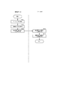
図4を参照して、本発明の実施形態における、撮像処理の概要について説明する。図4は、本発明の実施形態における、撮像処理の概要を示すフローチャートである。以下、説明する処理は、撮像装置100のCPU201が、撮像装置100のRAM202をワークエリアとして、外部メモリ213に格納された本発明のプログラムを実行することにより実現される。
With reference to FIG. 4, the outline of the imaging process in the embodiment of the present invention will be described. FIG. 4 is a flowchart showing an outline of the imaging process in the embodiment of the present invention. The processing described below is realized by the
撮像装置100のCPU201は、ユーザからの指示を受け付け、不図示のメニュー画面を表示画面に表示する(ステップS401)。
The
撮像装置100のCPU201は、ユーザからの指示を受け付け(ステップS402)、受け付けた指示が共有撮影の実行指示か否かを判定する(ステップS403)。共有撮影の実行指示とは、例えば、不図示のメニュー画面上に表示された共有撮影モードのアイコンの選択指示であって、撮像装置100のCPU201は、撮像装置100の外部メモリに記憶されたアプリケーションを起動して、後述するステップS404〜S406、及び、図5〜図7に記載の撮像装置100における各種処理を実行するものである。
撮像装置100のCPU201は、受け付けた指示が共有撮影の実行指示であると判定した場合(ステップS403でYES)、処理をステップS404に移行し、位置情報送信処理を実行する(ステップS404)。
The
If the
当該位置情報送信処理とは、他装置(他の撮像装置)に対して、自装置の位置情報を送信し、他装置の表示画面上に、自装置(自装置の表示画面上の位置)に対応するオブジェクトを表示させるための処理である。 The position information transmission process transmits the position information of the own apparatus to another apparatus (another imaging apparatus), and displays the position information on the display screen of the other apparatus. This is a process for displaying the corresponding object.
ここで図5を参照して、本発明の実施形態における、位置情報送信処理の詳細について説明する。本発明の実施形態における、位置情報送信処理の詳細を示すフローチャートである。 Here, with reference to FIG. 5, the details of the position information transmission processing in the embodiment of the present invention will be described. It is a flowchart which shows the detail of the positional infomation transmission process in embodiment of this invention.
撮像装置100のCPU201は、撮像処理(ライブビュー映像/ライブ画像データの取得処理)を実行して画像データを取得し(ステップS501)、また、自装置の位置情報、方位情報を取得して(ステップS502)、当該画像データ及び、位置情報、方位情報を、撮像装置100の識別情報(例えばIPアドレス)と共にサーバ200に送信する(ステップS503/画像データ送信手段)。以下、当該撮像装置の識別情報、画像データ、位置情報、方位情報をまとめて撮像装置情報とする。
The
サーバ200のCPU201は、当該撮像装置情報を受信し(ステップS504)、外部メモリの所定に記憶領域に、サーバ内撮影装置情報として記憶して(ステップS505)、処理を終了する。以上が図5の、本発明の実施形態における、位置情報送信処理の詳細についての説明である。
The
ここで図9を参照して、本発明の実施形態における、撮像装置情報データテーブル構成の一例について説明する。図9は、本発明の実施形態における、撮像装置情報データテーブル構成の一例を示す図である。 Here, with reference to FIG. 9, an example of the configuration of the imaging device information data table in the embodiment of the present invention will be described. FIG. 9 is a diagram illustrating an example of the configuration of the imaging device information data table in the embodiment of the present invention.
自撮像装置情報900は、図5のステップS503で、撮像装置100がサーバ200に送信した、撮像装置100の撮像装置情報である。
The image capturing apparatus information 900 is image capturing apparatus information of the
サーバ内撮像装置情報910は、サーバ200のCPU201が、複数の撮像装置から受信して外部メモリに記憶した、各撮像装置100の撮像装置情報である。
The in-server imaging device information 910 is imaging device information of each
他撮像装置情報920は、後述する図6のステップS605で、サーバ200から撮像装置100に送信される、撮像装置100の位置から所定の範囲内の位置情報を有する撮像装置情報(そのリスト)である。
The other imaging device information 920 is imaging device information (its list) having position information within a predetermined range from the position of the
装置IP901は、当該撮像装置情報の送信元である撮像装置の識別情報であるIPアドレスである。サーバ200のCPU201は、当該IPアドレスを用いて、撮像装置情報の送信先の撮像装置100を特定し、当該撮像装置情報を送信する。尚、ここでは、撮像装置情報の識別情報としてIPアドレスを用いたが、当該識別情報は、例えば、各装置に設定されている個別の端末ID等であってもよい。
An
位置情報902は、撮像装置100の位置情報である。方位情報903は、撮像装置100の方位情報である。画像情報904(画像データ904)は、撮像装置100のCPU201が撮像制御部を制御することで継続的に取得しているライブビュー画像の情報である。
The
当該位置情報902、方位情報903、画像情報904は、方向によって随時変更され、継続的にサーバ200に送信されるものである。
The
サーバ内撮像装置情報910の、装置IP911は、撮像装置100の識別情報である。位置情報912、方位情報913、画像情報914は、各装置IPにより識別される撮像装置100より随時受信し、変更、更新される一時データである。
The
他撮像装置情報920の装置IP921は、撮像装置100の識別情報である。位置情報922、方位情報923、画像情報924は、後述する図6のステップS605で、サーバ200から撮像装置100に送信される、撮像装置100の位置から所定の範囲内の位置情報を有する他の撮像装置の撮像装置情報(そのリスト)である。以上が図9の、本発明の実施形態における、撮像装置情報データテーブル構成の一例についての説明である。
The
図4の説明に戻る。撮像装置100のCPU201は、ステップS405で撮像処理を実行する(ステップS405)。
Returning to the description of FIG. The
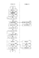
ここで図6を参照して、本発明の実施形態における、撮像処理の詳細について説明する。図6は、本発明の実施形態における、撮像処理の詳細を示すフローチャートである。 Here, with reference to FIG. 6, the details of the imaging process in the embodiment of the present invention will be described. FIG. 6 is a flowchart showing details of the imaging process in the embodiment of the present invention.
撮像装置100のCPU201は、ライブビューの画像データを表示する撮像画面を表示し(ステップS601)、当該撮像装置100の周辺に位置する他の撮像装置の位置情報をサーバ200に要求する(ステップS602/取得要求)。
The
サーバ200のCPU201は当該要求を受信し(ステップS603)、当該要求の送信元の撮像装置100(例えば、装置IP=192.168.1.111)の位置情報と、サーバ内撮像装置情報910の位置情報位置情報を比較して、当該撮像装置100の位置から所定の範囲内の位置情報910を有する撮像装置情報を取得して(ステップS604)、他撮像装置情報920に挿入し、撮像装置100に送信する(ステップS605)。
The
撮像装置100のCPU201は、位置情報を含む当該他撮像装置情報920を受信し(ステップS606)、取得した位置情報と、自装置の位置情報と、自装置の方位情報(撮影可能な画角の情報を含む)とを用いて、当該画角に含まれる他の撮像装置(撮像装置の位置情報/緯度・経度の情報)を特定し、当該表示画面上の当該他の撮像装置の位置に、当該他の撮像装置に対応するアイコン(オブジェクト/エアタグ)を表示する(ステップS607)。
The
尚、ここでは、撮像装置100において、表示画面画面上に表示される(画角に含まれる)位置情報、当該位置情報の示す他の撮像装置を特定して、当該特定した撮像装置に対応するアイコンを当該表示画面上の前記他の撮像装置の位置に配置するものとしたが、例えば、サーバ200のCPU201が、サーバ内撮像装置情報910の各情報を用いて、撮像装置100の画角に含まれる位置情報(他の撮像装置)を特定し、当該位置情報を撮像装置100に送信して、撮像装置100のCPU201は、受信した位置情報を用いて、前記他の撮像装置に対応するアイコンを当該表示画面上の前記他の撮像装置の位置に配置するようにしてもよい。
Here, in the
尚、位置情報に基づいてアイコンを表示画面上へ配置して表示する技術は、従来のエアタグ等の配置処理に知られるものであり、既存の技術であるため、ここでは説明を割愛する。当該配置処理の技術については、例えば、セカイカメラ(商標)の技術や、引用文献/特許第4993637号公報において開示されている。 Note that the technique for arranging and displaying icons on the display screen based on the position information is known in the conventional arrangement process for air tags and the like, and is an existing technique, and therefore the description thereof is omitted here. The arrangement processing technique is disclosed, for example, in the technique of Sekai Camera (trademark) and cited document / patent No. 4999337.
ここで図10を参照して、本発明の実施形態における、被写体と撮像装置、撮像装置同士の位置関係について説明する。図10は、本発明の実施形態における、被写体と撮像装置、撮像装置同士の位置関係を示す図である。 Here, with reference to FIG. 10, the positional relationship between the subject, the imaging device, and the imaging devices in the embodiment of the present invention will be described. FIG. 10 is a diagram illustrating a positional relationship between the subject, the imaging device, and the imaging devices in the embodiment of the present invention.
以下、撮像装置100を、他の撮像装置(撮像装置100B)のライブビュー画像を受信して表示する、被写体の側面に位置する撮像装置100Aと、被写体の正面に位置する、ライブビュー画像の送信元の撮像装置100Bに分けて説明する。
Hereinafter, the
被写体1000は、撮像装置100A、100Bにより撮像されている。当該撮像装置100A、撮像装置100Bは、例えば、それぞれ別のユーザが使用しているものである。表示画像1001は、撮像装置100Aの表示画面に表示されているライブビューであり、表示画像1002は、撮像装置100Bの表示画面に表示されているライブビューである。撮像方向1004は、各撮像装置の撮像している方向を示す。
The subject 1000 is imaged by the
本発明の第1の実施形態においては、図10に示すように、撮像装置100Aの撮像方向1005(焦点位置/焦点の方向)が撮像装置100Bに向いた場合は、撮像装置100Aの表示画面の画像を、撮像装置100Bの表示画面の画像と同じ、例えば被写体の正面の画像に切り替える。
In the first embodiment of the present invention, as shown in FIG. 10, when the imaging direction 1005 (focus position / focus direction) of the
当該画像データは撮像装置100Bから、サーバ200を介して撮像装置100Aに送信される。以上が図10の、本発明の実施形態における、被写体と撮像装置、撮像装置同士の位置関係についての説明である。
The image data is transmitted from the
ここで図11を参照して、本発明の実施形態における、撮像画面の構成、及び遷移の様子の一例について説明する。図11は、本発明の実施形態における、撮像画面の構成、及び遷移の様子の一例を示す図である。 Here, with reference to FIG. 11, an example of a configuration of an imaging screen and a transition state in the embodiment of the present invention will be described. FIG. 11 is a diagram illustrating an example of a configuration of an imaging screen and a transition state in the embodiment of the present invention.
表示画面1100、表示画面1110の画像は撮像装置100Aの撮像機能を用いて表示するライブビュー映像である。表示画面1120の画像は、撮像装置100B(サーバ200)から取得したライブビュー映像を表示する表示画面である。被写体1101、被写体1111、被写体1121は、撮像対象の被写体である。
The images on the
焦点位置1102(焦点位置表示手段)は、撮像装置100Aの焦点位置(焦点の方向)を示すマーカである。アイコン1103は、撮像装置100Bに対応する、撮像装置100Bの撮像する映像をサーバ200に要求するために用いるアイコンである。当該アイコンは、例えば、サーバ200から受信する撮像装置100Bの位置情報に応じて、撮像装置100Aの表示画面上の、撮像装置100Bと重なる位置に配置され、表示される。
The focal position 1102 (focal position display means) is a marker indicating the focal position (focus direction) of the
焦点位置が、例えばユーザが撮像装置100Aのレンズの方向を移動することにより、焦点位置1112及びアイコン1113に示すように、表示画面上のアイコンに重なる位置に移動した場合、撮像装置100AのCPU201は、サーバ200に撮像装置100Bの画像データを要求し、当該画像データをサーバ200より受信して、他撮像装置画像表示領域1114(画像データ表示領域)に表示する。
When the focus position is moved to a position overlapping the icon on the display screen as indicated by the
また、当該他撮像装置画像表示領域1114に対する拡大表示指示(例えば、ダブルタップ操作)を受け付けた場合に、表示画面1120に示すように、当該他撮像装置画像表示領域1114に表示中の画像を拡大して全画面表示する。
Further, when an enlargement display instruction (for example, a double tap operation) for the other imaging device
また、当該他撮像装置画像表示領域1114、又は、表示画面1120に対する撮像指示(例えば、タップ操作)を受け付けた場合に、当該タップ操作を受け付けた時点での画像データをキャプチャ(撮像)して、撮像装置100Aに接続されたメモリカードに記憶する。
Further, when an imaging instruction (for example, a tap operation) is received with respect to the other imaging device
尚、ここでは撮像指示の操作方法の一例としてタップ操作を挙げたが、例えば、撮像装置100に設置された不図示のシャッターボタンの押下指示であってもよい。
Here, the tap operation is described as an example of the operation method of the imaging instruction. However, for example, an instruction to press a shutter button (not illustrated) installed in the
また、ここでは、各アイコンを、単に撮像装置の位置を示す情報として表示しているが、例えば、方位情報923を用いて、当該撮像装置の向いている方位、方向を示す矢印をアイコンとして表示画面に表示するようしにてもよい。こうすることで、ユーザは自らの各アイコンの示す撮像装置が、自分の所望する画角を含むものかを容易に認識できる。以上が図11の、本発明の実施形態における、撮像画面の構成、及び遷移の様子の一例についての説明である。
Here, each icon is simply displayed as information indicating the position of the imaging device. For example, using the
図6の説明に戻る。撮像装置100のCPU201は、撮像装置100の焦点位置(撮像装置100の表示画面上に表示された焦点位置を示すマーカ)と、撮像装置100の表示画面上に表示された、他の撮像装置と対応するアイコンと、が重なったか否かを判定し(ステップS608)、重なっていないと判定した場合は(ステップS608でNO)、処理をステップS608の前に戻す。
Returning to the description of FIG. The
重なったと判定した場合は(ステップS608でYES)、処理をステップS609に移行し、当該アイコンに対応する撮像装置が撮像中の画像データをサーバ200に要求する(ステップS609)。 If it is determined that they overlap (YES in step S608), the process proceeds to step S609, and the imaging apparatus corresponding to the icon requests the server 200 for image data being captured (step S609).
サーバ200のCPU201は、当該要求を受信し(ステップS610)、当該画像データを記憶領域から取得して、撮像装置100に返送する(ステップS611)。撮像装置100のCPU201は、当該画像データを受信して(ステップS612)、ライブビュー映像として、表示画面上の特定の領域(例えば、図11の、他撮像装置画像表示領域1114)に表示する(ステップS613)。
The
撮像装置100のCPU201は、当該他の撮像装置で撮影中の画像データを、拡大表示する指示を受け付けたか否かを判定し(ステップS614)、拡大表示する指示を受け付けたと判定した場合(ステップS614でYES)、当該画像データを拡大表示して(ステップS615/図11の表示画面1120)、処理をステップS616に移行する。拡大表示する指示を受け付けていないと判定した場合(ステップS614でNO)、拡大表示を行わず、処理をステップS616に移行する。
The
サーバ200のCPU201は、他の撮像装置で撮像中の画像の撮像指示を受け付けたか否かを判定する(ステップS616)。つまり、図11でいう、他撮像装置画像表示領域1114、又は表示画面1120に対するタップ指示を受け付けたか否かを判定する。撮像指示を受け付けていないと判定した場合(ステップS616でNO)、処理を終了する。
The
尚、他撮像装置画像表示領域1114、又は表示画面1120ではない、撮像装置100Aが撮像中のライブビュー映像を表示している表示領域に対する撮像指示(タップ指示)を受け付けた場合、当該撮像装置100Aが撮像中の画像データを静止画として撮影し、記憶領域に記憶するものとする。
When an imaging instruction (tap instruction) is received for a display area in which the
撮像指示を受け付けたと判定した場合(ステップS616でYES)、当該他撮像装置画像表示領域1114、又は表示画面1120に表示されている画像データ(他の撮像装置/撮像装置100Bで撮像中の画像データ)を撮像(キャプチャ)して取得するする(ステップS617)。
If it is determined that the imaging instruction has been received (YES in step S616), the image data displayed on the other imaging device
サーバ200のCPU201は、ステップS617で取得した画像データを、撮像装置100に接続されたメモリカードに記憶して(ステップS618)、処理を終了する。以上が図6の、本発明の実施形態における、撮像処理の詳細についての説明である。
The
図4の説明に戻る。撮像装置100のCPU201は、ステップS403で指示を受け付けることにより開始した、共有撮影処理の終了指示を受け付けたか否かを判定する(ステップS406)。例えば、図10の表示画面1100上に表示される、不図示の共有撮影モード終了のためのボタンの押下指示を受け付けた場合、共有撮影処理の終了指示を受け付けたと判定する。
Returning to the description of FIG. The
共有撮影処理の終了指示を受け付けたと判定した場合(ステップS406でYES)、共有撮影モードを終了し、処理を終了する。共有撮影処理の終了指示を受け付けていないと判定した場合(ステップS406でNO)、処理をステップS403の前に戻す。以上が図4の、本発明の実施形態における、撮像処理の概要についての説明である。 If it is determined that an instruction to end the shared shooting process has been received (YES in step S406), the shared shooting mode is ended and the process ends. If it is determined that an instruction to end the shared shooting process has not been received (NO in step S406), the process returns to step S403. The above is the description of the outline of the imaging process in the embodiment of the present invention shown in FIG.
以上、本発明の第1の実施形態について説明した。次に、図4、図7、図8、図12を参照して、本発明の第2の実施形態について説明する。本発明の第2の実施形態においては、撮像装置100(例えば撮像装置100B)が当該撮像装置100の位置情報、方位情報、画像データをブロードキャストで発信し、他の撮像装置(例えば撮像装置100A)が、当該ブロードキャスト発信された各情報を受信する。つまり、ブロードキャストで発信された情報を受信可能な範囲にある、自機周辺に存在する撮像装置100を検索して特定する。
The first embodiment of the present invention has been described above. Next, a second embodiment of the present invention will be described with reference to FIG. 4, FIG. 7, FIG. 8, and FIG. In the second embodiment of the present invention, the imaging device 100 (for example, the
他の撮像装置(撮像装置100A)は、当該受信した位置情報を基に、表示画面上に撮像装置100Bに対応するオブジェクト(アイコン)を表示し、当該オブジェクトが選択された場合に、撮像装置100Bの撮像中の画像データを、撮像装置Bより直接取得して表示画面に表示する処理を行う。
The other imaging device (
図4の処理については、本発明の第1の実施形態の説明にて前述したため、ここでは説明を割愛し、ステップS404の詳細を示す図7、及び、ステップS405の詳細を示す図8について説明する。図7を参照して、本発明の実施形態における、位置情報送信処理の詳細について説明する。図7は、本発明の実施形態における、位置情報送信処理の詳細を示すフローチャートである。 Since the processing of FIG. 4 has been described in the description of the first embodiment of the present invention, description thereof is omitted here, and FIG. 7 showing details of step S404 and FIG. 8 showing details of step S405 are explained. To do. With reference to FIG. 7, the details of the position information transmission processing in the embodiment of the present invention will be described. FIG. 7 is a flowchart showing details of position information transmission processing in the embodiment of the present invention.
撮像装置100のCPU201は、撮像装置100に搭載された不図示のGPS装置の位置検出機能、加速度センサの機能を用いて、撮像装置100の位置情報、方位情報を取得し(ステップS701)、ブロードキャスト形式で不特定の外部装置(他の撮像装置)に対して発信、送信する(ステップS702)。例えば、図9の自撮像装置情報900の内、画像情報904を除く情報を送信する。以上が図7の、本発明の実施形態における、位置情報送信処理の詳細についての説明である。
The
次に図8を参照して、本発明の実施形態における、撮像処理の詳細について説明する。図8は、本発明の実施形態における、撮像処理の詳細を示すフローチャートである。 Next, with reference to FIG. 8, the details of the imaging process in the embodiment of the present invention will be described. FIG. 8 is a flowchart showing details of the imaging processing in the embodiment of the present invention.
以下、撮像装置100を、他の撮像装置(撮像装置100B)のライブビュー画像を受信して表示する、被写体の側面に位置する撮像装置100Aと、被写体の正面に位置する、ライブビュー画像の送信元の撮像装置100Bに分けて説明する。
Hereinafter, the
撮像装置100のCPU201は、ライブビューの画像データを表示する撮像画面を表示し(ステップS801)、ブロードキャスト送信されている、周辺の撮像装置の位置情報、方位情報、当該情報の送信元の撮像装置の装置IPを取得する(ステップS802/識別情報取得手段)。
The
撮像装置100のCPU201は、取得した位置情報と、自装置の位置情報及び方位情報とを用いて、表示画面上の他の撮像装置の位置を特定し、当該他の撮像装置の位置に、当該他の撮像装置に対応するアイコン(オブジェクト)を表示する(ステップS803)。
尚、当該アイコンの表示画面上への配置処理は、従来のエアタグ等の配置処理に知られるものであり、既存の技術であるため、ここでは説明を割愛する。
The
In addition, since the arrangement | positioning process on the display screen of the said icon is known by the arrangement | positioning processes of the conventional air tag etc., and is an existing technique, description is omitted here.
ここで図12を参照して、本発明の実施形態における、撮像画面の構成、及び遷移の様子の一例について説明する。図12は、本発明の実施形態における、撮像画面の構成、及び遷移の様子の一例を示す図である。 Here, with reference to FIG. 12, an example of a configuration of an imaging screen and a transition state in the embodiment of the present invention will be described. FIG. 12 is a diagram illustrating an example of a configuration of an imaging screen and a transition state in the embodiment of the present invention.
表示画面1200、表示画面1210の画像は撮像装置100Aの撮像機能を用いて表示するライブビュー映像である。表示画面1220の画像は、撮像装置100Bから取得したライブビュー映像を表示する表示画面である。被写体1201、被写体1211、被写体1221は、撮像対象の被写体である。
The images on the
アイコン1202は、アイコン1212は、撮像装置100Bに対応する、撮像装置100Bの撮像する映像を撮像装置100Bに要求するために用いるアイコンである。当該アイコンは、例えば、撮像装置100Bから受信した撮像装置100Bの位置情報に応じて、撮像装置100Aの表示画面上の、撮像装置100Bと重なる位置に配置され、表示される。また、アイコン1203、アイコン1213は、不図示の撮像装置100Cに対応するアイコンである。
The
表示画面上の各種アイコンの選択指示(例えば、タップ操作)を受け付けた場合、撮像装置100AのCPU201は、当該アイコンに対応する撮像装置の装置IPを特定し、当該装置IPを有する撮像装置に対し、撮像中の画像データを要求し、当該画像データを受信して、選択中のアイコンに対応する撮像装置で撮像中の画像データ(ライブビュー映像)を他撮像装置画像表示領域1214(画像データ表示領域)に表示する。
When an instruction to select various icons on the display screen (for example, a tap operation) is received, the
尚、選択中のアイコンについては、アイコン1213のように、アイコンの色を変えて、未選択のアイコンと識別可能に表示するものとする。当該色の変更処理は、撮像装置に記憶されたアプリケーションが実行する。
Note that the currently selected icon is displayed so that it can be distinguished from an unselected icon by changing the color of the icon, like an
また、ステップS802で取得した方位情報を用いて、自装置の方位情報の示す方位と所定の値より近い方位を示す方位情報を特定し、当該特定された方位情報を有する撮像装置に対応するアイコンと、それ以外の撮像装置に対応するアイコンとを、識別可能に(例えば色を変えて)、表示画面に表示する。当該所定の値の情報は、撮像装置の記憶領域に予め記憶されているものとする。 Further, using the azimuth information acquired in step S802, the azimuth information indicating the azimuth indicated by the azimuth information of the device itself and the azimuth closer than a predetermined value is specified, and the icon corresponding to the imaging device having the specified azimuth information is identified. And icons corresponding to the other imaging devices are displayed on the display screen in a distinguishable manner (for example, by changing the color). It is assumed that the predetermined value information is stored in advance in the storage area of the imaging apparatus.
尚、ここでは、自装置の方位に近い方位の方位情報を有する撮像装置に対応するアイコンと、そうでないアイコンとを識別表示するようにしたが、例えば、自装置の方位に近い方位の方位情報を有する撮像装置に対応するアイコンとを表示画面に表示しないようにしてもよい。 Here, the icon corresponding to the imaging device having the orientation information close to the orientation of the own device and the icon that is not so are identified and displayed. For example, the orientation information of the orientation close to the orientation of the own device The icon corresponding to the image pickup apparatus having may not be displayed on the display screen.
また、ここでは、撮像装置100Aの撮像中のライブビュー映像の中に、周辺の各撮像装置の位置情報に応じてアイコンを配置しているため、撮像装置100Aの撮像中の画角に含まれない撮像装置のアイコンは、表示画面に表示していないが、例えば、当該画角に含まれない位置情報に対応する撮像装置を特定し(画角外位置情報特定手段)、当該撮像装置のリストを、表示画面中の特定の領域にリスト表示し、当該リストの中の撮像装置の選択を受け付けることにより、当該選択を受け付けた撮像装置の撮像中のライブビュー映像を取得し、他撮像装置画像表示領域1214に表示するようにしてもよい。
Here, since the icons are arranged in the live view video being imaged by the
当該他撮像装置画像表示領域1214に対する拡大表示指示(例えば、ダブルタップ操作)を受け付けた場合に、表示画面1220に示すように、当該他撮像装置画像表示領域1214に表示中の画像を拡大して全画面表示する。
When an enlargement display instruction (for example, a double tap operation) is received for the other imaging device
また、当該他撮像装置画像表示領域1214、又は、表示画面1220に対する撮像指示(例えば、タップ操作)を受け付けた場合に、当該撮像指示を撮像装置100Bに送信し、当該撮像指示に応じて撮像装置100Bが撮像した画像データ(例えば静止画像)を、撮像装置100Aに送信し、撮像装置100AのCPU201は、当該画像データを受信してメモリカード等の記憶領域に記憶する。以上が図12の、本発明の実施形態における、撮像画面の構成、及び遷移の様子の一例についての説明である。
Further, when an imaging instruction (for example, a tap operation) for the other imaging apparatus
図8の説明に戻る。撮像装置100のCPU201は、表示画面上に表示されたアイコン(例えば、図12のアイコン1212、アイコン1213)の選択指示(例えば、タップ操作)を受け付けたか否かを判定する(ステップS804)。当該アイコンの選択指示を受け付けていないと判定した場合(ステップS804でNO)、処理をステップS804の前に戻す。
Returning to the description of FIG. The
当該アイコンの選択指示を受け付けたと判定した場合(ステップS804でYES)、当該アイコンに対応する撮像装置が撮像中の画像データを、ステップS802で取得した装置IP901の示す撮像装置(例えば、撮像装置100B)に要求する(ステップS805)。当該要求には、撮像装置100Aの装置IP(装置IP901/IPアドレス)を含めるものとする。
If it is determined that an instruction to select the icon has been received (YES in step S804), the image pickup apparatus (for example, the
撮像装置100BのCPU201は、当該要求を受信し(ステップS806)、撮像中の画像データを、当該要求に含まれるIPアドレスから特定される撮像装置100Aに送信する(ステップS807)。
The
撮像装置100AのCPU201は、当該画像データを受信して(ステップS808)、ライブビュー映像として、表示画面上の特定の領域(例えば、図12の、他撮像装置画像表示領域1214)に表示する(ステップS809)。
The
撮像装置100のCPU201は、当該他の撮像装置で撮影中の画像データを、拡大表示する指示を受け付けたか否かを判定し(ステップS810)、拡大表示する指示を受け付けたと判定した場合(ステップS810でYES)、当該画像データを拡大表示して(ステップS811/図12の表示画面1220)、処理をステップS812に移行する。拡大表示する指示を受け付けていないと判定した場合(ステップS810でNO)、拡大表示を行わず、処理をステップS812に移行する。
The
サーバ200のCPU201は、他の撮像装置で撮像中の画像の撮像指示を受け付けたか否かを判定する(ステップS812)。つまり、図12でいう、他撮像装置画像表示領域1214、又は表示画面1220に対するタップ指示を受け付けたか否かを判定する。撮像指示を受け付けていないと判定した場合(ステップS812でNO)、処理を終了する。
The
撮像指示を受け付けたと判定した場合(ステップS812でYES)、当該他撮像装置画像表示領域1214、又は表示画面1220に表示されている画像データ(他の撮像装置/撮像装置100Bで撮像中の画像データ)の撮像要求を、撮像装置100B(画像データの取得元の撮像装置)に送信する(ステップS813)。尚、当該撮像要求には、当該撮像要求に応じて撮像された画像データを、撮像装置100Bの記憶領域(例えば、撮像装置100Bに接続されているメモリカード)に記憶することなく、撮像装置100Aに送信させる指示を含めるものとする(非記憶指示送信手段)。
If it is determined that the imaging instruction has been received (YES in step S812), the image data displayed on the other imaging device
撮像装置100BのCPU201は、当該要求を受信し(ステップS814)、当該要求に応じて撮像処理(ここでは静止画の撮影処理/シャッターを切る処理、とする)を実行し(ステップS815)、当該撮像した画像データを、撮像装置100Bの記憶領域(例えば、撮像装置100Bに接続されているメモリカード)に記憶することなく、撮像装置100Aに送信する(ステップS816)。
The
こうすることで、撮像装置100Bの記憶領域(例えば、撮像装置100Bに接続されたメモリカード)に、撮像装置100Bのユーザの意図しない画像データが記憶されることを防止する。
By doing so, it is possible to prevent image data not intended by the user of the
撮像装置100AのCPU201は、当該画像データを受信し(ステップS817)、撮像装置100Aに接続されているメモリカード等の記憶領域に記憶する(ステップS818)。以上が図8の、本発明の実施形態における、撮像処理の詳細についての説明である。以上、本発明の第2の実施形態について説明した
The
以上説明したように、本発明によれば、撮像装置の位置情報を用いて、ユーザの所望する他の撮像装置の撮像する画像を取得することが出来る撮像装置、情報処理システム、その制御方法及びプログラムを提供することができる。 As described above, according to the present invention, an image pickup apparatus, an information processing system, a control method thereof, and an image pickup apparatus that can acquire an image picked up by another image pickup apparatus desired by the user using position information of the image pickup apparatus. A program can be provided.
尚、本発明の各実施形態の説明においては、静止画像を撮像し、記憶する処理について説明したが、例えば、動画像を撮像し、記憶するようにしてもよい。この場合、撮像装置100のCPU201は、例えば、他撮像装置画像表示領域に対する1度目のタップ指示を受け付けた場合に、当該他撮像装置画像表示領域に表示された画像データの録画(記憶)を開始し、2度目のタップ指示を受け付けた場合に、画像データの録画を終了する。
In the description of each embodiment of the present invention, the process of capturing and storing a still image has been described. However, for example, a moving image may be captured and stored. In this case, for example, when the
また、前述した実施形態の機能を実現するプログラムを記録した記録媒体を、システムあるいは装置に供給し、そのシステムあるいは装置のコンピュータ(またはCPUやMPU)が記録媒体に格納されたプログラムを読出し実行することによっても、本発明の目的が達成されることは言うまでもない。 Also, a recording medium that records a program that realizes the functions of the above-described embodiments is supplied to a system or apparatus, and a computer (or CPU or MPU) of the system or apparatus reads and executes the program stored in the recording medium. It goes without saying that the object of the present invention can also be achieved.
この場合、記録媒体から読み出されたプログラム自体が本発明の新規な機能を実現することになり、そのプログラムを記憶した記録媒体は本発明を構成することになる。 In this case, the program itself read from the recording medium realizes the novel function of the present invention, and the recording medium storing the program constitutes the present invention.
プログラムを供給するための記録媒体としては、例えば、フレキシブルディスク,ハードディスク,光ディスク,光磁気ディスク,CD−ROM,CD−R,DVD−ROM,磁気テープ,不揮発性のメモリカード,ROM,EEPROM,シリコンディスク等を用いることができる。 As a recording medium for supplying the program, for example, a flexible disk, hard disk, optical disk, magneto-optical disk, CD-ROM, CD-R, DVD-ROM, magnetic tape, nonvolatile memory card, ROM, EEPROM, silicon A disk or the like can be used.
また、各装置が読み出したプログラムを実行することにより、前述した実施形態の機能が実現されるだけでなく、そのプログラムの指示に基づき、コンピュータ上で稼働しているOS(オペレーティングシステム)等が実際の処理の一部または全部を行い、その処理によって前述した実施形態の機能が実現される場合も含まれることは言うまでもない。 Further, by executing the program read by each device, not only the functions of the above-described embodiments are realized, but also an OS (operating system) running on the computer is actually executed based on the instructions of the program. It goes without saying that a case where the function of the above-described embodiment is realized by performing a part or all of the process and the process is included.
さらに、記録媒体から読み出されたプログラムが、コンピュータに挿入された機能拡張ボードやコンピュータに接続された機能拡張ユニットに備わるメモリに書き込まれた後、そのプログラムコードの指示に基づき、その機能拡張ボードや機能拡張ユニットに備わるCPU等が実際の処理の一部または全部を行い、その処理によって前述した実施形態の機能が実現される場合も含まれることは言うまでもない。 Furthermore, after the program read from the recording medium is written to the memory provided in the function expansion board inserted into the computer or the function expansion unit connected to the computer, the function expansion board is based on the instructions of the program code. It goes without saying that the case where the CPU or the like provided in the function expansion unit performs part or all of the actual processing and the functions of the above-described embodiments are realized by the processing.
また、本発明は、例えば上述したように、複数の機器から構成されるシステムに適用しても、1つの機器からなる装置に適用してもよい。また、本発明は、システムあるいは装置にプログラムを供給することによって達成される場合にも適応できることは言うまでもない。この場合、本発明を達成するためのプログラムを格納した記録媒体を該システムあるいは装置に読み出すことによって、そのシステムあるいは装置が、本発明の効果を享受することが可能となる。 Further, for example, as described above, the present invention may be applied to a system including a plurality of devices or an apparatus including a single device. Needless to say, the present invention can be applied to a case where the present invention is achieved by supplying a program to a system or apparatus. In this case, by reading a recording medium storing a program for achieving the present invention into the system or apparatus, the system or apparatus can enjoy the effects of the present invention.
さらに、本発明を達成するためのプログラムをネットワーク上のサーバ,データベース等から通信プログラムによりダウンロードして読み出すことによって、そのシステムあるいは装置が、本発明の効果を享受することが可能となる。 Furthermore, by downloading and reading a program for achieving the present invention from a server, database, etc. on a network by a communication program, the system or apparatus can enjoy the effects of the present invention.
なお、上述した各実施形態およびその変形例を組み合わせた構成も全て本発明に含まれるものである。 In addition, all the structures which combined each embodiment mentioned above and its modification are also included in this invention.
また上記のソフトウェアで実現する各処理を、ファームウェアやハードウェア構成にして、各処理を各手段として実現することも可能であり、本発明の技術的範囲はこのようなファームウェアやハードウェア構成による実現も含むものである。 In addition, each process realized by the above-described software can be realized as firmware or hardware configuration, and each process can be realized as each means. The technical scope of the present invention is realized by such firmware or hardware configuration. Is also included.
100A 撮像装置
100B 撮像装置
200 サーバ
101 WAN
201 CPU
202 RAM
203 ROM
204 システムバス
205 入力コントローラ
206 ビデオコントローラ
207 メモリコントローラ
208 通信/IFコントローラ
209 撮像装置
210 タッチパネル
211 CRT
212 音声再生装置
213 外部メモリ
999 ネットワーク
201 CPU
202 RAM
203 ROM
204
212
Claims (17)
前記撮像装置により撮像された他の撮像装置を、自機の位置及び方向と当該他の撮像装置の位置を用いて特定する特定手段と、
前記特定手段により特定された他の撮像装置を選択する選択手段と、
前記選択手段で選択された前記他の撮像装置によって撮像された撮像画像を記憶装置より取得する取得手段と、
前記取得手段で取得した前記撮像画像を表示画面に表示する画像表示手段と、
自機で制御する撮像装置の焦点位置を表示画面に表示する焦点位置表示手段と、
を備え、
前記選択手段は、前記焦点位置表示手段で表示された焦点位置と、表示画面上の前記他の撮像装置が重なった場合に、前記他の撮像装置の選択をすることを特徴とする情報処理装置。 An information processing apparatus having a display screen for controlling an imaging device,
Identifying means for identifying another imaging device imaged by the imaging device using the position and direction of the own device and the position of the other imaging device;
Selecting means for selecting another imaging device identified by the identifying means;
Acquisition means for acquiring a captured image captured by the other imaging apparatus selected by the selection means from a storage device;
Image display means for displaying the captured image acquired by the acquisition means on a display screen;
A focal position display means for displaying on the display screen the focal position of the imaging device controlled by the own device;
With
The information processing apparatus , wherein the selection unit selects the other imaging device when the focal position displayed by the focal position display unit overlaps the other imaging device on the display screen. .
を備え、
前記選択手段は、前記オブジェクト表示手段で表示されたオブジェクトの選択を受け付けることで、選択を受け付けたオブジェクトに対応する前記識別情報の前記他の撮像装置を特定し、
前記取得手段は、選択を受け付けたオブジェクトに対応する前記識別情報に基づいて、前記特定手段により特定された前記他の撮像装置によって撮像された撮像画像を記憶装置より取得することを特徴とする請求項1に記載の情報処理装置。 An object corresponding to the identification information of the other imaging device for displaying the captured image captured by the other imaging device specified by the specifying unit on the display screen is displayed on the display screen in a selectable manner. Object display means;
With
The selection unit identifies the other imaging device of the identification information corresponding to the object that has received the selection by receiving the selection of the object displayed by the object display unit,
Said acquisition means, based on the identification information corresponding to the accepted selection object, and acquires from the storage device a captured image captured by the other imaging apparatus specified by the specifying means The information processing apparatus according to claim 1.
前記撮像装置により撮像された他の撮像装置を、自機の位置及び方向と当該他の撮像装置の位置を用いて特定する特定手段と、Identifying means for identifying another imaging device imaged by the imaging device using the position and direction of the own device and the position of the other imaging device;
前記特定手段により特定された他の撮像装置を選択する選択手段と、Selecting means for selecting another imaging device identified by the identifying means;
前記選択手段で選択された前記他の撮像装置によって撮像された撮像画像を記憶装置より取得する取得手段と、Acquisition means for acquiring a captured image captured by the other imaging apparatus selected by the selection means from a storage device;
前記取得手段で取得した前記撮像画像を表示画面に表示する画像表示手段と、Image display means for displaying the captured image acquired by the acquisition means on a display screen;
前記特定手段により特定された他の撮像装置によって撮像される撮像画像を前記表示画面に表示するための当該他の撮像装置の識別情報に対応するオブジェクトを、前記表示画面上に選択可能に表示するオブジェクト表示手段と、An object corresponding to the identification information of the other imaging device for displaying the captured image captured by the other imaging device specified by the specifying unit on the display screen is displayed on the display screen in a selectable manner. Object display means;
を備え、With
前記オブジェクト表示手段は、自機の方向の情報と前記他の撮像装置の方向の情報とを用いて、自機の方向に対して所定の値より遠い方向を示す前記他の撮像装置の撮像画像を表示するためのオブジェクトを認識可能に表示し、The object display means uses the information on the direction of the own device and the information on the direction of the other imaging device to capture a captured image of the other imaging device that indicates a direction farther than a predetermined value with respect to the direction of the own device. Recognizable object for displaying
前記選択手段は、前記オブジェクト表示手段で表示されたオブジェクトの選択を受け付けることで、選択を受け付けたオブジェクトに対応する前記識別情報の前記他の撮像装置を特定し、The selection unit identifies the other imaging device of the identification information corresponding to the object that has received the selection by receiving the selection of the object displayed by the object display unit,
前記取得手段は、選択を受け付けたオブジェクトに対応する前記識別情報に基づいて、前記特定手段により特定された前記他の撮像装置によって撮像された撮像画像を記憶装置より取得することを特徴とする情報処理装置。The acquisition unit acquires, from a storage device, a captured image captured by the other imaging device specified by the specifying unit, based on the identification information corresponding to the object that has received a selection. Processing equipment.
前記特定手段は、自機の撮像装置の画角に含まれる他の撮像装置を特定し、
前記オブジェクト表示手段は、前記特定手段により特定された自機の撮像装置によって撮像される他の撮像装置で撮像された撮像画像を自機の表示画面に表示するためのオブジェクトを表示画面上に選択可能に表示することを特徴とする請求項2又は3に記載の情報処理装置。 The information processing apparatus is an information processing apparatus for displaying a captured image captured by the imaging device included in the own apparatus on a display screen,
The specifying unit specifies the other imaging device that is part of the angle of view of the imaging device of its own,
The object display means selects, on the display screen, an object for displaying on the display screen of the own apparatus an image picked up by another image pickup apparatus picked up by the own image pickup apparatus specified by the specifying means. It can be characterized in that the display information processing apparatus according to claim 2 or 3.
を備えることを特徴とする請求項1乃至5のいずれか1項に記載の情報処理装置。 Storage means for storing the captured image in its own storage device by receiving an imaging instruction for storing the captured image in the storage device;
The information processing apparatus according to any one of claims 1 to 5, characterized in that it comprises.
前記撮像指示は、前記表示画面に対する操作指示であって、
前記記憶手段は、撮像指示を受け付けた位置が自機の撮像装置の撮像画像を表示する第1の領域である場合に、自機の撮像装置で撮像した画像を記憶し、撮像指示を受け付けた位置が、前記取得手段により前記他の撮像装置から取得された撮像画像を前記画像表示手段により表示する第2の領域である場合に、前記他の撮像装置で撮像中の画像データを自機の記憶装置に記憶することを特徴とする請求項6に記載の情報処理装置。 The information processing apparatus includes an imaging device in its own machine,
The imaging instruction is an operation instruction for the display screen,
The storage means stores an image captured by the imaging device of the own device and accepts the imaging instruction when the position where the imaging instruction is received is the first region for displaying the captured image of the imaging device of the own device. When the position is the second area where the image display unit displays the captured image acquired from the other imaging device by the acquisition unit, the image data being captured by the other imaging device The information processing apparatus according to claim 6 , wherein the information processing apparatus is stored in a storage device.
前記撮像装置により撮像された他の撮像装置を、自機の位置及び方向と当該他の撮像装置の位置を用いて特定する特定工程と、
前記特定工程により特定された他の撮像装置を選択する選択工程と、
前記選択工程で選択された前記他の撮像装置によって撮像された撮像画像を記憶装置より取得する取得工程と、
前記取得工程で取得した前記撮像画像を表示画面に表示する画像表示工程と、
自機で制御する撮像装置の焦点位置を表示画面に表示する焦点位置表示工程と、
を含み、
前記選択工程は、前記焦点位置表示工程で表示された焦点位置と、表示画面上の前記他の撮像装置が重なった場合に、前記他の撮像装置の選択をすることを特徴とする情報処理装置の制御方法。 A control method for an information processing apparatus including a display screen for controlling an imaging apparatus,
A specifying step of specifying another imaging device imaged by the imaging device using the position and direction of the own device and the position of the other imaging device;
A selection step of selecting another imaging device identified by the identification step;
An acquisition step of acquiring from a storage device a captured image captured by the other imaging device selected in the selection step;
An image display step for displaying the captured image acquired in the acquisition step on a display screen;
A focal position display step of displaying on the display screen the focal position of the imaging device controlled by the own device;
Including
In the information processing apparatus , the selection step selects the other imaging device when the focal position displayed in the focal position display step overlaps the other imaging device on the display screen. Control method.
前記情報処理装置を、
前記撮像装置により撮像された他の撮像装置を、自機の位置及び方向と当該他の撮像装
置の位置を用いて特定する特定手段と、
前記特定手段により特定された他の撮像装置を選択する選択手段と、
前記選択手段で選択された前記他の撮像装置によって撮像された撮像画像を記憶装置より取得する取得手段と、
前記取得手段で取得した前記撮像画像を表示画面に表示する画像表示手段と
自機で制御する撮像装置の焦点位置を表示画面に表示する焦点位置表示手段として機能させ、
前記選択手段は、前記焦点位置表示手段で表示された焦点位置と、表示画面上の前記他の撮像装置が重なった場合に、前記他の撮像装置の選択をすることを特徴とする情報処理装置のプログラム。 A program that can be executed by an information processing apparatus that includes a display screen and controls an imaging device,
The information processing apparatus;
Identifying means for identifying another imaging device imaged by the imaging device using the position and direction of the own device and the position of the other imaging device;
Selecting means for selecting another imaging device identified by the identifying means;
Acquisition means for acquiring a captured image captured by the other imaging apparatus selected by the selection means from a storage device;
Image display means for displaying the captured image acquired by the acquisition means on a display screen;
It functions as a focal position display means for displaying the focal position of the imaging device controlled by the own device on the display screen,
The information processing apparatus , wherein the selection unit selects the other imaging device when the focal position displayed by the focal position display unit overlaps the other imaging device on the display screen. Program.
前記情報処理装置は、
前記撮像装置により撮像された他の撮像装置を、自機の位置及び方向と当該他の撮像装置の位置を用いて特定する特定手段と、
前記特定手段により特定された他の撮像装置を選択する選択手段と、
前記選択手段で選択された前記他の撮像装置によって撮像された撮像画像を、前記サーバに要求して取得する取得手段と、
前記取得手段で取得した前記撮像画像を表示画面に表示する画像表示手段と、
自機で制御する撮像装置の焦点位置を表示画面に表示する焦点位置表示手段と、
を備え、
前記選択手段は、前記焦点位置表示手段で表示された焦点位置と、表示画面上の前記他の撮像装置が重なった場合に、前記他の撮像装置の選択をし、
前記サーバは、
前記撮像装置からの要求に応じて、前記特定手段によって特定された前記他の撮像装置の撮像画像を、前記情報処理装置に送信する撮像画像送信手段と、
を備えることを特徴とする情報処理システム。 Controlling the imaging device, and an information processing apparatus including a display screen, an information processing system including a server having a storage device for storing images captured by the imaging device,
The information processing apparatus includes:
Identifying means for identifying another imaging device imaged by the imaging device using the position and direction of the own device and the position of the other imaging device;
Selecting means for selecting another imaging device identified by the identifying means;
Obtaining means for requesting and obtaining a captured image captured by the other imaging device selected by the selection means;
Image display means for displaying the captured image acquired by the acquisition means on a display screen;
A focal position display means for displaying on the display screen the focal position of the imaging device controlled by the own device;
With
The selection unit selects the other imaging device when the focal position displayed by the focal position display unit and the other imaging device on the display screen overlap,
The server
In response to a request from the imaging device, a captured image transmission unit that transmits a captured image of the other imaging device specified by the specifying unit to the information processing device;
An information processing system comprising:
前記情報処理装置において、
前記撮像装置により撮像された他の撮像装置を、自機の位置及び方向と当該他の撮像装置の位置を用いて特定する特定工程と、
前記特定工程により特定された他の撮像装置を選択する選択工程と、
前記選択工程で選択された前記他の撮像装置によって撮像された撮像画像を、前記サーバに要求して取得する取得工程と、
前記取得工程で取得した前記撮像画像を表示画面に表示する画像表示工程と、
自機で制御する撮像装置の焦点位置を表示画面に表示する焦点位置表示工程と、
を含み、
前記選択工程は、前記焦点位置表示工程で表示された焦点位置と、表示画面上の前記他の撮像装置が重なった場合に、前記他の撮像装置の選択をし、
前記サーバにおいて、
前記撮像装置からの要求に応じて、前記特定工程によって特定された前記他の撮像装置の撮像画像を、前記情報処理装置に送信する撮像画像送信工程と、
を含むことを特徴とする情報処理システムの制御方法。 Controlling the imaging apparatus, a control method of an information processing system including an information processing apparatus including a display screen, and a server having a storage device for storing images captured by the imaging device,
In the information processing apparatus,
A specifying step of specifying another imaging device imaged by the imaging device using the position and direction of the own device and the position of the other imaging device;
A selection step of selecting another imaging device identified by the identification step;
An acquisition step of requesting and acquiring a captured image captured by the other imaging device selected in the selection step;
An image display step for displaying the captured image acquired in the acquisition step on a display screen;
A focal position display step of displaying on the display screen the focal position of the imaging device controlled by the own device;
Including
The selection step selects the other imaging device when the focal position displayed in the focal position display step and the other imaging device on the display screen overlap,
In the server,
In response to a request from the imaging device, a captured image transmission step of transmitting a captured image of the other imaging device identified by the identifying step to the information processing device;
A method for controlling an information processing system comprising:
前記情報処理装置を、
前記撮像装置により撮像された他の撮像装置を、自機の位置及び方向と当該他の撮像装置の位置を用いて特定する特定手段と、
前記特定手段により特定された他の撮像装置を選択する選択手段と、
前記選択手段で選択された前記他の撮像装置によって撮像された撮像画像を、前記サーバに要求して取得する取得手段と、
前記取得手段で取得した前記撮像画像を表示画面に表示する画像表示手段と、
自機で制御する撮像装置の焦点位置表示画面に表示する焦点位置表示手段として機能させ、
前記選択手段は、前記焦点位置表示手段で表示された焦点位置と、表示画面上の前記他の撮像装置が重なった場合に、前記他の撮像装置の選択をし、
前記サーバを、
前記撮像装置からの要求に応じて、前記特定手段によって特定された前記他の撮像装置の撮像画像を、前記情報処理装置に送信する撮像画像送信手段として機能させることを特徴とする情報処理システムのプログラム。 Controlling the imaging device, a program for controlling an information processing apparatus including a display screen, an information processing system including a server having a storage device for storing images captured by the imaging device,
The information processing apparatus;
Identifying means for identifying another imaging device imaged by the imaging device using the position and direction of the own device and the position of the other imaging device;
Selecting means for selecting another imaging device identified by the identifying means;
Obtaining means for requesting and obtaining a captured image captured by the other imaging device selected by the selection means;
Image display means for displaying the captured image acquired by the acquisition means on a display screen ;
It functions as a focal position display means for displaying on the focal position display screen of the imaging device controlled by the own device,
The selection unit selects the other imaging device when the focal position displayed by the focal position display unit and the other imaging device on the display screen overlap,
The server,
According to a request from the imaging device, an information processing system that causes a captured image of the other imaging device specified by the specifying unit to function as a captured image transmission unit that transmits to the information processing device. program.
前記撮像装置により撮像された他の撮像装置を、自機の位置及び方向と当該他の撮像装置の位置を用いて特定する特定工程と、A specifying step of specifying another imaging device imaged by the imaging device using the position and direction of the own device and the position of the other imaging device;
前記特定工程により特定された他の撮像装置を選択する選択工程と、A selection step of selecting another imaging device identified by the identification step;
前記選択工程で選択された前記他の撮像装置によって撮像された撮像画像を記憶装置より取得する取得工程と、An acquisition step of acquiring from a storage device a captured image captured by the other imaging device selected in the selection step;
前記取得工程で取得した前記撮像画像を表示画面に表示する画像表示工程と、An image display step for displaying the captured image acquired in the acquisition step on a display screen;
前記特定工程により特定された他の撮像装置によって撮像される撮像画像を前記表示画面に表示するための当該他の撮像装置の識別情報に対応するオブジェクトを、前記表示画面上に選択可能に表示するオブジェクト表示工程と、An object corresponding to the identification information of the other imaging device for displaying the captured image captured by the other imaging device identified in the identifying step on the display screen is displayed on the display screen in a selectable manner. An object display process;
を含み、Including
前記オブジェクト表示工程は、自機の方向の情報と前記他の撮像装置の方向の情報とを用いて、自機の方向と所定以上異なる方向を示す前記他の撮像装置の撮像画像を表示するためのオブジェクトを認識可能に表示し、The object display step uses the information on the direction of the own device and the information on the direction of the other imaging device to display a captured image of the other imaging device that indicates a direction different from the direction of the own device by a predetermined amount or more. Display recognizable objects,
前記選択工程は、前記オブジェクト表示工程で表示されたオブジェクトの選択を受け付けることで、選択を受け付けたオブジェクトに対応する前記識別情報の前記他の撮像装置を特定し、The selection step identifies the other imaging device of the identification information corresponding to the object that has received the selection by receiving the selection of the object displayed in the object display step,
前記取得工程は、選択を受け付けたオブジェクトに対応する前記識別情報に基づいて、前記特定工程により特定された前記他の撮像装置によって撮像された撮像画像を記憶装置より取得することを特徴とする情報処理装置の制御方法。The acquiring step acquires from the storage device a captured image captured by the other imaging device specified by the specifying step, based on the identification information corresponding to the object that has received the selection. A method for controlling a processing apparatus.
前記情報処理装置を、The information processing apparatus;
前記撮像装置により撮像された他の撮像装置を、自機の位置及び方向と当該他の撮像装置の位置を用いて特定する特定手段と、Identifying means for identifying another imaging device imaged by the imaging device using the position and direction of the own device and the position of the other imaging device;
前記特定手段により特定された他の撮像装置を選択する選択手段と、Selecting means for selecting another imaging device identified by the identifying means;
前記選択手段で選択された前記他の撮像装置によって撮像された撮像画像を記憶装置より取得する取得手段と、Acquisition means for acquiring a captured image captured by the other imaging apparatus selected by the selection means from a storage device;
前記取得手段で取得した前記撮像画像を表示画面に表示する画像表示手段と、Image display means for displaying the captured image acquired by the acquisition means on a display screen;
前記特定手段により特定された他の撮像装置によって撮像される撮像画像を前記表示画面に表示するための当該他の撮像装置の識別情報に対応するオブジェクトを、前記表示画面上に選択可能に表示するオブジェクト表示手段として機能させ、An object corresponding to the identification information of the other imaging device for displaying the captured image captured by the other imaging device specified by the specifying unit on the display screen is displayed on the display screen in a selectable manner. Function as an object display means,
前記オブジェクト表示手段は、自機の方向の情報と前記他の撮像装置の方向の情報とを用いて、自機の方向と所定以上異なる方向を示す前記他の撮像装置の撮像画像を表示するためのオブジェクトを認識可能に表示し、The object display means uses the information on the direction of the own device and the information on the direction of the other imaging device to display a captured image of the other imaging device showing a direction different from the direction of the own device by a predetermined amount or more. Display recognizable objects,
前記選択手段は、前記オブジェクト表示手段で表示されたオブジェクトの選択を受け付けることで、選択を受け付けたオブジェクトに対応する前記識別情報の前記他の撮像装置を特定し、The selection unit identifies the other imaging device of the identification information corresponding to the object that has received the selection by receiving the selection of the object displayed by the object display unit,
前記取得手段は、選択を受け付けたオブジェクトに対応する前記識別情報に基づいて、前記特定手段により特定された前記他の撮像装置によって撮像された撮像画像を記憶装置より取得することを特徴とする情報処理装置のプログラム。The acquisition unit acquires, from a storage device, a captured image captured by the other imaging device specified by the specifying unit, based on the identification information corresponding to the object that has received a selection. Processing unit program.
前記情報処理装置は、The information processing apparatus includes:
前記撮像装置により撮像された他の撮像装置を、自機の位置及び方向と当該他の撮像装置の位置を用いて特定する特定手段と、Identifying means for identifying another imaging device imaged by the imaging device using the position and direction of the own device and the position of the other imaging device;
前記特定手段により特定された他の撮像装置を選択する選択手段と、Selecting means for selecting another imaging device identified by the identifying means;
前記選択手段で選択された前記他の撮像装置によって撮像された撮像画像を、前記サーバに要求して取得する取得手段と、Obtaining means for requesting and obtaining a captured image captured by the other imaging device selected by the selection means;
前記取得手段で取得した前記撮像画像を表示画面に表示する画像表示手段と、Image display means for displaying the captured image acquired by the acquisition means on a display screen;
前記特定手段により特定された他の撮像装置によって撮像される撮像画像を前記表示画面に表示するための当該他の撮像装置の識別情報に対応するオブジェクトを、前記表示画面上に選択可能に表示するオブジェクト表示手段と、An object corresponding to the identification information of the other imaging device for displaying the captured image captured by the other imaging device specified by the specifying unit on the display screen is displayed on the display screen in a selectable manner. Object display means;
を備え、With
前記オブジェクト表示手段は、自機の方向の情報と前記他の撮像装置の方向の情報とを用いて、自機の方向と所定以上異なる方向を示す前記他の撮像装置の撮像画像を表示するためのオブジェクトを認識可能に表示し、The object display means uses the information on the direction of the own device and the information on the direction of the other imaging device to display a captured image of the other imaging device showing a direction different from the direction of the own device by a predetermined amount or more. Display recognizable objects,
前記選択手段は、前記オブジェクト表示手段で表示されたオブジェクトの選択を受け付けることで、選択を受け付けたオブジェクトに対応する前記識別情報の前記他の撮像装置を特定し、The selection unit identifies the other imaging device of the identification information corresponding to the object that has received the selection by receiving the selection of the object displayed by the object display unit,
前記取得手段は、選択を受け付けたオブジェクトに対応する前記識別情報に基づいて、前記特定手段により特定された前記他の撮像装置によって撮像された撮像画像を記憶装置より取得し、The acquisition unit acquires, from a storage device, a captured image captured by the other imaging device specified by the specifying unit, based on the identification information corresponding to the object that has received a selection,
前記サーバは、The server
前記撮像装置からの要求に応じて、前記特定手段によって特定された前記他の撮像装置の撮像画像を、前記情報処理装置に送信する撮像画像送信手段と、In response to a request from the imaging device, a captured image transmission unit that transmits a captured image of the other imaging device specified by the specifying unit to the information processing device;
を備えることを特徴とする情報処理システム。An information processing system comprising:
前記情報処理装置において、In the information processing apparatus,
前記撮像装置により撮像された他の撮像装置を、自機の位置及び方向と当該他の撮像装置の位置を用いて特定する特定工程と、A specifying step of specifying another imaging device imaged by the imaging device using the position and direction of the own device and the position of the other imaging device;
前記特定工程により特定された他の撮像装置を選択する選択工程と、A selection step of selecting another imaging device identified by the identification step;
前記選択工程で選択された前記他の撮像装置によって撮像された撮像画像を、前記サーバに要求して取得する取得工程と、An acquisition step of requesting and acquiring a captured image captured by the other imaging device selected in the selection step;
前記取得工程で取得した前記撮像画像を表示画面に表示する画像表示工程と、An image display step for displaying the captured image acquired in the acquisition step on a display screen;
前記特定工程により特定された他の撮像装置によって撮像される撮像画像を前記表示画面に表示するための当該他の撮像装置の識別情報に対応するオブジェクトを、前記表示画面上に選択可能に表示するオブジェクト表示工程と、An object corresponding to the identification information of the other imaging device for displaying the captured image captured by the other imaging device identified in the identifying step on the display screen is displayed on the display screen in a selectable manner. An object display process;
を含み、Including
前記オブジェクト表示工程は、自機の方向の情報と前記他の撮像装置の方向の情報とを用いて、自機の方向と所定以上異なる方向を示す前記他の撮像装置の撮像画像を表示するためのオブジェクトを認識可能に表示し、The object display step uses the information on the direction of the own device and the information on the direction of the other imaging device to display a captured image of the other imaging device that indicates a direction different from the direction of the own device by a predetermined amount or more. Display recognizable objects,
前記選択工程は、前記オブジェクト表示工程で表示されたオブジェクトの選択を受け付けることで、選択を受け付けたオブジェクトに対応する前記識別情報の前記他の撮像装置を特定し、The selection step identifies the other imaging device of the identification information corresponding to the object that has received the selection by receiving the selection of the object displayed in the object display step,
前記取得工程は、選択を受け付けたオブジェクトに対応する前記識別情報に基づいて、前記特定工程により特定された前記他の撮像装置によって撮像された撮像画像を記憶装置より取得し、The acquisition step acquires, from a storage device, a captured image captured by the other imaging device specified by the specifying step based on the identification information corresponding to the object that has received a selection;
前記サーバにおいて、In the server,
前記撮像装置からの要求に応じて、前記特定工程によって特定された前記他の撮像装置の撮像画像を、前記情報処理装置に送信する撮像画像送信工程と、In response to a request from the imaging device, a captured image transmission step of transmitting a captured image of the other imaging device identified by the identifying step to the information processing device;
を含むことを特徴とする情報処理システムの制御方法。A method for controlling an information processing system comprising:
前記情報処理装置を、The information processing apparatus;
前記撮像装置により撮像された他の撮像装置を、自機の位置及び方向と当該他の撮像装置の位置を用いて特定する特定手段と、Identifying means for identifying another imaging device imaged by the imaging device using the position and direction of the own device and the position of the other imaging device;
前記特定手段により特定された他の撮像装置を選択する選択手段と、Selecting means for selecting another imaging device identified by the identifying means;
前記選択手段で選択された前記他の撮像装置によって撮像された撮像画像を、前記サーバに要求して取得する取得手段と、Obtaining means for requesting and obtaining a captured image captured by the other imaging device selected by the selection means;
前記取得手段で取得した前記撮像画像を表示画面に表示する画像表示手段と、Image display means for displaying the captured image acquired by the acquisition means on a display screen;
前記特定手段により特定された他の撮像装置によって撮像される撮像画像を前記表示画面に表示するための当該他の撮像装置の識別情報に対応するオブジェクトを、前記表示画面上に選択可能に表示するオブジェクト表示手段として機能させ、An object corresponding to the identification information of the other imaging device for displaying the captured image captured by the other imaging device specified by the specifying unit on the display screen is displayed on the display screen in a selectable manner. Function as an object display means,
前記オブジェクト表示手段は、自機の方向の情報と前記他の撮像装置の方向の情報とを用いて、自機の方向と所定以上異なる方向を示す前記他の撮像装置の撮像画像を表示するためのオブジェクトを認識可能に表示し、The object display means uses the information on the direction of the own device and the information on the direction of the other imaging device to display a captured image of the other imaging device showing a direction different from the direction of the own device by a predetermined amount or more. Display recognizable objects,
前記選択手段は、前記オブジェクト表示手段で表示されたオブジェクトの選択を受け付けることで、選択を受け付けたオブジェクトに対応する前記識別情報の前記他の撮像装置を特定し、The selection unit identifies the other imaging device of the identification information corresponding to the object that has received the selection by receiving the selection of the object displayed by the object display unit,
前記取得手段は、選択を受け付けたオブジェクトに対応する前記識別情報に基づいて、前記特定手段により特定された前記他の撮像装置によって撮像された撮像画像を記憶装置より取得し、The acquisition unit acquires, from a storage device, a captured image captured by the other imaging device specified by the specifying unit, based on the identification information corresponding to the object that has received a selection,
前記サーバを、The server,
前記撮像装置からの要求に応じて、前記特定手段によって特定された前記他の撮像装置の撮像画像を、前記情報処理装置に送信する撮像画像送信手段として機能させることを特徴とする情報処理システムを制御するプログラム。In accordance with a request from the imaging device, an information processing system that causes a captured image of the other imaging device specified by the specifying unit to function as a captured image transmission unit that transmits to the information processing device. The program to control.
Priority Applications (1)
| Application Number | Priority Date | Filing Date | Title |
|---|---|---|---|
| JP2012288164A JP6149400B2 (en) | 2012-12-28 | 2012-12-28 | Information processing apparatus, information processing system, control method thereof, and program |
Applications Claiming Priority (1)
| Application Number | Priority Date | Filing Date | Title |
|---|---|---|---|
| JP2012288164A JP6149400B2 (en) | 2012-12-28 | 2012-12-28 | Information processing apparatus, information processing system, control method thereof, and program |
Publications (3)
| Publication Number | Publication Date |
|---|---|
| JP2014131200A JP2014131200A (en) | 2014-07-10 |
| JP2014131200A5 JP2014131200A5 (en) | 2016-08-12 |
| JP6149400B2 true JP6149400B2 (en) | 2017-06-21 |
Family
ID=51409215
Family Applications (1)
| Application Number | Title | Priority Date | Filing Date |
|---|---|---|---|
| JP2012288164A Expired - Fee Related JP6149400B2 (en) | 2012-12-28 | 2012-12-28 | Information processing apparatus, information processing system, control method thereof, and program |
Country Status (1)
| Country | Link |
|---|---|
| JP (1) | JP6149400B2 (en) |
Families Citing this family (3)
| Publication number | Priority date | Publication date | Assignee | Title |
|---|---|---|---|---|
| JP6700775B2 (en) * | 2015-12-22 | 2020-05-27 | キヤノン株式会社 | Electronic device and control method thereof |
| KR20170112493A (en) * | 2016-03-31 | 2017-10-12 | 엘지전자 주식회사 | Mobile terminal and method for controlling the same |
| WO2022220065A1 (en) * | 2021-04-14 | 2022-10-20 | キヤノン株式会社 | Imaging device, control method, and program |
Family Cites Families (5)
| Publication number | Priority date | Publication date | Assignee | Title |
|---|---|---|---|---|
| JP4211408B2 (en) * | 2003-01-29 | 2009-01-21 | 株式会社ニコン | Digital camera |
| JP2006238021A (en) * | 2005-02-24 | 2006-09-07 | Olympus Corp | Digital camera system and digital camera |
| JP2007166420A (en) * | 2005-12-15 | 2007-06-28 | Fujifilm Corp | Camera system and digital camera |
| JP4547040B1 (en) * | 2009-10-27 | 2010-09-22 | パナソニック株式会社 | Display image switching device and display image switching method |
| JP5838560B2 (en) * | 2011-02-14 | 2016-01-06 | ソニー株式会社 | Image processing apparatus, information processing apparatus, and imaging region sharing determination method |
-
2012
- 2012-12-28 JP JP2012288164A patent/JP6149400B2/en not_active Expired - Fee Related
Also Published As
| Publication number | Publication date |
|---|---|
| JP2014131200A (en) | 2014-07-10 |
Similar Documents
| Publication | Publication Date | Title |
|---|---|---|
| KR102314594B1 (en) | Image display method and electronic device | |
| JP7327008B2 (en) | Imaging device, communication system, communication method and program | |
| EP3354007A1 (en) | Video content selection | |
| JP2014131215A (en) | Image management system, image management method, and program | |
| US11064095B2 (en) | Image displaying system, communication system, and method for image displaying | |
| JP2013223235A (en) | Radio communication device, memory device, radio communication system, radio communication method and program | |
| US20170324893A1 (en) | Network system and control method for network system | |
| US20120002094A1 (en) | Image pickup apparatus for providing reference image and method for providing reference image thereof | |
| CN101729788A (en) | Image-taking apparatus, image-taking region displaying method, and image-taking region displaying program | |
| US20220070412A1 (en) | Communication terminal, image communication system, method of displaying image, and recording medium | |
| JP2020170526A (en) | Image management system and image management method | |
| JP6149400B2 (en) | Information processing apparatus, information processing system, control method thereof, and program | |
| EP3151541B1 (en) | Image management system, image communication system, method for controlling display of captured image, and carrier means | |
| US20180343440A1 (en) | Video recording method and apparatus | |
| KR102501713B1 (en) | Method for displaying an image and an electronic device thereof | |
| JP2016194784A (en) | Image management system, communication terminal, communication system, image management method, and program | |
| JP6617547B2 (en) | Image management system, image management method, and program | |
| US10447911B2 (en) | Information processing apparatus, network camera and processing system | |
| CN111641774B (en) | Relay terminal, communication system, input system, relay control method | |
| JP2014120815A (en) | Information processing apparatus, imaging device, information processing method, program, and storage medium | |
| JP7307392B1 (en) | Information processing system, its control method, and program | |
| JP6537406B2 (en) | Image processing system | |
| JP5533201B2 (en) | Captured image display device, captured image display system, control method, captured image display method, and program. | |
| JP2011234257A (en) | Imaging apparatus, captured image display system, control method, captured image display method and program | |
| JP2008028688A (en) | Image distribution system |
Legal Events
| Date | Code | Title | Description |
|---|---|---|---|
| A621 | Written request for application examination |
Free format text: JAPANESE INTERMEDIATE CODE: A621 Effective date: 20151228 |
|
| A521 | Request for written amendment filed |
Free format text: JAPANESE INTERMEDIATE CODE: A523 Effective date: 20160627 |
|
| A977 | Report on retrieval |
Free format text: JAPANESE INTERMEDIATE CODE: A971007 Effective date: 20160908 |
|
| A131 | Notification of reasons for refusal |
Free format text: JAPANESE INTERMEDIATE CODE: A131 Effective date: 20160920 |
|
| RD03 | Notification of appointment of power of attorney |
Free format text: JAPANESE INTERMEDIATE CODE: A7423 Effective date: 20161101 |
|
| RD04 | Notification of resignation of power of attorney |
Free format text: JAPANESE INTERMEDIATE CODE: A7424 Effective date: 20161101 |
|
| A521 | Request for written amendment filed |
Free format text: JAPANESE INTERMEDIATE CODE: A523 Effective date: 20161116 |
|
| TRDD | Decision of grant or rejection written | ||
| A01 | Written decision to grant a patent or to grant a registration (utility model) |
Free format text: JAPANESE INTERMEDIATE CODE: A01 Effective date: 20170425 |
|
| A61 | First payment of annual fees (during grant procedure) |
Free format text: JAPANESE INTERMEDIATE CODE: A61 Effective date: 20170508 |
|
| R150 | Certificate of patent or registration of utility model |
Ref document number: 6149400 Country of ref document: JP Free format text: JAPANESE INTERMEDIATE CODE: R150 |
|
| S531 | Written request for registration of change of domicile |
Free format text: JAPANESE INTERMEDIATE CODE: R313531 |
|
| R350 | Written notification of registration of transfer |
Free format text: JAPANESE INTERMEDIATE CODE: R350 |
|
| R250 | Receipt of annual fees |
Free format text: JAPANESE INTERMEDIATE CODE: R250 |
|
| R250 | Receipt of annual fees |
Free format text: JAPANESE INTERMEDIATE CODE: R250 |
|
| R250 | Receipt of annual fees |
Free format text: JAPANESE INTERMEDIATE CODE: R250 |
|
| LAPS | Cancellation because of no payment of annual fees |