JP6142859B2 - Control device for vehicle transmission - Google Patents
Control device for vehicle transmission Download PDFInfo
- Publication number
- JP6142859B2 JP6142859B2 JP2014222606A JP2014222606A JP6142859B2 JP 6142859 B2 JP6142859 B2 JP 6142859B2 JP 2014222606 A JP2014222606 A JP 2014222606A JP 2014222606 A JP2014222606 A JP 2014222606A JP 6142859 B2 JP6142859 B2 JP 6142859B2
- Authority
- JP
- Japan
- Prior art keywords
- torque
- transmission
- state
- engagement mechanism
- gear
- Prior art date
- Legal status (The legal status is an assumption and is not a legal conclusion. Google has not performed a legal analysis and makes no representation as to the accuracy of the status listed.)
- Active
Links
Images


Classifications
-
- F—MECHANICAL ENGINEERING; LIGHTING; HEATING; WEAPONS; BLASTING
- F16—ENGINEERING ELEMENTS AND UNITS; GENERAL MEASURES FOR PRODUCING AND MAINTAINING EFFECTIVE FUNCTIONING OF MACHINES OR INSTALLATIONS; THERMAL INSULATION IN GENERAL
- F16H—GEARING
- F16H37/00—Combinations of mechanical gearings, not provided for in groups F16H1/00 - F16H35/00
- F16H37/02—Combinations of mechanical gearings, not provided for in groups F16H1/00 - F16H35/00 comprising essentially only toothed or friction gearings
- F16H37/021—Combinations of mechanical gearings, not provided for in groups F16H1/00 - F16H35/00 comprising essentially only toothed or friction gearings toothed gearing combined with continuous variable friction gearing
- F16H2037/026—CVT layouts with particular features of reversing gear, e.g. to achieve compact arrangement
-
- F—MECHANICAL ENGINEERING; LIGHTING; HEATING; WEAPONS; BLASTING
- F16—ENGINEERING ELEMENTS AND UNITS; GENERAL MEASURES FOR PRODUCING AND MAINTAINING EFFECTIVE FUNCTIONING OF MACHINES OR INSTALLATIONS; THERMAL INSULATION IN GENERAL
- F16H—GEARING
- F16H37/00—Combinations of mechanical gearings, not provided for in groups F16H1/00 - F16H35/00
- F16H37/02—Combinations of mechanical gearings, not provided for in groups F16H1/00 - F16H35/00 comprising essentially only toothed or friction gearings
- F16H37/021—Combinations of mechanical gearings, not provided for in groups F16H1/00 - F16H35/00 comprising essentially only toothed or friction gearings toothed gearing combined with continuous variable friction gearing
- F16H37/022—Combinations of mechanical gearings, not provided for in groups F16H1/00 - F16H35/00 comprising essentially only toothed or friction gearings toothed gearing combined with continuous variable friction gearing the toothed gearing having orbital motion
Landscapes
- Hydraulic Clutches, Magnetic Clutches, Fluid Clutches, And Fluid Joints (AREA)
- Transmission Devices (AREA)
- Control Of Transmission Device (AREA)
Description
この発明は、車両に搭載されている変速機を制御する装置に関し、特にエンジンなどの駆動力源と車輪に対してトルクを出力する出力部材との間に少なくとも二つの動力伝達経路が設けられている変速機の制御装置に関するものである。 The present invention relates to an apparatus for controlling a transmission mounted on a vehicle, and in particular, at least two power transmission paths are provided between a driving force source such as an engine and an output member that outputs torque to wheels. The present invention relates to a transmission control device.
車両用の変速機には、変速比が予め決まっている複数の動力伝達経路を選択して変速を行う形式の変速機と、変速比を連続的に変化させることのできる機構を有している変速機とが知られている。前者の変速機の典型的な例は、歯車式の有段変速機であり、後者の機構を有している変速機の典型的な例は、ベルト式もしくはトロイダル型の無段変速機である。歯車変速機構や無段変速機構は、それぞれ単独で変速機を構成することができるが、これらの機構を組み合わせることにより、より多様な変速比を設定でき、しかもコンパクトな変速機を構成することができる。 2. Description of the Related Art A transmission for a vehicle has a type of transmission that performs a shift by selecting a plurality of power transmission paths with predetermined transmission ratios, and a mechanism that can continuously change the transmission ratio. A transmission is known. A typical example of the former transmission is a gear-type stepped transmission, and a typical example of a transmission having the latter mechanism is a belt-type or toroidal-type continuously variable transmission. . The gear transmission mechanism and the continuously variable transmission mechanism can each constitute a transmission alone, but by combining these mechanisms, more various transmission ratios can be set and a compact transmission can be configured. it can.
その一例として、特許文献1には、入力軸と出力軸との間に、ベルト式無段変速機とギヤ列とが並列に配置されている自動変速機が記載されている。そのベルト式無段変速機は、ベルトが巻き掛けられているプライマリプーリとセカンダリプーリとを有し、入力軸はギヤを介してプライマリプーリに連結され、またセカンダリプーリはクラッチを介して中間軸に連結されている。一方、ギヤ列は、入力軸に選択的に連結されているクラッチのドラムに形成されているギヤを駆動ギヤとし、この駆動ギヤが前記中間軸に取り付けられている前進ギヤに噛み合っている。中間軸上には、さらに後進ギヤが回転可能に取り付けられており、この後進ギヤと前記前進ギヤとの間には、切換スリーブが配置されている。この切換スリーブは、噛み合い式の係合機構であって、軸線方向に移動して前進ギヤに噛み合うことにより前進ギヤを中間軸に連結し、またこれとは反対方向に移動して後進ギヤに噛み合うことにより後進ギヤを中間軸に連結するようになっている。そして、後進ギヤはアイドルギヤを介して後進用カウンタギヤに連結されている。なお、後進用カウンタギヤは出力軸に取り付けられている。
As an example,
上記の特許文献1に記載された変速機は、ベルト式無段変速機だけでなく歯車式の変速機構を備えているから、クラッチや切換スリーブを係合もしくは開放させて変速を実行することになる。クラッチなどの係合機構を動作させる変速は、有段式変速機では一般的であるが、係合機構を動作させると回転数やトルクの変動が生じるので、変速ショックや耐久性の向上のための制御を必要とする場合がある。例えば、特許文献2に記載された装置は、有段変速機におけるシンクロナイズ機構の耐久性を向上させるために、シンクロナイズ機構を係合させる際の回転数差を小さくする制御を実行するように構成されている。この特許文献2に記載されている装置の構成について簡単に説明すると、エンジンから複数のクラッチを介してトルクが伝達される遊星歯車機構のサンギヤ軸に、一対の駆動ギヤが回転可能に取り付けられ、それぞれの駆動ギヤに噛み合っている一対の従動ギヤが出力軸に取り付けられている。そして、それらの駆動ギヤの間にドグクラッチが設けられていて、そのドグクラッチによって各駆動ギヤをサンギヤ軸に選択的に連結するように構成されている。また、遊星歯車機構におけるキャリヤと一体のキャリヤ軸に他の一対の駆動ギヤが取り付けられ、それぞれの駆動ギヤに噛み合っている他の一対の従動ギヤが出力軸に回転自在に取り付けられている。そして、これらの従動ギヤの間に他のドグクラッチが配置され、そのドグクラッチによって各従動ギヤを出力軸に選択的に連結するように構成されている。したがって、特許文献2に記載された変速機は、出力軸に対してトルクを伝達するギヤ対として4対のギヤ対が設けられ、トルクを伝達するギヤ対を上記の二つのドグクラッチによって選択するように構成されている。そして、遊星歯車機構における回転要素のうちエンジンからトルクが伝達される回転要素を変更し、かつドグクラッチの係合および開放の状態を変更する変速の場合、変速後に係合させるべきドグクラッチを開放状態に設定し、その状態で遊星歯車機構における二つの回転要素にエンジンからトルクを伝達するいわゆるタイアップ状態を一時的に生じさせ、これにより係合させるべきシンクロナイズ機構における回転数差を小さくしている。
Since the transmission described in
ところで、上記の特許文献1に記載されている切換スリーブや特許文献2に記載されているドグクラッチは、歯同士が噛み合うことによりトルクを伝達する機構であり、したがって駆動側の歯と従動側の歯とが半ピッチずれている状態が正規の噛み合い状態である。言い換えれば、非係合状態(開放状態)で、各歯がこのように半ピッチずれていれば、それらの歯が互いに接近することにより噛み合うことができる。これとは反対に、非係合状態(開放状態)で、歯同士の位相にずれがなければ、切換スリーブもしくはドグクラッチを係合状態にするべく上記の歯同士を接近させると、歯同士が互いにぶつかり合ってしまい、噛み合わせることができない。
By the way, the switching sleeve described in
したがって、例えば特許文献1に記載されている変速機において、ギヤ列の変速比をベルト式無段変速機での最大変速比より大きくし、発進時にそのギヤ列によって出力軸にトルクを伝達するように構成した場合、停車状態で切換スリーブの歯と前進ギヤあるいは後進ギヤの歯との位相が一致していると、切換スリーブの歯とギヤ側の歯とが当接してしまい、前進ギヤあるいは後進ギヤを中間軸に連結できなくなってしまう。なお、歯同士を当接させたまま、ギヤ列を入力軸に連結すれば、前進ギヤが回転して前記歯同士の位相にずれが生じるので、歯同士を噛み合わせることができるが、停車状態で、駆動輪のトルクが急激に増大することになるので、ショックが生じる可能性がある。
Therefore, for example, in the transmission described in
また、特許文献2に記載されている変速機では、待機状態にあるドグクラッチでの回転数差が短時間のうちに解消し、シンクロナイズ機構で吸収する回転数差が小さくなることによりその耐久性を向上させることができる。しかしながら、シンクロナイズ機構は連結するべき部材の少なくともいずれか一方が回転している場合にそれらの部材の回転数を同期させる機能を発揮する機構であるから、両方の部材の回転が止まっている場合には、噛み合わせのための同期機能を果たさない。また、特許文献2に記載されている装置は、車両の走行中に変速を行う場合にシンクロナイズ機構における回転数差を小さくするための装置であり、車両が停止しているなど、係合機構が回転してない状態において係合機構の歯同士を確実かつスムースに噛み合わせる制御には、直ちには適用することができない。
Further, in the transmission described in
この発明は上記の技術的課題に着目してなされたものであって、入力部材と出力部材との間に少なくとも二つの動力伝達経路が設けられ、その一方の経路を出力部材に対してトルクを伝達できる状態にするドグクラッチを、確実に、しかも過大なショックを生じさせることなく係合させることができる制御装置を提供することを目的とするものである。 The present invention has been made paying attention to the technical problem described above, and at least two power transmission paths are provided between the input member and the output member, and torque is applied to the output member in one of the paths. It is an object of the present invention to provide a control device capable of engaging a dog clutch that can be transmitted reliably and without causing an excessive shock.
この目的を達成するために、この発明は、駆動力源からトルクが伝達される入力部材と駆動輪に対してトルクを出力する出力部材との間に無段変速機構と伝動機構とが並列に設けられ、供給される油圧に応じたトルクを前記入力部材から前記伝動機構に伝達する摩擦係合機構と、前記入力部材から前記出力部材に向けたトルクの伝達方向で前記摩擦係合機構よりも下流側に配列され、かつ供給される油圧に基づいて前記伝動機構を前記入力部材と前記出力部材との間でトルク伝達可能な状態にする噛み合い式係合機構とが設けられている車両用変速機の制御装置において、前記摩擦係合機構および噛み合い式係合機構が共に開放していて前記伝動機構がトルクを伝達できない状態から前記噛み合い式係合機構を係合させて前記伝動機構を前記出力部材にトルクを伝達できる状態にする際に、前記摩擦係合機構のトルク容量を前記伝動機構が回転するトルク容量に増大させた後、前記噛み合い式係合機構が係合し始めるように、前記摩擦係合機構への油圧の供給の開始以後に前記噛み合い式係合機構を係合させるための油圧供給指令を開始するように構成されていることを特徴とするものである。
To this end, the present invention comprises a continuously variable transmission mechanism and the transfer movement mechanism parallel between an output member for outputting the torque to the input member and the drive wheel torque is transmitted from the driving force source provided, the frictional engagement mechanism for transfer reaches a torque corresponding to the hydraulic from the input member to the transmission mechanism is supplied, from the frictional engagement mechanism from the input member in direction of transmission of torque toward the output member also been sequence downstream, a meshing type engagement mechanism front Symbol transmission mechanism into a state capable of transmitting torque between the output member and the input member based on the hydraulic pressure provided to be either one supply In the control device for a vehicle transmission, the transmission is performed by engaging the meshing engagement mechanism from a state where both the friction engagement mechanism and the meshing engagement mechanism are open and the transmission mechanism cannot transmit torque. Mechanism When ready to transmit torque to the force member, after the torque capacity of the friction engagement mechanism front Symbol transmission mechanism increased in torque capacity to rotate, such that the meshing type engagement mechanism begin to engage , and it is characterized in that it consists to begin hydraulic supply command for engaging the meshing type engagement mechanism since the start of the supply of hydraulic pressure to the frictional engagement mechanism.
この発明においては、前記駆動力源は、クランキングされて始動される内燃機関を含み、前記摩擦係合機構および噛み合い式係合機構が共に開放している状態から前記噛み合い式係合機構を係合させて前記伝動機構を前記出力部材にトルクを伝達できる状態にする制御は、前記内燃機関がクランキングされて始動される際に実行されるように構成されていてよい。 In the present invention, the driving force source includes an internal combustion engine that is cranked and started, and engages the meshing engagement mechanism from a state where both the frictional engagement mechanism and the meshing engagement mechanism are open. The control for combining the transmission mechanism so that torque can be transmitted to the output member may be performed when the internal combustion engine is cranked and started.
また、この発明における前記摩擦係合機構は、駆動側部材と被動側部材とを有するとともに、これら駆動側部材と被動側部材とが滑り接触している状態でトルクを伝達することが可能な機構を含み、前記伝動機構が回転する程度のトルク容量は、前記駆動側部材と被動側部材とを滑り接触させて設定されるトルク容量を含むことができる。 The friction engagement mechanism according to the present invention includes a driving side member and a driven side member, and is a mechanism capable of transmitting torque in a state where the driving side member and the driven side member are in sliding contact with each other. The torque capacity at which the transmission mechanism rotates can include a torque capacity set by sliding the driving side member and the driven side member in contact with each other.
あるいは、この発明における前記伝動機構が回転する程度のトルク容量を設定する油圧は、その伝動機構の回転数と油温との少なくともいずれか一方に基づいて設定されてよい。
Alternatively, hydraulic pressure to set the degree of torque capacity before Kiden kinematic mechanism to rotate in the invention may be set based on at least one of the rotational speed and the oil temperature of the transmission mechanism.
また一方、この発明は、上述した構成に加えて、前記内燃機関が出力したトルクを前記駆動輪に伝達しないニュートラル状態と所定の変速比を設定するドライブ状態とを選択するシフト機構を更に備えることができ、前記クランキングは、前記ニュートラル状態が選択されている場合に実行されるように構成され、前記噛み合い式係合機構が係合した後に前記ドライブ状態が選択されていない場合には前記摩擦係合機構を開放するように構成されていてよい。 On the other hand, in addition to the configuration described above, the present invention further includes a shift mechanism that selects a neutral state in which the torque output from the internal combustion engine is not transmitted to the drive wheels and a drive state in which a predetermined gear ratio is set. And the cranking is configured to be executed when the neutral state is selected, and the friction is applied when the drive state is not selected after the meshing engagement mechanism is engaged. It may be configured to release the engagement mechanism.
あるいは、この発明は、前述した構成に加えて、前記内燃機関が出力したトルクを前記駆動輪に伝達しないニュートラル状態と所定の変速比を設定するドライブ状態とを選択するシフト機構を更に備えることができ、前記クランキングは、前記ニュートラル状態が選択されている場合に実行されるように構成され、前記摩擦係合機構のトルク容量の増大は、前記シフト機構によって前記ドライブ状態が選択されることによりそのドライブ状態を成立させるための摩擦係合機構のトルク容量を前記クランキングの開始後に増大させることにより実行されるように構成されていてよい。 Alternatively, in addition to the configuration described above, the present invention may further include a shift mechanism that selects a neutral state in which the torque output from the internal combustion engine is not transmitted to the drive wheels and a drive state in which a predetermined gear ratio is set. The cranking is configured to be executed when the neutral state is selected, and the torque capacity of the friction engagement mechanism is increased by the drive state being selected by the shift mechanism. It may be configured to be executed by increasing the torque capacity of the friction engagement mechanism for establishing the drive state after the cranking is started.
さらに、この発明は、前記内燃機関のクランキングの開始後の経過時間もしくは内燃機関の回転数が予め定めた基準値を超えたことを条件として前記摩擦係合機構のトルク容量を増大させるように構成されていてよい。 Further, the present invention increases the torque capacity of the friction engagement mechanism on the condition that the elapsed time after the cranking of the internal combustion engine starts or the rotational speed of the internal combustion engine exceeds a predetermined reference value. It may be configured.
またさらに、この発明は、前記摩擦係合機構および噛み合い式係合機構のそれぞれを係合させる制御を開始した後、前記噛み合い式係合機構が係合したことが検出されない場合に、その噛み合い式係合機構を係合させる制御を再度実行するように構成することができる。 Still further, the present invention relates to a meshing type in the case where it is not detected that the meshing engagement mechanism is engaged after starting the control for engaging each of the friction engagement mechanism and the meshing engagement mechanism. The control for engaging the engagement mechanism can be executed again.
そして、この発明は、前記噛み合い式係合機構の係合が完了する前に前記車両を発進させる発進要求があった場合に、前記噛み合い式係合機構が完全には係合していない状態であることを前記車両の搭乗者に告知するように構成されていてよい。 In the present invention, when there is a start request for starting the vehicle before the engagement of the meshing engagement mechanism is completed, the meshing engagement mechanism is not completely engaged. It may be configured to notify the passenger of the vehicle that there is.
その場合、前記噛み合い式係合機構の係合が完了する前に前記車両を発進させる発進要求があった場合に、前記駆動力源の出力を前記発進要求に基づく出力より小さい出力に制限するように構成することができる。 In that case, when there is a start request for starting the vehicle before the engagement of the meshing engagement mechanism is completed, the output of the driving force source is limited to an output smaller than the output based on the start request. Can be configured.
この発明における前記無段変速機構は、ベルトと、そのベルトが巻き掛けられかつそのベルトの巻き掛け半径が溝の幅を変化させることにより連続的に変化するベルト式無段変速機構を含み、前記伝動機構は、前記ベルト式無段変速機構による最大変速比より大きい変速比もしくは前記ベルト式無段変速機構による最小変速比より小さい変速比を有する歯車機構を含むことができる。 The continuously variable transmission mechanism according to the present invention includes a belt, and a belt-type continuously variable transmission mechanism in which the belt is wound and the winding radius of the belt continuously changes by changing the width of the groove, The transmission mechanism may include a gear mechanism having a speed ratio larger than a maximum speed ratio by the belt type continuously variable transmission mechanism or a speed ratio smaller than a minimum speed ratio by the belt type continuously variable transmission mechanism.
また、この発明における前記伝動機構は、前記入力部材から前記出力部材にトルクを伝達する場合に、前記出力部材を前記入力部材と同方向に回転させる前進状態と、前記出力部材を前記入力部材とは反対方向に回転させる後進状態とに切り替えられる前後進切替機構を備えていてよい。 The transmission mechanism according to the present invention includes a forward state in which the output member is rotated in the same direction as the input member when torque is transmitted from the input member to the output member, and the output member is the input member. May be provided with a forward / reverse switching mechanism capable of switching to a reverse state rotated in the opposite direction.
また、この発明では、前記駆動力源と前記入力部材との間に流体伝動機構が設けられていてよい。 In the present invention, a fluid transmission mechanism may be provided between the driving force source and the input member.
この発明によれば、前記伝動機構の入力側に配置されている摩擦係合機構および出力側に設けられている噛み合い式係合機構が開放状態になっていてその伝動機構がトルクを伝達していない状態から噛み合い式係合機構を係合させて出力部材にトルクを伝達できる状態にする場合、その噛み合い式係合機構が係合状態に切り替わることに遅れることなく、摩擦係合機構がある程度のトルク容量を持つように制御されて伝動機構が回転させられる。したがって、噛み合い式係合機構が取り付けられている出力部材が停止していてもその噛み合い歯同士の位相が一致してぶつかり合う状態が解消され、噛み合い式係合機構を確実に、またスムースに係合状態に切り替えることができる。また、伝動機構をこのように回転させるトルクは摩擦係合機構によって伝達され、そのトルクは伝動機構が回転する程度の小さいトルクに設定でき、かつそのトルク容量を上回る負荷が掛かった場合には摩擦係合機構に滑りが生じてそれ以上のトルクが伝動機構や出力部材に掛からない。そのため、噛み合い式係合機構が係合して入力部材から出力部材に伝動機構を介してトルクが伝達されるとしても、過大なショックや摩耗が生じることを防止もしくは抑制することができる。
According to this invention, the friction engagement mechanism disposed on the input side of the transmission mechanism and the meshing engagement mechanism provided on the output side are in an open state, and the transmission mechanism transmits torque. In the case where the meshing engagement mechanism is engaged from the state where the meshing engagement mechanism is engaged so that torque can be transmitted to the output member, the frictional engagement mechanism has a certain degree of delay without delaying the switching of the meshing engagement mechanism to the engagement state. The transmission mechanism is rotated so as to have a torque capacity. Therefore, even if the output member to which the meshing engagement mechanism is attached is stopped, the state where the meshing teeth coincide with each other in phase is eliminated, and the meshing engagement mechanism is reliably and smoothly engaged. Can be switched to a combined state. Further, the torque for rotating the transmission mechanism in this way is transmitted by the friction engagement mechanism, and the torque can be set to a torque that is small enough to rotate the transmission mechanism, and if a load exceeding the torque capacity is applied, the friction is applied. sliding engagement mechanisms occur more torque is not applied to the transmission mechanism and the output member. Therefore, even if the torque is transmitted through meshing type engagement mechanism a transmission mechanism is engaged with the input member or et output member, it is possible to prevent or suppress the excessive shock and wear occurs.
上記のように噛み合い式係合機構を係合させる制御は、車両が停止して駆動力源としての内燃機関が停止している状態からその内燃機関をクランキングして始動する場合に実行することができる。その場合、クランキング中もしくは内燃機関の始動制御の完了に合わせて伝動機構を出力部材に連結することができるので、伝動機構を介して駆動輪にトルクを伝達する車両の発進制御の遅れを解消もしくは抑制することができる。 The control for engaging the meshing engagement mechanism as described above is executed when the internal combustion engine is cranked and started from a state where the vehicle is stopped and the internal combustion engine as a driving force source is stopped. Can do. In that case, the transmission mechanism can be connected to the output member during cranking or when the start control of the internal combustion engine is completed, thus eliminating the delay in vehicle start control that transmits torque to the drive wheels via the transmission mechanism. Or it can be suppressed.
また、前記噛み合い式係合機構を係合させるのに当たって摩擦係合機構に供給する油圧を、伝動機構の回転数や油温に基づいて設定することにより、伝動機構を回転させることのできる程度の小さいトルク容量を正確に設定でき、また過大なショックが発生したり、摩擦係合機構に過剰な滑りが生じたりすることを防止もしくは抑制することができる。 Further, the hydraulic pressure supplied to the friction engagement mechanism against to engage the front Symbol meshing type engagement mechanism, by setting on the basis of the rotational speed and the oil temperature of the transmission mechanism, the extent capable of rotating the transmission mechanism A small torque capacity can be accurately set, and an excessive shock can be prevented or an excessive slip can be prevented from occurring in the friction engagement mechanism.
さらに、この発明では、噛み合い式係合機構を上記のようにして係合させた際にドライブ状態が選択されていない場合には、上記のように小さいトルク容量となるように係合させた摩擦係合機構を開放させることができる。このように制御すれば、駆動力源に作用する負荷が小さくなって燃費や振動を改善でき、また摩擦係合機構の耐久性の向上に有利になる。 Further, according to the present invention, when the meshing engagement mechanism is engaged as described above, if the drive state is not selected, the friction applied to achieve a small torque capacity as described above. The engagement mechanism can be released. By controlling in this way, the load acting on the driving force source can be reduced, fuel consumption and vibration can be improved, and the durability of the friction engagement mechanism can be improved.
また、この発明によれば、ドライブ状態が選択されることにより摩擦係合機構が係合させられる場合、前記噛み合い式係合機構はその摩擦係合機構の係合制御と同時に、もしくはその直後に係合状態に制御される。このような構成であれば、発進のための摩擦係合機構の係合制御が、噛み合い式係合機構を係合させるための係合制御を兼ねることになるので、車両の発進の遅れを回避もしくは抑制することができる。 According to the present invention, when the friction engagement mechanism is engaged by selecting the drive state, the meshing engagement mechanism is operated simultaneously with or immediately after the engagement control of the friction engagement mechanism. Controlled to the engaged state. With such a configuration, the engagement control of the frictional engagement mechanism for start-up also serves as the engagement control for engaging the meshing-type engagement mechanism, thus avoiding a delay in starting the vehicle. Or it can be suppressed.
この発明では、上記の摩擦係合装置のトルク容量を増大させ、それに伴って噛み合い式係合機構を係合させる制御を、内燃機関のクランキングの開始後、所定の条件が成立することにより実行するように構成することができ、このような構成であれば、内燃機関の始動完了とほぼ同時に、もしくは始動完了に対して特に遅れを生じることなく、伝動機構を出力部材に連結することが可能になり、内燃機関の始動を伴う車両の発進制御の遅れを防止もしくは抑制することができる。 In the present invention, the control for increasing the torque capacity of the friction engagement device and the engagement of the meshing engagement mechanism is performed when a predetermined condition is satisfied after the cranking of the internal combustion engine is started. With such a configuration, the transmission mechanism can be connected to the output member almost simultaneously with the completion of the start of the internal combustion engine or without any particular delay with respect to the completion of the start. Thus, it is possible to prevent or suppress the delay of the vehicle start control accompanying the start of the internal combustion engine.
また一方、上記の摩擦係合機構のトルク容量を増大させる制御を伴う噛み合い式係合機構の係合制御を行っても、噛み合い式係合機構の係合が検出されない場合、その噛み合い式摩擦係合機構を係合させるための制御が繰り返される。すなわち、噛み合い式係合機構を係合方向に動作させる制御が繰り返され、したがって噛み合い歯同士の当接を一旦解消した後、再度係合方向に動作させられるので、噛み合い歯同士の位相がずれて噛み合いが成立する可能性を増大させることができる。 On the other hand, if the engagement of the meshing engagement mechanism is not detected even when the engagement control of the meshing engagement mechanism with the control to increase the torque capacity of the frictional engagement mechanism is performed, the meshing frictional mechanism is not detected. Control for engaging the combined mechanism is repeated. That is, the control for operating the meshing engagement mechanism in the engagement direction is repeated, and therefore, the contact between the meshing teeth is once canceled and then the meshing teeth are operated again in the engagement direction. The possibility that the engagement is established can be increased.
なお、その噛み合いが成立しない状態で発進要求があった場合には、噛み合いが成立していないことが告知されるので、発進異常が生じる以前に発進のための対策もしくは操作を運転者が採ることが可能になる。 If there is a start request when the meshing is not established, the driver is notified that the meshing is not established, so the driver must take measures or operations for starting before the start abnormality occurs. Is possible.
また、その場合、駆動力源の出力を、発進要求による出力より小さくするので、駆動力源の回転数が異常に増大するなどのいわゆる吹き上がりを防止もしくは抑制することができる。 In that case, since the output of the driving force source is made smaller than the output due to the start request, so-called blow-up such as an abnormal increase in the rotational speed of the driving force source can be prevented or suppressed.
この発明で対象とする車両用変速機は、駆動力源が出力したトルクを、少なくとも二つの経路を介して駆動輪に伝達できるように構成されている。その駆動力源は、ガソリンエンジンやディーゼルエンジンなどの内燃機関によって構成することができる。また、この発明では、電動機や、電動機と内燃機関とを組み合わせたハイブリッド機構などを駆動力源とすることができる。また、駆動力源からトルクが伝達される入力部材と、駆動輪に対してトルクを出力する出力部材との間でトルクを伝達する少なくとも二つの経路のそれぞれは、トルク伝達のための機構として従来広く知られている機構によって構成することができ、例えばベルト式もしくはトロイダル型の無段変速機によって一方の経路を構成し、ギヤ列やチェーンドライブ機構などの変速比が一定の機構によって他方の経路を構成することができる。これら入力部材と出力部材との間でトルクを伝達する経路は、それぞれ異なる変速比を設定するように構成されているから、車両が走行するためにトルクを伝達する経路を選択する必要があり、そのために複数の係合機構が設けられている。上記の変速比が一定の機構についての係合機構として、前記入力部材に連結するための摩擦係合機構と、出力部材に連結するための噛み合い式係合機構とが設けられている。 The vehicle transmission targeted by the present invention is configured to transmit torque output from a driving force source to driving wheels via at least two paths. The driving force source can be constituted by an internal combustion engine such as a gasoline engine or a diesel engine. Further, in the present invention, an electric motor, a hybrid mechanism combining an electric motor and an internal combustion engine, or the like can be used as a driving force source. Further, each of at least two paths for transmitting torque between an input member to which torque is transmitted from the driving force source and an output member for outputting torque to the driving wheels has been conventionally used as a mechanism for torque transmission. For example, one path is configured by a belt-type or toroidal-type continuously variable transmission, and the other path is configured by a mechanism having a constant gear ratio such as a gear train or a chain drive mechanism. Can be configured. Since the path for transmitting torque between the input member and the output member is configured to set different gear ratios, it is necessary to select a path for transmitting torque in order for the vehicle to travel. For this purpose, a plurality of engagement mechanisms are provided. As an engagement mechanism for the mechanism having a constant gear ratio, a friction engagement mechanism for connecting to the input member and a meshing engagement mechanism for connecting to the output member are provided.
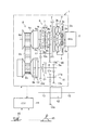
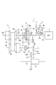
図7は、この発明で対象とすることのできる車両用変速機1の一例を示しており、この変速機1は、駆動力源としての内燃機関(以下、エンジンと記す)2の出力側に連結されて用いられる。具体的には、エンジン2の出力軸2aに、流体継ぎ手としてのロックアップクラッチ付きトルクコンバータ3が連結されている。このトルクコンバータ3は従来知られている構成のものであって、フロントカバー3aと一体のポンプインペラー3bに対向してタービンランナー3cが配置され、これらポンプインペラー3bとタービンランナー3cとの間に、一方向クラッチを介して保持されたステータ3eが配置されている。さらに、タービンランナー3cと一体となって回転するロックアップクラッチ4が、フロントカバー3aの内面に対向して配置されている。そして、ロックアップクラッチ4を挟んだ両側の圧力差に応じて、ロックアップクラッチ4がフロントカバー3aの内面に接触してトルクを伝達する係合状態、および、フロントカバー3aの内面から離れてトルクの伝達を遮断する開放状態が設定されるように構成されている。
FIG. 7 shows an example of a
上記のトルクコンバータ3におけるタービンランナー3cに、変速機1の入力軸5が連結されている。そして、入力軸5と同一軸線上に、前後進切替機構6が配置されている。この前後進切替機構6は、エンジン2から出力されたトルクをその回転方向を変えずに後述のカウンタ軸10aに伝達する前進状態と、エンジン2から出力されたトルクをその回転方向を反転してカウンタ軸10aに伝達する後進状態とに切り替えるための機構である。
The
上記の前後進切替機構6は、この図7に示す例では、3つの回転要素が互いに差動作用をなすいわゆる差動機構によって構成されている。具体的には、ダブルピニオン型の遊星歯車機構によって前後進切替機構6が構成されている。この前後進切替機構6を構成しているダブルピニオン型の遊星歯車機構は、外歯歯車であるサンギヤ6aと、サンギヤ6aに対して同心円上に配置された内歯歯車であるリングギヤ6bと、サンギヤ6aに噛み合っている第1ピニオンギヤ6cと、第1ピニオンギヤ6cならびにリングギヤ6bに噛み合っている第2ピニオンギヤ6dと、第1ピニオンギヤ6cならびに第2ピニオンギヤ6dを自転かつ公転可能に保持しているキャリヤ6eとを備えている。そして、上記のサンギヤ6aに入力軸5が連結されている。したがって、サンギヤ6aが入力要素となっている。また、リングギヤ6bの回転を選択的に止めるブレーキ機構Bが設けられている。したがって、リングギヤ6bが反力要素となっている。なお、ブレーキ機構Bは、ケーシングなどの固定部7とリングギヤ6bとの間に設けられている。このブレーキ機構Bは、例えば多板ブレーキなどの摩擦式ブレーキや噛み合い式のブレーキによって構成することができる。
In the example shown in FIG. 7, the forward /
そして、キャリヤ6eが出力要素となっている。このキャリヤ6eとサンギヤ6aもしくは入力軸5との間に、これらキャリヤ6eとサンギヤ6aとを連結して遊星歯車機構の全体を一体回転させるための第1クラッチ機構C1が設けられている。また、この第1クラッチ機構C1は入力軸5のトルクを後述するギヤ列10に選択的に伝達するためのものである。そして、第1クラッチ機構C1は摩擦力によってトルクを伝達し、そのトルク容量を連続的に変化させることができる摩擦係合機構であり、例えばクラッチディスクとクラッチプレートとを油圧によって摩擦接触させる多板クラッチによって構成され、前進走行する際の発進クラッチとなっている。
The
入力軸5のエンジン2側とは反対側(図7に示す例では左側)の端部に、ベルト式の無段変速機構(CVT)8が配置されている。このCVT8は、従来知られている構成のものと同様のものである。すなわち、駆動側の回転部材であるプライマリプーリ8aと、従動側の回転部材であるセカンダリプーリ8bと、これらのプライマリプーリ8aおよびセカンダリプーリ8bに巻き掛けられたベルト8cとを備えている。そして、プライマリプーリ8aおよびセカンダリプーリ8bは、ベルト8cが巻き掛けられている溝の幅を変化させることにより、ベルト8cの巻き掛け半径が大小に変化するように構成されている。すなわち、ベルト8cが巻き掛けられている溝幅を変化させて変速比を変更するように構成されている。
A belt-type continuously variable transmission mechanism (CVT) 8 is disposed at the end of the
プライマリプーリ8aは、入力軸5と同一軸線上で、上記の前後進切替機構6を挟んでエンジン2とは反対側に配置されている。このプライマリプーリ8aと一体のプライマリシャフト8dが、前後進切替機構6における入力要素であるサンギヤ6aに連結されている。また、セカンダリプーリ8bは、その回転中心軸線が上記のプライマリプーリ8aの回転中心軸線と平行になるように配置されている。また、セカンダリプーリ8bの回転中心軸線に沿うように設けられたセカンダリシャフト8eを備えている。そして、セカンダリシャフト8eと同一軸線上に、出力軸9が配置されている。したがって、この出力軸9は、前述した入力軸5と平行になっている。
The
そして、この出力軸9とセカンダリシャフト8eとの間に、これら出力軸9とセカンダリシャフト8eとを選択的に連結する第2クラッチ機構C2が設けられている。この第2クラッチ機構C2は、セカンダリプーリ8bと出力軸9との間でのトルクの伝達および遮断を選択的に行うことができるものであればよい。したがって、摩擦クラッチや噛み合いクラッチのいずれであってもよい。ただし、係合力に応じてトルク容量が次第に増大もしくは減少する摩擦クラッチによって構成されていることが好ましい。
A second clutch mechanism C2 that selectively connects the
この発明で制御対象とする変速機1は、上記のCVT8と並列に配置されたギヤ列10を備えている。このギヤ列10は、複数の歯車から構成された所定の一定の変速比を有する歯車伝動機構である。そして、ギヤ列10は、CVT8とは設定する変速比が異なる変速機構として構成されている。具体的には、CVT8で設定可能な最大変速比よりも大きい変速比を設定する減速機構、もしくは、CVT8で設定可能な最小変速比より小さい変速比を設定する増速機構として構成されている。この図7に示す例では、ギヤ列10は減速機構として構成されている。
The
したがって、上記の変速機1は、上記のCVT8を備えた伝動経路、すなわち、入力軸5からCVT8のプライマリプーリ8aおよびセカンダリプーリ8bを介して出力軸9に至る伝動経路と、上記のギヤ列10からなる伝動経路、すなわち、入力軸9からこのギヤ列10を介して出力軸9に至る伝動経路との2つの伝動経路を備えている。
Therefore, the
より具体的に説明すると、ギヤ列10は、入力軸5および出力軸9のそれぞれに対して平行に配置されたカウンタ軸10aを有している。カウンタ軸10aの一方(図7に示す例では右側)の端部には、カウンタドリブンギヤ10bがカウンタ軸10aと一体回転するように取り付けられている。そして、このカウンタドリブンギヤ10bに、上述の前後進切替機構6のキャリヤ6eと一体回転する駆動ギヤ6fが噛み合っている。カウンタドリブンギヤ10bは、駆動ギヤ6fよりも大径の歯車である。そのため、駆動ギヤ6fからカウンタドリブンギヤ10bへの方向には、トルクが増幅されて伝達されるようになっている。
More specifically, the
カウンタ軸10aの他方(図7に示す例では左側)の端部には、カウンタドライブギヤ10cがカウンタ軸10aと一体回転するように取り付けられている。このカウンタドライブギヤ10cは、上記のカウンタドリブンギヤ10bよりも小径の歯車である。そして、このカウンタドライブギヤ10cに、上述の出力軸9上で出力軸9に対して相対回転できるように配置された従動ギヤ10dが噛み合っている。この従動ギヤ10dはカウンタドライブギヤ10cよりも大径である。そのため、従動ギヤ10dからカウンタドライブギヤ10cへの方向には、トルクが増幅されて伝達されるようになっている。したがって、ギヤ列10の変速比(ギヤ比)は、上記の駆動ギヤ6fとカウンタドリブンギヤ10bとの間の変速比と、カウンタドライブギヤ10cと従動ギヤ10dとの間の変速比を乗算した変速比となる。この図7に示す例では、ギヤ列10の変速比は、その値がCVT8の最大変速比よりも大きくなるように構成されている。
A
さらに、従動ギヤ10dを出力軸9に動力伝達可能に連結した状態と、従動ギヤ10dと出力軸9との間の動力伝達を遮断した状態とを選択的に設定するための噛み合い式係合機構D1が設けられている。すなわち、前述した第1クラッチ機構C1に対して、トルクの伝達方向で下流側に第1クラッチ機構C1と直列に噛み合い式係合機構D1が配置され、この噛み合い式係合機構D1が係合することにより、ギヤ列10が出力軸9に対してトルクを伝達できる状態が成立するようになっている。この噛み合い式係合機構D1は、例えば可動スリーブの内周面に形成されたスプライン歯と、ハブもしくはボス部の外周面に形成されたスプライン歯とを噛み合わせてトルクを伝達する機構であり、したがって係合および開放の2つの状態に切り替わるように構成された係合機構である。すなわち、噛み合い式係合機構D1は、ドグクラッチやシンクロナイザーなどと称されている機構である。この噛み合い式係合機構D1を以下の説明では、ドグクラッチD1と記す。この図7に示す例では、ドグクラッチD1は、従動ギヤ10dのボス部に形成されたスプライン歯と、出力軸9のハブに形成したスプライン歯とにスリーブの内周面に形成されたスプライン歯を噛み合わせることにより、従動ギヤ10dを出力軸9に連結するシンクロナイザーによって構成されている。なお、そのスリーブは適宜のアクチュエータによって前後動させることができ、そのアクチュエータは油圧によって動作する油圧アクチュエータであってよい。
Further, a meshing engagement mechanism for selectively setting a state where the driven
また、出力軸9から所定のギヤ列11およびデファレンシャル12を介してドライブシャフト13にトルクを出力するように構成されている。すなわち、出力軸9のCVT8とは反対側(図7に示す例では右側)の端部に、出力ギヤ9aが取り付けられている。この出力ギヤ9aに噛み合っている大径ギヤ11aが、減速ギヤシャフト11bの一方(図7に示す例では右側)の端部に取り付けられている。減速ギヤシャフト11bの他方(図7に示す例では左側)の端部には、小径ギヤ11cが取り付けられている。この小径ギヤ11cが、デファレンシャル12のリングギヤ12aに噛み合っている。そして、デファレンシャル12は、そのリングギヤ12aを介して伝達されたトルクを、左右のドライブシャフト13から駆動輪(図示せず)に伝達するように構成されている。
The
そして、この変速機1の動作を制御する電子制御装置(ECU)14が設けられている。このECU14は、一例としてマイクロコンピュータを主体として構成されている。そして、入力されたデータおよび予め記憶しているデータに基づいて所定のプログラムに従って演算を行い、前進や後進あるいはニュートラルなどの各種の状態、および要求される変速比の設定などの制御を実行するように構成されている。
An electronic control unit (ECU) 14 that controls the operation of the
一方、ECU14には、各種センサからの検出信号や情報信号が入力されるように構成されている。例えば、プライマリプーリ8aおよびセカンダリプーリ8bの回転速度をそれぞれ検出するプーリ回転数センサ(図示せず)、シフト装置15によって選択されるシフトポジションを検出するシフトポジションセンサ(図示せず)、および車速を求めるため車両の各車輪の回転速度をそれぞれ検出する車輪速センサ(図示せず)、アクセルペダル16の踏み込み角度(アクセル開度)を検出するセンサ(図示せず)等からの検出信号が、このECU14に入力されるように構成されている。
On the other hand, the
上記のように構成された自動変速機1は、前進方向に発進する場合、および後進走行する場合に、ギヤ列10を備えたトルク伝達経路を経由して出力軸9にトルクを伝達するように制御される。そして、ある程度車速が増大した状態で前進走行する場合には、CVT8を備えたトルク伝達経路を経由して入力軸5から出力軸9にトルクを伝達するように制御される。例えば、シフト装置15によってドライブポジションが選択されると、第1クラッチ機構C1およびドグクラッチD1が係合させられ、また第2クラッチ機構C2およびブレーキ機構Bが開放させられる。
The
変速機1を制御する際の各係合機構の係合および開放の状態を、図8の表にまとめて示してある。なお、この図8で「ON」は係合していることを示し、「OFF」は開放していることを示している。
The engagement and disengagement states of the engagement mechanisms when controlling the
前進方向への発進時には、各係合機構を図8の表に示すように設定することにより、エンジン2が出力したトルクは、入力軸5を介して前後進切替機構6のサンギヤ6aに伝達される。また入力軸5は、第1クラッチ機構C1を介してキャリヤ6eに伝達される。この場合、前後進切替機構6はその2つの回転要素が第1クラッチ機構C1によって連結されているので、前後進切替機構6の全体が一体化される。入力軸5からキャリヤ6eを介して駆動ギヤ6fにトルクが伝達される。また、ギヤ列10における従動ギヤ10dが、ドグクラッチD1によって出力軸9に連結されているので、入力軸5のトルクはギヤ列10を介して出力軸9に伝達される。そして、出力ギヤ9aからギヤ列11およびデファレンシャル12を介して左右の駆動輪にトルクが伝達され、車両が発進する。
When starting in the forward direction, the torque output by the
上記のように、発進時にはギヤ列10を経由して入力軸5から出力軸9にトルクが伝達されてギヤ列10が減速機構として機能する。その場合の変速比はCVT8で設定できる最大変速比より大きい変速比となる。その結果、車両としては大きい駆動力を得ることができる。また、CVT8には発進時の大きいトルクが掛からない。そのため、CVT8のトルク容量を設定する油圧を高くする必要がない。したがって、油圧を発生させるための動力の消費が少なくなって燃費を改善することができ、また、CVT8の耐久性を向上させることができる。
As described above, torque is transmitted from the
発進後、予め決められている所定の車速にまで増速した場合は、CVT8の変速比が最大変速比もしくはそれに近い変速比に設定された状態で、第1クラッチ機構C1が開放される。それとともに、第2クラッチ機構C2が係合させられる。この場合、前後進切替機構6は、ブレーキ機構Bが開放されている状態で、更に第1クラッチ機構C1が開放されるので、いわゆる自由回転する状態になる。その結果、入力軸5とギヤ列10との間の動力伝達が遮断される。これに対して、セカンダリプーリ8bが第2クラッチ機構C2によって出力軸9に連結される。その結果、入力軸5と出力軸9とが、CVT8を経由してトルクを伝達するように連結される。したがって、CVT8による変速比を徐々に減少させること、あるいは車速とアクセル開度とに応じて変化させることにより、エンジン回転数を燃費の良い回転数に設定することができる。
When the vehicle speed is increased to a predetermined vehicle speed after starting, the first clutch mechanism C1 is released with the gear ratio of the
一方、後進走行する場合には、図8に示すように、第1クラッチ機構C1および第2クラッチ機構C2が開放されるとともに、第3クラッチ機構C3およびブレーキ機構Bが係合させられる。この場合、前後進切替機構6は、リングギヤ6bがブレーキ機構Bによって固定された状態でサンギヤ6aにエンジン2からのトルクが入力される。そのため、キャリヤ6eがサンギヤ6aに対して反対方向に回転する。したがって、前進走行の際の発進時と同様に、ギヤ列10を経由して入力軸5から出力軸9にトルクが伝達され、かつ出力軸9が後進走行する方向に回転する。この場合の変速比は、ギヤ列10による変速比と、前後進切替機構6を構成している遊星歯車機構による変速比とを乗算した変速比となる。そして、出力ギヤ9aからギヤ列11およびデファレンシャル12を介して左右の駆動輪にトルクが伝達され、後進走行する。
On the other hand, when traveling backward, as shown in FIG. 8, the first clutch mechanism C1 and the second clutch mechanism C2 are released, and the third clutch mechanism C3 and the brake mechanism B are engaged. In this case, in the forward /
そして、図8に示すように、第1クラッチ機構C1および第2クラッチ機構C2をいずれも開放させることにより、エンジン2と出力軸9との間の動力伝達を遮断したニュートラル状態を設定することができる。このように、第1クラッチ機構C1、第2クラッチ機構C2、ドグクラッチD1、およびブレーキ機構Bの係合・開放状態を制御して、前後進切替機構6の動作を制御することにより、前進状態、後進状態、およびニュートラル状態をそれぞれ設定することができる。言い換えると、動力源と同じ回転方向のトルクを出力軸9から出力する正転状態、動力源と反対の回転方向のトルクを出力軸9から出力する反転状態、および動力源と出力軸9との間の動力伝達を遮断するニュートラル状態のいずれかを選択的に設定することができる。
And as shown in FIG. 8, the neutral state which interrupted | blocked the power transmission between the
上記の変速機1では、前進走行状態から停車した場合、ドグクラッチD1は開放する場合がある。発進時以外は、CVT8によってトルクを伝達して前進走行し、車速の低下に伴ってCVT8の変速比を最大にまで変化させ、そのまま停車する場合があるからである。また、前進走行中にギヤ列10の連れ回りを防ぐ場合には、第1クラッチ機構C1を開放するから、そのまま車両が停止すれば、第1クラッチ機構C1も開放されている。一時的な停車であれば、第2クラッチ機構C2を係合させた状態に維持し、エンジン2は駆動状態に維持される。トルクコンバータ3が設けられているので、エンジンストールには到らず、またクリープトルクを発生させることができる。しかしながら、車両のメインスイッチ(図示せず)がOFFにされたり、いわゆるアイドルストップ制御が実行されると、エンジン2が停止させられ、その場合、油圧が発生しなくなるとともに、エンジン2を始動する際にエンジン2に掛かる負荷を可及的に低減するために、第2クラッチ機構C2は開放させられる。
In the
このようにエンジン2が停止している状態では、各クラッチ機構C1,C2およびドグクラッチD1ならびにブレーキ機構Bの全てが開放状態になっている。これに対して発進する場合には、第1クラッチ機構C1もしくはブレーキ機構BとドグクラッチD1とを係合状態に切り替える。その場合、第1クラッチ機構C1やブレーキ機構Bは、油圧式摩擦係合機構であるから、油圧を供給することにより所定のトルク容量を持つようになる。これに対してドグクラッチD1は、例えばスリーブに形成されているスプライン歯と従動ギヤ10dのスプライン歯とを噛み合わせる必要がある。その場合、各スプライン歯の位相が一致していると歯同士が突き当たって噛み合うことができない。このような状態をアップロック状態と称することがある。車両が停止し、かつエンジン2が停止していると、ドグクラッチD1およびギヤ列10のいずれも回転しないので、アップロック状態になると車両が発進することができない。また、ドグクラッチD1がいずれは係合するとしても、車両の発進に遅れが生じることがある。そこで、この発明に係る制御装置は、車両が停止している状態でエンジン2を始動する場合に、上記のドグクラッチD1を確実に係合させるために、以下に説明する制御を実行するように構成されている。
As described above, when the
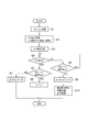
図1はその制御の一例を説明するためのフローチャートであって、ここに示すルーチンは、前述した電子制御装置14によって所定の短時間ごとに繰り返し実行される。この制御例では、先ず、イグニッションスイッチがONになるなど、所定の始動条件が成立することにより、エンジン2の始動制御が実行される(ステップS1)。これは、例えば図示しないスタータモータに通電することによりエンジン2をクランキング(モータリング)し、かつエンジン2に燃料を供給し、さらにはガソリンエンジンであれば点火プラグに通電する制御である。なお、エンジン2の始動制御は、前述したシフト装置15によってパーキングポジションもしくはニュートラルポジションが選択されて変速機1がニュートラル状態になっている場合に許可される。エンジン2の始動によって駆動トルクが急激に増大することを回避するためである。
FIG. 1 is a flowchart for explaining an example of the control, and the routine shown here is repeatedly executed at predetermined short intervals by the
ついで、第1クラッチ機構C1のトルク容量を増大させる制御が実行される。前述したように第1クラッチ機構C1が油圧式の摩擦係合機構であれば、予め定めた所定の油圧を供給する指令信号が出力される(ステップS2)。エンジン2の始動制御が実行されてエンジン2が回転すると、それに併せてオイルポンプ(図示せず)が回転して油圧を発生し、その油圧を第1クラッチ機構C1に供給する。このように第1クラッチ機構C1の油圧を増大させてそのトルク容量を増大させる制御は、エンジン2から入力軸5に伝達されているトルクによって、この発明における伝動機構に相当する前記ギヤ列10(特にその出力側の部材である従動ギヤ10d)をゆっくり回転させ、もしくは可及的に低トルクで回転させるための制御である。したがって、第1クラッチ機構C1を係合させるための予め定められた油圧は、ギヤ列10を回転させることのできる範囲で可及的に低圧に設定された油圧である。また、これは一定の圧力でなくてよく、油温やギヤ列10の回転数などをパラメータとした関数で決まる圧力であってよい。
Next, control for increasing the torque capacity of the first clutch mechanism C1 is executed. As described above, if the first clutch mechanism C1 is a hydraulic friction engagement mechanism, a command signal for supplying a predetermined oil pressure is output (step S2). When the start control of the
第1クラッチ機構C1の油圧をこのように制御することにより、第1クラッチ機構C1はその駆動側部材と被動側部材とが滑り接触するスリップ状態に設定される。そのスリップ回転数が変化し、あるいはスリップ状態と非スリップ状態とが繰り返すなどのことによってエンジン2に作用する負荷が変動し、これがエンジン回転数の変動要因になる場合には、エンジン2に設けられているアイドルスピードコントロールバルブ(ISCバルブ)によって回転数制御を行えばよい。
By controlling the hydraulic pressure of the first clutch mechanism C1 in this way, the first clutch mechanism C1 is set to a slip state in which the driving side member and the driven side member are in sliding contact. If the slip rotational speed changes or the load acting on the
このような第1クラッチ機構C1の制御と同時に、もしくは第1クラッチ機構C1の制御に続けて、前記ドグクラッチD1を係合させるために油圧を供給する指令信号が出力される(ステップS3)。すなわち、この発明では、ドグクラッチD1の係合に遅れることなく、摩擦係合機構である第1クラッチ機構C1のトルク容量を、ギヤ列10が回転する程度の低容量に増大させる制御が実行される。その後、ドグクラッチD1が係合したか否かが判断される(ステップS4)。図7に示す例では、ドグクラッチD1はスリーブを軸線方向に移動させて出力軸9と従動ギヤ10dとを連結するように構成されているから、ドグクラッチD1が係合したことは、そのスリーブのストローク量によって検出することができる。したがって、ステップS4の判断は、スリーブやこれを移動させるアクチュエータなどのストローク量をストロークセンサやストロークスイッチなどによって検出することにより行うことができる。
Simultaneously with the control of the first clutch mechanism C1 or subsequent to the control of the first clutch mechanism C1, a command signal for supplying hydraulic pressure to output the dog clutch D1 is output (step S3). In other words, in the present invention, control is executed to increase the torque capacity of the first clutch mechanism C1, which is a friction engagement mechanism, to a low capacity such that the
上述したように、ドグクラッチD1を係合させる制御は、第1クラッチ機構C1を係合させる制御を開始してギヤ列10がゆっくり、もしくは僅か回転している状態で実行される。そのため、ドグクラッチD1における互いに噛み合うべき歯同士は、当初、位相が一致していても、ドグクラッチD1におけるトルクの伝達方向で上流側の従動ギヤ10dが回転してそれらの位相がずれるから、歯同士が突き当たったままとなるアップロック状態が回避され、ドグクラッチD1を確実に、またスムースに係合させることができる。なお、停止状態で歯同士の位相が一致してアップロック状態が生じる状態になっている場合には、歯が設けられているピッチの半分の位相のずれが生じることにより歯同士を噛み合わせることができる。また、停止状態で歯同士の位相がずれていてアップロック状態が生じない状態になっている場合には、歯が設けられているピッチ程度の位相のずれが生じることにより歯同士が噛み合う。
As described above, the control for engaging the dog clutch D1 is executed in a state where the control for engaging the first clutch mechanism C1 is started and the
このようにしてドグクラッチD1が係合状態になると、第1クラッチ機構C1が既にトルク容量を持っていることにより、入力軸5と出力軸9とがギヤ列10によって連結されることになる。しかしながら、車両が停止していて駆動輪に制動力が作用し、それに伴って出力軸9の回転が止められており、また第1クラッチ機構C1のトルク容量はギヤ列10でゆっくり回転する程度の小さい容量に設定されているから、ドグクラッチD1が係合した際に第1クラッチ機構C1で滑りが生じる。すなわち、出力軸9に伝達されるトルクは僅かであるから、駆動トルクが過度に増大したり、あるいはそれに伴ってショックや車体の振動などが生じることが防止もしくは抑制される。言い換えれば、ドグクラッチD1を係合させるための制御を行うことに伴って違和感が生じることが回避もしくは抑制される。
When the dog clutch D1 is engaged as described above, the
ドグクラッチD1が係合したことにより上記のステップS4で肯定的に判断された場合には、ガレージ操作が無いか否かが判断される(ステップS5)。ガレージ操作とは、車両を発進させるためにシフト装置15でドライブポジションやリバースポジションなどのドライブ状態を選択する操作である。シフト装置15にはポジションスイッチが設けられているから、そのスイッチから出力される電気信号に基づいてステップS5の判断を行うことができる。ドライブ状態を選択する操作が行われていないことによりステップS5で肯定的に判断された場合には、低トルク容量に制御されている第1クラッチ機構C1を開放させる制御(OFFにする制御)が実行される(ステップS6)。車両の停止状態を継続するので、出力軸9にトルクを伝達する必要がないからである。その後、図1のルーチンを一旦終了する。これに対してガレージ操作が行われていてステップS5で否定的に判断された場合には、そのガレージ操作によって選択されたシフトポジションに対応したポジション信号(D信号もしくはR信号)が、ニュートラル信号(N信号)に替えて出力され(ステップS7)、その後、図1のルーチンを一旦終了する。このポジション信号は、シフトポジションをインストルメントパネル(図示せず)に表示し、あるいは油圧制御装置(図示せず)における所定のバルブを動作させるためなどの信号である。
If the determination in step S4 is affirmative due to the engagement of the dog clutch D1, it is determined whether or not there is a garage operation (step S5). The garage operation is an operation for selecting a drive state such as a drive position or a reverse position by the
一方、上記のステップS4で否定的に判断された場合、すなわちドグクラッチD1が係合したことが検出されない場合、ガレージ操作があったか否かが判断される(ステップS8)。これは、上記のステップS5における判断と同様にして行うことができる。ガレージ操作がないことによりステップS8で否定的に判断された場合には、ステップS4に戻って、従前の制御状態が継続される。これとは反対にガレージ操作があったことによりステップS8で肯定的に判断されると、そのガレージ操作によって選択されたシフトポジションに対応した信号(D信号もしくはR信号)が、ニュートラル信号(N信号)に替えて出力される(ステップS9)。 On the other hand, if a negative determination is made in step S4, that is, if it is not detected that the dog clutch D1 is engaged, it is determined whether or not a garage operation has been performed (step S8). This can be performed in the same manner as the determination in step S5. If a negative determination is made in step S8 because there is no garage operation, the process returns to step S4 and the previous control state is continued. On the contrary, if a positive determination is made in step S8 due to a garage operation, a signal (D signal or R signal) corresponding to the shift position selected by the garage operation is a neutral signal (N signal). (Step S9).
このようにしてポジション信号が出力された状態は、運転者が発進を意図し、またシフトポジションの表示がドライブ状態を示している状態であるが、ドグクラッチD1が係合していないので、出力軸9にはトルクを伝達できない状態である。したがって、アクセルペダル16が踏み込まれるなどの発進の要求があった場合には、ドグクラッチD1が開放状態であること、あるいは発進できないことを運転者に告知する警報が発せられ、またエンジン2の出力が運転者の発進要求に基づく出力よりも小さい出力に制限される(ステップS10)。その警報は、具体的には、音声によるものやランプもしくは文字での表示であってよい。また、出力の制限は、アクセルペダル16が踏み込まれても電子スロットルバルブが開かないなど、スロットル開度の制限であってよい。その後、図1のルーチンを一旦終了する。
The state in which the position signal is output in this way is a state in which the driver intends to start and the display of the shift position indicates the drive state, but since the dog clutch D1 is not engaged, the
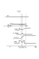
上記の制御を行った場合の各回転数や油圧などの変化を図2にタイムチャートで示してある。エンジン2を止めて停車していることにより、車速SPDおよびエンジン回転数Ne、ならびにトルクコンバータ3における出力側の回転数であるタービン回転数Ntのいずれもが「0」になっている。したがって、ドグクラッチD1の上流側の回転数すなわち従動ギヤ10dの回転数も「0」になっている。さらに、第1クラッチ機構C1およびドグクラッチD1は共に開放させられていて、それぞれには油圧が供給されておらず、その油圧は「0」もしくはそれに近い低圧になっている。
FIG. 2 is a time chart showing changes in each rotation speed and hydraulic pressure when the above control is performed. Since the
この状態でイグニッションスイッチがONにされるなどのことによりエンジン2の始動要求が成立すると(t1 時点)、エンジン2がスタータモータによってクランキングされてその回転数Neが次第に増大する。エンジン2によってオイルポンプを駆動するように構成されている車両であれば、エンジン2が回転することにより油圧が発生するので、その油圧を第1クラッチ機構C1に供給するべく、第1クラッチ機構C1の油圧の指令値が所定値に増大させられる。なお、この指令値は、前述したように、ギヤ列10をゆっくり回転させる程度の小さいトルク容量を設定する指令値であり、予め定められている。
In this state, when a request for starting the
エンジン2の始動は、変速機1のニュートラル状態で行われるから、第2クラッチ機構C2が開放していてCVT8や入力軸5は回転可能である。したがって、エンジン2がクランキングされて回転すると、トルクコンバータ3のタービン3cが入力軸5と共に回転する。その状態で、第1クラッチ機構C1がトルク容量を持ち始めることにより、ギヤ列10に入力軸5からトルクが伝達されてギヤ列10が回転し始め、その従動ギヤ10dの回転数(すなわちドグクラッチD1の上流側の回転数)が上昇し始める(t2 時点)。ドグクラッチD1の上流側の回転数が上昇している過程で、エンジン2で最初の燃焼(初爆)が生じると、エンジン回転数Neはアイドル回転数に向けて次第に低下する。また、ドグクラッチD1の上流側の回転数は、第1クラッチ機構C1のトルク容量に応じた回転数に達する。
Since the
その後、ドグクラッチD1を係合させる指令信号が出力されてその油圧が予め定めた油圧にまで増大する(t3 時点)。ドグクラッチD1やそのスリーブを移動させる機構には、僅かながらクリアランスが生じているから、そのクリアランスが詰まる動きが生じることにより油圧が僅か低下する。その後、ドグクラッチD1のスリーブが移動し始める(t4 時点)。したがって、ドグクラッチD1を係合させるアクチュエータにおける油圧室の油圧が低下し続ける。 Thereafter, a command signal for engaging the dog clutch D1 is output and the oil pressure increases to a predetermined oil pressure (at time t3). Since a slight clearance is generated in the dog clutch D1 and the mechanism for moving the sleeve, the hydraulic pressure slightly decreases due to the movement of the clearance being clogged. Thereafter, the sleeve of the dog clutch D1 starts to move (time t4). Therefore, the hydraulic pressure in the hydraulic chamber in the actuator that engages the dog clutch D1 continues to decrease.
ドグクラッチD1が従来知られているシンクロナイザーによって構成されている場合、スリーブの移動に伴ってシンクロナイザーリングのテーパー面同士が接触して回転数を同期させる作用が生じ、あるいは歯の端部に形成されているチャンファー同士が接触するので、スリーブの移動(ストローク)が一時的に停止する(t5 時点)。そのために、ドグクラッチD1の油圧の低下傾向が小さくなる。 When the dog clutch D1 is configured by a conventionally known synchronizer, the taper surfaces of the synchronizer ring come into contact with each other as the sleeve moves, and the effect of synchronizing the rotational speed is generated or formed at the end of the tooth. Since the chamfers that are in contact with each other, the movement (stroke) of the sleeve temporarily stops (at time t5). For this reason, the tendency of the hydraulic pressure of the dog clutch D1 to decrease is reduced.
前述したように、この発明に係る制御装置によれば、第1クラッチ機構C1を小さいトルク容量となるように係合させてドグクラッチD1の上流側で回転を生じさせているので、ドグクラッチD1における互いに噛み合う歯の位相にずれが生じる。そのため、歯同士が突き当たってもその状態が直ちに解消され、歯同士が噛み合うべくスリーブが移動する。すなわち上記のt5 時点の直後にスリーブが更に移動し、ドグクラッチD1が実質的に係合し始める(t6 時点)。その場合、歯同士が噛み合うことに伴う摺動抵抗が作用するので、ドグクラッチD1の油圧が上昇する。 As described above, according to the control device of the present invention, the first clutch mechanism C1 is engaged so as to have a small torque capacity and the upstream side of the dog clutch D1 is caused to rotate. There is a shift in the phase of the meshing teeth. Therefore, even if the teeth collide with each other, the state is immediately eliminated, and the sleeve moves so that the teeth mesh with each other. That is, immediately after the time t5, the sleeve further moves, and the dog clutch D1 starts to be substantially engaged (time t6). In that case, since the sliding resistance accompanying the meshing of teeth acts, the hydraulic pressure of the dog clutch D1 increases.
そして、スリーブがストロークエンドに達するとドグクラッチD1の係合が完了する(t7 時点)。この場合、車両が停止していて出力軸9が回転していないから、ドグクラッチD1が係合することによりドグクラッチD1の上流側の回転数が低下し、ついには停止する。このドグクラッチD1の係合が検出されると、スリーブはそれ以上には移動しないので、ドグクラッチD1の油圧が指令値に応じた圧力まで上昇する。その係合状態を確立するために油圧が維持され、その後にドグクラッチD1の油圧が低下させられる(t8 時点)。ドグクラッチD1は係合状態および開放状態をそれぞれ維持するように構成されているので、油圧を低下させても完全係合状態を維持する。
When the sleeve reaches the stroke end, the engagement of the dog clutch D1 is completed (at time t7). In this case, since the vehicle is stopped and the
上記の図2を参照して説明したように、この発明に係る制御装置によれば、車両が停止している状態でエンジン2を始動することに伴って、この発明における伝動機構であるギヤ列10を出力軸9に連結するドグクラッチD1を係合させる場合、ドグクラッチD1の上流側の部材(従動ギヤ10d)を小さいトルクで回転させる。したがって、この発明に係る制御装置によれば、エンジン2の始動前にドグクラッチD1における互いに噛み合う歯同士の位相が一致していても、いわゆるアップロックを回避して、ドグクラッチD1を確実に、またスムースに係合させることができる。
As described with reference to FIG. 2 above, according to the control device of the present invention, the gear train which is the transmission mechanism in the present invention is accompanied by starting the
つぎに、この発明に係る制御装置で実行される他の制御例を説明する。前述したドグクラッチD1の上流側の回転数を増大させるための摩擦係合機構は、ドライブ状態を設定する際に係合させられる機構である。図7に示す構成の変速機1においては、その摩擦係合機構は、前進状態を設定する第1クラッチ機構C1や後進状態を設定するブレーキ機構Bである。したがって、これらの摩擦係合機構はシフト装置15によってドライブポジションあるいはリバースポジションが選択されることにより、油圧が供給されて係合させられる。そこで、この発明に係る制御装置では、そのようなシフト操作(ガレージ操作)を利用してドグクラッチD1を係合させる際の伝動機構の回転を生じさせてもよい。
Next, another example of control executed by the control device according to the present invention will be described. The aforementioned friction engagement mechanism for increasing the number of rotations on the upstream side of the dog clutch D1 is a mechanism that is engaged when setting the drive state. In the
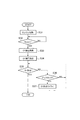
図3はその制御例を説明するためのフローチャートであって、ここに示すルーチンは、前述した電子制御装置14によって所定の短時間ごとに繰り返し実行される。この制御例では、先ず、イグニッションスイッチがONになるなど、所定の始動条件が成立することにより、エンジン2の始動制御が実行される(ステップS21)。これは、前述した図1に示す制御例におけるステップS1と同様の制御である。ついで、ガレージ操作が実行されたか否かが判断される(ステップS22)。これは、前述した図1に示す制御例におけるステップS8と同様の判断ステップであって、シフト装置15から信号が出力されたか否かによって判断することができる。このステップS22で否定的に判断された場合、すなわちガレージ操作が行われていない場合に、新たな制御を開始することなく従前の制御状態が継続される。
FIG. 3 is a flowchart for explaining the control example, and the routine shown here is repeatedly executed by the
これに対してガレージ操作が実行されたことによりステップS22で肯定的に判断された場合には、その操作によって選択されたポジションに対応する信号(D信号もしくはR信号)が、ニュートラル信号(N信号)に替えて出力される(ステップS23)。図3に示す制御例では、このポジション信号に基づいて第1クラッチ機構C1あるいはブレーキ機構Bの制御が行われる。すなわち、これらの摩擦係合機構は、車両を走行させるためのトルクを伝達する機構であるから、最終的にはアクセル開度などの駆動要求量に基づいて定まるトルク容量(油圧)に設定されるが、係合開始当初は、前述した図1における制御例におけるステップS2での制御と同様に、小さいトルク容量に設定される。具体的には、この発明における伝動機構に相当するギヤ列10がゆっくり回転する程度の小さいトルクを伝達する油圧が第1クラッチ機構C1あるいはブレーキ機構Bに供給される。その油圧は、油温や回転数などに基づいて決まる油圧であってよいことは、図1に示す制御例と同様である。
On the other hand, if a positive determination is made in step S22 by executing the garage operation, a signal (D signal or R signal) corresponding to the position selected by the operation is a neutral signal (N signal). ) And output (step S23). In the control example shown in FIG. 3, the first clutch mechanism C1 or the brake mechanism B is controlled based on this position signal. In other words, these friction engagement mechanisms are mechanisms that transmit torque for running the vehicle, and are finally set to a torque capacity (hydraulic pressure) determined based on a required drive amount such as the accelerator opening. However, at the beginning of engagement, the torque capacity is set to a small value as in the control in step S2 in the control example in FIG. Specifically, hydraulic pressure that transmits a torque that is small enough to cause the
これと同時に、もしくは続けて、ドグクラッチD1を係合させるべく油圧が供給される(ステップS24)。これは、前述した図1に示す制御例におけるステップS3の制御と同様の制御である。ドグクラッチD1に油圧が供給されると、図7に示す構成の変速機1においては、ドグクラッチD1のスリーブが軸線方向に移動させられる。その場合、第1クラッチ機構C1もしくはブレーキ機構Bが低トルク容量で係合していてギヤ列10がゆっくり回転しているので、ドグクラッチD1における歯同士の位相が一致したままになることがなく、スリーブの移動に伴ってそれらの歯同士が互いに噛み合う。すなわち、アップロックが発生することがなく、あるいはアップロックが直ちに解消される。
At the same time or subsequently, the hydraulic pressure is supplied to engage the dog clutch D1 (step S24). This is the same control as the control in step S3 in the control example shown in FIG. When hydraulic pressure is supplied to the dog clutch D1, the sleeve of the dog clutch D1 is moved in the axial direction in the
上記のステップS24でドグクラッチD1に油圧を印加した後、図1に示す制御例と同様に、ドグクラッチD1が係合したか否かが判断される(ステップS25)。なお、図3のルーチンは、所定の短時間毎に繰り返し実行されるから、ドグクラッチD1が係合したか否かの判断は、図3のルーチンのサイクル時間内(所定時間内)に係合したか否かを判断していることになる。ドグクラッチD1が係合していてステップS25で肯定的に判断された場合には、図3に示す制御は一旦終了される。これとは反対にドグクラッチD1が係合したことが検出されないことによりステップS25で否定的に判断された場合には、いわゆるアップロック状態が生じているか否かが判断される(ステップS26)。この判断は、スリーブが所定寸法移動したか否かによって判断することができる。 After the hydraulic pressure is applied to the dog clutch D1 in the above step S24, it is determined whether the dog clutch D1 is engaged, as in the control example shown in FIG. 1 (step S25). Since the routine of FIG. 3 is repeatedly executed every predetermined short time, it is determined whether or not the dog clutch D1 is engaged within the cycle time (predetermined time) of the routine of FIG. It will be judged whether or not. If the dog clutch D1 is engaged and a positive determination is made in step S25, the control shown in FIG. 3 is temporarily terminated. On the other hand, if it is determined negative in step S25 because it is not detected that the dog clutch D1 is engaged, it is determined whether or not a so-called uplock state has occurred (step S26). This determination can be made based on whether or not the sleeve has moved by a predetermined dimension.
ステップS26で肯定的に判断された場合にはドグクラッチD1を係合させる制御が再度実行される(ステップS27)。この制御は、ドグクラッチD1を係合させる油圧を一旦低下し、もしくは解除し、その後に再度油圧を供給する制御である。そして、ステップS25の前に戻り、再度、ドグクラッチD1の係合が判断される。なお、スリーブが所定寸法移動していないなど、アップロックが生じていないことによりステップS26で否定的に判断された場合には、ステップS25の前に戻って、ドグクラッチD1を係合させる制御が継続される。 If the determination in step S26 is affirmative, the control for engaging the dog clutch D1 is executed again (step S27). In this control, the hydraulic pressure for engaging the dog clutch D1 is temporarily reduced or released, and then the hydraulic pressure is supplied again. And it returns before step S25 and the engagement of the dog clutch D1 is judged again. Note that if a negative determination is made in step S26 because no up-lock has occurred, for example, the sleeve has not moved by a predetermined dimension, the control returns to step S25 and the dog clutch D1 is engaged. Is done.
図3に示す制御を実行した場合の各回転数や油圧などの変化を図4にタイムチャートで示してある。エンジン2を止めて停車している状態では、車速SPDおよびエンジン回転数Neならびにタービン回転数Ntのいずれもが「0」になっており、その状態でエンジン2が始動されると(t21時点)、エンジン回転数Neが上昇し、それに僅か遅れてタービン回転数Nt(すなわち入力軸回転数)が上昇する。その後のt22時点に、ニュートラル(N)ポジションもしくはパーキング(P)ポジションからドライブ(D)ポジションに切り替えるシフト操作(ガレージ操作)が行われると、第1クラッチ機構C1を低トルク容量で係合させる制御、およびドグクラッチD1を係合させる制御が開始される。その第1クラッチ機構C1の係合制御について説明すると、供給圧が一時的に高い油圧に設定される。これは、ファーストフィルと称される制御であって、第1クラッチ機構C1に生じているクリアランス(パック)を詰めるための制御である。その後のt23時点に、第1クラッチ機構C1の油圧は、ギヤ列10をゆっくり回転させる程度の低トルク容量となる油圧に低下させられ、維持される。また、ドグクラッチD1の油圧はパックが詰まるなどのことによるスリーブの移動が生じるので、低下し始める。
FIG. 4 is a time chart showing changes in each rotation speed and hydraulic pressure when the control shown in FIG. 3 is executed. In a state where the
こうして第1クラッチ機構C1のトルク容量が次第に大きくなると、ギヤ列10にトルクが伝達されてギヤ列10が回転し始める。すなわちドグクラッチD1の上流側の回転数が上昇し始める。以降、前述した図2に示す場合と同様に、各回転数および油圧が変化する。これを簡単に説明すると、t24時点にドグクラッチD1のスリーブがストロークし始める。その結果、シンクロナイザーリングのテーパー面が相手側のテーパー面に接触し、あるいは歯同士が接触すると、スリーブのストロークが一旦止まり(t25時点)、ドグクラッチD1の油圧の低下が少なくなり、あるいは一定圧になる。ドグクラッチD1の上流側の部材(すなわち従動ギヤ10d)が回転していることにより、t26時点に歯同士の実質的な噛み合いが始まる。すなわち、スリーブが更にストロークする。その場合、歯同士が噛み合うことによる摺動抵抗などによって油圧が上昇する。また、ドグクラッチD1が係合することによりギヤ列10が、回転していない出力軸9に連結されるから、ドグクラッチD1の上流側の回転数が停止に向けて低下する。そして、t27時点にスリーブがストロークエンドに達してドグクラッチD1が実質的に完全に係合し、それに伴って油圧が指示油圧に達してその油圧が維持される。その後のt28時点にドグクラッチD1の油圧が係合状態を維持する油圧に設定されてその係合制御が完了する。なお、係合状態を維持する機構を備えている場合には、油圧を「0」に戻すこととしてもよい。
Thus, when the torque capacity of the first clutch mechanism C1 gradually increases, torque is transmitted to the
一方、第1クラッチ機構C1の油圧は、ドグクラッチD1の実質的な係合が開始するt26時点までは低い油圧に維持されるが、ドグクラッチD1の実質的な係合が開始すると、車両に対する駆動要求量に応じた油圧に向けて次第に増大させられる。そして、ドグクラッチD1の係合制御が完了したt28時点以降に第1クラッチ機構C1の油圧が駆動要求量に応じた油圧に達し(t29時点)、その油圧に維持される。 On the other hand, the hydraulic pressure of the first clutch mechanism C1 is maintained at a low hydraulic pressure until time t26 when the substantial engagement of the dog clutch D1 starts, but when the substantial engagement of the dog clutch D1 starts, a drive request to the vehicle is made. It is gradually increased toward the hydraulic pressure according to the amount. Then, after the time t28 when the engagement control of the dog clutch D1 is completed, the hydraulic pressure of the first clutch mechanism C1 reaches the hydraulic pressure corresponding to the requested drive amount (at the time t29) and is maintained at that hydraulic pressure.
したがって、図3に示す制御を行うように構成した場合であっても、エンジン2を始動する際にドグクラッチD1を係合させる場合、エンジン2の始動前にドグクラッチD1における互いに噛み合う歯同士の位相が一致していても、いわゆるアップロックを回避して、ドグクラッチD1を確実に、またスムースに係合させることができる。
Therefore, even when the control shown in FIG. 3 is performed, when the dog clutch D1 is engaged when the
上述した各具体例は、エンジン2の始動制御におけるエンジン2の初爆の以降にドグクラッチD1の係合制御を開始する例であるが、この発明では、更に早い時点にドグクラッチD1の係合制御を開始して、車両の発進の遅れが回避もしくは抑制されるように構成することができる。図5にその制御の一例を示してあり、ここに示す例は、エンジン2の始動(クランキング)の開始後、エンジン回転数Neが予め定めた基準値C以上になったことを条件として第1クラッチ機構C1およびドグクラッチD1の係合制御を開始するように構成した例である。なお、この基準値Cは、エンジン2の始動制御の開始からの経過時間であってもよい。
Each of the specific examples described above is an example in which the engagement control of the dog clutch D1 is started after the initial explosion of the
具体的に説明すると、図5に示すルーチンは前述した電子制御装置14によって所定の短時間ごとに繰り返し実行され、この制御例では、先ず、エンジン2の始動制御が実行される(ステップS31)。これは、前述した図1に示す制御例におけるステップS1と同様の制御である。ついで、クランキングされているエンジン2の回転数Neが予め定めた基準値C以上になったか否かが判断される(ステップS32)。この基準値Cは、以下に述べる第1クラッチ機構C1およびドグクラッチD1の係合制御の開始のタイミングを決める回転数であって、エンジン2で初爆が生じる回転数より小さい値に設定されている。より具体的には、ドグクラッチD1の係合制御を開始した後、実質的に係合し始めるまでの時間を求めておき、その時間だけ、初爆が生じる時点より前の時点でのエンジン回転数の予測値を基準値Cとすればよい。
Specifically, the routine shown in FIG. 5 is repeatedly executed every predetermined short time by the
エンジン回転数Neが基準値Cを下回っていることによりステップS32で否定的に判断された場合には、新たな制御を行うことなく従前のエンジン始動制御が継続される。これに対して、エンジン回転数Neが基準値C以上になったことによりステップS32で肯定的に判断された場合には、第1クラッチ機構C1およびドグクラッチD1のそれぞれに油圧が供給されてそれらの係合制御が開始される(ステップS33、ステップS34)。これらの制御は前述した図1に示す制御におけるステップS2およびステップS3での制御と同様の制御であり、第1クラッチ機構C1にはギヤ列10をゆっくり回転させることができる程度のトルク容量を設定する油圧が供給される。また、ドグクラッチD1には例えばそのスリーブを係合方向に移動させることのできる油圧が供給される。
If the negative determination is made in step S32 because the engine speed Ne is below the reference value C, the previous engine start control is continued without performing new control. On the other hand, if the determination at step S32 is affirmative because the engine speed Ne is equal to or greater than the reference value C, the hydraulic pressure is supplied to each of the first clutch mechanism C1 and the dog clutch D1, and the engine clutch Ne Engagement control is started (step S33, step S34). These controls are the same as the controls in steps S2 and S3 in the control shown in FIG. 1 described above, and the first clutch mechanism C1 is set with a torque capacity that allows the
その後、ドグクラッチD1が係合したか否かが判断される(ステップS35)。ドグクラッチD1が係合していることによりステップS35で肯定的に判断された場合には、図5に示すルーチンが一旦終了される。これに対してドグクラッチD1が係合していることが検出されないことによりステップS35で否定的に判断された場合には、アップロック状態になっているか否かが判断される(ステップS36)。アップロック状態が生じていることによりステップS36で肯定的に判断された場合には、ドグクラッチD1を係合させる制御が再度実行され(ステップS37)、その後、ステップS35の前に戻って、ドグクラッチD1を係合させる制御が継続される。なお、スリーブが所定寸法移動していないなど、アップロックが生じていないことによりステップS36で否定的に判断された場合には、ステップS35の前に戻って、ドグクラッチD1を係合させる制御が継続される。これらステップS35ないしステップS37の制御は、前述した図3に示す制御例におけるステップS25ないしステップS27の制御と同様の制御である。 Thereafter, it is determined whether or not the dog clutch D1 is engaged (step S35). If the determination in step S35 is affirmative because the dog clutch D1 is engaged, the routine shown in FIG. 5 is temporarily terminated. On the other hand, if it is determined negative in step S35 because it is not detected that the dog clutch D1 is engaged, it is determined whether or not it is in an uplock state (step S36). If the determination in step S36 is affirmative due to the occurrence of the uplock state, the control for engaging the dog clutch D1 is executed again (step S37), and then the process returns to the state before step S35 and the dog clutch D1 is returned. The control to engage is continued. If a negative determination is made in step S36 because no up-lock has occurred, for example, the sleeve has not moved by a predetermined dimension, the control returns to step S35 and the dog clutch D1 is engaged. Is done. The control in steps S35 to S37 is the same as the control in steps S25 to S27 in the control example shown in FIG.
上述した図5に示す制御を行った場合の各回転数や油圧などの変化を図6にタイムチャートで示してある。エンジン2を止めて停車している状態でエンジン2が始動されると(t31時点)、エンジン2がクランキングされてその回転数Neが上昇し始め、それに僅か遅れてタービン回転数Ntが上昇し始めるが、前述した基準値Cが小さい値であるから、エンジン2の始動開始の直後に第1クラッチ機構C1およびドグクラッチD1の油圧を上昇させる制御が開始される。第1クラッチ機構C1に供給する油圧は、ギヤ列10がゆっくり回転する程度のトルク容量を設定する油圧であり、したがってt32時点にギヤ列10が回転し始め、ドグクラッチD1の上流側の回転数が次第に上昇する。
FIG. 6 is a time chart showing changes in each rotation speed and hydraulic pressure when the control shown in FIG. 5 is performed. When the
一方、ドグクラッチD1にはこれを係合状態にする油圧が供給されているから、エンジン2の初爆とほぼ同時にスリーブが移動し始めて実質的に係合し始める(t33時点)。ドグクラッチD1の油圧は前述した図2あるいは図4に示す例と同様に変化し、その場合、ドグクラッチD1によってギヤ列10が連結される出力軸9が停止しているから、ドグクラッチD1が係合し始めるとその上流側の回転数が次第に引き下げられ、ついにはその回転が止まる。そして、エンジン2が自立回転し始めてアイドリング回転数程度のエンジン回転数になるとほぼ同時にドグクラッチD1が完全に係合する(t34時点)。すなわち、スリーブがストロークエンドに達する。その後、ドグクラッチD1が完全に係合した状態を確立するための時間が経過したt35時点にドグクラッチD1の油圧が低下させられる。
On the other hand, the dog clutch D1 is supplied with a hydraulic pressure that brings it into an engaged state, so that the sleeve starts to move substantially at the same time as the first explosion of the
したがって、図5に示す制御を行うように構成されていれば、エンジン2の始動の完了とほぼ同時にドグクラッチD1の係合が完了する。そのため、このような構成であれば、噛み合い式係合機構であるドグクラッチD1のいわゆるアップロック状態を回避できるとともに、その係合速度を速くして係合に要する時間を短縮することができる。言い換えれば、いわゆる発進待機状態を迅速に成立させることができる。
Therefore, if the control shown in FIG. 5 is performed, the engagement of the dog clutch D1 is completed almost simultaneously with the completion of the start of the
なお、この発明で対象とする変速機は、入力軸と出力軸との間に無段変速機構と変速比が一定の伝動機構とが並列に設けられ、入力軸のトルクをその伝動機構に伝達する摩擦係合機構と、その摩擦係合機構に対してトルクの伝達方向で下流側に直列に配列されて前記伝動機構を出力軸に対してトルク伝達可能な状態にする噛み合い式係合機構とが設けられている変速機であればよい。その例を以下に簡単に説明する。なお、以下に説明する構成は、前述した図7に示す構成における第1クラッチ機構C1やドグクラッチD1あるいは前後進切替機構6の位置を変更したものであるから、図7に示す構成部材と同じ構成部材には図7と同じ符号を付してその詳細な説明を省略する。
In the transmission targeted by the present invention, a continuously variable transmission mechanism and a transmission mechanism with a constant transmission ratio are provided in parallel between the input shaft and the output shaft, and the torque of the input shaft is transmitted to the transmission mechanism. A friction engagement mechanism that engages with the friction engagement mechanism, and a meshing engagement mechanism that is arranged in series downstream in the torque transmission direction with respect to the friction engagement mechanism and that allows the transmission mechanism to transmit torque to the output shaft. Any transmission that is provided may be used. An example is briefly described below. The configuration described below is the same as the configuration member shown in FIG. 7 because the position of the first clutch mechanism C1, the dog clutch D1, or the forward /
図9に示す例は、前述した図7に示す構成のうち、第2クラッチ機構C2およびドグクラッチD1を入力軸5と同一の軸線上に配置し、それに伴って他の部材の位置の変更を行った例である。したがって、ドグクラッチD1は第1クラッチ機構C1に対してトルクの伝達方向で下流側に直列に配列され、ギヤ列10の一部となっている駆動ギヤ6fとキャリヤ6eとを選択的に連結して、ギヤ列10を入力軸5と出力軸9との間でトルクを伝達できるようにする係合機構である。また、第2クラッチ機構C2は入力軸5とプライマリプーリ8aとの間に配置されてこれら入力軸5とプライマリプーリ8aとを選択的に連結するように構成されている。それに伴って出力軸9はセカンダリプーリ8bに一体となって回転するように連結されている。他の構成は図7に示す構成と同様である。
In the example shown in FIG. 9, in the configuration shown in FIG. 7 described above, the second clutch mechanism C2 and the dog clutch D1 are arranged on the same axis as the
図10に示す例は、前述した図7に示す構成のうち、第2クラッチ機構C2を入力軸5と同一の軸線上に配置し、その第2クラッチ機構C2によって入力軸5とプライマリプーリ8aとを選択的に連結するように構成し、それに伴って他の部材の位置の変更を行った例である。第2クラッチ機構C2を入力軸5と同一の軸線上に配置したことに伴い、出力軸9はセカンダリプーリ8bに一体となって回転するように連結されている。他の構成は図7に示す構成と同様である。
In the example shown in FIG. 10, in the configuration shown in FIG. 7 described above, the second clutch mechanism C2 is arranged on the same axis as the
図11に示す例は、前述した図7に示す構成のうち、ドグクラッチD1をカウンタ軸10a上に配置し、また第2クラッチ機構C2を入力軸5と同一の軸線上に配置し、それに伴って他の部材の位置の変更を行った例である。したがって、ドグクラッチD1はカウンタドリブンギヤ10bとカウンタ軸10aとを選択的に連結するように構成されている。また、第2クラッチ機構C2は入力軸5とプライマリプーリ8aとを選択的に連結するように構成されている。他の構成は、図7に示す構成と同様である。
In the example shown in FIG. 11, in the configuration shown in FIG. 7 described above, the dog clutch D1 is arranged on the
図12に示す例は、前述した図7に示す構成のうち、ドグクラッチD1を入力軸5と同一の軸線上に配置し、そのドグクラッチD1によって入力軸5と駆動ギヤ6fとを選択的に連結するように構成し、それに伴って他の部材の位置の変更を行った例である。他の構成は図7に示す構成と同様である。
In the example shown in FIG. 12, the dog clutch D1 is arranged on the same axis as the
図13に示す例は、前述した図7に示す構成のうち、第1クラッチ機構C1と駆動ギヤ6fとの位置を、入力軸5の軸線上で入れ替え、それに伴ってカウンタドリブンギヤ10bおよびカウンタドライブギヤ10cの位置をカウンタ軸10a上で入れ替え、それに伴って他の部材の位置の変更を行った例である。他の構成は図7に示す構成と同様である。
In the example shown in FIG. 13, the positions of the first clutch mechanism C1 and the
図14に示す例は、前述した図7に示す構成のうち、ドグクラッチD1をカウンタ軸10a上に配置し、それに伴って他の部材の位置の変更を行った例である。したがって、ドグクラッチD1はカウンタドリブンギヤ10bとカウンタ軸10aとを選択的に連結するように構成されている。他の構成は、図7に示す構成と同様である。
The example shown in FIG. 14 is an example in which, in the configuration shown in FIG. 7 described above, the dog clutch D1 is arranged on the
図15に示す例は、前述した図7に示す構成のうち、前後進切替機構6および第1クラッチ機構C1をカウンタ軸10a上に配置し、また第2クラッチ機構C2を入力軸5と同一の軸線上に配置し、それに伴って他の部材の位置の変更を行った例である。したがって、前後進切替機構6におけるサンギヤ6aがカウンタ軸10aに一体化され、キャリヤ6eがカウンタドリブンギヤ10bに連結され、さらに第1クラッチ機構C1はそのキャリヤ6eとカウンタ軸10aを選択的に連結するように構成されている。この構成であっても、第1クラッチ機構C1は入力軸5のトルクをギヤ列10に伝達するようになっており、ドグクラッチD1はその第1クラッチ機構C1の下流側に直列に配列され、出力軸9にトルクを伝達するように構成されている。また、駆動ギヤ6fは入力軸5に一体化され、さらに、第2クラッチ機構C2は入力軸5とプライマリプーリ8aとを選択的に連結するように構成されている。他の構成は、図7に示す構成と同様である。
In the example shown in FIG. 15, the forward /
そして、図16に示す例は、前述した図7に示す構成のうち、前後進切替機構6をカウンタ軸10a上に配置し、それに伴って駆動ギヤ6fを入力軸5に一体化させ、さらに他の部材の位置の変更を行った例である。したがって、前後進切替機構6におけるサンギヤ6aがカウンタ軸10aに一体化され、キャリヤ6eがカウンタドリブンギヤ10bに連結され、さらに第1クラッチ機構C1はそのキャリヤ6eとカウンタ軸10aを選択的に連結するように構成されている。この構成であっても、第1クラッチ機構C1は入力軸5のトルクをギヤ列10に伝達するようになっており、ドグクラッチD1はその第1クラッチ機構C1の下流側に直列に配列され、出力軸9にトルクを伝達するように構成されている。他の構成は、図7に示す構成と同様である。
In the example shown in FIG. 16, the forward /
この発明に係る制御装置は、これら図9ないし図16に示すいずれの構成の変速機であっても、ドグクラッチD1のアップロックを回避もしくは抑制してドグクラッチD1を確実に、またスムースに係合させることができる。 The control device according to the present invention ensures that the dog clutch D1 is smoothly and smoothly engaged by avoiding or suppressing the up-lock of the dog clutch D1 in any of the transmissions shown in FIGS. be able to.
なお、この発明における入力部材や出力部材は、上述した入力軸5や出力軸9などの回転軸以外に、歯車であってもよい。また、無段変速機構はベルト式のものに限定されないのであって、トロイダル型のものであってもよい。さらに、この発明における伝動機構は、歯車伝動機構に限られず、チェーン式の伝動機構であってもよい。
The input member and the output member in the present invention may be gears other than the rotation shafts such as the
1…変速機、 2…内燃機関(エンジン)、 3…ロックアップクラッチ付きトルクコンバータ、 5…入力軸、 6…前後進切替機構、 B…ブレーキ機構、 C1…第1クラッチ機構、 8…無段変速機構(CVT)、 8a…プライマリプーリ、 8b…セカンダリプーリ、 8c…ベルト、 9…出力軸、 C2…第2クラッチ機構、 10…ギヤ列、 10a…カウンタ軸、 10b…カウンタドリブンギヤ、 6f…駆動ギヤ、 10c…カウンタドライブギヤ、 10d…従動ギヤ、 D1…噛み合い式係合機構(ドグクラッチ)、 9a…出力ギヤ、 14…電子制御装置(ECU)、 15…シフト装置、 16…アクセルペダル。
DESCRIPTION OF
Claims (13)
前記摩擦係合機構および噛み合い式係合機構が共に開放していて前記伝動機構がトルクを伝達できない状態から前記噛み合い式係合機構を係合させて前記伝動機構を前記出力部材にトルクを伝達できる状態にする際に、前記摩擦係合機構のトルク容量を前記伝動機構が回転するトルク容量に増大させた後、前記噛み合い式係合機構が係合し始めるように、前記摩擦係合機構への油圧の供給の開始以後に前記噛み合い式係合機構を係合させるための油圧供給指令を開始するように構成されていることを特徴とする車両用変速機の制御装置。
A continuously variable transmission mechanism and the transfer moving mechanism between an output member of the torque from the driving force source to output a torque to the input member and the drive wheel to be transmitted is provided in parallel, torque corresponding to the hydraulic pressure supplied a friction engagement mechanism reaching transferred to the transmission mechanism from the input member, said the sequence downstream of the frictional engagement mechanism transmitting direction from the input member torque toward the output member, or one is supplied in a control device for a vehicle transmission in which a meshing type engagement mechanism into a state capable torque transmission is provided between said input member and the output member before Symbol transmission mechanism based on hydraulic that,
The transmission mechanism can transmit torque to the output member by engaging the engagement type engagement mechanism from a state where the friction engagement mechanism and the engagement type engagement mechanism are both open and the transmission mechanism cannot transmit torque. when the state, after the torque capacity of the friction engagement mechanism front Symbol transmission mechanism increased in torque capacity to rotate, such that the meshing type engagement mechanism begin to engage, to the friction engagement mechanism hydraulic control device for a vehicle transmission characterized in that it consists to begin hydraulic supply command for engaging the meshing type engagement mechanism since the start of the supply of.
前記摩擦係合機構および噛み合い式係合機構が共に開放している状態から前記噛み合い式係合機構を係合させて前記伝動機構を前記出力部材にトルクを伝達できる状態にする制御は、前記内燃機関がクランキングされて始動される際に実行されるように構成されていることを特徴とする請求項1に記載の車両用変速機の制御装置。 The driving force source includes an internal combustion engine that is cranked and started,
The control for causing the transmission mechanism to transmit torque to the output member by engaging the meshing engagement mechanism from the state where both the frictional engagement mechanism and the meshing engagement mechanism are open is the internal combustion engine. 2. The control device for a vehicle transmission according to claim 1, wherein the control device is executed when the engine is cranked and started.
前記クランキングは、前記ニュートラル状態が選択されている場合に実行されるように構成され、
前記噛み合い式係合機構が係合した後に前記ドライブ状態が選択されていない場合には前記摩擦係合機構を開放するように構成されている
ことを特徴とする請求項2に記載の車両用変速機の制御装置。
A shift mechanism for selecting a neutral state in which the torque output from the internal combustion engine is not transmitted to the drive wheels and a drive state in which a predetermined gear ratio is set;
Before SL cranking, the neutral state is arranged to be executed when it is selected,
When the drive state is not selected after the meshing engagement mechanism is engaged, the friction engagement mechanism is opened.
A control device for a vehicle transmission according to claim 2, wherein the this.
ことを特徴とする請求項1ないし3のいずれかに記載の車両用変速機の制御装置。
Hydraulic pressure, one of the claims 1 to 3, characterized in that it is set based on at least one of the rotational speed and the oil temperature of the transmission mechanism before Symbol transmission mechanism sets the torque capacity enough to rotate A control device for a vehicle transmission according to claim 1.
前記伝動機構が回転する程度のトルク容量は、前記駆動側部材と被動側部材とを滑り接触させて設定されるトルク容量を含む
ことを特徴とする請求項1ないし4のいずれかに記載の車両用変速機の制御装置。 Before SL frictional engagement mechanism, which has a drive-side member and the driven-side member includes a mechanism capable of transmitting torque in a state in which the these drive-side member and the driven-side member are in sliding contact with,
Torque capacity enough to pre Symbol transmission mechanism rotates includes a torque capacity which is set between the driving-side member and the driven-side member by sliding contact
A control device for a vehicle transmission according to claim 1 of stone 4, wherein the arc.
前記クランキングは、前記ニュートラル状態が選択されている場合に実行されるように構成され、
前記摩擦係合機構のトルク容量の増大は、前記シフト機構によって前記ドライブ状態が選択されることによりそのドライブ状態を成立させるための摩擦係合機構のトルク容量を前記クランキングの開始後に増大させることにより実行される
ことを特徴とする請求項2に記載の車両用変速機の制御装置。 A shift mechanism for selecting a neutral state in which the torque output from the internal combustion engine is not transmitted to the drive wheels and a drive state in which a predetermined gear ratio is set;
The cranking is configured to be performed when the neutral state is selected;
Increasing the torque capacity of the friction engagement mechanism is to increase the torque capacity of the friction engagement mechanism for establishing the drive state after the start of cranking by selecting the drive state by the shift mechanism. The vehicle transmission control device according to claim 2, wherein the vehicle transmission control device is executed.
前記伝動機構は、前記ベルト式無段変速機構による最大変速比より大きい変速比もしくは前記ベルト式無段変速機構による最小変速比より小さい変速比を有する歯車機構を含むことを特徴とする請求項1ないし10のいずれかに記載の車両用変速機の制御装置。 The continuously variable transmission mechanism includes a belt, and a belt-type continuously variable transmission mechanism in which the belt is wound and the winding radius of the belt continuously changes by changing the width of the groove,
2. The transmission mechanism according to claim 1, wherein the transmission mechanism includes a gear mechanism having a speed ratio larger than a maximum speed ratio by the belt type continuously variable transmission mechanism or a speed ratio smaller than a minimum speed ratio by the belt type continuously variable transmission mechanism. 11. The control device for a vehicle transmission according to any one of claims 10 to 10.
Priority Applications (1)
| Application Number | Priority Date | Filing Date | Title |
|---|---|---|---|
| JP2014222606A JP6142859B2 (en) | 2014-10-31 | 2014-10-31 | Control device for vehicle transmission |
Applications Claiming Priority (1)
| Application Number | Priority Date | Filing Date | Title |
|---|---|---|---|
| JP2014222606A JP6142859B2 (en) | 2014-10-31 | 2014-10-31 | Control device for vehicle transmission |
Related Parent Applications (1)
| Application Number | Title | Priority Date | Filing Date |
|---|---|---|---|
| JP2014528788A Division JP5696818B1 (en) | 2013-04-16 | 2013-04-16 | Control device for vehicle transmission |
Publications (3)
| Publication Number | Publication Date |
|---|---|
| JP2015052394A JP2015052394A (en) | 2015-03-19 |
| JP2015052394A5 JP2015052394A5 (en) | 2016-01-28 |
| JP6142859B2 true JP6142859B2 (en) | 2017-06-07 |
Family
ID=52701546
Family Applications (1)
| Application Number | Title | Priority Date | Filing Date |
|---|---|---|---|
| JP2014222606A Active JP6142859B2 (en) | 2014-10-31 | 2014-10-31 | Control device for vehicle transmission |
Country Status (1)
| Country | Link |
|---|---|
| JP (1) | JP6142859B2 (en) |
Cited By (2)
| Publication number | Priority date | Publication date | Assignee | Title |
|---|---|---|---|---|
| US10672207B2 (en) | 2017-01-20 | 2020-06-02 | Polaris Industries Inc. | Diagnostic systems and methods of a continuously variable transmission |
| JP7249106B2 (en) | 2018-03-27 | 2023-03-30 | 黒崎播磨株式会社 | Inner body and manufacturing method thereof |
Families Citing this family (4)
| Publication number | Priority date | Publication date | Assignee | Title |
|---|---|---|---|---|
| JP6428578B2 (en) * | 2015-11-24 | 2018-11-28 | トヨタ自動車株式会社 | Power transmission control device |
| KR101755902B1 (en) | 2015-11-27 | 2017-07-10 | 현대자동차주식회사 | Transmission control method for electric vehicle |
| JP7293755B2 (en) * | 2019-03-15 | 2023-06-20 | 株式会社アイシン | Vehicle drive system |
| JP2020148327A (en) * | 2019-03-15 | 2020-09-17 | アイシン・エィ・ダブリュ株式会社 | Vehicle drive device |
Family Cites Families (5)
| Publication number | Priority date | Publication date | Assignee | Title |
|---|---|---|---|---|
| JPH03234960A (en) * | 1990-02-13 | 1991-10-18 | Nissan Motor Co Ltd | Control device for composite transmission gear |
| JP2001056045A (en) * | 1999-08-13 | 2001-02-27 | Fuji Heavy Ind Ltd | Belt type nonstep variable speed gear for vehicle |
| JP2002310278A (en) * | 2001-04-18 | 2002-10-23 | Fuji Heavy Ind Ltd | Automatic transmission |
| JP4873542B2 (en) * | 2006-04-18 | 2012-02-08 | ヤマハ発動機株式会社 | Automatic transmission control device and vehicle |
| JP5061383B2 (en) * | 2008-05-13 | 2012-10-31 | 本田技研工業株式会社 | Transmission control device for transmission |
-
2014
- 2014-10-31 JP JP2014222606A patent/JP6142859B2/en active Active
Cited By (3)
| Publication number | Priority date | Publication date | Assignee | Title |
|---|---|---|---|---|
| US10672207B2 (en) | 2017-01-20 | 2020-06-02 | Polaris Industries Inc. | Diagnostic systems and methods of a continuously variable transmission |
| US11430272B2 (en) | 2017-01-20 | 2022-08-30 | Polaris Industries Inc. | Diagnostic systems and methods of a continuously variable transmission |
| JP7249106B2 (en) | 2018-03-27 | 2023-03-30 | 黒崎播磨株式会社 | Inner body and manufacturing method thereof |
Also Published As
| Publication number | Publication date |
|---|---|
| JP2015052394A (en) | 2015-03-19 |
Similar Documents
| Publication | Publication Date | Title |
|---|---|---|
| JP5696818B1 (en) | Control device for vehicle transmission | |
| JP6142859B2 (en) | Control device for vehicle transmission | |
| JP4200679B2 (en) | Vehicle control device | |
| JP5863837B2 (en) | Automatic transmission | |
| JP5655995B1 (en) | Control device for vehicle transmission | |
| WO2014162563A1 (en) | Vehicle control device and method | |
| WO2012008332A1 (en) | Vehicle power transmission control device | |
| US9765886B2 (en) | Control system and control method for vehicle | |
| JP6176203B2 (en) | Vehicle control device | |
| JP6176197B2 (en) | Vehicle control device | |
| JP2012031970A (en) | Vehicular power transmission control apparatus | |
| US10539229B2 (en) | Control apparatus for power transmission system | |
| JP6015852B2 (en) | Vehicle control apparatus and method | |
| JP6102466B2 (en) | Control device for vehicle transmission | |
| JP6790625B2 (en) | Vehicle control device | |
| JP6222005B2 (en) | Powertrain control device | |
| JP6973168B2 (en) | Vehicle power transmission device | |
| JP7103024B2 (en) | Control device for automatic transmission | |
| JP6968502B2 (en) | Control device for continuously variable transmission | |
| JP2015232380A (en) | Vehicle drive controller | |
| JP6206319B2 (en) | Control device for vehicle power transmission device | |
| JP2019027497A (en) | Vehicle control apparatus |
Legal Events
| Date | Code | Title | Description |
|---|---|---|---|
| A521 | Written amendment |
Free format text: JAPANESE INTERMEDIATE CODE: A523 Effective date: 20151207 |
|
| A621 | Written request for application examination |
Free format text: JAPANESE INTERMEDIATE CODE: A621 Effective date: 20151207 |
|
| A131 | Notification of reasons for refusal |
Free format text: JAPANESE INTERMEDIATE CODE: A131 Effective date: 20160927 |
|
| A977 | Report on retrieval |
Free format text: JAPANESE INTERMEDIATE CODE: A971007 Effective date: 20160923 |
|
| A521 | Written amendment |
Free format text: JAPANESE INTERMEDIATE CODE: A523 Effective date: 20161117 |
|
| TRDD | Decision of grant or rejection written | ||
| A01 | Written decision to grant a patent or to grant a registration (utility model) |
Free format text: JAPANESE INTERMEDIATE CODE: A01 Effective date: 20170411 |
|
| A61 | First payment of annual fees (during grant procedure) |
Free format text: JAPANESE INTERMEDIATE CODE: A61 Effective date: 20170424 |
|
| R151 | Written notification of patent or utility model registration |
Ref document number: 6142859 Country of ref document: JP Free format text: JAPANESE INTERMEDIATE CODE: R151 |