JP6140695B2 - Air cushion inflating machine - Google Patents
Air cushion inflating machine Download PDFInfo
- Publication number
- JP6140695B2 JP6140695B2 JP2014519062A JP2014519062A JP6140695B2 JP 6140695 B2 JP6140695 B2 JP 6140695B2 JP 2014519062 A JP2014519062 A JP 2014519062A JP 2014519062 A JP2014519062 A JP 2014519062A JP 6140695 B2 JP6140695 B2 JP 6140695B2
- Authority
- JP
- Japan
- Prior art keywords
- membrane
- machine
- shelf member
- roller
- arrangement
- Prior art date
- Legal status (The legal status is an assumption and is not a legal conclusion. Google has not performed a legal analysis and makes no representation as to the accuracy of the status listed.)
- Expired - Fee Related
Links
Images


Classifications
-
- B—PERFORMING OPERATIONS; TRANSPORTING
- B29—WORKING OF PLASTICS; WORKING OF SUBSTANCES IN A PLASTIC STATE IN GENERAL
- B29D—PRODUCING PARTICULAR ARTICLES FROM PLASTICS OR FROM SUBSTANCES IN A PLASTIC STATE
- B29D22/00—Producing hollow articles
- B29D22/02—Inflatable articles
-
- B—PERFORMING OPERATIONS; TRANSPORTING
- B29—WORKING OF PLASTICS; WORKING OF SUBSTANCES IN A PLASTIC STATE IN GENERAL
- B29C—SHAPING OR JOINING OF PLASTICS; SHAPING OF MATERIAL IN A PLASTIC STATE, NOT OTHERWISE PROVIDED FOR; AFTER-TREATMENT OF THE SHAPED PRODUCTS, e.g. REPAIRING
- B29C65/00—Joining or sealing of preformed parts, e.g. welding of plastics materials; Apparatus therefor
- B29C65/02—Joining or sealing of preformed parts, e.g. welding of plastics materials; Apparatus therefor by heating, with or without pressure
- B29C65/18—Joining or sealing of preformed parts, e.g. welding of plastics materials; Apparatus therefor by heating, with or without pressure using heated tools
- B29C65/24—Joining or sealing of preformed parts, e.g. welding of plastics materials; Apparatus therefor by heating, with or without pressure using heated tools characterised by the means for heating the tool
- B29C65/30—Electrical means
- B29C65/305—Electrical means involving the use of cartridge heaters
-
- B—PERFORMING OPERATIONS; TRANSPORTING
- B29—WORKING OF PLASTICS; WORKING OF SUBSTANCES IN A PLASTIC STATE IN GENERAL
- B29C—SHAPING OR JOINING OF PLASTICS; SHAPING OF MATERIAL IN A PLASTIC STATE, NOT OTHERWISE PROVIDED FOR; AFTER-TREATMENT OF THE SHAPED PRODUCTS, e.g. REPAIRING
- B29C65/00—Joining or sealing of preformed parts, e.g. welding of plastics materials; Apparatus therefor
- B29C65/78—Means for handling the parts to be joined, e.g. for making containers or hollow articles, e.g. means for handling sheets, plates, web-like materials, tubular articles, hollow articles or elements to be joined therewith; Means for discharging the joined articles from the joining apparatus
- B29C65/7802—Positioning the parts to be joined, e.g. aligning, indexing or centring
-
- B—PERFORMING OPERATIONS; TRANSPORTING
- B29—WORKING OF PLASTICS; WORKING OF SUBSTANCES IN A PLASTIC STATE IN GENERAL
- B29C—SHAPING OR JOINING OF PLASTICS; SHAPING OF MATERIAL IN A PLASTIC STATE, NOT OTHERWISE PROVIDED FOR; AFTER-TREATMENT OF THE SHAPED PRODUCTS, e.g. REPAIRING
- B29C65/00—Joining or sealing of preformed parts, e.g. welding of plastics materials; Apparatus therefor
- B29C65/78—Means for handling the parts to be joined, e.g. for making containers or hollow articles, e.g. means for handling sheets, plates, web-like materials, tubular articles, hollow articles or elements to be joined therewith; Means for discharging the joined articles from the joining apparatus
- B29C65/7858—Means for handling the parts to be joined, e.g. for making containers or hollow articles, e.g. means for handling sheets, plates, web-like materials, tubular articles, hollow articles or elements to be joined therewith; Means for discharging the joined articles from the joining apparatus characterised by the feeding movement of the parts to be joined
- B29C65/7861—In-line machines, i.e. feeding, joining and discharging are in one production line
- B29C65/787—In-line machines, i.e. feeding, joining and discharging are in one production line using conveyor belts or conveyor chains
- B29C65/7873—In-line machines, i.e. feeding, joining and discharging are in one production line using conveyor belts or conveyor chains using cooperating conveyor belts or cooperating conveyor chains
-
- B—PERFORMING OPERATIONS; TRANSPORTING
- B29—WORKING OF PLASTICS; WORKING OF SUBSTANCES IN A PLASTIC STATE IN GENERAL
- B29C—SHAPING OR JOINING OF PLASTICS; SHAPING OF MATERIAL IN A PLASTIC STATE, NOT OTHERWISE PROVIDED FOR; AFTER-TREATMENT OF THE SHAPED PRODUCTS, e.g. REPAIRING
- B29C66/00—General aspects of processes or apparatus for joining preformed parts
- B29C66/01—General aspects dealing with the joint area or with the area to be joined
- B29C66/03—After-treatments in the joint area
- B29C66/034—Thermal after-treatments
- B29C66/0342—Cooling, e.g. transporting through welding and cooling zone
-
- B—PERFORMING OPERATIONS; TRANSPORTING
- B29—WORKING OF PLASTICS; WORKING OF SUBSTANCES IN A PLASTIC STATE IN GENERAL
- B29C—SHAPING OR JOINING OF PLASTICS; SHAPING OF MATERIAL IN A PLASTIC STATE, NOT OTHERWISE PROVIDED FOR; AFTER-TREATMENT OF THE SHAPED PRODUCTS, e.g. REPAIRING
- B29C66/00—General aspects of processes or apparatus for joining preformed parts
- B29C66/01—General aspects dealing with the joint area or with the area to be joined
- B29C66/05—Particular design of joint configurations
- B29C66/10—Particular design of joint configurations particular design of the joint cross-sections
- B29C66/11—Joint cross-sections comprising a single joint-segment, i.e. one of the parts to be joined comprising a single joint-segment in the joint cross-section
- B29C66/112—Single lapped joints
- B29C66/1122—Single lap to lap joints, i.e. overlap joints
-
- B—PERFORMING OPERATIONS; TRANSPORTING
- B29—WORKING OF PLASTICS; WORKING OF SUBSTANCES IN A PLASTIC STATE IN GENERAL
- B29C—SHAPING OR JOINING OF PLASTICS; SHAPING OF MATERIAL IN A PLASTIC STATE, NOT OTHERWISE PROVIDED FOR; AFTER-TREATMENT OF THE SHAPED PRODUCTS, e.g. REPAIRING
- B29C66/00—General aspects of processes or apparatus for joining preformed parts
- B29C66/01—General aspects dealing with the joint area or with the area to be joined
- B29C66/343—Making tension-free or wrinkle-free joints
-
- B—PERFORMING OPERATIONS; TRANSPORTING
- B29—WORKING OF PLASTICS; WORKING OF SUBSTANCES IN A PLASTIC STATE IN GENERAL
- B29C—SHAPING OR JOINING OF PLASTICS; SHAPING OF MATERIAL IN A PLASTIC STATE, NOT OTHERWISE PROVIDED FOR; AFTER-TREATMENT OF THE SHAPED PRODUCTS, e.g. REPAIRING
- B29C66/00—General aspects of processes or apparatus for joining preformed parts
- B29C66/01—General aspects dealing with the joint area or with the area to be joined
- B29C66/344—Stretching or tensioning the joint area during joining
-
- B—PERFORMING OPERATIONS; TRANSPORTING
- B29—WORKING OF PLASTICS; WORKING OF SUBSTANCES IN A PLASTIC STATE IN GENERAL
- B29C—SHAPING OR JOINING OF PLASTICS; SHAPING OF MATERIAL IN A PLASTIC STATE, NOT OTHERWISE PROVIDED FOR; AFTER-TREATMENT OF THE SHAPED PRODUCTS, e.g. REPAIRING
- B29C66/00—General aspects of processes or apparatus for joining preformed parts
- B29C66/40—General aspects of joining substantially flat articles, e.g. plates, sheets or web-like materials; Making flat seams in tubular or hollow articles; Joining single elements to substantially flat surfaces
- B29C66/41—Joining substantially flat articles ; Making flat seams in tubular or hollow articles
- B29C66/43—Joining a relatively small portion of the surface of said articles
- B29C66/439—Joining sheets for making inflated articles without using a mould
-
- B—PERFORMING OPERATIONS; TRANSPORTING
- B29—WORKING OF PLASTICS; WORKING OF SUBSTANCES IN A PLASTIC STATE IN GENERAL
- B29C—SHAPING OR JOINING OF PLASTICS; SHAPING OF MATERIAL IN A PLASTIC STATE, NOT OTHERWISE PROVIDED FOR; AFTER-TREATMENT OF THE SHAPED PRODUCTS, e.g. REPAIRING
- B29C66/00—General aspects of processes or apparatus for joining preformed parts
- B29C66/80—General aspects of machine operations or constructions and parts thereof
- B29C66/81—General aspects of the pressing elements, i.e. the elements applying pressure on the parts to be joined in the area to be joined, e.g. the welding jaws or clamps
- B29C66/812—General aspects of the pressing elements, i.e. the elements applying pressure on the parts to be joined in the area to be joined, e.g. the welding jaws or clamps characterised by the composition, by the structure, by the intensive physical properties or by the optical properties of the material constituting the pressing elements, e.g. constituting the welding jaws or clamps
- B29C66/8122—General aspects of the pressing elements, i.e. the elements applying pressure on the parts to be joined in the area to be joined, e.g. the welding jaws or clamps characterised by the composition, by the structure, by the intensive physical properties or by the optical properties of the material constituting the pressing elements, e.g. constituting the welding jaws or clamps characterised by the composition of the material constituting the pressing elements, e.g. constituting the welding jaws or clamps
-
- B—PERFORMING OPERATIONS; TRANSPORTING
- B29—WORKING OF PLASTICS; WORKING OF SUBSTANCES IN A PLASTIC STATE IN GENERAL
- B29C—SHAPING OR JOINING OF PLASTICS; SHAPING OF MATERIAL IN A PLASTIC STATE, NOT OTHERWISE PROVIDED FOR; AFTER-TREATMENT OF THE SHAPED PRODUCTS, e.g. REPAIRING
- B29C66/00—General aspects of processes or apparatus for joining preformed parts
- B29C66/80—General aspects of machine operations or constructions and parts thereof
- B29C66/81—General aspects of the pressing elements, i.e. the elements applying pressure on the parts to be joined in the area to be joined, e.g. the welding jaws or clamps
- B29C66/816—General aspects of the pressing elements, i.e. the elements applying pressure on the parts to be joined in the area to be joined, e.g. the welding jaws or clamps characterised by the mounting of the pressing elements, e.g. of the welding jaws or clamps
- B29C66/8161—General aspects of the pressing elements, i.e. the elements applying pressure on the parts to be joined in the area to be joined, e.g. the welding jaws or clamps characterised by the mounting of the pressing elements, e.g. of the welding jaws or clamps said pressing elements being supported or backed-up by springs or by resilient material
-
- B—PERFORMING OPERATIONS; TRANSPORTING
- B29—WORKING OF PLASTICS; WORKING OF SUBSTANCES IN A PLASTIC STATE IN GENERAL
- B29C—SHAPING OR JOINING OF PLASTICS; SHAPING OF MATERIAL IN A PLASTIC STATE, NOT OTHERWISE PROVIDED FOR; AFTER-TREATMENT OF THE SHAPED PRODUCTS, e.g. REPAIRING
- B29C66/00—General aspects of processes or apparatus for joining preformed parts
- B29C66/80—General aspects of machine operations or constructions and parts thereof
- B29C66/81—General aspects of the pressing elements, i.e. the elements applying pressure on the parts to be joined in the area to be joined, e.g. the welding jaws or clamps
- B29C66/818—General aspects of the pressing elements, i.e. the elements applying pressure on the parts to be joined in the area to be joined, e.g. the welding jaws or clamps characterised by the cooling constructional aspects, or by the thermal or electrical insulating or conducting constructional aspects of the welding jaws or of the clamps ; comprising means for compensating for the thermal expansion of the welding jaws or of the clamps
- B29C66/8181—General aspects of the pressing elements, i.e. the elements applying pressure on the parts to be joined in the area to be joined, e.g. the welding jaws or clamps characterised by the cooling constructional aspects, or by the thermal or electrical insulating or conducting constructional aspects of the welding jaws or of the clamps ; comprising means for compensating for the thermal expansion of the welding jaws or of the clamps characterised by the cooling constructional aspects
-
- B—PERFORMING OPERATIONS; TRANSPORTING
- B29—WORKING OF PLASTICS; WORKING OF SUBSTANCES IN A PLASTIC STATE IN GENERAL
- B29C—SHAPING OR JOINING OF PLASTICS; SHAPING OF MATERIAL IN A PLASTIC STATE, NOT OTHERWISE PROVIDED FOR; AFTER-TREATMENT OF THE SHAPED PRODUCTS, e.g. REPAIRING
- B29C66/00—General aspects of processes or apparatus for joining preformed parts
- B29C66/80—General aspects of machine operations or constructions and parts thereof
- B29C66/83—General aspects of machine operations or constructions and parts thereof characterised by the movement of the joining or pressing tools
- B29C66/834—General aspects of machine operations or constructions and parts thereof characterised by the movement of the joining or pressing tools moving with the parts to be joined
- B29C66/8341—Roller, cylinder or drum types; Band or belt types; Ball types
- B29C66/83421—Roller, cylinder or drum types; Band or belt types; Ball types band or belt types
- B29C66/83423—Roller, cylinder or drum types; Band or belt types; Ball types band or belt types cooperating bands or belts
-
- B—PERFORMING OPERATIONS; TRANSPORTING
- B29—WORKING OF PLASTICS; WORKING OF SUBSTANCES IN A PLASTIC STATE IN GENERAL
- B29C—SHAPING OR JOINING OF PLASTICS; SHAPING OF MATERIAL IN A PLASTIC STATE, NOT OTHERWISE PROVIDED FOR; AFTER-TREATMENT OF THE SHAPED PRODUCTS, e.g. REPAIRING
- B29C66/00—General aspects of processes or apparatus for joining preformed parts
- B29C66/80—General aspects of machine operations or constructions and parts thereof
- B29C66/87—Auxiliary operations or devices
- B29C66/872—Starting or stopping procedures
-
- B—PERFORMING OPERATIONS; TRANSPORTING
- B29—WORKING OF PLASTICS; WORKING OF SUBSTANCES IN A PLASTIC STATE IN GENERAL
- B29C—SHAPING OR JOINING OF PLASTICS; SHAPING OF MATERIAL IN A PLASTIC STATE, NOT OTHERWISE PROVIDED FOR; AFTER-TREATMENT OF THE SHAPED PRODUCTS, e.g. REPAIRING
- B29C66/00—General aspects of processes or apparatus for joining preformed parts
- B29C66/80—General aspects of machine operations or constructions and parts thereof
- B29C66/87—Auxiliary operations or devices
- B29C66/874—Safety measures or devices
- B29C66/8744—Preventing overheating of the parts to be joined, e.g. if the machine stops or slows down
- B29C66/87443—Preventing overheating of the parts to be joined, e.g. if the machine stops or slows down by withdrawing the heating tools
-
- B—PERFORMING OPERATIONS; TRANSPORTING
- B29—WORKING OF PLASTICS; WORKING OF SUBSTANCES IN A PLASTIC STATE IN GENERAL
- B29C—SHAPING OR JOINING OF PLASTICS; SHAPING OF MATERIAL IN A PLASTIC STATE, NOT OTHERWISE PROVIDED FOR; AFTER-TREATMENT OF THE SHAPED PRODUCTS, e.g. REPAIRING
- B29C66/00—General aspects of processes or apparatus for joining preformed parts
- B29C66/90—Measuring or controlling the joining process
- B29C66/91—Measuring or controlling the joining process by measuring or controlling the temperature, the heat or the thermal flux
- B29C66/912—Measuring or controlling the joining process by measuring or controlling the temperature, the heat or the thermal flux by measuring the temperature, the heat or the thermal flux
- B29C66/9121—Measuring or controlling the joining process by measuring or controlling the temperature, the heat or the thermal flux by measuring the temperature, the heat or the thermal flux by measuring the temperature
- B29C66/91211—Measuring or controlling the joining process by measuring or controlling the temperature, the heat or the thermal flux by measuring the temperature, the heat or the thermal flux by measuring the temperature with special temperature measurement means or methods
- B29C66/91212—Measuring or controlling the joining process by measuring or controlling the temperature, the heat or the thermal flux by measuring the temperature, the heat or the thermal flux by measuring the temperature with special temperature measurement means or methods involving measurement means being part of the welding jaws, e.g. integrated in the welding jaws
-
- B—PERFORMING OPERATIONS; TRANSPORTING
- B29—WORKING OF PLASTICS; WORKING OF SUBSTANCES IN A PLASTIC STATE IN GENERAL
- B29C—SHAPING OR JOINING OF PLASTICS; SHAPING OF MATERIAL IN A PLASTIC STATE, NOT OTHERWISE PROVIDED FOR; AFTER-TREATMENT OF THE SHAPED PRODUCTS, e.g. REPAIRING
- B29C66/00—General aspects of processes or apparatus for joining preformed parts
- B29C66/90—Measuring or controlling the joining process
- B29C66/91—Measuring or controlling the joining process by measuring or controlling the temperature, the heat or the thermal flux
- B29C66/912—Measuring or controlling the joining process by measuring or controlling the temperature, the heat or the thermal flux by measuring the temperature, the heat or the thermal flux
- B29C66/9121—Measuring or controlling the joining process by measuring or controlling the temperature, the heat or the thermal flux by measuring the temperature, the heat or the thermal flux by measuring the temperature
- B29C66/91231—Measuring or controlling the joining process by measuring or controlling the temperature, the heat or the thermal flux by measuring the temperature, the heat or the thermal flux by measuring the temperature of the joining tool
-
- B—PERFORMING OPERATIONS; TRANSPORTING
- B29—WORKING OF PLASTICS; WORKING OF SUBSTANCES IN A PLASTIC STATE IN GENERAL
- B29C—SHAPING OR JOINING OF PLASTICS; SHAPING OF MATERIAL IN A PLASTIC STATE, NOT OTHERWISE PROVIDED FOR; AFTER-TREATMENT OF THE SHAPED PRODUCTS, e.g. REPAIRING
- B29C66/00—General aspects of processes or apparatus for joining preformed parts
- B29C66/90—Measuring or controlling the joining process
- B29C66/91—Measuring or controlling the joining process by measuring or controlling the temperature, the heat or the thermal flux
- B29C66/914—Measuring or controlling the joining process by measuring or controlling the temperature, the heat or the thermal flux by controlling or regulating the temperature, the heat or the thermal flux
- B29C66/9141—Measuring or controlling the joining process by measuring or controlling the temperature, the heat or the thermal flux by controlling or regulating the temperature, the heat or the thermal flux by controlling or regulating the temperature
- B29C66/91421—Measuring or controlling the joining process by measuring or controlling the temperature, the heat or the thermal flux by controlling or regulating the temperature, the heat or the thermal flux by controlling or regulating the temperature of the joining tools
-
- B—PERFORMING OPERATIONS; TRANSPORTING
- B29—WORKING OF PLASTICS; WORKING OF SUBSTANCES IN A PLASTIC STATE IN GENERAL
- B29C—SHAPING OR JOINING OF PLASTICS; SHAPING OF MATERIAL IN A PLASTIC STATE, NOT OTHERWISE PROVIDED FOR; AFTER-TREATMENT OF THE SHAPED PRODUCTS, e.g. REPAIRING
- B29C66/00—General aspects of processes or apparatus for joining preformed parts
- B29C66/90—Measuring or controlling the joining process
- B29C66/91—Measuring or controlling the joining process by measuring or controlling the temperature, the heat or the thermal flux
- B29C66/914—Measuring or controlling the joining process by measuring or controlling the temperature, the heat or the thermal flux by controlling or regulating the temperature, the heat or the thermal flux
- B29C66/9141—Measuring or controlling the joining process by measuring or controlling the temperature, the heat or the thermal flux by controlling or regulating the temperature, the heat or the thermal flux by controlling or regulating the temperature
- B29C66/91431—Measuring or controlling the joining process by measuring or controlling the temperature, the heat or the thermal flux by controlling or regulating the temperature, the heat or the thermal flux by controlling or regulating the temperature the temperature being kept constant over time
-
- B—PERFORMING OPERATIONS; TRANSPORTING
- B29—WORKING OF PLASTICS; WORKING OF SUBSTANCES IN A PLASTIC STATE IN GENERAL
- B29C—SHAPING OR JOINING OF PLASTICS; SHAPING OF MATERIAL IN A PLASTIC STATE, NOT OTHERWISE PROVIDED FOR; AFTER-TREATMENT OF THE SHAPED PRODUCTS, e.g. REPAIRING
- B29C66/00—General aspects of processes or apparatus for joining preformed parts
- B29C66/90—Measuring or controlling the joining process
- B29C66/91—Measuring or controlling the joining process by measuring or controlling the temperature, the heat or the thermal flux
- B29C66/914—Measuring or controlling the joining process by measuring or controlling the temperature, the heat or the thermal flux by controlling or regulating the temperature, the heat or the thermal flux
- B29C66/9161—Measuring or controlling the joining process by measuring or controlling the temperature, the heat or the thermal flux by controlling or regulating the temperature, the heat or the thermal flux by controlling or regulating the heat or the thermal flux, i.e. the heat flux
- B29C66/91641—Measuring or controlling the joining process by measuring or controlling the temperature, the heat or the thermal flux by controlling or regulating the temperature, the heat or the thermal flux by controlling or regulating the heat or the thermal flux, i.e. the heat flux the heat or the thermal flux being non-constant over time
-
- B—PERFORMING OPERATIONS; TRANSPORTING
- B29—WORKING OF PLASTICS; WORKING OF SUBSTANCES IN A PLASTIC STATE IN GENERAL
- B29C—SHAPING OR JOINING OF PLASTICS; SHAPING OF MATERIAL IN A PLASTIC STATE, NOT OTHERWISE PROVIDED FOR; AFTER-TREATMENT OF THE SHAPED PRODUCTS, e.g. REPAIRING
- B29C66/00—General aspects of processes or apparatus for joining preformed parts
- B29C66/90—Measuring or controlling the joining process
- B29C66/93—Measuring or controlling the joining process by measuring or controlling the speed
- B29C66/934—Measuring or controlling the joining process by measuring or controlling the speed by controlling or regulating the speed
-
- B—PERFORMING OPERATIONS; TRANSPORTING
- B29—WORKING OF PLASTICS; WORKING OF SUBSTANCES IN A PLASTIC STATE IN GENERAL
- B29C—SHAPING OR JOINING OF PLASTICS; SHAPING OF MATERIAL IN A PLASTIC STATE, NOT OTHERWISE PROVIDED FOR; AFTER-TREATMENT OF THE SHAPED PRODUCTS, e.g. REPAIRING
- B29C66/00—General aspects of processes or apparatus for joining preformed parts
- B29C66/90—Measuring or controlling the joining process
- B29C66/96—Measuring or controlling the joining process characterised by the method for implementing the controlling of the joining process
- B29C66/961—Measuring or controlling the joining process characterised by the method for implementing the controlling of the joining process involving a feedback loop mechanism, e.g. comparison with a desired value
-
- B—PERFORMING OPERATIONS; TRANSPORTING
- B31—MAKING ARTICLES OF PAPER, CARDBOARD OR MATERIAL WORKED IN A MANNER ANALOGOUS TO PAPER; WORKING PAPER, CARDBOARD OR MATERIAL WORKED IN A MANNER ANALOGOUS TO PAPER
- B31D—MAKING ARTICLES OF PAPER, CARDBOARD OR MATERIAL WORKED IN A MANNER ANALOGOUS TO PAPER, NOT PROVIDED FOR IN SUBCLASSES B31B OR B31C
- B31D5/00—Multiple-step processes for making three-dimensional articles ; Making three-dimensional articles
- B31D5/0039—Multiple-step processes for making three-dimensional articles ; Making three-dimensional articles for making dunnage or cushion pads
- B31D5/0073—Multiple-step processes for making three-dimensional articles ; Making three-dimensional articles for making dunnage or cushion pads including pillow forming
-
- B—PERFORMING OPERATIONS; TRANSPORTING
- B65—CONVEYING; PACKING; STORING; HANDLING THIN OR FILAMENTARY MATERIAL
- B65D—CONTAINERS FOR STORAGE OR TRANSPORT OF ARTICLES OR MATERIALS, e.g. BAGS, BARRELS, BOTTLES, BOXES, CANS, CARTONS, CRATES, DRUMS, JARS, TANKS, HOPPERS, FORWARDING CONTAINERS; ACCESSORIES, CLOSURES, OR FITTINGS THEREFOR; PACKAGING ELEMENTS; PACKAGES
- B65D81/00—Containers, packaging elements, or packages, for contents presenting particular transport or storage problems, or adapted to be used for non-packaging purposes after removal of contents
- B65D81/02—Containers, packaging elements, or packages, for contents presenting particular transport or storage problems, or adapted to be used for non-packaging purposes after removal of contents specially adapted to protect contents from mechanical damage
- B65D81/05—Containers, packaging elements, or packages, for contents presenting particular transport or storage problems, or adapted to be used for non-packaging purposes after removal of contents specially adapted to protect contents from mechanical damage maintaining contents at spaced relation from package walls, or from other contents
- B65D81/051—Containers, packaging elements, or packages, for contents presenting particular transport or storage problems, or adapted to be used for non-packaging purposes after removal of contents specially adapted to protect contents from mechanical damage maintaining contents at spaced relation from package walls, or from other contents using pillow-like elements filled with cushioning material, e.g. elastic foam, fabric
- B65D81/052—Containers, packaging elements, or packages, for contents presenting particular transport or storage problems, or adapted to be used for non-packaging purposes after removal of contents specially adapted to protect contents from mechanical damage maintaining contents at spaced relation from package walls, or from other contents using pillow-like elements filled with cushioning material, e.g. elastic foam, fabric filled with fluid, e.g. inflatable elements
-
- B—PERFORMING OPERATIONS; TRANSPORTING
- B29—WORKING OF PLASTICS; WORKING OF SUBSTANCES IN A PLASTIC STATE IN GENERAL
- B29C—SHAPING OR JOINING OF PLASTICS; SHAPING OF MATERIAL IN A PLASTIC STATE, NOT OTHERWISE PROVIDED FOR; AFTER-TREATMENT OF THE SHAPED PRODUCTS, e.g. REPAIRING
- B29C65/00—Joining or sealing of preformed parts, e.g. welding of plastics materials; Apparatus therefor
- B29C65/02—Joining or sealing of preformed parts, e.g. welding of plastics materials; Apparatus therefor by heating, with or without pressure
- B29C65/18—Joining or sealing of preformed parts, e.g. welding of plastics materials; Apparatus therefor by heating, with or without pressure using heated tools
- B29C65/22—Heated wire resistive ribbon, resistive band or resistive strip
- B29C65/221—Heated wire resistive ribbon, resistive band or resistive strip characterised by the type of heated wire, resistive ribbon, band or strip
- B29C65/222—Heated wire resistive ribbon, resistive band or resistive strip characterised by the type of heated wire, resistive ribbon, band or strip comprising at least a single heated wire
-
- B—PERFORMING OPERATIONS; TRANSPORTING
- B29—WORKING OF PLASTICS; WORKING OF SUBSTANCES IN A PLASTIC STATE IN GENERAL
- B29C—SHAPING OR JOINING OF PLASTICS; SHAPING OF MATERIAL IN A PLASTIC STATE, NOT OTHERWISE PROVIDED FOR; AFTER-TREATMENT OF THE SHAPED PRODUCTS, e.g. REPAIRING
- B29C66/00—General aspects of processes or apparatus for joining preformed parts
- B29C66/70—General aspects of processes or apparatus for joining preformed parts characterised by the composition, physical properties or the structure of the material of the parts to be joined; Joining with non-plastics material
- B29C66/71—General aspects of processes or apparatus for joining preformed parts characterised by the composition, physical properties or the structure of the material of the parts to be joined; Joining with non-plastics material characterised by the composition of the plastics material of the parts to be joined
-
- B—PERFORMING OPERATIONS; TRANSPORTING
- B29—WORKING OF PLASTICS; WORKING OF SUBSTANCES IN A PLASTIC STATE IN GENERAL
- B29C—SHAPING OR JOINING OF PLASTICS; SHAPING OF MATERIAL IN A PLASTIC STATE, NOT OTHERWISE PROVIDED FOR; AFTER-TREATMENT OF THE SHAPED PRODUCTS, e.g. REPAIRING
- B29C66/00—General aspects of processes or apparatus for joining preformed parts
- B29C66/80—General aspects of machine operations or constructions and parts thereof
- B29C66/81—General aspects of the pressing elements, i.e. the elements applying pressure on the parts to be joined in the area to be joined, e.g. the welding jaws or clamps
- B29C66/816—General aspects of the pressing elements, i.e. the elements applying pressure on the parts to be joined in the area to be joined, e.g. the welding jaws or clamps characterised by the mounting of the pressing elements, e.g. of the welding jaws or clamps
- B29C66/8167—Quick change joining tools or surfaces
-
- B—PERFORMING OPERATIONS; TRANSPORTING
- B29—WORKING OF PLASTICS; WORKING OF SUBSTANCES IN A PLASTIC STATE IN GENERAL
- B29L—INDEXING SCHEME ASSOCIATED WITH SUBCLASS B29C, RELATING TO PARTICULAR ARTICLES
- B29L2031/00—Other particular articles
- B29L2031/712—Containers; Packaging elements or accessories, Packages
- B29L2031/7138—Shock absorbing
-
- B—PERFORMING OPERATIONS; TRANSPORTING
- B31—MAKING ARTICLES OF PAPER, CARDBOARD OR MATERIAL WORKED IN A MANNER ANALOGOUS TO PAPER; WORKING PAPER, CARDBOARD OR MATERIAL WORKED IN A MANNER ANALOGOUS TO PAPER
- B31D—MAKING ARTICLES OF PAPER, CARDBOARD OR MATERIAL WORKED IN A MANNER ANALOGOUS TO PAPER, NOT PROVIDED FOR IN SUBCLASSES B31B OR B31C
- B31D2205/00—Multiple-step processes for making three-dimensional articles
- B31D2205/0005—Multiple-step processes for making three-dimensional articles for making dunnage or cushion pads
- B31D2205/0011—Multiple-step processes for making three-dimensional articles for making dunnage or cushion pads including particular additional operations
- B31D2205/0047—Feeding, guiding or shaping the material
-
- B—PERFORMING OPERATIONS; TRANSPORTING
- B31—MAKING ARTICLES OF PAPER, CARDBOARD OR MATERIAL WORKED IN A MANNER ANALOGOUS TO PAPER; WORKING PAPER, CARDBOARD OR MATERIAL WORKED IN A MANNER ANALOGOUS TO PAPER
- B31D—MAKING ARTICLES OF PAPER, CARDBOARD OR MATERIAL WORKED IN A MANNER ANALOGOUS TO PAPER, NOT PROVIDED FOR IN SUBCLASSES B31B OR B31C
- B31D2205/00—Multiple-step processes for making three-dimensional articles
- B31D2205/0005—Multiple-step processes for making three-dimensional articles for making dunnage or cushion pads
- B31D2205/0076—Multiple-step processes for making three-dimensional articles for making dunnage or cushion pads involving particular machinery details
- B31D2205/0082—General layout of the machinery or relative arrangement of its subunits
-
- B—PERFORMING OPERATIONS; TRANSPORTING
- B31—MAKING ARTICLES OF PAPER, CARDBOARD OR MATERIAL WORKED IN A MANNER ANALOGOUS TO PAPER; WORKING PAPER, CARDBOARD OR MATERIAL WORKED IN A MANNER ANALOGOUS TO PAPER
- B31D—MAKING ARTICLES OF PAPER, CARDBOARD OR MATERIAL WORKED IN A MANNER ANALOGOUS TO PAPER, NOT PROVIDED FOR IN SUBCLASSES B31B OR B31C
- B31D2205/00—Multiple-step processes for making three-dimensional articles
- B31D2205/0005—Multiple-step processes for making three-dimensional articles for making dunnage or cushion pads
- B31D2205/0076—Multiple-step processes for making three-dimensional articles for making dunnage or cushion pads involving particular machinery details
- B31D2205/0088—Control means
Landscapes
- Engineering & Computer Science (AREA)
- Mechanical Engineering (AREA)
- Physics & Mathematics (AREA)
- Thermal Sciences (AREA)
- Manufacturing & Machinery (AREA)
- Making Paper Articles (AREA)
- Package Closures (AREA)
- Containers And Plastic Fillers For Packaging (AREA)
Description
(関連出願の引用)
本願は、2011年7月7日に出願され、“AIR CUSHION INFLATION MACHINE”と題された、米国仮特許出願第61/505,261号の利益を主張するものであり、該出願の全開示は、本願と競合しない限りにおいて、参照により本明細書中に援用される。
(Citation of related application)
This application claims the benefit of US Provisional Patent Application No. 61 / 505,261, filed Jul. 7, 2011, entitled “AIR CUSION INFRATION MACHINE”, the entire disclosure of which is Incorporated herein by reference, unless otherwise in conflict with the present application.
本発明は、流体充填ユニットに関し、より具体的には、膜状の予備形成パウチを緩衝材ユニットに変換するための新規の改良型機械に関する。 The present invention relates to a fluid filling unit, and more particularly to a new and improved machine for converting a membrane-like preformed pouch into a cushioning unit.
プラスチックのシートから緩衝材ユニットを形成および充填するための機械が公知である。予備形成された膜状の予備形成パウチを膨張させることによって、緩衝材ユニットを生産する機械も公知である。多くの用途について、予備形成膜を利用する機械が好ましい。 Machines for forming and filling cushioning units from plastic sheets are known. Also known are machines that produce cushioning units by expanding a preformed membrane-like preformed pouch. For many applications, machines that utilize preformed membranes are preferred.
本明細書で説明されるように、1つ以上の構成要素が、接続される、接合される、添着される、連結される、取り付けられる、または別様に相互接続されるものとして表されるとき、そのような相互接続は、構成要素の間のように直接的であり得るか、または1つ以上の中間構成要素の使用等を通して間接的であり得る。また、本明細書で説明されるように、「部材」、「構成要素」、または「部分」という言及は、単一の構造部材、構成要素、または要素に限定されるものではないが、構成要素、部材、または要素のアセンブリを含むことができる。
本願明細書は、例えば、以下の項目も提供する。
(項目1)
予備形成パウチの膜を膨張した緩衝材ユニットに変換するための機械であって、前記パウチは、遠隔縁から膨張縁より所定の距離以内まで延在する、横シールによって画定され、
前記膜の進行路を画定するように、前記横シールと前記膨張縁との間に挿入するためのガイドピンと、
前記膜と摩擦係合するための引張デバイスであって、前記引張デバイスは、下流進行中に引っ張られた状態で膜を保持する、引張デバイスと、
前記予備形成パウチの膨張のための膨張配列と、
前記予備形成パウチを閉じて緩衝材ユニットを形成するように前記横シールと交差する、縦シールを提供するように位置付けられる、密閉配列であって、各ベルトが、駆動ローラによって動力供給され、前記膜の表面に係合し、前記膜の両側に位置付けられた密閉要素を通して前記膜を引くように位置付けられる、少なくとも2つの密閉ベルトを有する、密閉配列と、
前記密閉要素を通した進行中に、前記膜の2つの層を挟持するように位置付けられる、締付配列であって、各ベルトが、駆動ローラによって動力供給され、前記膜の表面に係合し、前記密閉要素を通して前記膜を引き、かつ前記膜を挟持するように位置付けられる、少なくとも2つの挟持ベルトを有する、締付配列と、
を備え、前記少なくとも2つの密閉ベルトおよび少なくとも2つの圧着ベルトは、同期して駆動される、
機械。
(項目2)
前記引張デバイスは、下流進行中に引っ張られた状態で膜を保持し、前記膜を引き裂かない、項目1に記載の機械。
(項目3)
前記引張デバイスは、
水平部分、および下流の上向きに角度を成す部分を伴う、棚部材と、
アームの一方の端がバネに取り付けられ、ローラがアームの他方の端に回転可能に取り付けられる、前記機械に載置される、枢動可能なアームと、
を備え、前記ローラは、前記膜に係合する、
項目1に記載の機械。
(項目4)
前記ローラは、前記棚部材の前記水平部分に対して前記膜を押勢する、項目1に記載の機械。
(項目5)
前記ローラは、前記棚部材の前記上向きに角度を成す部分に対して前記膜を押勢する、項目1に記載の機械。
(項目6)
前記ローラは、前記棚部材の前記水平部分および前記上向きに角度を成す部分の交差点で前記膜に係合する、項目1に記載の機械。
(項目7)
前記ローラは、前記棚部材の前記水平部分に対して、および前記棚部材の前記上向きに角度を成す部分に対して前記膜を押勢する、項目6に記載の機械。
(項目8)
前記引張デバイスは、前記密閉配列に進入すると、引っ張られた状態で前記膜を保持する、項目1に記載の機械。
(項目9)
前記棚部材の前記上向きに角度を成す部分は、前記棚部材の前記水平部分に対して鈍角で上向きに延在する、項目1に記載の機械。
(項目10)
前記膜は、前記ローラの下で、上方へ、および前記棚部材の前記上向きに角度を成す部分の上で、ならびに前記密閉配列まで直接下流に進行する、項目1に記載の機械。
(項目11)
予備形成パウチの膜を膨張した緩衝材ユニットに変換するための機械であって、前記パウチは、遠隔縁から膨張縁より所定の距離以内まで延在する、横シールによって画定され、
前記膜の進行路を画定するように、前記横シールと前記膨張縁との間に挿入するためのガイドピンと、
前記膜と摩擦係合するための引張デバイスであって、水平部分、および下流の上向きに角度を成す部分を伴う、棚部材と、アームの一方の端がバネに取り付けられ、ローラがアームの他方の端に回転可能に取り付けられる、前記機械に載置される、枢動可能なアームとを有する、引張デバイスと、
前記予備形成パウチの膨張のための膨張配列と、
前記予備形成パウチを閉じて緩衝材ユニットを形成するように前記横シールと交差する、縦シールを提供するように位置付けられる、密閉配列であって、各ベルトが、駆動ローラによって動力供給され、前記膜の表面に係合し、前記膜の両側に位置付けられた密閉要素を通して前記膜を引くように位置付けられる、少なくとも2つの密閉ベルトを有する、密閉配列と、
前記密閉要素を通した進行中に、前記膜の2つの層を挟持するように位置付けられる、締付配列と、
を備え、前記引張デバイスは、前記ローラによる前記膜の係合によって、下流進行中に引っ張られた状態で前記膜を保持する、
機械。
(項目12)
前記締付配列は、各ベルトが、駆動ローラによって動力供給され、前記膜の表面に係合し、前記密閉要素を通して前記膜を引き、かつ前記膜を挟持するように位置付けられる、少なくとも2つの挟持ベルトを有する、項目11に記載の機械。
(項目13)
前記少なくとも2つの密閉ベルトおよび少なくとも2つの圧着ベルトは、同期して駆動される、項目12に記載の機械。
(項目14)
前記ローラは、前記棚部材の前記水平部分に対して前記膜を押勢する、項目11に記載の機械。
(項目15)
前記ローラは、前記棚部材の前記上向きに角度を成す部分に対して前記膜を押勢する、項目11に記載の機械。
(項目16)
前記ローラは、前記棚部材の前記水平部分および前記上向きに角度を成す部分の交差点で前記膜に係合する、項目11に記載の機械。
(項目17)
前記ローラは、前記棚部材の前記水平部分に対して、および前記棚部材の前記上向きに角度を成す部分に対して前記膜を押勢する、項目16に記載の機械。
(項目18)
前記引張デバイスは、前記密閉配列に進入すると、引っ張られた状態で前記膜を保持する、項目11に記載の機械。
(項目19)
前記棚部材の前記上向きに角度を成す部分は、前記棚部材の前記水平部分に対して鈍角で上向きに延在する、項目11に記載の機械。
(項目20)
前記膜は、前記ローラの下で、上方へ、および前記棚部材の前記上向きに角度を成す部分の上で、ならびに前記密閉配列まで直接下流に進行する、項目11に記載の機械。
(項目21)
予備形成パウチの膜を膨張した緩衝材ユニットに変換するための機械であって、前記パウチは、遠隔縁から膨張縁より所定の距離以内まで延在する、横シールによって画定され、
前記膜と摩擦係合するための引張デバイスであって、水平部分、および下流の上向きに角度を成す部分を伴う、棚部材と、アームの一方の端がバネに取り付けられ、ローラがアームの他方の端に回転可能に取り付けられる、前記機械に載置される、枢動可能なアームとを有する、引張デバイスと、
を備え、前記ローラは、下流進行中に引っ張られた状態で前記膜を保持するように、前記棚部材の前記水平部分に対して、および前記棚部材の前記上向きに角度を成す部分に対して前記膜を押勢する、
機械。
(項目22)
前記棚部材の前記上向きに角度を成す部分は、前記棚部材の前記水平部分に対して鈍角で上向きに延在する、項目21に記載の機械。
(項目23)
前記膜の進行路を画定するように、前記横シールと前記膨張縁との間に挿入するためのガイドピンと、
前記予備形成パウチの膨張のための膨張配列と、
をさらに備える、項目21に記載の機械。
(項目24)
前記予備形成パウチを閉じて緩衝材ユニットを形成するように前記横シールと交差する、縦シールを提供するように位置付けられる、密閉配列であって、各ベルトが、駆動ローラによって動力供給され、前記膜の表面に係合し、前記膜の両側に位置付けられた密閉要素を通して前記膜を引くように位置付けられる、少なくとも2つの密閉ベルトを有する、密閉配列と、
前記密閉要素を通した進行中に、前記膜の2つの層を挟持するように位置付けられる、締付配列と、
をさらに備える、項目21に記載の機械。
(項目25)
前記引張デバイスは、前記密閉配列に進入すると、引っ張られた状態で前記膜を保持する、項目24に記載の機械。
(項目26)
前記膜は、前記ローラの下で、上方へ、および前記棚部材の前記上向きに角度を成す部分の上で、ならびに前記密閉配列まで直接下流に進行する、項目24に記載の機械。
(項目27)
前記締付配列は、各ベルトが、駆動ローラによって動力供給され、前記膜の表面に係合し、前記密閉要素を通して前記膜を引き、かつ前記膜を挟持するように位置付けられる、少なくとも2つの挟持ベルトを有する、項目24に記載の機械。
(項目28)
前記少なくとも2つの密閉ベルトおよび少なくとも2つの圧着ベルトは、同期して駆動される、項目27に記載の機械。
As described herein, one or more components are represented as being connected, joined, attached, joined, attached, or otherwise interconnected. Sometimes such interconnections can be direct, such as between components, or indirect, such as through the use of one or more intermediate components. Also, as described herein, references to “members”, “components”, or “parts” are not limited to single structural members, components, or elements, but An element, member, or assembly of elements can be included.
This specification provides the following items, for example.
(Item 1)
A machine for converting a preformed pouch membrane into an inflated cushioning unit, said pouch being defined by a transverse seal extending from a remote edge to within a predetermined distance from the inflating edge;
A guide pin for insertion between the transverse seal and the expansion edge to define a path of travel of the membrane;
A tensioning device for frictional engagement with the membrane, the tensioning device holding the membrane in a tensioned state during downstream travel;
An inflation arrangement for inflation of the preformed pouch;
A sealed arrangement positioned to provide a longitudinal seal that intersects the transverse seal to close the preformed pouch to form a cushioning unit, each belt being powered by a drive roller, A sealing arrangement having at least two sealing belts that are positioned to engage the surface of the membrane and pull the membrane through sealing elements positioned on opposite sides of the membrane;
A clamping arrangement positioned so as to sandwich the two layers of the membrane during travel through the sealing element, wherein each belt is powered by a drive roller and engages the surface of the membrane. A clamping arrangement having at least two clamping belts positioned to pull the membrane through the sealing element and sandwich the membrane;
The at least two sealing belts and the at least two crimping belts are driven synchronously,
machine.
(Item 2)
Item 2. The machine of
(Item 3)
The tension device is
A shelf member with a horizontal portion and a downstream angled portion;
A pivotable arm mounted on the machine, wherein one end of the arm is attached to a spring and a roller is rotatably attached to the other end of the arm;
The roller engages the membrane,
(Item 4)
The machine of
(Item 5)
The machine of
(Item 6)
The machine of
(Item 7)
The machine of item 6, wherein the roller urges the membrane against the horizontal portion of the shelf member and against the upwardly angled portion of the shelf member.
(Item 8)
The machine of
(Item 9)
The machine of
(Item 10)
The machine of
(Item 11)
A machine for converting a preformed pouch membrane into an inflated cushioning unit, said pouch being defined by a transverse seal extending from a remote edge to within a predetermined distance from the inflating edge;
A guide pin for insertion between the transverse seal and the expansion edge to define a path of travel of the membrane;
A tensioning device for frictional engagement with the membrane, with a horizontal portion and a downstream upward angled portion, a shelf member, one end of the arm attached to a spring, and a roller on the other side of the arm A tensioning device having a pivotable arm mounted on said machine and rotatably mounted on the end of
An inflation arrangement for inflation of the preformed pouch;
A sealed arrangement positioned to provide a longitudinal seal that intersects the transverse seal to close the preformed pouch to form a cushioning unit, each belt being powered by a drive roller, A sealing arrangement having at least two sealing belts that are positioned to engage the surface of the membrane and pull the membrane through sealing elements positioned on opposite sides of the membrane;
A clamping arrangement positioned so as to sandwich the two layers of the membrane during progression through the sealing element;
The tensioning device holds the membrane in a pulled state during downstream travel by engagement of the membrane by the roller;
machine.
(Item 12)
The clamping arrangement includes at least two clampings in which each belt is powered by a drive roller and is positioned to engage the surface of the membrane, pull the membrane through the sealing element, and clamp the membrane.
(Item 13)
13. A machine according to
(Item 14)
(Item 15)
(Item 16)
12. The machine of item 11, wherein the roller engages the membrane at the intersection of the horizontal portion of the shelf member and the upwardly angled portion.
(Item 17)
The machine of
(Item 18)
(Item 19)
12. The machine of item 11, wherein the upwardly angled portion of the shelf member extends upward at an obtuse angle with respect to the horizontal portion of the shelf member.
(Item 20)
(Item 21)
A machine for converting a preformed pouch membrane into an inflated cushioning unit, said pouch being defined by a transverse seal extending from a remote edge to within a predetermined distance from the inflating edge;
A tensioning device for frictional engagement with the membrane, with a horizontal portion and a downstream upward angled portion, a shelf member, one end of the arm attached to a spring, and a roller on the other side of the arm A tensioning device having a pivotable arm mounted on said machine and rotatably mounted on the end of
The roller with respect to the horizontal portion of the shelf member and to the upwardly angled portion of the shelf member so as to hold the membrane in a pulled state during downstream travel. Pushing the membrane,
machine.
(Item 22)
(Item 23)
A guide pin for insertion between the transverse seal and the expansion edge to define a path of travel of the membrane;
An inflation arrangement for inflation of the preformed pouch;
The machine according to
(Item 24)
A sealed arrangement positioned to provide a longitudinal seal that intersects the transverse seal to close the preformed pouch to form a cushioning unit, each belt being powered by a drive roller, A sealing arrangement having at least two sealing belts that are positioned to engage the surface of the membrane and pull the membrane through sealing elements positioned on opposite sides of the membrane;
A clamping arrangement positioned so as to sandwich the two layers of the membrane during progression through the sealing element;
The machine according to
(Item 25)
25. A machine according to
(Item 26)
25. A machine according to
(Item 27)
The clamping arrangement includes at least two clampings in which each belt is powered by a drive roller and is positioned to engage the surface of the membrane, pull the membrane through the sealing element, and clamp the membrane. 25. A machine according to
(Item 28)
28. The machine of item 27, wherein the at least two sealing belts and the at least two crimp belts are driven synchronously.
図1は、膨張エアクッション12(図2A参照)を生産するように、新しい機械50(図1Aおよび8参照)によって処理することができる、予備形成膜10の実施例を図示する。予備形成膜は、多種多様の異なる形態を成すことができる。膨張させ、密閉し、次いで、機械50から分離することができる、任意の予備形成膜を使用することができる。容認可能な膜10の実施例は、全てそれらの全体で参照することにより本明細書に組み込まれる、米国特許第D633792号、第7897220号、第7897219号、第D630945号、第7767288号、第7757459号、第7718028号、第7694495号、第D603705号、第7571584号、第D596031号、第7550191号、第7125463号、第7125463号、第6889739号、または第7,975,457号、あるいは米国特許出願公開第20100281828A1号、第20100221466A1号、第20090293427A1号、および第20090110864A1号によって示される、および/または説明される膜のうちのいずれかを含むが、それに限定されない。緩衝材ユニットを生産するために、他の予備形成膜を機械50で使用できることが、容易に明白となるはずである。
FIG. 1 illustrates an example of a preformed
図示した膜10は、ポリエチレン等の熱密閉可能なプラスチックフィルムで形成される。しかしながら、任意の熱密閉可能な材料を使用することができる。膜10は、離間したシール側縁18および膨張側縁20に沿ってともに接続される、重複した上部および底部の細長い層14、16を含む。縁のそれぞれは、襞またはシールのいずれか一方であってもよい。重複層14、16は、シール側縁18に沿って密封接続される。図示した実施形態では、膨張側縁20は、穿孔される。別の実施形態では、膨張側縁20は、穿孔されず、ミシン目線が、層14、16のうちの1つに含まれ、ミシン目線は、膨張側縁20から離間させられ、かつそれと平行に及ぶ。別の実施形態では、膨張側縁20は、穿孔されず、ミシン目線が、層14、16のそれぞれに含まれ、ミシン目線は、膨張側縁20から離間させられ、かつそれと平行に及ぶ。さらに別の実施形態では、層14、16は、膨張側縁でともに接続されない。
The illustrated
複数の縦方向に離間した横シール22が、上および底層14、16を接合する。図1および2を参照すると、横シール22は、パウチ26を形成するように、シール側縁18から膨張側縁20の短い距離以内まで延在する。随意的なポケット23が、横シール22と膨張縁20との間に形成される。層14、16の膨張縁が接続されていない場合、ポケットは形成されない。ミシン目線24が、上および底層を通って延在する。図2Aは、膨張エアクッション12を形成するように膨張および密閉された後の膜10の長さを図示する。膨張シール42が、膨張クッションを形成するように、横シール22およびシール側縁18によって画定されるパウチ26を閉じる。図示した膨張エアクッション12は、各対の隣接クッションの間に間隙Gを含む。間隙Gを形成するように特別に構築される膜10が、図示した実施形態で使用された。他の実施形態では、図示した間隙Gを形成しない膜10が使用されてもよい。
A plurality of longitudinally spaced
図1A〜1Cおよび2は、予備形成膜10(図1参照)を膨張エアクッション12(図2A参照)に変換するための機械50の例示的実施形態を概略的に図示する。機械50は、多種多様の異なる形態を成してもよく、以下で説明される膨張、密閉、および分離配列は、説明される順序/位置に、または膜10の膨張、膜の密閉、および機械50からの膜の分離を促進する、任意の他の順序/位置にあってもよい。図1A〜1Cおよび2によって図示される実施例では、機械50は、膨張配列160と、密閉配列162と、締付配列110と、膜分離デバイス158とを含む。
1A-1C and 2 schematically illustrate an exemplary embodiment of a
膨張配列160は、多種多様の異なる形態を成すことができる。上昇した圧力下(大気圧以上)の空気をパウチ26に提供することが可能な任意の配列を使用することができる。図示した実施形態では、膨張配列160は、中空の縦方向に延在するガイドピン56と、送風機60とを含む。図2を参照すると、膜10が供給部から送られ、ガイドピン56が膨張側縁20と横シール22との間にあるように、ポケット23がガイドピン56の周囲に配置される。ガイドピン56は、機械50を通して引かれるにつれて膜を整合させる。ガイドピン56は、導管104によって送風機60に流体的に接続される膨張開口部102を含む。送風機60は、膜が膨張開口部102を通過するにつれて膜パウチ26を膨張させる。
The
例示的実施形態では、膨張配列160はまた、送風機制御106も含む。送風機制御106は、多種多様の異なる形態を成すことができる。例えば、送風機制御106は、膨張配列160によってパウチ26に提供される空気の流速および/または圧力を制御するように動作可能である、任意の配列であり得る。一実施形態では、送風機制御106は、送風機の動作速度を制御する、速度コントローラである。そのような速度コントローラは、より高い圧力および/または流速で空気を提供するまで送風機を加速し、かつ圧力および/または流速を低減させるように送風機速度を低減させる。別の実施形態では、送風機制御106は、送風機60と膨張開口部102との間の導管104の中に流量制御弁を備える。
In the exemplary embodiment,
密閉配列162は、密閉した膨張エアクッション12を作成するように膨張シール42(図2)を形成する。密閉配列162は、多種多様の異なる形態を成すことができる。例えば、密閉配列162は、層14、16の間に気密シールを形成することが可能な任意の配列であり得る。図1Cを参照すると、密閉配列162は、加熱された密閉要素64と、熱密閉バッキング部材または第2の加熱された密閉要素65と、温度制御配列165と、熱密閉要素位置付けデバイス66と、一対の駆動ローラ68と、ベルト速度制御67と、一対の駆動ベルト70とを含む。代替実施形態では、一対の冷却要素が、加熱された密閉要素64および熱密閉バッキング部材または第2の加熱された密閉要素65の下流に提供される。各ベルト70は、その各駆動ローラおよびその各加熱された密閉要素64または熱密閉バッキング部材または第2の加熱された密閉要素65の周囲に提供される。各ベルト70は、その各駆動ローラ68によって駆動される。駆動ローラ68およびベルト70の速度は、ベルト速度制御67によって制御される。ベルト70が、加熱された密閉要素64および熱密閉バッキング部材または第2の加熱された密閉要素65を通して膜10を引くように、ベルト70は、相互にごく近接しているか、または相互に係合する。膜10が、最初に、加熱された密閉要素64および熱密閉バッキング部材または第2の加熱された密閉要素65を通過するにつれて、膨張シール42が形成される。
The sealed
加熱された密閉要素64は、多種多様の異なる形態を成すことができる。層がともに密封接着するであろう点まで、層14および/または16の温度を上昇させることが可能な任意の配列を使用することができる。例えば、加熱された密閉要素64は、電力の印加時に熱を提供する、電熱線、セラミック要素、または他の部材であってもよい。例えば、加熱された密閉要素64の抵抗は、電圧が発熱体にわたって印加されるときまで、加熱された密閉要素64を加熱させる。
The
図1Cを参照すると、図示した実施形態では、温度制御配列165が、加熱された密閉要素の温度を制御するように加熱された密閉要素64に連結される。温度制御配列165は、多種多様の異なる形態を成してもよい。加熱された密閉要素64を制御することが可能な任意の配列を使用することができる。1つの例示的実施形態では、温度制御配列165は、熱電対を含む。熱電対は、種々の異なる方法で加熱された密閉要素64に連結されてもよい。1つの例示的実施形態では、加熱された密閉要素64は、熱電対とともに封入されるセラミック部材を含む。熱電対とのセラミック部材の封入は、加熱された密閉要素64の温度の非常に正確な測定を提供する。熱電対によって測定される温度は、発熱体に印加される電力を調整し、それにより、発熱体の温度を制御するために使用される。
Referring to Figure 1C, in the illustrated embodiment, the
図示した実施形態では、熱密閉要素位置付けデバイス66が、膜10の進行路に対して加熱された密閉要素64を位置付けるように、加熱された密閉要素64に連結される。熱密閉要素位置付けデバイス66は、多種多様の異なる形態を成してもよい。膜10の進行路に対して加熱された密閉要素64を位置付けることが可能な任意の配列が採用されてもよい。例えば、熱密閉要素位置付けデバイス66は、下部ベルト、駆動ローラ、および熱密閉バッキング部材または第2の加熱された密閉要素65から比較的離して、上部ベルト70、駆動ローラ68、加熱された密閉要素64を移動させる、アクチュエータであってもよい。または、熱密閉要素位置付けデバイス66は、上部ベルトから離して加熱された密閉要素64を移動させる、アクチュエータであってもよい(図4D参照)。熱密閉要素位置付けデバイス66は、熱が加熱された密閉要素64によって印加され、かつ層14、16から除去されるときを迅速に制御するために使用されてもよい。例えば、熱密閉要素位置付けデバイスは、機械がアイドルであるときにシールから熱を除去するように動作可能である。
In the illustrated embodiment, a thermal sealing
図1Bは、締付配列の例示的実施形態を図示する。締付配列110は、予備形成膜の2つの層である、上および底層14、16をともに挟持するように位置付けられる。締付配列110は、膨張膜の中の圧力P下の空気(図2)が、力を溶解膨張シール42に印加することを阻止する。これは、圧力P下の空気が、溶解膨張シール42を吹き開けること、および/または膨張シールを弱める望ましくない応力を生成することを防止する。
FIG. 1B illustrates an exemplary embodiment of a tightening arrangement. The clamping
締付配列110は、多種多様の異なる形態を成すことができる。例えば、締付配列110は、層の材料が溶解され、柔らかいか、またはまだ完全には固化しておらず、低温である領域中で、層14、16を圧搾することが可能な任意の配列であり得る。図1Bの図示した実施形態では、締付配列110は、一対の駆動ローラ268と、一対の駆動ベルト270と、一対の締付部材271と、随意的な締付部材位置付けデバイス266とを含む。各ベルト270は、その各駆動ローラ268の周囲に配置される。各ベルト270は、その各駆動ローラ268によって駆動される。駆動ローラ268は、ベルト70の駆動ローラ68に連結されてもよく、または駆動ローラ268は、駆動ローラ68とは独立して駆動されてもよい。膜が、加熱された密閉要素64および熱密閉バッキング部材または第2の加熱された密閉要素65を通って移動するにつれて、ベルト270が膜10を引き、かつ膜を挟持するように、ベルト270は、相互に係合する。別の例示的な締付配列が、その全体で参照することにより本明細書に組み込まれる、米国特許第7,571,584号によって開示される。
The clamping
図示した実施形態では、締付配列110は、締付部材位置付けデバイス266を含む。締付部材位置付けデバイス266は、膜10を選択的に握持および解放するように、締付配列に連結される。これは、膜10が機械に手動で搭載されることを可能にし、膜が機械から手動で除去されることを可能にし、および/または膜10のいかなる送給失敗も取り除かれることを可能にする。締付部材位置付けデバイス266は、多種多様の異なる形態を成してもよい。膜10の進行路に対して締付配列110のベルト270を位置付けることが可能な任意の配列が採用されてもよい。例えば、締付部材位置付けデバイス266は、下部ベルトから比較的離して上部ベルト270を移動させる、アクチュエータであってもよい。
In the illustrated embodiment, the clamping
図2を参照すると、膜分離デバイス158は、多種多様の異なる形態を成すことができる。例えば、膜10が、膨張側縁18に、またはそれに沿ってミシン目線を含むとき、膜分離デバイス158は、鈍的な表面であってもよく、膨張側縁20が穿孔されていないとき、膜分離デバイス158は、鋭いナイフの刃であってもよく、層14、16が膨張側縁でともに接続されていないとき、膜分離デバイスは省略されてもよい。図示した実施形態では、膜分離デバイス158は、膜の進行路に沿って加熱された密閉要素64に位置付けられる。膜分離デバイス158は、パウチ26が密閉されているのと同時に、膜分離デバイスが膜のポケット23を開くように、加熱された密閉要素の後ろに位置付けられる。しかしながら、膜分離デバイスは、膜の進行路に沿ってどこにでも位置付けることができる。例えば、膜分離デバイス158は、密閉配列162の前、密閉配列の後、膨張開口部102の前、または膨張開口部の後に位置付けることができる。図示した膜分離デバイス158は、ガイドピン56から延在する。しかしながら、膜分離デバイス158は、任意の方式で機械50に載置されてもよい。膜分離デバイス158は、膜が機械50を通って移動するにつれて、膨張側縁20において、またはその付近で膜10を開く。
Referring to FIG. 2, the
図3は、膨張機械50のための制御アルゴリズム300の例示的実施形態を図示する。図示した実施形態では、制御アルゴリズム300は、オフ状態302、アイドルシーケンス304、始動シーケンス306、実行シーケンス308、および停止シーケンス310を含む。オフ状態では、膨張配列160および密閉配列162は、両方ともオフにされる。
FIG. 3 illustrates an exemplary embodiment of a
図4Aは、アイドルシーケンス304を図示し、図4B〜4Dは、本機械がアイドルシーケンスを実行するときの機械50の構成要素の状態を図示する。機械50がオンにされるとき400、本機械は、アイドルシーケンス304を開始する。アイドルシーケンス304では、加熱された密閉要素64が、温度制御配列165によってアイドル温度に設定される402。膨張配列160は、送風機制御106によってアイドル出力または速度に設定される404。図4Dを参照すると、例示的実施形態では、ベルト速度制御67が、ベルト70、270を停止させ、熱密閉要素位置付けデバイス66が、膜10から加熱された密閉要素64を分離し、締付部材位置付けデバイス266が、随意に、締付配列110に膜10を締付させる。そのようなものとして、機械50がアイドルシーケンス304を実行するとき、膨張配列160がパウチ26を予備膨張させ、加熱された密閉要素64が予熱されるが、膜から離間させられる。この予備膨張および予熱は、機械10が膨張緩衝部材の生産へ移行するためにかかる時間を削減する。
FIG. 4A illustrates an
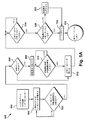
図5Aは、始動シーケンス306を図示し、図5B〜5Gは、機械50が始動シーケンスを実行する際の構成要素の状態を図示する。機械50が、アイドルシーケンス304から始動シーケンス306へ変えられるとき420(図4A)、機械50は、膨張および密閉されている材料の種類を識別する500。例えば、本機械は、材料がピロー型材料(例えば、図1参照)またはラップ型材料(例えば、米国特許第号D633792および第D630945号参照)であると判定してもよい。本機械はまた、このステップで膜10が作製される材料のサイズおよび種類を判定してもよい。
FIG. 5A illustrates a
始動シーケンス304では、加熱された密閉要素64が、ステップ502および504で、温度制御配列165によってアイドル温度から密閉温度まで上昇させられる(密閉温度がアイドル温度よりも高いとき)。ステップ506では、材料がラップ型材料である場合、膨張配列160が、アイドル出力または速度から膨張出力または速度まで上昇させられる508。アイドル出力または速度から膨張出力または速度までの上昇は、種々の異なる方法で制御されてもよい。例えば、膨張配列は、膜10の中の膨張圧力設定点に達するまで、膨張デバイスが速度設定点に達するまで、および/または膨張デバイスが速度設定点に達した後に所定の期間が経過するまで、上昇させられてもよい。図5Aの実施例では、膨張デバイスは、膨張デバイスが速度設定点に達した後に所定の期間にわたって、ラップ型材料を事前充填する510。
In the start-up
例示的実施形態では、本機械は、ステップ512および514で、加熱された密閉要素64を閉じる(図5G参照)。パウチ型材料は、加熱された密閉要素64が膜の上で閉じるときに、アイドル出力または速度で、膨張配列160の動作によって実質的に事前膨張させられる。同様に、ラップ型材料は、膨張配列160による膨張出力までの上昇によって、実質的に事前膨張させられる。このようにして、使用されている材料の種類にかかわらず、機械の起動時に、材料がほとんど、または全く無駄にされない。つまり、機械50の中へ送給される第1のパウチ26は、膨張させられていないか、または十分に膨張せられていない状態にあるのではなく、膨張および密閉される。
In the exemplary embodiment, the machine closes heated sealing
例示的実施形態では、本機械は、密閉要素が膜10の上で閉じた後に、膨張配列160が膨張速度または出力まですでに上昇させられているかどうかを判定する520。例えば、材料がパウチ型材料である場合、送風機は、加熱された密閉要素64が膜10の上で閉じられた後に、アイドル出力から膨張出力まで上昇する522。いったん加熱された密閉要素64が膜10の上で閉じられると、ベルト速度制御67が、ベルト70、270を始動させ524(図5Gの矢印を参照)、本機械が、密閉および膨張クッションを生産し始め、実行シーケンスに進む525。
In the exemplary embodiment, the machine determines 520 whether the
例示的実施形態では、密閉配列162、膨張配列160、および/または駆動ローラ68の制御は、相関している。例えば、密閉配列162、膨張配列160、および/または駆動ローラ68は、温度制御配列165、ベルト速度制御67、および/または送風機制御106のうちの1つ以上からの入力に基づいて制御される。密閉配列162、膨張配列160、および/または駆動ローラ68を相関させることによって、パウチの中の空気/圧力および/または膨張シール42の品質が、正確に制御されてもよい。
In the exemplary embodiment, the control of the sealing
例示的実施形態では、ベルト速度が、送風機制御106および/または温度制御配列165からのフィードバックに基づいて制御されてもよい。加熱された密閉要素64の温度が所定の設定点よりも低い場合、ベルト速度は、十分な熱が高品質のシールを形成するように膜に印加されていることを確実にするように、低減させられてもよい。同様に、加熱された密閉要素64の温度が所定の設定点よりも高い場合、ベルト速度は、過剰な熱が膜に印加されていないことを確実にし、それにより、高品質のシールが形成されていることを確実にするように、増加させられてもよい。膨張配列160の出力または速度が所定の設定点よりも低い場合、ベルト速度は、パウチ26が最適に充填されていることを確実にするように低減させられてもよい。例示的実施形態では、送風機出力あるいは速度および/または加熱された密閉要素64は、送風機出力または速度および加熱された密閉要素温度を所定の設定点に至らせるように、連続的に制御される。ベルトの速度は、特に、膨張配列および/または密閉要素が、それらの正常動作条件まで上昇させられるにつれて、シール品質およびパウチ充填を最適化するように、送風機制御106および/または温度制御配列165からのフィードバックに基づいて、連続的に更新されてもよい。
In the exemplary embodiment, belt speed may be controlled based on feedback from
例示的実施形態では、加熱された密閉要素64の温度は、送風機制御106および/またはベルト速度制御67からのフィードバックに基づいて制御されてもよい。ベルト速度が所定の設定点よりも低い場合、加熱された密閉要素64の温度は、過剰な熱が膜に印加されていないことを確実にし、かつ高品質のシールが形成されていることを確実にするように、低減させられてもよい。同様に、ベルト速度が所定の設定点よりも高い場合、加熱された密閉要素64の温度は、十分な熱が膜に印加されており、高品質のシールが形成されていることを確実にするように、増加させられてもよい。例示的実施形態では、送風機出力あるいは速度および/またはベルト速度制御67は、送風機出力または速度およびベルト速度を所定の設定点に至らせるように、連続的に制御される。加熱された密閉要素64の温度は、特に、膨張配列および/またはベルト速度が、それらの正常動作条件まで上昇させられるにつれて、シール品質およびパウチ充填を最適化するように、送風機制御106および/またはベルト速度からのフィードバックに基づいて、連続的に更新されてもよい。
In the exemplary embodiment, the temperature of the
例示的実施形態では、膨張配列160は、ベルト速度制御67および/または温度制御配列165からのフィードバックに基づいて制御されてもよい。加熱された密閉要素64の温度が所定の設定点よりも低い場合、送風機出力または速度は、空気充填クッションの適正な膨張および密閉を確保するように変更されてもよい。ベルト速度が所定の設定点よりも低い場合、送風機出力または速度は、空気充填クッションの適正な膨張および密閉を確保するように変更されてもよい。例示的実施形態では、ベルト速度および/または発熱体温度は、ベルト速度および/または発熱体温度を所定の設定点に至らせるように、連続的に制御される。送風機速度または出力は、特に、ベルト速度および/または密閉温度が、それらの正常動作条件まで上昇させられるにつれて、シール品質およびパウチ充填を最適化するように、ベルト速度制御67および/または温度制御配列165からのフィードバックに基づいて、連続的に更新されてもよい。
In the exemplary embodiment,
1つの例示的実施形態では、密閉配列162の温度は、膨張制御およびベルト制御からのフィードバックとは無関係である。この実施形態では、ベルト速度は、密閉配列162からのフィードバックのみに基づいて制御されてもよい。同様に、この実施形態では、膨張配列160は、密閉配列162からのフィードバックのみに基づいて制御されてもよい。例示的実施形態では、機械50は、密閉配列162を温度設定点に至らせ、かつ温度を設定点で保持する、制御ループでプログラムされる。この制御ループの実行中に、密閉配列の現在の温度が監視され、ベルト速度および膨張配列160を制御するために使用される。
In one exemplary embodiment, the temperature of the sealed
図6は、密閉配列162、膨張配列160、および/または駆動ローラ68の制御が相関している、実行シーケンス308の例示的実施形態を図示する。密閉配列162、膨張配列160、および/または駆動ローラ68の制御は、多種多様の異なる方法で相関することができ、図6は、多くの可能性のうちの1つを図示することを理解されたい。図6では、加熱デバイスの温度に対するベルト速度および膨張デバイス速度または出力の関係が設定される600。ベルト速度および膨張デバイス速度または出力は、加熱された密閉要素64の現在の温度に基づいて設定される602。随意的なステップ604では、加熱された密閉要素64の設定点および/または膨張配列160の設定点が(例えば、ユーザ入力により)変化した場合、更新された設定点が読み出され606、加熱デバイスの温度に対するベルト速度および膨張デバイス速度または出力の関係がリセットされる600。加熱された密閉要素64の設定点および/または膨張配列160の設定点が変化していない場合、シーケンスは、加熱された密閉要素64が温度設定点に達したかどうかを確認するようにチェックする608。加熱された密閉要素64が温度設定点に達していない場合、ベルト速度および膨張デバイス速度または出力は、加熱された密閉要素64の現在の温度に基づいて更新される602。このプロセスは、加熱された密閉要素64が温度設定点に達するまで繰り返される。
FIG. 6 illustrates an exemplary embodiment of an
いったん加熱された密閉要素64が温度設定になり610、ベルト速度および膨張デバイス出力が、対応する設定点になると612、加熱デバイスの温度に対するベルト速度と膨張デバイス速度または出力との間の関係は、随意に、機械が所定の期間にわたって停止されるまで、あるいはベルト速度および/または膨張デバイス出力の更新をトリガする事象が検出されるまで、無視されてもよい614。この時点で、機械50は、全速度または最適な速度で作動しており615、膨張設定が変化する616、熱設定が変化する618、または機械が停止される620まで、そのように作動し続ける。膨張デバイス設定が変化するとき、膨張デバイス速度または出力は、新しい設定に基づいて増加または減少させられる622。温度設定が変化するとき、加熱デバイス温度設定点は、新しい設定に基づいて増加または減少させられる624。機械が停止されるとき、シーケンスは、停止シーケンス310へ進む626。
Once the
図7Aは、例示的な停止シーケンスを図示し、図7B〜7Dは、停止シーケンス中の機械50の構成要素の状態の実施例を図示する。停止シーケンス310では、ベルト速度制御67が、ベルト70、270(図7D)を停止させる700。随意的なステップ702では、材料がピロー型材料である場合、膨張配列160がブレーキをかけられる703。ステップ704では、シーケンスが、ベルト70、270が停止させられていることを確認する。いったんベルト70、270が停止させられると、機械が密閉要素64を開く706。随意的なステップ708では、材料がラップ型材料である場合、シーケンスが、所定の期間が経過することを可能にし710、次いで、膨張配列160がブレーキをかけられる712。ステップ714では、シーケンスが、ベルト70、270および膨張配列160の両方が停止させられることを確認し716、シーケンスが、アイドルシーケンス304または停止状態302に戻る。
FIG. 7A illustrates an exemplary stop sequence, and FIGS. 7B-7D illustrate an example of the state of the components of the
機械50は、多種多様の異なる形態を成してもよい。図8〜25は、機械50の1つの非限定的な例示的実施形態を詳細に図示する。図8〜25によって図示される実施例では、機械50は、膨張配列960(図12および13参照)と、密閉配列962(図15参照)と、締付配列910(図18参照)と、膜分離デバイス958(図13参照)と、膜引張デバイス875(図12参照)とを含む。図8は、密閉配列962および締付配列910を覆って配置されたカバー802を伴う機械50を図示する。図8〜10は、カバーが除去された機械50を図示する。
図8〜10を参照すると、膜10は、供給部から、一対の細長い横方向に延在するガイドローラ854へ、およびそれらの周囲に送られる。次いで、膜10は、縦方向に延在するガイドピン856へ送られる。ガイドピン856は、膜10の膨張側縁20と横シール22との間に配置される。ガイドピン856は、機械を通して引かれるにつれて膜を整合させる。膜10は、膜引張デバイス875を通してガイドピン856に沿って送られる。
Referring to FIGS. 8-10, the
膜引張デバイス875は、膜が機械50を通して引かれるにつれて(図12参照)引っ張られた状態で膜10を保つ(図12B参照)。密閉配列962の中で引っ張られた状態で膜10を保つことにより、しわがポケット23に形成されることを防止する。引張デバイスは、多種多様の異なる形態を成すことができる。張力を膜10に印加する任意の配列を使用することができる。図12Aおよび12Bを参照すると、図示した実施形態では、膜引張デバイス875は、ローラ877と、バネ荷重枢動アーム879と、棚部材881とを含む。棚部材881は、膜10の進行路に対して固定される。図示した棚部材881は、実質的に水平の部分883と、実質的に水平の部分883から鈍角で上向きに延在する、上向きに延在する部分885とを含む。
The
実質的に水平の部分883および上向きに延在する部分885は、種々の異なる形態を成すことができる。図12Aでは、ガイドピン856の中心線1252(最上部と底部との間の中間点)が描写される。例示的実施形態では、実質的に水平の部分883の上面1260は、中心線1252よりも低い。図12Aによって図示される実施例では、実質的に水平の部分883の上面1260は、ガイドピン856の底部1262よりも低い。図12Aでは、上向きに延在する部分885の頂面または最上面に接する水平線1250が描写される。例示的実施形態では、頂面または最上面1250は、ポケット23のミシン目が破れるほど引っ張られないが、ガイドピン856に対して引っ張られた状態でポケット23を保つように位置付けられる。ガイドピン856に対して引っ張られた状態で膜10のポケット23を引くことによって、膜が密閉配列162を通過するにつれて、膜のしわが排除される。1つの例示的実施形態では、最上面1250は、ガイドピン856の中心線1252に、またはそれより上側に位置付けられる。例えば、最上面1250は、中心線より上側で距離Dに位置付けられてもよい。距離Dは、0.250インチ以下、0.218インチ以下、0.187インチ以下、0.156インチ以下、0.125インチ以下、0.093インチ以下、0.062インチ以下、または0.031インチ以下であってもよい。
The substantially
図12Bを参照すると、バネ荷重枢動アーム879が、枢動部887において機械50に枢動可能に載置される。バネ889が、枢動アームの第1の端部に、および機械50に取り付けられる。ローラ877は、バネ荷重枢動アーム879の第2の端部に回転可能に取り付けられる。バネ889は、実質的に水平の部分883および上向きに延在する部分885の交差点で棚部材881に対してローラ877を押勢する。ローラ877、バネ荷重枢動アーム879、および/またはバネ889は、膜に摩擦係合する任意の配列と置換できることが容易に明白となるはずである。摩擦力は、膜が密閉配列162を通過するにつれて引っ張られた状態で膜10を保持するように選択されるが、摩擦力は、膜10を引き裂かせるほど十分大きくない。1つの例示的実施形態では、ローラ877と棚部材881との間に印加される力は、約7lbsまたは7lbs等の5lbsから10lbsの間である。ローラ877と棚部材881との間の接触域の幅もまた、膜10に印加される摩擦力に影響を及ぼす。1つの例示的実施形態では、ローラ877と棚部材881との間の接触域の幅は、0.062から0.375インチの間、0.093から0.250インチの間、0.125から0.187インチの間、約0.140インチ、または0.140インチである。
Referring to FIG. 12B, a spring loaded
図12Bを参照すると、膜10は、ローラおよび棚部材が膜10の層14、16に摩擦係合するように、ローラ877と棚部材881との間に送られる。膜10は、ローラ877の下で、上方へ、および棚部材の上向きに延在する部分の上885で、次いで、密閉配列962の中へ通過する。膜10、ローラ877、および棚部材881の間の摩擦は、膜が密閉配列962を通して引かれるにつれて、引っ張られた状態で膜を保つ。
Referring to FIG. 12B, the
膨張配列960は、多種多様の異なる形態を成すことができる。図12および13を参照すると、図示した実施形態では、膨張配列960は、中空の縦方向に延在するガイドピン856と、送風機または他の圧力下の空気源または圧力下の他の流体に流体接続するための入口開口部857とを含む。図示したガイドピン856は、複数の膨張開口部102(図12参照)を含む。膨張開口部102は、多種多様の異なる形態を成すことができる。図示した実施形態では、ガイドピン856は、第1の比較的大きい開口部1200と、複数のより小さい開口部1202とを含む。図示した開口部1200は、半円形の端部を伴うスロットである。図示したより小さい開口部1202は、形状が円形である。送風機および送風機制御は、機械50の筐体1204(図8〜10)の中に配置される。
The
密閉配列962は、密閉した膨張エアクッション12を作成するように膨張シール42を形成する。密閉配列962は、多種多様の異なる形態を成すことができる。図15〜17を参照すると、密閉配列962は、加熱された密閉要素864、865と、熱密閉要素位置付けデバイス866と、駆動ローラ868と、アイドラローラ869と、密閉ベルト870とを含む。各ベルト870は、その各熱密閉要素864、865、駆動ローラ868、およびアイドラローラ869の周囲に配置される。各ベルト870は、その各駆動ローラ868によって駆動される。例示的実施形態では、駆動ローラ868およびベルト870の速度は、機械の筐体1204の中に配置されるベルト速度制御によって制御される。ベルト速度制御は、機械用の全体的なコントローラの一部であってもよく、またはベルト速度コントローラは、他のデバイスと連動する別個のデバイスであってもよい。ベルト870が熱密閉要素864、865を通して膜10を引くように、ベルト870は、相互に係合する。膜10が加熱された密閉要素864、865を通過するにつれて、膨張シール42が形成される。
The sealed
図21を参照すると、図示した実施例では、加熱された密閉要素864は、付勢アセンブリ2100によって加熱された密閉要素865に向かって付勢される。付勢アセンブリ2100は、多種多様の異なる形態を成すことができる。付勢配列は、比較的相互に向かって加熱された密閉要素864、865を付勢する、任意の配列であってもよい。図示した実施例では、付勢アセンブリ2100は、支持部材2101と、シャフト部材2102と、シャフト部材の周囲に配置されたバネ2104と、熱密閉要素864に接続された連結部材2106とを含む。シャフト部材2102の先頭2108が、支持部材2101の中の穴2114を通って延在するシャフト部材のシャフト部分2112を伴って、支持部材2101のカウンターボア2110中に配置される。シャフト部材2102は、カウンターボアの中で軸方向に自由に移動することができる。シャフト部分の端部は、連結部材2106に接続される。バネ2104は、連結部材2106および取り付けられた加熱された密閉要素864を下向きに押す。付勢アセンブリ2100は、ベルトが係合されたときはいつでも、加熱された密閉要素864、865が、ベルト870の間で膜10にしっかりと係合することを確実にする。
Referring to FIG. 21, in the illustrated embodiment,
加熱された密閉要素864は、多種多様の異なる形態を成すことができる。図21を参照すると、図示した実施例では、加熱された密閉要素864は、外側本体1600と、内部セラミック要素1602と、内部熱電対1604または内部セラミック要素1602の温度を測定するための他のデバイスとを含む。ポッティング材料または他の封入材料が、内部セラミック要素1602および内部熱電対1604を包囲する。例示的実施形態では、内部熱電対1604は、内部セラミック要素1602の上に直接配置される。
The
温度制御配列が、内部熱電対1604からのフィードバックに基づいて内部セラミック要素1602の温度を制御するために、内部熱電対1604および内部セラミック要素1602に連結される。熱電対によって測定される温度は、発熱体に印加される電力を調整し、それにより、発熱体の温度を制御するために使用される。温度制御配列は、機械の筐体1204の中に配置される。温度制御配列は、機械用の全体的なコントローラの一部であってもよく、または温度制御配列は、他のデバイスと連動する別個のデバイスであってもよい。
Temperature control sequences, in order to control the temperature inside the
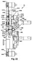
熱密閉要素位置付けデバイス866は、多種多様の異なる形態を成すことができる。図13、14、21、および22を参照すると、図示した実施例では、加熱された密閉要素864、865は、上部支持部材2101および下部支持部材2103に連結される。加熱された密閉要素864は、上記で説明されるように、付勢アセンブリ2100によって上部支持部材2101に連結される。下部加熱された密閉要素865は、下部支持部材2103に固定される。しかしながら、下部熱密閉要素は、任意の方式で下部支持部材2103に連結されてもよい。例えば、下部加熱された密閉要素865は、第2の付勢アセンブリによって下部支持部材2103に連結されてもよい。図示した実施形態では、熱密閉要素位置付けデバイス866は、2つの上部アクチュエータ1300、1302と、2つの下部アクチュエータ1304、1306とを備える。2つの上部アクチュエータ1300、1302はそれぞれ、上部支持部材2101および筐体1204等の機械50の固定された構成要素に動作可能に接続される。2つの下部アクチュエータ1304、1306はそれぞれ、下部支持部材2103および筐体1204等の機械50の固定された構成要素に動作可能に接続される。アクチュエータ1300、1302、1304、1306は、比較的相互に向かって、かつ相互から離して、上部および下部支持部材2101、2103、および連結された加熱された密閉要素864、865を移動させるように動作可能である。そのようなものとして、加熱された密閉要素864、865は、密閉ベルト870が、膜10に選択的に係合し、かつそれを係脱するように、膜10の進行路に対して位置付けられる。
The heat sealing
図24および25を参照すると、図示した上部および下部支持部材2101、2103は、シール冷却部分2401、2403を含む。シール冷却部分2401、2403は、ベルト870に係合し、加熱された密閉要素864、865の下流でシールの材料を圧縮する。シールの熱は、シールの材料を冷却するように、ベルト870を通して上部および下部支持部材2101、2103のシール冷却部分2401、2403の中へ伝達される。図示した上部および下部支持部材2101、2103は、随意的な穴2410を含む。穴2410は、上部および下部支持部材2101、2103の表面積を増加させて、ヒートシンクとしてのそれらの有効性を増加させ、それらの重量を低減させる。上部および下部支持部材2101、2103は、多種多様の異なる材料から作製することができる。例示的実施形態では、支持部材は、アルミニウムまたは銅等の熱伝導性材料から作製される。
Referring to FIGS. 24 and 25, the illustrated upper and
締付配列910は、予備形成膜の上および底層14、16をともに挟持するように位置付けられる。締付配列910は、多種多様の異なる形態を成すことができる。図18および19を参照すると、締付配列910は、駆動ローラ1068と、アイドラローラ1069と、バネ荷重締付アセンブリ1800と、下部支持部材2103の締付部分1802と、一対の駆動ベルト1070とを含む。下部支持部材2103の図示した締付部分1802は、支持面1810または溝および穴縁1812を含む。支持面1810または溝の幅は、ベルト1070の幅に対応する。支持面1810または溝は、下部ベルト1070を支持し、穴縁1812は、ベルトまたは支持面を保持する。
The clamping
図24および25を参照すると、各バネ荷重締付アセンブリ1800は、締付部材1900と、シャフト部材1902と、シャフト部材の周囲に配置されたバネ1904とを含む。締付部材1900、シャフト部材1902、およびバネは、支持部材1901に連結される。各締付部材1900は、バネ1904によって下部支持部材2103の締付部分1802に向かって付勢される。各シャフト部材1902の先頭1908が、支持部材1901の中の穴1914を通って延在するシャフト部材のシャフト部分1912を伴って、支持部材1901の上に配置される。シャフト部材1902は、カウンターボアの中で軸方向に自由に移動することができる。シャフト部分1912の端部は、締付部材1900に接続される。バネ1904は、締付部材1900を下向きに押す。バネ荷重締付アセンブリ1800は、ベルトが係合されたときはいつでも、ベルト1070が膜10にしっかりと係合することを確実にする。
Referring to FIGS. 24 and 25, each spring
各ベルト1070は、その各駆動ローラ1068およびアイドラローラ1069の周囲に配置される。各ベルト1070は、駆動ローラ868に取り付けられる、その各駆動ローラ1068によって駆動される。そのようなものとして、密閉ベルト870および挟持ベルト1070は、同期して駆動される。膜が加熱された密閉要素864、865を通って移動するにつれて、ベルト1070が、膜10を引き、かつ膜を挟持するように、ベルト1070は、相互に係合する。
Each
図示した実施形態では、締付配列910は、加熱された密閉要素864を位置付ける、同一の熱密閉要素位置付けデバイス866によって位置付けられる。締付配列910が、上部および下部支持部材2101、2103とともに移動するため、熱密閉要素位置付けデバイス866による上部および下部支持部材2101、2103の移動もまた、締付配列910を移動させる。熱密閉要素位置付けデバイス866は、膜10を選択的に握持および解放するように、締付配列910に連結される。これは、膜10が機械50に手動で搭載されることを可能にし、膜が機械から手動で除去されることを可能にし、および/または膜10の任意の送給失敗が取り除かれることを可能にする。
In the illustrated embodiment, the clamping
図13および14を参照すると、図示した膜分離デバイス958は、ガイドピン856に載置される。膜分離デバイス958は、縁1350を含む。縁1350は、ポケットを開き、膜10が機械を通過することを可能にするように、膜10に係合する。縁1350は、膜10の構成に応じて、鈍的な縁または鋭い縁であってもよい。例えば、膜10が、シール側縁18に、またはそれに沿って、ミシン目線を含むとき、縁1350は、鈍的な表面であってもよく、膨張側縁18が穿孔されないとき、縁は鋭くあり得る。図13を参照すると、図示した実施形態では、膜分離デバイス958は、進行路に沿って加熱された密閉要素864に位置付けられる。膜分離デバイス958は、パウチ26が密閉されているのと同時に、膜分離デバイスが膜のポケット23を開くように、熱密閉要素の後ろに位置付けられる。
Referring to FIGS. 13 and 14, the illustrated
本発明の種々の発明の側面、概念、および特徴が、例示的実施形態において組み合わせで具現化されるように、本明細書で説明および例証され得るが、これらの種々の側面、概念、および特徴は、個別に、またはそれらの種々の組み合わせおよび副次組み合わせでのいずれかで、多くの代替実施形態で使用されてもよい。本明細書で明示的に除外されない限り、全てのそのような組み合わせおよび副次組み合わせは、本発明の範囲内にあることを目的とする。なおもさらに、代替的な材料、構造、構成、方法、回路、デバイスおよび構成要素、ハードウェア、形態、適合、および機能に関する代替案等の、本発明の種々の側面、概念、および特徴に関する種々の代替実施形態が、本明細書で説明され得るが、そのような説明は、現在公知であろうと、後に開発されようと、利用可能な代替実施形態の完全または包括的リストとなることを目的としていない。当業者は、たとえそのような実施形態が本明細書で明示的に開示されていなくても、本発明の側面、概念、または特徴のうちの1つ以上を、本発明の範囲内の付加的な実施形態および用途に容易に導入してもよい。加えて、たとえ本発明のいくつかの特徴、概念、または側面が、好ましい配列または方法であるものとして本明細書で説明され得ても、そのような特徴は、明示的にそのように記述されない限り、そのような特徴が要求されるか、または必要であると示唆することを目的としていない。なおもさらに、例示的または代表的な値および範囲が、本開示の理解を支援するように含まれてもよいが、そのような値および範囲は、限定的な意味で解釈されるものではなく、明示的にそのように記述された場合のみ、臨界値または範囲となることを目的としている。また、種々の側面、特徴、および概念が、独創的であるか、または発明の一部を形成するものとして本明細書で明示的に識別される一方で、そのような識別は、包括的となることを目的としていないが、むしろ、そのようなものとして、または特定の発明の一部として明示的に識別されることなく、本明細書で完全に説明される発明の側面、概念、および特徴があってもよい。例示的な方法およびプロセスの説明は、全ての場合に必要とされるものとして全てのステップの包含に限定されず、また、ステップが提示される順序も、そのように明示的に記述されない限り、要求されるか、または必要であるものとして解釈されない。 Although the various inventive aspects, concepts and features of the present invention may be described and illustrated herein as embodied in combination in an exemplary embodiment, these various aspects, concepts and features May be used in many alternative embodiments, either individually or in various combinations and subcombinations thereof. Unless explicitly excluded herein, all such combinations and subcombinations are intended to be within the scope of the present invention. Still further, various aspects, concepts, and features of the present invention, such as alternative materials, structures, configurations, methods, circuits, devices and components, hardware, configurations, adaptations, and functional alternatives, etc. Alternative embodiments may be described herein, but such descriptions are intended to be a complete or comprehensive list of available alternative embodiments, whether now known or later developed. Not. Those skilled in the art will recognize that one or more of the aspects, concepts, or features of the present invention may be added within the scope of the present invention, even if such embodiments are not explicitly disclosed herein. May be easily introduced into various embodiments and applications. In addition, even though some features, concepts, or aspects of the invention may be described herein as being a preferred arrangement or method, such features are not explicitly described as such. In no way is it intended to suggest that such a feature is required or necessary. Still further, exemplary or representative values and ranges may be included to aid in understanding the present disclosure, but such values and ranges are not to be construed in a limiting sense. It is intended to be a critical value or range only if explicitly stated as such. Also, while various aspects, features and concepts are explicitly identified herein as being original or forming part of the invention, such identification is Rather than as such or explicitly identified as part of a particular invention, aspects, concepts and features of the invention fully described herein. There may be. The description of exemplary methods and processes is not limited to the inclusion of all steps as required in all cases, and the order in which the steps are presented is not explicitly stated as such. It is not construed as required or necessary.
本発明が、その実施形態の説明によって例証されている一方で、および実施形態が、かなり詳細に説明されている一方で、本発明の範囲をそのような詳細に制限すること、またはいかようにも限定することは、本出願人の意図ではない。付加的な利点および修正が、当業者に容易に明白となるであろう。例えば、構成要素の接続および相互配置の特定の場所を修正することができる。したがって、本発明は、その広範な側面で、示され、説明される、具体的詳細、代表的な装置、および例証的実施例に限定されない。したがって、本出願人の一般的発明概念の精神または範囲から逸脱することなく、そのような詳細から逸脱することができる。 While the invention has been illustrated by description of embodiments thereof, and embodiments have been described in considerable detail, the scope of the invention is limited to such details, or how It is not the intention of the present applicant to limit. Additional advantages and modifications will be readily apparent to those skilled in the art. For example, certain locations of component connections and interpositions can be modified. The invention in its broader aspects is therefore not limited to the specific details, representative apparatus, and illustrative embodiments shown and described. Accordingly, departures may be made from such details without departing from the spirit or scope of applicants' general inventive concept.
Claims (19)
前記機械は、
前記膜の進行路を画定するように、前記横シールと前記膨張縁との間に挿入するためのガイドピンと、
前記膜と摩擦係合するための引張デバイスであって、前記引張デバイスは、下流進行中に引っ張られた状態で膜を保持し、前記引張デバイスは、棚部材を含み、前記棚部材は、前記ガイドピンの中心線の下側の水平部分と、下流の上向きに角度を成す部分とを有し、前記水平部分の上面は、前記ガイドピンの中心線よりも低くに位置付けられており、前記下流の上向きに角度を成す部分の上面は、前記中心線よりも上側に位置付けられている、引張デバイスと、
前記予備形成パウチの膨張のための膨張配列と、
前記予備形成パウチを閉じて緩衝材ユニットを形成するように前記横シールと交差する、縦シールを提供するように位置付けられる、密閉配列であって、前記密閉配列は、少なくとも2つの密閉ベルトを有し、各ベルトが、駆動ローラによって動力供給され、前記膜の表面に係合し、前記膜の両側に位置付けられた密閉要素を通して前記膜を引くように位置付けられる、密閉配列と、
前記密閉要素を通した進行中に、前記膜の2つの層を挟持するように位置付けられる、締付配列であって、前記締付配列は、少なくとも2つの挟持ベルトを有し、各ベルトが、駆動ローラによって動力供給され、前記膜の表面に係合し、前記密閉要素を通して前記膜を引き、かつ前記膜を挟持するように位置付けられ、前記2つの密閉ベルトは、前記2つの挟持ベルトと前記膨張縁との間に配置される、締付配列と
を備え、
前記少なくとも2つの密閉ベルトおよび前記少なくとも2つの挟持ベルトは、同期して駆動される、機械。 A machine for converting a preformed pouch membrane into an inflated cushioning unit, said pouch being defined by a transverse seal extending from a remote edge to within a predetermined distance from the inflating edge;
The machine is
A guide pin for insertion between the transverse seal and the expansion edge to define a path of travel of the membrane;
A tensioning device for frictional engagement with the membrane , the tensioning device holding the membrane in a tensioned state during downstream progression , the tensioning device including a shelf member, and the shelf member comprising the shelf member A lower horizontal portion of the center line of the guide pin and a downstream upwardly angled portion, and the upper surface of the horizontal portion is positioned lower than the center line of the guide pin; A tensioning device , wherein the upper surface of the upward angled portion is positioned above the centerline ;
An inflation arrangement for inflation of the preformed pouch;
A sealing arrangement positioned to provide a longitudinal seal that intersects the transverse seal to close the preformed pouch to form a cushioning unit, the sealing arrangement having at least two sealing belts. A sealing arrangement in which each belt is powered by a drive roller, engages the surface of the membrane and is positioned to pull the membrane through sealing elements positioned on opposite sides of the membrane;
A clamping arrangement positioned to clamp two layers of the membrane during progression through the sealing element, the clamping arrangement having at least two clamping belts, each belt comprising: Powered by a drive roller, engages the surface of the membrane, pulls the membrane through the sealing element, and is positioned to sandwich the membrane, the two sealing belts include the two clamping belts and the A clamping arrangement arranged between the expansion edge and
The machine, wherein the at least two sealing belts and the at least two clamping belts are driven synchronously.
前記機械は、
前記膜の進行路を画定するように、前記横シールと前記膨張縁との間に挿入するためのガイドピンと、
前記膜と摩擦係合するための引張デバイスであって、前記引張デバイスは、棚部材と、前記機械に載置された枢動可能なアームとを有し、前記棚部材は、水平部分と、下流の上向きに角度を成す部分とを有し、前記水平部分の上面は、前記ガイドピンの中心線よりも低くに位置付けられており、前記下流の上向きに角度を成す部分の上面は、前記中心線よりも上側に位置付けられており、前記アームの一方の端がバネに取り付けられ、ローラが前記アームの他方の端に回転可能に取り付けられる、引張デバイスと、
前記予備形成パウチの膨張のための膨張配列と、
前記予備形成パウチを閉じて緩衝材ユニットを形成するように前記横シールと交差する、縦シールを提供するように位置付けられる、密閉配列であって、前記密閉配列は、少なくとも2つの密閉ベルトを有し、各ベルトが、駆動ローラによって動力供給され、前記膜の表面に係合し、前記膜の両側に位置付けられた密閉要素を通して前記膜を引くように位置付けられる、密閉配列と、
前記密閉要素を通した進行中に、前記膜の2つの層を挟持するように位置付けられる、締付配列と
を備え、
前記引張デバイスは、前記ローラによる前記膜の係合によって、下流進行中に引っ張られた状態で前記膜を保持する、機械。 A machine for converting a preformed pouch membrane into an inflated cushioning unit, said pouch being defined by a transverse seal extending from a remote edge to within a predetermined distance from the inflating edge;
The machine is
A guide pin for insertion between the transverse seal and the expansion edge to define a path of travel of the membrane;
A tensioning device for frictional engagement with the membrane, the tensioning device comprising a shelf member and a pivotable arm mounted on the machine, the shelf member comprising a horizontal portion; A downstream upward angled portion, wherein the upper surface of the horizontal portion is positioned lower than the center line of the guide pin, and the upper surface of the downstream upward angled portion is the center A tensioning device positioned above the line, wherein one end of the arm is attached to a spring and a roller is rotatably attached to the other end of the arm;
An inflation arrangement for inflation of the preformed pouch;
A sealing arrangement positioned to provide a longitudinal seal that intersects the transverse seal to close the preformed pouch to form a cushioning unit, the sealing arrangement having at least two sealing belts. A sealing arrangement in which each belt is powered by a drive roller, engages the surface of the membrane and is positioned to pull the membrane through sealing elements positioned on opposite sides of the membrane;
A clamping arrangement positioned so as to sandwich the two layers of the membrane during progression through the sealing element;
The tensioning device holds the membrane in a pulled state during downstream travel by engagement of the membrane by the roller.
前記機械は、前記膜と摩擦係合するための引張デバイスを備え、
前記引張デバイスは、棚部材と、前記機械に載置された枢動可能なアームとを有し、前記棚部材は、水平部分と、下流の上向きに角度を成す部分とを有し、前記水平部分の上面は、ガイドピンの中心線よりも低くに位置付けられており、前記下流の上向きに角度を成す部分の上面は、前記中心線よりも上側に位置付けられており、前記アームの一方の端がバネに取り付けられ、ローラが前記アームの他方の端に回転可能に取り付けられ、
前記ローラは、下流進行中に引っ張られた状態で前記膜を保持するように、前記棚部材の前記水平部分に対して、および前記棚部材の前記上向きに角度を成す部分に対して前記膜を押勢する、機械。 A machine for converting a preformed pouch membrane into an inflated cushioning unit, said pouch being defined by a transverse seal extending from a remote edge to within a predetermined distance from the inflating edge;
The machine comprises a tensioning device for frictional engagement with the membrane;
The tensioning device has a shelf member and a pivotable arm mounted on the machine, the shelf member having a horizontal portion and a downstream angled portion, the horizontal The top surface of the portion is positioned lower than the center line of the guide pin, and the top surface of the downstream angled portion is positioned above the center line , and one end of the arm Is attached to the spring, and a roller is rotatably attached to the other end of the arm,
The roller holds the membrane against the horizontal portion of the shelf member and the upwardly angled portion of the shelf member so as to hold the membrane in a pulled state while traveling downstream. Pushing machine.
The machine of claim 17, wherein the membrane travels under the roller, upwards, and on the upwardly angled portion of the shelf member, and directly downstream to the sealed arrangement.
Applications Claiming Priority (3)
| Application Number | Priority Date | Filing Date | Title |
|---|---|---|---|
| US201161505261P | 2011-07-07 | 2011-07-07 | |
| US61/505,261 | 2011-07-07 | ||
| PCT/US2012/045718 WO2013006779A1 (en) | 2011-07-07 | 2012-07-06 | Air cushion inflation machine |
Related Child Applications (1)
| Application Number | Title | Priority Date | Filing Date |
|---|---|---|---|
| JP2017091361A Division JP2017128396A (en) | 2011-07-07 | 2017-05-01 | Air cushion inflation machine |
Publications (3)
| Publication Number | Publication Date |
|---|---|
| JP2014518185A JP2014518185A (en) | 2014-07-28 |
| JP2014518185A5 JP2014518185A5 (en) | 2015-08-20 |
| JP6140695B2 true JP6140695B2 (en) | 2017-05-31 |
Family
ID=47437463
Family Applications (3)
| Application Number | Title | Priority Date | Filing Date |
|---|---|---|---|
| JP2014519062A Expired - Fee Related JP6140695B2 (en) | 2011-07-07 | 2012-07-06 | Air cushion inflating machine |
| JP2017091361A Withdrawn JP2017128396A (en) | 2011-07-07 | 2017-05-01 | Air cushion inflation machine |
| JP2019035869A Pending JP2019108171A (en) | 2011-07-07 | 2019-02-28 | Air cushion expansion machine |
Family Applications After (2)
| Application Number | Title | Priority Date | Filing Date |
|---|---|---|---|
| JP2017091361A Withdrawn JP2017128396A (en) | 2011-07-07 | 2017-05-01 | Air cushion inflation machine |
| JP2019035869A Pending JP2019108171A (en) | 2011-07-07 | 2019-02-28 | Air cushion expansion machine |
Country Status (14)
| Country | Link |
|---|---|
| US (3) | US9266300B2 (en) |
| EP (2) | EP2729369B1 (en) |
| JP (3) | JP6140695B2 (en) |
| KR (1) | KR20140053165A (en) |
| AU (1) | AU2012278849B2 (en) |
| BR (1) | BR112014000258A2 (en) |
| CA (1) | CA2841365A1 (en) |
| CL (1) | CL2014000021A1 (en) |
| CO (1) | CO6940390A2 (en) |
| ES (1) | ES2617330T3 (en) |
| HU (1) | HUE031928T2 (en) |
| MX (2) | MX353115B (en) |
| PL (1) | PL2729369T3 (en) |
| WO (1) | WO2013006779A1 (en) |
Families Citing this family (28)
| Publication number | Priority date | Publication date | Assignee | Title |
|---|---|---|---|---|
| WO2005118408A2 (en) * | 2004-06-01 | 2005-12-15 | Automated Packaging Systems, Inc. | Web and method for making fluid filled units |
| US7897219B2 (en) | 2004-06-01 | 2011-03-01 | Automated Packaging Systems, Inc. | Web and method for making fluid filled units |
| EP2209614B1 (en) | 2007-10-31 | 2015-08-19 | Automated Packaging Systems, Inc. | Web and method for making fluid filled units |
| US9205622B2 (en) | 2009-02-27 | 2015-12-08 | Automated Packaging Systems, Inc. | Web and method for making fluid filled units |
| MX353115B (en) | 2011-07-07 | 2017-12-20 | Automated Packaging Systems Inc | Air cushion inflation machine. |
| EP2969521B1 (en) | 2013-03-15 | 2022-11-30 | Automated Packaging Systems, Inc. | On-demand inflatable packaging |
| AU2014318893B2 (en) * | 2013-09-10 | 2018-01-18 | Automated Packaging Systems, Inc. | Web for making fluid filled units |
| WO2015077551A1 (en) * | 2013-11-21 | 2015-05-28 | Automated Packaging Systems, Inc. | Air cushion inflation machine |
| US20150151864A1 (en) * | 2013-12-02 | 2015-06-04 | Stan Lin | Air Packaging Machine |
| MX365844B (en) * | 2014-02-24 | 2019-06-17 | Pregis Innovative Packaging Llc | Recipe controlled device for making packaging materials. |
| US11858712B2 (en) | 2014-04-14 | 2024-01-02 | Pregis Innovative Packaging Llc | Flexible structure with perforation-free inflation channel |
| US10081457B2 (en) | 2014-11-10 | 2018-09-25 | Pregis Innovative Packaging Llc | Inflatable packaging with apertures |
| EP3442871B1 (en) * | 2016-04-11 | 2020-12-23 | Automated Packaging Systems, Inc. | Air cushion inflation machine |
| CN205836096U (en) * | 2016-07-01 | 2016-12-28 | 杭州丙甲科技有限公司 | Buffer air cushion machine |
| US10661509B2 (en) * | 2017-09-22 | 2020-05-26 | Arpac, Llc | Film edge sealing device |
| US10717583B2 (en) | 2017-09-29 | 2020-07-21 | Amazon Technologies, Inc. | Packaging products and associated material |
| WO2019161118A1 (en) | 2018-02-14 | 2019-08-22 | Pregis Innovative Packaging Llc | Devices for the formation of protective packaging |
| JP7252964B2 (en) | 2018-02-14 | 2023-04-05 | プレジス イノベーティブ パッケージング エルエルシー | Web expansion and sealing device |
| WO2019161103A1 (en) * | 2018-02-14 | 2019-08-22 | Pregis Innovative Packaging Llc | Devices for manufacturing inflatable chushions to be used as packaging material |
| MX2020008547A (en) | 2018-02-14 | 2021-01-08 | Pregis Innovative Packaging Llc | Devices for manufacturing inflatable cushions to be used as packaging material. |
| CN112533752B (en) | 2018-02-14 | 2023-01-06 | 普里吉斯创新包装有限责任公司 | Heating device for heating and sealing system |
| CN108312641A (en) * | 2018-03-05 | 2018-07-24 | 厦门艾美森新材料科技股份有限公司 | A kind of wound membrane oral area obturating system and inflation heat sealing machine |
| US10967995B1 (en) * | 2018-03-13 | 2021-04-06 | Amazon Technologies, Inc. | Inflatable packaging materials, automated packaging systems, and related methods |
| US10793333B2 (en) | 2018-08-14 | 2020-10-06 | Pregis Innovative Packaging Llc | Inflatable packaging with offset tear initiation features |
| US11084637B1 (en) | 2018-09-28 | 2021-08-10 | Amazon Technologies, Inc. | Cushioned packaging materials, cushioned packages, and related methods |
| US11130620B1 (en) | 2018-09-28 | 2021-09-28 | Amazon Technologies, Inc. | Cushioned packaging materials, cushioned packages, and related methods |
| WO2020072727A1 (en) | 2018-10-04 | 2020-04-09 | Automated Packaging Systems, Llc | Air cushion inflation machine |
| DE102018009733A1 (en) * | 2018-12-11 | 2020-06-18 | Sprick Gmbh Bielefelder Papier- Und Wellpappenwerke & Co. | Device with an electric motor for providing packaging material and method for operating a packaging material supply device |
Family Cites Families (277)
| Publication number | Priority date | Publication date | Assignee | Title |
|---|---|---|---|---|
| US2153214A (en) * | 1936-10-03 | 1939-04-04 | Warner Bros | Pressure pad |
| US2379935A (en) | 1941-10-08 | 1945-07-10 | Mayer & Co Inc O | Packaging method |
| US3033257A (en) | 1957-08-21 | 1962-05-08 | H G Weber And Company Inc | Bag forming tube and method of forming and accumulating the same |
| NL281183A (en) | 1962-07-19 | |||
| US3254828A (en) | 1963-12-18 | 1966-06-07 | Automated Packaging Corp | Flexible container strips |
| US3405020A (en) | 1963-12-26 | 1968-10-08 | Sealed Air Corp | Method and apparatus for the manufacture of plastic laminates and cellular materials |
| US3298156A (en) | 1964-01-07 | 1967-01-17 | Automated Packaging Corp | Method and apparatus for packaging |
| US3254820A (en) | 1964-06-15 | 1966-06-07 | Du Pont | Shock absorbing system for yarn delivery apparatus |
| DE1225537B (en) | 1964-10-30 | 1966-09-22 | Dohmeier & Strothotte K G | Process and device for the continuous production of bags filled with large pieces of bulk goods |
| US3389534A (en) | 1965-09-16 | 1968-06-25 | John M. Pendleton | Machine for making cushioning packaging material or the like |
| US3414140A (en) | 1966-08-01 | 1968-12-03 | Interlake Steel Corp | Dunnage |
| US3358823A (en) | 1967-01-16 | 1967-12-19 | Allen D Paxton | Gusset bottom bags in roll form and method of making same |
| US3477196A (en) | 1967-04-27 | 1969-11-11 | Automated Packaging Corp | Mechanism for automatically feeding,loading,and sealing bags |
| US3462027A (en) | 1967-08-14 | 1969-08-19 | Edmund C Puckhaber | Dunnage device |
| US3456867A (en) | 1967-11-03 | 1969-07-22 | Dow Chemical Co | Bag assemblage |
| US3575757A (en) | 1967-12-08 | 1971-04-20 | Reinforced Air Corp | Process for making inflated articles |
| US3559874A (en) | 1968-05-08 | 1971-02-02 | Dow Chemical Co | Series bag construction |
| US3616155A (en) | 1968-06-26 | 1971-10-26 | Sealed Air Corp | Cellular laminate made from two thermoplastic sheets having polyvinylidene chloride coatings on facing sides of the sheets |
| US3523055A (en) | 1968-08-19 | 1970-08-04 | Jerome H Lemelson | Composite material,apparatus and method for producing same |
| US3577305A (en) | 1968-08-22 | 1971-05-04 | Theodore G Hines | Thermal and air shock insulating structure |
| US3660189A (en) | 1969-04-28 | 1972-05-02 | Constantine T Troy | Closed cell structure and methods and apparatus for its manufacture |
| US3575781A (en) | 1969-05-16 | 1971-04-20 | Stauffer Hoechst Polymer Corp | Plastic film wrapping material |
| BE754395A (en) | 1969-08-04 | 1971-02-04 | Basf Ag | METHOD AND DEVICE FOR MAKING OR CLOSING BAGS BY WELDING PORTIONS OF THERMOPLASTIC SHEATH |
| US3597895A (en) | 1969-09-08 | 1971-08-10 | Linvure Co Inc The | Packaging method and machine |
| US3650877A (en) | 1969-10-06 | 1972-03-21 | Arpax Co | Cushioning dunnage product |
| US3667593A (en) | 1970-03-30 | 1972-06-06 | John M Pendleton | Flowable dunnage apparatus and method of packaging with flowable and compliable inflated dunnage material |
| US3618286A (en) | 1970-06-08 | 1971-11-09 | Hercules Membrino | Bag filling sealing and separating system |
| US3837990A (en) | 1970-06-19 | 1974-09-24 | Connell R Mc | Reinforced cushioning material |
| US3817017A (en) | 1970-10-13 | 1974-06-18 | O Titchenal | Bag construction and method for filling the same |
| US3802974A (en) | 1970-12-01 | 1974-04-09 | L Emmel | Method and apparatus for insulating electrically conductive elements |
| ZA717126B (en) | 1971-03-04 | 1972-08-30 | Sealed Air Corp | Protective containers and methods of making the same |
| US3730240A (en) | 1971-03-16 | 1973-05-01 | Metatronics Manuf Corp | Inflatable insulation for packaging |
| US3744211A (en) | 1971-04-09 | 1973-07-10 | Dow Chemical Co | Automatic bag filling method |
| US3699746A (en) | 1971-04-09 | 1972-10-24 | Basic Packaging Systems Inc | Apparatus for filling a chain of connected bag elements |
| US3837991A (en) | 1971-05-03 | 1974-09-24 | Kimberly Clark Co | Plastic cushioning reinforced material |
| US3696580A (en) | 1971-05-17 | 1972-10-10 | Joseph M Saltzer Sr | Shrink film packaging method |
| US3791573A (en) | 1971-11-15 | 1974-02-12 | Basic Packaging Sys Inc | Bag construction |
| US3795163A (en) | 1971-12-16 | 1974-03-05 | Dow Chemical Co | Method of selectively cutting and perforating superposed panels of material |
| US3817803A (en) | 1972-06-19 | 1974-06-18 | Fmc Corp | Method of making a cellular cushioning structure |
| US3813845A (en) | 1972-06-23 | 1974-06-04 | Gen Films Inc | Filling and sealing system |
| US3941306A (en) | 1972-06-23 | 1976-03-02 | Weikert Roy J | System of interconnected, sealed and unsealed bags |
| US4014154A (en) | 1973-02-28 | 1977-03-29 | Automated Packaging Systems, Inc. | Packaging method and apparatus |
| US3808981A (en) | 1973-03-02 | 1974-05-07 | Interlake Inc | Disposable inflatable dunnage |
| NL172307C (en) | 1973-09-29 | 1983-08-16 | Wavin Bv | DEVICE FOR APPLYING CROSS-PERFORATION LINES IN A COURSE. |
| US4011798A (en) | 1973-11-29 | 1977-03-15 | Packaging Industries, Inc. | Method of making shipping bag |
| BE822385A (en) | 1973-11-29 | 1975-05-20 | REFILL SHIPPING BAG AND MANUFACTURING PROCESS | |
| US4021283A (en) | 1974-01-24 | 1977-05-03 | Weikert Roy J | Method of making aseptic packaging |
| US3938298A (en) | 1974-05-20 | 1976-02-17 | Minnesota Mining And Manufacturing Company | System for inflation and sealing of air cushions |
| US3939995A (en) | 1974-11-01 | 1976-02-24 | International Paper Company | Valve placement in a multi-ply, inflatable bag |
| US4096306A (en) | 1975-12-24 | 1978-06-20 | Minnesota Mining And Manufacturing Company | Strip material used in forming air inflated cushioning material |
| US4017351A (en) | 1975-12-24 | 1977-04-12 | Minnesota Mining And Manufacturing Company | System and device for inflating and sealing air inflated cushioning material |
| US4169002A (en) | 1975-12-24 | 1979-09-25 | Minnesota Mining And Manufacturing Company | Method for forming air inflated cushioning material |
| US4044693A (en) | 1976-03-12 | 1977-08-30 | Guardpack, Incorporated | Inflatable dunnage with tie-downs |
| US4040526A (en) | 1976-03-26 | 1977-08-09 | International Paper Company | Dunnage bag |
| US4076872A (en) | 1977-03-16 | 1978-02-28 | Stephen Lewicki | Inflatable cellular assemblies of plastic material |
| US4102364A (en) | 1977-07-29 | 1978-07-25 | Signode Corporation | Method of dunnage bag inflation |
| US4146069A (en) | 1977-07-29 | 1979-03-27 | Signode Corporation | Apparatus for rapidly inflating and pressurizing a dunnage bag |
| US4103471A (en) | 1977-09-01 | 1978-08-01 | International Paper Company | Atmosphere exchanging and bag sealing machine and method |
| US4214024A (en) | 1977-09-09 | 1980-07-22 | Monarch Marking Systems, Inc. | Composite label web and method of making same |
| AT377427B (en) | 1978-06-26 | 1985-03-25 | Hamann Klaus Jochen | DEVICE FOR SOLVABLE HOLDING OF SMALL PARTS, IN PARTICULAR TOOLS |
| US4201029A (en) | 1978-08-14 | 1980-05-06 | Automated Packaging Systems, Inc. | Method and apparatus for packaging |
| DE2851894A1 (en) | 1978-11-30 | 1980-06-12 | Agfa Gevaert Ag | DEVICE FOR SEPARATING PRE-PERFORATED TAPES, PREFERABLY CONTINUOUS BAGS |
| JPS55163105A (en) * | 1979-06-05 | 1980-12-18 | Tokyo Kikaika Kogyo Kk | Seallup system for packing device |
| US4245796A (en) * | 1979-06-15 | 1981-01-20 | Chromalloy American Corporation | System for handling flexible sheet rolls |
| US4314865A (en) | 1979-09-14 | 1982-02-09 | Ranpak Corp. | Method of making cushioning dunnage |
| US4306656A (en) | 1980-02-19 | 1981-12-22 | Dahlem A Richard | Medical pouches and a method of manufacturing such pouches |
| GB2074128B (en) | 1980-04-18 | 1984-02-15 | Pillopak Bv | Mailing-containers and a method of manufacture thereof |
| SE434042B (en) | 1980-06-30 | 1984-07-02 | Joker System Ab | COUNCIL OF CUSTOM PACKAGING TOPICS |
| JPS5822413B2 (en) | 1980-09-17 | 1983-05-09 | 日本カ−リツト株式会社 | Method for preventing overheating of the heat sealing section of a hydrous explosive packaging machine |
| US4380484A (en) | 1981-02-20 | 1983-04-19 | William C. Heller, Jr. | Inductively heated tooling and method for working plastic members |
| US4354004A (en) | 1981-09-28 | 1982-10-12 | Shell Oil Company | Film compositions from olefin polymer blends |
| DE3220892A1 (en) | 1982-06-03 | 1983-12-08 | Icoma Packtechnik GmbH, 7590 Achern | DISCONNECTOR FOR SEPARATING PERFORATED PAPER HOSE SECTIONS |
| US4847126A (en) | 1982-07-01 | 1989-07-11 | Hiroshi Yamashiro | Elongated plastic material |
| US4654878A (en) | 1982-09-30 | 1987-03-31 | Signode Corporation | Plastic bag chain |
| CA1188557A (en) | 1982-10-04 | 1985-06-11 | Roderick A. Bolton | Method for making partially separated multibags |
| US4631901A (en) | 1982-12-16 | 1986-12-30 | Mpr Corporation | Apparatus and method for packaging a product in individual packets |
| US4514962A (en) | 1982-12-16 | 1985-05-07 | Minigrip, Inc. | Method and apparatus for filling reclosable bags |
| US4545180A (en) | 1982-12-16 | 1985-10-08 | Mpr Corporation | Method and apparatus for making and filling packets with a product |
| US4551379A (en) | 1983-08-31 | 1985-11-05 | Kerr Stanley R | Inflatable packaging material |
| US4679688A (en) | 1983-09-13 | 1987-07-14 | Soederholm Jan | Package for risk samples |
| JPS60134874A (en) | 1983-11-11 | 1985-07-18 | オリヒロ株式会社 | Method and device for manufacturing cushioning material |
| US4518654A (en) | 1983-12-23 | 1985-05-21 | Mobil Oil Corporation | One-sided cling stretch wrap |
| IT1176417B (en) | 1984-07-18 | 1987-08-18 | Vipa Studio Progettazione Rapp | EQUIPMENT FOR STACKING SLABS IN GENERAL SUCH AS SHEETS, LEATHER, SLABS AND SIMILAR |
| US4597244A (en) | 1984-07-27 | 1986-07-01 | M & D Balloons, Inc. | Method for forming an inflated wrapping |
| US4576669A (en) | 1984-11-09 | 1986-03-18 | Caputo Garry L | "On demand" apparatus and method for producing air-cushioning product |
| JPS61115805A (en) | 1984-11-09 | 1986-06-03 | 株式会社フジキカイ | Controller for sealing temperature of continuos sealing machine |
| FR2574375B1 (en) | 1984-12-07 | 1987-02-27 | Herve Fils Sa | CONTINUOUS ASSEMBLIES OF POSTAL OR OTHER PLIES |
| JPS6215930A (en) | 1985-07-15 | 1987-01-24 | Hitachi Ltd | Test system of digital-analog converter |
| US4676376A (en) | 1985-10-04 | 1987-06-30 | Petoskey Plastics, Inc. | Temporary protective seat cover |
| US4616472A (en) | 1985-10-10 | 1986-10-14 | W. R. Grace & Co., Cryovac Div. | Method and apparatus for loading side-seal bags |
| US4619635A (en) | 1985-11-04 | 1986-10-28 | Ranpak Corp. | Automatic feed circuit for dunnage converter |
| AU6597486A (en) | 1985-11-08 | 1987-06-02 | Kcl Corporation | Reclosable flexible container |
| JPS6367936A (en) | 1986-09-10 | 1988-03-26 | Canon Inc | Communication control system |
| US4901506A (en) | 1987-03-30 | 1990-02-20 | Automated Packaging Systems, Inc. | Heat seal temperature control |
| US4859083A (en) | 1987-04-24 | 1989-08-22 | Minigrip, Inc. | Bag chain attached to computer paper |
| US5188691A (en) | 1987-07-27 | 1993-02-23 | Caputo Gary L | Apparatus and method for producing air cushion product |
| US4918904A (en) | 1987-08-25 | 1990-04-24 | Pharo Daniel A | Method for forming clam-like packaging system |
| US4874093A (en) | 1987-08-25 | 1989-10-17 | Pharo Daniel A | Clam-like packaging system |
| US4793123A (en) | 1987-11-16 | 1988-12-27 | Pharo Daniel A | Rolled-up packaging system and method |
| FR2626252B1 (en) | 1988-01-26 | 1990-05-18 | Bull Sa | PACKAGING SHIM, CONTAINER FOR SUCH A SHIM AND PACKAGING METHOD USING SUCH A SHIM |
| DE3806271A1 (en) | 1988-02-27 | 1989-09-07 | Basf Ag | THERMOPLASTIC MOLDING MATERIALS BASED ON POLYAMIDES AND ETHYLENE COPOLYMERS |
| ATE117260T1 (en) | 1988-05-13 | 1995-02-15 | Pathold Investments Co | PERFORATED MATERIAL. |
| US4981374A (en) | 1988-09-30 | 1991-01-01 | Rapak, Inc. | Plastic bags carried in a continuous web |
| US4904092A (en) | 1988-10-19 | 1990-02-27 | Mobil Oil Corporation | Roll of thermoplastic bags |
| US4931033A (en) | 1989-02-01 | 1990-06-05 | Equitable Bag Co., Inc. | Plastic bag construction |
| US4922687A (en) | 1989-04-24 | 1990-05-08 | Hewlett-Packard Company | Automated packaging loose fill system |
| US5079901A (en) | 1989-05-08 | 1992-01-14 | Carol J. Witt | Coupon inserting apparatus and method |
| US4969310A (en) | 1989-05-12 | 1990-11-13 | Automated Packaging Systems, Inc. | Packaging machine and method |
| DE3922802A1 (en) | 1989-07-11 | 1991-01-24 | Becker Rolf | INFLATABLE FILM BAG, ESPECIALLY FOR PACKAGING PURPOSES AND METHOD FOR THE PRODUCTION THEREOF |
| JPH03162231A (en) * | 1989-11-14 | 1991-07-12 | Ibaraki Seiki Kk | Velocity control device for packaging machine |
| US4945714A (en) | 1989-11-14 | 1990-08-07 | Package Machinery Company, Bodolay/Pratt Division | Form, fill, seal and separate packaging machine for reclosable containers |
| US5045041A (en) | 1989-12-01 | 1991-09-03 | Sepro Healthcare Inc. | Method of manufacturing a reusable fabric-covered heat-exchange bag |
| US5070675A (en) | 1990-01-29 | 1991-12-10 | Jen-Wei Lin | Inflating and heat sealing apparatus for plastic packing bags |
| US5141494A (en) | 1990-02-15 | 1992-08-25 | Danforth Biomedical, Inc. | Variable wire diameter angioplasty dilatation balloon catheter |
| US5064408A (en) | 1990-08-22 | 1991-11-12 | Bridgeman Daniel N P | Method and apparatus for producing a plurality of continuous bags |
| US5187917A (en) | 1990-10-29 | 1993-02-23 | Cvp Systems, Inc. | Automatic packaging apparatus and method and flexible pouch therefor |
| EP0487788B1 (en) | 1990-11-28 | 1996-02-28 | Crescent Holding N.V. | Method and apparatus to implement double opposed containers fed as a continuous band to filling stations and apt to be sealed by welding, as well as the packages thus obtained |
| US5094657A (en) | 1990-11-29 | 1992-03-10 | Cloud Corporation | Method and apparatus for continuously forming and sealing low density polyethylene bags at high speed |
| US5752666A (en) | 1991-02-07 | 1998-05-19 | Simhaee; Ebrahim | Plastic bag roll |
| US5257492A (en) | 1991-04-05 | 1993-11-02 | Patriot Packaging Corporation | Dunnage, method and apparatus for making, and package using same |
| US5383837A (en) | 1991-04-05 | 1995-01-24 | Patriot Packaging Corporation | Method and apparatus for making improved dunnage |
| US5181614A (en) | 1991-04-05 | 1993-01-26 | Ridley Watts | Coil dunnage and package using same |
| US5117608A (en) | 1991-04-10 | 1992-06-02 | R. A. Jones & Co. Inc. | Pouch profile detector |
| ATE125486T1 (en) | 1991-05-03 | 1995-08-15 | Michel Chappuis | PADDING ELEMENT FOR PACKAGING BODIES AND DEVICE FOR PRODUCING A PADDING ELEMENT. |
| US5203761A (en) | 1991-06-17 | 1993-04-20 | Sealed Air Corporation | Apparatus for fabricating dunnage material from continuous web material |
| JP2692469B2 (en) | 1991-12-16 | 1997-12-17 | 日本電気株式会社 | Data controller |
| US5216868A (en) | 1992-01-28 | 1993-06-08 | Andrew K. Cooper | Packaging product and machine for making same |
| US5272856A (en) | 1992-07-30 | 1993-12-28 | Air Packaging Technologies, Inc. | Packaging device that is flexible, inflatable and reusable and shipping method using the device |
| US5394676A (en) | 1992-09-30 | 1995-03-07 | Automated Packaging Systems, Inc. | Packaging machine and method |
| US5289671A (en) | 1992-09-30 | 1994-03-01 | Automated Packaging Systems, Inc. | Packaging machine and method |
| US5470300A (en) | 1992-09-09 | 1995-11-28 | Ro-An Industries Corporation | Web registration system and method |
| US5427830A (en) | 1992-10-14 | 1995-06-27 | Air Packaging Technologies, Inc. | Continuous, inflatable plastic wrapping material |
| DE4237795A1 (en) | 1992-11-09 | 1994-05-11 | Johnson & Johnson Gmbh | Packaging material with at least one line of weakness and method and device for producing the same |
| US5307969A (en) | 1992-11-27 | 1994-05-03 | Menendez Vincent M | Bag dispensing apparatus |
| US5549233A (en) | 1993-01-29 | 1996-08-27 | C. Joyce Witt | Coupon inserter |
| JP3162231B2 (en) | 1993-08-06 | 2001-04-25 | 株式会社日立製作所 | Digital image display system |
| SE501545C2 (en) | 1993-05-05 | 1995-03-13 | Jan Jostler | Path for packaging materials and ways to open and fill packaging pockets in the path |
| SE501544C2 (en) | 1993-05-05 | 1995-03-13 | Jan Jostler | Methods and apparatus for forming and filling packages |
| SE501543C2 (en) | 1993-05-05 | 1995-03-13 | Jan Jostler | Path for bag straps |
| US5454642A (en) | 1993-07-16 | 1995-10-03 | Novus Packaging Corporation | Inflatable flat bag packaging cushion and methods of operating and making the same |
| US6726077B2 (en) | 1998-04-14 | 2004-04-27 | Gtech Corporation | Ticket dispensing modules and method |
| JPH07165265A (en) | 1993-10-28 | 1995-06-27 | K Jasai Z | Buffer protective device |
| US5427294A (en) | 1993-11-12 | 1995-06-27 | Reynolds Consumer Products Inc. | Method and apparatus for breaking film perforations |
| DE69519068T2 (en) | 1994-03-24 | 2001-03-22 | Idemitsu Petrochemical Co., Ltd. | METHOD AND DEVICE FOR PRODUCING AIR PILLOWS |
| JP2626879B2 (en) | 1994-04-08 | 1997-07-02 | 株式会社柏原製袋 | Buffer packaging bag |
| WO1996003603A1 (en) | 1994-07-21 | 1996-02-08 | Nicholas Paolo De Luca | Flutter valve assembly for inflatable packaging |
| USRE36759E (en) | 1994-10-04 | 2000-07-04 | Automated Packaging Systems, Inc. | Inflated dunnage and method for its production |
| US5552003A (en) | 1994-10-04 | 1996-09-03 | Hoover; Gregory A. | Method for producing inflated dunnage |
| US5693163A (en) | 1994-10-04 | 1997-12-02 | Hoover; Gregory A. | Inflated dunnage and method for its production |
| DE4440660C2 (en) | 1994-11-14 | 1998-12-03 | Windmoeller & Hoelscher | Separating device for separating perforated hose sections |
| US5651237A (en) | 1995-06-06 | 1997-07-29 | Novus Packaging Corporation | Apparatus and methodology for packaging items incorporating an inflatable packaging system |
| US5699653A (en) | 1995-11-06 | 1997-12-23 | Cloud Corporation | Pouch machine for making maximum volume pouch |
| US5961020A (en) | 1996-03-11 | 1999-10-05 | Cmd Corporation | Separating a web at a line of weakness |
| US6151716A (en) | 1996-06-11 | 2000-11-28 | Patterson; Melanie S. | Disposable paper bib |
| US20010014980A1 (en) | 1996-06-11 | 2001-08-23 | Melanie Patterson | Disposable paper bib |
| US5810200A (en) | 1996-08-09 | 1998-09-22 | The Procter & Gamble Company | Pop-up tissue package |
| US5722218A (en) * | 1996-08-16 | 1998-03-03 | Automated Packaging Systems, Inc. | Plastic transport system |
| US5743070A (en) | 1996-08-16 | 1998-04-28 | Automated Packaging Systems, Inc. | Packaging machine, material and method |
| US5996319A (en) | 1996-08-16 | 1999-12-07 | Automated Packaging Systems, Inc. | Packaging machine, material and method |
| DE69700644T2 (en) | 1996-08-16 | 2000-02-10 | Automated Packaging Systems, Inc. | Device and method for sealing |
| US5921390A (en) | 1997-04-11 | 1999-07-13 | Simhaee; Ebrahim | Continuous roll of plastic bags |
| US6609644B1 (en) | 1997-09-26 | 2003-08-26 | Instant Technologies, Inc. | Method of dispensing perforated tickets |
| US6228454B1 (en) | 1998-02-02 | 2001-05-08 | Fort James Corporation | Sheet material having weakness zones and a system for dispensing the material |
| DE19808881A1 (en) | 1998-03-03 | 1999-09-09 | Focke & Co | Method and device for producing packages with glued folding flaps |
| US6015047A (en) | 1998-04-08 | 2000-01-18 | Greenland; Steven J. | Inflatable package cushioning and method of using same |
| US7665394B2 (en) | 1998-04-14 | 2010-02-23 | Gtech Corporation | Ticket dispensing modules and method |
| JP2978161B1 (en) | 1998-08-24 | 1999-11-15 | 株式会社ユニオンキャップ | Envelope |
| US6015357A (en) | 1998-12-02 | 2000-01-18 | Rizza; Joseph D. | Broadhead for use as both an expandable blade head and a fixed blade head |
| US6116000A (en) | 1998-12-08 | 2000-09-12 | Novus Packaging Corporation | Method of and apparatus for manufacturing air-filled sheet plastic and the like |
| US6010090A (en) | 1998-12-11 | 2000-01-04 | Paper Converting Machine Co. | Method of perforating a web |
| US6519916B1 (en) | 1998-12-21 | 2003-02-18 | Free-Flow Packaging International, Inc. | System and method for conveying air-filled packing cushions |
| US6209286B1 (en) | 1999-03-09 | 2001-04-03 | Novus Packaging Corporation | Machine and method for manufacturing a continuous production of pneumatically filled inflatable packaging pillows |
| US7536837B2 (en) | 1999-03-09 | 2009-05-26 | Free-Flow Packaging International, Inc. | Apparatus for inflating and sealing pillows in packaging cushions |
| US6423166B1 (en) | 1999-04-22 | 2002-07-23 | Ebrahim Simhaee | Method of making collapsed air cell dunnage suitable for inflation |
| US6139188A (en) | 1999-04-29 | 2000-10-31 | Marzano; Domenico | Insulated transit bag |
| US6751926B1 (en) | 1999-05-11 | 2004-06-22 | Andrew Cooper | Packaging filler product and machine for producing same |
| US6460313B1 (en) | 1999-05-24 | 2002-10-08 | Andrew Cooper | Packaging filler product and machine for producing same |
| US20010000719A1 (en) | 1999-05-20 | 2001-05-03 | Automated Packaging Systems, Inc. | Dunnage material and process |
| US6527147B2 (en) | 2000-12-12 | 2003-03-04 | Automated Packaging Systems, Inc. | Apparatus and process for dispensing dunnage |
| US6948296B1 (en) | 1999-05-20 | 2005-09-27 | Automated Packaging Systems, Inc. | Dunnage material and process |
| US6199349B1 (en) | 1999-05-20 | 2001-03-13 | Automated Packaging Systems, Inc. | Dunnage material and process |
| ATE272484T1 (en) | 1999-06-22 | 2004-08-15 | Soudan Patrimonium & Consult | APPARATUS AND METHOD FOR CONTINUOUSLY PRODUCING FOAM PILLOWS FOR PACKAGING PURPOSES |
| US6582800B2 (en) | 2000-01-20 | 2003-06-24 | Free-Flow Packaging International, Inc. | Method for making pneumatically filled packing cushions |
| US6569283B1 (en) | 2000-03-15 | 2003-05-27 | Sealed Air Corporation (Us) | Inflator/sealer device for inflatable packaging cushion |
| DE60118724T3 (en) | 2000-05-08 | 2010-07-01 | Free-Flow Packaging International, Inc., Redwood City | DEVICE FOR PRODUCING AIR CUSHIONS |
| CA2348181A1 (en) | 2000-05-18 | 2001-11-18 | Automated Packaging Systems, Inc. | Dunnage material and process |
| US6488222B1 (en) | 2000-08-18 | 2002-12-03 | Larry G. West | Bag dispensing system and C-fold bag used therewith |
| DE50009687D1 (en) | 2000-09-27 | 2005-04-07 | Johannes Loersch | GAS-FILLED FILLING BODIES |
| AU772208B2 (en) | 2000-10-06 | 2004-04-22 | Northfield Corporation | Web Burster/inserter |
| CA2428246C (en) | 2000-11-08 | 2008-04-15 | Sharp Packaging Systems, Inc. | Continuous strip bag feeder and loader with integrated printer assembly |
| US6696127B1 (en) | 2000-11-13 | 2004-02-24 | Translucent Technologies Llc | Differential perforation pattern for dispensing print media |
| US6410119B1 (en) | 2000-11-21 | 2002-06-25 | Free-Flow Packaging International, Inc. | Inflatable, cushioning, bubble wrap product having multiple, interconnected, bubble structures |
| USD513182S1 (en) | 2000-11-21 | 2005-12-27 | Free-Flow Packaging International, Inc. | Inflatable packing material |
| USD490711S1 (en) | 2000-11-21 | 2004-06-01 | Free-Flow Packaging International, Inc. | Inflatable packing material |
| US6755568B2 (en) | 2000-12-21 | 2004-06-29 | Cargo Technology, Inc. | Inflatable insulating liners for shipping containers and method of manufacture |
| US6682622B2 (en) | 2001-01-12 | 2004-01-27 | Roni-Pal Ltd. | Cellular cushioning material and a method for its production |
| US6550229B2 (en) | 2001-01-12 | 2003-04-22 | Sealed Air Corporation (Us) | Device for sealing two plies of film together, particularly for enclosing a foamable composition in a flexible container |
| US6651406B2 (en) | 2001-02-13 | 2003-11-25 | Sealed Air Corporation (Us) | Apparatus and method for forming inflated containers |
| US7621810B2 (en) | 2001-02-27 | 2009-11-24 | Scientific Games International, Inc. | System and method for selling lottery game tickets through a point of sale system |
| US6899621B2 (en) | 2001-02-27 | 2005-05-31 | William F. Behm | System and method for selling lottery game tickets |
| US6367975B1 (en) | 2001-05-24 | 2002-04-09 | Automated Packaging Systems, Inc. | Packaging web and process |
| US6635145B2 (en) | 2001-06-11 | 2003-10-21 | Andrew Cooper | Packaging filler product |
| JP2003002368A (en) | 2001-06-20 | 2003-01-08 | Kawakami Sangyo Co Ltd | Cushion envelope and package body using the same |
| US6800162B2 (en) | 2001-08-22 | 2004-10-05 | Sealed Air Corporation (Us) | Integrated process for making inflatable article |
| US6543201B2 (en) | 2001-09-07 | 2003-04-08 | Automated Packaging Systems, Inc. | Individual package bagger and process |
| US20030051440A1 (en) | 2001-09-13 | 2003-03-20 | Preco Laser Systems, Llc | Method of creating easy-open load carrying bags |
| ATE359973T1 (en) | 2001-11-16 | 2007-05-15 | 3M Innovative Properties Co | CHECK VALVE FOR INFLATABLE PACKAGING |
| DE10160408C2 (en) | 2001-12-10 | 2003-11-06 | Johannes Loersch | Gas filled packing |
| GB2384459A (en) | 2002-01-25 | 2003-07-30 | John Stuart Greenwood | Manufacture of air cushions from tubing with a gas injector continuously within the tubing |
| WO2003103938A1 (en) | 2002-06-05 | 2003-12-18 | Nova-Tek Technologies Ltd. | Apparatus and method for production of inflated materials |
| US20040000581A1 (en) | 2002-06-20 | 2004-01-01 | Sealed Air Corporation (Us) | Polypropylene/cushioned envelope |
| US20040022457A1 (en) | 2002-08-01 | 2004-02-05 | Blake Allen Brown | Plurality of bags and method of making the same |
| US6871755B2 (en) | 2002-08-29 | 2005-03-29 | Schafer Systems Inc. | Ticket counting dispenser |
| JP4434952B2 (en) | 2002-09-04 | 2010-03-17 | 株式会社サンエー化研 | Method and apparatus for manufacturing buffer package with packaged article |
| USD480971S1 (en) | 2002-09-17 | 2003-10-21 | Free-Flow Packaging International, Inc. | Inflatable packing material |
| USD480646S1 (en) | 2002-09-17 | 2003-10-14 | Free-Flow Packaging International, Inc. | Inflatable packing material |
| US20040173073A1 (en) | 2003-03-04 | 2004-09-09 | Wilkes Kenneth R. | Pouch machine with a rotary die cutter |
| US6955846B2 (en) | 2003-04-08 | 2005-10-18 | Automated Packaging Systems | Web for fluid filled unit information |
| US6889739B2 (en) | 2003-04-08 | 2005-05-10 | Automated Packaging Systems, Inc. | Fluid filled unit formation machine and process |
| US7331542B2 (en) | 2003-05-09 | 2008-02-19 | Intellipack | Film unwind system with hinged spindle and electronic control of web tension |
| JP3639834B2 (en) | 2003-05-19 | 2005-04-20 | キヤノン株式会社 | Packing member, packing method using packing member, and manufacturing method of packing member |
| US8277910B2 (en) | 2003-06-28 | 2012-10-02 | Air-Paq, Inc. | Structure of fluid container and method and apparatus for producing the fluid container |
| JP4272941B2 (en) | 2003-07-16 | 2009-06-03 | 株式会社柏原製袋 | Air-filled cushioning material and method for manufacturing the same |
| FR2860903B1 (en) | 2003-10-14 | 2006-05-05 | Adequa Systems Sarl | DEVICE FOR DELIVERING A NUMBER OF PRE-PRINTED TICKETS, LOTTERY TICKETS, IN PARTICULAR |
| US7467738B2 (en) | 2003-11-13 | 2008-12-23 | Gtech Corporation | Lottery ticket dispenser and ticket bin |
| US20050132672A1 (en) | 2003-12-17 | 2005-06-23 | Hershey Lerner | Packaging machine and process |
| US7571584B2 (en) | 2004-06-01 | 2009-08-11 | Automated Packaging Systems, Inc. | Web and method for making fluid filled units |
| WO2005118408A2 (en) | 2004-06-01 | 2005-12-15 | Automated Packaging Systems, Inc. | Web and method for making fluid filled units |
| US7897219B2 (en) | 2004-06-01 | 2011-03-01 | Automated Packaging Systems, Inc. | Web and method for making fluid filled units |
| US7059794B2 (en) | 2004-06-28 | 2006-06-13 | Transact Technologies Incorporated | Methods and apparatus for bursting perforated paper stock |
| US7578333B2 (en) * | 2004-07-20 | 2009-08-25 | Pregis Corporation | Machine and methods for the manufacture of air-filled cushions |
| JP2006069641A (en) * | 2004-09-03 | 2006-03-16 | Fujimori Kogyo Co Ltd | Heat seal device, filling and closing device, heat seal method, filling and closing method and bag making filling device |
| JP2006088111A (en) * | 2004-09-27 | 2006-04-06 | Fuji Photo Film Co Ltd | Transparent layer production method |
| US8020358B2 (en) * | 2004-11-02 | 2011-09-20 | Sealed Air Corporation (Us) | Apparatus and method for forming inflated containers |
| US7621104B2 (en) | 2005-01-31 | 2009-11-24 | Sealed Air Corporation (Us) | Inflatable mailer, apparatus and method for preparing the same |
| US7165375B2 (en) | 2005-02-05 | 2007-01-23 | Sealed Air Corporation (Us) | Inflation device for forming inflated containers |
| US20060218879A1 (en) | 2005-03-31 | 2006-10-05 | Sealed Air Corporation (Us) | Apparatus for forming inflated packaging cushions |
| US7225599B2 (en) * | 2005-04-05 | 2007-06-05 | Sealed Air Corporation | Apparatus and method for forming inflated articles |
| US20090293427A1 (en) | 2005-08-01 | 2009-12-03 | Automated Packaging Systems, Inc. | Web and method for making fluid filled units |
| JP2007069940A (en) * | 2005-09-06 | 2007-03-22 | Ishida Co Ltd | Feeding apparatus, vertical type bag manufacturing and packaging machine, and metering and packaging system |
| US20070084322A1 (en) | 2005-10-19 | 2007-04-19 | Interwrap Inc. | Apparatus for cutting a line of perforation in a fabric |
| US7533772B2 (en) | 2005-10-20 | 2009-05-19 | Air- Paq, Inc. | Structure of air-packing device |
| US20070100076A1 (en) | 2005-10-28 | 2007-05-03 | Hayes Richard A | High modulus ionomers for packaging |
| US7954307B2 (en) * | 2006-01-31 | 2011-06-07 | R. A. Jones & Co. Inc. | Adjustable pouch forming, filling and sealing apparatus and methods |
| US7607911B2 (en) | 2006-04-26 | 2009-10-27 | Sealed Air Corporation (Us) | Method and apparatus for making foam-in-place cushions with selective distribution of foam |
| US7513090B2 (en) * | 2006-07-11 | 2009-04-07 | Automated Packaging Systems, Inc. | Apparatus and method for making fluid filled units |
| ES2604877T3 (en) * | 2006-09-20 | 2017-03-09 | Pregis Innovative Packaging Inc. | Inflation and sealing device for inflatable air pads |
| US20080175522A1 (en) | 2007-01-18 | 2008-07-24 | Chin-Hsin Chuang | Packing bag having a drawing structure |
| US7540125B2 (en) | 2007-03-26 | 2009-06-02 | Northfield Corporation | Bursting apparatus and method |
| US7712287B2 (en) | 2007-05-22 | 2010-05-11 | Gallimore Industries, Inc. | Coupon insertion apparatus and method |
| US7654064B2 (en) | 2007-09-12 | 2010-02-02 | Automated Packaging Systems, Inc. | Packaging machine |
| USD599118S1 (en) | 2007-10-10 | 2009-09-01 | Free-Flow Packaging International, Inc. | Inflatable packing material |
| EP2207720B1 (en) * | 2007-10-12 | 2017-06-28 | Pregis Innovative Packaging LLC | Inflation and sealing device with disengagement mechanism |
| EP2209614B1 (en) | 2007-10-31 | 2015-08-19 | Automated Packaging Systems, Inc. | Web and method for making fluid filled units |
| US7603830B2 (en) | 2008-01-28 | 2009-10-20 | Carol Joyce Witt | Apparatus for automatic belt pressure adjustment for coupon separation |
| IT1390687B1 (en) * | 2008-07-11 | 2011-09-13 | Fill Teck S R L | MACHINE FOR THE PRODUCTION OF MATERIAL FOR PACKAGING IN THE FORM OF AIR CUSHIONS, OR OTHER GAS, AND ITS METHOD |
| JP2010025981A (en) | 2008-07-15 | 2010-02-04 | Asahi Kasei Chemicals Corp | Method of manufacturing information display panel |
| USD596031S1 (en) | 2008-10-03 | 2009-07-14 | Automated Packaging Systems, Inc. | Inflatable packing material |
| US7950433B2 (en) * | 2009-02-12 | 2011-05-31 | Sealed Air Corporation (Us) | Machine for inflating and sealing an inflatable web |
| US9205622B2 (en) | 2009-02-27 | 2015-12-08 | Automated Packaging Systems, Inc. | Web and method for making fluid filled units |
| USD603705S1 (en) | 2009-02-27 | 2009-11-10 | Automated Packaging Systems, Inc. | Inflatable packing material |
| JP2010247900A (en) | 2009-03-25 | 2010-11-04 | Yasuzumi Tanaka | Cushioning medium manufacturing device, material comprising multiple sheets to be worked, and manufacturing device of the material |
| US8745960B2 (en) | 2009-05-05 | 2014-06-10 | Sealed Air Corporation (Us) | Apparatus and method for inflating and sealing an inflatable mailer |
| US8568029B2 (en) | 2009-05-05 | 2013-10-29 | Sealed Air Corporation (Us) | Inflatable mailer, apparatus, and method for making the same |
| US8276797B2 (en) | 2009-09-04 | 2012-10-02 | Insight Promotions, Llc | Premium separator with contoured spaced-apart belt |
| US20110167772A1 (en) | 2010-01-08 | 2011-07-14 | Sealed Air Corporation (Us) | Heat-seal device |
| JP5469484B2 (en) | 2010-03-03 | 2014-04-16 | セイコーインスツル株式会社 | Near-field light utilizing head gimbal assembly and information recording / reproducing apparatus including the same |
| JP4504462B1 (en) * | 2010-03-18 | 2010-07-14 | アジアハイテックス株式会社 | Air shock absorber manufacturing equipment |
| US8572786B2 (en) | 2010-10-12 | 2013-11-05 | Reebok International Limited | Method for manufacturing inflatable bladders for use in footwear and other articles of manufacture |
| US8887978B2 (en) | 2011-02-21 | 2014-11-18 | Automated Packaging Systems, Inc. | Packaging machine and process |
| SE535972C2 (en) | 2011-06-22 | 2013-03-12 | Pronova Ab | Apparatus and method of packing goods in an inflatable bag |
| MX353115B (en) | 2011-07-07 | 2017-12-20 | Automated Packaging Systems Inc | Air cushion inflation machine. |
| US8568283B2 (en) | 2011-09-06 | 2013-10-29 | The Glad Products Company | Method for inserting a first folded film within a second folded film |
| US9315319B2 (en) | 2012-01-25 | 2016-04-19 | The Glad Products Company | Continuous process for trash bag with inner bag |
| KR101759533B1 (en) | 2012-07-13 | 2017-07-19 | 헨롭 리미티드 | Blind riveting apparatus and methods |
| EP2969521B1 (en) | 2013-03-15 | 2022-11-30 | Automated Packaging Systems, Inc. | On-demand inflatable packaging |
| US9969136B2 (en) | 2013-04-19 | 2018-05-15 | Sealed Air Corporation (Us) | Inflatable pouches |
-
2012
- 2012-07-06 MX MX2016010809A patent/MX353115B/en unknown
- 2012-07-06 BR BR112014000258A patent/BR112014000258A2/en not_active Application Discontinuation
- 2012-07-06 ES ES12807226.1T patent/ES2617330T3/en active Active
- 2012-07-06 JP JP2014519062A patent/JP6140695B2/en not_active Expired - Fee Related
- 2012-07-06 MX MX2014000036A patent/MX341459B/en active IP Right Grant
- 2012-07-06 AU AU2012278849A patent/AU2012278849B2/en not_active Ceased
- 2012-07-06 CA CA2841365A patent/CA2841365A1/en not_active Abandoned
- 2012-07-06 EP EP12807226.1A patent/EP2729369B1/en active Active
- 2012-07-06 HU HUE12807226A patent/HUE031928T2/en unknown
- 2012-07-06 KR KR1020147002964A patent/KR20140053165A/en not_active Application Discontinuation
- 2012-07-06 US US13/543,082 patent/US9266300B2/en active Active
- 2012-07-06 EP EP16189681.6A patent/EP3138687B1/en active Active
- 2012-07-06 WO PCT/US2012/045718 patent/WO2013006779A1/en active Application Filing
- 2012-07-06 PL PL12807226T patent/PL2729369T3/en unknown
-
2014
- 2014-01-06 CL CL2014000021A patent/CL2014000021A1/en unknown
- 2014-02-06 CO CO14025367A patent/CO6940390A2/en unknown
-
2016
- 2016-01-29 US US15/010,809 patent/US10377098B2/en active Active
-
2017
- 2017-05-01 JP JP2017091361A patent/JP2017128396A/en not_active Withdrawn
-
2019
- 2019-02-28 JP JP2019035869A patent/JP2019108171A/en active Pending
- 2019-08-05 US US16/532,023 patent/US20200039158A1/en not_active Abandoned
Also Published As
| Publication number | Publication date |
|---|---|
| JP2017128396A (en) | 2017-07-27 |
| US20160151987A1 (en) | 2016-06-02 |
| US10377098B2 (en) | 2019-08-13 |
| EP3138687A1 (en) | 2017-03-08 |
| EP2729369A1 (en) | 2014-05-14 |
| HUE031928T2 (en) | 2017-08-28 |
| NZ619691A (en) | 2016-03-31 |
| AU2012278849B2 (en) | 2016-12-22 |
| JP2019108171A (en) | 2019-07-04 |
| CA2841365A1 (en) | 2013-01-10 |
| EP2729369A4 (en) | 2014-12-17 |
| US9266300B2 (en) | 2016-02-23 |
| WO2013006779A1 (en) | 2013-01-10 |
| PL2729369T3 (en) | 2017-07-31 |
| JP2014518185A (en) | 2014-07-28 |
| MX2014000036A (en) | 2014-02-17 |
| EP3138687B1 (en) | 2019-09-04 |
| NZ717011A (en) | 2016-12-23 |
| AU2012278849A1 (en) | 2014-01-30 |
| BR112014000258A2 (en) | 2017-02-14 |
| CL2014000021A1 (en) | 2014-11-21 |
| US20130011510A1 (en) | 2013-01-10 |
| CO6940390A2 (en) | 2014-05-09 |
| ES2617330T3 (en) | 2017-06-16 |
| MX353115B (en) | 2017-12-20 |
| EP2729369B1 (en) | 2016-11-30 |
| MX341459B (en) | 2016-08-19 |
| US20200039158A1 (en) | 2020-02-06 |
| KR20140053165A (en) | 2014-05-07 |
Similar Documents
| Publication | Publication Date | Title |
|---|---|---|
| JP6140695B2 (en) | Air cushion inflating machine | |
| US8696848B2 (en) | Inflation and sealing device for inflatable air cushions | |
| JP2016537275A (en) | Air cushion inflating machine | |
| JP2016537275A5 (en) | ||
| EP2521648A2 (en) | Packaging pillow device with upstream components | |
| JP2019513637A (en) | Air cushion expansion machine | |
| US11731372B2 (en) | Air cushion inflation machine | |
| NZ619691B2 (en) | Air cushion inflation machine | |
| NZ717011B2 (en) | Air cushion inflation machine |
Legal Events
| Date | Code | Title | Description |
|---|---|---|---|
| A521 | Request for written amendment filed |
Free format text: JAPANESE INTERMEDIATE CODE: A523 Effective date: 20150703 |
|
| A621 | Written request for application examination |
Free format text: JAPANESE INTERMEDIATE CODE: A621 Effective date: 20150703 |
|
| A131 | Notification of reasons for refusal |
Free format text: JAPANESE INTERMEDIATE CODE: A131 Effective date: 20160825 |
|
| A521 | Request for written amendment filed |
Free format text: JAPANESE INTERMEDIATE CODE: A523 Effective date: 20161125 |
|
| TRDD | Decision of grant or rejection written | ||
| A01 | Written decision to grant a patent or to grant a registration (utility model) |
Free format text: JAPANESE INTERMEDIATE CODE: A01 Effective date: 20170331 |
|
| A61 | First payment of annual fees (during grant procedure) |
Free format text: JAPANESE INTERMEDIATE CODE: A61 Effective date: 20170501 |
|
| R150 | Certificate of patent or registration of utility model |
Ref document number: 6140695 Country of ref document: JP Free format text: JAPANESE INTERMEDIATE CODE: R150 |
|
| LAPS | Cancellation because of no payment of annual fees |