JP6140470B2 - Exhaust gas purification system - Google Patents
Exhaust gas purification system Download PDFInfo
- Publication number
- JP6140470B2 JP6140470B2 JP2013028082A JP2013028082A JP6140470B2 JP 6140470 B2 JP6140470 B2 JP 6140470B2 JP 2013028082 A JP2013028082 A JP 2013028082A JP 2013028082 A JP2013028082 A JP 2013028082A JP 6140470 B2 JP6140470 B2 JP 6140470B2
- Authority
- JP
- Japan
- Prior art keywords
- reducing agent
- exhaust gas
- storage tank
- liquid
- purification system
- Prior art date
- Legal status (The legal status is an assumption and is not a legal conclusion. Google has not performed a legal analysis and makes no representation as to the accuracy of the status listed.)
- Active
Links
- 238000000746 purification Methods 0.000 title claims description 54
- 239000003638 chemical reducing agent Substances 0.000 claims description 241
- 239000007789 gas Substances 0.000 claims description 165
- 239000007788 liquid Substances 0.000 claims description 160
- LFQSCWFLJHTTHZ-UHFFFAOYSA-N Ethanol Chemical compound CCO LFQSCWFLJHTTHZ-UHFFFAOYSA-N 0.000 claims description 101
- 239000003054 catalyst Substances 0.000 claims description 78
- 230000008016 vaporization Effects 0.000 claims description 40
- MWUXSHHQAYIFBG-UHFFFAOYSA-N nitrogen oxide Inorganic materials O=[N] MWUXSHHQAYIFBG-UHFFFAOYSA-N 0.000 claims description 28
- 238000010438 heat treatment Methods 0.000 claims description 24
- 238000009834 vaporization Methods 0.000 claims description 24
- 238000002485 combustion reaction Methods 0.000 claims description 19
- 238000011144 upstream manufacturing Methods 0.000 claims description 16
- 229930195733 hydrocarbon Natural products 0.000 claims description 11
- 150000002430 hydrocarbons Chemical class 0.000 claims description 11
- 238000009835 boiling Methods 0.000 claims description 7
- RTZKZFJDLAIYFH-UHFFFAOYSA-N Diethyl ether Chemical compound CCOCC RTZKZFJDLAIYFH-UHFFFAOYSA-N 0.000 claims description 5
- 238000001514 detection method Methods 0.000 claims description 4
- 150000002576 ketones Chemical class 0.000 claims description 4
- 150000002894 organic compounds Chemical class 0.000 claims description 4
- 239000003795 chemical substances by application Substances 0.000 claims description 2
- QGZKDVFQNNGYKY-UHFFFAOYSA-N Ammonia Chemical compound N QGZKDVFQNNGYKY-UHFFFAOYSA-N 0.000 description 10
- XLYOFNOQVPJJNP-UHFFFAOYSA-N water Substances O XLYOFNOQVPJJNP-UHFFFAOYSA-N 0.000 description 9
- 150000001298 alcohols Chemical class 0.000 description 5
- 229910021529 ammonia Inorganic materials 0.000 description 5
- 230000000052 comparative effect Effects 0.000 description 4
- 238000000034 method Methods 0.000 description 4
- ZWEHNKRNPOVVGH-UHFFFAOYSA-N 2-Butanone Chemical compound CCC(C)=O ZWEHNKRNPOVVGH-UHFFFAOYSA-N 0.000 description 3
- 239000004215 Carbon black (E152) Substances 0.000 description 3
- OKKJLVBELUTLKV-UHFFFAOYSA-N Methanol Chemical compound OC OKKJLVBELUTLKV-UHFFFAOYSA-N 0.000 description 3
- OFBQJSOFQDEBGM-UHFFFAOYSA-N Pentane Chemical compound CCCCC OFBQJSOFQDEBGM-UHFFFAOYSA-N 0.000 description 3
- 238000006243 chemical reaction Methods 0.000 description 3
- 150000002170 ethers Chemical class 0.000 description 3
- IJGRMHOSHXDMSA-UHFFFAOYSA-N Atomic nitrogen Chemical compound N#N IJGRMHOSHXDMSA-UHFFFAOYSA-N 0.000 description 2
- ATUOYWHBWRKTHZ-UHFFFAOYSA-N Propane Chemical compound CCC ATUOYWHBWRKTHZ-UHFFFAOYSA-N 0.000 description 2
- 229910021536 Zeolite Inorganic materials 0.000 description 2
- 150000001875 compounds Chemical class 0.000 description 2
- 230000003247 decreasing effect Effects 0.000 description 2
- HNPSIPDUKPIQMN-UHFFFAOYSA-N dioxosilane;oxo(oxoalumanyloxy)alumane Chemical group O=[Si]=O.O=[Al]O[Al]=O HNPSIPDUKPIQMN-UHFFFAOYSA-N 0.000 description 2
- TXKMVPPZCYKFAC-UHFFFAOYSA-N disulfur monoxide Inorganic materials O=S=S TXKMVPPZCYKFAC-UHFFFAOYSA-N 0.000 description 2
- QWTDNUCVQCZILF-UHFFFAOYSA-N isopentane Chemical compound CCC(C)C QWTDNUCVQCZILF-UHFFFAOYSA-N 0.000 description 2
- -1 methyl ethyl ketone Chemical compound 0.000 description 2
- 238000010926 purge Methods 0.000 description 2
- 238000005507 spraying Methods 0.000 description 2
- XTQHKBHJIVJGKJ-UHFFFAOYSA-N sulfur monoxide Chemical compound S=O XTQHKBHJIVJGKJ-UHFFFAOYSA-N 0.000 description 2
- 239000010457 zeolite Substances 0.000 description 2
- 239000004480 active ingredient Substances 0.000 description 1
- QVGXLLKOCUKJST-UHFFFAOYSA-N atomic oxygen Chemical compound [O] QVGXLLKOCUKJST-UHFFFAOYSA-N 0.000 description 1
- 230000015572 biosynthetic process Effects 0.000 description 1
- 239000001273 butane Substances 0.000 description 1
- 229910017052 cobalt Inorganic materials 0.000 description 1
- 239000010941 cobalt Substances 0.000 description 1
- GUTLYIVDDKVIGB-UHFFFAOYSA-N cobalt atom Chemical compound [Co] GUTLYIVDDKVIGB-UHFFFAOYSA-N 0.000 description 1
- AFABGHUZZDYHJO-UHFFFAOYSA-N dimethyl butane Natural products CCCC(C)C AFABGHUZZDYHJO-UHFFFAOYSA-N 0.000 description 1
- 239000003350 kerosene Substances 0.000 description 1
- IJDNQMDRQITEOD-UHFFFAOYSA-N n-butane Chemical compound CCCC IJDNQMDRQITEOD-UHFFFAOYSA-N 0.000 description 1
- 229910052757 nitrogen Inorganic materials 0.000 description 1
- 239000001301 oxygen Substances 0.000 description 1
- 229910052760 oxygen Inorganic materials 0.000 description 1
- MSSNHSVIGIHOJA-UHFFFAOYSA-N pentafluoropropane Chemical compound FC(F)CC(F)(F)F MSSNHSVIGIHOJA-UHFFFAOYSA-N 0.000 description 1
- 230000002093 peripheral effect Effects 0.000 description 1
- BDERNNFJNOPAEC-UHFFFAOYSA-N propan-1-ol Chemical compound CCCO BDERNNFJNOPAEC-UHFFFAOYSA-N 0.000 description 1
- 239000001294 propane Substances 0.000 description 1
- 230000000717 retained effect Effects 0.000 description 1
- 239000000126 substance Substances 0.000 description 1
- 238000003786 synthesis reaction Methods 0.000 description 1
Images


Classifications
-
- F—MECHANICAL ENGINEERING; LIGHTING; HEATING; WEAPONS; BLASTING
- F01—MACHINES OR ENGINES IN GENERAL; ENGINE PLANTS IN GENERAL; STEAM ENGINES
- F01N—GAS-FLOW SILENCERS OR EXHAUST APPARATUS FOR MACHINES OR ENGINES IN GENERAL; GAS-FLOW SILENCERS OR EXHAUST APPARATUS FOR INTERNAL COMBUSTION ENGINES
- F01N3/00—Exhaust or silencing apparatus having means for purifying, rendering innocuous, or otherwise treating exhaust
- F01N3/08—Exhaust or silencing apparatus having means for purifying, rendering innocuous, or otherwise treating exhaust for rendering innocuous
- F01N3/10—Exhaust or silencing apparatus having means for purifying, rendering innocuous, or otherwise treating exhaust for rendering innocuous by thermal or catalytic conversion of noxious components of exhaust
- F01N3/18—Exhaust or silencing apparatus having means for purifying, rendering innocuous, or otherwise treating exhaust for rendering innocuous by thermal or catalytic conversion of noxious components of exhaust characterised by methods of operation; Control
- F01N3/20—Exhaust or silencing apparatus having means for purifying, rendering innocuous, or otherwise treating exhaust for rendering innocuous by thermal or catalytic conversion of noxious components of exhaust characterised by methods of operation; Control specially adapted for catalytic conversion ; Methods of operation or control of catalytic converters
- F01N3/2066—Selective catalytic reduction [SCR]
-
- F—MECHANICAL ENGINEERING; LIGHTING; HEATING; WEAPONS; BLASTING
- F01—MACHINES OR ENGINES IN GENERAL; ENGINE PLANTS IN GENERAL; STEAM ENGINES
- F01N—GAS-FLOW SILENCERS OR EXHAUST APPARATUS FOR MACHINES OR ENGINES IN GENERAL; GAS-FLOW SILENCERS OR EXHAUST APPARATUS FOR INTERNAL COMBUSTION ENGINES
- F01N2240/00—Combination or association of two or more different exhaust treating devices, or of at least one such device with an auxiliary device, not covered by indexing codes F01N2230/00 or F01N2250/00, one of the devices being
- F01N2240/02—Combination or association of two or more different exhaust treating devices, or of at least one such device with an auxiliary device, not covered by indexing codes F01N2230/00 or F01N2250/00, one of the devices being a heat exchanger
-
- F—MECHANICAL ENGINEERING; LIGHTING; HEATING; WEAPONS; BLASTING
- F01—MACHINES OR ENGINES IN GENERAL; ENGINE PLANTS IN GENERAL; STEAM ENGINES
- F01N—GAS-FLOW SILENCERS OR EXHAUST APPARATUS FOR MACHINES OR ENGINES IN GENERAL; GAS-FLOW SILENCERS OR EXHAUST APPARATUS FOR INTERNAL COMBUSTION ENGINES
- F01N2610/00—Adding substances to exhaust gases
- F01N2610/02—Adding substances to exhaust gases the substance being ammonia or urea
-
- F—MECHANICAL ENGINEERING; LIGHTING; HEATING; WEAPONS; BLASTING
- F01—MACHINES OR ENGINES IN GENERAL; ENGINE PLANTS IN GENERAL; STEAM ENGINES
- F01N—GAS-FLOW SILENCERS OR EXHAUST APPARATUS FOR MACHINES OR ENGINES IN GENERAL; GAS-FLOW SILENCERS OR EXHAUST APPARATUS FOR INTERNAL COMBUSTION ENGINES
- F01N2610/00—Adding substances to exhaust gases
- F01N2610/10—Adding substances to exhaust gases the substance being heated, e.g. by heating tank or supply line of the added substance
-
- F—MECHANICAL ENGINEERING; LIGHTING; HEATING; WEAPONS; BLASTING
- F01—MACHINES OR ENGINES IN GENERAL; ENGINE PLANTS IN GENERAL; STEAM ENGINES
- F01N—GAS-FLOW SILENCERS OR EXHAUST APPARATUS FOR MACHINES OR ENGINES IN GENERAL; GAS-FLOW SILENCERS OR EXHAUST APPARATUS FOR INTERNAL COMBUSTION ENGINES
- F01N2610/00—Adding substances to exhaust gases
- F01N2610/14—Arrangements for the supply of substances, e.g. conduits
- F01N2610/1406—Storage means for substances, e.g. tanks or reservoirs
-
- F—MECHANICAL ENGINEERING; LIGHTING; HEATING; WEAPONS; BLASTING
- F01—MACHINES OR ENGINES IN GENERAL; ENGINE PLANTS IN GENERAL; STEAM ENGINES
- F01N—GAS-FLOW SILENCERS OR EXHAUST APPARATUS FOR MACHINES OR ENGINES IN GENERAL; GAS-FLOW SILENCERS OR EXHAUST APPARATUS FOR INTERNAL COMBUSTION ENGINES
- F01N2900/00—Details of electrical control or of the monitoring of the exhaust gas treating apparatus
- F01N2900/06—Parameters used for exhaust control or diagnosing
- F01N2900/18—Parameters used for exhaust control or diagnosing said parameters being related to the system for adding a substance into the exhaust
- F01N2900/1806—Properties of reducing agent or dosing system
- F01N2900/1808—Pressure
-
- F—MECHANICAL ENGINEERING; LIGHTING; HEATING; WEAPONS; BLASTING
- F01—MACHINES OR ENGINES IN GENERAL; ENGINE PLANTS IN GENERAL; STEAM ENGINES
- F01N—GAS-FLOW SILENCERS OR EXHAUST APPARATUS FOR MACHINES OR ENGINES IN GENERAL; GAS-FLOW SILENCERS OR EXHAUST APPARATUS FOR INTERNAL COMBUSTION ENGINES
- F01N2900/00—Details of electrical control or of the monitoring of the exhaust gas treating apparatus
- F01N2900/06—Parameters used for exhaust control or diagnosing
- F01N2900/18—Parameters used for exhaust control or diagnosing said parameters being related to the system for adding a substance into the exhaust
- F01N2900/1806—Properties of reducing agent or dosing system
- F01N2900/1811—Temperature
-
- Y—GENERAL TAGGING OF NEW TECHNOLOGICAL DEVELOPMENTS; GENERAL TAGGING OF CROSS-SECTIONAL TECHNOLOGIES SPANNING OVER SEVERAL SECTIONS OF THE IPC; TECHNICAL SUBJECTS COVERED BY FORMER USPC CROSS-REFERENCE ART COLLECTIONS [XRACs] AND DIGESTS
- Y02—TECHNOLOGIES OR APPLICATIONS FOR MITIGATION OR ADAPTATION AGAINST CLIMATE CHANGE
- Y02T—CLIMATE CHANGE MITIGATION TECHNOLOGIES RELATED TO TRANSPORTATION
- Y02T10/00—Road transport of goods or passengers
- Y02T10/10—Internal combustion engine [ICE] based vehicles
- Y02T10/12—Improving ICE efficiencies
Description
本発明は、例えば船舶用ディーゼルエンジン等の内燃機関などの排ガスの浄化システム、さらに詳しくは、内燃機関などの排ガスに、アルコール、炭化水素などの液体還元剤を添加して、排ガス中の窒素酸化物(NOx)を除去する排ガス浄化システムに関するものである。 The present invention relates to a system for purifying exhaust gas such as an internal combustion engine such as a marine diesel engine. More specifically, a liquid reducing agent such as alcohol or hydrocarbon is added to exhaust gas such as an internal combustion engine to oxidize nitrogen in the exhaust gas. The present invention relates to an exhaust gas purification system for removing substances (NOx).
一般に、船舶用ディーゼルエンジン等の内燃機関などの排ガス中の窒素酸化物の除去方法としては、例えば下記の特許文献1に記載のように、排ガスにアンモニア系還元剤を添加し、脱硝触媒に接触させる方法が知られており、そしてこの場合、アンモニア系還元剤の添加方法は、脱硝触媒層の上流側の排気通路に、アンモニア系還元剤を液体の状態でスプレー等により噴霧し、脱硝触媒層に到達する前にアンモニア系還元剤を気化させる方法が採用されている。
In general, as a method for removing nitrogen oxides in exhaust gas from an internal combustion engine such as a marine diesel engine, an ammonia reducing agent is added to the exhaust gas and contacted with a denitration catalyst as described in
一方、例えば下記の特許文献2に記載のように、船舶用ディーゼルエンジン等の内燃機関などの排ガス温度が300〜400℃程度の比較的低温域での排ガスの浄化方法として、排ガス中に、アンモニア系還元剤以外のアルコール、炭化水素などの還元剤を添加して、排ガス中の窒素酸化物を除去する方法についても、検討が進められている。
On the other hand, as described in, for example,
しかしながら、上記特許文献2に記載の従来の排ガス浄化システムでは、脱硝触媒層の上流側の排気通路に、アルコール系還元剤を液体の状態でスプレー等により噴霧し、脱硝触媒層に到達する前にアルコール系還元剤を気化させているため、還元剤の気化熱により排ガス温度が低下し、触媒層における触媒の脱硝性能が低下するという問題があった。そして、これに対処するためには、例えば脱硝触媒の使用量を増加するなどの対策が必要であるという問題があった。特に、船舶用ディーゼルエンジン等の内燃機関などでは、排ガス温度が200〜400℃程度とさらに低温域であるため、還元剤の気化熱により排ガス温度がさらに低くなると、十分な脱硝性能が得られず、実用化が難しいというのが現状であった。
However, in the conventional exhaust gas purification system described in
本発明の目的は、上記の従来技術の問題を解決し、例えば船舶用ディーゼルエンジン等の内燃機関の排ガスのように、排ガス温度が200〜400℃程度の比較的低温域の排ガスであっても、アルコール、炭化水素などの液体還元剤を用いて、しかも排ガス温度を低下させることなく、高い脱硝性能を維持することができて、実用性に優れている、排ガス浄化システムを提供することにある。 The object of the present invention is to solve the above-mentioned problems of the prior art, for example, even in a relatively low temperature exhaust gas having an exhaust gas temperature of about 200 to 400 ° C., such as an exhaust gas of an internal combustion engine such as a marine diesel engine. An object of the present invention is to provide an exhaust gas purification system that can maintain high denitration performance using a liquid reducing agent such as alcohol and hydrocarbon, without lowering the exhaust gas temperature, and is excellent in practicality. .
本発明者らは、上記の点に鑑み鋭意研究を重ねた結果、液体還元剤貯留槽内で気化した還元剤に対して圧縮空気を供給し、これにより形成された気化還元剤同伴空気を内燃機関の脱硝触媒層上流側の排気通路に供給することにより、排ガスに添加する際に、事前に気化した還元剤を供給することができて、従来の液体還元剤の気化熱による排ガス温度の低下を抑制し、高い脱硝性能を維持することができて、実用性に優れた排ガス浄化システムを構築できることを見出し、本発明を完成するに至ったものである。 As a result of intensive studies in view of the above points, the present inventors have supplied compressed air to the reducing agent vaporized in the liquid reducing agent storage tank, and the vaporized reducing agent-entrained air formed thereby is internal combustion. By supplying it to the exhaust passage upstream of the denitration catalyst layer of the engine, it is possible to supply a pre-vaporized reducing agent when adding to the exhaust gas, and the exhaust gas temperature is reduced by the heat of vaporization of the conventional liquid reducing agent. It has been found that an exhaust gas purification system that can suppress the above and maintain high denitration performance and is excellent in practicality can be constructed, and the present invention has been completed.
また、本発明者らは、液体還元剤貯留槽からの還元剤を熱交換器において加熱して気化させ、この気化還元剤を内燃機関の脱硝触媒層上流側の排気通路に供給することにより、排ガスに添加する際に、事前に気化した還元剤を供給することができて、従来の液体還元剤の気化熱による排ガス温度の低下を抑制し、高い脱硝性能を維持することができて、実用性に優れた排ガス浄化システムを構築できることを見出し、本発明を完成するに至ったものである。 Further, the present inventors heated the reductant from the liquid reductant storage tank in a heat exchanger to vaporize it, and by supplying this vaporized reductant to the exhaust passage upstream of the denitration catalyst layer of the internal combustion engine, When added to exhaust gas, it is possible to supply a pre-vaporized reducing agent, suppress the decrease in exhaust gas temperature due to the heat of vaporization of conventional liquid reducing agents, maintain high denitration performance, and practical The present inventors have found that an exhaust gas purification system excellent in performance can be constructed, and have completed the present invention.
上記の目的を達成するために、請求項1の発明は、内燃機関の排気通路に、上流側から順に還元剤供給手段と脱硝触媒層が配置され、前記還元剤供給手段より還元剤が前記触媒層上流側の排ガスに添加され、排ガス中の窒素酸化物が還元されて、排ガスが浄化される排ガス浄化システムにおいて、
液体還元剤貯留槽と、圧縮空気供給手段とを備えており、前記液体還元剤貯留槽内で気化した還元剤に対して前記圧縮空気供給手段から圧縮空気が供給されて、気化還元剤同伴空気が形成され、この気化還元剤同伴空気が前記還元剤供給手段に供給されることを特徴としている。
In order to achieve the above object, according to the first aspect of the present invention, a reducing agent supply means and a denitration catalyst layer are arranged in order from the upstream side in an exhaust passage of an internal combustion engine, and the reducing agent is supplied from the reducing agent supply means to the catalyst. In the exhaust gas purification system that is added to the exhaust gas upstream of the bed and the nitrogen oxides in the exhaust gas are reduced to purify the exhaust gas,
A liquid reducing agent storage tank and compressed air supply means are provided, and compressed air is supplied from the compressed air supply means to the reducing agent vaporized in the liquid reducing agent storage tank, and vaporized reducing agent-entrained air The vaporized reducing agent entrained air is supplied to the reducing agent supply means.
請求項2の発明は、請求項1に記載の排ガス浄化システムであって、前記圧縮空気供給手段から液体還元剤貯留槽内に供給する圧縮空気の流量および貯留槽内液体還元剤温度を制御することにより、排ガスに添加する気化還元剤量を制御することを特徴としている。
The invention according to
請求項3の発明は、請求項1または2に記載の排ガス浄化システムであって、さらに液体還元剤保管槽を備えており、前記液体還元剤貯留槽には液面計が設置され、この液面計からの貯留槽内還元剤液上面のレベル検知信号に基づいて、前記液体還元剤保管槽から液体還元剤貯留槽に供給される還元剤の供給量が制御されることを特徴としている。
The invention of
請求項4の発明は、請求項1〜3のうちのいずれか一項に記載の排ガス浄化システムであって、前記液体還元剤貯留槽に加熱手段が備えられ、この加熱手段によって貯留槽内の液体還元剤の温度が調整されることを特徴としている。 Invention of Claim 4 is an exhaust gas purification system as described in any one of Claims 1-3, Comprising: A heating means is provided in the said liquid reducing agent storage tank, By this heating means, in a storage tank It is characterized in that the temperature of the liquid reducing agent is adjusted.
請求項5の発明は、請求項4に記載の排ガス浄化システムであって、脱硝触媒層の下流側の排気通路に循環熱媒体加熱用熱交換器が設置され、該熱交換器と前記加熱手段とは熱媒体循環管によって接続されており、該熱交換器において触媒層から排出された浄化排ガスの排熱で、液体還元剤貯留槽の加熱手段からの循環熱媒体が加温されることを特徴としている。 A fifth aspect of the present invention is the exhaust gas purification system according to the fourth aspect, wherein a heat exchanger for circulating heat medium heating is installed in the exhaust passage downstream of the denitration catalyst layer, and the heat exchanger and the heating means Is connected by a heat medium circulation pipe, and the circulating heat medium from the heating means of the liquid reducing agent storage tank is heated by the exhaust heat of the purified exhaust gas discharged from the catalyst layer in the heat exchanger. It is a feature.
請求項6の発明は、内燃機関の排気通路に、上流側から順に還元剤供給手段と脱硝触媒層が配置され、前記還元剤供給手段より還元剤が前記触媒層上流側の排ガスに添加され、排ガス中の窒素酸化物が還元されて、排ガスが浄化される排ガス浄化システムにおいて、
液体還元剤貯留槽と、還元剤気化用熱交換器とを備えており、液体還元剤貯留槽から導出された還元剤が熱交換器において加熱されて気化せしめられ、この気化還元剤が、前記還元剤供給手段に供給されることを特徴としている。
In the invention of
The reductant storage tank and a heat exchanger for vaporizing the reducing agent are provided, and the reductant derived from the liquid reductant storage tank is heated and vaporized in the heat exchanger. It is characterized by being supplied to a reducing agent supply means.
請求項7の発明は、請求項6に記載の排ガス浄化システムであって、還元剤気化用熱交換器が、脱硝触媒層の下流側の排気通路に設置され、該熱交換器において触媒層から排出された浄化排ガスの排熱で液体還元剤が加熱されて気化せしめられることを特徴としている。
The invention according to
請求項8の発明は、請求項1〜7のうちのいずれか一項に記載の排ガス浄化システムであって、液体還元剤が、アルコール、エーテル、ケトン類、および炭化水素よりなる群の中から選ばれた少なくとも1つの有機化合物であることを特徴としている。
The invention of
本発明によれば、例えば船舶用ディーゼルエンジン等の内燃機関の排ガスのように、排ガス温度が200〜400℃程度の比較的低温域の排ガスであっても、アルコール、炭化水素などの液体還元剤を用いて、しかも排ガスに添加する際に、事前に気化した還元剤を供給することができて、従来の液体還元剤の気化熱による排ガス温度の低下を抑制し、高い脱硝性能を維持することができるうえに、気化還元剤の添加量の制御が容易であり、実用性に優れているという効果を奏する。 According to the present invention, liquid reducing agents such as alcohols and hydrocarbons can be used even in a relatively low temperature exhaust gas having an exhaust gas temperature of about 200 to 400 ° C., such as an exhaust gas from an internal combustion engine such as a marine diesel engine. In addition, when added to the exhaust gas, it is possible to supply a pre-vaporized reducing agent, suppress the decrease in exhaust gas temperature due to the heat of vaporization of the conventional liquid reducing agent, and maintain high denitration performance In addition, the addition amount of the vaporization reducing agent can be easily controlled, and the practicality is excellent.
つぎに、本発明の実施の形態を、図面を参照して説明するが、本発明はこれらに限定されるものではない。 Next, embodiments of the present invention will be described with reference to the drawings, but the present invention is not limited thereto.
図1は、本発明の第1発明による排ガス浄化システムの第1実施形態を示すフローシートである。 FIG. 1 is a flow sheet showing a first embodiment of an exhaust gas purification system according to the first invention of the present invention.
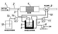
同図を参照すると、本発明の第1発明は、例えば船舶用ディーゼルエンジン等の内燃機関などの排ガス源1からの排気通路2に、上流側から順に還元剤供給用管(還元剤供給手段)3と脱硝触媒層4が配置され、前記還元剤供給用管3より還元剤が前記触媒層4に添加され、排ガス中の窒素酸化物が還元されて、排ガスが浄化される排ガス浄化システムであって、液体還元剤を貯留させるための液体還元剤貯留槽5と、コンプレッサー(圧縮空気供給手段)6とを備えており、前記液体還元剤貯留槽5内で気化した還元剤に対して前記コンプレッサー6から圧縮空気が供給(パージ)されて、気化還元剤同伴空気が形成され、この気化還元剤同伴空気が前記還元剤供給管3に供給されることを特徴としている。
Referring to FIG. 1, a first invention of the present invention is a reducing agent supply pipe (reducing agent supply means) in order from an upstream side to an
この実施形態においては、液体還元剤貯留槽5上部の空間内に、コンプレッサー6から導管7を経て圧縮空気を供給(パージ)することで、気化還元剤同伴空気を形成し、この気化還元剤同伴空気を前記還元剤供給管3より排気通路2内に供給する。
In this embodiment, by supplying (purging) compressed air from the
ここで、液体還元剤として用いることができる化合物としては、メタノール、エタノール、プロパノール等のアルコール類、ジエチルエーテル等のエーテル類、メチルエチルケトン等のケトン類、および軽油、灯油、ガソリン等の炭化水素よりなる群の中から選ばれた少なくとも1つの低分子量の有機化合物であることが好ましい。 Here, the compounds that can be used as the liquid reducing agent include alcohols such as methanol, ethanol, and propanol, ethers such as diethyl ether, ketones such as methyl ethyl ketone, and hydrocarbons such as light oil, kerosene, and gasoline. It is preferably at least one low molecular weight organic compound selected from the group.
また、例えば船舶用ディーゼルエンジン等の内燃機関の排ガスなどの浄化処理にあたり、上記液体還元剤を用いた脱硝触媒システムにおける脱硝触媒としては、有効成分がゼオライトである脱硝触媒を使用するのが好ましい。 Further, for example, in the purification treatment of exhaust gas from an internal combustion engine such as a marine diesel engine, it is preferable to use a denitration catalyst whose active ingredient is zeolite as the denitration catalyst in the denitration catalyst system using the liquid reducing agent.
そして、本発明の第1発明において、気化還元剤同伴空気中の気化還元剤濃度を一定にするために、液体還元剤貯留槽5の温度を一定に保つことが好ましい。
In the first invention of the present invention, it is preferable to keep the temperature of the liquid reducing
この実施形態においては、液体還元剤貯留槽5の周壁にジャケット式加熱器(加熱手段)8が設けられ、この加熱器8によって貯留槽5内の液体還元剤の温度が調整される。そしてこの場合、脱硝触媒層4の下流側の排気通路2に循環熱媒体加熱用熱交換器9が設置され、該熱交換器9と上記加熱器8とは熱媒体循環管10によって接続されており、熱媒体循環管10の途上に介在させられたポンプ11の作動によって、貯留槽5のジャケット式加熱器8から加熱用循環熱媒体が熱交換器9に送り込まれ、この熱交換器9おいて循環熱媒体が、触媒層4から排出された浄化排ガスの排熱で加温された後、液体還元剤貯留槽5のジャケット式加熱器8に返送されて、貯留槽5の温度が一定に保持されることが好ましい。
In this embodiment, a jacket type heater (heating means) 8 is provided on the peripheral wall of the liquid reducing
ここで、液体還元剤として、例えばエタノール(沸点78.37℃)を使用した場合、液体還元剤貯留槽5の液体還元剤の温度を、40℃以上、60℃以下に保持することが好ましい。このとき、例えば脱硝触媒層4の下流側の排気通路2に設置された熱交換器9において、触媒層4から排出された浄化排ガスの排熱で循環熱媒体を、例えば50℃に加温した後、熱媒体循環管10によって貯留槽5のジャケット式加熱器8に返送し、貯留槽5の温度を50℃に保持することが好ましい。
Here, when, for example, ethanol (boiling point 78.37 ° C.) is used as the liquid reducing agent, the temperature of the liquid reducing agent in the liquid reducing
上記のように、脱硝触媒層4の下流側の排気通路2に循環熱媒体加熱用熱交換器9が設置されて、脱硝触媒層4から排出された浄化排ガスの排熱を利用して、液体還元剤貯留槽5の温度が一定に保持されている。ここで、循環熱媒体としては、通常、水を使用するが、その他、ペンタン、イソペンタン、ブタン、プロパン等の低分子炭化水素、およびフロン(R134a、R245fa)等を用いることができる。循環熱媒体は、回収する排熱の温度分布に応じて最適なものが選定される。
As described above, the circulating heat medium heating heat exchanger 9 is installed in the
本発明の第1発明の排ガス浄化システムにおいて、コンプレッサー6から導管7を経て液体還元剤貯留槽5の上部空間内に供給する圧縮空気の流量および貯留槽内液体還元剤温度を制御することにより、排ガスに添加する気化還元剤量を制御することが好ましい。
In the exhaust gas purification system of the first invention of the present invention, by controlling the flow rate of compressed air supplied from the
上記のように、貯留槽5内の液体還元剤の温度を所定温度(例えば50℃)に保持することにより、貯留槽5の上部空間内の気化還元剤の蒸気圧は一定に保持され、貯留槽5の上部空間内の気化還元剤の濃度が一定となる。従って、貯留槽5の上部空間内に供給する圧縮空気の流量および貯留槽内液体還元剤温度を制御することにより、圧縮空気に同伴される気化還元剤の量も制御され、この気化還元剤同伴空気を還元剤供給管3から排気通路2内の排ガスに添加することにより、排ガスへの気化還元剤の添加量を制御することが可能となる。
As described above, by keeping the temperature of the liquid reducing agent in the
また、気化還元剤同伴空気中の気化還元剤濃度を一定にするために、液体還元剤貯留槽5内の液体還元剤の貯留量を一定に保つことが好ましい。
Further, in order to make the concentration of the vapor reducing agent in the vapor reducing agent accompanying air constant, it is preferable to keep the amount of the liquid reducing agent stored in the liquid reducing
すなわち、本発明の第1発明の排ガス浄化システムにおいて、さらに液体還元剤保管槽12を備えており、前記液体還元剤貯留槽5には液面計(レベルスイッチ)(図示略)が設置され、この液面計からの貯留槽5内の液体還元剤の上面(液面)のレベル検知信号に基づいて、還元剤液面レベルが貯留下限値を下回った際に、液体還元剤保管槽12からポンプ14の作動により導管13を経て液体還元剤を補充し、還元剤液面レベルが貯留上限値を上回った際に、ポンプ14の作動を止めて、液体還元剤の補充を停止することにより、液体還元剤貯留槽5に供給される還元剤の供給量を制御することが好ましい。
That is, the exhaust gas purification system of the first invention of the present invention further includes a liquid reducing
本発明の第1発明によれば、例えば船舶用ディーゼルエンジン等の内燃機関の排ガスのように、排ガス温度が200〜400℃程度の比較的低温域の排ガスであっても、アルコール、炭化水素などの液体還元剤を用いて、しかも排ガスに添加する際に、事前に気化した還元剤を供給することができるため、液体還元剤の気化熱による排ガス温度の低下を抑制し、高い脱硝性能を維持することができる。そのうえ、液体還元剤貯留槽5の上部空間内に供給する圧縮空気の流量および貯留槽内液体還元剤温度を制御することにより、圧縮空気に同伴される気化還元剤の量を制御することができ、この気化還元剤同伴空気を還元剤供給管3から排気通路2内の排ガスに添加することにより、排ガスへの気化還元剤の添加量の制御が容易であり、実用性に優れているものである。
According to the first invention of the present invention, alcohol, hydrocarbons, etc., even if the exhaust gas temperature is a relatively low temperature exhaust gas having a temperature of about 200 to 400 ° C., such as exhaust gas from an internal combustion engine such as a marine diesel engine. In addition, it is possible to supply a pre-vaporized reducing agent when it is added to the exhaust gas, thus suppressing a decrease in exhaust gas temperature due to the heat of vaporization of the liquid reducing agent and maintaining high denitration performance. can do. In addition, by controlling the flow rate of the compressed air supplied into the upper space of the liquid reducing
図2は、本発明の第1発明による排ガス浄化システムの第2実施形態を示すフローシートである。 FIG. 2 is a flow sheet showing a second embodiment of the exhaust gas purification system according to the first invention of the present invention.
ここで、上記第1発明の第1実施形態の場合と異なる点は、液体還元剤貯留槽5に内部加熱器(加熱手段)15が設けられ、この内部加熱器15によって貯留槽5内の液体還元剤の温度が調整される点にある。そしてこの場合、脱硝触媒層4の下流側の排気通路2に循環熱媒体加熱用熱交換器9が設置され、該熱交換器9と上記内部加熱器15とは熱媒体循環管10によって接続されており、熱媒体循環管10の途上に介在させられたポンプ11の作動によって、貯留槽5の内部加熱器15から加熱用循環熱媒体が熱交換器9に送り込まれ、この熱交換器9おいて循環熱媒体が、触媒層4から排出された浄化排ガスの排熱で加温された後、液体還元剤貯留槽5の内部加熱器15に返送されて、貯留槽5の温度が一定に保持されることが好ましい。このとき、例えば液体還元剤としてエタノールを使用した場合、例えば脱硝触媒層4の下流側の排気通路2に設置された熱交換器9において、触媒層4から排出された浄化排ガスの排熱で循環熱媒体を、例えば50℃に加温した後、熱媒体循環管10によって貯留槽5の内部加熱器15に返送し、貯留槽5の温度を50℃に保持することが好ましい。
Here, the difference from the case of the first embodiment of the first invention is that an internal heater (heating means) 15 is provided in the liquid reducing
なお、第1発明の第2実施形態の排ガス浄化システムにおいて、コンプレッサー6から導管7を経て液体還元剤貯留槽5の上部空間内に供給する圧縮空気の流量および貯留槽内液体還元剤温度を制御することにより、排ガスに添加する気化還元剤量を制御したり、気化還元剤同伴空気中の気化還元剤濃度を一定にするために、液体還元剤貯留槽5に液面計(レベルスイッチ)(図示略)を設置して、貯留槽5中の液体還元剤の貯留レベルを一定に保持するなど点は、上記第1発明の第1実施形態の場合と同様である。
In the exhaust gas purification system according to the second embodiment of the first invention, the flow rate of compressed air supplied from the
この第1発明の第2実施形態において、その他の点は、上記第1発明の第1実施形態の場合と同様であるので、図2において、上記図1と同一のものには、同一の符号を付した。 In the second embodiment of the first invention, the other points are the same as in the case of the first embodiment of the first invention. Therefore, in FIG. 2, the same components as those in FIG. Was attached.
図3は、本発明の第2発明による排ガス浄化システムの第1実施形態を示すフローシートである。 FIG. 3 is a flow sheet showing the first embodiment of the exhaust gas purification system according to the second invention of the present invention.
同図を参照すると、本発明の第2の発明は、例えば船舶用ディーゼルエンジン等の内燃機関などの排ガス源1からの排気通路2に、上流側から順に還元剤供給用管(還元剤供給手段)3と脱硝触媒層4が配置され、前記還元剤供給用管3より還元剤が前記触媒層4に添加され、排ガス中の窒素酸化物が還元されて、排ガスが浄化される排ガス浄化システムであって、液体還元剤を貯留させるための液体還元剤貯留槽5と、還元剤気化用熱交換器16とを備えており、液体還元剤貯留槽5からポンプ18の作動により導管17を経て導出された還元剤が熱交換器16において加熱されて気化せしめられ、この気化還元剤が、前記還元剤供給管3に供給されることを特徴としている。
Referring to the figure, a second invention of the present invention is a reducing agent supply pipe (reducing agent supply means) in order from the upstream side to an
この第2発明の排ガス浄化システムにおいて、還元剤気化用熱交換器16が、脱硝触媒層4の下流側の排気通路2に設置され、該熱交換器16において触媒層4から排出された浄化排ガスの排熱で液体還元剤が加熱されて気化せしめられることが好ましい。
In the exhaust gas purification system of the second invention, the reducing agent
本発明の第2本発明の排ガス浄化システムにおいて、液体還元剤として用いることができる化合物は、上記第1発明の場合と同様に、アルコール類、エーテル類、ケトン類、および炭化水素よりなる群の中から選ばれた少なくとも1つの低分子量の有機化合物である。 In the exhaust gas purification system of the second invention of the present invention, the compound that can be used as the liquid reducing agent is the group consisting of alcohols, ethers, ketones, and hydrocarbons, as in the first invention. It is at least one organic compound having a low molecular weight selected from among them.
ここで、液体還元剤として、例えばエタノール(沸点78.37℃)を使用した場合、脱硝触媒層4の下流側の排気通路2に設置された熱交換器16において触媒層4から排出された浄化排ガスの排熱でエタノールよりなる還元剤が沸点以上に加熱されて気化せしめられ、この気化還元剤が、還元剤供給管3より排気通路2内に供給されるものである。
Here, when, for example, ethanol (boiling point 78.37 ° C.) is used as the liquid reducing agent, the purification exhausted from the catalyst layer 4 in the
本発明の第2発明の排ガス浄化システムにおいては、液体還元剤貯留槽5からポンプ18の作動により導出される液体還元剤の導出量を制御することにより、排ガスに添加する気化還元剤量を制御することが好ましい。
In the exhaust gas purification system of the second invention of the present invention, the amount of vaporized reducing agent added to the exhaust gas is controlled by controlling the amount of liquid reducing agent derived from the liquid reducing
本発明の第2発明の排ガス浄化システムにおいて、さらに液体還元剤保管槽12を備えており、液体還元剤保管槽12からポンプ14の作動により導管13を経て液体還元剤を液体還元剤貯留槽5に補充するようになされている。ここで、液体還元剤貯留槽5内の液体還元剤の貯留量を保持するには、例えば液体還元剤貯留槽5からポンプ18の作動により導管17を経て気化用熱交換器16に導出される還元剤の導出量に対応して、液体還元剤保管槽12からポンプ14の作動により同量の液体還元剤を液体還元剤貯留槽5に補充するように、両ポンプ14,18の導出量を制御することが好ましい。
In the exhaust gas purification system of the second invention of the present invention, a liquid reducing
本発明の第2発明の排ガス浄化システムによれば、例えば船舶用ディーゼルエンジン等の内燃機関の排ガスのように、排ガス温度が200〜400℃程度の比較的低温域の排ガスであっても、アルコール、炭化水素などの液体還元剤を用いて、しかも排ガスに添加する際に、事前に気化した還元剤を供給することができるため、液体還元剤の気化熱による排ガス温度の低下を抑制し、高い脱硝性能を維持することができる。そのうえ、液体還元剤貯留槽5からポンプ18の作動により導出される液体還元剤の導出量を制御することにより、排ガスへの気化還元剤の添加量の制御が容易であり、実用性に優れているものである。
According to the exhaust gas purification system of the second aspect of the present invention, even if the exhaust gas temperature is an exhaust gas in a relatively low temperature range of about 200 to 400 ° C., such as exhaust gas of an internal combustion engine such as a marine diesel engine, alcohol In addition, when a liquid reducing agent such as hydrocarbon is used and added to the exhaust gas, a reducing agent vaporized in advance can be supplied, so that a reduction in the exhaust gas temperature due to the heat of vaporization of the liquid reducing agent is suppressed and high. Denitration performance can be maintained. In addition, by controlling the amount of the liquid reducing agent derived from the liquid reducing
つぎに、本発明の実施例を比較例と共に説明するが、本発明は、これらの実施例に限定されるものではない。 Next, examples of the present invention will be described together with comparative examples, but the present invention is not limited to these examples.
(実施例1)
本発明の第1発明の第1実施形態のフローシートを示す図1に基づいて本発明の排ガス浄化システムを実施した。
Example 1
The exhaust gas purification system of the present invention was implemented based on FIG. 1 showing the flow sheet of the first embodiment of the first invention of the present invention.
同図を参照すると、本発明の排ガス浄化システムにおいて、例えば船舶用ディーゼルエンジン等の内燃機関などの排ガス源1からの排気通路2に、上流側から順に還元剤供給用管(還元剤供給手段)3と脱硝触媒層4が配置され、さらに排ガス浄化システムには、液体還元剤を貯留させるための液体還元剤貯留槽5と、コンプレッサー(圧縮空気供給手段)6とを備えている。
Referring to the figure, in the exhaust gas purification system of the present invention, for example, a reducing agent supply pipe (reducing agent supply means) is sequentially supplied from an upstream side to an
ここで、排ガスとしては、酸素(O2)を13.8〔vol%−dry〕、水(H2O)を5.0〔vol%−wet〕、窒素酸化物(NOx)を1000〔ppmvd〕、硫黄酸化物(SOx)を600〔ppmvd〕、それぞれ含有する合成ガスを使用し、250〔℃〕の温度で排気通路2に供給した。
Here, as the exhaust gas, oxygen (O 2) 13.8 [vol% -dry], water (H 2 O) 5.0 [vol% -wet], nitrogen oxides (NOx) 1000 [ppmvd The synthesis gas containing 600 [ppmvd] of sulfur oxide (SOx) was used and supplied to the
脱硝触媒層4には、コバルトをイオン交換したゼオライトが担持されたコルゲート・ハニカム構造型脱硝触媒を充填した。 The denitration catalyst layer 4 was filled with a corrugated honeycomb structure type denitration catalyst on which zeolite ion-exchanged cobalt was supported.
また、液体還元剤としてエタノール(CH3CH2OH:沸点78.37℃、5000〔ppmvd〕)を使用した。そして、脱硝触媒層4の下流側の排気通路2に設置された循環水加熱用熱交換器9において、触媒層4から排出された浄化排ガスの排熱で循環水を、例えば50℃に加温した後、温水循環管10によって液体エタノール貯留槽5のジャケット式加熱器8に返送し、貯留槽5の温度を50℃に保持した。
Further, ethanol (CH 3 CH 2 OH: boiling point 78.37 ° C., 5000 [ppmvd]) was used as a liquid reducing agent. Then, in the circulating water heating heat exchanger 9 installed in the
そして、液体エタノール貯留槽5上部の空間内に、コンプレッサー6から導管7を経て圧縮空気を供給(パージ)することで、気化エタノール同伴空気を形成し、この気化エタノール同伴空気を前記還元剤供給管3より排気通路2内に供給し、排ガスおよび還元剤としての気化エタノールを触媒層4の脱硝触媒に接触させて、脱硝反応による排ガスの浄化を実施した。このとき、脱硝触媒層4における面積速度を5.0(m/h)とし、反応温度を250℃とした。
Then, by supplying (purging) compressed air from the
ここで、面積速度は、ハニカム型脱硝触媒のガス接触面積あたりの処理ガス量であり、次式で表される。 Here, the area velocity is a processing gas amount per gas contact area of the honeycomb type denitration catalyst, and is represented by the following equation.
面積速度=処理ガス量(Nm3/h)/ガス接触面積(m2)
なお、貯留槽5内の液体エタノールの温度を50℃に保持することにより、貯留槽5の上部空間内の気化還元剤の蒸気圧は一定に保持され、貯留槽5の上部空間内の気化還元剤の濃度が一定となった。このため、貯留槽5の上部空間内に供給する圧縮空気の流量および貯留槽内液体還元剤温度を制御することにより、圧縮空気に同伴される気化還元剤の量も制御され、この気化還元剤同伴空気を還元剤供給管3から排気通路2内の排ガスに添加することにより、排ガスへの気化還元剤の添加量を制御することができた。
Area velocity = treatment gas amount (Nm 3 / h) / gas contact area (m 2 )
In addition, by keeping the temperature of the liquid ethanol in the
また、気化エタノール同伴空気を前記還元剤供給管3より排気通路2内に供給する際の気化エタノール同伴空気の温度は、約50℃であるが、排ガスに添加する際に、事前に気化したエタノールよりなる還元剤を供給することができるため、液体エタノールの気化熱による排ガス温度の低下を抑制することができ、脱硝触媒層4の入口の排ガス温度は、約250℃と変わらず、これによって、触媒層4の触媒による高い脱硝性能を維持することができた。
Further, the temperature of the vaporized ethanol-entrained air when the vaporized ethanol-entrained air is supplied from the reducing
下記の表1に、排ガス源1から排気通路2に導入した排ガスの温度と、還元剤供給管3より気化エタノール同伴空気を排気通路2内に供給した後の脱硝触媒層入口の排ガス温度を示した。
Table 1 below shows the temperature of the exhaust gas introduced from the
なお、この実施例においては、図示は省略したが、気化エタノール同伴空気中の気化エタノール濃度を一定にするために、貯留槽5内の液体エタノールの貯留量を一定に保持するようにした。このため、排ガス浄化システムにさらに液体エタノール保管槽12を備え、前記液体エタノール貯留槽5には液面計(レベルスイッチ)を設置して、この液面計からの貯留槽5内の液体エタノールの上面(液面)のレベル検知信号に基づき、エタノール液面レベルが貯留下限値を下回った際に、液体エタノール保管槽12からポンプ14の作動により導管13を経て液体エタノールを補充し、エタノール液面レベルが貯留上限値を上回った際に、ポンプ14の作動を止めて、液体エタノールの補充を停止することにより、液体エタノール貯留槽5に供給されるエタノールの供給量を制御するようにした。
In this embodiment, although not shown, in order to keep the vaporized ethanol concentration in the vaporized ethanol accompanying air constant, the amount of liquid ethanol stored in the
(実施例2)
上記第1実施例の場合と同様にして、本発明の排ガス浄化システムを実施するが、第1実施例の場合と異なる点は、本発明の第1発明の第2実施形態のフローシートを示す図2に基づいて排ガス浄化システムを実施した点にある。すなわち、液体還元剤貯留槽5の内部に加熱器(加熱手段)15が設けられ、この内部加熱器15によって貯留槽5内の液体還元剤の温度を調整した。具体的には、液体還元剤としてエタノールを使用し、脱硝触媒層4の下流側の排気通路2に設置された熱交換器9において、触媒層4から排出された浄化排ガスの排熱で循環水を、50℃に加温した後、温水循環管10によって貯留槽5の内部加熱器15に返送し、貯留槽5の温度を50℃に保持した。
(Example 2)
The exhaust gas purification system of the present invention is implemented in the same manner as in the case of the first example, but the difference from the case of the first example is the flow sheet of the second embodiment of the first invention of the present invention. The exhaust gas purification system is implemented based on FIG. That is, a heater (heating means) 15 was provided inside the liquid reducing
この第2実施例において、その他の点は、上記第1実施例の場合と同様であり、下記の表1に、排ガス源1から排気通路2に導入した排ガスの温度と、還元剤供給管3より気化エタノール同伴空気を排気通路2内に供給した後の脱硝触媒層入口の排ガス温度をあわせて示した。
In the second embodiment, the other points are the same as in the case of the first embodiment. Table 1 below shows the temperature of the exhaust gas introduced from the
(実施例3)
上記第1実施例の場合と同様にして、本発明の排ガス浄化システムを実施するが、第1実施例の場合と異なる点は、本発明の第2発明の第1実施形態のフローシートを示す図3に基づいて排ガス浄化システムを実施した点にある。
(Example 3)
The exhaust gas purification system of the present invention is implemented in the same manner as in the case of the first example, but the difference from the case of the first example is the flow sheet of the first embodiment of the second invention of the present invention. The exhaust gas purification system is implemented based on FIG.
同図を参照すると、本発明の排ガス浄化システムにおいて、排ガス源1からの排気通路2に、上流側から順に還元剤供給用管(還元剤供給手段)3と脱硝触媒層4が配置され、さらに排ガス浄化システムには、液体還元剤を貯留させるための液体還元剤貯留槽5と、還元剤気化用熱交換器16とを備えており、液体還元剤貯留槽5からポンプ18の作動により導管17を経て導出された還元剤が熱交換器16において加熱されて気化せしめられ、この気化還元剤が、前記還元剤供給管3に供給される。この第3実施例において、還元剤気化用熱交換器16が、脱硝触媒層4の下流側の排気通路2に設置され、該熱交換器16において触媒層4から排出された浄化排ガスの排熱で液体還元剤が加熱されて気化せしめられる。上記実施例1の場合と同様に、液体還元剤としてエタノール(沸点78.37℃)を使用しており、脱硝触媒層4の下流側の排気通路2に設置された熱交換器16において触媒層4から排出された浄化排ガスの排熱でエタノールよりなる液体還元剤を120℃に加熱して気化させ、この気化還元剤を、還元剤供給管3より排気通路2内に供給した。
Referring to the figure, in the exhaust gas purification system of the present invention, a reducing agent supply pipe (reducing agent supply means) 3 and a denitration catalyst layer 4 are disposed in the
ここで、気化エタノールを還元剤供給管3より排気通路2内に供給する際の気化エタノールの温度は、約120℃であるが、排ガスに添加する際に、事前に気化したエタノールよりなる還元剤を供給することができるため、液体エタノールの気化熱による排ガス温度の低下を抑制することができ、脱硝触媒層4の入口の排ガス温度は、約250℃と変わらず、これによって、高い脱硝性能を維持することができた。
Here, the temperature of vaporized ethanol when the vaporized ethanol is supplied from the reducing
下記の表1に、排ガス源1から排気通路2に導入した排ガスの温度と、還元剤供給管3より気化エタノールを排気通路2内に供給した後の脱硝触媒層入口の排ガス温度をあわせて示した。
Table 1 below shows the temperature of the exhaust gas introduced from the
なお、液体エタノール貯留槽5からポンプ18の作動により導管17を経て気化用熱交換器16に導出される液体エタノールの導出量に対応して、液体エタノール保管槽12からポンプ14の作動により同量の液体エタノールを貯留槽5に補充するように、両ポンプ14,18の導出量を制御することにより、液体エタノール貯留槽5内の液体エタノールの貯留量を保持した。
Incidentally, the same amount is obtained from the liquid
(比較例1)
比較のために、従来の排ガス浄化システムのフローシートを示す図4に基づいて排ガス浄化システムを実施した。
(Comparative Example 1)
For comparison, an exhaust gas purification system was implemented based on FIG. 4 showing a flow sheet of a conventional exhaust gas purification system.
同図を参照すると、従来の排ガス浄化システムにおいて、排ガス源21からの排気通路22に、上流側から順に還元剤供給用管(還元剤供給手段)23と脱硝触媒層24が配置され、さらに排ガス浄化システムには、液体還元剤を貯留させるための液体還元剤貯留槽25を備えており、液体還元剤貯留槽25からポンプ26の作動により導出された還元剤を、供給管23から排気通路22内に直接導入して、排ガス中で気化させた。液体還元剤としては、上記実施例1の場合と同様に、エタノール(沸点78.37℃)を使用した。
Referring to the figure, in a conventional exhaust gas purification system, a reducing agent supply pipe (reducing agent supply means) 23 and a
その結果、液体エタノールの気化熱による排ガス温度の低下が生じて、脱硝触媒層24の入口の排ガス温度は、243℃に低下した。これによって、脱硝触媒層24の脱硝反応の温度が低下するため、触媒層24の脱硝性能は低下したものと考えられる。
As a result, the exhaust gas temperature decreased due to the heat of vaporization of liquid ethanol, and the exhaust gas temperature at the inlet of the
下記の表1に、排ガス源21から排気通路22に導入した排ガスの温度と、還元剤供給管23より液体エタノールを排気通路22内に直接供給した後の脱硝触媒層24入口の排ガス温度をあわせて示した。
Table 1 below shows the temperature of the exhaust gas introduced from the
なお、この比較例1の排ガス浄化システムにおいて、さらに液体還元剤保管槽27を備えており、液体還元剤保管槽27からポンプ29の作動により導管28を経て液体エタノールを液体エタノール貯留槽25に補充するようにした。

上記表1に記載の結果から明らかなように、本発明の実施例1〜3の排ガス浄化システムによれば、排ガス温度が250℃程度の比較的低温域の排ガスであっても、エタノールよりなる液体還元剤を用いて、しかも排ガスに添加する際に、事前に気化した還元剤を供給することができるため、液体還元剤の気化熱による排ガス温度の低下を抑制し、脱硝触媒層4入口の温度を低下させることなく、還元剤であるエタノールを添加することができ、脱硝触媒層4での高い脱硝性能を維持することができた。そのうえ、排ガスへの気化還元剤の添加量の制御が容易であり、実用性に優れていることが確認できた。 As is clear from the results shown in Table 1 above, according to the exhaust gas purification systems of Examples 1 to 3 of the present invention, even the exhaust gas at a relatively low temperature range of about 250 ° C. is made of ethanol. When the liquid reducing agent is used and added to the exhaust gas, the reducing agent vaporized in advance can be supplied. Therefore, the reduction of the exhaust gas temperature due to the heat of vaporization of the liquid reducing agent is suppressed, and the inlet of the denitration catalyst layer 4 is suppressed. Without reducing the temperature, ethanol as a reducing agent could be added, and high denitration performance in the denitration catalyst layer 4 could be maintained. In addition, it was easy to control the amount of vaporization reducing agent added to the exhaust gas, and it was confirmed that it was excellent in practicality.
これに対し、比較例1によれば、脱硝触媒層24の上流側の排気通路22に、エタノールよりなる還元剤を液体の状態で直接導入し、導入から脱硝触媒層24に到達するまでの間にエタノールよりなる還元剤を気化させているため、還元剤の気化熱により排ガスの温度低下が生じ、脱硝触媒層4における触媒の脱硝性能が低下するという問題が生じた。
On the other hand, according to Comparative Example 1, a reducing agent made of ethanol is directly introduced into the
1:内燃機関などの排ガス源
2:排気通路
3:還元剤供給用管(還元剤供給手段)
4:脱硝触媒層
5:液体還元剤貯留槽
6:コンプレッサー(圧縮空気供給手段)
7:導管
8:ジャケット式加熱器(加熱手段)
9:循環水加熱用熱交換器(循環熱媒体加熱用熱交換器)
10:温水循環管(熱媒体循環管)
11:ポンプ
12:液体還元剤保管槽
13:導管
14:ポンプ
15:内部加熱器(加熱手段)
16:還元剤気化用熱交換器
17:導管
18:ポンプ
1: exhaust gas source such as an internal combustion engine 2: exhaust passage 3: reducing agent supply pipe (reducing agent supply means)
4: Denitration catalyst layer 5: Liquid reducing agent storage tank 6: Compressor (compressed air supply means)
7: Conduit 8: Jacket type heater (heating means)
9: Heat exchanger for circulating water heating (heat exchanger for circulating heat medium heating)
10: Hot water circulation pipe (heat medium circulation pipe)
11: Pump 12: Liquid reducing agent storage tank 13: Conduit 14: Pump 15: Internal heater (heating means)
16: Heat exchanger for reducing agent vaporization 17: Conduit 18: Pump
Claims (6)
液体還元剤貯留槽と、圧縮空気供給手段とを備えており、前記液体還元剤貯留槽の液体還元剤の温度は沸点以下に保持され、前記液体還元剤貯留槽内で前記圧縮空気供給手段から圧縮空気が供給されて気化した還元剤に対して気化還元剤同伴空気が形成され、この気化還元剤同伴空気が前記還元剤供給手段に供給されることを特徴とする、排ガス浄化システム。 In the exhaust passage of the internal combustion engine, a reducing agent supply means and a denitration catalyst layer are arranged in order from the upstream side , and at least one selected from the group consisting of alcohol, ether, ketones, and hydrocarbons from the reducing agent supply means. In the exhaust gas purification system in which a reducing agent that is one organic compound is added to the exhaust gas upstream of the catalyst layer, nitrogen oxides in the exhaust gas are reduced, and the exhaust gas is purified.
A liquid reducing agent reservoir, and a compressed air supply means, the temperature of the liquid reducing agent in the liquid reducing agent reservoir is held below the boiling point, before in the liquid reducing agent storage tank Symbol compressed air supply means An exhaust gas purification system, wherein vaporized reducing agent-entrained air is formed with respect to the reducing agent that is vaporized by supplying compressed air from the air, and the vaporized reducing agent-entrained air is supplied to the reducing agent supply means.
Priority Applications (2)
| Application Number | Priority Date | Filing Date | Title |
|---|---|---|---|
| JP2013028082A JP6140470B2 (en) | 2013-02-15 | 2013-02-15 | Exhaust gas purification system |
| PCT/JP2014/053160 WO2014126090A1 (en) | 2013-02-15 | 2014-02-12 | Exhaust gas purification system |
Applications Claiming Priority (1)
| Application Number | Priority Date | Filing Date | Title |
|---|---|---|---|
| JP2013028082A JP6140470B2 (en) | 2013-02-15 | 2013-02-15 | Exhaust gas purification system |
Publications (3)
| Publication Number | Publication Date |
|---|---|
| JP2014156821A JP2014156821A (en) | 2014-08-28 |
| JP2014156821A5 JP2014156821A5 (en) | 2016-03-03 |
| JP6140470B2 true JP6140470B2 (en) | 2017-05-31 |
Family
ID=51354090
Family Applications (1)
| Application Number | Title | Priority Date | Filing Date |
|---|---|---|---|
| JP2013028082A Active JP6140470B2 (en) | 2013-02-15 | 2013-02-15 | Exhaust gas purification system |
Country Status (2)
| Country | Link |
|---|---|
| JP (1) | JP6140470B2 (en) |
| WO (1) | WO2014126090A1 (en) |
Families Citing this family (3)
| Publication number | Priority date | Publication date | Assignee | Title |
|---|---|---|---|---|
| GB201421869D0 (en) * | 2014-12-09 | 2015-01-21 | Delphi International Operations Luxembourg S.�.R.L. | SCR dosing system |
| CN112879126B (en) * | 2021-01-21 | 2022-05-13 | 天津大学 | Non-catalytic double-reducing agent NOx removal method and device |
| US11649761B1 (en) | 2021-12-22 | 2023-05-16 | Caterpillar Inc. | Systems for methanol vaporization |
Family Cites Families (5)
| Publication number | Priority date | Publication date | Assignee | Title |
|---|---|---|---|---|
| JPH05272331A (en) * | 1992-03-25 | 1993-10-19 | Hino Motors Ltd | Exhaust emission control device and reducing agent supply method and device used therein |
| JPH09267025A (en) * | 1996-03-29 | 1997-10-14 | Kawasaki Heavy Ind Ltd | Supplying method of reducing agent for denitrification of exhaust gas |
| JP4917208B2 (en) * | 2001-01-22 | 2012-04-18 | 川崎重工業株式会社 | Method and apparatus for supplying liquid reducing agent for denitration apparatus |
| JP4888480B2 (en) * | 2008-12-15 | 2012-02-29 | 株式会社デンソー | Control device for exhaust purification system |
| JP5804090B2 (en) * | 2012-02-03 | 2015-11-04 | トヨタ自動車株式会社 | Exhaust gas purification device for internal combustion engine |
-
2013
- 2013-02-15 JP JP2013028082A patent/JP6140470B2/en active Active
-
2014
- 2014-02-12 WO PCT/JP2014/053160 patent/WO2014126090A1/en active Application Filing
Also Published As
| Publication number | Publication date |
|---|---|
| JP2014156821A (en) | 2014-08-28 |
| WO2014126090A1 (en) | 2014-08-21 |
Similar Documents
| Publication | Publication Date | Title |
|---|---|---|
| EP1901831B1 (en) | Method and device for safe and controlled delivery of ammonia from a solid ammonia storage medium | |
| JP6140470B2 (en) | Exhaust gas purification system | |
| JP7417013B2 (en) | Exhaust gas treatment method for thermal power plants | |
| JP5487453B2 (en) | Exhaust treatment system | |
| JP6357234B2 (en) | In particular, an exhaust gas purification method for an internal combustion engine, especially an automobile, and an apparatus using the same | |
| JP2011122593A (en) | Method for treating pollutant contained in exhaust gas of internal combustion engine, and pollutant treatment system using the same | |
| KR20190091480A (en) | Preparation of Ammonium Carbamate and Reduction of Nitrogen Oxide | |
| JP5383648B2 (en) | Low temperature urea injection method | |
| JP6850413B2 (en) | Exhaust gas treatment equipment for thermal power plants | |
| JP4646063B2 (en) | Exhaust gas denitration method and apparatus using urea decomposition catalyst | |
| JP4661452B2 (en) | Exhaust gas purification system control method and exhaust gas purification system | |
| JP6175510B2 (en) | Method and apparatus for urea regulation and injection control in a selective catalytic reduction system | |
| JP5949318B2 (en) | Catalytic reaction apparatus and vehicle | |
| KR102413070B1 (en) | Cooling device for reducing agent dosing module and engine cooling system having the same | |
| CN101617104B (en) | Method and device for producing ammonia for exhaust gas treatment in internal combustion engines in motor vehicle | |
| JPWO2013124997A1 (en) | Power generation device, power generation method, cracked gas boiler, and cracked gas turbine | |
| US20130045139A1 (en) | Method To Enhance The Ash Storage Capacity Of A Particulate Filter | |
| JP2012157830A (en) | Exhaust gas treatment apparatus | |
| CN207822795U (en) | Composite type ship harbour oil gas minimum discharge retracting device | |
| JP2013130179A (en) | Internal combustion engine control device | |
| JP2008303786A (en) | Exhaust emission control device of internal combustion engine | |
| JP2011144055A (en) | Fuel reforming apparatus | |
| JPH08257365A (en) | Method and apparatus for denitrating exhaust gas | |
| JP2004251196A (en) | Apparatus for producing reformed gas, method for producing reformed gas employing this apparatus and exhaust emission control system | |
| TW201104062A (en) | De-NOx, intelligent, full-featured diesel engine exhaust treatment system |
Legal Events
| Date | Code | Title | Description |
|---|---|---|---|
| A521 | Request for written amendment filed |
Free format text: JAPANESE INTERMEDIATE CODE: A523 Effective date: 20160115 |
|
| A621 | Written request for application examination |
Free format text: JAPANESE INTERMEDIATE CODE: A621 Effective date: 20160115 |
|
| A131 | Notification of reasons for refusal |
Free format text: JAPANESE INTERMEDIATE CODE: A131 Effective date: 20161101 |
|
| A521 | Request for written amendment filed |
Free format text: JAPANESE INTERMEDIATE CODE: A523 Effective date: 20161228 |
|
| TRDD | Decision of grant or rejection written | ||
| A01 | Written decision to grant a patent or to grant a registration (utility model) |
Free format text: JAPANESE INTERMEDIATE CODE: A01 Effective date: 20170404 |
|
| A61 | First payment of annual fees (during grant procedure) |
Free format text: JAPANESE INTERMEDIATE CODE: A61 Effective date: 20170501 |
|
| R150 | Certificate of patent or registration of utility model |
Ref document number: 6140470 Country of ref document: JP Free format text: JAPANESE INTERMEDIATE CODE: R150 |
|
| R250 | Receipt of annual fees |
Free format text: JAPANESE INTERMEDIATE CODE: R250 |