JP6140459B2 - Sensor data transmission device - Google Patents
Sensor data transmission device Download PDFInfo
- Publication number
- JP6140459B2 JP6140459B2 JP2013011963A JP2013011963A JP6140459B2 JP 6140459 B2 JP6140459 B2 JP 6140459B2 JP 2013011963 A JP2013011963 A JP 2013011963A JP 2013011963 A JP2013011963 A JP 2013011963A JP 6140459 B2 JP6140459 B2 JP 6140459B2
- Authority
- JP
- Japan
- Prior art keywords
- interface
- sensor
- signal
- data
- slave
- Prior art date
- Legal status (The legal status is an assumption and is not a legal conclusion. Google has not performed a legal analysis and makes no representation as to the accuracy of the status listed.)
- Active
Links
Images


Classifications
-
- G—PHYSICS
- G06—COMPUTING; CALCULATING OR COUNTING
- G06F—ELECTRIC DIGITAL DATA PROCESSING
- G06F13/00—Interconnection of, or transfer of information or other signals between, memories, input/output devices or central processing units
- G06F13/14—Handling requests for interconnection or transfer
- G06F13/36—Handling requests for interconnection or transfer for access to common bus or bus system
-
- G—PHYSICS
- G05—CONTROLLING; REGULATING
- G05B—CONTROL OR REGULATING SYSTEMS IN GENERAL; FUNCTIONAL ELEMENTS OF SUCH SYSTEMS; MONITORING OR TESTING ARRANGEMENTS FOR SUCH SYSTEMS OR ELEMENTS
- G05B19/00—Programme-control systems
- G05B19/02—Programme-control systems electric
- G05B19/04—Programme control other than numerical control, i.e. in sequence controllers or logic controllers
- G05B19/05—Programmable logic controllers, e.g. simulating logic interconnections of signals according to ladder diagrams or function charts
- G05B19/056—Programming the PLC
-
- G—PHYSICS
- G06—COMPUTING; CALCULATING OR COUNTING
- G06F—ELECTRIC DIGITAL DATA PROCESSING
- G06F13/00—Interconnection of, or transfer of information or other signals between, memories, input/output devices or central processing units
- G06F13/38—Information transfer, e.g. on bus
- G06F13/42—Bus transfer protocol, e.g. handshake; Synchronisation
- G06F13/4282—Bus transfer protocol, e.g. handshake; Synchronisation on a serial bus, e.g. I2C bus, SPI bus
- G06F13/4291—Bus transfer protocol, e.g. handshake; Synchronisation on a serial bus, e.g. I2C bus, SPI bus using a clocked protocol
-
- H—ELECTRICITY
- H04—ELECTRIC COMMUNICATION TECHNIQUE
- H04L—TRANSMISSION OF DIGITAL INFORMATION, e.g. TELEGRAPHIC COMMUNICATION
- H04L12/00—Data switching networks
- H04L12/28—Data switching networks characterised by path configuration, e.g. LAN [Local Area Networks] or WAN [Wide Area Networks]
- H04L12/40—Bus networks
- H04L12/40006—Architecture of a communication node
-
- H—ELECTRICITY
- H04—ELECTRIC COMMUNICATION TECHNIQUE
- H04L—TRANSMISSION OF DIGITAL INFORMATION, e.g. TELEGRAPHIC COMMUNICATION
- H04L12/00—Data switching networks
- H04L12/28—Data switching networks characterised by path configuration, e.g. LAN [Local Area Networks] or WAN [Wide Area Networks]
- H04L12/46—Interconnection of networks
- H04L12/4604—LAN interconnection over a backbone network, e.g. Internet, Frame Relay
- H04L12/462—LAN interconnection over a bridge based backbone
- H04L12/4625—Single bridge functionality, e.g. connection of two networks over a single bridge
-
- H—ELECTRICITY
- H04—ELECTRIC COMMUNICATION TECHNIQUE
- H04Q—SELECTING
- H04Q9/00—Arrangements in telecontrol or telemetry systems for selectively calling a substation from a main station, in which substation desired apparatus is selected for applying a control signal thereto or for obtaining measured values therefrom
-
- G—PHYSICS
- G05—CONTROLLING; REGULATING
- G05B—CONTROL OR REGULATING SYSTEMS IN GENERAL; FUNCTIONAL ELEMENTS OF SUCH SYSTEMS; MONITORING OR TESTING ARRANGEMENTS FOR SUCH SYSTEMS OR ELEMENTS
- G05B2219/00—Program-control systems
- G05B2219/20—Pc systems
- G05B2219/25—Pc structure of the system
- G05B2219/25217—Configure communication protocol, select between several
-
- G—PHYSICS
- G05—CONTROLLING; REGULATING
- G05B—CONTROL OR REGULATING SYSTEMS IN GENERAL; FUNCTIONAL ELEMENTS OF SUCH SYSTEMS; MONITORING OR TESTING ARRANGEMENTS FOR SUCH SYSTEMS OR ELEMENTS
- G05B2219/00—Program-control systems
- G05B2219/30—Nc systems
- G05B2219/31—From computer integrated manufacturing till monitoring
- G05B2219/31121—Fielddevice, field controller, interface connected to fieldbus
-
- H—ELECTRICITY
- H04—ELECTRIC COMMUNICATION TECHNIQUE
- H04Q—SELECTING
- H04Q2209/00—Arrangements in telecontrol or telemetry systems
- H04Q2209/30—Arrangements in telecontrol or telemetry systems using a wired architecture
-
- H—ELECTRICITY
- H04—ELECTRIC COMMUNICATION TECHNIQUE
- H04Q—SELECTING
- H04Q2209/00—Arrangements in telecontrol or telemetry systems
- H04Q2209/80—Arrangements in the sub-station, i.e. sensing device
- H04Q2209/84—Measuring functions
- H04Q2209/845—Measuring functions where the measuring is synchronized between sensing devices
Description
本発明は、請求項1に記載のセンサーデータを伝送するための装置に関する。特に、本発明による装置を用いて、測定器と制御器の間のインタフェース接続部を介して、その制御器にセンサーの測定値を伝送することができる。
The invention relates to a device for transmitting sensor data according to
自動化技術では、デジタル測定値を提供する測定器が益々用いられている。そのことは、例えば、工作機械の制御のために使用される数値制御分野において、特に、直線又は回転運動を測定する位置測定器に言えることである。デジタル測定値を発生する位置測定器は、絶対位置測定器と呼ばれる。 In automation technology, more and more instruments that provide digital measurements are used. This is particularly true in the field of numerical control used for machine tool control, particularly for position measuring instruments that measure linear or rotational movement. Position measuring devices that generate digital measurements are called absolute position measuring devices.
絶対位置の値を伝送するためには、数本のデータ伝送線しか必要とせず、それにも関わらず、データ伝送速度が高いので、主にシリアルデータインタフェースが用いられている。その場合、一本の片方向又は両方向のデータ線と一本のクロック線を備えた所謂同期シリアルインタフェースが特に有利である。データ線を介したデータパケットの伝送は、クロック線上のクロック信号と同期して行われる。自動化技術では、多数のデジタル標準インタフェースが広く普及しており、同期シリアルインタフェースの広く知られた代表的なものは、例えば、本出願人のEnDatインタフェースであり、別のものは、「SSI」との名称で知られている。それ以外に、例えば、Hiperfaceなどの非同期シリアルインタフェースも普及している。 In order to transmit the absolute position value, only a few data transmission lines are required. Nevertheless, since the data transmission speed is high, a serial data interface is mainly used. In that case, a so-called synchronous serial interface with one data line in one or both directions and one clock line is particularly advantageous. Transmission of the data packet via the data line is performed in synchronization with the clock signal on the clock line. In the automation technology, a large number of digital standard interfaces are widely used. A well-known representative example of the synchronous serial interface is, for example, Applicant's EnDat interface, and another is “SSI”. It is known by the name. In addition, asynchronous serial interfaces such as Hiperface are also widespread.
SSIインタフェースは、特許文献1に記載されている。それは、片方向のデータ線と片方向のクロック線を用いた同期シリアルデータインタフェースである。そこでは、位置測定器からの位置の値の読み出しは、クロック線上のクロック信号と同期して行われている。
The SSI interface is described in
それに対して、特許文献2は、本出願人のEnDatインタフェースの基本構成を記載している。それは、同じく同期シリアルインタフェースであるが、片方向のクロック線の外に、両方向のデータ線を有する。それによって、数値制御部から位置測定器へと、位置測定器から数値制御部への両方向でのデータ伝送が可能となっている。そこでも、データ伝送は、クロック線上のクロック信号と同期して行われている。 On the other hand, Patent Document 2 describes a basic configuration of Applicant's EnDat interface. It is also a synchronous serial interface, but has a bidirectional data line in addition to a unidirectional clock line. Thereby, data transmission in both directions is possible from the numerical control unit to the position measuring device and from the position measuring device to the numerical control unit. Even in this case, data transmission is performed in synchronization with the clock signal on the clock line.
更に、多くの場合、例えば、位置測定器と数値制御部の間の既存のインタフェース接続部を介して、測定器内で検出又は計算したデータの外に、外部機器又はセンサーが発生したデータも伝送したいとの要求が有る。 Furthermore, in many cases, data generated by an external device or sensor is transmitted in addition to data detected or calculated in the measuring instrument, for example, via an existing interface connection between the position measuring instrument and the numerical control unit. There is a request to do.
即ち、特許文献3は、外部のセンサーに接続できる追加インタフェースをロータリーエンコーダに配備し、エンコーダ内でセンサーデータを処理して、バスインタフェースを介して制御部に伝送できるようにすることを提案している。 That is, Patent Document 3 proposes that an additional interface that can be connected to an external sensor is arranged in the rotary encoder, the sensor data is processed in the encoder, and can be transmitted to the control unit via the bus interface. Yes.
特許文献4は、一方では周辺機器、例えば、センサーに接続でき、他方では通信インタフェースを用いて位置測定装置と接続できる中間のコンポーネントを記載している。その位置測定装置は、又もやインタフェース接続部を介してセンサーデータの処理及び/又は数値制御部の方向にセンサーデータを出力することが可能である。
これら二つの変化形態は、ロータリーエンコーダにおいて、更に取り付けた状態でもアクセスできなければならない少なくとも一つの追加インタフェースを必要とする。 These two variations require at least one additional interface in the rotary encoder that must be accessible even when installed.
本発明の課題は、測定器を改修すること無く、測定器と制御器の間のインタフェース接続部を介して、その制御器にセンサー信号を伝送できる手段を実現することである。 An object of the present invention is to realize a means capable of transmitting a sensor signal to a controller via an interface connection between the measuring instrument and the controller without modifying the measuring instrument.
本課題は、請求項1に記載の装置によって解決される。本装置の有利な詳細は、請求項1に従属する請求項から明らかとなる。
This problem is solved by the device according to
そこで、
・制御器のマスターインタフェースに接続可能なスレーブインタフェースと、
・測定器のスレーブインタフェースに接続可能なマスターインタフェースと、
・センサーと接続可能な少なくとも一つのセンサーインタフェースと、
・改変ユニットとプロトコルユニットを有する回路機器と、
を備えており、
・この改変ユニットは、マスターインタフェースのマスターデータ入力信号とセンサーデータ出力信号を供給されて、スレーブデータ出力信号をスレーブインタフェースに出力し、
・このプロトコルユニットは、スレーブインタフェース又はマスターインタフェースのプロトコルに関連する少なくとも一つのインタフェース信号とセンサーインタフェースのセンサーデータ信号を供給されて、このプロトコルユニットは、センサーデータ信号からセンサーデータ出力信号を生成するとともに、改変規則とプロトコルに関連する少なくとも一つのインタフェース信号に基づき、何時改変ユニットがスレーブデータ出力信号としてマスターインタフェースのマスターデータ入力信号又はセンサーデータ出力信号を出力するのかを選択することが可能である、
インタフェース信号を改変するための装置を提案する。
there,
A slave interface that can be connected to the master interface of the controller;
A master interface that can be connected to the slave interface of the measuring instrument,
At least one sensor interface connectable to the sensor;
A circuit device having a modification unit and a protocol unit;
With
This modification unit is supplied with the master interface master data input signal and sensor data output signal, and outputs the slave data output signal to the slave interface.
The protocol unit is provided with at least one interface signal related to the slave interface or master interface protocol and the sensor data signal of the sensor interface, and the protocol unit generates a sensor data output signal from the sensor data signal. Based on at least one interface signal related to the modification rule and the protocol, it is possible to select when the modification unit outputs the master data input signal or the sensor data output signal of the master interface as the slave data output signal.
A device for modifying the interface signal is proposed.
本発明の更に別の利点と詳細は、以下における図面に基づく記載から明らかとなる。 Further advantages and details of the present invention will become apparent from the following description based on the drawings.
図1は、制御器20と測定器30の間に配置されたインタフェース信号を改変するための装置10を図示している。制御器20は、少なくとも一つのシリアルインタフェースを備え、そのインタフェースに接続された測定器との通信に適した、自動化技術又は駆動技術の任意の機器とすることができる。その例は、位置表示器、数値制御部(NC)及びメモリプログラミング可能な制御部(SPS)である。以下の実施例では、制御器20の代わりに数値制御部20を使用している。測定器は、特に、例えば、軸Wの回転角及び/又は回転した回数を測定するための位置測定器30である。
FIG. 1 illustrates an
本装置10は、数値制御部20とのデータ交換のために、第一のインタフェースケーブル13を用いて、数値制御部20のインタフェースコントローラ24のマスターインタフェース22と接続されるスレーブインタフェース12を備えている。更に、本装置は、第二のインタフェースケーブル19を用いて、位置測定器30のスレーブインタフェース32と接続されるマスターインタフェース18を備えている。本装置10の中央ユニットは、インタフェース信号を処理する回路機器15である。この回路機器15の構成は、以下において、図2と関連して詳しく説明する。
The
これらのインタフェースケーブルとインタフェースは、通常通り、好適なコネクタ接続部を備えており、そのため、本発明による装置は、自動化設備又は工作機械の設置が完了している場合でも、例えば、数値制御部20のマスターインタフェース22と位置測定器30のスレーブインタフェース32の間の接続を切り離して、数値制御部20のマスターインタフェース22と本装置10のスレーブインタフェース12の間及び位置測定器30のスレーブインタフェース32と本装置10のマスターインタフェース18の間の接続をそれぞれ行うことによって、数値制御部20と位置測定器30の間に簡単に差し込むことができる。完璧を期すために、通常は、インタフェースケーブルを介して、位置測定器30への電源供給も行っており、それに対応して本装置10の接続部を構成すること(図示されていない)にも言及しておく。そのような電源供給も、本装置10の動作形態に関して考慮することができる。
These interface cables and interfaces are provided with suitable connector connections as usual, so that the device according to the invention can be used, for example, even when the installation of automation equipment or machine tools is complete, for example the
例えば、数値制御部20、本装置10及び位置測定器30において、地電位と関連した簡単なデジタル信号として生成、処理されたインタフェース信号を長距離に渡って妨害されない形での伝送に適した信号に変換するために、これらのインタフェースは、周知の通り、ドライバ及びレシーバモジュールを更に備えることができる。周知のRS−485に基づくデジタル信号の差動伝送を可能とするドライバ及びレシーバモジュールが特に普及している。同様に、デジタルインタフェース信号を光ファイバーを介して伝送する光学信号に変換することも知られており、有利である。
For example, in the
数値制御部20において、アプリケーションインタフェース27,28を介してインタフェースコントローラ24と接続された制御ユニット26は、位置測定器30が如何なるデータを必要としているのか、或いは位置測定器30に送信するのかを決定する。その場合、インタフェースコントローラ24は、ほぼ一般的なアプリケーションインタフェース27,28の通信コマンドを数値制御部20の特別なマスターインタフェース22のインタフェース信号に変換する伝達ユニットとしての役割を果たす。位置測定器30において、必要なデータの準備又は受信データの処理は測定ユニット34で行われる。
In the
この制御ユニット26は、特に、マイクロコントローラ又はマイクロプロセッサに基づくプログラム制御ユニットである。制御ユニット26の機能の例は、測定器、例えば、位置測定器30から実際の値を要求されて、その値から駆動部を制御するための目標値を算出することによって、位置の値の読出しと表示、並びに複雑な制御サイクルを制御することである。
This
本発明では、少なくとも一つのセンサーインタフェース300が本装置10に配備されている。このセンサーインタフェース300は、アナログセンサー310と接続するためのアナログインタフェースとして、或いはデジタルセンサー310と接続するためのデジタルインタフェースとして実現することができる。
In the present invention, at least one
このセンサーインタフェース300がアナログインタフェースである場合、アナログセンサー信号、即ち、センサー310の測定値をデジタルセンサーデータ信号S_Mに変換するセンサーデータ処理ユニット320が本装置10に配備される。そのため、センサーデータ処理ユニット320には、好適な手段、例えば、A/D変換器が配備される。
When the
それに対して、センサーインタフェース300がデジタルインタフェースである場合、センサー310の測定値を含むデジタルセンサーデータ信号S_Mが、接続されたセンサー310から直接得られる。そのようなセンサーインタフェース300は、確かに基本的にスレーブインタフェース12又はマスターインタフェース18と同じ形式とすることができるが、それらの複雑さとデータ伝送速度は、多くの場合センサーデータの伝送に必要なものよりも大きいので、センサーインタフェース300としては、より簡単なシリアルインタフェースを用いることもできる。センサーインタフェース300を実現するための幾つかの例は、I2C、SPI又はJTAGインタフェースである。更に、例えば、IrDA標準により光学式又はブルートゥース又はZigBee標準による無線リンク式のワイヤレスインタフェースも使用可能である。同様に、センサーインタフェース300をRFID読取機として構成し、センサーをRFIDタグとして構成することもできる。
On the other hand, when the
デジタルセンサーデータ信号S_Mは、回路機器15に供給される。その場合、その時々のセンサー値は、センサーデータ信号S_Mを介して、自発的に連続して、或いは短い時間間隔で回路機器15に伝送するか、さもなければ回路機器15の要求に応じてのみ伝送することができる。後者の場合、回路機器15は、センサーインタフェース300の制御部の役割を果たす。
The digital sensor data signal S_M is supplied to the
更に、本装置10には、別のインタフェースケーブル45を用いて改変ユニット40を接続できる保守インタフェース16を配備することができる。この保守インタフェース16は、プログラミングと回路機器15の機能制御の両方の役割を果たす。この保守インタフェース16も、所定のインタフェース変化形態に固定されず、基本的にセンサーインタフェース300用としても選定できるものと同じ実施形態が検討の対象となる。
Furthermore, the
実際には、商用のパーソナルコンピュータ、特に、ラップトップ又はノートブックを保守ユニット40として採用するのが特に有利である。そのような機器は、同じく保守インタフェース16としても適したUSB又はイーサネットインタフェースを標準装備している。別個の保守ユニット40の代わりに、制御器20の(図示されていない)追加インタフェースを介して本装置10を保守する手法も有る。
In practice, it is particularly advantageous to employ a commercial personal computer, in particular a laptop or notebook, as the
(図示されていない)任意選択として、本装置10において、例えば、キーパッドとして保守部品を実現して、一行又は複数行のディスプレイの形の表示ユニットを配置し、それらを介して、回路機器15のプログラミング及び/又は保守を行うこともできる。そのようにして、複雑な保守機能、例えば、センサーインタフェース300に接続されたセンサー310、データフォーマット、インタフェースプロトコルなどの選択を本装置10で直接行うことができ、そのため、本装置を自立的な機器として動かすことができる。
As an option (not shown), in the
この例では、数値制御部20のマスターインタフェース22は、EnDatインタフェースである。そのため、物理的なデータ伝送は、冒頭で述べた特許文献2に記載されている通り、二対の線によるRS−485標準に基づく差動信号の形で行われ、第一の対の線は、両方向にデータを伝送する役割を果たし、第二の対の線は、片方向にクロック信号を伝送する役割を果たす。データの伝送は、クロック信号と同期して行われる。このようなインタフェースでは、クロック信号TCLK、データ入力信号DIN及びデータ出力信号DOUTの三つのインタフェース信号を内部で処理しなければならない。データの方向、即ち、データ出力信号を能動的に出力するのか否かの設定は、データ伝送プロトコルに対応して切り換えられるイネーブル信号OENによって行われる。
In this example, the master interface 22 of the
以下において、本装置10のスレーブインタフェース12を数値制御部20のマスターインタフェース22と通信させる役割を果たすスレーブインタフェース信号は、スレーブデータ入力信号DIN_S、スレーブデータ出力信号DOUT_S、スレーブクロック信号TCLK_S及びスレーブイネーブル信号OEN_Sと称する。それと同様に、本装置10のマスターインタフェース18と位置測定器30のスレーブインタフェース32の通信は、マスターインタフェース信号、特に、マスターデータ入力信号DIN_M、マスターデータ出力信号DOUT_M、マスタークロック信号TCLK_M及びマスターイネーブル信号OEN_Mによって行われる。対応するインタフェース信号は、それぞれスレーブデータ入力信号DIN_Sとマスターデータ出力信号DOUT_M、スレーブクロック信号TCLK_Sとマスタークロック信号TCLK_M、並びにマスターデータ入力信号DIN_Mとスレーブデータ出力信号DOUT_Sである。
In the following, the slave interface signals that play a role in causing the
図2は、回路機器15のブロック接続図を図示している。中央のプロトコルユニット100は、プロトコルと関連するインタフェース信号、即ち、データ伝送プロトコルの検知及び処理に適した信号を供給される。この例では、(数値制御部20から位置測定器30に送信されるコマンドを識別するための)スレーブデータ入力信号DIN_Sと、(データ伝送を同期させるための)スレーブクロック信号TCLK_Sとがプロトコルと関連するインタフェース信号である。同様に、例えば、プロトコルの流れが位置測定器30の応答データ又は所定の応答データの着信時点に依存する場合、データ入力信号DIN_Mもプロトコルと関連する信号とすることができる。そのようなプロトコルの流れから生じる、その時々のデータの方向に応じて、プロトコルユニット100は、スレーブイネーブル信号OEN_Sとマスターイネーブル信号OEN_Mも生成する。更に、プロトコルユニット100は、マスターインタフェース18を介して、位置測定器30にマスタークロック信号TCLK_Mも出力する。
FIG. 2 is a block connection diagram of the
更に、プロトコルユニット100は、センサーデータ信号S_Mを供給される。如何なる任意のデジタルデータ伝送方法もセンサーデータ信号S_Mをプロトコルユニット100に伝送するのに適しており、有利には、センサーデータ信号S_Mは、シリアルデジタルデータフローの形でプロトコルユニット100に伝送される。既に前に述べた通り、その時々のセンサー値が、センサーデータ信号S_Mによって、要求されない形で連続して、或いは短い時間間隔で着信するか、或いはその時々のセンサー値の伝送がプロトコルユニット100によって開始される。
Furthermore, the
回路機器15は、プロトコルユニット100の外に、改変ユニット110を備えている。その第一の入力には、マスターデータ入力信号DIN_Mが供給され、第二の入力には、プロトコルユニット100においてセンサーデータ信号S_Mから生成されたセンサーデータ出力信号SOUTと、場合によっては、補正データ信号Xが供給される。改変ユニット110は、その出力に、スレーブデータ出力信号DOUT_Sを数値制御部20の方向に出力する。改変ユニット110内の変換器112は、マスターデータ入力信号DIN_M、センサー出力データ信号SOUT又は補正データ信号Xの何れをスレーブデータ出力信号SOUTとして出力するのかを決定する。言い換えると、この変換器112によって、マスターデータ入力信号DIN_Mにより位置測定器30から着信したデータの代わりに、代替データ、特に、センサーデータ出力信号SOUTを数値制御部20に出力する手段が実現される。
The
この変換器112の制御は、プロトコルユニット100によって行われる。それは、有利には、プロトコルと関連するインタフェース信号により数値制御部20から着信する情報、特に、コマンドを検知し、その情報に応じて、所定の改変規則に基づき変換器112の制御を行う状態制御オートマトンとして実現される。
The control of the
更に、プロトコルユニット100は、センサーデータ信号S_Mからセンサーデータ出力信号SOUTを生成し、そのため、その信号は、スレーブ出力データ信号DOUT_Sとして出力されるデータフロー内に隙間無く挿入される。ここで述べた例では、データがマスターデータ入力信号DIN_Mとして位置測定器30からマスタークロック信号TCLK_Mと同期して改変ユニット110に着信して、スレーブ出力データ信号DOUT_Sとして数値制御部20の方向に再送され、それは、プロトコルユニット100が同じくマスタークロック信号TCLK_Mと同期した出力のために改変ユニット110に出力されるデータシーケンスをセンサーデータ出力信号SOUTとして生成することを意味する。更に、センサーデータ出力信号SOUTの生成のために実施されるオペレーションは、データフォーマットの変換又はセンサーデータ信号S_M内に含まれるセンサー値の分解能への適合を含むことができる。
Furthermore, the
センサーデータ出力信号SOUTの出力は、数値制御部20においてエラーとして解釈されるスレーブ出力データ信号DOUT_Sの矛盾を引き起こす。そのような矛盾を取り除くために、プロトコルユニット100において、更に、センサーデータ出力信号SOUTと同様に、改変ユニット110に供給して、マスターデータ入力信号DIN_Mの代わりにスレーブ出力データ信号DOUT_Sとして数値制御部20に出力することができる補正データ信号Xを生成することができる。プロトコルユニット100は、又もやプロトコルに関連するインタフェース信号、即ち、例えば、スレーブデータ入力信号DIN_S、スレーブクロック信号TCLK_S又はマスターデータ入力信号DIN_Mに基づき、データ伝送の如何なる位置で補正データ信号Xを出力するのかを決定する。
The output of the sensor data output signal SOUT causes a contradiction in the slave output data signal DOUT_S that is interpreted as an error in the
それに関する例:データ伝送を保証するために、或いはデータが数値制御部20に正しく着信したか否かの制御手段として、多くの場合、送信器(位置測定器30)がチェックサムCRC(周期的冗長検査)を生成して、同じく数値制御部20に伝送する。ここで、データフローが改変されて、伝送されてきたデータの一部がセンサーデータ出力信号SOUTによって置き換えられていた場合、チェックサムCRCが最早伝送されてきたデータと合致せず、数値制御部20が、そのような矛盾においてエラーを検知する。この場合、それを防止するために、プロトコルユニット100が、マスターデータ入力信号DIN_Mに含まれるデータとセンサー出力データワードSOUTから、変更されたデータを考慮した新たなチェックサムを生成して、それを補正データ信号Xとして位置測定器30から送られてきたチェックサムの代わりに出力する。センサーデータ出力信号SOUTの出力と同様に、補正データ信号Xの出力は、マスタークロック信号TCLK_Mと同期して行われる。
Examples relating thereto: In many cases, a transmitter (position measuring device 30) is used as a checksum CRC (periodic) to guarantee data transmission or as a control means of whether data has arrived correctly at the
プロトコルユニット100は、回路機器15でも生成されず、その機器に外部からも供給されない動作クロック信号CLKと同期して動作する。数値制御部20の方向から回路機器15に着信するインタフェース信号が、この例では具体的にはスレーブクロック信号TCLK_Sとスレーブデータ入力信号DIN_Sが、動作クロック信号CLKと同期していない場合、それらの信号を早くも回路機器15の入力において同期ユニット102,104を用いて動作クロック信号CLKと同期させるのが有利である。しかし、この場合、これらの信号は、時間的に遅れるだけであり、それ以外は大幅に変更されていない。それによって、位置測定器30の応答データも遅れて数値制御部20に着信するので、そのような遅延は、長いインタフェースケーブル13,19を用いた場合と同様に数値制御部20に作用する。インタフェース信号を処理できるためには、動作クロック信号CLKの周波数は、スレーブクロック信号TCLK_Sの最大限期待できる周波数以上でなければならない。基本的に、動作クロック信号CLKの周波数が高くなる程、インタフェース信号の時間的な遅延が小さくなる。実際に、スレーブクロック信号TCLK_Sの最大周波数が10MHzの場合、動作クロック信号CLKの周波数範囲を40〜100MHzとするのが有利であることが分かった。
The
改変規則は、例えば、プロトコルユニット100内に固定的に保存することができる。しかし、改変メモリ130を設けて、その内容を保守インタフェース16を介して保守ユニット40と通信する通信ユニット140によってプログラミング可能とするのが特に有利である。位置測定器30から着信した本来のデータの代わりにセンサー出力信号SOUTを伝送するために、数値制御部20が位置測定器30に送信するコマンドの中のどれを使用するのかを改変メモリ130内に保存することができる。そのようにして、本装置10は、変更された要件に柔軟に適合することができる。
The modification rule can be fixedly stored in the
有利には、プログラミング可能なモジュール、例えば、FPGA(フィールドプログラマブルゲートアレイ)が回路機器15として用いられる。そのようなモジュールは、何時でも新たにプログラムすることができ、従って、本発明による装置10の改変手段の変更及び/又は拡張に対応するのに最適である。同様に、マイクロコントローラも、簡単にプログラムを変更できて、変更された条件に適合させることができるので、回路機器15として好適である。回路機器15のプログラミングは、例えば、同じく保守インタフェース16を介して行うことができる。
Advantageously, a programmable module, for example an FPGA (Field Programmable Gate Array) is used as the
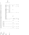
図3は、本発明による装置10の動作形態を図解するための簡略化したデータ伝送シーケンスを図示している。特に、回路機器15においてインタフェース信号の処理又は同期によって生じる僅かな時間的遅延を図示することは省略している。数値制御部20から位置測定器30への特別な位置要求コマンドの伝送を図示しており、それに対して、位置測定器30がその時々の位置データPOSと追加データZを数値制御部20に送信している。追加データとは、例えば、位置測定器30内のメモリからのデータとすることができる。一方では、伝送の安全性を向上するために、位置要求コマンドは冗長的に設計されている、特に、例えば、それぞれ3ビットから成る第一のコマンドブロックC1と第二のコマンドブロックC2から構成されており、第二のコマンドブロックC2は、第一のコマンドブロックC1と単に同じか、或いは反転して繰り返されたものである。他方では、位置測定器30は、それに続いてチェックサムCRCを送信する。
FIG. 3 illustrates a simplified data transmission sequence for illustrating the mode of operation of the
本装置10では、前述した位置要求コマンドに関する改変規則として、追加データZの代わりに、センサー310としてセンサーインタフェース300に接続された温度センサーの温度値を数値制御部20に伝送することが保存されている。そのため、この改変規則は、如何なる時点で改変ユニット110を切り換えて、スレーブデータ出力信号DOUT_Sとして、マスターデータ入力信号DIN_Mの代わりに、センサー出力信号SOUTとそれに応じて変更されたチェックサムCRCを出力しなければならないのかを決定する。
In the
ここで、改変規則を必ずしもデータ伝送プロトコルの枠組みにおいて数値制御部20から位置測定器30に送られるコマンドに対応付ける必要がないことを明確に指摘しておきたい。むしろ、数値制御部20又は位置測定器30から本装置10又は回路機器100に着信する如何なる任意の情報も改変規則に対応付けることができる。最も簡単な場合、クロック信号の始まり、即ち、データ伝送の開始でも改変規則に対応付ける情報と看做すことができる。
Here, it should be clearly pointed out that the modification rule does not necessarily have to be associated with a command sent from the
図3に図示されたデータ伝送シーケンスの第一列は、数値制御部20から回路機器15に着信するスレーブクロック信号TCLK_S又は(遅延を無視して)回路機器15から位置測定器30に転送されるマスタークロック信号TCLK_Mを図示している。
The first column of the data transmission sequence illustrated in FIG. 3 is transferred from the
第二列は、コマンドブロックC1及びC2を含む、場合によっては、同期ユニット102における動作クロック信号CLKとの同期後に、位置測定器30の方向にマスターデータ出力信号DOUT_Mとして転送されるスレーブデータ入力信号DIN_Sを図示している。
The second column includes command blocks C1 and C2, and possibly slave data input signals transferred as master data output signal DOUT_M in the direction of
第三列には、位置測定器30の応答データを含むマスターデータ入力信号DIN_Mが図示されている。
In the third column, a master data input signal DIN_M including response data of the
最後に、第四列は、プロトコルユニット100によって生成されるセンサーデータ出力信号SOUTと補正データ信号Xを図示しており、前者はセンサーデータ信号S_Mから生成され、後者は数値制御部20に送られてきたデータフロー全体から生成される。
Finally, the fourth column shows the sensor data output signal SOUT and the correction data signal X generated by the
時間的なフローは、次の通りである。 The temporal flow is as follows.
スレーブクロック信号TCLK_Sがアクティブとなった後、先ずはデータ方向の転換が行われる。アイドル状態では、スレーブイネーブル信号OEN_Sがアクティブに切り換えられており、マスターイネーブル信号OEN_Mがパッシブに切り換えられているとの仮定の下で、プロトコルユニット100は、時点t1とt2の間の転換時間間隔U1において、先ずはスレーブイネーブル信号OEN_Sをパッシブに切り換えてから、マスターイネーブル信号OEN_Mをアクティブに切り換える。この転換は、データの衝突を防止するために時間的に段階的に行われる。
After the slave clock signal TCLK_S becomes active, first, the data direction is changed. In the idle state, under the assumption that the slave enable signal OEN_S has been switched active and the master enable signal OEN_M has been switched passively, the
時点t2以降、第一のコマンドブロックC1の伝送が行われて、時点t3以降、第二のコマンドブロックC2の伝送がそれに続く。 After time t2, transmission of the first command block C1 is performed, and after time t3, transmission of the second command block C2 follows.
第二のコマンドブロックC2の伝送が時点t4で終了し、そこで、プロトコルユニット100は、コマンドブロックC1,C2の比較によって、コマンドの伝送に誤りが無かったか否かを決定することができる。
Transmission of the second command block C2 ends at time t4, whereupon the
遅くとも時点t4では、プロトコルユニット100は、インタフェース信号の改変を行うべきか、即ち、この例での通り、そのコマンドに関して改変規則が存在するか否かを決定できるのに十分な情報を有する。そのような改変規則は、例えば、プロトコルユニット100で定義されているか、或いは改変メモリ130内に保存されている。
At the latest, at time t4, the
コマンドの伝送に続いて、データの方向を転換して、特に、プロトコルユニットがマスターイネーブル信号OEN_Mをパッシブに切り換えるとともに、スレーブイネーブル信号OEN_Sをアクティブに切り換えるための第二の転換時間間隔U2が時点t4以降、時点t5まで続く。 Subsequent to the transmission of the command, the direction of the data is changed, and in particular, the protocol unit switches the master enable signal OEN_M passively and the second conversion time interval U2 for switching the slave enable signal OEN_S to active is a time t4. Thereafter, it continues until time t5.
時点t5以降、位置測定器30から数値制御部20への応答データのデータの伝送が始まり、例えば、スタートビットと、それに続く位置測定器30の動作状態の推定を可能とする様々なステータスビットとから成るスタートシーケンスSTARTが最初に送信される。
After time t5, transmission of response data from the
スタートシーケンスSTARTに続いて、時点t6以降、位置の値POSが伝送される。 Subsequent to the start sequence START, the position value POS is transmitted after time t6.
生成されたコマンドに関する改変規則に応じて、プロトコルユニット100は、時点t7で改変ユニット110内のスイッチ素子112を切り換え、その結果、その時点以降、プロトコルユニット100がセンサーデータ信号S_Mから生成したセンサーデータ出力信号SOUTが、マスターデータ入力信号DIN_Mの代わりに、スレーブデータ出力信号DOUT_Sとして数値制御部20に出力される。
In accordance with the modification rule relating to the generated command, the
時点t8以降、直ちにチェックサムCRCの伝送が続き、スイッチ素子112は切り換えられた位置に留まり、プロトコルユニット100は、変更されたデータに適合したチェックサムCRCを補正データ語Xとして出力する。
After the time t8, the checksum CRC is immediately transmitted, the
時点t9で、データ伝送が終了し、プロトコルユニット100と改変ユニット110は、初期状態に戻る。
At time t9, the data transmission is completed, and the
図3と関連して述べた、数値制御部20のマスターインタフェース22と位置測定器30のスレーブインタフェースの間のデータ通信の改変に関する例が示す通り、本発明による装置10又は回路機器15は、センサー310の測定データを既存のインタフェース通信に取り込むための簡単で効果的な手段を提供する。そのために数値制御部20も位置測定器30も変更する必要がないことが特に有利である。
As described in connection with FIG. 3, the example according to the modification of data communication between the master interface 22 of the
Claims (7)
測定器(30)のスレーブインタフェース(32)に接続可能なマスターインタフェース(18)と、
センサー(310)に接続可能な少なくとも一つのセンサーインタフェース(300)と、
改変ユニット(110)とプロトコルユニット(100)を有する回路機器(15)と、
を備えた、センサーデータを伝送するための装置において、
改変ユニット(110)は、マスターインタフェース(18)のマスターデータ入力信号(DIN_M)とセンサーデータ出力信号(SOUT)を供給されて、スレーブデータ出力信号(DOUT_S)をスレーブインタフェース(12)に出力し、
プロトコルユニット(100)は、スレーブインタフェース(12)又はマスターインタフェース(18)のプロトコルに関連する少なくとも一つのインタフェース信号(DIN_S、TCLK_S、DIN_M)とセンサーインタフェース(300)のセンサーデータ信号(S_M)を供給されて、プロトコルユニット(100)は、センサーデータ信号(S_M)からセンサーデータ出力信号(SOUT)を生成することが可能であるとともに、改変規則と前記のプロトコルに関連する少なくとも一つのインタフェース信号(DIN_S、TCLK_S、DIN_M)とに基づき、何時改変ユニット(110)がマスターインタフェース(18)のマスターデータ入力信号(DIN_M)又はセンサーデータ出力信号(SOUT)をスレーブデータ出力信号(DOUT_S)として出力するのかを選択することが可能である、
装置。 A slave interface (12) connectable to a master interface (22) of the controller (20);
A master interface (18) connectable to a slave interface (32) of the measuring instrument (30);
At least one sensor interface (300) connectable to the sensor (310);
A circuit device (15) having a modification unit (110) and a protocol unit (100);
A device for transmitting sensor data comprising:
The modification unit (110) is supplied with the master data input signal (DIN_M) and the sensor data output signal (SOUT) of the master interface (18), and outputs the slave data output signal (DOUT_S) to the slave interface (12).
The protocol unit (100) supplies at least one interface signal (DIN_S, TCLK_S, DIN_M) related to the protocol of the slave interface (12) or the master interface (18) and the sensor data signal (S_M) of the sensor interface (300). The protocol unit 100 can generate a sensor data output signal SOUT from the sensor data signal S_M, and at least one interface signal DIN_S associated with the modified rule and the protocol. , TCLK_S, DIN_M), the modification unit (110) detects the master data input signal (DIN_M) or sensor data output signal (SOUT) of the master interface (18). It is possible to select whether to output as Budeta output signal (DOUT_S),
apparatus.
Applications Claiming Priority (2)
| Application Number | Priority Date | Filing Date | Title |
|---|---|---|---|
| DE102012201170A DE102012201170A1 (en) | 2012-01-27 | 2012-01-27 | Device for transmitting sensor data |
| DE102012201170.6 | 2012-01-27 |
Publications (2)
| Publication Number | Publication Date |
|---|---|
| JP2013156987A JP2013156987A (en) | 2013-08-15 |
| JP6140459B2 true JP6140459B2 (en) | 2017-05-31 |
Family
ID=47594257
Family Applications (1)
| Application Number | Title | Priority Date | Filing Date |
|---|---|---|---|
| JP2013011963A Active JP6140459B2 (en) | 2012-01-27 | 2013-01-25 | Sensor data transmission device |
Country Status (6)
| Country | Link |
|---|---|
| US (1) | US9304958B2 (en) |
| EP (1) | EP2621193B1 (en) |
| JP (1) | JP6140459B2 (en) |
| CN (1) | CN103295384B (en) |
| DE (1) | DE102012201170A1 (en) |
| ES (1) | ES2743246T3 (en) |
Families Citing this family (15)
| Publication number | Priority date | Publication date | Assignee | Title |
|---|---|---|---|---|
| CN103481120A (en) * | 2013-08-23 | 2014-01-01 | 上海师范大学 | Intelligent detection system for Duty parameters of machine tool |
| DE102014101754B4 (en) * | 2014-02-12 | 2015-11-19 | Infineon Technologies Ag | A SENSOR COMPONENT AND METHOD FOR SENDING A DATA SIGNAL |
| DE102014114316A1 (en) * | 2014-10-01 | 2016-04-07 | Knorr-Bremse Systeme für Nutzfahrzeuge GmbH | Device for transmitting and receiving a sensor signal |
| CN107172717B (en) * | 2016-03-08 | 2020-01-24 | 普天信息技术有限公司 | Bluetooth device and mutual searching method of Bluetooth device |
| FI127322B (en) | 2016-04-22 | 2018-03-29 | Maricare Oy | SENSOR AND SYSTEM FOR CONTROL |
| US20180098136A1 (en) * | 2016-09-30 | 2018-04-05 | Intel Corporation | Push telemetry data accumulation |
| DE102016222275A1 (en) * | 2016-11-14 | 2018-05-17 | Dr. Johannes Heidenhain Gmbh | Position measuring device and method for operating a position measuring device |
| CH714256A1 (en) * | 2017-10-18 | 2019-04-30 | Elesta Gmbh Ostfildern De Zweigniederlassung Bad Ragaz | Method for the serial transmission of data from a sensor to a security control device. |
| US10678297B2 (en) * | 2018-05-10 | 2020-06-09 | Ciena Corporation | Circuit communication systems with digital state devices |
| JP6826077B2 (en) * | 2018-08-08 | 2021-02-03 | ファナック株式会社 | Encoder and data transmission method |
| US11128936B2 (en) * | 2019-04-04 | 2021-09-21 | Mark D. Matlin | Thermal transmitting indicator |
| US11102030B2 (en) | 2019-06-27 | 2021-08-24 | Rockwell Automation Technologies, Inc. | Daisy chaining point-to-point link sensors |
| CN112327676A (en) * | 2020-09-17 | 2021-02-05 | 北京无线电测量研究所 | ENDAT data acquisition device, equipment and method |
| EP4080168A1 (en) * | 2021-04-20 | 2022-10-26 | Melexis Technologies NV | Sensor interfaces for functional safety applications |
| CN114268309B (en) * | 2022-02-28 | 2022-06-03 | 季华实验室 | Absolute value encoder interface circuit and control method |
Family Cites Families (22)
| Publication number | Priority date | Publication date | Assignee | Title |
|---|---|---|---|---|
| JPS57211693A (en) * | 1981-06-24 | 1982-12-25 | Hitachi Ltd | Data collection system |
| EP0171579B1 (en) | 1984-07-13 | 1988-03-09 | Max Stegmann Gmbh Uhren- und Elektroapparatefabrik | Arrangement for the serial transmission of measured values of at least one transducer |
| DE4342377B4 (en) | 1993-12-13 | 2010-08-12 | Dr. Johannes Heidenhain Gmbh | Arrangement and method for serial data transmission of a position measuring device |
| JP3294737B2 (en) | 1994-10-13 | 2002-06-24 | ドクトル・ヨハネス・ハイデンハイン・ゲゼルシヤフト・ミツト・ベシユレンクテル・ハフツング | Position measuring device |
| US6170470B1 (en) * | 1999-07-09 | 2001-01-09 | Brunswick Corporation | Fuel supply system for an internal combustion engine |
| DE10047924B4 (en) * | 2000-09-27 | 2004-08-05 | Siemens Ag | Drive control and method for networking a control unit with one or more encoder systems |
| US6920627B2 (en) * | 2002-12-13 | 2005-07-19 | Xilinx, Inc. | Reconfiguration of a programmable logic device using internal control |
| DE10306231A1 (en) | 2003-02-14 | 2004-08-26 | Dr. Johannes Heidenhain Gmbh | Electronic intermediate components for recording data for a peripheral unit transmit recorded data to a position-measuring device |
| US7380705B2 (en) * | 2003-08-28 | 2008-06-03 | Symbol Technologies, Inc. | Multi-interface data acquisition system and method thereof |
| JP2006048632A (en) * | 2004-03-15 | 2006-02-16 | Omron Corp | Sensor controller |
| JP2006020038A (en) * | 2004-07-01 | 2006-01-19 | Denso Corp | Physical quantity sensor device and inspecting device therefor |
| JP2008545319A (en) * | 2005-06-30 | 2008-12-11 | エヌエックスピー ビー ヴィ | Software layer for communication between RS-232 / I2C conversion IC and host |
| DE102006041056C5 (en) | 2006-09-01 | 2015-02-19 | Siemens Aktiengesellschaft | Encoder for connecting additional sensors and electrical machine with such a rotary encoder |
| CN100591880C (en) * | 2006-12-31 | 2010-02-24 | 三一重工股份有限公司 | Intelligent cantilever crane control device |
| DE102008053105A1 (en) * | 2008-10-24 | 2010-04-29 | Dr. Johannes Heidenhain Gmbh | Device and method for data transmission between a position measuring device and a subsequent electronics |
| DE102008054887B4 (en) * | 2008-12-18 | 2021-03-25 | Dr. Johannes Heidenhain Gmbh | Device and method for the automated recognition of an interface |
| JP5216603B2 (en) * | 2009-01-19 | 2013-06-19 | 株式会社キーエンス | Continuous sensor system, network unit, and sensor unit |
| PL216638B1 (en) * | 2009-03-31 | 2014-04-30 | Akademia Górniczo Hutnicza Im Stanisława Staszica | Interface for communication of measuring sensors with I2C busbar |
| US8175839B2 (en) * | 2009-06-26 | 2012-05-08 | Kulite Semiconductor Products, Inc. | Wireless interface for a plurality of transducers |
| DE102010026435B4 (en) * | 2010-07-08 | 2023-01-26 | Vitesco Technologies Germany Gmbh | Device for classifying an electrical contact between two connection elements |
| CN102170326B (en) * | 2011-03-23 | 2013-03-13 | 武汉华中数控股份有限公司 | Serial communication method of position measuring equipment and device thereof |
| KR101265647B1 (en) * | 2011-03-25 | 2013-05-22 | 엘지전자 주식회사 | A method of controlling a lighting part in a lighting system |
-
2012
- 2012-01-27 DE DE102012201170A patent/DE102012201170A1/en not_active Withdrawn
- 2012-10-26 ES ES12190110T patent/ES2743246T3/en active Active
- 2012-10-26 EP EP12190110.2A patent/EP2621193B1/en active Active
-
2013
- 2013-01-24 US US13/749,385 patent/US9304958B2/en active Active
- 2013-01-25 JP JP2013011963A patent/JP6140459B2/en active Active
- 2013-01-25 CN CN201310027900.0A patent/CN103295384B/en active Active
Also Published As
| Publication number | Publication date |
|---|---|
| US9304958B2 (en) | 2016-04-05 |
| EP2621193A3 (en) | 2017-11-15 |
| CN103295384B (en) | 2017-07-11 |
| JP2013156987A (en) | 2013-08-15 |
| US20130198428A1 (en) | 2013-08-01 |
| CN103295384A (en) | 2013-09-11 |
| ES2743246T3 (en) | 2020-02-18 |
| EP2621193A2 (en) | 2013-07-31 |
| EP2621193B1 (en) | 2019-08-14 |
| DE102012201170A1 (en) | 2013-08-01 |
Similar Documents
| Publication | Publication Date | Title |
|---|---|---|
| JP6140459B2 (en) | Sensor data transmission device | |
| US6430634B1 (en) | Bus controller and bus control system | |
| US9273984B2 (en) | Device and method for transmitting data between a position-measuring device and sequential electronics | |
| JP2016192172A (en) | Information processing device, information processing program, and information processing method | |
| CN101013316A (en) | Bus-type numerical control system and control method thereof | |
| JP5876240B2 (en) | Device and control device for manipulating interface signals | |
| JP5279920B2 (en) | Apparatus and method for automatically detecting an interface | |
| EP1434382B1 (en) | Serial data transferring apparatus | |
| JP6518496B2 (en) | Apparatus and method for generating trigger signal in position measuring instrument and position measuring instrument | |
| US10484198B2 (en) | Function connection unit comprising a parameter memory | |
| CN110178000B (en) | Communication adapter for a transmitter of a field device | |
| US11005681B2 (en) | Data transmission method between a primary master and primary slave via a bus line and between sub-slaves via the same bus line | |
| US11489525B1 (en) | Device and method for synchronous serial data transmission | |
| EP2784448B1 (en) | Synchronous serial interface circuit and motion control function module | |
| JP6941234B2 (en) | Logic analyzer | |
| US11080061B2 (en) | Pre-loading of instructions | |
| JP6201331B2 (en) | Synchronous serial interface circuit | |
| US7031876B2 (en) | Procedure and device for data transmission between a processing unit and several position measuring instruments | |
| KR930007081B1 (en) | Interface board of field-bus | |
| JP2010119254A (en) | Servo motor control apparatus | |
| JP2008176794A (en) | Method and device for parameterization of measuring device |
Legal Events
| Date | Code | Title | Description |
|---|---|---|---|
| A621 | Written request for application examination |
Free format text: JAPANESE INTERMEDIATE CODE: A621 Effective date: 20150904 |
|
| A977 | Report on retrieval |
Free format text: JAPANESE INTERMEDIATE CODE: A971007 Effective date: 20160727 |
|
| A131 | Notification of reasons for refusal |
Free format text: JAPANESE INTERMEDIATE CODE: A131 Effective date: 20160810 |
|
| A521 | Request for written amendment filed |
Free format text: JAPANESE INTERMEDIATE CODE: A523 Effective date: 20161031 |
|
| TRDD | Decision of grant or rejection written | ||
| A01 | Written decision to grant a patent or to grant a registration (utility model) |
Free format text: JAPANESE INTERMEDIATE CODE: A01 Effective date: 20170405 |
|
| A61 | First payment of annual fees (during grant procedure) |
Free format text: JAPANESE INTERMEDIATE CODE: A61 Effective date: 20170501 |
|
| R150 | Certificate of patent or registration of utility model |
Ref document number: 6140459 Country of ref document: JP Free format text: JAPANESE INTERMEDIATE CODE: R150 |
|
| R250 | Receipt of annual fees |
Free format text: JAPANESE INTERMEDIATE CODE: R250 |
|
| R250 | Receipt of annual fees |
Free format text: JAPANESE INTERMEDIATE CODE: R250 |
|
| R250 | Receipt of annual fees |
Free format text: JAPANESE INTERMEDIATE CODE: R250 |
|
| R250 | Receipt of annual fees |
Free format text: JAPANESE INTERMEDIATE CODE: R250 |