JP6140276B2 - Radial shaft seal and assembly including the same - Google Patents
Radial shaft seal and assembly including the same Download PDFInfo
- Publication number
- JP6140276B2 JP6140276B2 JP2015516100A JP2015516100A JP6140276B2 JP 6140276 B2 JP6140276 B2 JP 6140276B2 JP 2015516100 A JP2015516100 A JP 2015516100A JP 2015516100 A JP2015516100 A JP 2015516100A JP 6140276 B2 JP6140276 B2 JP 6140276B2
- Authority
- JP
- Japan
- Prior art keywords
- lip
- sealing
- shaft seal
- shaft
- annular
- Prior art date
- Legal status (The legal status is an assumption and is not a legal conclusion. Google has not performed a legal analysis and makes no representation as to the accuracy of the status listed.)
- Expired - Fee Related
Links
- 238000007789 sealing Methods 0.000 claims description 89
- 239000000428 dust Substances 0.000 claims description 42
- 238000009423 ventilation Methods 0.000 claims description 8
- 239000003921 oil Substances 0.000 description 40
- 238000009434 installation Methods 0.000 description 11
- 239000003566 sealing material Substances 0.000 description 8
- 239000000356 contaminant Substances 0.000 description 7
- 239000002184 metal Substances 0.000 description 7
- 229920001971 elastomer Polymers 0.000 description 3
- 239000000806 elastomer Substances 0.000 description 3
- 238000000034 method Methods 0.000 description 3
- 230000008901 benefit Effects 0.000 description 2
- 230000015572 biosynthetic process Effects 0.000 description 2
- 239000012530 fluid Substances 0.000 description 2
- 241000120283 Allotinus major Species 0.000 description 1
- 238000005452 bending Methods 0.000 description 1
- 230000000694 effects Effects 0.000 description 1
- 230000007717 exclusion Effects 0.000 description 1
- 239000010687 lubricating oil Substances 0.000 description 1
- 239000000463 material Substances 0.000 description 1
- 238000012986 modification Methods 0.000 description 1
- 230000004048 modification Effects 0.000 description 1
- 230000002093 peripheral effect Effects 0.000 description 1
- 230000003014 reinforcing effect Effects 0.000 description 1
- 239000007787 solid Substances 0.000 description 1
Images


Classifications
-
- F—MECHANICAL ENGINEERING; LIGHTING; HEATING; WEAPONS; BLASTING
- F16—ENGINEERING ELEMENTS AND UNITS; GENERAL MEASURES FOR PRODUCING AND MAINTAINING EFFECTIVE FUNCTIONING OF MACHINES OR INSTALLATIONS; THERMAL INSULATION IN GENERAL
- F16J—PISTONS; CYLINDERS; SEALINGS
- F16J15/00—Sealings
- F16J15/16—Sealings between relatively-moving surfaces
- F16J15/32—Sealings between relatively-moving surfaces with elastic sealings, e.g. O-rings
- F16J15/3204—Sealings between relatively-moving surfaces with elastic sealings, e.g. O-rings with at least one lip
- F16J15/3232—Sealings between relatively-moving surfaces with elastic sealings, e.g. O-rings with at least one lip having two or more lips
-
- F—MECHANICAL ENGINEERING; LIGHTING; HEATING; WEAPONS; BLASTING
- F16—ENGINEERING ELEMENTS AND UNITS; GENERAL MEASURES FOR PRODUCING AND MAINTAINING EFFECTIVE FUNCTIONING OF MACHINES OR INSTALLATIONS; THERMAL INSULATION IN GENERAL
- F16J—PISTONS; CYLINDERS; SEALINGS
- F16J15/00—Sealings
- F16J15/16—Sealings between relatively-moving surfaces
- F16J15/32—Sealings between relatively-moving surfaces with elastic sealings, e.g. O-rings
- F16J15/3204—Sealings between relatively-moving surfaces with elastic sealings, e.g. O-rings with at least one lip
- F16J15/3224—Sealings between relatively-moving surfaces with elastic sealings, e.g. O-rings with at least one lip capable of accommodating changes in distances or misalignment between the surfaces, e.g. able to compensate for defaults of eccentricity or angular deviations
Landscapes
- Engineering & Computer Science (AREA)
- General Engineering & Computer Science (AREA)
- Mechanical Engineering (AREA)
- Sealing With Elastic Sealing Lips (AREA)
- Sealing Of Bearings (AREA)
Description
関連出願の相互参照
本願は、2012年6月4日に提出された米国仮出願シリアル番号第61/655226号に基づく優先権の利益を主張し、その開示全体が引用により本明細書中に援用される。
This application claims the benefit of priority under US Provisional Application Serial No. 61/655226, filed June 4, 2012, the entire disclosure of which is incorporated herein by reference. Is done.
発明の背景
1.技術分野
本発明は、一般に、回転軸とハウジングとの間に流体密封を作る動的オイル封止に関する。
BACKGROUND OF THE INVENTION TECHNICAL FIELD The present invention relates generally to a dynamic oil seal that creates a fluid seal between a rotating shaft and a housing.
2.関連技術
動的ラジアル軸オイル封止は、軸封止のいわゆる「オイル側」と「空気側」とを有するように設計されている。「オイル側」と「空気側」とは、軸封止を設置する時の向きに関連して指定される。空気側は、空気に暴露するように外側に面しており、オイル側は、オイルと連通し、ハウジングの内部に面する。
2. Related Art Dynamic radial shaft oil seals are designed to have a so-called “oil side” and “air side” of shaft seal. “Oil side” and “air side” are specified in relation to the orientation when the shaft seal is installed. The air side faces outward to be exposed to air, and the oil side communicates with the oil and faces the interior of the housing.
ラジアル軸オイル封止を設置できる方法は、少なくとも2つの異なる方法がある。「空気側からの設置」方法では、最初に、軸封止をハウジングのボア内に設置し、その後、軸(または軸の摩耗スリーブ)を空気側から軸線方向に沿って(ハウジングの内側へ)軸封止組立体内に設置することによって、軸封止と環状の密封を形成する。他方の「オイル側からの設置」方法では、ハウジングおよび軸が既に設置されており、軸封止組立体を軸方向に沿ってハウジング内に滑動させると同時に、軸(または軸の摩耗スリーブ)上に滑動させることによって、軸が軸封止のオイル側から軸封止組立体に進入し、環状の密封を形成する。さもなければ、「オイル側」からの設置は、まず、軸封止組立体がキャリアと呼ばれるハウジングに設置され、その後、軸がオイル側から軸封止を通過するように、内部に軸封止が設置されたハウジングは、「既に適所に」設置された軸を通ってエンジンに組立てられ、環状の密封を形成する。 There are at least two different ways in which a radial shaft oil seal can be installed. In the “installation from the air side” method, the shaft seal is first installed in the bore of the housing, and then the shaft (or shaft wear sleeve) is moved axially from the air side (to the inside of the housing). By installing in a shaft seal assembly, a shaft seal and an annular seal are formed. In the other “oil side” method, the housing and shaft are already installed and the shaft seal assembly is slid into the housing along the axial direction and at the same time on the shaft (or shaft wear sleeve). The shaft enters the shaft seal assembly from the oil side of the shaft seal and forms an annular seal. Otherwise, the installation from the “oil side” is to first place the shaft sealing assembly inside the housing so that the shaft sealing assembly is installed in a housing called carrier and then the shaft passes through the shaft sealing from the oil side The housing in which is installed is assembled to the engine through a shaft already installed “in place” to form an annular seal.
使用された設置方法の種類に関係なく、軸封止は、設置中に、軸封止の封止リップの反転を引起こすことなく、設置中に生じた軸方向の荷重に耐えることができなければならない。さもなければ、軸封止が変位し、完全に設置された状態において封止リップが効果を有しない。封止リップに与えられた軸方向の荷重は、主に、封止本体/封止リップと軸の外周面とを軸方向に沿って相対的に移動させるときに両者の間に生じた摩擦によるものである。したがって、軸封止を通って軸を設置するときに生成された摩擦を最小限にすることが望ましいが、封止リップと軸との間に所望の密封を達成するためには、そのバランスを微妙に維持する必要がある。また、封止リップのオイル側の正または負の圧力が封止リップを封止面との密封係合から抜け出すことを防止するとともに、空気側の汚染物質が軸封止のオイル側に到達することを防止することも重要である。 Regardless of the type of installation method used, the shaft seal must be able to withstand the axial loads generated during installation without causing the seal lip of the shaft seal to reverse during installation. I must. Otherwise, the shaft seal is displaced and the sealing lip has no effect in the fully installed state. The axial load applied to the sealing lip is mainly due to friction generated between the sealing body / sealing lip and the outer peripheral surface of the shaft relative to each other along the axial direction. Is. Therefore, it is desirable to minimize the friction generated when installing the shaft through the shaft seal, but to achieve the desired seal between the sealing lip and the shaft, balance must be achieved. It needs to be kept delicate. Also, positive or negative pressure on the oil side of the sealing lip prevents the sealing lip from coming out of sealing engagement with the sealing surface, and air-side contaminants reach the oil side of the shaft seal. It is also important to prevent this.
発明の要約
一般的に、本発明は、設置時および使用中に、封止組立体のオイル側の正または負の圧力にさらされても適切な密封を容易に維持することができるラジアル軸封止を提供する。この軸封止は、さらに、汚染物質が軸封止の空気側からオイル側に侵入することを防止する。
SUMMARY OF THE INVENTION Generally, the present invention is a radial shaft seal that can easily maintain a proper seal during installation and use even when exposed to positive or negative pressure on the oil side of the seal assembly. Provide stop. This shaft seal further prevents contaminants from entering the oil side from the air side of the shaft seal.
本発明の1つの現時点で好ましい局面によれば、ラジアル軸封止は、ハウジング内に収納され、軸封止のオイル側と軸封止の空気側とを密封隔離するように軸の周りに設置される。軸封止は、環状の取付部と、取付部に接合された封止本体とを含む。封止リップは、封止材料から形成され、オイル側端部と空気側自由端部との間に延在する環状の封止面を有する。封止面は、軸に沿って軸方向に延在するように構成される。環状のブリッジ部は、ヒンジによって封止リップのオイル側端部に接続され、別のヒンジによって封止本体の中央部に接続される。ブリッジ部は、封止リップを径方向に覆う形で延在する。主要粉塵リップは、空気側端部から直接延在する。主要粉塵リップは、軸の運動面と密封当接するように構成された環状リブを有する。環状リブは、少なくとも1つの通気孔を有する。補助粉塵リップは、封止本体の中央部から、軸の運動面と密封当接するように構成された自由端部まで延在する。補助粉塵リップの自由端部は、環状リブの少なくとも1つのリブ通気孔から周方向に離間した少なくとも1つの通気孔を有する。よって、これらの通気孔は、軸方向において互いに整列されない。 According to one presently preferred aspect of the present invention, the radial shaft seal is housed within the housing and is installed around the shaft so as to seal and isolate the oil side of the shaft seal and the air side of the shaft seal. Is done. The shaft seal includes an annular attachment portion and a sealing body joined to the attachment portion. The sealing lip is formed from a sealing material and has an annular sealing surface extending between the oil side end and the air side free end. The sealing surface is configured to extend in the axial direction along the axis. The annular bridge portion is connected to the oil side end of the sealing lip by a hinge, and is connected to the central portion of the sealing body by another hinge. The bridge portion extends so as to cover the sealing lip in the radial direction. The main dust lip extends directly from the air end. The main dust lip has an annular rib configured to sealingly contact the moving surface of the shaft. The annular rib has at least one vent hole. The auxiliary dust lip extends from the central portion of the sealing body to a free end configured to sealingly contact the moving surface of the shaft. The free end of the auxiliary dust lip has at least one vent hole circumferentially spaced from the at least one rib vent hole of the annular rib. Thus, these vents are not aligned with each other in the axial direction.
本発明の別の局面によれば、ラジアル軸封止組立体が提供される。ラジアル軸封止組立体は、中心軸に沿って延在し、運動面を提供する軸を含む。組立体はさらに、ハウジング内に収納され、軸封止のオイル側と軸封止の空気側とを密封隔離するように軸の周りに設置されたラジアル軸封止を含む。ラジアル軸封止は、環状の取付部と、取付部に接合された封止本体とを含む。封止リップは、封止材料から形成され、オイル側端部と空気側自由端部との間に延在する環状の封止面を有する。封止面は、軸に沿って軸方向に延在するように構成される。環状のブリッジ部は、ヒンジによって封止リップのオイル側端部に接続され、別のヒンジによって封止本体の中央部に接続される。ブリッジ部は、封止リップを径方向に覆う形で延在する。主要粉塵リップは、空気側端部から直接延在する。主要粉塵リップは、軸の運動面と密封当接するように構成された環状リブを有する。環状リブは、少なくとも1つの通気孔を有する。補助粉塵リップは、封止本体の中央部から、軸の運動面と密封当接するように構成された自由端部まで延在する。補助粉塵リップの自由端部は、環状リブの少なくとも1つのリブ通気孔から周方向に離間した少なくとも1つの通気孔を有する。よって、これらの通気孔は、軸方向において互いに整列されない。 According to another aspect of the present invention, a radial shaft seal assembly is provided. The radial shaft sealing assembly includes a shaft extending along the central axis and providing a motion surface. The assembly further includes a radial shaft seal housed within the housing and disposed about the shaft so as to seal and isolate the oil side of the shaft seal and the air side of the shaft seal. The radial shaft seal includes an annular attachment portion and a sealing body joined to the attachment portion. The sealing lip is formed from a sealing material and has an annular sealing surface extending between the oil side end and the air side free end. The sealing surface is configured to extend in the axial direction along the axis. The annular bridge portion is connected to the oil side end of the sealing lip by a hinge, and is connected to the central portion of the sealing body by another hinge. The bridge portion extends so as to cover the sealing lip in the radial direction. The main dust lip extends directly from the air end. The main dust lip has an annular rib configured to sealingly contact the moving surface of the shaft. The annular rib has at least one vent hole. The auxiliary dust lip extends from the central portion of the sealing body to a free end configured to sealingly contact the moving surface of the shaft. The free end of the auxiliary dust lip has at least one vent hole circumferentially spaced from the at least one rib vent hole of the annular rib. Thus, these vents are not aligned with each other in the axial direction.
それぞれの通気孔が互いに周方向に離間され、軸方向において互いに整列されないため、正および負の圧力が封止リップのオイル側に形成されることが防止されるとともに、汚染物質が封止リップの空気側からオイル側に侵入することが抑制される。 The respective vents are circumferentially spaced from each other and are not aligned with each other in the axial direction, thus preventing positive and negative pressures from being formed on the oil side of the sealing lip, and contaminants on the sealing lip. Intrusion from the air side to the oil side is suppressed.
本発明の上記および他の側面、特徴および利点は、以下の現時点で好ましい実施形態および最良実施形態の詳細な説明、特許請求の範囲および添付図面に関連して考えればより簡単に理解できるようになるであろう。 These and other aspects, features and advantages of the present invention will be more readily understood when considered in conjunction with the following detailed description of the presently preferred and best embodiments, the appended claims and the accompanying drawings. It will be.
好ましい実施形態の詳細な説明
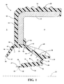
図面をより詳細に参照して、図1および2は、本発明の一局面に従って構成されたラジアル軸封止を例示している。以下、このラジアル軸封止を軸封止10と称する。限定することなく例示として、この軸封止は、クランク室のような装置における応用に適している。図2に示すように、軸封止10は、クランク室のようなハウジング16に設置されると、ハウジング16のボア14を通って延在する回転軸12の周りを密封するラジアル軸封止組立体13を形成するように構成されている。別の方法として、軸封止10をキャリアハウジング内に設置した後、キャリアハウジングおよび10軸封止をエンジンに取付けることもできる。図1および図2を参照して、軸封止10は、軸封止10が設置されるときの向きに関連するオイル側Oと、軸方向に対向する空気側Aとを有する。オイル側Oは、クランク室16の内部に面しており、空気側Aは、オイル側Oから外部環境に向かって面している。軸封止10は、ケースなどの取付部を備えている。取付部は、コアまたはカラー18とも呼ばれ、好ましくは金属製環状構造または金属製リング状構造として形成される。取付部には、エラストマー封止材20が取付けられる。エラストマー封止材20は、軸方向に延在する封止リップ24を有するエラストマー封止本体22の少なくとも一部を形成する。封止リップ24は、使用中に軸12との接触の動的摩擦が低いため、軸12と封止リップ24との間に低トルクをもたらす。たとえば、新規設置された場合、使用中および使用時のトルクは、約0.07〜0.35N*m(ニュートンメートル)である。したがって、軸封止10による摩擦損失が最小限であるため、エンジンの効率の損失は、最小限に抑えられる。
DETAILED DESCRIPTION OF PREFERRED EMBODIMENTS Referring more particularly to the drawings, FIGS. 1 and 2 illustrate a radial shaft seal constructed in accordance with an aspect of the present invention. Hereinafter, this radial shaft seal is referred to as a
環状の金属カラー18は、リング状であってもよく、または当技術分野で知られているように、特定の用途の要求に応じて、例として、C字形、S字形または図示されたL字形の任意の構成にすることもできる。図示された金属カラー18は、少なくとも径方向外側に面する表面26上において、弾性封止材20により部分的に覆われている。クランク室16のボア14内に快適な流体密封設置を提供するために、弾性封止材20の輪郭に起伏30を設けることができる。金属コア18から径方向内側へ延在する封止本体22の中央部23を形成するために、封止本体22の封止材20は、金属コア18の内側表面32の周囲から径方向内側へ延在する。コア18と封止本体22とは比較的剛性であるが、封止材20は、封止リップ24を形成するのに充分な弾力性を有する。
The
封止リップ24は、設置されていないの弛緩状態(図1)にあるとき、たとえば軸封止10の水平中心軸33から約1〜10°の角度で若干傾斜した向きに延在しており、径方向内側に面する環状の封止面34と、オイル側端部38と空気側自由端部39との間に延在しかつ径方向外側に面する反対側の裏当て面36とを有する。封止面34は、自由状態にあるとき、オイル側端部38で最大の直径を有する。この最大の直径は、軸12の運動面37の外径よりも小さい。よって、軸12の周りに軸封止10の設置が完了した後、封止面34の全体が必ず運動面37と密封係合する関係になる。
When the sealing
封止面34は、軸12の回転時にオイルを軸封止10のオイル側Oに送り込むように機能するリブ状または糸状の流体力学的特徴40を有するように構成することができる。さらに、以下で主要粉塵リップ42と呼ばれる粉塵排除リップは、封止リップ24の空気側端部39から空気側Aに向かって直接延在している。主要粉塵リップ42は、軸封止組立体13の空気側Aからオイル側Oへの汚染物質の侵入を阻止し、さらに、軸封止組立体13のオイル側Oの潤滑油を保持することを容易にする。主要粉塵リップ42は、運動面37と当接するように構成された環状リブ43を有する。少なくとも1つのリブ通気孔44がリブ43に形成されている。図3には、複数のリブ通気孔44が示されている。以下、これらのリブ通気孔を通気孔44と称する。これらの通気孔44は、主要粉塵リップ42のリブ43の周方向周りに互いに等間隔で離間するように示されているが、他の構成も考えられる。空気の通過を可能にするとともに、汚染物質の通過を最小限に抑制するために、通気孔44は、リブ43の内部から径方向外側に向って広がる径方向外側大きくなるV字形の切欠(ノッチ)として形成される。
The sealing
軸封止10はさらに、以下で補助粉塵リップ46と称される環状の補助粉塵排除リップを含む。補助粉塵リップ46は、補助粉塵リップ46の自由端部47と軸12の運動面37との間に密封接触を確立するために、金属コア18の内側面32と隣接する封止本体22の中央部23から空気側に向かって径方向内側へ充分延在している。したがって、補助粉塵リップ46がオイル側Oから、一般に封止リップ24から分岐しており、軸12上に軸封止10を設置するときに、補助粉塵リップ46が主要粉塵リップ42を妨げないことが保証される。さらに、補助粉塵リップ46が空気側Aに向かって延在することは、オイル側からの組立を容易にする。主要粉塵リップ42と同様に、補助粉塵リップ46は、軸方向に沿って自由端部47の内部に延在する少なくとも1つのリップ通気孔48を有する。図3には、複数のリップ通気孔48が示されている。以下、これらのリップ通気孔を通気孔48と称する。これらの通気孔48は、補助粉塵リップ46の周方向周りに互いに等間隔で離間するように示されているが、他の構成も考えられる。図示のように、通気孔44、48の各々は、通気孔44、48のうち2つが軸方向に互いに整列されないように、互いに周方向にオフセットをもって離間する。このようにして、通気孔44、48は、連携して機能することによって、主要封止リップ24の内部およびオイル側Oに真空または正圧の形成を防ぐとともに、連携して機能することによって、汚染物質が侵入する直線経路の形成を回避することにより、空気側Aからオイル側Oへの汚染物質の侵入を阻止する。
The
軸封止10の動作性能をさらに強化するために、補助粉塵リップ46は、中央部23と隣接する環状のヒンジ50を有する。ヒンジ50は、薄くなった厚さを有するように封止材20から形成される。したがって、ヒンジ50は、第1厚さt1を有し、補助粉塵リップ46は、ヒンジ50と直接隣接しかつヒンジ50から径方向内側へ延在する第2厚さt2を有する。t1は、t2よりも小さい(t1<t2)。これにより、軸封止10動作時の回転トルクは最小になる。
In order to further enhance the operational performance of the
環状のブリッジ部52は、封止リップ24を封止本体22と動作可能に連結している。環状ブリッジ部52は、第1ヒンジ54を介して封止リップ24のオイル側端部38に連結され、第2ヒンジ56を介して52に中央部23に連結される。ブリッジ部52は、封止リップ24を径方向に覆う形で第1ヒンジ54から第2ヒンジ56に延在するため、軸封止組立体13の空気側Aに面する環状ポケット58を形成する。第1ヒンジ54および第2ヒンジ56は、ブリッジ部52の厚さt5に対して、それぞれ薄くなった厚さt3およびt4を有する。したがって、相対的厚さ関係では、t3およびt4がt5よりも小さい(t3,t4<t5)。
An
限定することなく例として示された軸封止10は、概ね第1ヒンジ54の上方から延在しかつ封止リップ24およびブリッジ部52から軸封止10のオイル側Oへ向かって軸方向に離れた環状の突起60をさらに有する。突起60は、設置中に封止リップ24およびブリッジ部52の広がりを防止することによって、オイル側からの設置を支援するように構成されている。さらに、突起60は、設置時および使用中に軸の運動面37と接触しないように構成されている。
The
複数の補強リブ(以下、リブ62と称する)は、一枚の材料として封止本体22に成形することができる。リブ62は、組立時および組立中において、組立てを容易にし、封止リップ24の封止面34を軸12の運動面37と適切な密閉関係に維持することを容易にする。リブ62は、ブリッジ部52に沿って軸方向に延在しており、図面において、突出部60の上面または径方向外側に面する表面に沿って、ブリッジ部52の全長に亘って延在し、封止本体22の中央部23で終結すると示されている。リブ62は、組立中にブリッジ部52および主封止リップ24の逆折曲を充分防止するのに任意の適切な数で提供することができる。リブ62は、好ましくは、封止本体22の周囲に互いに等距離で離間している。リブ62の高さは、軸封止10が軸12に設置されたときに、それらが封止本体22から離間するように、設定される。
A plurality of reinforcing ribs (hereinafter referred to as ribs 62) can be formed on the sealing
上記の教示を考慮すると、本発明に多くの修正および変更ができることは明らかである。したがって、理解すべきことは、最終的に許可された請求の範囲に属する本発明は、詳細説明以外の方法で実施することが可能であることである。 Obviously, many modifications and variations of the present invention are possible in light of the above teachings. Accordingly, it is to be understood that the invention falling within the scope of the finally granted claims can be practiced otherwise than as detailed.
Claims (10)
環状の取付部と、
前記取付部に接合された封止本体と、
オイル側端部と空気側自由端部との間に延在する環状の封止面を有する封止リップとを含み、前記封止面は、前記軸に沿って軸方向に延在するように構成され、
ヒンジによって前記封止リップの前記オイル側端部に接続されかつ別のヒンジによって前記封止本体の中央部に接続された環状のブリッジ部を含み、前記ブリッジ部は、前記封止リップを径方向に覆う形で延在し、
前記空気側端部から延在する主要粉塵リップを含み、前記主要粉塵リップは、前記軸の運動面と密封当接するように構成された環状リブを有し、前記環状リブは、少なくとも1つのリブ通気孔を有し、
前記封止本体の前記中央部から、前記軸の前記運動面と密封当接するように構成された自由端部まで延在する補助粉塵リップを含み、前記補助粉塵リップの前記自由端部は、前記環状リブの前記少なくとも1つのリブ通気孔から周方向に離間した少なくとも1つのリップ通気孔を有する、ラジアル軸封止。 A radial shaft seal housed in the housing and installed around the shaft to seal and isolate the oil side of the shaft seal and the air side of the shaft seal,
An annular mounting portion;
A sealing body joined to the mounting portion;
A sealing lip having an annular sealing surface extending between the oil side end and the air side free end, the sealing surface extending in the axial direction along the axis Configured,
An annular bridge portion connected to the oil-side end of the sealing lip by a hinge and connected to the central portion of the sealing body by another hinge, the bridge portion radially extending the sealing lip Extending in the form of covering,
A main dust lip extending from the air side end, the main dust lip having an annular rib configured to sealingly contact the moving surface of the shaft, the annular rib being at least one rib; Have vents,
An auxiliary dust lip extending from the central portion of the sealing body to a free end configured to sealingly contact the motion surface of the shaft, the free end of the auxiliary dust lip being A radial shaft seal having at least one lip vent circumferentially spaced from the at least one rib vent of the annular rib.
中心軸に沿って延在し、運動面を提供する軸と、
ハウジング内に収納され、軸封止のオイル側と軸封止の空気側とを密封隔離するように軸の周りに設置されたラジアル軸封止とを含み、前記ラジアル軸封止は、
環状の取付部と、
前記取付部に接合された封止本体と、
オイル側端部と空気側自由端部との間に延在する環状の封止面を有する封止リップとを含み、前記封止面は、前記軸の前記運動面に沿って軸方向に延在するように構成され、
前記封止リップの前記オイル側端部と前記封止本体の中央部とに接続された環状のブリッジ部を含み、前記ブリッジ部は、前記封止リップを径方向に覆う形で延在し、
前記封止リップの前記空気側端部から延在する主要粉塵リップを含み、前記主要粉塵リップは、前記軸の運動面と密封当接するように構成された環状リブを有し、前記環状リブは、少なくとも1つのリブ通気孔を有し、
前記封止本体の前記中央部から、前記軸の前記運動面と密封当接するように構成された自由端部まで延在する補助粉塵リップを含み、前記補助粉塵リップの前記自由端部は、前記少なくとも1つのリブ通気孔から周方向に離間した少なくとも1つのリップ通気孔を有する、ラジアル軸封止組立体。 A radial shaft sealing assembly,
An axis extending along the central axis and providing a moving surface;
A radial shaft seal housed in a housing and installed around the shaft to seal and isolate the oil side of the shaft seal and the air side of the shaft seal, the radial shaft seal comprising:
An annular mounting portion;
A sealing body joined to the mounting portion;
A sealing lip having an annular sealing surface extending between the oil side end and the air side free end, the sealing surface extending in the axial direction along the motion surface of the shaft. Configured to exist,
Including an annular bridge portion connected to the oil-side end portion of the sealing lip and a central portion of the sealing body, the bridge portion extending in a form of covering the sealing lip in the radial direction;
A main dust lip extending from the air-side end of the sealing lip, the main dust lip having an annular rib configured to sealingly contact the moving surface of the shaft; Having at least one rib vent;
An auxiliary dust lip extending from the central portion of the sealing body to a free end configured to sealingly contact the motion surface of the shaft, the free end of the auxiliary dust lip being A radial shaft sealing assembly having at least one lip vent circumferentially spaced from at least one rib vent.
Applications Claiming Priority (3)
| Application Number | Priority Date | Filing Date | Title |
|---|---|---|---|
| US201261655226P | 2012-06-04 | 2012-06-04 | |
| US61/655,226 | 2012-06-04 | ||
| PCT/US2013/043973 WO2013184611A1 (en) | 2012-06-04 | 2013-06-04 | Radial shaft seal and assembly therewith |
Publications (3)
| Publication Number | Publication Date |
|---|---|
| JP2015518949A JP2015518949A (en) | 2015-07-06 |
| JP2015518949A5 JP2015518949A5 (en) | 2016-07-14 |
| JP6140276B2 true JP6140276B2 (en) | 2017-05-31 |
Family
ID=48672807
Family Applications (1)
| Application Number | Title | Priority Date | Filing Date |
|---|---|---|---|
| JP2015516100A Expired - Fee Related JP6140276B2 (en) | 2012-06-04 | 2013-06-04 | Radial shaft seal and assembly including the same |
Country Status (8)
| Country | Link |
|---|---|
| US (1) | US8955849B2 (en) |
| EP (1) | EP2855984B1 (en) |
| JP (1) | JP6140276B2 (en) |
| KR (1) | KR102051171B1 (en) |
| CN (1) | CN104620029B (en) |
| BR (1) | BR112014030240A2 (en) |
| WO (1) | WO2013184611A1 (en) |
| ZA (1) | ZA201408842B (en) |
Families Citing this family (8)
| Publication number | Priority date | Publication date | Assignee | Title |
|---|---|---|---|---|
| US10190637B2 (en) * | 2015-03-09 | 2019-01-29 | Ntn Corporation | Sealed bearing assembly |
| CN106438715B (en) | 2015-08-07 | 2020-03-17 | 舍弗勒技术股份两合公司 | Sealing structure for bearing |
| JP6836152B2 (en) * | 2017-01-26 | 2021-02-24 | Ntn株式会社 | Mold for compression vulcanization of rolling bearing seals and manufacturing method of rolling bearing seals |
| WO2020080408A1 (en) * | 2018-10-18 | 2020-04-23 | Nok株式会社 | Sealing device |
| CN109253259A (en) * | 2018-10-23 | 2019-01-22 | 舍弗勒技术股份两合公司 | sealing device and bearing |
| CN111853243B (en) * | 2019-04-29 | 2024-09-03 | 舍弗勒技术股份两合公司 | Sealing element |
| US11796063B2 (en) | 2021-05-27 | 2023-10-24 | Caterpillar Inc. | Seal assembly for rotatable shaft having ventilated dust seal with debris-blocking filter |
| US12031631B1 (en) | 2023-02-01 | 2024-07-09 | Caterpillar Inc. | Dynamically vented crankshaft seal and systems and methods thereof |
Family Cites Families (24)
| Publication number | Priority date | Publication date | Assignee | Title |
|---|---|---|---|---|
| US2823051A (en) * | 1955-01-31 | 1958-02-11 | Federal Mogul Bower Bearings | Seals |
| US3356376A (en) | 1964-05-11 | 1967-12-05 | Federal Mogul Corp | Axle seal |
| US3534969A (en) | 1966-09-27 | 1970-10-20 | Gen Motors Corp | Seal |
| US3822890A (en) | 1973-01-15 | 1974-07-09 | Roulements Soc Nouvelle | Bearing seals |
| US4033593A (en) | 1976-06-28 | 1977-07-05 | Westinghouse Electric Corporation | Seal for large annular openings |
| US4258927A (en) | 1978-12-13 | 1981-03-31 | Garlock Inc. | Shaft seal with retractable polytetrafluoroethylene-lined sealing lip |
| US4243232A (en) * | 1979-10-29 | 1981-01-06 | Garlock Inc. | One-piece oil seal and boot seal |
| US4616836A (en) | 1983-04-13 | 1986-10-14 | Chicago Rawhide Mfg. Co. | Reverse lip positive venting seal |
| US4556225A (en) | 1983-04-13 | 1985-12-03 | Chicago Rawhide Mfg. Co. | Reverse lip positive venting seal |
| US5024449A (en) * | 1985-12-19 | 1991-06-18 | The Timken Company | Seal assembly for use with an overhang |
| JPH0575562U (en) * | 1992-03-16 | 1993-10-15 | 株式会社豊田自動織機製作所 | Crankshaft oil seal structure |
| DE19518577C2 (en) | 1995-05-20 | 1998-07-09 | Freudenberg Carl Fa | Radial shaft seal |
| US6029980A (en) | 1997-09-18 | 2000-02-29 | Freudenberg-Nok General Partnership | Fluid side contamination exclusion sealing lip for radial shaft seals |
| US6053501A (en) | 1998-04-14 | 2000-04-25 | Morgan Construction Company | Neck seal |
| FR2791390B1 (en) * | 1999-03-26 | 2001-06-29 | Hutchinson | DRILLING HEAD HAVING A CONES BIT |
| CA2638748A1 (en) * | 1999-07-27 | 2001-02-01 | Northeast Equipment, Inc. D/B/A Delta Mechanical Seals | Mechanical split seal |
| BE1013600A3 (en) | 2000-07-19 | 2002-04-02 | Idees & Technologies | Door frame and / or window. |
| US20050073110A1 (en) | 2003-10-07 | 2005-04-07 | James Armour | Neck seal for rolling mill oil film bearing |
| JP2005163815A (en) * | 2003-11-28 | 2005-06-23 | Ntn Corp | Bearing with sealing |
| EP1729046B1 (en) | 2004-03-23 | 2016-09-28 | Nok Corporation | Sealing device with rotation detecting element |
| US7467796B2 (en) | 2004-08-12 | 2008-12-23 | Morgan Construction, Company | Bearing seal with flexible lip |
| EP2382407B1 (en) * | 2009-01-28 | 2018-10-24 | Federal-Mogul Corporation | Radial shaft seal, radial shaft seal assembly and method of installation |
| CN103502706B (en) * | 2011-03-17 | 2016-04-20 | 费德罗-莫格尔公司 | Low torque radial shaft seal assembly |
| CN106662252B (en) * | 2014-08-04 | 2018-08-14 | Nok株式会社 | Sealing device |
-
2013
- 2013-06-04 KR KR1020147035256A patent/KR102051171B1/en not_active Expired - Fee Related
- 2013-06-04 EP EP13730977.9A patent/EP2855984B1/en not_active Not-in-force
- 2013-06-04 WO PCT/US2013/043973 patent/WO2013184611A1/en active Application Filing
- 2013-06-04 BR BR112014030240A patent/BR112014030240A2/en not_active IP Right Cessation
- 2013-06-04 JP JP2015516100A patent/JP6140276B2/en not_active Expired - Fee Related
- 2013-06-04 US US13/909,874 patent/US8955849B2/en not_active Expired - Fee Related
- 2013-06-04 CN CN201380041066.9A patent/CN104620029B/en not_active Expired - Fee Related
-
2014
- 2014-12-02 ZA ZA2014/08842A patent/ZA201408842B/en unknown
Also Published As
| Publication number | Publication date |
|---|---|
| ZA201408842B (en) | 2015-12-23 |
| CN104620029B (en) | 2016-05-04 |
| US8955849B2 (en) | 2015-02-17 |
| US20140042709A1 (en) | 2014-02-13 |
| WO2013184611A1 (en) | 2013-12-12 |
| KR102051171B1 (en) | 2019-12-02 |
| BR112014030240A2 (en) | 2017-06-27 |
| CN104620029A (en) | 2015-05-13 |
| JP2015518949A (en) | 2015-07-06 |
| KR20150017737A (en) | 2015-02-17 |
| EP2855984B1 (en) | 2016-06-22 |
| EP2855984A1 (en) | 2015-04-08 |
Similar Documents
| Publication | Publication Date | Title |
|---|---|---|
| JP6140276B2 (en) | Radial shaft seal and assembly including the same | |
| US20090127796A1 (en) | Sealing device | |
| CN106662253B (en) | Sealing structure | |
| EP2881631B1 (en) | Sealing device | |
| JP6000845B2 (en) | Sealing device | |
| JP6043304B2 (en) | Low torque radial shaft seal assembly | |
| US10208802B2 (en) | Sealing device | |
| JP2014517234A (en) | Radial shaft seal, radial shaft seal assembly and method of installation | |
| JP6372256B2 (en) | Oil seal | |
| JP2015518949A5 (en) | ||
| JP6428034B2 (en) | Oil seal | |
| JP6231072B2 (en) | Radial shaft seal with static and hydrodynamic sealing function | |
| US8573602B2 (en) | Radial shaft seal with dust exclusion and hydrodynamic sealing feature | |
| JP5354196B2 (en) | Center bearing support | |
| JP2006336734A (en) | Rolling bearing with sealing device | |
| JP5311044B2 (en) | Sealing device | |
| KR101874270B1 (en) | Sealing structure | |
| JP5660372B2 (en) | Sealing device | |
| JP2007247708A (en) | Seal with shaft | |
| JP2008175301A (en) | Rolling bearing with seal device | |
| JP6405777B2 (en) | Oil seal | |
| JP6000833B2 (en) | Sealing device | |
| JP2016148385A (en) | Sealing device | |
| JP2009138787A (en) | Sealing device | |
| CN110268184A (en) | Rotary induction and crankshaft assembly |
Legal Events
| Date | Code | Title | Description |
|---|---|---|---|
| A521 | Request for written amendment filed |
Free format text: JAPANESE INTERMEDIATE CODE: A523 Effective date: 20160525 |
|
| A621 | Written request for application examination |
Free format text: JAPANESE INTERMEDIATE CODE: A621 Effective date: 20160525 |
|
| A977 | Report on retrieval |
Free format text: JAPANESE INTERMEDIATE CODE: A971007 Effective date: 20170208 |
|
| A131 | Notification of reasons for refusal |
Free format text: JAPANESE INTERMEDIATE CODE: A131 Effective date: 20170214 |
|
| A521 | Request for written amendment filed |
Free format text: JAPANESE INTERMEDIATE CODE: A523 Effective date: 20170323 |
|
| TRDD | Decision of grant or rejection written | ||
| A01 | Written decision to grant a patent or to grant a registration (utility model) |
Free format text: JAPANESE INTERMEDIATE CODE: A01 Effective date: 20170404 |
|
| A61 | First payment of annual fees (during grant procedure) |
Free format text: JAPANESE INTERMEDIATE CODE: A61 Effective date: 20170428 |
|
| R150 | Certificate of patent or registration of utility model |
Ref document number: 6140276 Country of ref document: JP Free format text: JAPANESE INTERMEDIATE CODE: R150 |
|
| R250 | Receipt of annual fees |
Free format text: JAPANESE INTERMEDIATE CODE: R250 |
|
| LAPS | Cancellation because of no payment of annual fees |