JP6139529B2 - Dialysate flow control - Google Patents
Dialysate flow control Download PDFInfo
- Publication number
- JP6139529B2 JP6139529B2 JP2014527677A JP2014527677A JP6139529B2 JP 6139529 B2 JP6139529 B2 JP 6139529B2 JP 2014527677 A JP2014527677 A JP 2014527677A JP 2014527677 A JP2014527677 A JP 2014527677A JP 6139529 B2 JP6139529 B2 JP 6139529B2
- Authority
- JP
- Japan
- Prior art keywords
- dialysate
- blood
- dialyzer
- control factor
- change
- Prior art date
- Legal status (The legal status is an assumption and is not a legal conclusion. Google has not performed a legal analysis and makes no representation as to the accuracy of the status listed.)
- Active
Links
Images


Classifications
-
- A—HUMAN NECESSITIES
- A61—MEDICAL OR VETERINARY SCIENCE; HYGIENE
- A61M—DEVICES FOR INTRODUCING MEDIA INTO, OR ONTO, THE BODY; DEVICES FOR TRANSDUCING BODY MEDIA OR FOR TAKING MEDIA FROM THE BODY; DEVICES FOR PRODUCING OR ENDING SLEEP OR STUPOR
- A61M1/00—Suction or pumping devices for medical purposes; Devices for carrying-off, for treatment of, or for carrying-over, body-liquids; Drainage systems
- A61M1/14—Dialysis systems; Artificial kidneys; Blood oxygenators ; Reciprocating systems for treatment of body fluids, e.g. single needle systems for hemofiltration or pheresis
- A61M1/16—Dialysis systems; Artificial kidneys; Blood oxygenators ; Reciprocating systems for treatment of body fluids, e.g. single needle systems for hemofiltration or pheresis with membranes
- A61M1/1601—Control or regulation
- A61M1/1603—Regulation parameters
- A61M1/1605—Physical characteristics of the dialysate fluid
-
- A—HUMAN NECESSITIES
- A61—MEDICAL OR VETERINARY SCIENCE; HYGIENE
- A61M—DEVICES FOR INTRODUCING MEDIA INTO, OR ONTO, THE BODY; DEVICES FOR TRANSDUCING BODY MEDIA OR FOR TAKING MEDIA FROM THE BODY; DEVICES FOR PRODUCING OR ENDING SLEEP OR STUPOR
- A61M1/00—Suction or pumping devices for medical purposes; Devices for carrying-off, for treatment of, or for carrying-over, body-liquids; Drainage systems
- A61M1/14—Dialysis systems; Artificial kidneys; Blood oxygenators ; Reciprocating systems for treatment of body fluids, e.g. single needle systems for hemofiltration or pheresis
- A61M1/16—Dialysis systems; Artificial kidneys; Blood oxygenators ; Reciprocating systems for treatment of body fluids, e.g. single needle systems for hemofiltration or pheresis with membranes
- A61M1/1601—Control or regulation
- A61M1/1615—Control or regulation using measurements made at different flow rates
-
- A—HUMAN NECESSITIES
- A61—MEDICAL OR VETERINARY SCIENCE; HYGIENE
- A61M—DEVICES FOR INTRODUCING MEDIA INTO, OR ONTO, THE BODY; DEVICES FOR TRANSDUCING BODY MEDIA OR FOR TAKING MEDIA FROM THE BODY; DEVICES FOR PRODUCING OR ENDING SLEEP OR STUPOR
- A61M1/00—Suction or pumping devices for medical purposes; Devices for carrying-off, for treatment of, or for carrying-over, body-liquids; Drainage systems
- A61M1/36—Other treatment of blood in a by-pass of the natural circulatory system, e.g. temperature adaptation, irradiation ; Extra-corporeal blood circuits
- A61M1/3607—Regulation parameters
- A61M1/3609—Physical characteristics of the blood, e.g. haematocrit, urea
-
- A—HUMAN NECESSITIES
- A61—MEDICAL OR VETERINARY SCIENCE; HYGIENE
- A61M—DEVICES FOR INTRODUCING MEDIA INTO, OR ONTO, THE BODY; DEVICES FOR TRANSDUCING BODY MEDIA OR FOR TAKING MEDIA FROM THE BODY; DEVICES FOR PRODUCING OR ENDING SLEEP OR STUPOR
- A61M2205/00—General characteristics of the apparatus
- A61M2205/33—Controlling, regulating or measuring
- A61M2205/3317—Electromagnetic, inductive or dielectric measuring means
-
- A—HUMAN NECESSITIES
- A61—MEDICAL OR VETERINARY SCIENCE; HYGIENE
- A61M—DEVICES FOR INTRODUCING MEDIA INTO, OR ONTO, THE BODY; DEVICES FOR TRANSDUCING BODY MEDIA OR FOR TAKING MEDIA FROM THE BODY; DEVICES FOR PRODUCING OR ENDING SLEEP OR STUPOR
- A61M2205/00—General characteristics of the apparatus
- A61M2205/33—Controlling, regulating or measuring
- A61M2205/3324—PH measuring means
-
- A—HUMAN NECESSITIES
- A61—MEDICAL OR VETERINARY SCIENCE; HYGIENE
- A61M—DEVICES FOR INTRODUCING MEDIA INTO, OR ONTO, THE BODY; DEVICES FOR TRANSDUCING BODY MEDIA OR FOR TAKING MEDIA FROM THE BODY; DEVICES FOR PRODUCING OR ENDING SLEEP OR STUPOR
- A61M2205/00—General characteristics of the apparatus
- A61M2205/33—Controlling, regulating or measuring
- A61M2205/3368—Temperature
-
- A—HUMAN NECESSITIES
- A61—MEDICAL OR VETERINARY SCIENCE; HYGIENE
- A61M—DEVICES FOR INTRODUCING MEDIA INTO, OR ONTO, THE BODY; DEVICES FOR TRANSDUCING BODY MEDIA OR FOR TAKING MEDIA FROM THE BODY; DEVICES FOR PRODUCING OR ENDING SLEEP OR STUPOR
- A61M2205/00—General characteristics of the apparatus
- A61M2205/50—General characteristics of the apparatus with microprocessors or computers
Landscapes
- Health & Medical Sciences (AREA)
- Heart & Thoracic Surgery (AREA)
- Vascular Medicine (AREA)
- Urology & Nephrology (AREA)
- Hematology (AREA)
- Veterinary Medicine (AREA)
- Anesthesiology (AREA)
- Biomedical Technology (AREA)
- Engineering & Computer Science (AREA)
- Life Sciences & Earth Sciences (AREA)
- Animal Behavior & Ethology (AREA)
- General Health & Medical Sciences (AREA)
- Public Health (AREA)
- Emergency Medicine (AREA)
- Cardiology (AREA)
- Physics & Mathematics (AREA)
- Fluid Mechanics (AREA)
- External Artificial Organs (AREA)
Description
本発明は、透析装置における透析液流を制御する方法および装置に関する。 The present invention relates to a method and apparatus for controlling dialysate flow in a dialysis machine.
ここで用いられる透析装置という語は、特に体外血液治療用の装置を指し、例えば血液透析や限外ろ過用に構成された装置を指す。 As used herein, the term dialysis device refers specifically to a device for extracorporeal blood treatment, such as a device configured for hemodialysis or ultrafiltration.
血液透析中は、透析装置における患者の血液は、透析器の血液室を通じて体外血液循環に導かれる。血液室は、透析器の透析室から半透過性の膜によって隔てられている。透析室は、透析液により灌流されている。透析液は、血液電解質を含んでおり、その濃度は、健常者の血液中における濃度に対応している。治療中は、血液が半透過性の膜の一方の側を所定の流量で流れ、透析液が当該膜の逆側を所定の流量で流れる。血液と透析液の流れる向きは互いに逆であることが一般的である。尿により排出されるべき物質は、血液室から膜を通じて透析室へ拡散する。同時に、血液と透析液中に存在する電解質は、高濃度の室から低濃度の室へ向かって拡散する。 During hemodialysis, the patient's blood in the dialyzer is directed to extracorporeal blood circulation through the blood chamber of the dialyzer. The blood chamber is separated from the dialyzer's dialysis chamber by a semi-permeable membrane. The dialysis chamber is perfused with dialysate. The dialysate contains a blood electrolyte, and its concentration corresponds to the concentration in the blood of a healthy person. During treatment, blood flows at a predetermined flow rate on one side of a semi-permeable membrane and dialysate flows at a predetermined flow rate on the opposite side of the membrane. In general, the flow directions of blood and dialysate are opposite to each other. Substances to be excreted by urine diffuse from the blood chamber through the membrane to the dialysis chamber. At the same time, the electrolyte present in the blood and dialysate diffuses from the high concentration chamber toward the low concentration chamber.
また、血液は、透析器の半透過性膜に圧力勾配を形成することにより、脱水されうる。結果として、透析室の側へ、血液から水が押し出される。この処理は、限外ろ過と呼ばれている。 Blood can also be dehydrated by creating a pressure gradient in the semipermeable membrane of the dialyzer. As a result, water is pushed out of the blood toward the dialysis chamber. This process is called ultrafiltration.
透析装置すなわち血液治療における透析器の有効性は、透析液流の大きさ、すなわち透析液の流量にも依存している。透析液の流量が高ければ、血液治療の有効性を最大限にできるが、透析液およびエネルギーの消費増にもつながる。 The effectiveness of a dialyzer or dialyzer in blood treatment also depends on the size of the dialysate flow, ie the dialysate flow rate. A high dialysate flow rate can maximize the effectiveness of blood treatment, but also leads to increased consumption of dialysate and energy.
したがって、血液治療の効果をできるだけ高めつつ、透析液とエネルギーの消費を許容範囲内に抑えるために、透析装置における透析液流の量を特定することが望まれており、これが本発明の目的である。また、そのような透析液流の量の特定が、使用される透析器の種別、血流、特定の患者パラメータに係る知識(例えば、再循環の存在)に関わりなくなされうることがさらに望まれている。 Therefore, it is desirable to specify the amount of dialysate flow in the dialyzer in order to keep the consumption of dialysate and energy within an acceptable range while enhancing the effect of blood treatment as much as possible, which is the purpose of the present invention. is there. It is further desirable that identification of such dialysate flow volume can be made regardless of the type of dialyzer used, blood flow, and knowledge of specific patient parameters (eg, the presence of recirculation). ing.
本発明によれば、透析液流を制御する方法において、透析器の血液室が血液で灌流されるとともに、半透過性の膜により当該血液室と隔離された透析室が透析液で灌流される。透析液流を制御するために、透析液または血液の特性変化、あるいは透析液の流量変化に起因する制御因子の値の変化が特定される。制御因子は、透析器を通じた物質交換、すなわち透析器の有効性の尺度である。制御因子の値の変化が臨界を超えると前記透析液の流量が増加される。他方、制御因子の値の変化が当該臨界に達しないと透析液の流量が減少される。 According to the present invention, in the method of controlling the dialysate flow, the blood chamber of the dialyzer is perfused with blood, and the dialysis chamber isolated from the blood chamber by a semipermeable membrane is perfused with dialysate. . In order to control the dialysate flow, a change in the characteristics of the dialysate or blood or a change in the value of the control factor due to a change in the flow rate of the dialysate is identified. The controlling factor is a measure of substance exchange through the dialyzer, ie the effectiveness of the dialyzer. When the change in the value of the control factor exceeds the critical value, the flow rate of the dialysate is increased. On the other hand, if the change in the value of the control factor does not reach the critical value, the dialysate flow rate is reduced.
本発明によれば、透析液流を制御する装置は、
血液を灌流する血液室と、半透過性の膜により前記血液室と隔離されており、透析液が灌流される透析室とを備えている透析器と、
前記透析室を通過する透析液流を生成する手段と、
前記透析器を通じた物質交換、すなわち前記透析器の有効性の尺度である制御因子を特定するユニットと、
前記透析液または前記血液の特性変化、あるいは前記透析液の流量変化に起因して制御因子の値が変化し、臨界から外れると、前記透析器の前記透析室を通過する前記透析液流を制御する制御設備と、
を備えており、
前記制御設備は、前記制御因子の値の変化が前記臨界を上回ると前記透析液の流量を増加させ、前記制御因子の値の変化が前記臨界を下回ると前記透析液の流量を減少させるように、前記透析液流を生成する手段に指示を行なう。
According to the invention, the device for controlling the dialysate flow comprises:
A dialyzer comprising a blood chamber that perfuses blood and a dialysis chamber that is separated from the blood chamber by a semi-permeable membrane and into which dialysate is perfused;
Means for generating a dialysate flow through the dialysis chamber;
A unit for identifying a control factor that is a measure of substance exchange through the dialyzer, i.e., the effectiveness of the dialyzer;
When the value of the control factor changes due to a change in the characteristics of the dialysate or blood, or a change in the flow rate of the dialysate, and controls the flow of the dialysate passing through the dialysis chamber of the dialyzer Control equipment to
With
The control equipment increases the flow rate of the dialysate when the change in the value of the control factor exceeds the criticality, and decreases the flow rate of the dialysate when the change in the value of the control factor falls below the criticality. Instruct the means for generating the dialysate flow.
前記制御因子の値の変化が前記透析液の流量変化に起因する場合、前記制御因子は、前記流量変化の前後に対応する複数の値から得られる比または差を含んでいることが好ましい。この場合、前記複数の値は、前記透析器の下流における前記透析液または前記血液の特性値である。すなわち、前記比または差を特定するために、前記透析液流の変化は既に生じている前記透析器の出口における前記透析液または前記血液の特性値と、前記透析液流の変化が未だ生じていない前記透析器の入口における前記透析液または前記血液の特性値とが使用される。 When the change in the value of the control factor is caused by the change in the flow rate of the dialysate, the control factor preferably includes a ratio or difference obtained from a plurality of values corresponding to before and after the change in the flow rate. In this case, the plurality of values are characteristic values of the dialysate or the blood downstream of the dialyzer. That is, in order to identify the ratio or difference, a change in the dialysate flow has already occurred. A characteristic value of the dialysate or blood at the outlet of the dialyzer and a change in the dialysate flow have not yet occurred. The dialysate or blood characteristic value at the inlet of the dialyzer is not used.
前記制御因子の値の変化が前記透析液または前記血液の特性の変化に起因する場合、前記制御因子は、前記透析器の上流および下流における当該特性より得られる比または差を含んでいることが好ましい。すなわち、透析器の下流における透析液または血液の特性値と、透析器の上流における透析液または血液の特性値とにより、透析液の特性変化について比または差が特定されうる。したがって、血液の特性変化についても同様に、透析器の下流における透析液または血液の特性値と、透析器の上流における透析液または血液の特性値とにより、比または差が特定されうる。制御因子は、透析器の上流における透析液の特性値に対する透析器の下流における透析液の特性値の比を含んでいることが好ましい。制御因子に係る表現に含まれている「差」は、透析器の下流における透析液の特性値および透析器の上流における透析液の特性値から得られることが好ましい。 If the change in the value of the control factor is due to a change in the characteristics of the dialysate or the blood, the control factor may include a ratio or difference obtained from the characteristics upstream and downstream of the dialyzer preferable. That is, the ratio or difference of the dialysate characteristic change can be specified by the dialysate or blood characteristic value downstream of the dialyzer and the dialysate or blood characteristic value upstream of the dialyzer. Accordingly, the ratio or difference can be specified similarly for the characteristic change of blood by the characteristic value of the dialysate or blood downstream of the dialyzer and the characteristic value of the dialysate or blood upstream of the dialyzer. The control factor preferably includes the ratio of the characteristic value of the dialysate downstream of the dialyzer to the characteristic value of the dialysate upstream of the dialyzer. The “difference” included in the expression relating to the control factor is preferably obtained from the characteristic value of the dialysate downstream of the dialyzer and the characteristic value of the dialysate upstream of the dialyzer.
前記透析液の前記特性は、当該透析液の導電率または温度であることが好ましい。また、前記血液の前記特性は、当該血液の導電率または温度であることが好ましい。 The characteristic of the dialysate is preferably the conductivity or temperature of the dialysate. Moreover, it is preferable that the said characteristic of the said blood is the electrical conductivity or temperature of the said blood.
前記制御因子の値の変化を特定するために、前記透析液または前記血液の前記特性が、少なくとも時間連続的に変えられることが好ましい。前記制御因子自身の値の変化は、前記透析液流より得られる前記制御因子の微分値により特定されることが好ましい。 In order to identify changes in the value of the control factor, it is preferred that the properties of the dialysate or the blood are changed at least continuously over time. The change in the value of the control factor itself is preferably specified by a differential value of the control factor obtained from the dialysate flow.
前記臨界は、毎分100mlの透析液流量の変化に対する前記制御因子の値の10、11、12、13、14、15、16、17、18、19、または20%の値の許容誤差に対応していることが好ましい。ここで前記許容誤差の範囲は、毎分100mlの透析液流量の変化に対する前記制御因子の値の1%であることが好ましい。この場合、臨界が毎分100mlの透析液流量の変化に対する前記制御因子の値の10%である場合、当該臨界の範囲は、毎分100mlの透析液流量の変化に対する前記制御因子の値の9.5%から10.5%となる。あるいは、前記許容誤差の範囲はゼロとされうる。この場合、臨界は、毎分100mlの透析液流量の変化に対する前記制御因子の値の10、11、12、13、14、15、16、17、18、19、または20%の値に一致する。 The criticality corresponds to a tolerance of 10, 11, 12, 13, 14, 15, 16, 17, 18, 19, or 20% of the value of the control factor for a change in dialysate flow rate of 100 ml per minute It is preferable. Here, the range of the allowable error is preferably 1% of the value of the control factor with respect to a change in the dialysate flow rate of 100 ml per minute. In this case, if the criticality is 10% of the value of the control factor for a change in dialysate flow rate of 100 ml per minute, the critical range is 9 of the value of the control factor for a change in dialysate flow rate of 100 ml per minute. .5% to 10.5%. Alternatively, the tolerance range may be zero. In this case, the criticality corresponds to a value of 10, 11, 12, 13, 14, 15, 16, 17, 18, 19, or 20% of the control factor value for a change in dialysate flow rate of 100 ml per minute. .
本発明に係る透析液流を制御する装置は、体外血液治療装置(例えば透析装置)に用いられることが好ましい。 The apparatus for controlling the dialysate flow according to the present invention is preferably used for an extracorporeal blood treatment apparatus (for example, a dialysis apparatus).
以下、図面と関連付けて本発明がより詳細に説明される。 Hereinafter, the present invention will be described in more detail with reference to the drawings.
上式で表される制御因子は、透析器の有効性の尺度として使える。ここでQdは、透析器中の透析液流を示し、Ad,inとAd,outは、透析液の特性(例えば、透析器の上流および下流における透析液の導電性や温度)を示す。Ad,out(0)は、浄化能力が消失した場合(例えば血流が消失した場合)の透析液の特性値を示す。浄化能力が存在する場合は、透析液流が増加すると制御因子kdが増加する。しかしながら、制御因子kdのゲインは常に減少する。すなわち、透析液流の増加により透析液とエネルギーの消費が急速に増加すると、透析器の有効性をさらに高めようとしても、ある臨界値からの透析液流のさらなる増加が望めなくなる。 The control factor expressed by the above equation can be used as a measure of the effectiveness of the dialyzer. Here, Q d indicates the dialysate flow in the dialyzer, and A d, in and A d, out indicate the characteristics of the dialysate (for example, the conductivity and temperature of the dialysate upstream and downstream of the dialyzer). Show. A d, out (0) indicates the characteristic value of the dialysate when the purification ability is lost (for example, when the blood flow is lost). In the presence of purification capacity, the control factor k d increases as the dialysate flow increases. However, the gain of the control factor k d always decreases. That is, if the dialysate and energy consumption increase rapidly due to an increase in dialysate flow, no further increase in dialysate flow from a certain critical value can be expected even if the effectiveness of the dialyzer is further increased.
制御因子kdを透析液流量Qdで割った商を透析液流量Qdで微分すると、制御因子kd/Qdの変化が得られる。すなわち、透析液流量Qdの変化による透析器の有効性の規格化ゲインが得られる。 When the quotient obtained by dividing the control factor k d dialysate flow rate Q d is differentiated in dialysate flow rate Q d, change of the control factor k d / Q d is obtained. That is, the normalized gain of the effectiveness of the dialyzer due to changes in dialysate flow rate Q d is obtained.
上式においては、透析器の上流における透析液の特性Ad,inが透析液流量Qdに依存していないことがわかる。当該透析液の特性が、例えば導電性である場合、例えば透析器に注入される電解液の量が変化しても、透析器の上流における透析液の導電性の値は一定に維持されうる。この事は、後述するように、特に制御因子の値の変化を特定するために透析液の特性が連続的に変更される場合において重要である。 In the above equation, it can be seen that the characteristic A d, in of the dialysate upstream of the dialyzer does not depend on the dialysate flow rate Q d . When the dialysate has a conductive property, for example, the conductivity value of the dialysate upstream of the dialyzer can be kept constant even if the amount of electrolyte injected into the dialyzer changes, for example. As will be described later, this is particularly important when the characteristics of the dialysate are continuously changed in order to identify changes in the value of the control factor.
また、制御因子kdを透析液流量Qdで割った商を透析液流量Qdで微分する式においては、Ad,out(0)の項は無視できる。これにより微分演算を簡略化できる。 In addition, in the expression for differentiating the quotient obtained by dividing the control factor k d by the dialysate flow rate Q d by the dialysate flow rate Q d , the term A d, out (0) can be ignored. Thereby, the differential operation can be simplified.
血液治療中においては、透析液流は変更され、制御因子kd/Qdの変化が特定される。これにより、透析液流の変化が、注目する透析液流の変化によるものなのか、血液治療中におけるパラメータの変化によるものなのかが特定されうる。制御因子kd/Qdの変化の特定は、透析液流の変化の前後において制御因子kd/Qdを特定することにより、あるいは、制御因子kdを透析液流量Qdで割った商を透析液流量Qdで微分する演算を連続的に行なうことにより、注目する透析液流の変化の範囲内で行ないうる。 During blood treatment, the dialysate flow is changed and changes in the control factor k d / Q d are identified. Thereby, it can be specified whether the change in the dialysate flow is due to the change in the dialysate flow of interest or the change in parameters during blood treatment. It identified a change in the control factor k d / Q d, by specifying the control factor k d / Q d before and after the change in dialysate flow, or by dividing the control factor k d dialysate flow Q d quotient the by performing an operation for differentiating continuously in dialysate flow rate Q d, capable of carrying out within the range of variation in dialysate flow of interest.
そして、予め特定された制御因子の変化が、臨界値あるいは臨界域(上限値と下限値を有する)と比較される。制御因子の変化が臨界値あるいは臨界域の下限値未満であれば、透析液流は減少される。他方、制御因子の変化が臨界値あるいは臨界域の上限値を上回れば、透析液流は増加される。毎分100mlの透析液流の変化に対して制御因子の値の10%〜20%が、臨界値として非常に好ましいことがわかっている。これら臨界値の各々について、対応する許容誤差を定める上限値と下限値が同様に定められうる。許容誤差は、毎分100mlの透析液流の変化に対して制御因子の値の1%となることが好ましい。例えば、毎分100mlの透析液流の変化に対して制御因子の値の20%が臨界値である場合、臨界域の上限値と下限値は、毎分100mlの透析液流の変化に対して制御因子の値の19.5%と20.5%に対応する。このような制御により、透析器の有効性に応じて透析液流が最適化されるだけでなく、透析液とエネルギーの消費も最適化される。 Then, the change of the control factor specified in advance is compared with a critical value or a critical range (having an upper limit value and a lower limit value). If the change in the control factor is less than the critical value or the lower limit of the critical range, the dialysate flow is reduced. On the other hand, if the change of the control factor exceeds the critical value or the upper limit value of the critical region, the dialysate flow is increased. It has been found that 10% to 20% of the value of the control factor for the change in dialysate flow of 100 ml per minute is highly preferred as the critical value. For each of these critical values, an upper limit value and a lower limit value that define a corresponding tolerance can be similarly determined. The tolerance is preferably 1% of the control factor value for a change in dialysate flow of 100 ml per minute. For example, if 20% of the control factor value is a critical value for a change in the dialysate flow of 100 ml per minute, the upper and lower limits of the critical region will be the change in the dialysate flow of 100 ml per minute. This corresponds to 19.5% and 20.5% of the value of the control factor. Such control not only optimizes dialysate flow according to dialyzer effectiveness, but also optimizes dialysate and energy consumption.
ある透析液流に対して、患者の血液の特性についての対応する比率が得られる。血液の特性の例としては、導電性、温度、マーカ物質(Naイオン、尿素、β2−ミクログロブリンなど)の濃度が挙げられる。当該比率は、透析器の上流(入口)における透析液の特性に対応する値に対する、透析器の下流(出口)における透析液の特性に対応する値の比率である。透析液流の変化は、透析器の出口における透析液の特性に対応する値を変化させる。よって、注目する透析液流の変化の前後で制御因子を特定することにより、注目する透析液流の変化に基づく制御因子の変化が特定されうる。なお、上記透析液の特性に対応する値は、当該透析液が透析器を出た後に特定される。その後、注目する透析液流の変化がいつ透析器の出口に及んだのかが特定される必要がある。すなわち、ある透析液流の変化に対して制御因子の変化を対応付けできるようにするために、特定の透析液流に対する透析器の流体的な応答遅れを知る必要がある。透析器の流体的な応答遅れを特定する方法は公知である。注目する透析液流の変化は、一時的なものでありうる。すなわち、透析液の流量変化は、周期的あるいはパルス的にごく短時間だけ継続すればよい。 For a given dialysate stream, a corresponding ratio for the patient's blood characteristics is obtained. Examples of blood characteristics include conductivity, temperature, and concentration of marker substances (Na ions, urea, β2-microglobulin, etc.). The ratio is the ratio of the value corresponding to the characteristic of the dialysate downstream (outlet) of the dialyzer to the value corresponding to the characteristic of the dialysate upstream (inlet) of the dialyzer. The change in dialysate flow changes the value corresponding to the dialysate characteristics at the dialyzer outlet. Therefore, by specifying the control factor before and after the change in the dialysate flow of interest, the change in the control factor based on the change in the dialysate flow of interest can be specified. The value corresponding to the characteristics of the dialysate is specified after the dialysate has exited the dialyzer. It then needs to be identified when the dialysate flow change of interest reaches the dialyzer outlet. That is, it is necessary to know the fluid response delay of the dialyzer for a particular dialysate flow so that a change in control factor can be associated with a change in a certain dialysate flow. Methods for identifying dialyzer fluid response delays are known. The noted dialysate flow change may be temporary. That is, the flow rate change of the dialysate may be continued only for a very short time periodically or in a pulse manner.
制御因子を特定するために、注目する透析液流の変化に代えて、透析器に入る前の透析液の特性が連続的に(すなわち周期的に)変更されうる。透析器への進入時における透析液の特性値Ad,inの連続的な変調は、透析器の出口における透析液の特性値Ad,outの変調をもたらす。これにより、定常状態においては、ある時点の透析器の出口において透析液の特性値がどのようなものであるかが判り、透析液流の変化が直ちに透析器の出口における透析液の特性値変化に関連付けられうる。また、透析器の透水性、変調周波数、およびチューブ形状に依存する複合伝達関数を知る必要がない。 Instead of changing the dialysate flow of interest, the characteristics of the dialysate prior to entering the dialyzer can be changed continuously (ie, periodically) to identify the control factor. The continuous modulation of the dialysate characteristic value Ad, in during entry into the dialyzer results in the modulation of the dialysate characteristic value Ad, out at the dialyzer outlet. As a result, in a steady state, it is possible to know what the characteristic value of the dialysate is at the dialyzer outlet at a certain point in time, and the change in the dialysate flow immediately changes the characteristic value of the dialysate at the dialyzer outlet. Can be associated. Also, it is not necessary to know the composite transfer function that depends on the permeability of the dialyzer, the modulation frequency, and the tube shape.
透析液の特性が透析液の導電性あるいは温度である場合、図1は、研究所における(インビトロな)透析治療について、透析器の上流(線C1)と下流(線C2)における透析液の導電性(左縦軸)あるいは温度(右縦軸)の経時変化を示している。透析液流は毎分800mlである。すなわち、透析器に入る透析液の導電性や温度は、透析液に注入される物質(すなわち電解質)の量を変化させるか、透析液に加える熱を変化させることにより、当該変化とほぼ調和するように変化する。透析液中に含まれる少なくとも1種の電解質濃度の変更や、透析液の熱変調は、患者に対する生理的な害のない範囲内で行われる。 If the dialysate characteristic is dialysate conductivity or temperature , then FIG. 1 shows the dialysate conductivity upstream (line C1) and downstream (line C2) of the dialyzer for (in vitro) dialysis treatment in the laboratory. It shows the change over time in the sex (left vertical axis ) or temperature (right vertical axis) . The dialysate flow is 800 ml per minute . Ie, the conductivity and the temperature of the dialysate entering the dialyzer, or varying the amount of material (i.e., electrolyte) to be injected into the dialysate, by varying the heat applied to the dialysate, generally with the change Change to harmonize. Changes in the concentration of at least one electrolyte contained in the dialysate and thermal modulation of the dialysate are performed within a range that is not physiologically harmful to the patient.
透析器の容積に応じて、異なる物質(すなわち、異なる特性を有する複数の透析液)が透析器内で混合されうる。この混合物は、変調(すなわち、透析器から流出する透析液の導電率あるいは温度の変化)の緩衝をもたらす。これにより、透析器から流出する透析液の導電率あるいは温度の、変調周期および透析器の容積への依存性が抑制される。さらに、変調された透析液の一部は、半透過性膜を通過して体外循環(血流)に至る。これにより、透析器から流出する透析液の導電率あるいは温度の変調がさらに抑制される。変調の抑制は、図1における曲線C1とC2を比べることにより(特に振幅を比較することにより)明らかに認識されうる。 Depending on the volume of the dialyzer, different substances (ie multiple dialysates with different properties) can be mixed in the dialyzer. This mixture provides a buffer of modulation (ie, changes in conductivity or temperature of dialysate exiting the dialyzer). Thereby, the dependence of the conductivity or temperature of the dialysate flowing out of the dialyzer on the modulation period and the volume of the dialyzer is suppressed. Furthermore, a part of the modulated dialysate passes through the semipermeable membrane and reaches the extracorporeal circulation (blood flow). This further suppresses the conductivity or temperature modulation of the dialysate flowing out of the dialyzer. Modulation suppression can be clearly recognized by comparing the curves C1 and C2 in FIG. 1 (especially by comparing the amplitudes).
透析器の上流と下流における透析液の導電率または温度の値は、測定セルにより検出されうる。測定セルからのデータより、透析液流の変化の効果が直接に検出されうる。これにより、透析液流の制御すなわち最適化が非常に迅速に遂行されうる。 The conductivity or temperature value of the dialysate upstream and downstream of the dialyzer can be detected by the measuring cell. From the data from the measuring cell, the effect of changes in the dialysate flow can be directly detected. Thereby, the control or optimization of the dialysate flow can be performed very quickly.
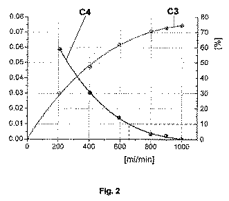
図2に示すように、透析器の上流と下流における透析液の導電率または温度の値の振幅比は、透析液流量の関数(左縦軸に対応する曲線C3)として表される。また、振幅比の相対変化は、透析液流量の関数(右縦軸に対応する曲線C4)として表される。 As shown in FIG. 2, the amplitude ratio of the dialysate conductivity or temperature value upstream and downstream of the dialyzer is expressed as a function of the dialysate flow rate (curve C3 corresponding to the left vertical axis). The relative change in the amplitude ratio is expressed as a function of the dialysate flow rate (curve C4 corresponding to the right vertical axis).
曲線C3は、透析液流量が大きくなるにつれて増加している。よって、透析器の上流と下流における透析液の導電率または温度の値の比は、透析液流量が大きくなるにつれて減少する。したがって、曲線C4は、透析液流量が大きくなるにつれて、振幅比の相対変化は小さくなる。透析液流量の値が毎分約650mlの場合、振幅比の相対変化、すなわち透析器の効果の増分は、わずか10%未満となる。 Curve C3 increases as the dialysate flow rate increases. Thus, the ratio of dialysate conductivity or temperature values upstream and downstream of the dialyzer decreases as the dialysate flow rate increases. Therefore, as for the curve C4, the relative change in the amplitude ratio decreases as the dialysate flow rate increases. With a dialysate flow rate value of about 650 ml per minute, the relative change in amplitude ratio, i.e. the increase in dialyzer effect, is only less than 10%.
透析器の入口における透析液の特性値と出口における透析液の特性値を検出することにより制御因子の変化を特定すること、すなわち、透析器の側で透析液の特性値変化を検出することに代えて、透析器において透析液から血液へ伝えられる特性は、血液側でも測定されうる。すなわち、当該測定は、透析器に入る前と透析器の出口における血液の特性を検出することによりなされうる。例えば、透析器を通じた透析液中の温度ボーラスの血液への移動は、静脈管系内で測定されうる。制御因子は、次式に示すように、治療の有効質量も透析液流量の関数として含んでいる。 To identify the change in the control factor by detecting the characteristic value of the dialysate at the inlet of the dialyzer and the characteristic value of the dialysate at the outlet, that is, to detect the change in the characteristic value of the dialysate on the dialyzer side. Alternatively, the properties transmitted from the dialysate to the blood in the dialyzer can also be measured on the blood side. That is, the measurement can be made by detecting blood characteristics before entering the dialyzer and at the outlet of the dialyzer. For example, the movement of a temperature bolus into the blood through the dialyzer in the dialysate can be measured within the venous system. The control factor also includes the effective mass of treatment as a function of dialysate flow rate, as shown in the following equation.
ここでQbは血流、すなわち血液の流量を示す。Qdは透析器中の透析液流を示す。Ab,inは、透析器の上流における血液の特性(例として導電率または温度)を示す。Ab,outは、透析器の出口における当該血液の特性を示している。Ab,out(0)は、透析器の出口における浄化能力が消失した血液の特性値を示す。 Here Q b represents the blood flow, i.e. the flow rate of the blood. Qd represents the dialysate flow in the dialyzer. A b, in indicates the characteristic of blood upstream of the dialyzer (for example, conductivity or temperature). Ab, out indicates the characteristics of the blood at the outlet of the dialyzer. A b, out (0) represents the characteristic value of blood from which the purification ability at the outlet of the dialyzer has disappeared.
繰り返しになるが、制御因子kbを直接使うのではなく、制御因子kbを血流量Qbで割った商を透析液流量Qdで微分したもの、すなわち透析液流量Qdの変化に伴う制御因子kd/Qdの変化を用いることが有意義である。 Again, not the than using direct regulator k b, with controlled factor k b a differentiated dialysis fluid flow rate Q d and divided by blood flow Q b, that is, changes in dialysate flow rate Q d It is meaningful to use changes in the control factor k d / Q d .
よって、本発明は、透析液の特性を変化させ、血液側において対応する血液の特性変化を検出することにより、透析液流の制御も可能にする。 Therefore, the present invention also enables control of the dialysate flow by changing the characteristics of the dialysate and detecting the corresponding change in blood characteristics on the blood side.
注目する透析液流の変化による制御因子の変化を特定する場合においても必要とされる透析液または血液の特性変化の検出が、透析液側または血液側で行なわれうる。 Detection of a change in the characteristics of the dialysate or blood, which is required even when specifying a change in the control factor due to a change in the dialysate flow of interest, can be performed on the dialysate side or the blood side.
透析器に入る前の透析液の特性変化に代えて制御因子の変化を特定するために、透析器に入る前の血液の特性が連続的に(例えば周期的に)変えられうる。そして、透析器の出口における血液の特性に対する治療効果が、血液側または透析液側で測定されうる。よって、透析器に入る前の血液の特性変化は、患者に負担のないわずかな血液温度の変化からなりうる。透析器に入る前の血液へのヘパリン入力を変化させてもよい。透析液の凝固を防ぐために、透析器に入る前に血液透析ヘパリンまたは抗凝固剤(クエン酸塩)が患者の血液に連続的に加えられる場合、例えばこれらの薬剤を含むシリンジポンプが用いられる。このポンプ(ヘパリンポンプ)の流量は、適宜に変更されうる。さらなる別例として、置換率も変更されうる。ここで適用されることが好ましい前希釈のために、無菌代用剤が透析器に入る前の患者の血液に加えられる。血液中における当該代用剤の成分(例えば、グルコース、ナトリウム、カリウム、マグネシウム、カルシウム、および重炭酸塩)は、血液側から透析液側へ透析器内を通過し、少なくとも間接的に検出される。例えば電解質の場合、導電率測定セルによって検出される。 In order to identify changes in control factors instead of changes in dialysate properties prior to entering the dialyzer, the blood properties prior to entering the dialyzer can be continuously (eg, periodically) changed. The therapeutic effect on the blood characteristics at the outlet of the dialyzer can then be measured on the blood side or dialysate side. Thus, the change in blood characteristics before entering the dialyzer can consist of a slight change in blood temperature that does not burden the patient. The heparin input to the blood before entering the dialyzer may be varied. If hemodialysis heparin or an anticoagulant (citrate) is continuously added to the patient's blood before entering the dialyzer to prevent dialysis fluid from clotting, for example, a syringe pump containing these agents is used. The flow rate of this pump (heparin pump) can be changed as appropriate. As yet another example, the substitution rate can also be changed. For predilution, which is preferably applied here, a sterile substitute is added to the patient's blood prior to entering the dialyzer. Components of the substitute agent in the blood (eg, glucose, sodium, potassium, magnesium, calcium, and bicarbonate) pass through the dialyzer from the blood side to the dialysate side and are detected at least indirectly. For example, in the case of an electrolyte, it is detected by a conductivity measuring cell.
よって、本発明は、血液の特性を変化させ、血液側または透析液側で当該特性変化を検出することによる透析液流の制御も可能とする。 Therefore, the present invention also makes it possible to control the dialysate flow by changing the characteristics of blood and detecting the change in characteristics on the blood side or dialysate side.
透析器の上流における透析液の導電率(LFd,in)と透析器の下流における透析液の導電率(LFd,out)の比を特定する最も簡単な方法は、透析器に入る透析液の導電率(LFd,in)のピークトゥピーク値と、透析器の出口における透析液の導電率(LFd,out)のピークトゥピーク値を比較することである。しかしながら、この手法は、ノイズや擾乱が測定値に直接影響を及ぼし、特定される振幅比の正確性を低下させる点において有利でない。図1に示した曲線C2の場合、透析器の出口における透析液の導電率の値に占める擾乱の割合は約10%である。よって、正確性を向上させるためには、半周期2/Tに対応する数の値を平均する必要がある。 The simplest way to determine the ratio of the dialysate conductivity (LF d, in ) upstream of the dialyzer to the dialysate conductivity (LF d, out ) downstream of the dialyzer is the dialysate entering the dialyzer Is to compare the peak-to-peak value of the conductivity (LF d, in ) and the peak-to-peak value of the dialysate conductivity (LF d, out ) at the outlet of the dialyzer. However, this approach is not advantageous in that noise and disturbances directly affect the measured values and reduce the accuracy of the specified amplitude ratio. In the case of the curve C2 shown in FIG. 1, the ratio of the disturbance to the conductivity value of the dialysate at the outlet of the dialyzer is about 10%. Therefore, in order to improve accuracy, it is necessary to average the number of values corresponding to half cycle 2 / T.
したがって、次式を通じて導電性曲線における複数の領域の絶対値を比較することによって、信号を平均化することがより好ましい。 Therefore, it is more preferable to average the signals by comparing the absolute values of multiple regions in the conductivity curve through the following equation:
これにより、時間tについて全ての測定値が考慮され、統計的誤差が最小限とされる。しかしながら、この手法は、半周期分遡っての透析器に入る透析液の導電率の平均値と透析器の出口における透析液の導電率の平均値を必要とする。よって、平均化期間を長くすると、ドリフト等が生じた場合にシステム的な測定誤差が生じうる。まず全測定値を保存し、後に計算を実行するという選択肢もありうる。しかしながら、この手法は、高いメモリ容量を必要とする。 This takes into account all measured values for time t and minimizes statistical errors. However, this approach requires an average value of the conductivity of the dialysate entering the dialyzer retroactive by half a cycle and an average value of the conductivity of the dialysate at the outlet of the dialyzer. Therefore, if the averaging period is lengthened, a systematic measurement error may occur when drift or the like occurs. There may be an option to save all measurements first and then perform the calculation. However, this method requires a high memory capacity.
したがって、次式を通じて透析液の導電率曲線の分散を比較することによって、信号の標準偏差あるいは交流成分の有効値を求めることが好ましい。 Therefore, it is preferable to obtain the standard deviation of the signal or the effective value of the AC component by comparing the dispersion of the conductivity curve of the dialysate through the following equation.
実際には、(LFd,in/LFd,out)および(LFd,in 2/LFd,out 2)の値のみを半周期分にわたって足し合わせるのみでよい。 In practice, only the values of (LF d, in / LF d, out ) and (LF d, in 2 / LF d, out 2 ) need only be added over a half period.
透析器の上流と下流における透析液の導電率の比を特定する上述の各手法は、透析液や血液に係る他の特性を特定するに際し、類推的に適用されうる。 Each of the above-described methods for specifying the ratio of the conductivity of the dialysate upstream and downstream of the dialyzer can be applied by analogy in specifying other characteristics related to the dialysate or blood.
透析液流は、例えばポンプと弁の少なくとも一方を用いて生成および変更されうる。 The dialysate stream can be generated and modified using, for example, at least one of a pump and a valve.
透析器の上流と下流における透析液または血液の特性値より制御因子を特定するために、また、透析液流から制御因子の微分値を特定するために、例えばプログラム可能なプロセッサが使用されうる。また、当該プロセッサは、透析液流を制御し、ポンプや弁に関するコマンドを生成する制御ユニット内で使用されうる。制御設備は、臨界値や臨界域に係る条件、および本発明に係る方法を実行するプログラムに係る条件を格納するストレージを備えることが好ましい。また、プログラムの実行開始時あるいは実行中において、臨界値や臨界域に係る条件は変更されうる。これにより、毎分100mlの透析液流変化に対する制御因子の初期値(例えば20%)に代えて、毎分100mlの透析液流変化に対する制御因子の値は、別の値(例えば5%)に調整されうる。また、臨界値の許容誤差(すなわち当該臨界値の上限値と下限値)は、プログラムの実行開始時あるいは実行中において変更されうる。 For example, a programmable processor may be used to identify the control factor from the dialysate or blood characteristic values upstream and downstream of the dialyzer, and to identify the derivative of the control factor from the dialysate flow. The processor can also be used in a control unit that controls dialysate flow and generates commands for pumps and valves. It is preferable that the control facility includes a storage for storing conditions relating to a critical value or a critical region and conditions relating to a program for executing the method according to the present invention. In addition, at the start or during the execution of the program, the conditions related to the critical value and the critical region can be changed. Thereby, instead of the initial value (for example, 20%) of the control factor for the dialysate flow change of 100 ml / min, the value of the control factor for the dialysate flow change of 100 ml / min is changed to another value (for example, 5%). Can be adjusted. Further, the tolerance of the critical value (that is, the upper limit value and the lower limit value of the critical value) can be changed at the start or during the execution of the program.
結論として、本発明によれば、透析装置内における透析液流は、透析器の有効性に関して(すなわち血液治療の有効性に関して)、使用される透析器の種別、血流、特定の患者パラメータに係る知識によらず最適化される。透析液の流量が大きく増加しても、透析器の有効性に顕著な変化をもたらすことはない。 In conclusion, according to the present invention, the dialysate flow in the dialyzer depends on the type of dialyzer used, blood flow, and specific patient parameters with respect to the effectiveness of the dialyzer (ie, regarding the effectiveness of blood treatment). Optimized regardless of such knowledge. Large increases in dialysate flow rate do not significantly change the effectiveness of the dialyzer.
Claims (8)
血液を灌流する血液室と、半透過性の膜により前記血液室と隔離されており、透析液が灌流される透析室とを備えている透析器と、
前記透析室を通過する透析液流を生成する手段と、
前記透析器を通じた物質交換の尺度である制御因子を特定するユニットと、
前記制御因子を特定するユニットにより特定された前記制御因子に基づいて、前記透析器の前記透析室を通過する前記透析液流を制御する制御設備と、
を備えており、
前記制御設備は、前記制御因子の値の変化量が臨界域を上回ると前記透析液の流量を増加させ、前記制御因子の値の変化量が前記臨界域を下回ると前記透析液の流量を減少させるように、前記透析液流を生成する手段に指示を行ない、
前記制御因子は、浄化能力が存在する場合に前記透析液流が増加するとその値が増加し、かつそのゲインが常に減少するようなパラメータであり、
前記制御因子は、
前記透析室を通過する前記透析液流を変化させて前記透析器の下流における前記透析液または前記血液の特性の変化を検出することにより、あるいは
前記透析器の上流において前記透析液または前記血液の特性を連続的に変化させて前記透析器の下流における当該透析液または血液の特性の変化を検出することにより、
予め特定される、装置。 A device for controlling the dialysate flow,
A dialyzer comprising a blood chamber that perfuses blood and a dialysis chamber that is separated from the blood chamber by a semi-permeable membrane and into which dialysate is perfused;
Means for generating a dialysate flow through the dialysis chamber;
A unit that identifies a control factor that is a measure of material exchange through the dialyzer;
Control equipment for controlling the dialysis fluid flow through the dialysis chamber of the dialyzer based on the control factor specified by the unit for specifying the control factor;
With
The control facility, the allowed amount of change value of the control factor increasing the flow rate of the dialysate to exceed extraordinary Sakaiiki, the flow rate of the dialysate and the amount of change is below the critical range of values of the control factors Instructing the means for generating the dialysate stream to reduce,
The control factor is a parameter whose value increases when the dialysate flow increases in the presence of purification capacity, and whose gain always decreases,
The control factor is
Detecting the change in the characteristics of the dialysate or blood downstream of the dialyzer by changing the dialysate flow through the dialysis chamber, or upstream of the dialyzer; Detecting changes in the properties of the dialysate or blood downstream of the dialyzer by continuously changing the properties,
Pre-specified device.
Applications Claiming Priority (5)
| Application Number | Priority Date | Filing Date | Title |
|---|---|---|---|
| US201161529965P | 2011-09-01 | 2011-09-01 | |
| DE102011053200A DE102011053200A1 (en) | 2011-09-01 | 2011-09-01 | Dialysate flow control |
| DE102011053200.5 | 2011-09-01 | ||
| US61/529,965 | 2011-09-01 | ||
| PCT/EP2012/066978 WO2013030350A1 (en) | 2011-09-01 | 2012-08-31 | Dialysate flow control |
Publications (2)
| Publication Number | Publication Date |
|---|---|
| JP2014529453A JP2014529453A (en) | 2014-11-13 |
| JP6139529B2 true JP6139529B2 (en) | 2017-05-31 |
Family
ID=47710400
Family Applications (1)
| Application Number | Title | Priority Date | Filing Date |
|---|---|---|---|
| JP2014527677A Active JP6139529B2 (en) | 2011-09-01 | 2012-08-31 | Dialysate flow control |
Country Status (7)
| Country | Link |
|---|---|
| US (1) | US9724455B2 (en) |
| EP (1) | EP2750730B1 (en) |
| JP (1) | JP6139529B2 (en) |
| CN (1) | CN103857419B (en) |
| BR (1) | BR112014004870B1 (en) |
| DE (1) | DE102011053200A1 (en) |
| WO (1) | WO2013030350A1 (en) |
Families Citing this family (33)
| Publication number | Priority date | Publication date | Assignee | Title |
|---|---|---|---|---|
| US10089443B2 (en) | 2012-05-15 | 2018-10-02 | Baxter International Inc. | Home medical device systems and methods for therapy prescription and tracking, servicing and inventory |
| JP6001660B2 (en) | 2011-08-02 | 2016-10-05 | メドトロニック,インコーポレイテッド | Hemodialysis system having a flow path with controlled follow-up volume |
| CN103957960B (en) | 2011-10-07 | 2016-04-13 | 霍姆透析普拉斯有限公司 | Heat-exchange fluid for dialysis system purifies |
| US11154648B2 (en) | 2013-01-09 | 2021-10-26 | Medtronic, Inc. | Fluid circuits for sorbent cartridge with sensors |
| US9713666B2 (en) | 2013-01-09 | 2017-07-25 | Medtronic, Inc. | Recirculating dialysate fluid circuit for blood measurement |
| US10010663B2 (en) | 2013-02-01 | 2018-07-03 | Medtronic, Inc. | Fluid circuit for delivery of renal replacement therapies |
| US9623164B2 (en) | 2013-02-01 | 2017-04-18 | Medtronic, Inc. | Systems and methods for multifunctional volumetric fluid control |
| US10850016B2 (en) | 2013-02-01 | 2020-12-01 | Medtronic, Inc. | Modular fluid therapy system having jumpered flow paths and systems and methods for cleaning and disinfection |
| US10537875B2 (en) | 2013-11-26 | 2020-01-21 | Medtronic, Inc. | Precision recharging of sorbent materials using patient and session data |
| US9884145B2 (en) | 2013-11-26 | 2018-02-06 | Medtronic, Inc. | Parallel modules for in-line recharging of sorbents using alternate duty cycles |
| WO2015164620A1 (en) | 2014-04-23 | 2015-10-29 | Robertson John L | System and method for monitoring the health of dialysis patients |
| US20150314055A1 (en) | 2014-04-29 | 2015-11-05 | Michael Edward HOGARD | Dialysis system and methods |
| EP3160534A4 (en) | 2014-06-24 | 2018-03-07 | Medtronic Inc. | Stacked sorbent assembly |
| ES2989503T3 (en) | 2014-06-24 | 2024-11-26 | Mozarc Medical Us Llc | Modular dialysate regeneration assembly |
| DE102014012423A1 (en) * | 2014-08-20 | 2016-02-25 | Fresenius Medical Care Deutschland Gmbh | Dialysis machine with the ability to determine a predialytic property in the blood of a dialysis patient |
| EP3204064B1 (en) | 2014-10-10 | 2020-12-02 | NxStage Medical, Inc. | Flow balancing devices, methods, and systems |
| DE102016107589A1 (en) | 2016-04-25 | 2017-10-26 | B. Braun Avitum Ag | Device for extracorporeal blood treatment with concentrate change |
| JP7086926B2 (en) | 2016-07-18 | 2022-06-20 | ネクステージ メディカル インコーポレイテッド | Flow balancing equipment, methods, and systems |
| EP4039286B1 (en) | 2016-08-19 | 2025-07-23 | Outset Medical, Inc. | Peritoneal dialysis system and methods |
| WO2018045102A1 (en) | 2016-08-30 | 2018-03-08 | Nxstage Medical, Inc. | Parameter monitoring in medical treatment systems |
| US10981148B2 (en) | 2016-11-29 | 2021-04-20 | Medtronic, Inc. | Zirconium oxide module conditioning |
| US10960381B2 (en) | 2017-06-15 | 2021-03-30 | Medtronic, Inc. | Zirconium phosphate disinfection recharging and conditioning |
| US12285552B2 (en) | 2018-08-14 | 2025-04-29 | Mozarc Medical Us Llc | Precision dialysis therapy based on sorbent effluent analysis |
| WO2020041753A1 (en) | 2018-08-23 | 2020-02-27 | Outset Medical, Inc. | Dialysis system and methods |
| US11213616B2 (en) | 2018-08-24 | 2022-01-04 | Medtronic, Inc. | Recharge solution for zirconium phosphate |
| US11324869B2 (en) | 2019-02-26 | 2022-05-10 | Virginia Tech Intellectual Properties, Inc. | Dialysis systems and methods for modulating flow of a dialysate during dialysis using Raman spectroscopy |
| ES3054793T3 (en) | 2019-04-30 | 2026-02-06 | Outset Medical Inc | Dialysis system |
| CA3138773A1 (en) | 2019-05-23 | 2020-11-26 | Nxstage Medical, Inc. | Flow synchronization devices, methods and systems |
| US11959858B2 (en) | 2020-06-11 | 2024-04-16 | Virginia Tech Intellectual Properties, Inc. | Method and system for high-throughput screening |
| EP3991770B1 (en) | 2020-10-30 | 2024-10-30 | Bellco S.r.l. | Dialysis cassette with pump features |
| US12318528B2 (en) | 2020-10-30 | 2025-06-03 | Mozarc Medical Us Llc | Variable orifice fistula graft |
| EP4008376A1 (en) | 2020-12-03 | 2022-06-08 | Medtronic, Inc. | Flexible tube routing accessory for peritoneal dialysis system |
| US12397093B2 (en) | 2021-05-18 | 2025-08-26 | Mozarc Medical Us Llc | Sorbent cartridge designs |
Family Cites Families (22)
| Publication number | Priority date | Publication date | Assignee | Title |
|---|---|---|---|---|
| DE3938662A1 (en) | 1989-11-21 | 1991-07-18 | Fresenius Ag | METHOD FOR IN VIVO DETERMINING PARAMETERS OF HAEMODIALYSIS |
| US5110477A (en) * | 1990-02-13 | 1992-05-05 | Howard David B | Dialyzer clearance check system |
| FR2680976B1 (en) * | 1991-09-10 | 1998-12-31 | Hospal Ind | ARTIFICIAL KIDNEY PROVIDED WITH BLOOD CHARACTERISTIC MEANS OF DETERMINATION AND CORRESPONDING DETERMINATION METHOD. |
| US5453576A (en) * | 1994-10-24 | 1995-09-26 | Transonic Systems Inc. | Cardiovascular measurements by sound velocity dilution |
| SE9604370D0 (en) | 1996-11-28 | 1996-11-28 | Gambro Ab | Method and system for preventing intradialytic symptomatology |
| ES2217539T3 (en) | 1997-01-24 | 2004-11-01 | Fresenius Medical Care Deutschland Gmbh | PROCEDURE AND DEVICE FOR DETERMINING THE PARAMETERS OF HEMODIALISIS. |
| DE19739100C1 (en) * | 1997-09-06 | 1999-02-04 | Fresenius Medical Care De Gmbh | Process and assembly to determine the maximum dialysance of a dialysis assembly |
| DE19747360B8 (en) | 1997-10-27 | 2007-05-16 | Fresenius Medical Care De Gmbh | Method for measuring performance parameters of mass and energy exchange modules |
| US6648845B1 (en) * | 1998-01-07 | 2003-11-18 | Fresenius Medical Care North America | Method and apparatus for determining hemodialysis parameters |
| DE19928407C1 (en) | 1999-06-22 | 2000-10-26 | Fresenius Medical Care De Gmbh | Determining dialyser performance in dialysis device involves determining clearance and dialysance based on values for given blood/dialysis liquid flow rates and/or ultrafiltration rate |
| FR2801794B1 (en) | 1999-12-02 | 2002-01-11 | Hospal Ag | METHOD FOR DETERMINING A SIGNIFICANT PARAMETER OF THE PROGRESS OF AN EXTRACORPOREAL BLOOD TREATMENT |
| US6691040B2 (en) | 1999-12-02 | 2004-02-10 | Hospal Ag | Method for determining a parameter indicative of the progress of an extracorporeal blood treatment |
| DE60204883T3 (en) | 2002-09-05 | 2013-10-24 | Gambro Lundia Ab | Control for a blood treatment device |
| WO2005049113A1 (en) * | 2003-11-20 | 2005-06-02 | Gambro Lundia Ab | Method, apparatus and software program for measurement of a parameter relating to a heart-lung system of a mammal. |
| ES2374951T3 (en) * | 2004-05-07 | 2012-02-23 | Gambro Lundia Ab | BLOOD TREATMENT TEAM AND SOFTWARE PROGRAM TO CONTROL INFUSION. |
| DE102005001051B4 (en) | 2005-01-07 | 2007-10-31 | Fresenius Medical Care Deutschland Gmbh | Apparatus and method for detecting complications during extracorporeal blood treatment |
| US7815809B2 (en) | 2005-12-13 | 2010-10-19 | Gambro Lundia Ab | Method for conductivity calculation in a treatment fluid upstream and downstream a filtration unit in apparatuses for the blood treatment |
| US8211048B2 (en) * | 2006-02-22 | 2012-07-03 | Henry Ford Health System | System and method for delivery of regional citrate anticoagulation to extracorporeal blood circuits |
| WO2007140993A1 (en) | 2006-06-08 | 2007-12-13 | Fresenius Medical Care Deutschland Gmbh | Device and method for controlling an extracorporeal blood treatment device |
| DE102006045437A1 (en) | 2006-09-26 | 2008-04-03 | Fresenius Medical Care Deutschland Gmbh | Apparatus and method for prescribing a dialysis fluid rate or blood flow rate for extracorporeal blood treatment |
| EP2957305B1 (en) * | 2009-03-24 | 2020-11-04 | Gambro Lundia AB | Dialysis device |
| EP2514449A4 (en) | 2009-12-17 | 2015-06-24 | Nipro Corp | Hemodialysis device |
-
2011
- 2011-09-01 DE DE102011053200A patent/DE102011053200A1/en not_active Ceased
-
2012
- 2012-08-30 US US13/599,028 patent/US9724455B2/en active Active
- 2012-08-31 EP EP12755988.8A patent/EP2750730B1/en active Active
- 2012-08-31 CN CN201280042814.0A patent/CN103857419B/en active Active
- 2012-08-31 BR BR112014004870-3A patent/BR112014004870B1/en not_active IP Right Cessation
- 2012-08-31 JP JP2014527677A patent/JP6139529B2/en active Active
- 2012-08-31 WO PCT/EP2012/066978 patent/WO2013030350A1/en not_active Ceased
Also Published As
| Publication number | Publication date |
|---|---|
| BR112014004870A2 (en) | 2017-04-04 |
| CN103857419A (en) | 2014-06-11 |
| WO2013030350A1 (en) | 2013-03-07 |
| DE102011053200A1 (en) | 2013-03-07 |
| CN103857419B (en) | 2016-03-02 |
| BR112014004870B1 (en) | 2021-03-09 |
| EP2750730B1 (en) | 2018-05-16 |
| US20130056418A1 (en) | 2013-03-07 |
| US9724455B2 (en) | 2017-08-08 |
| EP2750730A1 (en) | 2014-07-09 |
| JP2014529453A (en) | 2014-11-13 |
Similar Documents
| Publication | Publication Date | Title |
|---|---|---|
| JP6139529B2 (en) | Dialysate flow control | |
| US9925321B2 (en) | Apparatus for extracorporeal blood treatment | |
| JP4583486B2 (en) | Automation and optimization of CRRT therapy using local citrate anticoagulant | |
| KR102220982B1 (en) | Device and method for detecting the recirculation during an extracorporeal blood treatment | |
| CN101596333B (en) | Control apparatus and control method for a blood treatment equipment | |
| JP4546544B2 (en) | Apparatus and method for detecting complications during extracorporeal blood treatment | |
| JP6362267B2 (en) | Device and method for detecting operating state of extracorporeal blood treatment | |
| US9585992B2 (en) | Apparatus and method for determining a parameter indicative of the progress of an extracorporeal blood treatment | |
| CN104107467B (en) | The method and apparatus of self-filtering are judged during blood treatment in vitro | |
| JP2012504481A (en) | Device for blood treatment outside the body and method for managing said device | |
| JP2011504386A (en) | Method and mechanism for determining a recirculation rate or cardiopulmonary recirculation rate in a fistula, and a blood processing device comprising a device for determining a fistula recirculation rate or a cardiopulmonary recirculation rate | |
| CN113631205B (en) | Recirculation measurement via diffusion equilibrium | |
| WO2014076601A1 (en) | Apparatus for determining a parameter indicative of the progress of an extracorporeal blood treatment | |
| JP4905475B2 (en) | Dialysis machine | |
| JP4311242B2 (en) | Dialysis machine | |
| CN106573098A (en) | Method and apparatus for providing solutions for blood treatment | |
| CA2574529C (en) | Dialysis machine with arterial pressure monitoring by measuring oxygen saturation | |
| US12533453B2 (en) | Renal replacement therapy machine | |
| WO2018001994A1 (en) | Connection test for blood treatment machines i | |
| Kashima et al. | The Relationship Between Acute-Phase Circuit Occlusion and Blood Calcium Concentration in an Ex Vivo Continuous Renal Replacement Therapy Model | |
| JP2025117912A (en) | Method for estimating recirculation rate, analysis device, and blood purification device | |
| Roca-Tey et al. | Alberto Magnasco1, Sandro Alloatti2, Carlo Martinoli3, Paolo Solari1. 1Dialysis, Hospital, Sestri Levante, Italy; 2Dialysis, Hospital, Aosta, Italy; 3Radiology, Genoa University, Genoa, Italy A good test for monitoring blood flow (Qa) must be accurate, rapid and economical in order to allow frequent easy measurements. A constant |
Legal Events
| Date | Code | Title | Description |
|---|---|---|---|
| A621 | Written request for application examination |
Free format text: JAPANESE INTERMEDIATE CODE: A621 Effective date: 20150828 |
|
| A977 | Report on retrieval |
Free format text: JAPANESE INTERMEDIATE CODE: A971007 Effective date: 20160624 |
|
| A131 | Notification of reasons for refusal |
Free format text: JAPANESE INTERMEDIATE CODE: A131 Effective date: 20160705 |
|
| A521 | Request for written amendment filed |
Free format text: JAPANESE INTERMEDIATE CODE: A523 Effective date: 20161005 |
|
| A131 | Notification of reasons for refusal |
Free format text: JAPANESE INTERMEDIATE CODE: A131 Effective date: 20170110 |
|
| A521 | Request for written amendment filed |
Free format text: JAPANESE INTERMEDIATE CODE: A523 Effective date: 20170310 |
|
| TRDD | Decision of grant or rejection written | ||
| A01 | Written decision to grant a patent or to grant a registration (utility model) |
Free format text: JAPANESE INTERMEDIATE CODE: A01 Effective date: 20170328 |
|
| A61 | First payment of annual fees (during grant procedure) |
Free format text: JAPANESE INTERMEDIATE CODE: A61 Effective date: 20170427 |
|
| R150 | Certificate of patent or registration of utility model |
Ref document number: 6139529 Country of ref document: JP Free format text: JAPANESE INTERMEDIATE CODE: R150 |
|
| R250 | Receipt of annual fees |
Free format text: JAPANESE INTERMEDIATE CODE: R250 |
|
| R250 | Receipt of annual fees |
Free format text: JAPANESE INTERMEDIATE CODE: R250 |
|
| R250 | Receipt of annual fees |
Free format text: JAPANESE INTERMEDIATE CODE: R250 |
|
| R250 | Receipt of annual fees |
Free format text: JAPANESE INTERMEDIATE CODE: R250 |
|
| R250 | Receipt of annual fees |
Free format text: JAPANESE INTERMEDIATE CODE: R250 |
|
| R250 | Receipt of annual fees |
Free format text: JAPANESE INTERMEDIATE CODE: R250 |