JP6138872B2 - Absorbent articles - Google Patents
Absorbent articles Download PDFInfo
- Publication number
- JP6138872B2 JP6138872B2 JP2015151811A JP2015151811A JP6138872B2 JP 6138872 B2 JP6138872 B2 JP 6138872B2 JP 2015151811 A JP2015151811 A JP 2015151811A JP 2015151811 A JP2015151811 A JP 2015151811A JP 6138872 B2 JP6138872 B2 JP 6138872B2
- Authority
- JP
- Japan
- Prior art keywords
- absorber
- width
- recess
- urine
- absorbent article
- Prior art date
- Legal status (The legal status is an assumption and is not a legal conclusion. Google has not performed a legal analysis and makes no representation as to the accuracy of the status listed.)
- Active
Links
Images


Classifications
-
- A—HUMAN NECESSITIES
- A61—MEDICAL OR VETERINARY SCIENCE; HYGIENE
- A61F—FILTERS IMPLANTABLE INTO BLOOD VESSELS; PROSTHESES; DEVICES PROVIDING PATENCY TO, OR PREVENTING COLLAPSING OF, TUBULAR STRUCTURES OF THE BODY, e.g. STENTS; ORTHOPAEDIC, NURSING OR CONTRACEPTIVE DEVICES; FOMENTATION; TREATMENT OR PROTECTION OF EYES OR EARS; BANDAGES, DRESSINGS OR ABSORBENT PADS; FIRST-AID KITS
- A61F13/00—Bandages or dressings; Absorbent pads
- A61F13/15—Absorbent pads, e.g. sanitary towels, swabs or tampons for external or internal application to the body; Supporting or fastening means therefor; Tampon applicators
- A61F13/53—Absorbent pads, e.g. sanitary towels, swabs or tampons for external or internal application to the body; Supporting or fastening means therefor; Tampon applicators characterised by the absorbing medium
- A61F13/534—Absorbent pads, e.g. sanitary towels, swabs or tampons for external or internal application to the body; Supporting or fastening means therefor; Tampon applicators characterised by the absorbing medium having an inhomogeneous composition through the thickness of the pad
- A61F13/537—Absorbent pads, e.g. sanitary towels, swabs or tampons for external or internal application to the body; Supporting or fastening means therefor; Tampon applicators characterised by the absorbing medium having an inhomogeneous composition through the thickness of the pad characterised by a layer facilitating or inhibiting flow in one direction or plane, e.g. a wicking layer
- A61F13/53708—Absorbent pads, e.g. sanitary towels, swabs or tampons for external or internal application to the body; Supporting or fastening means therefor; Tampon applicators characterised by the absorbing medium having an inhomogeneous composition through the thickness of the pad characterised by a layer facilitating or inhibiting flow in one direction or plane, e.g. a wicking layer the layer having a promotional function on liquid propagation in at least one direction
- A61F13/53717—Absorbent pads, e.g. sanitary towels, swabs or tampons for external or internal application to the body; Supporting or fastening means therefor; Tampon applicators characterised by the absorbing medium having an inhomogeneous composition through the thickness of the pad characterised by a layer facilitating or inhibiting flow in one direction or plane, e.g. a wicking layer the layer having a promotional function on liquid propagation in at least one direction the layer having a promotional function on liquid propagation in the horizontal direction
-
- A—HUMAN NECESSITIES
- A61—MEDICAL OR VETERINARY SCIENCE; HYGIENE
- A61F—FILTERS IMPLANTABLE INTO BLOOD VESSELS; PROSTHESES; DEVICES PROVIDING PATENCY TO, OR PREVENTING COLLAPSING OF, TUBULAR STRUCTURES OF THE BODY, e.g. STENTS; ORTHOPAEDIC, NURSING OR CONTRACEPTIVE DEVICES; FOMENTATION; TREATMENT OR PROTECTION OF EYES OR EARS; BANDAGES, DRESSINGS OR ABSORBENT PADS; FIRST-AID KITS
- A61F13/00—Bandages or dressings; Absorbent pads
- A61F13/15—Absorbent pads, e.g. sanitary towels, swabs or tampons for external or internal application to the body; Supporting or fastening means therefor; Tampon applicators
- A61F13/45—Absorbent pads, e.g. sanitary towels, swabs or tampons for external or internal application to the body; Supporting or fastening means therefor; Tampon applicators characterised by the shape
- A61F13/47—Sanitary towels, incontinence pads or napkins
- A61F13/475—Sanitary towels, incontinence pads or napkins characterised by edge leakage prevention means
- A61F13/4751—Sanitary towels, incontinence pads or napkins characterised by edge leakage prevention means the means preventing fluid flow in a transversal direction
- A61F13/4756—Sanitary towels, incontinence pads or napkins characterised by edge leakage prevention means the means preventing fluid flow in a transversal direction the means consisting of grooves, e.g. channels, depressions or embossments, resulting in a heterogeneous surface level
-
- A—HUMAN NECESSITIES
- A61—MEDICAL OR VETERINARY SCIENCE; HYGIENE
- A61F—FILTERS IMPLANTABLE INTO BLOOD VESSELS; PROSTHESES; DEVICES PROVIDING PATENCY TO, OR PREVENTING COLLAPSING OF, TUBULAR STRUCTURES OF THE BODY, e.g. STENTS; ORTHOPAEDIC, NURSING OR CONTRACEPTIVE DEVICES; FOMENTATION; TREATMENT OR PROTECTION OF EYES OR EARS; BANDAGES, DRESSINGS OR ABSORBENT PADS; FIRST-AID KITS
- A61F13/00—Bandages or dressings; Absorbent pads
- A61F13/15—Absorbent pads, e.g. sanitary towels, swabs or tampons for external or internal application to the body; Supporting or fastening means therefor; Tampon applicators
- A61F13/45—Absorbent pads, e.g. sanitary towels, swabs or tampons for external or internal application to the body; Supporting or fastening means therefor; Tampon applicators characterised by the shape
- A61F13/47—Sanitary towels, incontinence pads or napkins
- A61F13/475—Sanitary towels, incontinence pads or napkins characterised by edge leakage prevention means
- A61F13/4758—Sanitary towels, incontinence pads or napkins characterised by edge leakage prevention means the means preventing fluid flow in a longitudinal direction
-
- A—HUMAN NECESSITIES
- A61—MEDICAL OR VETERINARY SCIENCE; HYGIENE
- A61F—FILTERS IMPLANTABLE INTO BLOOD VESSELS; PROSTHESES; DEVICES PROVIDING PATENCY TO, OR PREVENTING COLLAPSING OF, TUBULAR STRUCTURES OF THE BODY, e.g. STENTS; ORTHOPAEDIC, NURSING OR CONTRACEPTIVE DEVICES; FOMENTATION; TREATMENT OR PROTECTION OF EYES OR EARS; BANDAGES, DRESSINGS OR ABSORBENT PADS; FIRST-AID KITS
- A61F13/00—Bandages or dressings; Absorbent pads
- A61F13/15—Absorbent pads, e.g. sanitary towels, swabs or tampons for external or internal application to the body; Supporting or fastening means therefor; Tampon applicators
- A61F13/51—Absorbent pads, e.g. sanitary towels, swabs or tampons for external or internal application to the body; Supporting or fastening means therefor; Tampon applicators characterised by the outer layers
- A61F13/511—Topsheet, i.e. the permeable cover or layer facing the skin
- A61F13/51104—Topsheet, i.e. the permeable cover or layer facing the skin the top sheet having a three-dimensional cross-section, e.g. corrugations, embossments, recesses or projections
- A61F13/51108—Topsheet, i.e. the permeable cover or layer facing the skin the top sheet having a three-dimensional cross-section, e.g. corrugations, embossments, recesses or projections the top sheet having corrugations or embossments having one axis relatively longer than the other axis, e.g. forming channels or grooves in a longitudinal direction
-
- A—HUMAN NECESSITIES
- A61—MEDICAL OR VETERINARY SCIENCE; HYGIENE
- A61F—FILTERS IMPLANTABLE INTO BLOOD VESSELS; PROSTHESES; DEVICES PROVIDING PATENCY TO, OR PREVENTING COLLAPSING OF, TUBULAR STRUCTURES OF THE BODY, e.g. STENTS; ORTHOPAEDIC, NURSING OR CONTRACEPTIVE DEVICES; FOMENTATION; TREATMENT OR PROTECTION OF EYES OR EARS; BANDAGES, DRESSINGS OR ABSORBENT PADS; FIRST-AID KITS
- A61F13/00—Bandages or dressings; Absorbent pads
- A61F13/15—Absorbent pads, e.g. sanitary towels, swabs or tampons for external or internal application to the body; Supporting or fastening means therefor; Tampon applicators
- A61F13/53—Absorbent pads, e.g. sanitary towels, swabs or tampons for external or internal application to the body; Supporting or fastening means therefor; Tampon applicators characterised by the absorbing medium
- A61F13/531—Absorbent pads, e.g. sanitary towels, swabs or tampons for external or internal application to the body; Supporting or fastening means therefor; Tampon applicators characterised by the absorbing medium having a homogeneous composition through the thickness of the pad
- A61F13/532—Absorbent pads, e.g. sanitary towels, swabs or tampons for external or internal application to the body; Supporting or fastening means therefor; Tampon applicators characterised by the absorbing medium having a homogeneous composition through the thickness of the pad inhomogeneous in the plane of the pad
- A61F13/533—Absorbent pads, e.g. sanitary towels, swabs or tampons for external or internal application to the body; Supporting or fastening means therefor; Tampon applicators characterised by the absorbing medium having a homogeneous composition through the thickness of the pad inhomogeneous in the plane of the pad having discontinuous areas of compression
-
- A—HUMAN NECESSITIES
- A61—MEDICAL OR VETERINARY SCIENCE; HYGIENE
- A61F—FILTERS IMPLANTABLE INTO BLOOD VESSELS; PROSTHESES; DEVICES PROVIDING PATENCY TO, OR PREVENTING COLLAPSING OF, TUBULAR STRUCTURES OF THE BODY, e.g. STENTS; ORTHOPAEDIC, NURSING OR CONTRACEPTIVE DEVICES; FOMENTATION; TREATMENT OR PROTECTION OF EYES OR EARS; BANDAGES, DRESSINGS OR ABSORBENT PADS; FIRST-AID KITS
- A61F13/00—Bandages or dressings; Absorbent pads
- A61F13/15—Absorbent pads, e.g. sanitary towels, swabs or tampons for external or internal application to the body; Supporting or fastening means therefor; Tampon applicators
- A61F13/53—Absorbent pads, e.g. sanitary towels, swabs or tampons for external or internal application to the body; Supporting or fastening means therefor; Tampon applicators characterised by the absorbing medium
- A61F13/534—Absorbent pads, e.g. sanitary towels, swabs or tampons for external or internal application to the body; Supporting or fastening means therefor; Tampon applicators characterised by the absorbing medium having an inhomogeneous composition through the thickness of the pad
- A61F13/53409—Absorbent pads, e.g. sanitary towels, swabs or tampons for external or internal application to the body; Supporting or fastening means therefor; Tampon applicators characterised by the absorbing medium having an inhomogeneous composition through the thickness of the pad having a folded core
-
- A—HUMAN NECESSITIES
- A61—MEDICAL OR VETERINARY SCIENCE; HYGIENE
- A61F—FILTERS IMPLANTABLE INTO BLOOD VESSELS; PROSTHESES; DEVICES PROVIDING PATENCY TO, OR PREVENTING COLLAPSING OF, TUBULAR STRUCTURES OF THE BODY, e.g. STENTS; ORTHOPAEDIC, NURSING OR CONTRACEPTIVE DEVICES; FOMENTATION; TREATMENT OR PROTECTION OF EYES OR EARS; BANDAGES, DRESSINGS OR ABSORBENT PADS; FIRST-AID KITS
- A61F13/00—Bandages or dressings; Absorbent pads
- A61F13/15—Absorbent pads, e.g. sanitary towels, swabs or tampons for external or internal application to the body; Supporting or fastening means therefor; Tampon applicators
- A61F13/53—Absorbent pads, e.g. sanitary towels, swabs or tampons for external or internal application to the body; Supporting or fastening means therefor; Tampon applicators characterised by the absorbing medium
- A61F13/534—Absorbent pads, e.g. sanitary towels, swabs or tampons for external or internal application to the body; Supporting or fastening means therefor; Tampon applicators characterised by the absorbing medium having an inhomogeneous composition through the thickness of the pad
- A61F13/537—Absorbent pads, e.g. sanitary towels, swabs or tampons for external or internal application to the body; Supporting or fastening means therefor; Tampon applicators characterised by the absorbing medium having an inhomogeneous composition through the thickness of the pad characterised by a layer facilitating or inhibiting flow in one direction or plane, e.g. a wicking layer
- A61F13/5376—Absorbent pads, e.g. sanitary towels, swabs or tampons for external or internal application to the body; Supporting or fastening means therefor; Tampon applicators characterised by the absorbing medium having an inhomogeneous composition through the thickness of the pad characterised by a layer facilitating or inhibiting flow in one direction or plane, e.g. a wicking layer characterised by the performance of the layer, e.g. acquisition rate, distribution time, transfer time
-
- A—HUMAN NECESSITIES
- A61—MEDICAL OR VETERINARY SCIENCE; HYGIENE
- A61F—FILTERS IMPLANTABLE INTO BLOOD VESSELS; PROSTHESES; DEVICES PROVIDING PATENCY TO, OR PREVENTING COLLAPSING OF, TUBULAR STRUCTURES OF THE BODY, e.g. STENTS; ORTHOPAEDIC, NURSING OR CONTRACEPTIVE DEVICES; FOMENTATION; TREATMENT OR PROTECTION OF EYES OR EARS; BANDAGES, DRESSINGS OR ABSORBENT PADS; FIRST-AID KITS
- A61F13/00—Bandages or dressings; Absorbent pads
- A61F13/15—Absorbent pads, e.g. sanitary towels, swabs or tampons for external or internal application to the body; Supporting or fastening means therefor; Tampon applicators
- A61F13/45—Absorbent pads, e.g. sanitary towels, swabs or tampons for external or internal application to the body; Supporting or fastening means therefor; Tampon applicators characterised by the shape
- A61F2013/4587—Absorbent pads, e.g. sanitary towels, swabs or tampons for external or internal application to the body; Supporting or fastening means therefor; Tampon applicators characterised by the shape with channels or deep spot depressions on the upper surface
-
- A—HUMAN NECESSITIES
- A61—MEDICAL OR VETERINARY SCIENCE; HYGIENE
- A61F—FILTERS IMPLANTABLE INTO BLOOD VESSELS; PROSTHESES; DEVICES PROVIDING PATENCY TO, OR PREVENTING COLLAPSING OF, TUBULAR STRUCTURES OF THE BODY, e.g. STENTS; ORTHOPAEDIC, NURSING OR CONTRACEPTIVE DEVICES; FOMENTATION; TREATMENT OR PROTECTION OF EYES OR EARS; BANDAGES, DRESSINGS OR ABSORBENT PADS; FIRST-AID KITS
- A61F13/00—Bandages or dressings; Absorbent pads
- A61F13/15—Absorbent pads, e.g. sanitary towels, swabs or tampons for external or internal application to the body; Supporting or fastening means therefor; Tampon applicators
- A61F13/53—Absorbent pads, e.g. sanitary towels, swabs or tampons for external or internal application to the body; Supporting or fastening means therefor; Tampon applicators characterised by the absorbing medium
- A61F2013/530868—Absorbent pads, e.g. sanitary towels, swabs or tampons for external or internal application to the body; Supporting or fastening means therefor; Tampon applicators characterised by the absorbing medium characterized by the liquid distribution or transport means other than wicking layer
- A61F2013/530927—Absorbent pads, e.g. sanitary towels, swabs or tampons for external or internal application to the body; Supporting or fastening means therefor; Tampon applicators characterised by the absorbing medium characterized by the liquid distribution or transport means other than wicking layer having longitudinal barriers
- A61F2013/530956—Absorbent pads, e.g. sanitary towels, swabs or tampons for external or internal application to the body; Supporting or fastening means therefor; Tampon applicators characterised by the absorbing medium characterized by the liquid distribution or transport means other than wicking layer having longitudinal barriers being only in particular parts or specially arranged
- A61F2013/530963—Absorbent pads, e.g. sanitary towels, swabs or tampons for external or internal application to the body; Supporting or fastening means therefor; Tampon applicators characterised by the absorbing medium characterized by the liquid distribution or transport means other than wicking layer having longitudinal barriers being only in particular parts or specially arranged being maximum at the crotch
-
- A—HUMAN NECESSITIES
- A61—MEDICAL OR VETERINARY SCIENCE; HYGIENE
- A61F—FILTERS IMPLANTABLE INTO BLOOD VESSELS; PROSTHESES; DEVICES PROVIDING PATENCY TO, OR PREVENTING COLLAPSING OF, TUBULAR STRUCTURES OF THE BODY, e.g. STENTS; ORTHOPAEDIC, NURSING OR CONTRACEPTIVE DEVICES; FOMENTATION; TREATMENT OR PROTECTION OF EYES OR EARS; BANDAGES, DRESSINGS OR ABSORBENT PADS; FIRST-AID KITS
- A61F13/00—Bandages or dressings; Absorbent pads
- A61F13/15—Absorbent pads, e.g. sanitary towels, swabs or tampons for external or internal application to the body; Supporting or fastening means therefor; Tampon applicators
- A61F13/53—Absorbent pads, e.g. sanitary towels, swabs or tampons for external or internal application to the body; Supporting or fastening means therefor; Tampon applicators characterised by the absorbing medium
- A61F13/534—Absorbent pads, e.g. sanitary towels, swabs or tampons for external or internal application to the body; Supporting or fastening means therefor; Tampon applicators characterised by the absorbing medium having an inhomogeneous composition through the thickness of the pad
- A61F13/537—Absorbent pads, e.g. sanitary towels, swabs or tampons for external or internal application to the body; Supporting or fastening means therefor; Tampon applicators characterised by the absorbing medium having an inhomogeneous composition through the thickness of the pad characterised by a layer facilitating or inhibiting flow in one direction or plane, e.g. a wicking layer
- A61F2013/53765—Absorbent pads, e.g. sanitary towels, swabs or tampons for external or internal application to the body; Supporting or fastening means therefor; Tampon applicators characterised by the absorbing medium having an inhomogeneous composition through the thickness of the pad characterised by a layer facilitating or inhibiting flow in one direction or plane, e.g. a wicking layer characterized by its geometry
- A61F2013/53778—Absorbent pads, e.g. sanitary towels, swabs or tampons for external or internal application to the body; Supporting or fastening means therefor; Tampon applicators characterised by the absorbing medium having an inhomogeneous composition through the thickness of the pad characterised by a layer facilitating or inhibiting flow in one direction or plane, e.g. a wicking layer characterized by its geometry with grooves
-
- A—HUMAN NECESSITIES
- A61—MEDICAL OR VETERINARY SCIENCE; HYGIENE
- A61F—FILTERS IMPLANTABLE INTO BLOOD VESSELS; PROSTHESES; DEVICES PROVIDING PATENCY TO, OR PREVENTING COLLAPSING OF, TUBULAR STRUCTURES OF THE BODY, e.g. STENTS; ORTHOPAEDIC, NURSING OR CONTRACEPTIVE DEVICES; FOMENTATION; TREATMENT OR PROTECTION OF EYES OR EARS; BANDAGES, DRESSINGS OR ABSORBENT PADS; FIRST-AID KITS
- A61F13/00—Bandages or dressings; Absorbent pads
- A61F13/15—Absorbent pads, e.g. sanitary towels, swabs or tampons for external or internal application to the body; Supporting or fastening means therefor; Tampon applicators
- A61F13/53—Absorbent pads, e.g. sanitary towels, swabs or tampons for external or internal application to the body; Supporting or fastening means therefor; Tampon applicators characterised by the absorbing medium
- A61F13/534—Absorbent pads, e.g. sanitary towels, swabs or tampons for external or internal application to the body; Supporting or fastening means therefor; Tampon applicators characterised by the absorbing medium having an inhomogeneous composition through the thickness of the pad
- A61F13/537—Absorbent pads, e.g. sanitary towels, swabs or tampons for external or internal application to the body; Supporting or fastening means therefor; Tampon applicators characterised by the absorbing medium having an inhomogeneous composition through the thickness of the pad characterised by a layer facilitating or inhibiting flow in one direction or plane, e.g. a wicking layer
- A61F2013/53765—Absorbent pads, e.g. sanitary towels, swabs or tampons for external or internal application to the body; Supporting or fastening means therefor; Tampon applicators characterised by the absorbing medium having an inhomogeneous composition through the thickness of the pad characterised by a layer facilitating or inhibiting flow in one direction or plane, e.g. a wicking layer characterized by its geometry
- A61F2013/53782—Absorbent pads, e.g. sanitary towels, swabs or tampons for external or internal application to the body; Supporting or fastening means therefor; Tampon applicators characterised by the absorbing medium having an inhomogeneous composition through the thickness of the pad characterised by a layer facilitating or inhibiting flow in one direction or plane, e.g. a wicking layer characterized by its geometry with holes
Description
本発明は、主には失禁パッド、使い捨ておむつ等に使用される吸収性物品に係り、肌側に長手方向に沿って凹溝が形成された吸収性物品に関する。 The present invention relates to an absorbent article mainly used for incontinence pads, disposable diapers, and the like, and more particularly to an absorbent article having a groove formed along the longitudinal direction on the skin side.
従来より、前記吸収性物品として、ポリエチレンシートまたはポリエチレンシートラミネート不織布などの不透液性裏面シートと、不織布または透液性プラスチックシートなどの透液性表面シートとの間に吸収体を介在したものが知られている。 Conventionally, as the absorbent article, an absorbent body is interposed between a liquid-impermeable back sheet such as a polyethylene sheet or a polyethylene sheet-laminated nonwoven fabric and a liquid-permeable surface sheet such as a nonwoven fabric or a liquid-permeable plastic sheet. It has been known.
この種の吸収性物品にも幾多の改良が重ねられ、特に失禁パッドなどのように一度にドッと出る尿を小さな面積で受け止め、素早く拡散させるための、一時貯留及び尿拡散手段の一つとして、肌側に長手方向に沿って凹溝を形成したものが種々提案されている。 Numerous improvements have been made to this type of absorbent article, especially as a means of temporary storage and urine diffusion to catch urine that is dripped out at once, such as an incontinence pad, in a small area and quickly diffuse it. Various proposals have been made in which grooves are formed on the skin side along the longitudinal direction.
このような吸収性物品として、例えば下記特許文献1においては、表面シート及び吸収層に一体的に、吸収性物品の長手方向に延びる凹部が形成されたものが開示されている。また、下記特許文献2においては、上層吸収体における幅方向中央線の左右両側に、上層吸収体の表裏面に貫通する上層スリットが、股間部から後側部分にかけてそれぞれ延在されたものが開示されている。更に、下記特許文献3においては、吸収体の表面側から裏面側に貫通するスリットが形成されており、前記スリットは、中央部の少なくとも一部において、吸収体の長手方向に延びる第一の領域と、前端部側に向けて前記スリットを形成する両壁面が吸収体の側縁に向けて広がるように構成された第二の領域とを有するものが開示されている。
As such an absorbent article, for example, in
前記失禁パッドは、図9に示されるように、該失禁パッドを装着した着用者が立位又は座位の姿勢状態において、人体の前後方向の身体の丸みに沿って前後端がそれぞれ上向きに湾曲するように変形するため、特に製品の全長が長い失禁パッドの場合には、前後端部で重量の影響を受けて排尿時の勢いだけでは上向きに湾曲変形した前後端まで尿が到達できず、吸収体の全体に尿を拡散させることができなかった。このため、尿排出部位に近い部分では大量の尿が集中的に吸収される一方で、それより前後端部には尿が拡散しないことがあり、吸収体が持つ本来の吸収容量を最大限に活用することができていなかった。この対策として、尿排出部位及びその近傍にポリマーを増量することが考えられるが、ポリマーの含有比率を多くすると、ポリマーが吸水して膨潤したときに隣り合うポリマー同士が結合して、所謂「ゲルブロッキング」を生じ、結局のところ所望の吸水力を発現できなくなってしまう。 As shown in FIG. 9, when the wearer wearing the incontinence pad is in a standing or sitting posture, the front and rear ends of the incontinence pad are curved upward along the roundness of the body in the front-rear direction of the human body. In particular, in the case of an incontinence pad with a long overall product length, the urine cannot reach the front and rear ends that are curved and deformed upward only by the momentum during urination due to the weight at the front and rear ends. Unable to spread urine throughout the body. For this reason, a large amount of urine is intensively absorbed in the part close to the urine discharge site, but urine may not diffuse to the front and rear ends, thereby maximizing the original absorption capacity of the absorber. I couldn't make use of it. As a countermeasure, it is conceivable to increase the amount of polymer at the urine excretion site and its vicinity. However, when the content ratio of the polymer is increased, adjacent polymers are bonded to each other when the polymer absorbs water and swells. As a result, the desired water absorption force cannot be expressed.
また、上記特許文献1、2に記載されるように、吸収性物品の長手方向に沿ってほぼ等幅の凹溝を形成した場合には、前記凹溝内の尿は、凹溝に沿って流れる間に徐々に吸収体内に吸収されるため、尿排出部位から離れるにつれて凹溝内を流れる尿量が減少し、尿の流れの勢いが低下して両端部まで到達できない場合があった。また、凹溝の断面積に対して凹溝内を流れる尿量が低下すると、尿と凹溝の内面との接触面積が減少するため、吸収体への吸収効率が悪化し、吸収スピードが遅くなるという問題があった。更に、上記特許文献3記載のスリットでは、吸収体の前端部側に向けて両壁面が吸収体の側縁に向けて広がるように構成されているため、尿排出部位から離れるに従って凹溝内を流れる尿量が減少し尿の流れの勢いが低下するのに加えて、流路断面が拡大することによっても尿の流れの勢いが低下するため、より一層端部側へ拡散しにくい構造となっていた。
Further, as described in
そこで本発明の主たる課題は、凹溝の前後端部まで尿が流れやすい構造とすることにより、吸収体の全体に尿を拡散できるようにした吸収性物品を提供することにある。 Then, the main subject of this invention is providing the absorbent article which made it possible to diffuse urine to the whole absorber by setting it as the structure where urine flows easily to the front-and-back end part of a ditch | groove.
上記課題を解決するために請求項1に係る本発明として、透液性表面シートと裏面シートとの間に吸収体が介在された吸収性物品において、
前記吸収体は、前記透液性表面シート側の面の尿排出部位を含む範囲に、吸収性物品の長手方向に沿って凹溝状又はスリット状の吸収体凹部が備えられ、
前記吸収体凹部は、長手方向の両端部がそれぞれ、端部側に向かって漸次幅を狭めた先細形状の幅漸減区間とされ、前記幅漸減区間はそれぞれ、前記吸収体凹部の全長に対し20%以上の長さで形成され、
前記吸収体凹部に対する尿排出部位の位置が、前側の幅漸減区間の中間位置になるように配置されるか又は前記幅漸減区間は前側の幅漸減区間より後側の幅漸減区間の方が相対的に長く形成されていることを特徴とする吸収性物品が提供される。
In order to solve the above problems, as the present invention according to
The absorbent body is provided with a concave groove-shaped or slit-shaped absorbent concave portion along the longitudinal direction of the absorbent article in a range including the urine discharge site on the surface of the liquid-permeable surface sheet.
Each of the absorber recesses is a tapered width gradually decreasing section in which both end portions in the longitudinal direction are gradually narrowed toward the end side, and each of the width gradually decreasing sections is 20 with respect to the total length of the absorber recess. % Or more in length ,
The position of the urine discharge site with respect to the concave portion of the absorber is arranged so as to be an intermediate position of the front width gradually decreasing section, or the width gradually decreasing section is more relative to the rear width gradually decreasing section than the front width gradually decreasing section. An absorbent article characterized in that it is formed to be long is provided.
上記請求項1記載の発明では、前記吸収体の透液性表面シート側の面に吸収性物品の長手方向に沿って凹溝状又はスリット状の吸収体凹部を備えることにより、この吸収体凹部内を尿が前後方向に流れる過程で、吸収体凹部の内面から尿が吸収体に吸収保持されるようになる。ここで、前記吸収体凹部は、長手方向の両端部がそれぞれ、端部側に向かって漸次幅を狭めた先細形状の幅漸減区間とされ、前記幅漸減区間はそれぞれ、吸収体凹部の全長に対し20%以上の長さで形成されている。従って、前記幅漸減区間では、端部側に向かって流路の断面積を減少させることによって、吸収体凹部内を流れる尿量が減少しても流路内を流れる尿の流れの勢いが低下するのが抑えられるようになる。このため、装着状態で前後端が上向きに変形しても尿が吸収体凹部の先端まで流れやすくなるとともに、尿が吸収体凹部の内面の広い範囲に接触して吸収体に吸収されやすくなる。よって、吸収体の全体に尿を拡散させることができ、吸収体が持つ本来の吸収容量を最大限に活用することができるようになる。 In the first aspect of the present invention, the absorber recess is provided with a groove-like or slit-like absorber recess along the longitudinal direction of the absorbent article on the surface of the absorber on the liquid-permeable surface sheet side. In the process in which urine flows in the front-rear direction, urine is absorbed and held by the absorber from the inner surface of the absorber recess. Here, each of the absorber recesses is a tapered width gradually decreasing section in which both end portions in the longitudinal direction are gradually narrowed toward the end side, and each of the width gradually decreasing sections is the entire length of the absorber recess. On the other hand, it is formed with a length of 20% or more. Therefore, in the gradually decreasing width section, the momentum of the flow of urine flowing in the flow path is reduced by decreasing the cross-sectional area of the flow path toward the end side even if the amount of urine flowing in the absorber recess is reduced. To be suppressed. For this reason, even if the front and rear ends are deformed upward in the mounted state, urine can easily flow to the tip of the absorber recess, and urine can easily contact the wide area of the inner surface of the absorber recess and be absorbed by the absorber. Therefore, urine can be diffused throughout the absorber, and the original absorption capacity of the absorber can be utilized to the maximum extent.
また、本発明では、前記吸収体凹部に対する尿排出部位の位置が、前側の幅漸減区間の中間位置になるように配置されるか又は前記幅漸減区間は前側の幅漸減区間より後側の幅漸減区間の方が相対的に長く形成されている。In the present invention, the position of the urine discharge site relative to the absorber recess is arranged so as to be an intermediate position of the front width gradually decreasing section, or the width gradually decreasing section is a rear width of the front width gradually decreasing section. The gradually decreasing section is formed to be relatively long.
前記吸収体凹部に対する尿排出部位の位置が、前側の幅漸減区間の中間位置になるように配置されるか又は前記幅漸減区間は前側の幅漸減区間より後側の幅漸減区間を相対的に長く形成することによって、人体の構造上、後側に伝う尿の量が相対的に多くなるのに対応できるようにしている。 The position of the urine discharge site with respect to the absorber recess is arranged so as to be an intermediate position of the front width gradually decreasing section, or the width gradually decreasing section is relatively relative to the rear width gradually decreasing section. By forming it long, the structure of the human body can cope with the relatively large amount of urine transmitted to the rear side.
請求項2に係る本発明として、前記吸収体凹部は、長手方向の中間点から両端にかけてそれぞれ漸次幅を狭めた先細形状に形成されている請求項1記載の吸収性物品が提供される。
As the present invention according to
上記請求項2記載の発明では、吸収体凹部を長手方向の中間点から両端にかけてそれぞれ漸次幅を狭めた先細形状に形成しているため、長手方向の中間点から前後端に尿が拡散しやすい構造となっている。長手方向の中間点から両端にかけての外形線は、弧状の曲線としてもよいし、直線としてもよい。 In the invention according to the second aspect, the urine is easily diffused from the middle point in the longitudinal direction to the front and rear ends because the absorber concave portion is formed in a tapered shape that gradually decreases in width from the middle point in the longitudinal direction to both ends. It has a structure. The outline from the middle point in the longitudinal direction to both ends may be an arcuate curve or a straight line.
請求項3に係る本発明として、前記吸収体凹部は、長手方向の中間部が均等な幅で形成された等幅区間とされ、前記等幅区間の両端に連続してそれぞれ前記幅漸減区間が形成されている請求項1記載の吸収性物品が提供される。
As a third aspect of the present invention, the absorber recess is an equal width section in which a middle portion in the longitudinal direction is formed with an equal width, and the width gradually decreasing sections are continuously provided at both ends of the equal width section. An absorbent article according to
上記請求項3記載の発明では、長手方向の中間部が等幅区間とされ、前記等幅区間の両端に連続してそれぞれ前記幅漸減区間を形成しているため、尿の流れの勢いが低下しやすい長手方向の両端部において、尿の流れの勢いが維持でき、端部側まで拡散しやすくなっている。 In the third aspect of the present invention, since the middle portion in the longitudinal direction is an equal width section, and the width gradually decreasing sections are formed continuously at both ends of the equal width section, the urine flow momentum decreases. It is possible to maintain the momentum of the flow of urine at both ends in the longitudinal direction, which is easy to be performed, and to diffuse to the end side.
請求項4に係る本発明として、前記吸収体凹部の前端と前記吸収体の前端との離間距離は、吸収体の全長の10〜25%の長さで形成され、前記吸収体凹部の後端と前記吸収体の後端との離間距離は、吸収体の全長の10〜20%の長さで形成されている請求項1〜3いずれかに記載の吸収性物品が提供される。
In the present invention according to
上記請求項4記載の発明は、吸収体凹部の端部より外側に所定の長さで吸収体を設けることによって、吸収体凹部の前後端まで流れた体液を吸収するのに必要な吸収体の端部側の面積をある程度確保している。
In the invention described in
請求項5に係る本発明として、前記透液性表面シートの表面側からのエンボスにより、前記吸収体凹部の内部に前記吸収体凹部に沿ってエンボス部が設けられている請求項1〜4いずれかに記載の吸収性物品が提供される。
As the present invention according to
上記請求項5記載の発明では、透液性表面シートの表面側からのエンボスにより、前記吸収体凹部の内部に吸収体凹部に沿ってエンボス部を設けることにより、吸収体凹部を潰れにくくし、吸収体凹部の形状が維持できるようにしている。
In the invention of
請求項6に係る本発明として、前記吸収体凹部の尿排出部位に対応する位置に、拡幅した液溜まり部が設けられている請求項1〜5いずれかに記載の吸収性物品が提供される。
As the present invention according to claim 6 , there is provided the absorbent article according to any one of
上記請求項6記載の発明では、前記吸収体凹部の尿排出部位に対応する位置に、拡幅した液溜まり部を設けることにより、尿排出部位から勢いよく排出された尿を一時的に貯留した後、前後方向に拡散させるようにしている。 In the invention according to claim 6 , after the urine discharged from the urine discharge site is temporarily stored by providing a widened liquid reservoir at a position corresponding to the urine discharge site of the absorber recess. , Diffuse in the front-rear direction.
請求項7に係る本発明として、前記吸収体凹部は、吸収性物品の幅方向中央に長手方向に沿って1条のみ形成されるか、幅方向に離間して長手方向に沿って複数条形成されている請求項1〜6いずれかに記載の吸収性物品が提供される。
As the present invention according to
上記請求項7記載の発明では、前記吸収体凹部を1条又は複数条で形成できることを規定している。複数条で形成することにより、尿の吸収効率をより一層高めることができるようになる。 In the invention according to the seventh aspect , it is defined that the absorber concave portion can be formed by one or a plurality of strips. By forming with a plurality of strips, the urine absorption efficiency can be further enhanced.
請求項8に係る本発明として、前記吸収体凹部は、吸収性物品の長手方向に離間する不連続線状に形成されている請求項1〜7いずれかに記載の吸収性物品が提供される。
As the present invention according to
上記請求項8記載の発明では、長手方向に離間する不連続部分を設けることにより、この不連続部分が幅方向両側からの脚圧を受けたときの補強部として作用し、吸収体凹部を潰れにくくすることができる。
In the invention described in
請求項9に係る本発明として、前記吸収体凹部は、両側縁から外側に延びる枝分かれ部又は長手方向の先端から複数の放射状に延びる枝分かれ部が設けられている請求項1〜8いずれかに記載の吸収性物品が提供される。 As the present invention according to claim 9, wherein said absorbent body recess, according to any one of claims 1-8 a branched portion extending branch portions extending from both side edges to the outside or from the longitudinal direction of the distal end into a plurality of radially disposed An absorbent article is provided.
上記請求項9記載の発明では、前記枝分かれ部を設けることにより、吸収体凹部に一時貯留された尿が吸収体凹部に沿って吸収体の広い範囲に拡散するようになり、吸収体のより広い範囲で尿を吸収できるようになる。 In the invention according to the ninth aspect , by providing the branching portion, urine temporarily stored in the absorber concave portion is diffused in a wide range of the absorber along the absorber concave portion, so that the absorber is wider. Can absorb urine in the range.
以上詳説のとおり本発明によれば、凹溝の前後端部まで尿が流れやすく、吸収体の全体に尿が拡散できるようになる。 As described above in detail, according to the present invention, urine can easily flow to the front and rear end portions of the groove, so that urine can diffuse throughout the absorber.
以下、本発明の実施の形態について図面を参照しながら詳述する。 Hereinafter, embodiments of the present invention will be described in detail with reference to the drawings.
〔失禁パッド1の基本構成〕
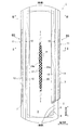
本発明に係る失禁パッド1は、図1〜図3に示されるように、ポリエチレンシートなどからなる不透液性裏面シート2と、尿などを速やかに透過させる透液性表面シート3と、これら両シート2、3間に介装された綿状パルプまたは合成パルプなどからなる吸収体4と、前記吸収体4の形状保持および拡散性向上のために、前記吸収体を囲繞するクレープ紙や不織布等からなる被包シート5と、前記吸収体4の略側縁部を起立基端とし、かつ少なくとも尿排出部位Hを含むように長手方向に所定の区間内において肌側に突出して設けられた左右一対の立体ギャザーBS、BSを形成するサイド不織布7、7とから主に構成され、かつ前記吸収体4の周囲においては、その長手方向端縁部では前記不透液性裏面シート2と透液性表面シート3との外縁部がホットメルトなどの接着剤やヒートシール等の接着手段によって接合され、またその両側縁部では吸収体4よりも側方に延出している前記不透液性裏面シート2と前記サイド不織布7とがホットメルトなどの接着剤やヒートシール等の接着手段によって接合されている。また、必要に応じて、前記透液性表面シート3と吸収体4との間に、親水性のセカンドシートを配設することができる。
[Basic configuration of incontinence pad 1]
As shown in FIGS. 1 to 3, the
以下、さらに前記失禁パッド1の構造について詳述すると、
前記不透液性裏面シート2は、ポリエチレン、ポリプロピレン等の少なくとも遮水性を有するシート材が用いられるが、この他に防水フィルムを介在して実質的に不透液性を確保した上で不織布シート(この場合には、防水フィルムと不織布とで不透液性裏面シートを構成する。)などを用いることができる。近年はムレ防止の観点から透湿性を有するものが好適に用いられる傾向にある。この遮水・透湿性シート材としては、ポリエチレンやポリプロピレン等のオレフィン系樹脂中に無機充填剤を溶融混練してシートを成形した後、一軸または二軸方向に延伸することにより得られる微多孔性シートが好適に用いられる。
Hereinafter, the structure of the
The liquid-
次いで、前記透液性表面シート3は、有孔または無孔の不織布や多孔性プラスチックシートなどが好適に用いられる。不織布を構成する素材繊維としては、たとえばポリエチレンまたはポリプロピレン等のオレフィン系、ポリエステル系、ポリアミド系等の合成繊維の他、レーヨンやキュプラ等の再生繊維、綿等の天然繊維とすることができ、スパンレース法、スパンボンド法、サーマルボンド法、メルトブローン法、ニードルパンチ法等の適宜の加工法によって得られた不織布を用いることができる。これらの加工法の内、スパンレース法は柔軟性、ドレープ性に富む点で優れ、サーマルボンド法は嵩高で圧縮復元性が高い点で優れている。
Next, as the liquid-
前記吸収体4は、たとえば綿状パルプ等の吸収性繊維と高吸水性ポリマー8とにより構成され、図示例では平面形状がパッド長手方向に長い縦長の略小判形とされている。前記高吸水性ポリマー8は例えば粒状粉とされ、吸収体4を構成するパルプ中に分散混入されている。
The
前記パルプとしては、木材から得られる化学パルプ、溶解パルプ等のセルロース繊維や、レーヨン、アセテート等の人工セルロース繊維からなるものが挙げられ、広葉樹パルプよりは繊維長の長い針葉樹パルプの方が機能および価格の面で好適に使用される。本失禁パッド1では、吸収体4を被包シート5で囲繞するため、結果的に透液性表面シート3と吸収体4との間に被包シート5が介在することになり、吸収性に優れる前記被包シート5によって尿を速やかに拡散させるとともに、これら尿等の逆戻りを防止するようになる。前記パルプの目付は、100g/m2〜600g/m2、好ましくは200g/m2〜500g/m2とするのがよい。
Examples of the pulp include chemical fibers obtained from wood, cellulose fibers such as dissolved pulp, and artificial cellulose fibers such as rayon and acetate. Softwood pulp having a longer fiber length than hardwood pulp functions and It is preferably used in terms of price. In this
前記高吸水性ポリマー8としては、たとえばポリアクリル酸塩架橋物、自己架橋したポリアクリル酸塩、アクリル酸エステル−酢酸ビニル共重合体架橋物のケン化物、イソブチレン・無水マレイン酸共重合体架橋物、ポリスルホン酸塩架橋物や、ポリエチレンオキシド、ポリアクリルアミドなどの水膨潤性ポリマーを部分架橋したもの等が挙げられる。これらの内、吸水量、吸水速度に優れるアクリル酸またはアクリル酸塩系のものが好適である。前記吸水性能を有する高吸水性ポリマーは製造プロセスにおいて、架橋密度および架橋密度勾配を調整することにより吸収倍率(吸水力)と吸収速度の調整が可能である。
Examples of the
また、前記吸収体4には合成繊維を混合しても良い。前記合成繊維は、例えばポリエチレン又はポリプロピレン等のポリオレフィン系、ポリエチレンテレフタレートやポリブチレンテレフタレート等のポリエステル系、ナイロンなどのポリアミド系、及びこれらの共重合体などを使用することができるし、これら2種を混合したものであってもよい。また、融点の高い繊維を芯とし融点の低い繊維を鞘とした芯鞘型繊維やサイドバイサイド型繊維、分割型繊維などの複合繊維も用いることができる。前記合成繊維は、尿に対する親和性を有するように、疎水性繊維の場合には親水化剤によって表面処理したものを用いるのが望ましい。
The
前記吸収体4として、前述の吸収性繊維中に高吸水性ポリマー8が分散混入されたものに代えて、それぞれ不織布などからなる上層シートと下層シートとの間に、高吸水性ポリマーが介在されたポリマーシートによって構成することも可能である。前記ポリマーシートは、前記上層シートと下層シートの外縁部において、両シートが直接ホットメルト接着剤、ヒートシール、超音波シールなどによって接合され、シート間に高吸水性ポリマーが封入されるようになっている。また、高吸水性ポリマーはホットメルト接着剤などのバインダーによって上層シート及び下層シートに結合されている。後段で詳述する吸収体凹部20の底部には、前記高吸水性ポリマーが介在しないようにしてもよいし、介在するようにしてもよい。
As the
前記吸収体4の幅寸法は、全長に亘って略等幅としてもよいし、図示例のように、股間部への当たりによって着用者にゴワ付き感を与えないように、股間部に対応する長手方向の所定区間に亘って円弧状に切り欠いた部分を設けてもよい。
The width dimension of the
前記被包シート5は、ティシュー等の紙材あるいは不織布等の透液性のシートを用いることができる。特に、資材の破壊(破れ)が生じにくい不織布を用いるのが好ましい。このような不織布としては、薄さと強度のバランスに優れたスパンボンド法やSMS法により加工された不織布、熱可塑性エラストマー樹脂などからなる弾性繊維をスパンボンド法、メルトブロー法など紡糸工程に直結してウェブを形成する方法により加工された不織布、ラテックス、ウレタン、オレフィン系の繊維など伸縮性を有する素材を主成分とする不織布が好適である。なお、被包シート5は、少なくとも吸収体4の肌当接面側(表面側)の面が撥水性でなければシートの親水度は特に問わない。
The encapsulating
本失禁パッド1の表面側両側部にはそれぞれ長手方向に沿って、かつ失禁パッド1の全長に亘ってサイド不織布7,7が設けられ、このサイド不織布7,7の外側部分が側方に延在されるとともに、前記不透液性裏面シート2が側方に延在され、これら側方に延在されたサイド不織布7部分と不透液性裏面シート2部分とをホットメルト接着剤等により接合して、前記吸収体4の両側部にそれぞれ吸収体4の存在しないサイドフラップ部が形成されている。
Side
前記サイド不織布7としては、重要視する機能の点から撥水処理不織布または親水処理不織布を使用することができる。たとえば、尿等が浸透するのを防止する、あるいは肌触り感を高めるなどの機能を重視するならば、シリコン系、パラフィン系、アルキルクロミッククロリド系撥水剤などをコーティングしたSSMSやSMS、SMMSなどの撥水処理不織布を用いるのが望ましく、尿の吸収性を重視するならば、合成繊維の製造過程で親水基を持つ化合物、例えばポリエチレングリコールの酸化生成物などを共存させて重合させる方法や、塩化第2スズのような金属塩で処理し、表面を部分溶解し多孔性とし金属の水酸化物を沈着させる方法等により合成繊維を膨潤または多孔性とし、毛細管現象を応用して親水性を与えた親水処理不織布を用いるのが望ましい。かかるサイド不織布7としては、天然繊維、合成繊維または再生繊維などを素材として、適宜の加工法によって形成されたものを使用することができる。
As the side
前記サイド不織布7、7は、適宜に折り畳まれて、前記吸収体4の略側縁近傍位置を起立基端として肌側に起立する左右一対の内側立体ギャザー10、10と、相対的に前記内側立体ギャザー10より外側に位置するとともに、前記吸収体4よりも側方に延出する前記サイドフラップ部であって、不透液性裏面シート2及びサイド不織布7によって形成された肌側に起立する左右一対の外側立体ギャザー11、11とからなる2重ギャザー構造の立体ギャザーBSを構成している。なお、前記立体ギャザーBSは、少なくとも前記サイドフラップ部に形成される外側立体ギャザー11を含んでいればよい。
The
前記内側立体ギャザー10および外側立体ギャザー11の構造についてさらに詳しく説明すると、前記サイド不織布7は、図2に示されるように、幅方向両側端をそれぞれパッド裏面側に折り返して幅方向内側及び幅方向外側にそれぞれ二重シート部分7a、7bを形成するとともに、前記幅方向内側の二重シート部分7a内部に両端または長手方向の適宜の位置が固定された1本または複数本の、図示例では1本の糸状弾性伸縮部材12が配設されるとともに、前記幅方向外側の二重シート部分7b内部に両端または長手方向の適宜の位置が固定された1本または複数本の、図示例では2本の糸状弾性伸縮部材13、13が配設され、前記幅方向内側の二重シート部分7aの基端部が吸収体4の側部に配設される透液性表面シート3の上面にホットメルト接着剤等により接着されるとともに、幅方向外側の二重シート部分7bの基端部が前記吸収体4よりも側方に延出する不透液性裏面シート2の側端部にホットメルト接着剤等により接着されることにより、前記幅方向内側の二重シート部分7aによって肌側に起立する内側立体ギャザー10が形成されるとともに、前記幅方向外側の二重シート部分7bによって肌側に起立する外側立体ギャザー11が形成されている。なお、前記サイド不織布7は、パッド長手方向の両端部では、図3に示されるように、前記糸状弾性伸縮部材12、13が配設されないとともに、前記幅方向内側の二重シート部分7aがホットメルト接着剤等によって吸収体4側に接合されている。
The structure of the inner three-dimensional gather 10 and the outer three-dimensional gather 11 will be described in more detail. As shown in FIG. 2, the side
〔吸収体凹部20について〕
前記吸収体4の肌側面(透液性表面シート3側の面)には、長手方向に沿って尿流入用の吸収体凹部20が形成されている。前記吸収体凹部20は、排出された尿を受け止めて、尿を一時貯留するとともに、前後方向への尿の拡散を誘導し、且つ吸収体4への尿の吸収速度を速め、横漏れを防止するためのものである。
[About Absorber Recess 20]
On the skin side surface of the absorbent body 4 (surface on the liquid-
前記吸収体凹部20は、吸収体4の肌側面からの圧搾により形成したものでもよいが、予め圧搾によることなく吸収体4の積繊時などに吸収体凹部20を形成したものの方が、脚圧による吸収体凹部20の変形が防止できるとともに、尿の吸収及び拡散性に優れるなどの理由から望ましい。
Although the said absorber recessed
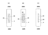
前記吸収体凹部20は、吸収体4の肌側の面に、尿排出部位Hを含む長手方向に沿って、凹溝状又はスリット状に形成した部分である。図2などに示される例では、前記吸収体凹部20は、吸収体4の肌側(透液性表面シート3側)の面において、周囲より非肌側(不透液性裏面シート2側)に凹んだ底面を有する非貫通型の凹溝状に形成されている。この吸収体凹部20は、例えば図4に示されるように、(A)積繊、又は(B)吸収体凹部20の底部の厚みで形成された下層吸収体4aと、前記吸収体凹部20に対応する部分が開口した1層又は複数層の、図示例では1層の上層吸収体4bとの積層構造などによって、圧搾によることなく形成したものが好ましい。前記吸収体凹部20としては、吸収体4の肌側面から非肌側面にかけて、吸収体4を構成するパルプやポリマーが介在しない厚み方向に貫通したスリット状に形成してもよい。
The
前記吸収体凹部20は、図1に示されるように、吸収体4の長手方向中心線上に1条のみ形成してもよいし、失禁パッド1の幅方向に離間して複数条で形成したり、パッド長手方向に離間する不連続線状に形成するなど、種々の形態で形成してもよい(図10及び図11参照)。いずれにおいても、尿排出部位Hに対応する部位を含む領域に形成されるとともに、パッド長手方向に長い線状に形成されている。
As shown in FIG. 1, the
本失禁パッド1では、前記吸収体凹部20は、図5に示されるように、長手方向の両端部がそれぞれ、端部側に向かって漸次幅を狭めた先細形状の幅漸減区間23とされ、前記幅漸減区間23はそれぞれ、吸収体凹部20の全長Lに対し20%以上の長さで形成されている(幅漸減区間23の区間長M≧0.2L)。前記幅漸減区間23は、吸収体凹部20のうち、長手方向端部に向かうに従って徐々に両側壁間が幅狭に形成された区間であり、長手方向の前端部及び後端部にそれぞれ設けられている(前端部側を前側幅漸減区間23A、後端部側を後側幅漸減区間23Bとする。)。これによって、前記幅漸減区間23においては、吸収体凹部20の断面積が長手方向端部側に向かうに従って徐々に小さくなるように形成されている。前記前側幅漸減区間23A及び後側幅漸減区間23Bがそれぞれ、吸収体凹部20の全長Lに対して20%以上の長さで形成されている。
In the
前記吸収体凹部20での尿の吸収メカニズムについて説明すると、尿排出部位Hに排出された尿は、吸収体凹部20内に流れ込み、吸収体凹部20に沿って流れる過程で吸収体凹部20の内面を通って吸収体4に吸収保持されるようになる。ここで、従来のように吸収体凹部を全長に亘って等幅に形成した場合には、長手方向の両端側にいくに従って吸収体凹部内を流れる尿量が減少し、尿の流れの勢いが減少するようになるが、本失禁パッド1では、前記吸収体凹部20の両端部に前記幅漸減区間23を所定の長さで設けてあるため、尿の流れの勢いが低下するのが抑えられ、尿を吸収体凹部20の端部側まで流すことができ、尿が吸収体4の広い範囲に拡散して吸収できるようになっている。具体的には、流れる尿量を同じとした場合、前記幅漸減区間23では、等幅に形成したものより流路の断面積が徐々に減少するので、その分だけ尿が流路の長さ方向に長い範囲まで流れるようになり、尿の流れの勢いが低下するのが抑えられるとともに、尿を吸収体4の広い範囲に拡散させることができるようになる。また、図6に示されるように、幅漸減区間23において尿の流路面積が徐々に減少するのに伴って流れる尿の水位が徐々に上昇するため、尿と吸収体凹部20の両側面との高さ方向の接触面積が増加し、毛細管現象によって尿が吸収体4に引き込まれる量が増加するので、尿が吸収体4に吸収されやすくなる。このため、吸収体凹部20の前後端部まで尿が流れやすく、吸収体4の全体に亘って尿が拡散できるようになる。
The urine absorption mechanism in the
前記吸収体凹部20は、図5及び図7(A)に示されるように、長手方向の中間点から両端にかけてそれぞれ漸次幅を狭めた先細形状に形成することができる。つまり、前側幅漸減区間23A及び後側幅漸減区間23Bを前後に直接接続することによって、長手方向の中間点を境に前側に前側幅漸減区間23Aを設けるとともに、前記前側幅漸減区間23Aの後端に連続して後側幅漸減区間23Bを設けることができる。前記長手方向の中間点は、吸収体凹部20の長手方向の任意の位置に設定することができ、図示例では中央点に設定されているが、長手方向の前側又は後側に偏倚した位置に設定することも可能である。前記幅漸減区間23の長手方向の中間点から両端にかけての外形線は、幅方向の外側又は内側に膨出する弧状の曲線でもよいし、直線でもよい。図5に示される例では、長手方向中心線の両側にそれぞれ、長手方向中央点から両端に延びる幅方向外側に膨出する弧状曲線によって両側の外形線を形成するとともに、長手方向両端において前記両側の外形線を長手方向中心線上で接続させた交点が形成された形状とすることにより、全体として略瞳形状に形成されている。また、図7(A)に示される例では、長手方向中心線の両側にそれぞれ、長手方向中央点から両端に延びる直線によって両側の外形線を形成するとともに、長手方向両端において前記両側の外形線を長手方向中心線上で接続させた交点が形成された形状とすることにより、全体として略菱形に形成されている。なお、吸収体凹部20の両端において、両側の外形線を長手方向中心線上で接続する構成に代えて、吸収体凹部20の両端に長手方向中心線に直交する直線や長手方向外方側に膨出する弧状曲線などによって形成される端面を設けるようにしてもよい。
As shown in FIG. 5 and FIG. 7 (A), the
特に、前記吸収体凹部20を前述の略瞳形状に形成したもの(図5)は、略菱形に形成したもの(図7(A))より吸収体凹部20の側壁の面積が増加するため、尿と吸収体との接触面積が増加することにより吸収量が増大する、長手方向の全体に亘って滑らかに吸収体凹部20の幅が変化するので、吸収体凹部20に沿った尿の流れがスムーズになるなどの理由から好ましい。
In particular, since the
前記吸収体凹部20は、上記のように前側幅漸減区間23A及び後側幅漸減区間23Bを前後に直接接続した構成に代えて、図7(B)に示されるように、長手方向の中間部が均等な幅で形成された等幅区間24とされ、前記等幅区間24の両端に連続してそれぞれ前記前側幅漸減区間23A及び後側幅漸減区間23Bを形成するようにしてもよい。前記等幅区間24を設けることにより、吸収体凹部20が必要以上に幅広に形成されることがなくなり、尿の流れの勢いが低下しやすい長手方向両端部で、尿の流れの勢いが維持できるようになる。前記等幅区間24においては、両側面が平行する直線で形成されている。
As shown in FIG. 7B, the
図5及び図7に示されるように、前側幅漸減区間23Aの区間長と後側幅漸減区間23Bの区間長とはほぼ同一の長さで形成してもよいし、図示しないが異なる長さで形成してもよい。異なる長さとする場合、人体の構造上、後側に流れる尿の量が前側に流れる尿の量より相対的に多くなるのに対応するため、前側幅漸減区間23Aの区間長より後側幅漸減区間23Bの区間長の方が相対的に長くなるようにするのが好ましい。
As shown in FIGS. 5 and 7, the section length of the front width gradually decreasing
前記吸収体凹部20の平面寸法は、図5に示されるように、パッド長手方向の長さLが吸収体4の全長Cに対し60〜80%(0.6C≦L≦0.8C)とするのが好ましい。なお、図10(C)に示されるように、吸収体凹部20を不連続線状に形成した場合には、各溝部分の長さの合計が吸収体4の全長の60〜80%であるのが好ましい。
As shown in FIG. 5, the planar size of the
また、吸収体凹部20の最大の幅(底面の溝幅)Pは、10〜40mmとするのがよい。なお、吸収体凹部20の幅は、深さ方向に対して開口側(上側)と底面側(下側)とがほぼ同等の幅となるように、吸収体凹部20の両側の壁面が底面に対してほぼ垂直に起立するように形成するのが好ましい。
The maximum width (groove width of the bottom surface) P of the
前記吸収体凹部20の深さは、吸収体4の厚みの50%以上、具体的には5〜20mm程度とするのがよい。前記吸収体凹部20の深さは必ずしも一定である必要はなく、長手方向或いは幅方向に変化させてもよい。例えば、長手方向に変化させるには、尿排出部位Hに対応する部分では相対的に深くし、吸収体凹部20の両端部に行くほど相対的に浅くなるようにすることができるし、これとは逆の関係で形成することもできる。また、幅方向に変化させるには、吸収体を上層側から順に、貫通溝が形成された上層、貫通溝が形成された中層、溝のない下層の3層構造で構成し(図4(B)参照。ただし同図は2層構造の場合を図示している。)、上層の溝幅を中層の溝幅より大きくすることによって、深さが幅方向中央から両側に向けて段階的に浅くなるように形成することができる。
The depth of the
また、前記幅漸減区間23の区間長Mは、前述の通り吸収体凹部20の全長Lに対して20%以上(M≧0.2L)、好ましくは20〜50%(0.2L≦M≦0.5L)、より好ましくは30〜50%(0.3L≦M≦0.5L)とするのがよい。幅漸減区間23の区間長Mが20%より小さいと、先端部を先細形状にした効果が十分に発揮できず、尿が幅漸減区間23に到達する前に尿の流れの勢いが低下してしまう場合がある。
Further, the section length M of the width gradually decreasing
一方、図7(B)に示されるように、吸収体凹部20の中間に等幅区間24を形成した場合において、前記等幅区間24の長手寸法Nは、吸収体凹部20の全長Lに対し、0〜60%の長さで形成するのがよい(0≦N≦0.6L)。前記等幅部24では排尿時の勢いだけで尿が前後方向に拡散するため、0.6Lより大きくすると、尿の流れの勢いが低下しやすくなる。
On the other hand, as shown in FIG. 7B, when the
前記吸収体4の密度は、後段で詳述するエンボス部21を施さない状態で、吸収体凹部20の底面の密度と、その周辺(吸収体凹部20以外の部分)の密度とがほぼ同等となるように形成するのが好ましい。つまり、吸収体凹部20を圧搾によることなく上述の積繊や2層構造などによって凹溝状に形成することにより、吸収体の密度をほぼ同等にするのが好ましい。これにより、吸収体4内の尿の拡散性が良好になる。
The density of the
前記吸収体凹部20の底部(不透液性裏面シート2側の部分、非肌側の部分)に介在する吸収体4部分は、パルプの目付が0g/m2〜210g/m2、好ましくは70g/m2〜190g/m2とするのがよい。この吸収体部分にも吸水性ポリマー8が所定の目付で分散混入されるようにするのが好ましいが、後段で詳述するエンボス部21を設ける場合にはこの部分にポリマーが介在しないようにすることも可能である。
The absorbent 4 portion interposed in the bottom of the absorbent recess 20 (the liquid-
前記吸収体凹部20は、吸収体4に対し、図5に示される平面視で、前後にそれぞれ所定の間隔をあけた長手方向の中間位置に設けられている。吸収体凹部20の前端20aと吸収体4の前端4cとのパッド長手方向の離間距離Aは、吸収体4の全長Cに対し、10〜25%(0.15C≦A≦0.25C)とするのが好ましく、吸収体凹部20の後端20bと吸収体4の後端4dとのパッド長手方向の離間距離Bは、吸収体4の全長Cに対し、10〜20%(0.1C≦B≦0.2C)とするのが好ましい。これによって、吸収体凹部20の前側及び後側にそれぞれ、吸収体4が適切な長さで設けられるようになり、吸収体凹部20から吸収体4に吸収された体液をより確実に吸収体4に吸収保持できるようになる。
The said absorber recessed
図1に示されるように、前記吸収体凹部20に対する尿排出部位Hの位置は、前側の幅漸減区間23の中間位置になるように配置するのが好ましい。図9に示されるように、失禁パッド1を人体に装着した状態では、前側より後側の方が上向きに湾曲する変形が緩やかなため、吸収体4が上向きに変形することによって尿が流れにくくなる影響が、前側より後側の方が小さくなり、後側には比較的尿が流れやすい構造となっている。このため、比較的流れにくい前側での尿の流れを生じやすくするため、体液排出部位Hを前側の幅漸減区間23内に設けている。
As shown in FIG. 1, it is preferable to arrange the urine discharge site H with respect to the
前記吸収体4に対する透液性表面シート3の配置の態様として、吸収体4の上層側に透液性表面シート3を積層した状態で、透液性表面シート3の非肌側に前記吸収体凹部20に対応する空間が形成されるように配置してもよいが、図1及び図2に示されるように、吸収体4の上層側に透液性表面シート3を積層した状態で、透液性表面シート3の表面側からのエンボスにより、吸収体凹部20の内部に吸収体凹部20に沿ってエンボス部21を設けることによって、透液性表面シート3が吸収体凹部20の内面に沿って配置されるようにするのが好ましい。前記透液性表面シート3を吸収体凹部20の内面に沿って配置するとともに、前記吸収体凹部20の底面に前記エンボス部21を設けることによって、装着時に脚の付け根部分の内側からの脚圧によって吸収体凹部20が潰れるのが防止でき、吸収体凹部20に沿った尿の流れが生じやすくなる。前記エンボス部21は、吸収体凹部20の全長に亘って形成してもよいが、図示例のように、幅漸減区間23の先端部においてエンボス部21を設けることが不可能な場合には一部に設けない部分があってもよい。前記エンボス部21は、吸収体凹部20の長手方向に沿う波状の第1エンボス21aと、前記第1エンボス21aが幅方向外側に突出する凸部と反対側の側縁部に、凹溝に沿って形成された第2エンボス21bとから構成するのが好ましい。これにより、幅方向両側から内側に向かう脚圧に対し、強度が高くなり、吸収体凹部20が更に潰れにくくなる。前記エンボス部21を設ける場合、吸収体凹部20の底部に介在する吸収体部分には、ポリマーを設けないようにするのが好ましい。
As an aspect of arrangement of the liquid-
本失禁パッド1では、図8に示されるように、前記吸収体凹部20の尿排出部位Hに対応する位置に、拡幅した液溜まり部25を設けることができる。前記液溜まり部25は、排尿時に尿を一時貯留しておく貯留空間であり、尿排出部位Hに対応する位置及びその近傍において吸収体凹部20の両側にほぼ均等に拡幅するように形成した部分のことである。前記液溜まり部25に一時貯留された尿は、その後吸収体凹部20に沿って前後方向に流れるようになる。前記液溜まり部25の平面形状は、矩形状(図8(A))や多角形状、菱形のいずれでもよいし、円形状(図8(B))やパッド長手方向又は幅方向に長い楕円形状のいずれでもよい。好ましくは、尿の貯留・拡散が滞りなくできるパッド長手方向に長い楕円形状がよい。
In the
ところで、前記吸収体凹部20は、種々の形態で配置することができる。前記吸収体凹部20は、図1に示されるように、尿排出部位Hに対応するパッド幅方向中央部の長手方向中心線上に1条のみ形成するのが好ましいが、図10(A)、(B)に示されるように、パッド幅方向に離間して複数条形成してもよいし、同図10(C)に示されるように、パッド長手方向に離間して不連続線状に形成してもよい。複数条形成した場合には、多くの尿が一気にドッと出たときでも尿の拡散効果をより確実に高めることができるようになる。また、不連続線状に形成した場合には、吸収体凹部20が幅方向両側から脚圧などの外力を受けたときの潰れがより確実に防止できる。パッド幅方向に離間して複数条形成する場合、同図10(A)に示す偶数条でもよいし、同図10(B)に示す奇数条でもよい。
By the way, the said absorber recessed
前記吸収体凹部20は、図11に示されるように、1又は複数の枝分かれ部20b、20cを設けてもよい。前記枝分かれ部20b、20cを設けることにより、吸収体凹部20に一時貯留された尿が吸収体凹部20に沿って吸収体4の広い範囲に拡散するようになり、吸収体4のより広い範囲で尿を吸収できるようになる。図11(A)〜(C)に示される例では、前記枝分かれ部20bとして、パッド長手方向の前側、後側のいずれか一方側又は前側及び後側のそれぞれに、吸収体凹部20の両側縁から外側に延びるとともに、パッド長手方向の端部側に傾斜する複数、図示例では左右それぞれ3本ずつ設けられている。また、図11(D)〜(F)に示される例では、前記枝分かれ部20cとして、パッド長手方向の前端、後端のいずれか一方端又は前端及び後端のそれぞれに、吸収体凹部20が放射状に複数に、図示例では5本に枝分かれしたものが設けられている。
As shown in FIG. 11, the
1…失禁パッド、2…不透液性裏面シート、3…透液性表面シート、4…吸収体、5…被包シート、7…サイド不織布、8…高吸水性ポリマー、10…内側立体ギャザー、11…外側立体ギャザー、12・13…糸状弾性伸縮部材、20…吸収凹部、21…エンボス部、23…幅漸減区間、24…等幅区間、25…液溜まり部
DESCRIPTION OF
Claims (9)
前記吸収体は、前記透液性表面シート側の面の尿排出部位を含む範囲に、吸収性物品の長手方向に沿って凹溝状又はスリット状の吸収体凹部が備えられ、
前記吸収体凹部は、長手方向の両端部がそれぞれ、端部側に向かって漸次幅を狭めた先細形状の幅漸減区間とされ、前記幅漸減区間はそれぞれ、前記吸収体凹部の全長に対し20%以上の長さで形成され、
前記吸収体凹部に対する尿排出部位の位置が、前側の幅漸減区間の中間位置になるように配置されるか又は前記幅漸減区間は前側の幅漸減区間より後側の幅漸減区間の方が相対的に長く形成されていることを特徴とする吸収性物品。 In the absorbent article in which an absorbent body is interposed between the liquid-permeable top sheet and the back sheet,
The absorbent body is provided with a concave groove-shaped or slit-shaped absorbent concave portion along the longitudinal direction of the absorbent article in a range including the urine discharge site on the surface of the liquid-permeable surface sheet.
Each of the absorber recesses is a tapered width gradually decreasing section in which both end portions in the longitudinal direction are gradually narrowed toward the end side, and each of the width gradually decreasing sections is 20 with respect to the total length of the absorber recess. % Or more in length ,
The position of the urine discharge site with respect to the concave portion of the absorber is arranged so as to be an intermediate position of the front width gradually decreasing section, or the width gradually decreasing section is more relative to the rear width gradually decreasing section than the front width gradually decreasing section. Absorbent article characterized in that it is formed long .
Priority Applications (7)
| Application Number | Priority Date | Filing Date | Title |
|---|---|---|---|
| JP2015151811A JP6138872B2 (en) | 2015-07-31 | 2015-07-31 | Absorbent articles |
| CN201680031391.0A CN107613933A (en) | 2015-07-31 | 2016-07-22 | Absorbent commodity |
| PCT/JP2016/071633 WO2017022532A1 (en) | 2015-07-31 | 2016-07-22 | Absorbent article |
| US15/742,178 US10806637B2 (en) | 2015-07-31 | 2016-07-22 | Absorbent article |
| EP16832811.0A EP3329889B1 (en) | 2015-07-31 | 2016-07-22 | Absorbent article |
| KR1020187004180A KR101881269B1 (en) | 2015-07-31 | 2016-07-22 | Absorbent article |
| TW105124114A TWI708594B (en) | 2015-07-31 | 2016-07-29 | Absorbent article |
Applications Claiming Priority (1)
| Application Number | Priority Date | Filing Date | Title |
|---|---|---|---|
| JP2015151811A JP6138872B2 (en) | 2015-07-31 | 2015-07-31 | Absorbent articles |
Publications (3)
| Publication Number | Publication Date |
|---|---|
| JP2017029352A JP2017029352A (en) | 2017-02-09 |
| JP2017029352A5 JP2017029352A5 (en) | 2017-04-20 |
| JP6138872B2 true JP6138872B2 (en) | 2017-05-31 |
Family
ID=57942929
Family Applications (1)
| Application Number | Title | Priority Date | Filing Date |
|---|---|---|---|
| JP2015151811A Active JP6138872B2 (en) | 2015-07-31 | 2015-07-31 | Absorbent articles |
Country Status (7)
| Country | Link |
|---|---|
| US (1) | US10806637B2 (en) |
| EP (1) | EP3329889B1 (en) |
| JP (1) | JP6138872B2 (en) |
| KR (1) | KR101881269B1 (en) |
| CN (1) | CN107613933A (en) |
| TW (1) | TWI708594B (en) |
| WO (1) | WO2017022532A1 (en) |
Families Citing this family (8)
| Publication number | Priority date | Publication date | Assignee | Title |
|---|---|---|---|---|
| JP5938440B2 (en) * | 2014-06-13 | 2016-06-22 | 大王製紙株式会社 | Absorbent articles |
| JP2017086578A (en) * | 2015-11-12 | 2017-05-25 | 日本製紙クレシア株式会社 | Absorbent article |
| JP6641559B2 (en) * | 2015-11-27 | 2020-02-05 | 日本製紙クレシア株式会社 | Absorbent articles |
| WO2018230013A1 (en) * | 2017-06-14 | 2018-12-20 | 王子ホールディングス株式会社 | Absorber complex |
| JP7019889B2 (en) * | 2017-10-31 | 2022-02-16 | 日本製紙クレシア株式会社 | Absorbent article for loose stool |
| EP3536294B1 (en) * | 2018-03-09 | 2021-01-27 | Drylock Technologies NV | Absorbent article with channels |
| JP7194585B2 (en) * | 2018-12-26 | 2022-12-22 | 大王製紙株式会社 | absorbent article |
| JP7318373B2 (en) * | 2019-07-02 | 2023-08-01 | 王子ホールディングス株式会社 | absorbent article |
Family Cites Families (25)
| Publication number | Priority date | Publication date | Assignee | Title |
|---|---|---|---|---|
| US2964039A (en) * | 1955-01-18 | 1960-12-13 | Personal Products Corp | Preformed, arcuate sanitary napkins |
| US3736931A (en) * | 1971-06-09 | 1973-06-05 | J Glassman | Catamenial napkin |
| JPS515884A (en) | 1974-07-03 | 1976-01-19 | Hitachi Ltd | Hakunetsudenkyuno seidentososochi |
| GB2030529B (en) | 1978-09-25 | 1982-12-15 | Eaton Gmbh | Circuit controlling the energisation of power steering in a battery powered vehicle |
| JPS6017342B2 (en) | 1978-12-11 | 1985-05-02 | 昭和電工株式会社 | Surface treatment method for propylene polymer molded articles |
| US5062840B1 (en) * | 1989-05-22 | 1995-01-03 | John N Holt | Disposable diapers |
| SE504147C2 (en) * | 1994-10-19 | 1996-11-25 | Marlene Sandberg | Diaper or similar hygiene product, comprising an absorbent body having a recess, consisting of a central portion and projecting channels extending in different directions from it |
| US6011195A (en) * | 1996-10-10 | 2000-01-04 | Kimberly-Clark Worldwide, Inc. | Wet resilient absorbent article |
| JP3823504B2 (en) * | 1997-12-24 | 2006-09-20 | チッソ株式会社 | Liquid diffusive sheet and absorbent article using the same |
| JP3639447B2 (en) * | 1998-12-11 | 2005-04-20 | ユニ・チャーム株式会社 | Disposable body fluid absorbent article |
| US7067711B2 (en) * | 2002-12-05 | 2006-06-27 | Uni-Charm Corporation | Elongated absorbent article |
| JP4889451B2 (en) * | 2006-11-09 | 2012-03-07 | 花王株式会社 | Absorbent articles |
| EP2087866A4 (en) * | 2006-11-22 | 2011-12-28 | Uni Charm Corp | Absorptive article and method of producing the same |
| JP5105884B2 (en) * | 2007-01-17 | 2012-12-26 | 花王株式会社 | Absorbent articles |
| JP5001097B2 (en) * | 2007-09-03 | 2012-08-15 | 花王株式会社 | Sanitary napkin |
| JP5544100B2 (en) | 2009-02-27 | 2014-07-09 | 大王製紙株式会社 | Absorbent articles |
| JP5349283B2 (en) | 2009-12-25 | 2013-11-20 | 大王製紙株式会社 | Absorbent articles |
| JP5578025B2 (en) | 2010-10-27 | 2014-08-27 | 王子ホールディングス株式会社 | Absorbent articles |
| CN201939599U (en) * | 2011-01-19 | 2011-08-24 | 福建中天生活用品有限公司 | Improved sanitary napkin |
| US9017304B1 (en) * | 2011-01-26 | 2015-04-28 | Joyce Betts | Feminine sanitary napkin |
| CN103596535B (en) * | 2011-06-10 | 2015-11-25 | 宝洁公司 | For the absorbent cores of disposable absorbent article |
| AU2011372072B2 (en) * | 2011-06-28 | 2016-04-21 | Essity Hygiene And Health Aktiebolag | Absorbent article having intake structure |
| JP6081825B2 (en) * | 2013-03-07 | 2017-02-15 | 大王製紙株式会社 | Absorbent articles |
| JP6031428B2 (en) * | 2013-11-05 | 2016-11-24 | 大王製紙株式会社 | Absorbent articles |
| JP6033765B2 (en) * | 2013-12-26 | 2016-11-30 | 大王製紙株式会社 | Method for manufacturing absorbent article |
-
2015
- 2015-07-31 JP JP2015151811A patent/JP6138872B2/en active Active
-
2016
- 2016-07-22 KR KR1020187004180A patent/KR101881269B1/en active IP Right Grant
- 2016-07-22 CN CN201680031391.0A patent/CN107613933A/en active Pending
- 2016-07-22 WO PCT/JP2016/071633 patent/WO2017022532A1/en active Application Filing
- 2016-07-22 EP EP16832811.0A patent/EP3329889B1/en active Active
- 2016-07-22 US US15/742,178 patent/US10806637B2/en active Active
- 2016-07-29 TW TW105124114A patent/TWI708594B/en active
Also Published As
| Publication number | Publication date |
|---|---|
| US20180193204A1 (en) | 2018-07-12 |
| EP3329889A4 (en) | 2018-06-06 |
| TWI708594B (en) | 2020-11-01 |
| EP3329889A1 (en) | 2018-06-06 |
| CN107613933A (en) | 2018-01-19 |
| EP3329889B1 (en) | 2021-04-21 |
| WO2017022532A1 (en) | 2017-02-09 |
| KR101881269B1 (en) | 2018-07-23 |
| TW201707665A (en) | 2017-03-01 |
| KR20180021203A (en) | 2018-02-28 |
| US10806637B2 (en) | 2020-10-20 |
| JP2017029352A (en) | 2017-02-09 |
Similar Documents
| Publication | Publication Date | Title |
|---|---|---|
| JP6138872B2 (en) | Absorbent articles | |
| JP6031428B2 (en) | Absorbent articles | |
| JP5992381B2 (en) | Absorbent articles | |
| WO2016031668A1 (en) | Absorbent article | |
| JP2017029352A5 (en) | ||
| JP2015089382A5 (en) | ||
| JP5938440B2 (en) | Absorbent articles | |
| JP6047606B2 (en) | Absorbent articles | |
| JP6581337B2 (en) | Absorbent articles | |
| JP2015047432A5 (en) | ||
| JP6081422B2 (en) | Absorbent articles | |
| JP6484416B2 (en) | Absorbent articles | |
| JP6371814B2 (en) | Absorbent articles | |
| JP2018050987A5 (en) | ||
| JP2016049247A (en) | Absorbent article | |
| JP6329789B2 (en) | Absorbent articles | |
| JP6441621B2 (en) | Absorbent articles | |
| JP6484417B2 (en) | Absorbent articles | |
| JP5897762B2 (en) | Absorbent articles | |
| JP5938438B2 (en) | Absorbent articles | |
| JP6457780B2 (en) | Absorbent articles | |
| JP5944953B2 (en) | Absorbent articles | |
| JP5957329B2 (en) | Absorbent articles | |
| JP6457764B2 (en) | Absorbent articles | |
| JP2018143431A (en) | Men's absorbent article |
Legal Events
| Date | Code | Title | Description |
|---|---|---|---|
| A521 | Request for written amendment filed |
Free format text: JAPANESE INTERMEDIATE CODE: A523 Effective date: 20170309 |
|
| A621 | Written request for application examination |
Free format text: JAPANESE INTERMEDIATE CODE: A621 Effective date: 20170309 |
|
| A871 | Explanation of circumstances concerning accelerated examination |
Free format text: JAPANESE INTERMEDIATE CODE: A871 Effective date: 20170309 |
|
| A975 | Report on accelerated examination |
Free format text: JAPANESE INTERMEDIATE CODE: A971005 Effective date: 20170317 |
|
| TRDD | Decision of grant or rejection written | ||
| A01 | Written decision to grant a patent or to grant a registration (utility model) |
Free format text: JAPANESE INTERMEDIATE CODE: A01 Effective date: 20170405 |
|
| A61 | First payment of annual fees (during grant procedure) |
Free format text: JAPANESE INTERMEDIATE CODE: A61 Effective date: 20170426 |
|
| R150 | Certificate of patent or registration of utility model |
Ref document number: 6138872 Country of ref document: JP Free format text: JAPANESE INTERMEDIATE CODE: R150 |
|
| R250 | Receipt of annual fees |
Free format text: JAPANESE INTERMEDIATE CODE: R250 |
|
| R250 | Receipt of annual fees |
Free format text: JAPANESE INTERMEDIATE CODE: R250 |
|
| R250 | Receipt of annual fees |
Free format text: JAPANESE INTERMEDIATE CODE: R250 |