JP6137125B2 - Manufacturing method of fuel cell case - Google Patents
Manufacturing method of fuel cell case Download PDFInfo
- Publication number
- JP6137125B2 JP6137125B2 JP2014230492A JP2014230492A JP6137125B2 JP 6137125 B2 JP6137125 B2 JP 6137125B2 JP 2014230492 A JP2014230492 A JP 2014230492A JP 2014230492 A JP2014230492 A JP 2014230492A JP 6137125 B2 JP6137125 B2 JP 6137125B2
- Authority
- JP
- Japan
- Prior art keywords
- fuel cell
- vehicle
- cell case
- case
- hole
- Prior art date
- Legal status (The legal status is an assumption and is not a legal conclusion. Google has not performed a legal analysis and makes no representation as to the accuracy of the status listed.)
- Active
Links
Images


Classifications
-
- H—ELECTRICITY
- H01—ELECTRIC ELEMENTS
- H01M—PROCESSES OR MEANS, e.g. BATTERIES, FOR THE DIRECT CONVERSION OF CHEMICAL ENERGY INTO ELECTRICAL ENERGY
- H01M50/00—Constructional details or processes of manufacture of the non-active parts of electrochemical cells other than fuel cells, e.g. hybrid cells
- H01M50/20—Mountings; Secondary casings or frames; Racks, modules or packs; Suspension devices; Shock absorbers; Transport or carrying devices; Holders
-
- H—ELECTRICITY
- H01—ELECTRIC ELEMENTS
- H01M—PROCESSES OR MEANS, e.g. BATTERIES, FOR THE DIRECT CONVERSION OF CHEMICAL ENERGY INTO ELECTRICAL ENERGY
- H01M8/00—Fuel cells; Manufacture thereof
- H01M8/24—Grouping of fuel cells, e.g. stacking of fuel cells
- H01M8/2465—Details of groupings of fuel cells
- H01M8/247—Arrangements for tightening a stack, for accommodation of a stack in a tank or for assembling different tanks
- H01M8/2475—Enclosures, casings or containers of fuel cell stacks
-
- H—ELECTRICITY
- H01—ELECTRIC ELEMENTS
- H01M—PROCESSES OR MEANS, e.g. BATTERIES, FOR THE DIRECT CONVERSION OF CHEMICAL ENERGY INTO ELECTRICAL ENERGY
- H01M50/00—Constructional details or processes of manufacture of the non-active parts of electrochemical cells other than fuel cells, e.g. hybrid cells
- H01M50/10—Primary casings; Jackets or wrappings
- H01M50/116—Primary casings; Jackets or wrappings characterised by the material
-
- H—ELECTRICITY
- H01—ELECTRIC ELEMENTS
- H01M—PROCESSES OR MEANS, e.g. BATTERIES, FOR THE DIRECT CONVERSION OF CHEMICAL ENERGY INTO ELECTRICAL ENERGY
- H01M2250/00—Fuel cells for particular applications; Specific features of fuel cell system
- H01M2250/20—Fuel cells in motive systems, e.g. vehicle, ship, plane
-
- Y—GENERAL TAGGING OF NEW TECHNOLOGICAL DEVELOPMENTS; GENERAL TAGGING OF CROSS-SECTIONAL TECHNOLOGIES SPANNING OVER SEVERAL SECTIONS OF THE IPC; TECHNICAL SUBJECTS COVERED BY FORMER USPC CROSS-REFERENCE ART COLLECTIONS [XRACs] AND DIGESTS
- Y02—TECHNOLOGIES OR APPLICATIONS FOR MITIGATION OR ADAPTATION AGAINST CLIMATE CHANGE
- Y02E—REDUCTION OF GREENHOUSE GAS [GHG] EMISSIONS, RELATED TO ENERGY GENERATION, TRANSMISSION OR DISTRIBUTION
- Y02E60/00—Enabling technologies; Technologies with a potential or indirect contribution to GHG emissions mitigation
- Y02E60/10—Energy storage using batteries
-
- Y—GENERAL TAGGING OF NEW TECHNOLOGICAL DEVELOPMENTS; GENERAL TAGGING OF CROSS-SECTIONAL TECHNOLOGIES SPANNING OVER SEVERAL SECTIONS OF THE IPC; TECHNICAL SUBJECTS COVERED BY FORMER USPC CROSS-REFERENCE ART COLLECTIONS [XRACs] AND DIGESTS
- Y02—TECHNOLOGIES OR APPLICATIONS FOR MITIGATION OR ADAPTATION AGAINST CLIMATE CHANGE
- Y02E—REDUCTION OF GREENHOUSE GAS [GHG] EMISSIONS, RELATED TO ENERGY GENERATION, TRANSMISSION OR DISTRIBUTION
- Y02E60/00—Enabling technologies; Technologies with a potential or indirect contribution to GHG emissions mitigation
- Y02E60/30—Hydrogen technology
- Y02E60/50—Fuel cells
-
- Y—GENERAL TAGGING OF NEW TECHNOLOGICAL DEVELOPMENTS; GENERAL TAGGING OF CROSS-SECTIONAL TECHNOLOGIES SPANNING OVER SEVERAL SECTIONS OF THE IPC; TECHNICAL SUBJECTS COVERED BY FORMER USPC CROSS-REFERENCE ART COLLECTIONS [XRACs] AND DIGESTS
- Y02—TECHNOLOGIES OR APPLICATIONS FOR MITIGATION OR ADAPTATION AGAINST CLIMATE CHANGE
- Y02P—CLIMATE CHANGE MITIGATION TECHNOLOGIES IN THE PRODUCTION OR PROCESSING OF GOODS
- Y02P70/00—Climate change mitigation technologies in the production process for final industrial or consumer products
- Y02P70/50—Manufacturing or production processes characterised by the final manufactured product
-
- Y—GENERAL TAGGING OF NEW TECHNOLOGICAL DEVELOPMENTS; GENERAL TAGGING OF CROSS-SECTIONAL TECHNOLOGIES SPANNING OVER SEVERAL SECTIONS OF THE IPC; TECHNICAL SUBJECTS COVERED BY FORMER USPC CROSS-REFERENCE ART COLLECTIONS [XRACs] AND DIGESTS
- Y02—TECHNOLOGIES OR APPLICATIONS FOR MITIGATION OR ADAPTATION AGAINST CLIMATE CHANGE
- Y02T—CLIMATE CHANGE MITIGATION TECHNOLOGIES RELATED TO TRANSPORTATION
- Y02T90/00—Enabling technologies or technologies with a potential or indirect contribution to GHG emissions mitigation
- Y02T90/40—Application of hydrogen technology to transportation, e.g. using fuel cells
Landscapes
- Chemical & Material Sciences (AREA)
- Chemical Kinetics & Catalysis (AREA)
- Electrochemistry (AREA)
- General Chemical & Material Sciences (AREA)
- Life Sciences & Earth Sciences (AREA)
- Engineering & Computer Science (AREA)
- Manufacturing & Machinery (AREA)
- Sustainable Development (AREA)
- Sustainable Energy (AREA)
- Fuel Cell (AREA)
- Electric Propulsion And Braking For Vehicles (AREA)
- Arrangement Or Mounting Of Propulsion Units For Vehicles (AREA)
Description
本発明は、燃料電池ケースの製造方法に関する。 The present invention relates to a method for manufacturing a fuel cell case.
燃料電池を搭載する車両として、燃料電池を燃料電池ケースに収容した燃料電池モジュールを車両の床下に配置したものが提案されている(特許文献1を参照)。 As a vehicle on which a fuel cell is mounted, a fuel cell module in which a fuel cell is accommodated in a fuel cell case is arranged under the floor of the vehicle (see Patent Document 1).
車両の床下に搭載される燃料電池モジュールにアルミニウム系の燃料電池ケースを採用する場合、錆の発生を防止するために陽極酸化処理によって燃料電池ケースの表面にアルマイトを形成することが考えられる。しかしながら、陽極酸化処理において接点となる表面にはアルマイトが形成されないことから、特許文献1の燃料電池ケースでは、陽極酸化処理において接点に用いる部位を別途形成する必要があるため、製造コストが増大するという課題があった。そのため、アルミニウム系の燃料電池ケースにおいて陽極酸化処理のための製造コストを抑制可能な技術が望まれていた。 When an aluminum-based fuel cell case is employed for a fuel cell module mounted under the floor of a vehicle, anodization may be formed on the surface of the fuel cell case by anodizing to prevent rusting. However, since alumite is not formed on the surface that becomes the contact in the anodizing process, the fuel cell case of Patent Document 1 requires a separate part to be used for the contact in the anodizing process, which increases the manufacturing cost. There was a problem. Therefore, there has been a demand for a technique capable of suppressing the manufacturing cost for anodizing treatment in an aluminum fuel cell case.
本発明は、上述の課題の少なくとも一部を解決するためになされたものであり、以下の形態として実現することが可能である。 SUMMARY An advantage of some aspects of the invention is to solve at least a part of the problems described above, and the invention can be implemented as the following forms.
(1)本発明の一形態によれば、アルミニウムまたはアルミニウム合金から成り、燃料電池を収納する燃料電池ケースを製造する、燃料電池ケースの製造方法が提供される。この製造方法は、前記燃料電池ケースを車両に搭載する際に前記燃料電池ケースを位置決めするピンに挿入される貫通孔を、前記燃料電池ケースに形成し;前記貫通孔の表面を接点に用いる陽極酸化処理によって、前記燃料電池ケースの表面にアルマイトを形成する。この形態によれば、車両の搭載時に使用される貫通孔の表面を陽極酸化処理の接点に流用するため、陽極酸化処理の接点に用いる部位を別途形成する場合と比較して製造コストを抑制できる。 (1) According to one form of this invention, the manufacturing method of a fuel cell case which consists of aluminum or aluminum alloy and manufactures the fuel cell case which accommodates a fuel cell is provided. In this manufacturing method, when the fuel cell case is mounted on a vehicle, a through hole inserted into a pin for positioning the fuel cell case is formed in the fuel cell case; the anode using the surface of the through hole as a contact Alumite is formed on the surface of the fuel cell case by oxidation treatment. According to this aspect, since the surface of the through-hole used when the vehicle is mounted is diverted to the anodizing contact, the manufacturing cost can be suppressed as compared with the case where a part used for the anodizing contact is separately formed. .
(2)上記形態における燃料電池ケースの製造方法において、前記貫通孔を切削加工によって形成してもよい。この形態によれば、陽極酸化処理の接点として十分な平面度を有する表面を形成できる。 (2) In the manufacturing method of the fuel cell case in the above embodiment, the through hole may be formed by cutting. According to this embodiment, a surface having sufficient flatness as a contact for anodization can be formed.
(3)上記形態における燃料電池ケースの製造方法において、前記車両に搭載された状態で、車両前後方向における前記燃料電池ケースの長さは、前車両左右方向における前記燃料電池ケースの長さより短く、前記燃料電池ケースの部位のうち、前記車両に搭載された際に前記燃料電池より車両前方に位置する第1の部位と、前記車両に搭載された際に前記燃料電池より車両後方に位置する第2の部位とに、前記貫通孔をそれぞれ形成してもよい。この形態によれば、車両左右方向に貫通孔をそれぞれ形成した場合と比較して、貫通孔およびピンの位置ずれによる影響が軽減されるため、ピンを貫通孔に挿入しやすくなる。 (3) In the fuel cell case manufacturing method according to the above aspect, the length of the fuel cell case in the vehicle longitudinal direction is shorter than the length of the fuel cell case in the vehicle left-right direction when mounted on the vehicle. Of the parts of the fuel cell case, a first part located on the front side of the vehicle when mounted on the vehicle and a first part located on the rear side of the fuel cell when mounted on the vehicle. You may form the said through-hole in 2 site | parts, respectively. According to this embodiment, compared to the case where the through holes are formed in the left and right direction of the vehicle, the influence of the positional displacement of the through holes and the pins is reduced, so that the pins can be easily inserted into the through holes.
(4)上記形態における燃料電池ケースの製造方法において、前記燃料電池ケースの部位のうち、前記車両に搭載する際に車両左右方向の一方から目視可能な複数の部位に、前記貫通孔をそれぞれ形成してもよい。この形態によれば、車両左右方向の一方から目視しながらピンを各貫通孔に挿入できる。 (4) In the method of manufacturing a fuel cell case according to the above aspect, the through holes are formed in a plurality of portions that are visible from one side in the vehicle left-right direction when mounted on the vehicle among the portions of the fuel cell case. May be. According to this aspect, the pins can be inserted into the respective through holes while being visually observed from one side in the vehicle left-right direction.
本発明は、燃料電池ケースの製造方法以外の種々の形態で実現することも可能である。例えば、本願発明は、燃料電池ケース、燃料電池モジュール、車両、並びに、これらを製造する装置などの形態で実現することができる。 The present invention can also be realized in various forms other than the manufacturing method of the fuel cell case. For example, the present invention can be realized in the form of a fuel cell case, a fuel cell module, a vehicle, and an apparatus for manufacturing these.
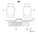
図1は、車両10の概略構成を示す説明図である。図2は、車両10の断面形状を示す断面図である。図2には、図1の矢視F2−F2から見た車両10の断面が示されている。図1には、相互に直交するXYZ軸が図示されている。図1のXYZ軸におけるX軸は、車両10を後方から見た場合に車両10の左側から車両10の右側に向かう座標軸である。図1のXYZ軸におけるY軸は、車両10の前方から後方に向かう座標軸である。図1のXYZ軸におけるZ軸は、重力方向の下方から上方に向かう座標軸である。図1のXYZ軸は、他の図におけるXYZ軸に対応する。
FIG. 1 is an explanatory diagram showing a schematic configuration of the
車両10は、車体12と、燃料電池モジュール200とを備える。車両10は、燃料電池モジュール200で生成した電力を用いて走行する。車両10の車体12は、車両10の外殻を構成する。車体12には、座席20,22,24、並びに、車輪32,34,36,38が設けられている。
The
座席20,22,24は、乗客が着席可能に構成されている。座席20は、車体12の右側(+X軸方向側)に位置する。座席22は、車体12の左側(−X軸方向側)に位置する。座席24は、座席20および座席22より後方(+Y軸方向側)に位置する。
The
車輪32,34,36,38は、燃料電池モジュール200で生成された電力を用いて駆動される。他の実施形態では、車両10の駆動輪は、前方に位置する車輪32,34のみであってもよいし、後方に位置する車輪36,38のみであってもよい。
The
車両10の車体12は、薄板を成型した床部44を備える。床部44の重力方向下側(−Z軸方向側)には、燃料電池モジュール200が設けられている。床部44には、突出部46が形成されている。突出部46は、床部44の部位のうち、重力方向上側(+Z軸方向側)に突出するとともに車両10の前方から後方へと延びた部位である。
The
車両10の燃料電池モジュール200は、燃料電池スタック210を収納した装置である。燃料電池スタック210は、反応ガスの電気化学反応によって発電する複数のセルを積層したスタック構造を有する。本実施形態では、燃料電池スタック210は、水素ガスおよび空気の供給を受けて、水素と酸素との電気化学反応によって発電する。
The
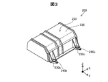
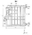
図3は、燃料電池モジュール200の外観構成を示す説明図である。図4は、燃料電池モジュール200の平面図である。図4には、+Z軸方向から見た燃料電池モジュール200が示されている。
FIG. 3 is an explanatory diagram showing an external configuration of the
燃料電池モジュール200は、燃料電池ケース220を備える。燃料電池モジュール200の燃料電池ケース220は、燃料電池スタック210を収納する。本実施形態では、燃料電池ケース220は、アルミニウム合金から成る。他の実施形態では、燃料電池ケース220は、アルミニウムから成ってもよい。燃料電池ケース220は、ケース本体部225と、マウント部230a,230b,230cと、位置決め部240a,240b,240cとを備える。
The
燃料電池ケース220のケース本体部225は、−Z軸方向に開口部を有する箱状を成す部位である。ケース本体部225の内側には、燃料電池スタック210が収容される。本実施形態では、ケース本体部225の開口部は、燃料電池スタック210を収容した後にカバーによって閉じられる。本実施形態では、車両10に搭載された状態で、車両10の前後方向(Y軸方向)におけるケース本体部225の長さLyは、車両10の左右方向(X軸方向)におけるケース本体部225の長さLxより短い。
The case
燃料電池ケース220のマウント部230a,230b,230cは、それぞれ貫通孔を有する。これらの貫通孔には、燃料電池モジュール200を車体12に連結するマウント部材(図示しない)がそれぞれ圧入される。
The
マウント部230a,230b,230cは、ケース本体部225の外縁に設けられている。本実施形態では、マウント部230aは、ケース本体部225の−Y軸方向側の外縁における中央寄りに設けられている。本実施形態では、マウント部230bは、ケース本体部225における+Y軸方向側の外縁のうち−X軸方向寄りに設けられている。本実施形態では、マウント部230cは、ケース本体部225における+Y軸方向側の外縁のうち+X軸方向寄りに設けられている。
The
燃料電池ケース220の位置決め部240a,240b,240cは、燃料電池ケース220が車両10に搭載される際に車両10に対する位置の基準となる。位置決め部240a,240b,240cは、ケース本体部225の外縁に設けられている。本実施形態では、位置決め部240aは、ケース本体部225の外縁のうちマウント部230aの近傍に設けられている。本実施形態では、位置決め部240bは、ケース本体部225の外縁のうちマウント部230bの近傍に設けられている。本実施形態では、位置決め部240cは、ケース本体部225の外縁のうちマウント部230cの近傍に設けられている。
The positioning
位置決め部240aには、貫通孔248aが形成されている。位置決め部240bには、貫通孔248bが形成されている。位置決め部240cには、貫通孔248cが形成されている。貫通孔248a,248b,248cには、燃料電池ケース220を車両10に対して位置決めするピンが挿入される。本実施形態では、貫通孔248a,248b,248cは、切削加工によって形成される。本実施形態では、貫通孔248a,248b,248cは、Z軸方向に貫通した孔である。本実施形態の説明では、3つの位置決め部の各々を総称する場合には符号「240」を使用する。本実施形態の説明では、3つの貫通孔の各々を総称する場合には符号「248」を使用する。
A through
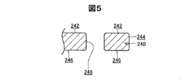
図5は、位置決め部240の断面図である。図5には、位置決め部240をZ軸に沿った面で切断した断面が示されている。
FIG. 5 is a cross-sectional view of the
位置決め部240は、貫通孔248の他、面242と、面244と、面246とを有する。位置決め部240の面242は、+Z軸方向を向いた燃料電池ケース220の表面である。位置決め部240の面244は、Z軸に沿った燃料電池ケース220の表面であり、燃料電池ケース220の外縁を構成する。位置決め部240の面246は、−Z軸方向を向いた燃料電池ケース220の表面である。
The
燃料電池ケース220の表面のうち、貫通孔248の表面には、アルマイトが形成されていない。本実施形態では、燃料電池ケース220の表面にアルマイトを形成する際、貫通孔248の表面が陽極酸化処理における接点として利用されるため、貫通孔248の表面には、アルマイトが形成されていない。本実施形態では、貫通孔248の表面を除く燃料電池ケース220の表面のうち、面242,244,246を含む燃料電池ケース220の表面にアルマイトが形成されている。他の実施形態では、貫通孔248の表面を除く燃料電池ケース220の表面の少なくとも一部は、陽極酸化処理に際しマスキングによってアルマイトが形成されていない表面であってもよい。本実施形態では、3つの貫通孔248a,248b,248cの全てにアルマイトが形成されていない。他の実施形態では、複数の貫通孔248のうち少なくとも1つの貫通孔248の表面が、陽極酸化処理における接点として利用され、アルマイトが形成されていない表面であってもよい。
Of the surface of the
本実施形態では、貫通孔248aは、燃料電池ケース220の部位のうち車両10に搭載された際に燃料電池スタック210より車両前方(−Y軸方向側)に位置する部位に設けられている。本実施形態では、貫通孔248bは、燃料電池ケース220の部位のうち車両10に搭載された際に燃料電池スタック210より車両後方(+Y軸方向側)に位置する部位に設けられている。本実施形態では、貫通孔248cは、燃料電池ケース220の部位のうち車両10に搭載された際に燃料電池スタック210より車両後方(+Y軸方向側)に位置する部位に設けられている。
In the present embodiment, the through
本実施形態では、3つの貫通孔248a,248b,248cは、車両10に搭載する際に車両左方向の一方である車両左方向(−X軸方向)から目視可能な部位に設けられている。他の実施形態では、3つの貫通孔248a,248b,248cは、車両10に搭載する際に車両左方向の他方である車両右方向(+X軸方向)から目視可能な部位に設けられていてもよい。車両10に搭載する際に車両左方向の一方から目視可能な部位に設けられる貫通孔248は、3つに限らず、2つ以上であればよい。本実施形態では、位置決め部240は、マウント部230a,230b,230cの近傍に位置する。これによって、位置決め部240に対する位置決めがしやすいとともに、マウント部230a,230b,230cが確実に陽極酸化処理されるためマウント部230a,230b,230cの防錆に有利である。他の実施形態では、位置決め部240は、マウント部230a,230b,230cの近傍とは異なる部位に位置してもよい。
In the present embodiment, the three through
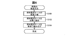
図6は、車両10の製造方法を示す工程図である。車両10を製造する際には、製造者は、燃料電池ケース220を製造する(ステップS100)。
FIG. 6 is a process diagram showing a method for manufacturing the
燃料電池ケース220を製造した後(ステップS100)、製造者は、燃料電池モジュール200に組み込まれた燃料電池ケース220を治具に固定する(ステップS102)。製造者は、燃料電池ケース220の貫通孔248を、治具に設けられたピンに嵌めることによって、燃料電池ケース220を治具に固定する。
After manufacturing the fuel cell case 220 (step S100), the manufacturer fixes the
燃料電池ケース220を治具に固定した後(ステップS102)、製造者は、治具によって車体12に対して燃料電池ケース220を位置決めした上で、燃料電池ケース220を車体12に組み付ける(ステップS104)。これらの工程を経て、燃料電池モジュール200を搭載した車両10が完成する。
After fixing the
図7は、燃料電池ケース220を製造する製造工程(ステップS100)の詳細を示す工程図である。燃料電池ケース220を製造する際には、製造者は、鋳造によって燃料電池ケース220を成形する(ステップS200)。本実施形態では、製造者は、アルミニウム合金を用いて燃料電池ケース220を鋳造する。
FIG. 7 is a process diagram showing details of the manufacturing process (step S100) for manufacturing the
燃料電池ケース220を鋳造した後(ステップS200)、製造者は、貫通孔248を燃料電池ケース220に形成する(ステップS202)。本実施形態では、製造者は、3つの貫通孔248a,248b,248cを形成する。本実施形態では、製造者は、切削加工によって貫通孔248を燃料電池ケース220に形成する。
After casting the fuel cell case 220 (step S200), the manufacturer forms the through
燃料電池ケース220に貫通孔248を形成した後(ステップS202)、製造者は、貫通孔248の表面を接点に用いる陽極酸化処理によって、燃料電池ケース220の表面にアルマイトを形成する(ステップS204)。本実施形態では、製造者は、燃料電池ケース220を電解液中に固定するとともに燃料電池ケース220に電流を流す治具を、燃料電池ケース220の貫通孔248に取り付けた後、燃料電池ケース220を陽極として陽極酸化処理を行う。これによって、治具に接触する貫通孔248の表面は接点となるため、貫通孔248の表面にはアルマイトが形成されず、貫通孔248を除く燃料電池ケース220の表面にアルマイトが形成される。本実施形態では、製造者は、3つの貫通孔248a,248b,248cのそれぞれに治具を取り付ける。他の実施形態では、製造者は、少なくとも1つの貫通孔248に治具を取り付けてもよい。これらの工程を経て、燃料電池ケース220が完成する。
After forming the through
以上説明した実施形態によれば、車両10の搭載時に使用される貫通孔248の表面を陽極酸化処理の接点に流用するため、陽極酸化処理の接点に用いる部位を別途形成する場合と比較して製造コストを抑制できる。
According to the embodiment described above, since the surface of the through-
また、貫通孔248を切削加工によって形成するため、陽極酸化処理の接点として十分な平面度を有する表面を形成できる。
Further, since the through-
また、車両10に搭載された状態で、車両10の前後方向における燃料電池ケース220の長さLyは、車両10の左右方向における燃料電池ケース220の長さLxより短く、燃料電池ケース220の部位のうち、車両10に搭載された際に燃料電池スタック210より車両10の前方に位置する部位に貫通孔248aを形成するとともに、車両10に搭載された際に燃料電池スタック210より車両10の後方に位置する部位に貫通孔248b,248cを形成する。このため、車両10の左右方向に貫通孔248をそれぞれ形成した場合と比較して、貫通孔248およびピンの位置ずれによる影響が軽減されるため、ピンを貫通孔に挿入しやすくなる。
Further, when mounted on the
また、燃料電池ケース220の部位のうち、車両10に搭載する際に車両10の左右方向の一方から目視可能な複数の部位に、貫通孔248をそれぞれ形成するため、車両左右方向の一方から目視しながらピンを貫通孔248に挿入できる。
In addition, since the through
本発明は、上述の実施形態や実施例、変形例に限られるものではなく、その趣旨を逸脱しない範囲において種々の構成で実現することができる。例えば、発明の概要の欄に記載した各形態中の技術的特徴に対応する実施形態、実施例、変形例中の技術的特徴は、上述の課題の一部または全部を解決するために、あるいは、上述の効果の一部または全部を達成するために、適宜、差し替えや、組み合わせを行うことが可能である。また、その技術的特徴が本明細書中に必須なものとして説明されていなければ、適宜、削除することが可能である。 The present invention is not limited to the above-described embodiments, examples, and modifications, and can be realized with various configurations without departing from the spirit thereof. For example, the technical features in the embodiments, examples, and modifications corresponding to the technical features in each embodiment described in the summary section of the invention are to solve some or all of the above-described problems, or In order to achieve part or all of the above-described effects, replacement or combination can be performed as appropriate. Further, if the technical feature is not described as essential in the present specification, it can be deleted as appropriate.
10…車両
12…車体
20,22,24…座席
32,34,36,38…車輪
44…床部
46…突出部
200…燃料電池モジュール
210…燃料電池スタック
220…燃料電池ケース
225…ケース本体部
230a,230b,230c…マウント部
240…位置決め部
240a,240b,240c…位置決め部
242,244,246…面
248…貫通孔
248a,248b,248c…貫通孔
DESCRIPTION OF
Claims (4)
前記燃料電池ケースを車両に搭載する際に前記燃料電池ケースを位置決めするピンに挿入される貫通孔を、前記燃料電池ケースに形成し、
前記貫通孔の表面を接点に用いる陽極酸化処理によって、前記燃料電池ケースの表面にアルマイトを形成する、燃料電池ケースの製造方法。 A method for manufacturing a fuel cell case, which is made of aluminum or an aluminum alloy and that manufactures a fuel cell case that houses a fuel cell,
When the fuel cell case is mounted on a vehicle, a through hole inserted into a pin for positioning the fuel cell case is formed in the fuel cell case,
A method for manufacturing a fuel cell case, comprising forming anodized on the surface of the fuel cell case by anodizing using the surface of the through hole as a contact.
前記車両に搭載された状態で、車両前後方向における前記燃料電池ケースの長さは、車両左右方向における前記燃料電池ケースの長さより短く、
前記燃料電池ケースの部位のうち、前記車両に搭載された際に前記燃料電池より車両前方に位置する第1の部位と、前記車両に搭載された際に前記燃料電池より車両後方に位置する第2の部位とに、前記貫通孔をそれぞれ形成する、燃料電池ケースの製造方法。 A method of manufacturing a fuel cell case according to claim 1 or 2,
When mounted on the vehicle, the length of the fuel cell case in the vehicle front-rear direction is shorter than the length of the fuel cell case in the vehicle left-right direction,
Of the parts of the fuel cell case, a first part located on the front side of the vehicle when mounted on the vehicle and a first part located on the rear side of the fuel cell when mounted on the vehicle. A method for manufacturing a fuel cell case, wherein the through holes are respectively formed in two parts.
Priority Applications (6)
| Application Number | Priority Date | Filing Date | Title |
|---|---|---|---|
| JP2014230492A JP6137125B2 (en) | 2014-11-13 | 2014-11-13 | Manufacturing method of fuel cell case |
| CA2909852A CA2909852C (en) | 2014-11-13 | 2015-10-22 | Method of manufacturing fuel cell case |
| DE102015118228.9A DE102015118228B4 (en) | 2014-11-13 | 2015-10-26 | Method for producing a fuel cell housing |
| US14/928,292 US10727522B2 (en) | 2014-11-13 | 2015-10-30 | Method of manufacturing fuel cell case |
| KR1020150151508A KR101914823B1 (en) | 2014-11-13 | 2015-10-30 | Method of manufacturing fuel cell case |
| CN201510770159.6A CN105609673A (en) | 2014-11-13 | 2015-11-12 | Method of manufacturing fuel cell case |
Applications Claiming Priority (1)
| Application Number | Priority Date | Filing Date | Title |
|---|---|---|---|
| JP2014230492A JP6137125B2 (en) | 2014-11-13 | 2014-11-13 | Manufacturing method of fuel cell case |
Publications (2)
| Publication Number | Publication Date |
|---|---|
| JP2016095967A JP2016095967A (en) | 2016-05-26 |
| JP6137125B2 true JP6137125B2 (en) | 2017-05-31 |
Family
ID=55855136
Family Applications (1)
| Application Number | Title | Priority Date | Filing Date |
|---|---|---|---|
| JP2014230492A Active JP6137125B2 (en) | 2014-11-13 | 2014-11-13 | Manufacturing method of fuel cell case |
Country Status (6)
| Country | Link |
|---|---|
| US (1) | US10727522B2 (en) |
| JP (1) | JP6137125B2 (en) |
| KR (1) | KR101914823B1 (en) |
| CN (1) | CN105609673A (en) |
| CA (1) | CA2909852C (en) |
| DE (1) | DE102015118228B4 (en) |
Families Citing this family (1)
| Publication number | Priority date | Publication date | Assignee | Title |
|---|---|---|---|---|
| CN110983412B (en) * | 2019-03-26 | 2022-03-29 | 国研新能(深圳)技术有限公司 | Application of hard aluminum oxide film prepared based on in-situ generation method in aluminum-shell lithium battery insulation sealing |
Family Cites Families (17)
| Publication number | Priority date | Publication date | Assignee | Title |
|---|---|---|---|---|
| JPS49112809U (en) * | 1972-12-28 | 1974-09-26 | ||
| JPS53106721U (en) * | 1977-01-31 | 1978-08-28 | ||
| US5620582A (en) * | 1995-06-02 | 1997-04-15 | Lerner; Moisey M. | Energy-saving process for architectural anodizing |
| JP2000338701A (en) * | 1999-06-01 | 2000-12-08 | Fuji Electric Co Ltd | Electrophotographic photoreceptor and method of manufacturing the same |
| JP2002344154A (en) * | 2001-05-15 | 2002-11-29 | Sharp Corp | Enclosure |
| JP2003146087A (en) * | 2001-08-31 | 2003-05-21 | Honda Motor Co Ltd | Fuel cell system box |
| AU2003258406A1 (en) * | 2002-10-02 | 2004-04-23 | Hydrogenics Corporation | Corrosion resistant end plate and method for producing same |
| JP4409825B2 (en) * | 2002-12-05 | 2010-02-03 | シャープ株式会社 | Fuel cell |
| JP4539110B2 (en) * | 2004-02-20 | 2010-09-08 | 日産自動車株式会社 | In-vehicle structure of fuel cell system |
| JP4932176B2 (en) * | 2005-04-19 | 2012-05-16 | 株式会社マグネス | Machining method of magnesium or magnesium-based alloy |
| JP5152611B2 (en) | 2005-09-16 | 2013-02-27 | 日立金属株式会社 | Fuel cell casing and fuel cell using the same |
| JP5320102B2 (en) * | 2009-02-20 | 2013-10-23 | 本田技研工業株式会社 | Fuel cell vehicle body structure |
| JP2012169425A (en) | 2011-02-14 | 2012-09-06 | Sumitomo Electric Ind Ltd | Reactor |
| JP5758182B2 (en) * | 2011-04-18 | 2015-08-05 | 住友化学株式会社 | Aluminum material |
| CA2870108C (en) | 2012-04-27 | 2016-04-12 | Toyota Jidosha Kabushiki Kaisha | Fuel cell vehicle |
| JP5884745B2 (en) * | 2013-02-05 | 2016-03-15 | トヨタ自動車株式会社 | Fuel cell vehicle and in-vehicle method |
| JP5479637B1 (en) | 2013-05-28 | 2014-04-23 | 植田製油株式会社 | Oil and fat composition for foaming cream and foaming cream |
-
2014
- 2014-11-13 JP JP2014230492A patent/JP6137125B2/en active Active
-
2015
- 2015-10-22 CA CA2909852A patent/CA2909852C/en active Active
- 2015-10-26 DE DE102015118228.9A patent/DE102015118228B4/en active Active
- 2015-10-30 KR KR1020150151508A patent/KR101914823B1/en active Active
- 2015-10-30 US US14/928,292 patent/US10727522B2/en active Active
- 2015-11-12 CN CN201510770159.6A patent/CN105609673A/en active Pending
Also Published As
| Publication number | Publication date |
|---|---|
| KR101914823B1 (en) | 2018-11-02 |
| KR20160057309A (en) | 2016-05-23 |
| CN105609673A (en) | 2016-05-25 |
| DE102015118228B4 (en) | 2024-04-25 |
| CA2909852C (en) | 2017-04-04 |
| JP2016095967A (en) | 2016-05-26 |
| CA2909852A1 (en) | 2016-05-13 |
| US10727522B2 (en) | 2020-07-28 |
| US20160141702A1 (en) | 2016-05-19 |
| DE102015118228A1 (en) | 2016-05-19 |
Similar Documents
| Publication | Publication Date | Title |
|---|---|---|
| JP6137163B2 (en) | Fuel cell unit | |
| JP6400061B2 (en) | Electric vehicle | |
| JP6396960B2 (en) | Battery pack | |
| JP2013109845A (en) | Battery pack structure for motor car | |
| JP6197780B2 (en) | Fuel cell module | |
| CN106985650A (en) | The mounting structure and method of automobile power cell | |
| JPWO2017022342A1 (en) | Electric vehicle | |
| JP6137125B2 (en) | Manufacturing method of fuel cell case | |
| JP2015008161A (en) | Electric car battery pack structure | |
| CN104620411B (en) | Carrier elements for housings of vehicle traction batteries | |
| JP6137123B2 (en) | vehicle | |
| JP2021138318A (en) | Frame unit and frame assembly | |
| JP2020125023A (en) | Vehicle frame member | |
| JP6107711B2 (en) | In-vehicle structure of inverter | |
| JP2014121083A (en) | Housing for disposing piezoelectric element | |
| JP6183660B2 (en) | Connector cover structure | |
| JP6186782B2 (en) | Electricity storage element | |
| US9084347B2 (en) | Power supply mounting structure and vehicle provided with same | |
| CN111312943A (en) | battery pack frame | |
| US20200161672A1 (en) | Support frame for fuel cell and vehicle | |
| CN204956305U (en) | Foreboot and use its car | |
| JP5238086B1 (en) | Lid box joining structure and joining method | |
| KR102212037B1 (en) | A Cover for battery and Manufacturing Method of the same | |
| US20220078947A1 (en) | Electronic module | |
| CN223023460U (en) | Battery shell, battery pack and electric equipment |
Legal Events
| Date | Code | Title | Description |
|---|---|---|---|
| A977 | Report on retrieval |
Free format text: JAPANESE INTERMEDIATE CODE: A971007 Effective date: 20161209 |
|
| A131 | Notification of reasons for refusal |
Free format text: JAPANESE INTERMEDIATE CODE: A131 Effective date: 20161220 |
|
| TRDD | Decision of grant or rejection written | ||
| A01 | Written decision to grant a patent or to grant a registration (utility model) |
Free format text: JAPANESE INTERMEDIATE CODE: A01 Effective date: 20170404 |
|
| A61 | First payment of annual fees (during grant procedure) |
Free format text: JAPANESE INTERMEDIATE CODE: A61 Effective date: 20170417 |
|
| R151 | Written notification of patent or utility model registration |
Ref document number: 6137125 Country of ref document: JP Free format text: JAPANESE INTERMEDIATE CODE: R151 |