JP6135593B2 - Fuel pump - Google Patents
Fuel pump Download PDFInfo
- Publication number
- JP6135593B2 JP6135593B2 JP2014095859A JP2014095859A JP6135593B2 JP 6135593 B2 JP6135593 B2 JP 6135593B2 JP 2014095859 A JP2014095859 A JP 2014095859A JP 2014095859 A JP2014095859 A JP 2014095859A JP 6135593 B2 JP6135593 B2 JP 6135593B2
- Authority
- JP
- Japan
- Prior art keywords
- impeller
- shaft
- contact surface
- fitting hole
- plane
- Prior art date
- Legal status (The legal status is an assumption and is not a legal conclusion. Google has not performed a legal analysis and makes no representation as to the accuracy of the status listed.)
- Expired - Fee Related
Links
Images


Classifications
-
- F—MECHANICAL ENGINEERING; LIGHTING; HEATING; WEAPONS; BLASTING
- F04—POSITIVE - DISPLACEMENT MACHINES FOR LIQUIDS; PUMPS FOR LIQUIDS OR ELASTIC FLUIDS
- F04D—NON-POSITIVE-DISPLACEMENT PUMPS
- F04D29/00—Details, component parts, or accessories
- F04D29/18—Rotors
- F04D29/20—Mounting rotors on shafts
-
- F—MECHANICAL ENGINEERING; LIGHTING; HEATING; WEAPONS; BLASTING
- F04—POSITIVE - DISPLACEMENT MACHINES FOR LIQUIDS; PUMPS FOR LIQUIDS OR ELASTIC FLUIDS
- F04D—NON-POSITIVE-DISPLACEMENT PUMPS
- F04D13/00—Pumping installations or systems
- F04D13/02—Units comprising pumps and their driving means
- F04D13/06—Units comprising pumps and their driving means the pump being electrically driven
-
- F—MECHANICAL ENGINEERING; LIGHTING; HEATING; WEAPONS; BLASTING
- F04—POSITIVE - DISPLACEMENT MACHINES FOR LIQUIDS; PUMPS FOR LIQUIDS OR ELASTIC FLUIDS
- F04D—NON-POSITIVE-DISPLACEMENT PUMPS
- F04D29/00—Details, component parts, or accessories
- F04D29/04—Shafts or bearings, or assemblies thereof
- F04D29/043—Shafts
-
- F—MECHANICAL ENGINEERING; LIGHTING; HEATING; WEAPONS; BLASTING
- F04—POSITIVE - DISPLACEMENT MACHINES FOR LIQUIDS; PUMPS FOR LIQUIDS OR ELASTIC FLUIDS
- F04D—NON-POSITIVE-DISPLACEMENT PUMPS
- F04D29/00—Details, component parts, or accessories
- F04D29/18—Rotors
- F04D29/188—Rotors specially for regenerative pumps
-
- F—MECHANICAL ENGINEERING; LIGHTING; HEATING; WEAPONS; BLASTING
- F04—POSITIVE - DISPLACEMENT MACHINES FOR LIQUIDS; PUMPS FOR LIQUIDS OR ELASTIC FLUIDS
- F04D—NON-POSITIVE-DISPLACEMENT PUMPS
- F04D29/00—Details, component parts, or accessories
- F04D29/40—Casings; Connections of working fluid
- F04D29/52—Casings; Connections of working fluid for axial pumps
- F04D29/528—Casings; Connections of working fluid for axial pumps especially adapted for liquid pumps
-
- F—MECHANICAL ENGINEERING; LIGHTING; HEATING; WEAPONS; BLASTING
- F04—POSITIVE - DISPLACEMENT MACHINES FOR LIQUIDS; PUMPS FOR LIQUIDS OR ELASTIC FLUIDS
- F04D—NON-POSITIVE-DISPLACEMENT PUMPS
- F04D3/00—Axial-flow pumps
- F04D3/005—Axial-flow pumps with a conventional single stage rotor
-
- F—MECHANICAL ENGINEERING; LIGHTING; HEATING; WEAPONS; BLASTING
- F04—POSITIVE - DISPLACEMENT MACHINES FOR LIQUIDS; PUMPS FOR LIQUIDS OR ELASTIC FLUIDS
- F04D—NON-POSITIVE-DISPLACEMENT PUMPS
- F04D5/00—Pumps with circumferential or transverse flow
- F04D5/002—Regenerative pumps
Description
本発明は、燃料ポンプに関する。 The present invention relates to a fuel pump.
ポンプ室内で回転可能なインペラと、当該インペラを回転する駆動力を発生するモータとを備え、インペラの回転によって燃料タンクの燃料を内燃機関に圧送する燃料ポンプが知られている。特許文献1には、断面形状がD字状となるよう形成されモータのシャフトが嵌合する嵌合孔、及び、インペラの重量配分を補正する重りが取り付けられる孔を有するインペラを備える燃料ポンプが記載されている。 2. Description of the Related Art There is known a fuel pump that includes an impeller that can rotate in a pump chamber and a motor that generates a driving force for rotating the impeller, and that pumps fuel in a fuel tank to an internal combustion engine by the rotation of the impeller. Patent Document 1 discloses a fuel pump including an impeller having a fitting hole that is formed to have a D-shaped cross-section and to which a motor shaft is fitted, and a hole to which a weight for correcting the weight distribution of the impeller is attached. Have been described.
モータとしてブラシレスモータを使う燃料ポンプでは、シャフトは、インペラが燃料を加圧するよう回転する方向である正方向と、ステータに対するロータの位置を検出するよう回転する方向である逆方向との二つの方向に回転する。インペラの嵌合孔には製造上の公差が存在するため、嵌合孔を形成する内壁と嵌合孔に嵌合するシャフトの一方の端部を形成する側壁との間に隙間が形成されている。シャフトの一方の端部が正方向または逆方向に回転可能な状態から逆方向または正方向に回転可能な状態に移行すると嵌合孔の中でシャフトが回転するため、一定程度の加速力を伴って回転するシャフトの回転トルクが嵌合孔を形成する一つの当接面に作用する。このため、インペラが破損するおそれがある。 In a fuel pump using a brushless motor as a motor, the shaft has two directions: a forward direction in which the impeller rotates to pressurize the fuel, and a reverse direction in which the rotor rotates to detect the position of the rotor relative to the stator. Rotate to. Since there is a manufacturing tolerance in the fitting hole of the impeller, a gap is formed between the inner wall that forms the fitting hole and the side wall that forms one end of the shaft that fits into the fitting hole. Yes. When one end of the shaft shifts from a state in which it can rotate in the forward or reverse direction to a state in which it can rotate in the reverse or forward direction, the shaft rotates in the fitting hole. The rotating torque of the rotating shaft acts on one contact surface that forms the fitting hole. For this reason, there exists a possibility that an impeller may be damaged.
また、インペラに作用する回転トルクの面圧を低減するため、嵌合孔の断面形状及びシャフトの一方の端部の断面形状をI字状とし、シャフトの一方の端部が有する二つの当接面が嵌合孔の内壁として形成されている二つの当接面に同時に当接する燃料ポンプが知られている。しかしながら、射出成形によって成形されるインペラでは、シャフトの二つの当接面それぞれに対してインペラの二つの当接面が同時に当接可能なようインペラを加工することは難しい。したがって、シャフトがインペラに当接するときシャフトの二つの当接面の片方のみインペラに当接し、インペラが破損するおそれがある。 Also, in order to reduce the surface pressure of the rotational torque acting on the impeller, the cross-sectional shape of the fitting hole and the cross-sectional shape of one end of the shaft are I-shaped, and two abutments that one end of the shaft has 2. Description of the Related Art There is known a fuel pump whose surface abuts simultaneously on two abutting surfaces formed as inner walls of a fitting hole. However, in an impeller molded by injection molding, it is difficult to process the impeller so that the two abutment surfaces of the impeller can simultaneously abut against the two abutment surfaces of the shaft. Therefore, when the shaft abuts on the impeller, only one of the two abutment surfaces of the shaft abuts on the impeller, and the impeller may be damaged.
本発明の目的は、インペラの破損を防止する燃料ポンプを提供することにある。 An object of the present invention is to provide a fuel pump that prevents the impeller from being damaged.
本発明は、吸入口と吐出口とに連通するポンプ室を有するポンプケースと、ステータと、ロータと、ロータと同軸に設けられロータと一体に回転するシャフトと、ポンプ室に回転可能に収容されシャフトの一方の端部が嵌合する嵌合孔を有しシャフトとは当該嵌合孔におけるクリアランスの範囲で周方向に相対移動可能に設けられシャフトが回転すると吸入口から吸入した燃料を加圧し吐出口から吐出するインペラと、を備える燃料ポンプであって、シャフトは、一方の端部にインペラに当接可能なシャフト側当接面を有し、嵌合孔は、シャフト側当接面に対向する位置に設けられシャフト側当接面に当接可能なインペラ側当接面から形成され、インペラは、嵌合孔の径外方向に形成されインペラの中心軸方向にインペラを貫通しシャフト側当接面とインペラ側当接面とが当接すると変形する変形許容空間を有することを特徴とする。
The present invention includes a pump case having a pump chamber communicating with a suction port and a discharge port, a stator, a rotor, a shaft provided coaxially with the rotor and rotating integrally with the rotor, and rotatably accommodated in the pump chamber. The shaft has a fitting hole to which one end of the shaft is fitted, and the shaft is provided so as to be relatively movable in the circumferential direction within the clearance range of the fitting hole. When the shaft rotates, the fuel sucked from the suction port is pressurized. An impeller that discharges from a discharge port, wherein the shaft has a shaft-side contact surface that can contact the impeller at one end, and the fitting hole is formed on the shaft-side contact surface. provided at opposite positions are formed from the impeller side contact surface capable of contacting the shaft side contact surface, the impeller is formed in the radially outer side of the fitting hole through the impeller in the direction of the center axis of the impeller shaft side The contact surface and the impeller-side abutment surface is characterized by having a deformation allowing space for deforming the contact.
本発明の燃料ポンプでは、シャフト側第1当接面またはシャフト側第2当接面とインペラ側当接面とが当接しつつ、シャフトがインペラと一体となって回転するようシャフト及びインペラが形成されている。インペラがシャフトとともに回転するとき、嵌合孔の加工精度や嵌合孔に対するシャフトの位置によってはシャフト側第1当接面またはシャフト側第2当接面とインペラ側当接面とが正しくない状態で当接する場合がある。本発明の燃料ポンプが備えるインペラでは、シャフト側第1当接面またはシャフト側第2当接面とインペラ側当接面とが当接すると、シャフトからインペラに作用する力によって変形許容空間が変形する。変形許容空間が変形するとインペラの弾性変形可能な量が大きくなるため嵌合孔の形状が変形し、シャフト側第2当接面またはシャフト側第1当接面がインペラ側当接面に正しく当接する。このように、本発明の燃料ポンプでは、嵌合孔の加工精度や嵌合孔に対するシャフトの位置に影響されることなく、変形許容空間の変形によってシャフト側第1当接面及びシャフト側第2当接面とインペラ側当接面とを正しく当接することができる。これにより、シャフトが回転するときインペラに作用する面圧が小さくなり、インペラの破損を防止できる。
In the fuel pump of the present invention, the shaft and the impeller are formed so that the shaft rotates integrally with the impeller while the first contact surface on the shaft side or the second contact surface on the shaft side and the contact surface on the impeller side are in contact. Has been. When the impeller rotates with the shaft, the shaft-side first contact surface or the shaft-side second contact surface and the impeller-side contact surface are not correct depending on the processing accuracy of the fitting hole and the position of the shaft with respect to the fitting hole. May come into contact. In the impeller included in the fuel pump of the present invention, when the shaft-side first contact surface or the shaft-side second contact surface and the impeller-side contact surface come into contact with each other, the deformation allowable space is deformed by the force acting on the impeller from the shaft. To do. When the deformation allowable space is deformed, the amount of elastic deformation of the impeller is increased, so that the shape of the fitting hole is deformed, and the shaft-side second contact surface or the shaft-side first contact surface correctly contacts the impeller-side contact surface. Touch. Thus, in the fuel pump of the present invention, the shaft-side first contact surface and the shaft-side second are not affected by the processing accuracy of the fitting hole and the position of the shaft with respect to the fitting hole, but by the deformation of the deformation-permissible space . The contact surface and the impeller side contact surface can be correctly contacted. As a result, the surface pressure acting on the impeller when the shaft rotates is reduced, and the impeller can be prevented from being damaged.
以下、本発明の複数の実施形態を図面に基づいて説明する。 Hereinafter, a plurality of embodiments of the present invention will be described with reference to the drawings.
(第1実施形態)
本発明の第1実施形態による燃料ポンプについて、図1〜図3に基づいて説明する。
(First embodiment)
A fuel pump according to a first embodiment of the present invention will be described with reference to FIGS.
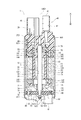
燃料ポンプ1は、モータ部3、ポンプ部4、ハウジング20、ポンプカバー60、及び、カバーエンド40などから構成される。燃料ポンプ1では、モータ部3及びポンプ部4は、ハウジング20、ポンプカバー60、及び、カバーエンド40により形成される空間に収容されている。燃料ポンプ1は、図1の下側に示す吸入口61から図示しない燃料タンク内の燃料を吸入し、図1の上側に示す吐出口41から内燃機関に吐出する。なお、図1では、上側を「天側」、下側を「地側」とする。ハウジング20、ポンプカバー60、及び、カバーエンド40は、特許請求の範囲に記載の「ポンプケース」に相当する。
The fuel pump 1 includes a
ハウジング20は、鉄などの金属により円筒状に形成されている。ハウジング20の二つの端部201、202にポンプカバー60、及び、カバーエンド40が設けられている。
The
ポンプカバー60は、ハウジング20の吸入口61側の端部201を塞いでいる。ポンプカバー60は、ハウジング20の端部201の縁が内側へ加締められることによりハウジング20の内側で固定され、燃料ポンプ1の軸方向への抜けが規制されている。ポンプカバー60は、地側に開口する吸入口61を有している。吸入口61の内側には、ポンプカバー60をシャフト52の回転軸CA52の方向に貫く吸入通路62が形成されている。また、ポンプカバー60のポンプ部4側の面には、吸入通路62と接続する溝63が形成されている。
The
カバーエンド40は、樹脂から成形され、ハウジング20の吐出口41側の端部202を塞いでいる。カバーエンド40は、ハウジング20の端部202の縁が加締められることによりハウジング20の内側で固定され、燃料ポンプ1の軸方向への抜けが規制されている。カバーエンド40は、天側に開口する吐出口41を有している。吐出口41の内側には、カバーエンド40をシャフト52の回転軸CA52の方向に貫く吐出通路42が形成されている。カバーエンド40の吐出通路42が形成されている側とは反対側の端部には、外部からの電力を受電する接続端子38を収容する電気コネクタ部43が設けられている。
The
カバーエンド40のハウジング20の内部側には、略筒状に形成される軸受収容部44が設けられている。軸受収容部44は、内部にシャフト52の端部521及び端部521を回転可能に支持する軸受55を収容する収容空間440を有する。
A bearing
モータ部3は、電力が供給されると発生する磁界を利用して回転トルクを発生する。モータ部3は、ステータ10、ロータ50、シャフト52などから構成されている。なお、第1実施形態による燃料ポンプ1のモータ部3は、ステータ10に対するロータ50の位置をシャフト52の回転によって検出するブラシレスモータである。
The
ステータ10は、円筒状を呈し、ハウジング20内の径方向外側に収容されている。ステータ10は、六個のコア12、六個のボビン、六個の巻線、及び、三個の接続端子などを有している。ステータ10は、これらを樹脂によりモールドすることにより一体に形成される。
The
コア12は、それぞれ板状の鉄など磁性材料が複数枚重なることにより形成されている。コア12は、周方向に並べられ、ロータ50の磁石54に対向する位置に設けられている。
The
ボビン14は、樹脂材料から形成されており、形成時にそれぞれコア12がインサートされてコア12と一体となって設けられる。ボビン14は、吐出口41側に形成される上端部141、コアがインサートされているインサート部142、及び、吸入口61側に形成される下端部143から構成されている。
The
巻線は、例えば表面が絶縁皮膜で被覆された銅線である。一つの巻線は、コア12がインサートされたボビン14に巻回されることによって一つのコイルを形成する。一つの巻線は、ボビン14の上端部141に巻回される上端巻回部161、ボビン14のインサート部142に巻回される図示しないインサート巻回部、及び、ボビン14の下端部143に巻回される下端巻回部163などから構成される。巻線は、電気コネクタ部43に収容されている接続端子38と電気的に接続する。
The winding is, for example, a copper wire whose surface is covered with an insulating film. One winding forms one coil by being wound around the
接続端子38は、カバーエンド40を貫通しボビン14の上端部141に固定されている。第1実施形態による燃料ポンプ1では、接続端子38は三つ設けられ、図示しない電源装置からの3相電力を受電する。
The
ロータ50は、ステータ10の内側に回転可能に収容される。ロータは、鉄心53の周囲に磁石54が設けられる。磁石54は、周方向にN極とS極とが交互に配置されている。第1実施形態では、N極及びS極は2極対、計4極設けられている。
The
シャフト52は、ロータ50の中心軸上に形成された軸穴51に圧入固定されており、ロータ50とともに回転する。シャフト52の吸入口61側の端部522は、ポンプ部4と接続している。
The
シャフト52の端部522は、天地方向に延び平面状に形成される「シャフト側第1当接面」としてのシャフト第1平面523、及び、平面状に形成されシャフト第1平面523に対して略平行に設けられる「シャフト側第2当接面」としてのシャフト第2平面524を有する。また、シャフト52の端部522は、シャフト第1平面523の一の辺とシャフト第2平面524の一の辺とを接続し曲面状に形成されるシャフト第1曲面525、及び、シャフト第1平面523の他の辺とシャフト第2平面524の他の辺とを接続し曲面状に形成されるシャフト第2曲面526を有する。これにより、シャフト52の端部522の回転軸CA52に垂直な方向の断面形状は、略I字状となる。
The
ポンプ部4は、モータ部3が発生する回転トルクを利用して吸入口61から吸入した燃料を加圧しハウジング20内に吐出する。ポンプ部4は、「ポンプケース」としてのポンプケーシング70、インペラ65などから構成されている。
The
ポンプケーシング70は、略円板状に形成され、ポンプカバー60とステータ10との間に設けられている。ポンプケーシング70の中心には、ポンプケーシング70を板厚方向に貫く貫通孔71が形成されている。貫通孔71には、軸受56が嵌め込まれている。軸受56は、シャフト52の端部522を回転可能に支持している。これにより、ロータ50及びシャフト52は、カバーエンド40及びポンプケーシング70に対し回転可能となっている。
また、ポンプケーシング70のインペラ65側の面であって、ポンプカバー60の溝63に対向する位置に溝73が形成されている。溝73には、ポンプケーシング70をシャフト52の回転軸CA52の方向に貫く燃料通路74が連通している。
The
Further, a
インペラ65は、樹脂により略円板状に形成されている。インペラ65は、ポンプカバー60とポンプケーシング70との間のポンプ室72に収容されている。
インペラ65の略中央には、嵌合孔66が形成されている。嵌合孔66は、その断面形状がシャフト52の端部522の断面形状に合うように略I字状に形成されている。嵌合孔66には、シャフト52の端部522が嵌合される。これにより、インペラ65は、シャフト52の回転によってポンプ室72で回転する。インペラ65の詳細な形状は後述する。
The
A
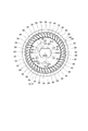
インペラ65は、溝63及び溝73に対応する位置に傾斜面64が複数形成されている。傾斜面64は、図2に示すように、インペラ65の径方向外側の端部に周方向に等間隔に設けられる。
The
第1実施形態による燃料ポンプ1では、接続端子38を介してモータ部3の巻線に電力が供給されるとロータ50及びシャフト52とともにインペラ65が回転する。インペラ65が回転すると、燃料ポンプ1を収容する燃料タンク内の燃料は、吸入口61を経由して溝63に導かれる。溝63に導かれた燃料は、インペラ65の回転により加圧され溝73に導かれる。加圧された燃料は、燃料通路74を通り、ポンプケーシング70とモータ部3との間に形成される中間室75に導かれる。
In the fuel pump 1 according to the first embodiment, the
中間室75に導かれた燃料は、ロータ50とステータ10との間の燃料通路77、シャフト52の外壁とボビン14の内壁144との間の燃料通路78、軸受収容部44の径外方向に形成される燃料通路79を通る。また、中間室75に導かれた燃料は、ハウジング20の内壁とステータ10の外壁との間に形成される燃料通路76を通る。燃料通路76、77、78、79を通る燃料は、吐出通路42及び吐出口41を介して外部に吐出される。
The fuel guided to the
第1実施形態による燃料ポンプ1は、インペラ65の形状に特徴がある。ここでは、図2、3に基づいて、インペラ65の詳細な形状を説明する。図2は、インペラ65の上面図である。図3は、燃料ポンプ1が駆動するときの嵌合孔66とシャフト52との位置関係を示す模式図である。なお、図3(b)〜(d)では、説明の便宜上、嵌合孔66の形状を実際の形状より誇張して示してある。
The fuel pump 1 according to the first embodiment is characterized by the shape of the
インペラ65が有する嵌合孔66は、「インペラ側第1当接面」としてのインペラ第1平面661、「インペラ側第2当接面」としてのインペラ第2平面662、「嵌合孔第1形成面」としてのインペラ第1曲面663、「嵌合孔第2形成面」としてのインペラ第2曲面664から形成される。
The
インペラ第1平面661は、嵌合孔66の中心軸CA66の方向に延びるよう形成される平面である。インペラ第1平面661は、シャフト第1平面523に対向する位置に設けられ、シャフト52が回転するときシャフト第1平面523に当接可能である。
The impeller
インペラ第2平面662は、中心軸CA66の方向に延びるよう形成される平面である。インペラ第2平面662は、インペラ第1平面661に略平行に設けられる。インペラ第2平面662は、シャフト第2平面524に対向する位置に設けられ、シャフト52が回転するときシャフト第2平面524に当接可能である。
The impeller
インペラ第1曲面663は、インペラ第1平面661の中心軸CA66に平行な一の辺とインペラ第2平面662の中心軸CA66に平行な一の辺とを接続する。インペラ第1曲面663は、断面形状が中心軸CA66上の点を中心として径外方向に突出する略円弧状となるよう形成される。インペラ第1曲面663には、略中央に「変形許容空間」としての第1溝665が形成される。
The impeller first
インペラ第2曲面664は、インペラ第1平面661の中心軸CA66に平行な他の一辺とインペラ第2平面662の中心軸CA66に平行な他の一辺とを接続する。インペラ第2曲面664は、断面形状が中心軸CA66上の点を中心として径外方向に突出する略円弧状となるよう形成される。インペラ第2曲面664には、略中央に「変形許容空間」としての第2溝666が形成される。
The impeller second
第1溝665は、インペラ第1曲面663から径外方向に延びるようスリット状に形成される。第1溝665は、嵌合孔66と連通するよう形成され、中心軸CA66の方向にインペラ65を貫通している。
第2溝666は、インペラ第2曲面664から径外方向に延びるようスリット状に形成される。第2溝666は、嵌合孔66と連通するよう形成され、中心軸CA66の方向にインペラ65を貫通している。
第1溝665と第2溝666とは、互いに反対方向に延び、径方向の長さが同じになるよう形成されている。
The
The
The
ここで、第1実施形態による燃料ポンプ1の作用及び効果について図3に基づいて説明する。 Here, the operation and effect of the fuel pump 1 according to the first embodiment will be described with reference to FIG.
第1実施形態による燃料ポンプ1では、図3(a)に示すように、シャフト52に形成されるシャフト第1平面523と嵌合孔66を形成するインペラ第1平面661とが平行となるとき、シャフト52に形成されるシャフト第2平面524と嵌合孔66を形成するインペラ第2平面662との位置関係が平行となるのが望ましい。しかしながら、射出成形による樹脂から形成されるインペラ65では、これらの関係を満たすよう成形することが難しいため、例えば、シャフト第1平面523とインペラ第1平面661とが平行であるとき、シャフト第2平面524とインペラ第2平面662とが平行でない位置関係となる場合がある。
In the fuel pump 1 according to the first embodiment, as shown in FIG. 3A, when the shaft
例えば、図3(b)に示すように、シャフト第1平面523とインペラ第1平面661とは平行となっているが、シャフト第2平面524とインペラ第2平面662とが平行の位置関係になく、インペラ第2平面662とインペラ第2曲面664との交線667が嵌合孔66の中心軸CA66上の点から離れた位置にあるように嵌合孔66が形成される場合がある。
For example, as shown in FIG. 3B, the shaft
図3(b)に示したような嵌合孔66の形状の場合、図3(c)に示すように、シャフト52が実線矢印で示す方向R1の方向にシャフト52が回転すると、シャフト第1平面523とインペラ第1平面661とは当接する一方、シャフト第2平面524とインペラ第2平面662とは離間する。シャフト52とインペラ65とはこの状態でさらに方向R1に回転する。このとき、シャフト第1平面523とインペラ第1平面661との間にシャフト第1平面523からインペラ第1平面に向かう方向に作用力F1が作用する。この作用力F1によりインペラ65は、図3(d)に示すように、第1溝665が拡がるよう変形する。第1溝665の変形によって、嵌合孔66の形状が変化し離間していたシャフト第2平面524とインペラ第2平面662とが当接する。なお、図3(d)には、第1溝665が変形する前における嵌合孔66及び第1溝665の形状を点線で示してある。
ここでは、第1溝665が広がることによってシャフト52の二つの平面がインペラ65の二つの平面に当接することを説明したが、第2溝666についても同様である。
In the case of the shape of the
Here, it has been described that the two flat surfaces of the
(a)第1実施形態による燃料ポンプ1では、シャフト52が嵌合孔66の中で回転しシャフト52が嵌合孔66を形成するインペラ第1平面661またはインペラ第2平面662のいずれか一方に当接するとき、第1溝665または第2溝666が変形し嵌合孔66の形状が変化する。嵌合孔66の形状が変化すると、シャフト52が当接していないインペラ第2平面662またはインペラ第1平面661にシャフト52のシャフト第2平面524またはシャフト第1平面523が当接し、シャフト52は二つの平面が嵌合孔66の内壁に当接する。これにより、シャフト52の回転トルクは、インペラ第1平面661及びインペラ第2平面662の両方に作用し、インペラ65に作用する回転トルクの面圧が小さくなる。したがって、インペラ65に作用する面圧が比較的小さくなり、シャフト52の回転トルクによるインペラ65の破損を防止することができる。
(A) In the fuel pump 1 according to the first embodiment, either the impeller
(b)また、第1実施形態による燃料ポンプ1では、インペラ65が射出成形により成形されるとき、シャフト第1平面523に対するインペラ第1平面661の平行度、及び、シャフト第2平面524に対するインペラ第2平面662の平行度を厳密に管理する必要がなくなる。これにより、燃料ポンプ1の製造工数を低減しつつ、シャフト52の二つの平面が嵌合孔66を形成する二つの平面に当接することができる。したがって、燃料ポンプ1の製造コストを低減することができる。
(B) In the fuel pump 1 according to the first embodiment, when the
(c)また、第1溝665及び第2溝666は、対向するインペラ第1曲面663及びインペラ第2曲面664の中央に形成されている。また、第1溝665と第2溝666とは、中心軸CA66から見て反対方向に同じ長さ延びるよう形成されている。これにより、シャフト52の回転トルクがインペラ第1平面661またはインペラ第2平面662に作用したとき、インペラ65は同じような形状に変形するため、インペラ65の特定の部位に応力が集中することを防止できる。したがって、シャフト52の回転トルクによるインペラ65の破損を防止することができる。
(C) The
(第2実施形態)
次に、本発明の第2実施形態による燃料ポンプを図4に基づいて説明する。第2実施形態は、インペラの形状が第1実施形態と異なる。なお、第1実施形態と実質的に同一の部位には同一の符号を付し、説明を省略する。
(Second Embodiment)
Next, a fuel pump according to a second embodiment of the present invention will be described with reference to FIG. The second embodiment is different from the first embodiment in the shape of the impeller. In addition, the same code | symbol is attached | subjected to the site | part substantially the same as 1st Embodiment, and description is abbreviate | omitted.
第2実施形態による燃料ポンプが備えるインペラ67の上面図を図4に示す。インペラ67の略中央には、嵌合孔68が形成されている。嵌合孔66には、シャフト52の端部522が嵌合される。
FIG. 4 shows a top view of the
嵌合孔68は、その断面形状がシャフト52の端部522の断面形状に合うように略I字状に形成されている。嵌合孔68は、「インペラ側第1当接面」としてのインペラ第1平面681、「インペラ側第2当接面」としてのインペラ第2平面682、「嵌合孔形成面」及び「嵌合孔第1形成面」としてのインペラ第1曲面683、「嵌合孔形成面」及び「嵌合孔第2形成面」としてのインペラ第2曲面684から形成される。
The
インペラ第1平面681は、嵌合孔68の中心軸CA67の方向に延びるよう形成される平面である。インペラ第1平面681は、シャフト第1平面523に対向する位置に設けられ、シャフト52が回転するときシャフト第1平面523に当接可能である。
The impeller
インペラ第2平面682は、中心軸CA67の方向に延びるよう形成される平面である。インペラ第2平面682は、インペラ第1平面681に略平行に設けられる。インペラ第2平面682は、シャフト第2平面524に対向する位置に設けられ、シャフト52が回転するときシャフト第2平面524に当接可能である。
The impeller
インペラ第1曲面683は、インペラ第1平面681の中心軸CA67に平行な一の辺とインペラ第2平面682の中心軸CA67に平行な一の辺とを接続する。インペラ第1曲面683は、断面形状が中心軸CA67上の点を中心として径外方向に突出する略円弧状となるよう形成される。インペラ第1曲面683には、略中央に「変形許容空間」としての第1溝685が形成される。
The impeller first
インペラ第2曲面684は、インペラ第1平面681の中心軸CA67に平行な他の一辺とインペラ第2平面682の中心軸CA67に平行な他の一辺とを接続する。インペラ第2曲面684は、断面形状が中心軸CA67上の点を中心として径外方向に突出する略円弧状となるよう形成される。インペラ第2曲面684には、略中央に「変形許容空間」としての第2溝686が形成される。
The impeller second
第1溝685は、インペラ第1曲面683から径外方向に延びるようスリット状に形成される。第1溝685は、嵌合孔68と連通するよう形成され、中心軸CA67の方向にインペラ67を貫通している。第2溝686は、インペラ第2曲面684から径外方向に延びるようスリット状に形成される。第2溝686は、嵌合孔68と連通するよう形成され、中心軸CA67の方向にインペラ67を貫通している。
The
第1溝685と第2溝686とは、互いに反対方向に延び、径方向の長さが同じになるよう形成されている。このとき、中心軸CA67上に中心を有しインペラ67の複数の傾斜面64の径方向内側の部位を結ぶ仮想円を仮想円VL64とし、中心軸CA67上に中心を有しインペラ第1曲面683及びインペラ第2曲面684上を通る仮想円を仮想円VL68とすると、第1溝685を形成する径方向外側の壁面687及び第2溝686を形成する径方向外側の壁面688は、図4に示すように、仮想円VL64及び仮想円VL68から等距離(図4の距離D2)の位置にある中間仮想円VL67より径内方向に形成される。
The
第2実施形態による燃料ポンプでは、第1溝685及び第2溝686は、中間仮想円VL67より径内方向に形成されている。これにより、インペラ67は、シャフト52からの作用によって適度に変形することができる。したがって、第2実施形態による燃料ポンプは、第1実施形態と同じ効果を奏するとともに第1実施形態に比べ変形許容量が大きくなり、シャフト52の回転トルクによるインペラ67の破損をさらに防止することができる。
In the fuel pump according to the second embodiment, the
(第3実施形態)
次に、本発明の第3実施形態による燃料ポンプを図5に基づいて説明する。第3実施形態は、インペラの形状が第1実施形態と異なる。なお、第1実施形態と実質的に同一の部位には同一の符号を付し、説明を省略する。
(Third embodiment)
Next, a fuel pump according to a third embodiment of the present invention will be described with reference to FIG. The third embodiment differs from the first embodiment in the shape of the impeller. In addition, the same code | symbol is attached | subjected to the site | part substantially the same as 1st Embodiment, and description is abbreviate | omitted.
第3実施形態による燃料ポンプでは、インペラ85は、傾斜面84、嵌合孔86、及び、「変形許容空間」としての貫通孔87を有している。
傾斜面84は、第1実施形態の傾斜面64と同様に、溝63及び溝73に対応する位置に複数形成される。
嵌合孔86は、第1実施形態の嵌合孔66と同様に、その断面形状がシャフト52の端部522の断面形状に合うように略I字状に形成されている。嵌合孔86は、シャフト第1平面523に当接可能な「インペラ側第1当接面」としてのインペラ第1平面861、シャフト第2平面524に当接可能な「インペラ側第2当接面」としてのインペラ第2平面862から形成されている。
In the fuel pump according to the third embodiment, the
A plurality of
Similar to the
貫通孔87は、中心軸CA85の方向に延びるよう形成され、中心軸CA85の方向にインペラ85を貫通する。第2実施形態による燃料ポンプでは、貫通孔87は、六個設けられ、嵌合孔86の径外方向に嵌合孔86の中心軸CA85上の点を中心とする円周上に等間隔に位置している。また、貫通孔87の一の貫通孔は、中心軸CA85上の点を対称点として他の貫通孔に対して点対称となるよう設けられている。
The through
第3実施形態による燃料ポンプでは、シャフト52がインペラ85の嵌合孔86の中で回転するとき、シャフト52のシャフト第1平面523及びシャフト第2平面524のうち一つの平面のみが嵌合孔86を形成する内壁に当接する場合がある。この場合、貫通孔87の変形によって嵌合孔86の形状が変化し、シャフト52の二つの平面のうち当接していなかった平面が嵌合孔86を形成する内壁に当接する。これにより、第2実施形態による燃料ポンプは、第1実施形態の効果(a)、(b)と同じ効果を奏する。
In the fuel pump according to the third embodiment, when the
また、複数の貫通孔87は、中心軸CA85上の点を中心とする円周上に等間隔に位置し、貫通孔87の一の貫通孔は、中心軸CA85上の点を対称点として他の貫通孔に対して点対称となるよう設けられている。これにより、シャフト52の回転トルクがインペラ第1平面661またはインペラ第2平面662に作用したとき、インペラ65は同じような形状に変形するため、インペラ65の特定の部位に力が作用することを防止できる。したがって、シャフト52の回転トルクによるインペラ65の破損を防止することができる。
Further, the plurality of through
(第4実施形態)
次に、本発明の第4実施形態による燃料ポンプを図6に基づいて説明する。第4実施形態は、インペラの形状が第3実施形態と異なる。なお、第3実施形態と実質的に同一の部位には同一の符号を付し、説明を省略する。
(Fourth embodiment)
Next, a fuel pump according to a fourth embodiment of the present invention will be described with reference to FIG. The fourth embodiment differs from the third embodiment in the shape of the impeller. In addition, the same code | symbol is attached | subjected to the site | part substantially the same as 3rd Embodiment, and description is abbreviate | omitted.
第4実施形態による燃料ポンプが備えるインペラ88の上面図を図6に示す。インペラ88は、傾斜面84、嵌合孔86、及び、「変形許容空間」としての貫通孔89を有している。
A top view of the
貫通孔89は、中心軸CA88の方向に延びるよう形成され、中心軸CA88の方向にインペラ88を貫通する。第4実施形態による燃料ポンプでは、貫通孔89は、六個設けられ、嵌合孔86の径外方向に嵌合孔86の中心軸CA88上の点を中心とする円周上に等間隔に位置している。
The through
また、中心軸CA88上に中心を有しインペラ88の径方向外側に形成されている複数の傾斜面84の径方向内側の部位を結ぶ仮想円を仮想円VL84とし、中心軸CA88上に中心を有し嵌合孔86の「嵌合孔形成面」としてのインペラ第1曲面863及び「嵌合孔形成面」としてのインペラ第2曲面864上を通る仮想円を仮想円VL86とすると、貫通孔89は、図6に示すように、仮想円VL84及び仮想円VL86から等距離(図6の距離D4)の位置にある中間仮想円VL88より径内方向に形成される。
Further, a virtual circle having a center on the central axis CA88 and connecting the radially inner portions of the plurality of
第4実施形態による燃料ポンプでは、貫通孔89は、中間仮想円VL88より径内方向に形成されている。これにより、インペラ88は、シャフト52からの作用によって適度に変形することができる。したがって、第4実施形態による燃料ポンプは、第3実施形態と同じ効果を奏するとともに第3実施形態に比べ変形許容量が大きくなり、シャフト52の回転トルクによるインペラ88の破損をさらに防止することができる。
In the fuel pump according to the fourth embodiment, the through
(第5実施形態)
次に、本発明の第5実施形態による燃料ポンプを図7に基づいて説明する。第5実施形態は、シャフトの端部の形状及びインペラの形状が第3実施形態と異なる。なお、第3実施形態と実質的に同一の部位には同一の符号を付し、説明を省略する。
(Fifth embodiment)
Next, a fuel pump according to a fifth embodiment of the present invention will be described with reference to FIG. The fifth embodiment differs from the third embodiment in the shape of the end of the shaft and the shape of the impeller. In addition, the same code | symbol is attached | subjected to the site | part substantially the same as 3rd Embodiment, and description is abbreviate | omitted.
第5実施形態による燃料ポンプが備えるインペラ95の上面図を図7に示す。インペラ95は、傾斜面94、嵌合孔96、及び、「変形許容空間」としての貫通孔991、992、993、994、995を有している。
A top view of the
傾斜面94は、ポンプカバー60に形成されている溝63及びポンプケーシング70に形成されている溝73に対応する位置に複数形成されている。
A plurality of
嵌合孔96は、その断面形状がシャフト92の一方の端部922の断面形状に合うように略D字状に形成されている。嵌合孔96は、「シャフト側第3当接面」としてのシャフト第3平面923に当接可能な「インペラ側第3当接面」としてのインペラ第3平面961、シャフト第3平面923の中心軸CA95に略平行な両端を断面形状が略円弧状の曲面で接続するシャフト第3曲面925に沿うよう形成される「嵌合孔形成面」としてのインペラ曲面963から形成される。
The
貫通孔991、992、993、994、995は、中心軸CA95の方向に延びるよう形成され、中心軸CA95の方向にインペラ85を貫通する。第5実施形態による燃料ポンプでは、インペラ95は五個の貫通孔を有する。貫通孔991、992、993、994、995は、嵌合孔96の径外方向に嵌合孔96の中心軸CA95上の点を中心とする円周上に等間隔に位置している。また、インペラ95が有する貫通孔のうち、二つの貫通孔992、995は、インペラ第3平面961とインペラ曲面963とが接続する部位962、964の近傍に設けられる。
The through
また、中心軸CA95上に中心を有し複数の傾斜面94の径方向内側の部位を結ぶ仮想円を仮想円VL94とし、中心軸CA95上に中心を有しインペラ曲面963上を通る仮想円を仮想円VL96とすると、貫通孔991、992、993、994、995は、図7に示すように、仮想円VL94及び仮想円VL96から等距離(図7の距離D5)の位置にある中間仮想円VL98より径内方向に形成される。
Further, a virtual circle connecting the radially inner portions of the plurality of
第5実施形態による燃料ポンプでは、インペラ95は断面形状がD字状のシャフト92の端部に対して嵌合孔96の断面形状がD字状に形成されている。このとき、インペラ95が有する貫通孔は、嵌合孔96の形状に合わせて奇数個の五個形成されている。これにより、シャフトの端部が嵌合する嵌合孔の形状が両側で当接するI字状と異なり一辺でのみ当接するD字状であっても、シャフト第3平面923がインペラ第3平面961に当接するようインペラ95が変形することができる。したがって、第5実施形態は、第3実施形態と同じ効果を奏する。
In the fuel pump according to the fifth embodiment, the
また、第5実施形態による燃料ポンプでは、貫通孔991、992、993、994、995は、中間仮想円VL98より径内方向に形成されている。これにより、インペラ95は、シャフト52からの作用によって適度に変形することができる。したがって、第5実施形態による燃料ポンプは、シャフト92の回転トルクによるインペラ95の破損をさらに防止することができる。
Further, in the fuel pump according to the fifth embodiment, the through
また、インペラ95には、嵌合孔96の形状に合わせて貫通孔は五個形成されている。これにより、インペラ95の全体の重量バランスが均等に保たれ、インペラ95の回転時に振動などの不具合が発生することを防止することができる。
Further, five through holes are formed in the
(他の実施形態)
(ア)第1、2実施形態では、「変形許容空間」として第1溝及び第2溝が設けられるとした。また、第3、4、5実施形態では、「変形許容空間」としての複数の貫通孔が設けられるとした。しかしながら、「変形許容空間」の形状はこれに限定されない。インペラに設けられ、シャフトとインペラとが当接するときインペラの弾性変形可能な量を大きくするよう変形する空間であればよい。
(Other embodiments)
(A) In the first and second embodiments, the first groove and the second groove are provided as the “deformable space”. In the third, fourth, and fifth embodiments, a plurality of through-holes as “deformation allowable spaces” are provided. However, the shape of the “deformable space” is not limited to this. Any space provided on the impeller and capable of being deformed so as to increase the amount of elastic deformation of the impeller when the shaft and the impeller contact each other may be used.
(イ)上述の実施形態では、「シャフト側第1当接面」としてのシャフト第1平面、「シャフト側第2当接面」としてのシャフト第2平面、「インペラ側第1当接面」としてのインペラ第1平面、「インペラ側第2当接面」としてのインペラ第2平面は、平面状に形成されるとした。しかしながら、これらの面は平面状に形成されていなくてもよい。曲面上であってもよく、「シャフト側第1当接面」と「インペラ側第1当接面」とが当接可能であり、「シャフト側第2当接面」と「インペラ側第2当接面」とが当接可能なよう形成されればよい。 (A) In the above-described embodiment, the shaft first plane as the “shaft side first contact surface”, the shaft second plane as the “shaft side second contact surface”, and the “impeller side first contact surface” The impeller first plane as the impeller second plane as the “impeller side second contact surface” is formed in a planar shape. However, these surfaces do not have to be formed flat. It may be on a curved surface, and the “shaft side first contact surface” and the “impeller side first contact surface” can contact each other, and the “shaft side second contact surface” and the “impeller side second contact” What is necessary is just to form so that a contact surface "can contact | abut.
(ウ)上述の実施形態では、「シャフト側第1当接面」としてのシャフト第1平面と「シャフト側第2当接面」としてのシャフト第2平面とは、略平行に形成されるとした。しかしながら、平行でなくてもよい。 (C) In the above-described embodiment, the shaft first plane as the “shaft side first contact surface” and the shaft second plane as the “shaft side second contact surface” are formed substantially in parallel. did. However, it does not have to be parallel.
(エ)第1、2実施形態では、「変形許容空間」は複数形成されるとした。しかしながら、一つであってもよい。 (D) In the first and second embodiments, a plurality of “deformable spaces” are formed. However, it may be one.
(オ)第1、2実施形態では、第1溝及び第2溝は、インペラ第1曲面及びインペラ第2曲面の中央に形成されるとした。しかしながら、第1溝及び第2溝が形成される場所はこれに限定されない。 (E) In the first and second embodiments, the first groove and the second groove are formed at the center of the impeller first curved surface and the impeller second curved surface. However, the place where the first groove and the second groove are formed is not limited to this.
(カ)第1、2実施形態では、第1溝と第2溝とは、径方向の長さが同じであり、互いに反対方向に延びるよう形成されるとした。しかしながら、第1溝と第2溝との関係はこれに限定されない。 (F) In the first and second embodiments, the first groove and the second groove have the same radial length and are formed to extend in opposite directions. However, the relationship between the first groove and the second groove is not limited to this.
(キ)第3、4、5実施形態では、複数の貫通孔は、インペラの中心軸上の点を中心とする円周上に等間隔で設けられ、互いに点対称に配置するとした。しかしながら、複数の貫通孔が配置される場所はこれに限定されない。 (G) In the third, fourth, and fifth embodiments, the plurality of through holes are provided at equal intervals on a circumference centered on a point on the central axis of the impeller, and are arranged symmetrically with respect to each other. However, the place where the plurality of through holes are arranged is not limited to this.
(ク)第3、4実施形態では、貫通孔は六個形成されるとした。また、第5実施形態では、貫通孔は五個形成されるとした。このように、インペラが有する嵌合孔の形状がI字状の場合、偶数個形成されることが望ましい。また、インペラが有する嵌合孔の形状がD字状の場合、奇数個形成されることが望ましい。しかしながら、貫通孔が形成される数はこれに限定されない。 (H) In the third and fourth embodiments, six through holes are formed. In the fifth embodiment, five through holes are formed. Thus, when the shape of the fitting hole of the impeller is I-shaped, it is desirable to form an even number. Moreover, when the shape of the fitting hole which an impeller has is D shape, it is desirable to form an odd number. However, the number of through holes formed is not limited to this.
(ケ)上述の実施形態では、燃料ポンプが備えるモータ部は、ブラシレスモータであるとした。しかしながら、シャフトを正方向及び逆方向の二方向に回転するモータであれば、ブラシレスモータでなくてもよい。 (K) In the above-described embodiment, the motor unit included in the fuel pump is a brushless motor. However, the motor need not be a brushless motor as long as the motor rotates the shaft in two directions, the forward direction and the reverse direction.
以上、本発明はこのような実施形態に限定されるものではなく、その要旨を逸脱しない範囲で種々の形態により実施可能である。 As mentioned above, this invention is not limited to such embodiment, It can implement with a various form in the range which does not deviate from the summary.
1 ・・・燃料ポンプ、
52、92 ・・・シャフト、
523 ・・・シャフト第1平面(シャフト側第1当接面)、
524 ・・・シャフト第2平面(シャフト側第2当接面)、
923 ・・・シャフト第3平面(シャフト側第3当接面)、
65 ・・・インペラ、
66、68、86、96・・・嵌合孔、
661、681 ・・・インペラ第1平面(インペラ側当接面、インペラ側第1当接面)、
662、682 ・・・インペラ第2平面(インペラ側当接面、インペラ側第2当接面)、
961 ・・・インペラ第3平面(インペラ側当接面、インペラ側第3当接面)、
665、685 ・・・第1溝(変形許容空間)、
666、686 ・・・第2溝(変形許容空間)、
87、89、991、992、993、994、995・・・貫通孔(変形許容空間)。
1 ... Fuel pump,
52, 92 ... Shaft,
523 ... shaft first plane (first contact surface sheet Yafuto side)
524 ... shaft second plane (second contact surface sheet Yafuto side)
923 ... Shaft third plane (third contact surface sheet Yafuto side)
65 ・ ・ ・ Impeller,
66, 68, 86, 96 ... fitting holes,
661, 681 ... impeller first plane (impeller side contact surface, impeller side first contact surface),
662, 682... Impeller second plane (impeller side contact surface, impeller side second contact surface),
961 ... Impeller third plane (impeller side contact surface, impeller side third contact surface),
665, 685... First groove (deformable space),
666, 686 ... second groove (deformable space),
87, 89, 991, 992, 993, 994, 995... Through-hole (deformable space).
Claims (6)
複数の巻線が巻回され、前記ポンプケースの内部に収容される筒状のステータ(10)と、
前記ステータの径方向内側に回転可能に設けられるロータ(50)と、
前記ロータと同軸に設けられ、前記ロータと一体に回転するシャフト(52、92)と、
前記ポンプ室に回転可能に収容され、前記シャフトの一方の端部(522、922)が嵌合する嵌合孔(66、68、86、96)を有し、前記シャフトとは当該嵌合孔におけるクリアランスの範囲で周方向に相対移動可能に設けられ、前記シャフトとともに回転すると前記吸入口から吸入した燃料を加圧し前記吐出口から吐出するインペラ(65、67、85、88、95)と、
を備え、
前記シャフトは、一方の端部に前記インペラに当接可能なシャフト側当接面(523、524、923)を有し、
前記嵌合孔は、前記シャフト側当接面に対向する位置に設けられ前記シャフト側当接面に当接可能なインペラ側当接面(661、662、681、682、961)から形成され、
前記インペラは、前記嵌合孔の径外方向に形成され前記インペラの中心軸方向に前記インペラを貫通し前記シャフト側当接面と前記インペラ側当接面とが当接すると変形する変形許容空間(665、666、685、686、87、89、991、992、993、994、995)を有することを特徴とする燃料ポンプ。 Pump case (20, 40, 60, 70) having a suction port (61) for sucking fuel, a discharge port (41) for discharging fuel, and a pump chamber (72) communicating with the suction port and the discharge port )When,
A cylindrical stator (10) wound with a plurality of windings and housed inside the pump case;
A rotor (50) rotatably provided on the radially inner side of the stator;
A shaft (52, 92) provided coaxially with the rotor and rotating integrally with the rotor;
There is a fitting hole (66, 68, 86, 96) that is rotatably accommodated in the pump chamber and into which one end (522, 922) of the shaft is fitted, and the shaft is the fitting hole. An impeller (65, 67, 85, 88, 95) that is provided so as to be relatively movable in the circumferential direction within a clearance range in the above, and pressurizes fuel sucked from the suction port and discharges from the discharge port when rotated together with the shaft;
With
The shaft has a shaft side contact surface (523, 524, 923) capable of contacting the impeller at one end,
The fitting hole is formed from an impeller side contact surface (661, 662, 681, 682, 961) provided at a position facing the shaft side contact surface and capable of contacting the shaft side contact surface,
The impeller is formed in a radially outward direction of the fitting hole, passes through the impeller in a central axis direction of the impeller, and deforms when the shaft-side contact surface and the impeller-side contact surface come into contact with each other. (665, 666, 685, 686, 87, 89, 991, 992, 993, 994, 995).
前記嵌合孔は、前記シャフト側第1当接面に対向する位置に設けられ前記シャフト側第1当接面に当接可能な前記インペラ側当接面としてのインペラ側第1当接面(661、681)、及び、前記シャフト側第2当接面に対向する位置に設けられ前記シャフト側第2当接面に当接可能な前記インペラ側当接面としてのインペラ側第2当接面(662、682)から形成され、
前記変形許容空間は、前記シャフト側第1当接面と前記インペラ側第1当接面、または、前記シャフト側第2当接面と前記インペラ側第2当接面とが当接すると変形することを特徴とする請求項1に記載の燃料ポンプ。 The shaft is formed at a position different from the shaft side first contact surface (523) as the shaft side contact surface capable of contacting the impeller and the shaft side first contact surface. A shaft-side second contact surface (524) as the shaft-side contact surface capable of contact;
The fitting hole is provided at a position facing the shaft-side first contact surface, and the impeller-side first contact surface as the impeller-side contact surface capable of contacting the shaft-side first contact surface ( 661, 681), and the impeller side second abutment surface as the impeller side abutment surface provided at a position facing the shaft side second abutment surface and capable of abutting against the shaft side second abutment surface (662, 682),
The deformation allowable space is deformed when the shaft-side first contact surface and the impeller-side first contact surface, or the shaft-side second contact surface and the impeller-side second contact surface contact each other. The fuel pump according to claim 1.
前記嵌合孔は、前記シャフト側第1当接面に対向する位置に設けられ前記シャフト側第1当接面に当接可能な前記インペラ側当接面としてのインペラ側第1当接面(861)、及び、前記シャフト側第2当接面に対向する位置に設けられ前記シャフト側第2当接面に当接可能な前記インペラ側当接面としてのインペラ側第2当接面(862)から形成され、
前記変形許容空間は、偶数個形成され、前記シャフト側第1当接面と前記インペラ側第1当接面、または、前記シャフト側第2当接面と前記インペラ側第2当接面とが当接すると変形し、
複数の前記変形許容空間の一の変形許容空間は、複数の前記変形許容空間の他の変形許容空間に対し前記インペラの中心軸(CA85、CA88)上の点を対称点とする点対称の位置に形成されることを特徴とする請求項1に記載の燃料ポンプ。 The shaft is formed at a position different from the shaft side first contact surface (523) as the shaft side contact surface capable of contacting the impeller and the shaft side first contact surface. A shaft-side second contact surface (524) as the shaft-side contact surface capable of contact;
The fitting hole is provided at a position facing the shaft-side first contact surface, and the impeller-side first contact surface as the impeller-side contact surface capable of contacting the shaft-side first contact surface ( 861), and an impeller-side second contact surface (862) as the impeller-side contact surface provided at a position facing the shaft-side second contact surface and capable of contacting the shaft-side second contact surface. )
The even number of deformation permissible spaces are formed, and the shaft side first contact surface and the impeller side first contact surface, or the shaft side second contact surface and the impeller side second contact surface are formed. Deforms when abutting,
One deformation allowing space of a plurality of the deformation allowing space, the center axis (CA85, CA88) position of point symmetry of symmetrical point a point on the impeller to another modification allowing space for a plurality of the deformation allowing space The fuel pump according to claim 1 , wherein the fuel pump is formed as follows.
前記嵌合孔は、前記シャフト側第3当接面に対向する位置に設けられ前記シャフト側第3当接面に当接可能な前記インペラ側当接面としてのインペラ側第3当接面(961)から形成され、
前記変形許容空間は、奇数個形成され、前記シャフト側第3当接面と前記インペラ側第3当接面とが当接すると変形することを特徴とする請求項1に記載の燃料ポンプ。 The shaft has a shaft side third contact surface (923) as the shaft side contact surface capable of contacting the impeller,
The fitting hole is provided at a position facing the shaft-side third contact surface, and the impeller-side third contact surface as the impeller-side contact surface capable of contacting the shaft-side third contact surface ( 961),
2. The fuel pump according to claim 1 , wherein the deformation-permissible space is formed in an odd number, and is deformed when the shaft-side third contact surface and the impeller-side third contact surface come into contact with each other.
前記インペラの径方向外側の端部に設けられ前記インペラの回転を利用して燃料を加圧し突出する複数の傾斜面(84、94)と、
断面形状が前記嵌合孔の中心軸上に中心を有する円弧状となるよう形成され前記インペラ側当接面の両端を接続する嵌合孔形成面(863、864、963)を有し、
前記変形許容空間は、前記嵌合孔の中心軸上に中心を有し前記傾斜面の径方向内側の部位を結ぶ仮想円(VL84、VL94)及び前記嵌合孔の中心軸上に中心を有し前記嵌合孔形成面の径方向外側の部位を結ぶ仮想円(VL86、VL96)から等距離の位置にある中間仮想円(VL88、VL98)より径内方向に位置することを特徴とする請求項1から5のいずれか一項に記載の燃料ポンプ。 The impeller is
A plurality of inclined surfaces ( 84, 94) provided at an end portion on the radially outer side of the impeller and protruding by pressurizing fuel using rotation of the impeller;
A fitting hole forming surface ( 863, 864, 963) connecting the both ends of the impeller side contact surface is formed so that the cross-sectional shape is an arc shape having a center on the center axis of the fitting hole;
The deformation-allowed space has a center on the center axis of the fitting hole and a virtual circle ( VL84, VL94) that has a center on the center axis of the fitting hole and connects a radially inner portion of the inclined surface. And is located radially inward from an intermediate virtual circle ( VL88, VL98) that is equidistant from a virtual circle ( VL86, VL96) that connects the radially outer portions of the fitting hole forming surface. The fuel pump according to any one of claims 1 to 5 .
Priority Applications (3)
| Application Number | Priority Date | Filing Date | Title |
|---|---|---|---|
| JP2014095859A JP6135593B2 (en) | 2013-09-24 | 2014-05-07 | Fuel pump |
| PCT/JP2014/004601 WO2015045294A1 (en) | 2013-09-24 | 2014-09-08 | Fuel pump |
| US15/024,132 US20160238016A1 (en) | 2013-09-24 | 2014-09-08 | Fuel pump |
Applications Claiming Priority (3)
| Application Number | Priority Date | Filing Date | Title |
|---|---|---|---|
| JP2013196615 | 2013-09-24 | ||
| JP2013196615 | 2013-09-24 | ||
| JP2014095859A JP6135593B2 (en) | 2013-09-24 | 2014-05-07 | Fuel pump |
Publications (3)
| Publication Number | Publication Date |
|---|---|
| JP2015086860A JP2015086860A (en) | 2015-05-07 |
| JP2015086860A5 JP2015086860A5 (en) | 2015-11-26 |
| JP6135593B2 true JP6135593B2 (en) | 2017-05-31 |
Family
ID=52742469
Family Applications (1)
| Application Number | Title | Priority Date | Filing Date |
|---|---|---|---|
| JP2014095859A Expired - Fee Related JP6135593B2 (en) | 2013-09-24 | 2014-05-07 | Fuel pump |
Country Status (3)
| Country | Link |
|---|---|
| US (1) | US20160238016A1 (en) |
| JP (1) | JP6135593B2 (en) |
| WO (1) | WO2015045294A1 (en) |
Families Citing this family (9)
| Publication number | Priority date | Publication date | Assignee | Title |
|---|---|---|---|---|
| JP6064847B2 (en) * | 2013-09-17 | 2017-01-25 | 株式会社デンソー | Fuel pump |
| JP6056719B2 (en) * | 2013-09-17 | 2017-01-11 | 株式会社デンソー | Fuel pump |
| JP6361583B2 (en) * | 2015-05-28 | 2018-07-25 | 株式会社デンソー | Fuel pump |
| JP2016223323A (en) * | 2015-05-28 | 2016-12-28 | 株式会社デンソー | Fuel pump |
| JP2017008736A (en) * | 2015-06-17 | 2017-01-12 | 株式会社デンソー | Fuel pump |
| JP2017008734A (en) * | 2015-06-17 | 2017-01-12 | 株式会社デンソー | Fuel pump |
| JP6308177B2 (en) * | 2015-06-26 | 2018-04-11 | 株式会社デンソー | Rotor |
| JP6786436B2 (en) * | 2017-04-07 | 2020-11-18 | 愛三工業株式会社 | Fuel pump |
| DE102018202276B4 (en) * | 2018-02-14 | 2023-05-04 | Ti Automotive Technology Center Gmbh | Liquid pump with vibration damping element |
Family Cites Families (13)
| Publication number | Priority date | Publication date | Assignee | Title |
|---|---|---|---|---|
| JPS5510637Y2 (en) * | 1974-05-17 | 1980-03-07 | ||
| JPS586991U (en) * | 1981-07-08 | 1983-01-17 | 株式会社日立製作所 | rotary pump |
| JPS60156999A (en) * | 1984-01-25 | 1985-08-17 | Nippon Radiator Co Ltd | Fan fitting structure of motor fan |
| JPS6212791U (en) * | 1985-07-08 | 1987-01-26 | ||
| JPS63177693U (en) * | 1987-05-01 | 1988-11-17 | ||
| DE10019909A1 (en) * | 2000-04-20 | 2001-10-25 | Mannesmann Vdo Ag | Pump, esp. fuel pump or windscreen washer liquid for motor vehicles has rotor with elements to move its outer edge relative to the rotor shaft |
| JP2003220578A (en) * | 2002-01-25 | 2003-08-05 | Hitachi Koki Co Ltd | Power tool |
| JP4067994B2 (en) * | 2003-03-27 | 2008-03-26 | 愛三工業株式会社 | Fuel pump |
| US6984099B2 (en) * | 2003-05-06 | 2006-01-10 | Visteon Global Technologies, Inc. | Fuel pump impeller |
| JP4832156B2 (en) * | 2006-05-09 | 2011-12-07 | 愛三工業株式会社 | Fuel pump |
| JP2007315692A (en) * | 2006-05-26 | 2007-12-06 | Max Co Ltd | Rotating fan and blower |
| JP4623217B2 (en) * | 2008-08-06 | 2011-02-02 | 株式会社デンソー | Fuel supply pump |
| JP6038689B2 (en) * | 2013-03-07 | 2016-12-07 | 愛三工業株式会社 | Rotating body |
-
2014
- 2014-05-07 JP JP2014095859A patent/JP6135593B2/en not_active Expired - Fee Related
- 2014-09-08 US US15/024,132 patent/US20160238016A1/en not_active Abandoned
- 2014-09-08 WO PCT/JP2014/004601 patent/WO2015045294A1/en active Application Filing
Also Published As
| Publication number | Publication date |
|---|---|
| WO2015045294A1 (en) | 2015-04-02 |
| US20160238016A1 (en) | 2016-08-18 |
| JP2015086860A (en) | 2015-05-07 |
Similar Documents
| Publication | Publication Date | Title |
|---|---|---|
| JP6135593B2 (en) | Fuel pump | |
| US7560839B2 (en) | Electric motor and fuel pump having the same | |
| JP5652671B2 (en) | Motor and fuel pump using the same | |
| JP5672510B2 (en) | Brushless motor and fuel pump using the same | |
| US9178397B2 (en) | Brushless motor with crossing wire holder | |
| JP2010059969A (en) | Fuel pump | |
| JP6056719B2 (en) | Fuel pump | |
| US20160169248A1 (en) | Pump And Cleaning Apparatus | |
| US10148150B2 (en) | Liquid pump | |
| JP2019122104A (en) | Rotor of rotary electric machine | |
| JP2013074791A (en) | Rotor having shaft slip inhibition structure and motor having the same | |
| US10250090B2 (en) | Rotor, motor, pump and cleaning apparatus | |
| JP2007209128A (en) | Motor and fuel pump employing the same | |
| WO2015040819A1 (en) | Fuel pump | |
| JP5927432B2 (en) | Motor and pump equipped with the same | |
| US10408219B2 (en) | Fuel pump | |
| US20160369818A1 (en) | Fuel pump | |
| US9581164B2 (en) | Manufacturing method for fuel pump | |
| JP3972251B2 (en) | Electric motor and fuel pump using the same | |
| JP2017014931A (en) | Fuel pump | |
| JP6131797B2 (en) | Fuel pump | |
| WO2020049972A1 (en) | Interior permanent magnet motor for superchargers | |
| US20160172909A1 (en) | Motor, pump and cleaning apparatus | |
| JP5929529B2 (en) | Fuel pump | |
| KR20220118213A (en) | Rotor assembly for motor |
Legal Events
| Date | Code | Title | Description |
|---|---|---|---|
| A621 | Written request for application examination |
Free format text: JAPANESE INTERMEDIATE CODE: A621 Effective date: 20150319 |
|
| A521 | Written amendment |
Free format text: JAPANESE INTERMEDIATE CODE: A523 Effective date: 20151007 |
|
| A131 | Notification of reasons for refusal |
Free format text: JAPANESE INTERMEDIATE CODE: A131 Effective date: 20160329 |
|
| A521 | Written amendment |
Free format text: JAPANESE INTERMEDIATE CODE: A523 Effective date: 20160530 |
|
| A131 | Notification of reasons for refusal |
Free format text: JAPANESE INTERMEDIATE CODE: A131 Effective date: 20161025 |
|
| A521 | Written amendment |
Free format text: JAPANESE INTERMEDIATE CODE: A523 Effective date: 20161222 |
|
| TRDD | Decision of grant or rejection written | ||
| A01 | Written decision to grant a patent or to grant a registration (utility model) |
Free format text: JAPANESE INTERMEDIATE CODE: A01 Effective date: 20170328 |
|
| A61 | First payment of annual fees (during grant procedure) |
Free format text: JAPANESE INTERMEDIATE CODE: A61 Effective date: 20170410 |
|
| R151 | Written notification of patent or utility model registration |
Ref document number: 6135593 Country of ref document: JP Free format text: JAPANESE INTERMEDIATE CODE: R151 |
|
| LAPS | Cancellation because of no payment of annual fees |