JP6135391B2 - Imaging apparatus, image processing apparatus, image processing method, and program - Google Patents
Imaging apparatus, image processing apparatus, image processing method, and program Download PDFInfo
- Publication number
- JP6135391B2 JP6135391B2 JP2013169038A JP2013169038A JP6135391B2 JP 6135391 B2 JP6135391 B2 JP 6135391B2 JP 2013169038 A JP2013169038 A JP 2013169038A JP 2013169038 A JP2013169038 A JP 2013169038A JP 6135391 B2 JP6135391 B2 JP 6135391B2
- Authority
- JP
- Japan
- Prior art keywords
- image
- frame
- information
- processing
- end frame
- Prior art date
- Legal status (The legal status is an assumption and is not a legal conclusion. Google has not performed a legal analysis and makes no representation as to the accuracy of the status listed.)
- Active
Links
Images


Classifications
-
- H—ELECTRICITY
- H04—ELECTRIC COMMUNICATION TECHNIQUE
- H04N—PICTORIAL COMMUNICATION, e.g. TELEVISION
- H04N5/00—Details of television systems
- H04N5/222—Studio circuitry; Studio devices; Studio equipment
- H04N5/262—Studio circuits, e.g. for mixing, switching-over, change of character of image, other special effects ; Cameras specially adapted for the electronic generation of special effects
- H04N5/2621—Cameras specially adapted for the electronic generation of special effects during image pickup, e.g. digital cameras, camcorders, video cameras having integrated special effects capability
-
- H—ELECTRICITY
- H04—ELECTRIC COMMUNICATION TECHNIQUE
- H04N—PICTORIAL COMMUNICATION, e.g. TELEVISION
- H04N23/00—Cameras or camera modules comprising electronic image sensors; Control thereof
- H04N23/60—Control of cameras or camera modules
- H04N23/63—Control of cameras or camera modules by using electronic viewfinders
- H04N23/631—Graphical user interfaces [GUI] specially adapted for controlling image capture or setting capture parameters
-
- H—ELECTRICITY
- H04—ELECTRIC COMMUNICATION TECHNIQUE
- H04N—PICTORIAL COMMUNICATION, e.g. TELEVISION
- H04N5/00—Details of television systems
- H04N5/76—Television signal recording
- H04N5/765—Interface circuits between an apparatus for recording and another apparatus
- H04N5/77—Interface circuits between an apparatus for recording and another apparatus between a recording apparatus and a television camera
- H04N5/772—Interface circuits between an apparatus for recording and another apparatus between a recording apparatus and a television camera the recording apparatus and the television camera being placed in the same enclosure
-
- H—ELECTRICITY
- H04—ELECTRIC COMMUNICATION TECHNIQUE
- H04N—PICTORIAL COMMUNICATION, e.g. TELEVISION
- H04N23/00—Cameras or camera modules comprising electronic image sensors; Control thereof
- H04N23/60—Control of cameras or camera modules
- H04N23/69—Control of means for changing angle of the field of view, e.g. optical zoom objectives or electronic zooming
Description
本開示は、撮像装置、画像処理装置、および画像処理方法、並びにプログラムに関する。特に、動画撮影や微速度(Time Lapse)撮影時の各画像フレームのアングルやズームなどの設定を伴う撮影制御処理、あるいは撮影画像の編集処理などを行う撮像装置、画像処理装置、および画像処理方法、並びにプログラムに関する。 The present disclosure relates to an imaging apparatus, an image processing apparatus, an image processing method, and a program. In particular, an imaging device, an image processing device, and an image processing method for performing a shooting control process with settings such as an angle and a zoom of each image frame at the time of moving image shooting and time lapse shooting, or an editing process of a shot image , As well as programs.
カメラ(撮像装置)を用いて動画撮影や微速度(Time Lapse)撮影を行う場合、撮影開始フレームから撮影終了フレームまでに複数の画像フレームが連続的、あるいは間欠的に撮影される。 When moving image shooting or Time Lapse shooting is performed using a camera (imaging device), a plurality of image frames are continuously or intermittently shot from a shooting start frame to a shooting end frame.
なお、微速度撮影とは例えば数分〜数日等、一定期間、所定間隔で静止画を撮影する処理である。微速度撮影はタイムラプス(Time Lapse)撮影とも呼ばれる。微速度撮影を行うと、時間経過に伴った間欠的な複数の静止画を撮影することができる。これらの静止画を連続再生することで、例えば雲の動きや、植物の成長、花の開花など、長期間の自然の動きなどを短時間の動画として観察することが可能となる。なお、微速度(Time Lapse)撮影処理については、例えば特許文献1(特開2012−178705号公報)等に記載がある。 Note that the time-lapse shooting is a process of shooting a still image at a predetermined interval for a certain period, for example, several minutes to several days. Time-lapse photography is also referred to as time lapse photography. When time-lapse photography is performed, a plurality of intermittent still images can be taken over time. By continuously reproducing these still images, it is possible to observe, for example, long-term natural movements such as cloud movements, plant growth, and flower blooms as short-time moving images. Note that the time lapse imaging process is described in, for example, Japanese Patent Application Laid-Open No. 2012-178705.
このような微速度撮影や動画撮影においては、複数の画像フレームを連続または間欠的に撮影することになる。
しかし、例えば植物の花の開花や雲の流れなどの撮影を行う場合、撮影開始時点から撮影終了時点まで、カメラアングルやズームを固定してしまうと、再生画像が単調で面白みのない画像となる場合がある。
In such time-lapse shooting and moving image shooting, a plurality of image frames are shot continuously or intermittently.
However, for example, when photographing a flower of a plant or the flow of clouds, if the camera angle and zoom are fixed from the start of shooting to the end of shooting, the reproduced image becomes a monotonous and uninteresting image. There is a case.
例えば、花の開花の微速度撮影を行う場合、撮影開始画像は、やや花から離れた位置からの画像とし、花が開花する最後の一連の画像を花に近づいたズームアップ画像とする設定を行えば迫力のある画像とになる。しかし、このような画像撮影を行うためには、撮影実行期間内に、遂次、カメラ設定を変更するなどの処理が必要となる。
プロの撮影者であれば、このような手間をかけた撮影を行うことも可能であるが、一般ユーザにとっては、このような撮影を行うことは難しい。
For example, when performing time-lapse photography of flowering, the shooting start image is an image from a position slightly away from the flower, and the last series of images where the flower blooms is set as a zoomed-up image approaching the flower. If you do it, you will have a powerful image. However, in order to perform such image shooting, processing such as changing camera settings is required within the shooting execution period.
If it is a professional photographer, it is possible to perform such a troublesome shooting, but it is difficult for a general user to perform such a shooting.
本開示は、例えば上記問題点に鑑みてなされたものであり、動画撮影や微速度(Time Lapse)撮影時の画像フレームのカメラアングルやズーム設定などの撮影制御や、撮影画像の編集処理におけるユーザ負担軽減を実現する撮像装置、画像処理装置、および画像処理方法、並びにプログラムを提供することを目的とする。 The present disclosure has been made in view of, for example, the above-described problems, and includes shooting control such as camera angle and zoom setting of an image frame at the time of moving image shooting and Time Lapse shooting, and a user in editing processing of a shot image. An object of the present invention is to provide an imaging apparatus, an image processing apparatus, an image processing method, and a program that realize a burden reduction.
本開示の第1の側面は、
ユーザ入力情報に従って、表示部に表示された被写体画像上に開始フレームと終了フレームの切り出し位置を表示するとともに、前記開始フレームと終了フレームの切り出し位置を含むフレーム設定情報を設定する制御部を有し、
前記制御部は、
連続または間欠的に撮影された複数の撮影画像の各々から前記フレーム設定情報に従って画像フレームの切り出し領域を決定し、決定情報に従って画像切り出し処理を実行する撮像装置にある。
The first aspect of the present disclosure is:
In accordance with user input information, the control unit displays the start frame and end frame cut-out positions on the subject image displayed on the display unit, and sets frame setting information including the start frame and end frame cut-out positions. ,
The controller is
An image pickup apparatus that determines an image frame cutout region according to the frame setting information from each of a plurality of captured images taken continuously or intermittently and executes an image cutout process according to the determination information.
さらに、本開示の撮像装置の一実施態様において、前記フレーム設定情報は、開始フレームと終了フレームの位置とサイズ情報を含み、前記制御部は、開始フレームと終了フレームの位置とサイズ情報を適用して撮影画像の各々について、画像フレームの切り出し領域を決定し、決定情報に従って画像切り出し処理を実行する。 Furthermore, in an embodiment of the imaging apparatus according to the present disclosure, the frame setting information includes position and size information of a start frame and an end frame, and the control unit applies the position and size information of the start frame and the end frame. Then, for each captured image, an image frame cut-out region is determined, and image cut-out processing is executed according to the determination information.
さらに、本開示の撮像装置の一実施態様において、前記フレーム設定情報は、開始フレームと終了フレーム間の軌跡情報を含み、前記制御部は、開始フレームと終了フレーム間の軌跡情報を適用して撮影画像の各々について、画像フレームの切り出し領域を決定し、決定情報に従って画像切り出し処理を実行する。 Furthermore, in an embodiment of the imaging device of the present disclosure, the frame setting information includes trajectory information between a start frame and an end frame, and the control unit captures the trajectory information between the start frame and the end frame. For each image, an image frame cut-out region is determined, and image cut-out processing is executed according to the determination information.
さらに、本開示の撮像装置の一実施態様において、前記フレーム設定情報は、開始フレームと終了フレーム間の移動スピード情報を含み、前記制御部は、開始フレームと終了フレーム間の移動スピード情報を適用して撮影画像の各々について、画像フレームの切り出し領域を決定し、決定情報に従って画像切り出し処理を実行する。 Furthermore, in an embodiment of the imaging apparatus according to the present disclosure, the frame setting information includes movement speed information between a start frame and an end frame, and the control unit applies movement speed information between the start frame and the end frame. Then, for each captured image, an image frame cut-out region is determined, and image cut-out processing is executed according to the determination information.
さらに、本開示の撮像装置の一実施態様において、前記制御部は、撮影画像の各々から前記フレーム設定情報に従って画像切り出し処理を実行し、切り出し画像をメモリに格納する。 Furthermore, in an embodiment of the imaging apparatus according to the present disclosure, the control unit executes image cutout processing from each captured image according to the frame setting information, and stores the cutout image in a memory.
さらに、本開示の撮像装置の一実施態様において、前記制御部は、連続または間欠的に撮影される画像の撮影処理毎に、各撮影画像からの画像切り出し処理を実行し、切り出し画像をメモリに格納するリアルタイム処理を実行する。 Furthermore, in one embodiment of the imaging apparatus according to the present disclosure, the control unit performs image clipping processing from each captured image for each capturing process of images captured continuously or intermittently, and stores the clipped image in a memory. The stored real-time process is executed.
さらに、本開示の撮像装置の一実施態様において、前記制御部は、連続または間欠的な画像撮影処理の完了後にメモリに格納された画像を順次読み出して、各撮影画像からの画像切り出し処理を実行して切り出し画像をメモリに再格納するバッチ処理を実行する。 Furthermore, in an embodiment of the imaging apparatus according to the present disclosure, the control unit sequentially reads out images stored in the memory after completion of continuous or intermittent image shooting processing, and executes image clipping processing from each captured image. Then, batch processing for re-storing the cutout image in the memory is executed.
さらに、本開示の撮像装置の一実施態様において、前記入力部を介して入力される設定情報はメモリに格納され、前記制御部は、前記メモリに格納された設定情報に従って、撮影画像の各々からの画像切り出し処理を実行する。 Furthermore, in one embodiment of the imaging device of the present disclosure, setting information input via the input unit is stored in a memory, and the control unit is configured to detect each captured image according to the setting information stored in the memory. The image cutout process is executed.
さらに、本開示の撮像装置の一実施態様において、前記制御部は、前記表示部に画像の撮影タイミングを示すタイムラインを表示し、タイムライン上の指示マークの設定により、任意の撮影タイミングにおけるフレーム設定を可能とした情報表示処理を実行する。 Furthermore, in one embodiment of the imaging apparatus according to the present disclosure, the control unit displays a timeline indicating an image capturing timing on the display unit, and a frame at an arbitrary capturing timing is set by setting an instruction mark on the timeline. The information display process that enables the setting is executed.
さらに、本開示の撮像装置の一実施態様において、前記制御部は、前記表示部に開始フレームと終了フレーム間に設定可能な軌跡の複数のサンプルを表示し、表示された複数のサンプルから特定の軌跡を選択設定可能とした情報表示処理を実行する。 Furthermore, in an embodiment of the imaging apparatus according to the present disclosure, the control unit displays a plurality of samples of a trajectory that can be set between a start frame and an end frame on the display unit, and specifies a plurality of samples from the displayed plurality of samples. An information display process is performed in which the trajectory can be selected and set.
さらに、本開示の撮像装置の一実施態様において、前記制御部は、前記表示部に開始フレームと終了フレーム間に設定可能な移動スピードの複数のサンプルを表示し、表示された複数のサンプルから特定の移動スピードを選択設定可能とした情報表示処理を実行する。 Furthermore, in an embodiment of the imaging apparatus according to the present disclosure, the control unit displays a plurality of samples of a moving speed that can be set between a start frame and an end frame on the display unit, and identifies the plurality of displayed samples. The information display process is performed in which the moving speed of the user can be selected and set.
さらに、本開示の撮像装置の一実施態様において、前記入力部は、微速度撮影の撮影情報として撮影期間と撮影枚数を入力し、前記制御部は、前記撮影期間と撮影枚数によって算出される撮影間隔に従って複数の画像を順次撮影し、撮影画像の各々から前記フレーム設定情報に従った画像切り出し処理を実行する。 Furthermore, in one embodiment of the imaging apparatus according to the present disclosure, the input unit inputs a shooting period and the number of shots as shooting information for time-lapse shooting, and the control unit is a shooting calculated based on the shooting period and the number of shots. A plurality of images are sequentially photographed according to the interval, and an image cut-out process according to the frame setting information is performed from each photographed image.
さらに、本開示の第2の側面は、
連続または間欠的に撮影された複数画像の各々から特定領域の画像を切り出す制御部を有し、
前記制御部は、
先頭画像からの画像切り出し位置を示す開始フレーム設定情報と、最終画像からの画像切り出し位置を示す終了フレーム設定情報を適用して、撮影画像の各々から画像フレームの切り出しを実行する画像処理装置にある。
Furthermore, the second aspect of the present disclosure is:
A control unit that cuts out an image of a specific area from each of a plurality of images taken continuously or intermittently;
The controller is
An image processing apparatus that applies start frame setting information indicating an image cut-out position from the first image and end frame setting information indicating an image cut-out position from the final image, and executes image frame cut-out from each captured image .
さらに、本開示の第3の側面は、
撮像装置において実行する画像処理方法であり、
制御部が、
入力部を介した入力情報に従って、表示部に表示された被写体画像上に開始フレームと終了フレームの切り出し位置を表示するとともに、前記開始フレームと終了フレームの切り出し位置を含むフレーム設定情報を設定する処理と、
連続または間欠的な撮影画像の各々について、前記フレーム設定情報に従って画像フレームの切り出し領域を決定し、決定情報に従って画像切り出し処理を実行する画像処理方法にある。
Furthermore, the third aspect of the present disclosure is:
An image processing method executed in the imaging apparatus,
The control unit
Processing for displaying start frame and end frame cutout positions on a subject image displayed on the display unit and setting frame setting information including the start frame and end frame cutout positions in accordance with input information via the input unit When,
For each continuous or intermittent photographed image, an image processing method for determining an image frame cutout area according to the frame setting information and executing an image cutout process according to the determination information.
さらに、本開示の第4の側面は、
撮像装置において画像処理を実行させるプログラムであり、
制御部に、
入力部を介した入力情報に従って、表示部に表示された被写体画像上に開始フレームと終了フレームの切り出し位置を表示するとともに、前記開始フレームと終了フレームの切り出し位置を含むフレーム設定情報を設定する処理と、
連続または間欠的な撮影画像の各々について、前記フレーム設定情報に従って画像フレームの切り出し領域を決定し、決定情報に従って画像切り出し処理を実行させるプログラムにある。
Furthermore, the fourth aspect of the present disclosure is:
A program for executing image processing in an imaging apparatus;
In the control unit,
Processing for displaying start frame and end frame cutout positions on a subject image displayed on the display unit and setting frame setting information including the start frame and end frame cutout positions in accordance with input information via the input unit When,
For each continuous or intermittent photographed image, there is a program that determines an image frame cutout region according to the frame setting information and executes an image cutout process according to the determination information.
なお、本開示のプログラムは、例えば、様々なプログラム・コードを実行可能な画像処理装置やコンピュータ・システムに対して、コンピュータ可読な形式で提供する記憶媒体、通信媒体によって提供可能なプログラムである。このようなプログラムをコンピュータ可読な形式で提供することにより、情報処理装置やコンピュータ・システム上でプログラムに応じた処理が実現される。 Note that the program of the present disclosure is a program that can be provided by, for example, a storage medium or a communication medium that is provided in a computer-readable format to an image processing apparatus or a computer system that can execute various program codes. By providing such a program in a computer-readable format, processing corresponding to the program is realized on the information processing apparatus or the computer system.
本開示のさらに他の目的、特徴や利点は、後述する本発明の実施例や添付する図面に基づくより詳細な説明によって明らかになるであろう。なお、本明細書においてシステムとは、複数の装置の論理的集合構成であり、各構成の装置が同一筐体内にあるものには限らない。 Other objects, features, and advantages of the present disclosure will become apparent from a more detailed description based on embodiments of the present invention described later and the accompanying drawings. In this specification, the system is a logical set configuration of a plurality of devices, and is not limited to one in which the devices of each configuration are in the same casing.
本開示の一実施例の構成によれば、微速度撮影や動画撮影の撮影画像各々からユーザ設定に応じた特定領域の画像切り出しを効率的に実行する装置、方法が実現される。
具体的には、撮像部を介して入力する被写体画像を表示し、表示画像上に開始フレームと終了フレームの切り出し位置を含むフレーム設定情報を入力可能とした。制御部は、連続または間欠的な撮影画像の各々からフレーム設定情報に従って画像切り出しを実行する。フレーム設定情報は、開始フレームと終了フレームの位置とサイズ情報、開始フレームと終了フレーム間の軌跡、移動スピード情報を含み、制御部は、これらの設定情報を適用して撮影画像の各々について画像切り出し領域を決定する。
例えば上記構成により、微速度撮影や動画撮影の撮影画像各々からユーザ設定に応じた特定領域の画像切り出しを効率的に実行する装置、方法が実現される。
なお、本明細書に記載された効果はあくまで例示であって限定されるものではなく、また付加的な効果があってもよい。
According to the configuration of an embodiment of the present disclosure, an apparatus and a method for efficiently performing image segmentation of a specific area according to user settings from each of time-lapse shooting and moving image shooting images are realized.
Specifically, the subject image input via the imaging unit is displayed, and frame setting information including the cutout positions of the start frame and the end frame can be input on the display image. The control unit performs image clipping from each continuous or intermittent captured image according to the frame setting information. The frame setting information includes the position and size information of the start frame and the end frame, the trajectory between the start frame and the end frame, and the movement speed information. The control unit applies these setting information to cut out the image for each captured image. Determine the area.
For example, with the above-described configuration, an apparatus and a method for efficiently performing image segmentation of a specific area according to user settings from each of the captured images for time-lapse photography and moving image photography are realized.
Note that the effects described in the present specification are merely examples and are not limited, and may have additional effects.
以下、図面を参照しながら本開示の撮像装置、画像処理装置、および画像処理方法、並びにプログラムの詳細について説明する。なお、説明は以下の項目に従って行う。
1.撮像装置の構成例について
2.撮影画像の表示処理例について
3.本開示の画像撮影処理シーケンスについて
4.設定情報に従った画像撮影と記録処理について
5.撮像装置、画像処理装置のハードウェア構成例について
6.本開示の構成のまとめ
Hereinafter, an imaging device, an image processing device, an image processing method, and a program according to the present disclosure will be described in detail with reference to the drawings. The description will be made according to the following items.
1. 1. Configuration example of imaging device 2. Example of display processing of captured image 3. Image capturing processing sequence of the present disclosure 4. Image shooting and recording process according to the setting information 5. Example of hardware configuration of imaging device and image processing device Summary of composition of this disclosure
[1.撮像装置の構成例について]
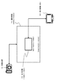
まず、図1を参照して本開示の処理を実行する撮像装置の構成例について説明する。
図1は、本開示の撮像装置10の外観を示す図である。図1(a)は、撮像装置10の正面図、図1(b)は背面図である。撮像装置10は、レンズ11、シャッタ12、表示部21、入力部22を有する。
[1. Configuration example of imaging device]
First, a configuration example of an imaging apparatus that executes the processing of the present disclosure will be described with reference to FIG.
FIG. 1 is a diagram illustrating an appearance of an
撮像部を構成するレンズ11を介して入射する被写体像は、表示部21に表示される。なお、本開示の処理を実行する撮像装置は、例えばデジタル一眼レフカメラ(DSLR:Digital Single Lens Reflex Camera)や、一般的なデジタルカメラであり、撮影対象とする被写体像を表示する表示部21を備え、ユーザ(撮影者)が表示部21に表示される画像を確認して撮影を行うことができる構成を持つ。 A subject image incident through the lens 11 constituting the imaging unit is displayed on the display unit 21. Note that an imaging apparatus that executes the processing of the present disclosure is, for example, a digital single lens reflex camera (DSLR) or a general digital camera, and includes a display unit 21 that displays a subject image to be captured. A user (photographer) can check the image displayed on the display unit 21 and perform shooting.
撮像装置10は、動画撮影や微速度(Time Lapse)撮影が可能な撮像装置である。前述したように、微速度撮影は間欠的に静止画を順次撮影する処理である。
以下の実施例では、微速度(Time Lapse)撮影を行う場合の例について説明する。ただし、以下において説明する処理は、微速度(Time Lapse)撮影に限らず、一般的な動画撮影にも適用可能である。
なお、以下に説明する本開示の処理を適用する場合、撮像装置は固定した状態で撮影することが好ましい。具体的には三脚などに固定した状態で撮影を行う。
The
In the following embodiment, an example in which time-lapse shooting is performed will be described. However, the processing described below is applicable not only to time lapse shooting but also to general moving image shooting.
In addition, when applying the process of this indication demonstrated below, it is preferable to image | photograph with an imaging device fixed. Specifically, shooting is performed with a tripod fixed.
表示部21は、レンズ11を介して入射する被写体画像の他、メモリに記録された撮影済みの画像の再生表示、さらに各種の操作情報やマニュアルなどの各種情報の表示に利用される。なお、表示部21は、タッチパネル機能を有した構成としてもよい。この場合、表示部21は、ユーザ操作情報を入力する入力部としても機能する。表示部21の表示情報の切り替えは、入力部22や表示部(入力部)21に対するユーザ操作によって行われる。 The display unit 21 is used for reproducing and displaying a photographed image recorded in a memory in addition to a subject image incident through the lens 11 and for displaying various operation information and various information such as a manual. The display unit 21 may have a configuration having a touch panel function. In this case, the display unit 21 also functions as an input unit for inputting user operation information. The display information on the display unit 21 is switched by a user operation on the input unit 22 or the display unit (input unit) 21.
本開示の処理を適用した微速度(Time Lapse)撮影を行う場合、ユーザ(撮影者)は、撮影開始前に表示部21に表示される画像内に開始フレームと、終了フレームの位置と大きさを指定することができる。
ユーザの指定する開始フレーム、終了フレームは、撮影画像から切り出して(トリミング)、フラッシュメモリ等の記憶部に格納する画像を生成するためのフレームの位置とサイズ情報として撮像装置内のメモリに格納される。
When performing time lapse shooting using the processing of the present disclosure, the user (photographer) positions and sizes of the start frame and the end frame in the image displayed on the display unit 21 before the start of shooting. Can be specified.
The start frame and end frame specified by the user are cut out from the captured image (trimming) and stored in the memory in the imaging apparatus as frame position and size information for generating an image to be stored in a storage unit such as a flash memory. The
ユーザは、撮影開始前に、例えばカメラを三脚等に固定して撮像装置を被写体の方向に向けて固定し、表示部21にレンズ11を介して入射する被写体像、いわゆるスルー画を表示させる。ユーザは、表示部21に表示される画像(スルー画)内に撮影開始画像フレームと、撮影終了画像フレームの位置と大きさを指定する。 Prior to the start of shooting, for example, the camera is fixed on a tripod or the like, the imaging apparatus is fixed in the direction of the subject, and a subject image incident through the lens 11, a so-called through image, is displayed on the display unit 21. The user designates the position and size of the shooting start image frame and the shooting end image frame in the image (through image) displayed on the display unit 21.
これらの開始点、終了点の2つの画像フレームの指定を行って撮影を開始することで、指定した撮影開始画像フレームを起点とし、撮影終了画像フレームを終点とした複数の静止画像が記録される。
この具体的な処理については、後段で詳細に説明する。
By specifying these two start and end image frames and starting shooting, a plurality of still images are recorded starting from the specified shooting start image frame and ending at the shooting end image frame. .
This specific processing will be described in detail later.
[2.撮影画像の表示処理例について]
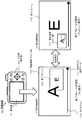
次に、図2を参照して撮像装置10の撮影画像を表示する場合の画像表示例について説明する。
図2(A)に示すように、撮像装置10による撮影画像は記憶部としての記録メディア51に格納される。記録メディア51に格納された画像は、再生表示が可能であり、例えば、図2に示すようなHD(High Definition)画像を表示可能なテレビ等の表示装置50に出力され表示される。
[2. About display processing example of shot image]
Next, an image display example when displaying a captured image of the
As shown in FIG. 2A, an image captured by the
なお、表示装置50に撮影画像を表示する場合は、記録メディア51を撮像装置10から取り出して、表示装置50に装着する。あるいは、信号伝送ケーブル52を介して撮像装置10から表示装置50に画像を転送する。あるいは、無線通信路53を介して撮像装置10から表示装置50に画像を転送する。これらいずれかの処理を実行する。
When displaying a captured image on the display device 50, the
昨今の撮像装置10の撮像素子は高画素化が進み、例えば図2(B)に示すように、横画素数×縦画素数≒6000×4000の画素数を有する。これに対して、HD画像を表示可能なHDTVである表示装置50は、横画素数×縦画素数≒1920×1080の画素数である。
このように、最近の一般的なデジタルカメラに利用されている撮像素子の画素数はHDTV等の一般的なハイビジョン画像表示装置の画素数よりはるかに多い設定となっている。
2. Description of the Related Art The recent increase in the number of pixels in the image pickup device of the
As described above, the number of pixels of an image sensor used in a recent general digital camera is set to be much larger than the number of pixels of a general high-definition image display device such as an HDTV.
従って、撮像装置の撮影画像全体をそのままの画素数でHDTV等の表示装置に表示することはできず、画素の間引き処理を実行して6000×4000の画素数を削減し、1920×1080の画素数を持つ表示用画像を生成して出力することが必要となる。
これは、言い換えると、高画素数を持つ撮像素子を有する撮像装置10の撮影画像の一部領域を切り出して表示装置50に出力しても高画質なHD画像の表示が可能であることを意味する。
Therefore, the entire captured image of the image pickup device cannot be displayed on a display device such as an HDTV with the same number of pixels, and the pixel thinning process is executed to reduce the number of pixels of 6000 × 4000, and 1920 × 1080 pixels. It is necessary to generate and output a display image having a number.
In other words, this means that a high-quality HD image can be displayed even if a partial region of a captured image of the
すなわち、図3に示すように、撮像装置10の撮影画像71は6000×4000画素の画素数を持つ。この撮影画像71の一部の画素領域(1920×1080画素)の切り出し処理(トリミング)を行って表示装置50に表示する出力画像72とする。図3に示す例では、出力画像は、1920×1080画素の画素数を有する。すなわちHD画像に相当する画素数を持つ。
That is, as shown in FIG. 3, the captured image 71 of the
このように、撮影画像の一部領域を切り出して、切り出し領域を出力画像72として設定しても、表示装置50では画質を低下させることなくHD画像として出力表示することが可能となる。
なお、図3に示す出力画像72の設定例は、HD画像としての出力に必要となる画像切り出しの一例であり、この他にも様々な画像切り出し領域の設定が可能である。
As described above, even if a partial area of the captured image is cut out and the cut-out area is set as the output image 72, the display device 50 can output and display it as an HD image without reducing the image quality.
Note that the setting example of the output image 72 shown in FIG. 3 is an example of image clipping required for output as an HD image, and various other image clipping regions can be set.
図4は、撮影画像と出力表示画像の設定例を示す図である。
点線の矩形領域が撮影画像であり、6000×4000の構成画素を有する。一方実線の矩形領域が、表示装置に対する出力表示画像の画素領域である。
図4(A)は、図3において説明したと同様の設定例であり、撮影画像のほぼ中央部に1920×1080画素の出力画像の切り出し領域を設定した例である。
FIG. 4 is a diagram illustrating a setting example of a captured image and an output display image.
A dotted-line rectangular area is a captured image, and has 6000 × 4000 constituent pixels. On the other hand, the solid rectangular region is the pixel region of the output display image for the display device.
FIG. 4A is a setting example similar to that described with reference to FIG. 3, and is an example in which a cut-out region of an output image of 1920 × 1080 pixels is set in the substantially central portion of the photographed image.
図4(B)は、撮影画像の左上部に1920×1080画素の出力画像の切り出し領域を設定した例である。
図4(C)は、撮影画像の右下部に3840×2160画素の出力画像の切り出し領域を設定した例である。
図4(D)は、撮影画像の右下部に5760×3240画素の出力画像の切り出し領域を設定した例である。
FIG. 4B shows an example in which an output image cut-out area of 1920 × 1080 pixels is set in the upper left part of the captured image.
FIG. 4C illustrates an example in which a 3840 × 2160 pixel output image clipping region is set in the lower right portion of the captured image.
FIG. 4D shows an example in which a cut-out area of an output image of 5760 × 3240 pixels is set in the lower right part of the captured image.
なお、図4(C),(D)の切り出し領域は、HD画像の画素数より多いため、HD画像表示装置に出力する場合は、画素数を削減して出力する処理が必要となる。しかし、この場合もオリジナル画像の画素数はHD画像の画素数以上を有する画像であり、画素数削減によって得られる出力画像はHD画像としての画質を有する画像となる。 4C and 4D has a larger number of cutout areas than the number of pixels of the HD image. Therefore, when outputting to the HD image display device, it is necessary to reduce and output the number of pixels. However, in this case as well, the number of pixels of the original image is an image having more than the number of pixels of the HD image, and the output image obtained by reducing the number of pixels is an image having the image quality as an HD image.
このように、撮影画像の一部領域を切り出して表示装置に出力、あるいはメモリに記録する処理を行なっても、少なくともHD画像に相当する画質を有する画像表示や画像記録処理が可能となる。 As described above, even when a process of cutting out a partial area of a captured image and outputting it to a display device or recording it in a memory, an image display or image recording process having an image quality equivalent to at least an HD image can be performed.
[3.本開示の画像撮影処理シーケンスについて]
次に、本開示の撮像装置における画像撮影処理シーケンスについて図5に示すフローチャートを参照して説明する。
[3. Regarding Image Shooting Processing Sequence of Present Disclosure]
Next, an image capturing process sequence in the imaging apparatus according to the present disclosure will be described with reference to a flowchart illustrated in FIG.
図5に示すフローチャートは、微速度撮影を行う場合の各種の設定情報、すなわち画像撮影処理や記録処理に適用するパラメータの設定から撮影開始までの処理手順を説明するフローである。
例えば撮像装置の制御部の制御の下、このフローに従った設定情報が撮像装置のメモリに記録される。さらに、画像撮影処理の実行時には、撮像装置の制御部が、メモリに格納された設定情報を読み出し、設定情報に従った画像撮影や画像記録処理を実行する。
The flowchart shown in FIG. 5 is a flowchart for explaining various setting information when performing time-lapse shooting, that is, a processing procedure from setting of parameters applied to image shooting processing and recording processing to shooting start.
For example, setting information according to this flow is recorded in the memory of the imaging device under the control of the control unit of the imaging device. Further, when executing the image capturing process, the control unit of the imaging apparatus reads the setting information stored in the memory, and executes image capturing and image recording processing according to the setting information.
以下、図5に示すフローの各ステップの処理について、順次説明する。
(ステップS101)
まず、ユーザ(撮影者)は、撮影モードを選択する。なお、本実施例では、撮影モードとして微速度(Time Lapse)撮影を選択した例について説明する。
ステップS101では、撮影モードとして微速度撮影モードを選択する。なお、このステップS101以下において実行される各種情報の設定処理は、図1に示す撮像装置10の入力部22を介したユーザ操作によって実行される。表示部21がタッチパネル形式を有する場合は、表示部(入力部)21に対するユーザ操作によって行うことも可能である。
Hereinafter, the process of each step of the flow shown in FIG. 5 will be described sequentially.
(Step S101)
First, the user (photographer) selects a shooting mode. In this embodiment, an example in which time lapse shooting is selected as the shooting mode will be described.
In step S101, the time-lapse shooting mode is selected as the shooting mode. It should be noted that the various information setting processing executed in step S101 and subsequent steps is executed by a user operation via the input unit 22 of the
(ステップS102〜S103)
次に、ユーザは、ステップS102において撮影期間を設定し、ステップS103において撮影枚数を設定する。
撮影期間の設定とは、微速度撮影の撮影開始から撮影終了までの時間の設定である。
撮影枚数の設定とは、設定した撮影期間内に何枚の画像を撮影するかを設定する処理である。
(Steps S102 to S103)
Next, the user sets a shooting period in step S102, and sets the number of shots in step S103.
The setting of the shooting period is the setting of the time from the start of shooting of the time-lapse shooting to the end of shooting.
The setting of the number of shots is a process of setting how many images are shot within a set shooting period.
例えば撮影期間を4時間に設定し、撮影枚数を240枚に設定する等の処理を行なう。
撮影期間=4時間、
撮影枚数=240枚、
例えば上記の設定を行い、各画像フレームの撮影間隔が等しい場合、1時間あたり約60枚の撮影が行われることになり、ほぼ1分単位で1枚の画像撮影が実行されることになる。
For example, processing such as setting the shooting period to 4 hours and setting the number of shots to 240 is performed.
Shooting period = 4 hours,
Number of shots = 240,
For example, when the above setting is performed and the shooting intervals of the respective image frames are equal, about 60 shots are taken per hour, and one image is shot almost every minute.
(ステップS104)
次に、ユーザ(撮像装置)は、撮像装置を被写体方向にレンズを向けて固定して、レンズを介して入射する画像を表示部に表示させる。いわゆるスルー画を表示部に表示させる。
(Step S104)
Next, the user (imaging device) fixes the imaging device with the lens facing the subject and displays an image incident through the lens on the display unit. A so-called through image is displayed on the display unit.
(ステップS105)
次に、ユーザ(撮像装置)は、表示部に表示されたスルー画を参照してフレーム設定情報を入力する。
ステップS105〜S108において、ユーザは微速度撮影や動画撮影において撮影、記録する複数の画像フレームに関する画像切り出し位置等を決定するための様々なフレーム設定情報を入力する。
まず、ステップS105では、微速度撮影において最初に撮影する画像、すなわち開始フレームの位置とサイズを設定する。
(Step S105)
Next, the user (imaging device) inputs frame setting information with reference to the through image displayed on the display unit.
In steps S <b> 105 to S <b> 108, the user inputs various frame setting information for determining image cutout positions and the like regarding a plurality of image frames to be shot and recorded in time-lapse shooting and moving image shooting.
First, in step S105, the first image to be taken in time-lapse photography, that is, the position and size of the start frame are set.
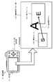
このステップS105の処理の具体例について図6を参照して説明する。
図6(1)表示画面例1は、開始フレームの設定処理時の表示部21の表示画像例を示す図である。
A specific example of the process in step S105 will be described with reference to FIG.
FIG. 6A is a diagram illustrating a display image example of the display unit 21 during the start frame setting process.
表示部21全体には、撮像装置10がレンズを介して入射している現時点の撮影画像(スルー画)101が表示されている。図に示す文字Aの表示画像が現時点の撮影画像(スルー画)101である。
On the entire display unit 21, a current captured image (through image) 101 on which the
撮影画像(スルー画)101の下部に示す一本のラインは、タイムライン110である。タイムライン110の左端の黒丸は設定タイム指示マーク111である。
タイムライン110は、左端が微速度撮影の撮影開始時間に対応し、右端が撮影終了時間に相当する時間軸を示したラインである。
図6(1)の例では、設定タイム指示マーク111が左端に示されているので、現在の表示画面が微速度撮影の撮影開始時間の撮影画像の設定を行う画面であることを示している。
One line shown at the bottom of the captured image (through image) 101 is a timeline 110. The black circle at the left end of the timeline 110 is a set time instruction mark 111.
In the timeline 110, the left end corresponds to the shooting start time of the time-lapse shooting, and the right end represents a time axis corresponding to the shooting end time.
In the example of FIG. 6A, since the set time instruction mark 111 is shown at the left end, it indicates that the current display screen is a screen for setting a shot image at the shooting start time of the time-lapse shooting. .
なお、ユーザは、入力部の操作によって、設定タイム指示マーク111をタイムライン110上で自由に移動可能であり、設定タイム指示マーク111を任意の位置に設定した上で、その時間における撮影画像フレームの位置とサイズを設定できる。 Note that the user can freely move the set time instruction mark 111 on the timeline 110 by operating the input unit, set the set time instruction mark 111 at an arbitrary position, and then the captured image frame at that time. You can set the position and size.
図6(1)に示す例は、設定タイム指示マーク111を左端に設定した例であり、微速度撮影の開始時間の画像フレーム、すなわち、図に示す開始フレーム(S)102の設定を行う画面である。図に示す文字Sが表示された矩形枠が開始フレーム(S)102である。図に示す例は、左下の位置に開始フレーム(S)102を設定した例である。開始フレーム(S)102は、例えば1920×1080画素以上の画素数を持つ設定とすることが好ましい。すなわち、少なくとも表示装置の表示可能な画素数以上、例えば図2に示す表示装置50の表示可能なHD画像に相当する画素数以上の画素数を持つ設定とすることが好ましい。 The example shown in FIG. 6 (1) is an example in which the set time instruction mark 111 is set at the left end, and a screen for setting the image frame of the time-lapse shooting start time, that is, the start frame (S) 102 shown in the figure. It is. A rectangular frame in which the character S shown in the figure is displayed is a start frame (S) 102. The example shown in the figure is an example in which the start frame (S) 102 is set at the lower left position. The start frame (S) 102 is preferably set to have a pixel number of, for example, 1920 × 1080 pixels or more. That is, it is preferable to set the number of pixels at least equal to or greater than the number of pixels that can be displayed on the display device, for example, equal to or greater than the number of pixels corresponding to the HD image that can be displayed on the display device 50 shown in FIG.
ユーザは、撮影画像(スルー画)101上の任意の位置に、開始フレーム(S)の画像位置を決定するとともに、開始フレーム(S)のフレームサイズを決定することができる。 The user can determine the image position of the start frame (S) at an arbitrary position on the captured image (through image) 101 and the frame size of the start frame (S).
開始フレームの設定シーケンスの一例について図7を参照して説明する。図7の上段の(S21:初期画面)は、開始フレーム設定時の初期画面の例である。初期画面は、(S21)に示すように、撮影画像(スルー画)101上に、例えば1920×1080画素の開始フレーム102が初期設定として表示された画像である。 An example of a start frame setting sequence will be described with reference to FIG. The upper part of FIG. 7 (S21: initial screen) is an example of the initial screen when the start frame is set. As shown in (S21), the initial screen is an image in which a start frame 102 of, for example, 1920 × 1080 pixels is displayed as an initial setting on a captured image (through image) 101.
ユーザは、この初期設定の開始フレーム102を指定して任意の位置に移動させる。例えば、図7(S22:位置決定処理)に示すように、カーソル(指示子)105によって開始フレーム102を指定して移動させる。 The user designates the initial start frame 102 and moves it to an arbitrary position. For example, as shown in FIG. 7 (S22: position determination process), the start frame 102 is designated and moved by a cursor (indicator) 105.
この移動処理によって、開始フレーム102の位置を決定し、さらに、図7(S23:サイズ決定処理)に示すように、開始フレーム102の矩形枠の大きさを変更して、サイズを決定する。この処理は、例えば入力部22のスイッチやジョグダイヤルの操作によって行うことができる。あるいは、タッチパネル型の表示部21である場合は、指で開始フレーム102の矩形枠を拡縮させる動作によってサイズ変更を可能な構成としてもよい。 By this movement process, the position of the start frame 102 is determined, and further, as shown in FIG. 7 (S23: size determination process), the size of the rectangular frame of the start frame 102 is changed to determine the size. This process can be performed, for example, by operating a switch of the input unit 22 or a jog dial. Alternatively, in the case of the touch panel type display unit 21, the size may be changed by an operation of expanding or reducing the rectangular frame of the start frame 102 with a finger.
ユーザは、例えば図7に示す処理シーケンスに従って開始フレームの位置とサイズを決定する。なお、図7では、開始フレームの位置とサイズの決定のための操作方法として、カーソルや操作部のジョグダイヤルやスイッチ、あるいはタッチパネルを適用した操作方法を説明したが、これは一例である。操作方法は、撮像装置の入力部の構成に従って決定され、操作部構成に応じた様々な操作手法を適用して開始フレームの位置とサイズの決定を行うことが可能である。 For example, the user determines the position and size of the start frame in accordance with the processing sequence shown in FIG. In FIG. 7, an operation method using a cursor, a jog dial or switch of an operation unit, or a touch panel is described as an operation method for determining the position and size of the start frame, but this is only an example. The operation method is determined according to the configuration of the input unit of the imaging apparatus, and the position and size of the start frame can be determined by applying various operation methods according to the configuration of the operation unit.
図6(1)表示画面例1は、開始フレーム102の位置とサイズを決定した時点の表示部の表示画像の一例である。この図6(1)の表示画像は、撮影画像(スルー画)101を全画面表示し、その一部の領域が開始フレーム102の表示位置となっている。ユーザは、さらに、図6(2)表示画面例2に示すように、開始フレーム102の画像を表示部の表示領域全体を用いて表示し、スルー画に対する開始フレームの位置関係を示す画像を子画面として示す画像を表示可能である。
ユーザは図6(1),(2)に示す2つの画像の切り替えを行うことができる。この切り替え処理は、入力部22を適用したユーザ操作によって実行される。
FIG. 6 (1) display screen example 1 is an example of a display image on the display unit when the position and size of the start frame 102 are determined. In the display image of FIG. 6 (1), the captured image (through image) 101 is displayed on the full screen, and a part of the region is the display position of the start frame 102. The user further displays the image of the start frame 102 using the entire display area of the display unit as shown in FIG. 6 (2) display screen example 2, and displays an image indicating the positional relationship of the start frame with respect to the through image. An image shown as a screen can be displayed.
The user can switch between the two images shown in FIGS. 6 (1) and (2). This switching process is executed by a user operation to which the input unit 22 is applied.
(ステップS106)
ステップS105において、開始フレームの位置とサイズを決定した後、次に、ユーザ(撮像装置)は、表示部に表示されたスルー画を参照して新たなフレーム設定情報を入力する。具体的には、微速度撮影において最後に撮影する画像、すなわち終了フレームの位置とサイズを設定する。
(Step S106)
In step S105, after determining the position and size of the start frame, the user (imaging device) then inputs new frame setting information with reference to the through image displayed on the display unit. Specifically, the position and size of the last image to be taken in time-lapse photography, that is, the end frame is set.
このステップS106の処理の具体例について図8を参照して説明する。
図8(1)表示画面例1は、終了フレームの設定処理時の表示部21の表示画像例を示す図である。
表示部21全体には、撮像装置10がレンズを介して入射している現時点の撮影画像(スルー画)101が表示されている。図に示す文字Aの表示画像が現時点の撮影画像(スルー画)101である。
A specific example of the processing in step S106 will be described with reference to FIG.
FIG. 8A is a diagram illustrating a display image example 1 of the display unit 21 during the end frame setting process.
On the entire display unit 21, a current captured image (through image) 101 on which the
撮影画像(スルー画)101の下部に示す一本のラインは、タイムライン110である。タイムライン110の右端の黒丸は設定タイム指示マーク111である。
前述したように、タイムライン110は、左端が微速度撮影の開始時間に対応し、右端が終了時間に相当する時間軸を示したラインである。
One line shown at the bottom of the captured image (through image) 101 is a timeline 110. A black circle at the right end of the timeline 110 is a set time instruction mark 111.
As described above, in the time line 110, the left end corresponds to the start time of the time-lapse shooting, and the right end is a line indicating the time axis corresponding to the end time.
図8(1)は、設定タイム指示マーク111を右端に設定し、微速度撮影の終了時間の画像フレーム、すなわち、図に示す終了フレーム(E)103の設定を行う場合の例を示している。図に示す文字Eが表示された矩形枠が終了フレーム(E)103である。この例では、右下の位置に終了フレーム(E)103を設定した例を示している。終了フレーム(E)103は、例えば1920×1080画素以上の画素数を持つ設定とすることが好ましい。すなわち、少なくとも表示装置の表示可能な画素数以上、例えば図2に示す表示装置50の表示可能なHD画像に相当する画素数以上の画素数を持つ設定とすることが好ましい。 FIG. 8A shows an example in which the set time instruction mark 111 is set at the right end and the image frame of the time-lapse shooting end time, that is, the end frame (E) 103 shown in FIG. 8 is set. . A rectangular frame in which a character E shown in the figure is displayed is an end frame (E) 103. In this example, an end frame (E) 103 is set at the lower right position. The end frame (E) 103 is preferably set to have a pixel number of, for example, 1920 × 1080 pixels or more. That is, it is preferable to set the number of pixels at least equal to or greater than the number of pixels that can be displayed on the display device, for example, equal to or greater than the number of pixels corresponding to the HD image that can be displayed on the display device 50 shown in FIG.
ユーザは、撮影画像(スルー画)101上の任意の位置に、終了フレームの画像位置を決定し、任意のフレームサイズを決定することができる。 The user can determine the image position of the end frame at an arbitrary position on the captured image (through image) 101 and determine an arbitrary frame size.
終了フレームの設定シーケンスは、先に図7を参照して説明した開始フレームの設定シーケンスと同様のシーケンスとなる。図7に示す開始フレーム(S)102を終了フレーム(E)に置き換えた処理となる。
終了フレーム(E)設定時の初期画面は、図7の上段の(S21:初期画面)に示すように、撮影画像(スルー画)101上に、例えば1920×1080画素の終了フレーム(E)を表示した画面である。
The end frame setting sequence is similar to the start frame setting sequence described above with reference to FIG. This is a process in which the start frame (S) 102 shown in FIG. 7 is replaced with the end frame (E).
The initial screen when the end frame (E) is set is, for example, an end frame (E) of 1920 × 1080 pixels, for example, on the photographed image (through image) 101, as shown in the upper part of FIG. 7 (S21: initial screen). This is the displayed screen.
ユーザは、表示された終了フレーム(E)を指定して任意の位置に移動させる。図7(S22:位置決定処理)に示すように、カーソル(指示子)105によって終了フレーム(E)を移動させる。この移動処理によって、終了フレーム(E)の位置を決定し、さらに、図7(S23:サイズ決定処理)に示すように、終了フレーム(E)の矩形枠の大きさを変更して、サイズを決定する。 The user designates the displayed end frame (E) and moves it to an arbitrary position. As shown in FIG. 7 (S22: position determination process), the end frame (E) is moved by the cursor (indicator) 105. By this movement process, the position of the end frame (E) is determined. Further, as shown in FIG. 7 (S23: size determination process), the size of the rectangular frame of the end frame (E) is changed to change the size. decide.
図8(1)表示画面例1は、終了フレーム103の位置とサイズを決定した時点の表示部の表示画像の一例である。この図8(1)の表示画像は、撮影画像(スルー画)101を全画面表示し、その一部の領域が終了フレーム103の表示位置となっている。ユーザは、さらに、図8(2)表示画面例2に示すように、終了フレーム103の画像を表示部の表示領域全体を用いて表示し、スルー画に対する終了フレームの位置関係を示す画像を子画面として示す画像切り替えを行うことができる。この切り替え処理は、入力部22を適用したユーザ操作によって実行される。 FIG. 8A shows a display screen example 1 which is an example of a display image on the display unit at the time when the position and size of the end frame 103 are determined. In the display image of FIG. 8 (1), the captured image (through image) 101 is displayed on the full screen, and a partial area thereof is the display position of the end frame 103. The user further displays the image of the end frame 103 using the entire display area of the display unit as shown in FIG. 8 (2) display screen example 2, and displays an image indicating the positional relationship of the end frame with respect to the through image. Image switching shown as a screen can be performed. This switching process is executed by a user operation to which the input unit 22 is applied.
このように、ユーザは、撮像装置10の表示部21にレンズを介して撮り込まれるスルー画を表示しながら、微速度撮影や動画撮影時の最初の撮影画像(開始フレーム)と最後の撮影画像(終了フレーム)の各画像フレームの位置とサイズを決定することができる。
In this way, the user displays the first captured image (start frame) and the last captured image during time-lapse shooting or movie shooting while displaying a through image captured through the lens on the display unit 21 of the
(ステップS107)
次に、図5に示すフローのステップS107において、ステップS105で設定した開始フレームからステップS106で設定した終了フレームまでの撮影画像の軌跡を設定する。
軌跡は、微速度撮影において開始フレームから終了フレームまでの間に撮影する中間フレームの位置とサイズを決定するための情報として利用される。
(Step S107)
Next, in step S107 of the flow shown in FIG. 5, the trajectory of the captured image from the start frame set in step S105 to the end frame set in step S106 is set.
The trajectory is used as information for determining the position and size of an intermediate frame that is captured between the start frame and the end frame in time-lapse imaging.
このステップS107の軌跡設定処理の具体例について、図9、図10を参照して説明する。
図9(1)表示画面例は、軌跡設定処理時の撮像装置10の表示部21の表示画面の一例を示した図である。
A specific example of the trajectory setting process in step S107 will be described with reference to FIGS.
FIG. 9 (1) is a diagram showing an example of the display screen of the display unit 21 of the
ステップS107の軌跡設定処理の開始時点で撮像装置10の表示部21には撮像装置のレンズを介して撮り込まれている撮影画像(スルー画)101が表示され、さらに、ステップS105、S106において設定した開始フレーム(S)102と終了フレーム(E)103の設定枠が表示される。
A captured image (through image) 101 captured through the lens of the imaging apparatus is displayed on the display unit 21 of the
ステップS107では、この2つのフレームを接続する線を軌跡設定ライン120として設定する。
図9に示す軌跡設定ラインは、一例として直線の軌跡を設定した例を示しているが、軌跡は直線に限らず、曲線、折れ線など様々な設定が可能である。
In step S107, a line connecting these two frames is set as a trajectory setting line 120.
The trajectory setting line shown in FIG. 9 shows an example in which a straight trajectory is set as an example, but the trajectory is not limited to a straight line, and various settings such as a curve and a broken line are possible.
図10は、軌跡設定時の表示部21の画面例を示した図である。(S31:初期画面)が、軌跡設定時の表示部21の初期画面例である。
撮像装置10の表示部21には、スルー画に対して設定済みの開始フレーム(S)と終了フレーム(E)の矩形枠を表示した画像表示領域に加え、軌跡設定アイコン121が表示される。
FIG. 10 is a diagram illustrating a screen example of the display unit 21 when setting a trajectory. (S31: initial screen) is an example of the initial screen of the display unit 21 when the locus is set.
On the display unit 21 of the
軌跡設定アイコン121には、開始フレーム(S)から終了フレーム(E)までの軌跡の設定のために選択可能な軌跡ラインのサンプルが複数、示されている。ユーザは、これらのサンプルからいずれかを選択して、軌跡を設定することができる。
図10(S32:軌跡設定後画面)は、ユーザが折れ線の軌跡を選択して決定した例を示している。
図に示すように、開始フレーム(S)から終了フレーム(E)を結ぶ折れ線ラインが、軌跡設定ライン120として表示される。
The trajectory setting icon 121 shows a plurality of trajectory line samples that can be selected for setting the trajectory from the start frame (S) to the end frame (E). The user can select one of these samples and set the trajectory.
FIG. 10 (S32: screen after trajectory setting) shows an example in which the user selects and determines a trajectory of a broken line.
As shown in the figure, a polygonal line connecting the start frame (S) to the end frame (E) is displayed as the trajectory setting line 120.
微速度撮影や動画像の撮影記録処理が開始されると、撮像装置の制御部の制御に従って、ユーザの設定した軌跡に沿った画像を記録画像としてメモリに順次記録する処理が行われる。 When time-lapse shooting or moving image shooting / recording processing is started, under the control of the control unit of the imaging apparatus, processing is performed in which images along the locus set by the user are sequentially recorded in the memory as recorded images.
(ステップS108)
次に、図5に示すフローのステップS108において、ステップS107で設定した開始フレーム(S)から終了フレーム(E)までの軌跡に従って順次撮影する画像の遷移スピードに相当する移動スピードを設定する。
移動スピードも、軌跡と同様、微速度撮影において開始フレームから終了フレームまでの間に撮影する中間フレームの位置とサイズを決定するための情報として利用される。
(Step S108)
Next, in step S108 of the flow shown in FIG. 5, a moving speed corresponding to the transition speed of images that are sequentially photographed is set according to the trajectory from the start frame (S) to the end frame (E) set in step S107.
Similar to the trajectory, the moving speed is also used as information for determining the position and size of an intermediate frame to be captured between the start frame and the end frame in time-lapse shooting.
このステップS108の移動スピード設定処理の具体例について、図11を参照して説明する。
図11(1)表示画面例は、移動スピード設定処理時の撮像装置10の表示部21の表示画面の一例を示した図である。
A specific example of the movement speed setting process in step S108 will be described with reference to FIG.
FIG. 11 (1) is a diagram showing an example of the display screen of the display unit 21 of the
ステップS108の移動スピード設定処理の開始時点で撮像装置10の表示部21には撮像装置のレンズを介して撮り込まれている撮影画像(スルー画)101が表示され、さらに、ステップS105、S106において設定した開始フレーム(S)102と終了フレーム(E)103の設定枠と、ステップS107において設定した開始フレーム(S)102と終了フレーム(E)103間を結ぶ軌跡設定ラインが表示されている。
A captured image (through image) 101 captured through the lens of the imaging device is displayed on the display unit 21 of the
ステップS108では、開始、終了フレームを接続する軌跡設定ラインを移動スピード設定ライン130に変更する処理を行なう。
移動スピード設定ラインは、開始フレーム(S)102から、終了フレーム(E)までの間に撮影される複数の画像フレームの移動スピードを設定するためのラインである。
In step S108, a process of changing the trajectory setting line connecting the start and end frames to the movement speed setting line 130 is performed.
The moving speed setting line is a line for setting moving speeds of a plurality of image frames photographed between the start frame (S) 102 and the end frame (E).
例えば図11に示す移動スピード設定ライン130は、開始フレーム(S)102から終了フレーム(E)103を結ぶ点線として表示されているが、線の長さが開始フレーム(S)102側で長く、終了フレーム(E)103側で短く設定されている。 For example, the moving speed setting line 130 shown in FIG. 11 is displayed as a dotted line connecting the start frame (S) 102 to the end frame (E) 103, but the length of the line is longer on the start frame (S) 102 side. It is set shorter on the end frame (E) 103 side.
線の長い点線は、移動スピードが遅く、線の短い点線は、移動スピードが速いことを示している。
すなわち、図11に示す移動スピード設定ライン130は、開始フレーム(S)102から、終了フレーム(E)までの間に所定時間間隔で順次撮影される複数の画像フレームの移動スピードを以下のような設定としたことを意味する。
A long dotted line indicates that the moving speed is slow, and a short dotted line indicates that the moving speed is high.
That is, the moving speed setting line 130 shown in FIG. 11 indicates the moving speed of a plurality of image frames that are sequentially photographed at predetermined time intervals from the start frame (S) 102 to the end frame (E) as follows. It means that it was set.
開始フレーム(S)撮影直後の移動スピードは低速とする。
すなわち、開始フレーム(S)102からの移動距離を小さくして次の画像フレームの撮影を実行する。
その後、次第に移動スピードを上げていき、終了フレーム(E)103の撮影に近づくに従って移動スピードを高速とした撮影を実行する。
すなわち、例えば終了フレーム(E)103とその前の撮影画像フレームの移動距離を大きく設定して撮影処理を実行する。
The moving speed immediately after the start frame (S) is shot is low.
That is, the moving distance from the start frame (S) 102 is shortened to capture the next image frame.
Thereafter, the moving speed is gradually increased, and shooting at a higher moving speed is performed as the end frame (E) 103 is approached.
That is, for example, the shooting process is executed by setting a large moving distance between the end frame (E) 103 and the previous captured image frame.
このように所定間隔で撮影される各画像フレーム位置の移動スピードの設定を行う。このような設定を行う。移動スピードの設定により、各画像フレームの撮影時間間隔を一定としても、その一定の撮影間隔の間に移動するフレーム間距離を異なる設定とすることが可能となる。 In this way, the moving speed of each image frame position photographed at a predetermined interval is set. Such setting is performed. Even if the shooting time interval of each image frame is fixed by setting the moving speed, it is possible to set different distances between frames that move during the fixed shooting interval.
図11に示す移動スピード設定ライン130を設定した場合の各撮影フレームと移動スピードとの対応関係の具体例について、図12を参照して説明する。
図12(1)は、図11に示す移動スピード設定ライン130を設定した場合の移動スピードとフレームとの対応関係を示すグラフである。横軸にフレーム、縦軸に移動スピードを示している。
横軸は、左端を開始フレーム(S)として、右方向に順次、撮影フレームが進行して終了フレーム(E)に至るラインである。
縦軸は、下側が低速であり、上方向が高速であることを示す。
A specific example of the correspondence relationship between each captured frame and the moving speed when the moving speed setting line 130 shown in FIG. 11 is set will be described with reference to FIG.
FIG. 12A is a graph showing the correspondence between the movement speed and the frame when the movement speed setting line 130 shown in FIG. 11 is set. The horizontal axis indicates the frame, and the vertical axis indicates the moving speed.
The horizontal axis is a line where the left end is the start frame (S), and the shooting frame advances sequentially to the end frame (E) in the right direction.
The vertical axis indicates that the lower side is low speed and the upper direction is high speed.
先に説明したように、開始フレーム(S)撮影直後の移動スピードは低速であり、その後、移動スピードを上げていき、終了フレーム(E)の撮影に近づくと最高速となる。 As described above, the moving speed immediately after the start frame (S) is shot is low, and thereafter, the moving speed is increased, and the maximum speed is reached when the end frame (E) is approached.
図12(2)は、開始フレーム(S)から終了フレーム(E)までに撮影される画像フレームの位置とサイズについて示す図である。
図12に示す例は、開始フレームから終了フレームまで40フレームを撮影する設定とした例であり、開始フレーム(S=F1)102を左下の小さい矩形領域に設定し、終了フレーム(E=F40)を右上のやや大きめの矩形領域に設定している。
移動スピードは、図11、図12(1)で示したと同様、開始フレーム(S)撮影直後の移動スピードは低速であり、その後、移動スピードを上げていき、終了フレーム(E)の撮影に近づくと最高速となる設定である。
FIG. 12 (2) is a diagram showing the position and size of image frames taken from the start frame (S) to the end frame (E).
The example shown in FIG. 12 is an example in which 40 frames are captured from the start frame to the end frame. The start frame (S = F1) 102 is set in a small rectangular area at the lower left, and the end frame (E = F40). Is set to a slightly larger rectangular area in the upper right.
The movement speed is the same as shown in FIGS. 11 and 12 (1). The movement speed immediately after the start frame (S) is shot is low, and then the movement speed is increased to approach the end frame (E). It is the setting which becomes the highest speed.
この移動スピードの設定では、開始フレーム(S=F1)の直後に撮影されるフレーム2(F2)やフレーム3(F3)のフレーム間移動距離は小さくなる。図に示すように、(F1)〜F2〜F3の各フレーム位置の間隔は小さく設定される。これは移動スピートを低速の設定としているからである。 With this movement speed setting, the inter-frame movement distance of frame 2 (F2) and frame 3 (F3) photographed immediately after the start frame (S = F1) becomes small. As shown in the figure, the interval between the frame positions (F1) to F2 to F3 is set small. This is because the moving speed is set to a low speed.
その後、移動スピードは次第に高速となり、各フレームの間隔は次第に大きくなる。最終的な撮影画像である終了フレーム(E=F40)とその直前に撮影するフレーム39(F39)や、さらにその前のフレーム38(F38)等の各画像フレームの間隔は大きくなる。これは、移動スピードが高速に設定されているためである。 Thereafter, the moving speed gradually increases and the interval between the frames gradually increases. The interval between the image frames, such as the final frame (E = F40) that is the final captured image, the frame 39 (F39) that is captured immediately before it, and the previous frame 38 (F38), becomes large. This is because the moving speed is set to a high speed.
なお、各画像フレームのサイズは、図に示すように開始フレーム(S)102のサイズから終了フレーム(E)103のサイズの間のサイズに設定され、開始フレームと終了フレームからの距離に応じて決定されるサイズとなる。 Note that the size of each image frame is set to a size between the size of the start frame (S) 102 and the size of the end frame (E) 103 as shown in the figure, and depends on the distance from the start frame to the end frame. The size is determined.
図に示すように、開始フレーム(S)102と終了フレーム(E)103との離間距離をL(E−S)とし、開始フレーム(S)102のサイズをS(size)、終了フレーム(E)103のサイズをE(size)する。
このとき、例えば、開始フレーム(S)102から距離L(F3−S)、離間した位置に設定される第3フレーム(F3)のサイズ[F3(size)]は、以下の算出式によって決定される。
F3(size)=S(size)+((E(size)−S(size))*(L(F3−S)/L((E−S))
As shown in the figure, the separation distance between the start frame (S) 102 and the end frame (E) 103 is L (ES), the size of the start frame (S) 102 is S (size), and the end frame (E ) E (size) the size of 103.
At this time, for example, the size [F3 (size)] of the third frame (F3) set at a position separated from the start frame (S) 102 by a distance L (F3-S) is determined by the following calculation formula. The
F3 (size) = S (size) + ((E (size) -S (size)) * (L (F3-S) / L ((ES))
上記式を一般化して示すと、開始フレーム(S)102から距離L(Fn−S)、離間した位置に設定される第nフレーム(Fn)のサイズ[Fn(size)]は、以下の算出式によって決定される。
Fn(size)=S(size)+((E(size)−S(size))*(L(Fn−S)/L((E−S))
なお、サイズは、各フレームの一辺の長さに対応する。
When the above equation is generalized, the size [Fn (size)] of the nth frame (Fn) set at a position separated from the start frame (S) 102 by a distance L (Fn−S) is calculated as follows. Determined by the formula.
Fn (size) = S (size) + ((E (size) −S (size)) * (L (Fn−S) / L ((E−S)))
The size corresponds to the length of one side of each frame.
図11、図12を参照して説明した例は、開始フレームから終了フレームに向かって移動する移動スピードが次第に速くなる設定とした移動スピード設定ラインを利用した例であるが、移動スピード設定は、その他、様々な設定が可能である。 The example described with reference to FIG. 11 and FIG. 12 is an example using a movement speed setting line in which the movement speed moving from the start frame to the end frame is gradually increased. Various other settings are possible.
図13は、移動スピード設定処理時の画面遷移を説明する図である。
(S41:初期画面)が、移動スピード設定時の表示部21の初期画面である。
撮像装置10の表示部21には、スルー画に対して設定済みの開始フレームSと終了フレームEの矩形枠と、軌跡設定ライン120を表示した画像表示領域に加え、移動スピード設定アイコン131が表示される。
FIG. 13 is a diagram illustrating screen transitions during the movement speed setting process.
(S41: initial screen) is the initial screen of the display unit 21 when the moving speed is set.
On the display unit 21 of the
移動スピード設定アイコン131には、開始フレームSから終了フレームEまで接続する軌跡設定ライン120に従って撮影される各画像フレームの移動スピードの設定のための複数のサンプルが表示される。すなわち、ユーザが選択可能な複数の移動スピード設定ラインのサンプルが示される。ユーザは、これらのサンプルからいずれかを選択して、移動スピードを設定することができる。 The moving speed setting icon 131 displays a plurality of samples for setting the moving speed of each image frame photographed according to the trajectory setting line 120 connected from the start frame S to the end frame E. That is, samples of a plurality of movement speed setting lines that can be selected by the user are shown. The user can select one of these samples and set the movement speed.
図13には、3つの移動スピード設定ラインのサンプルを示している。
(1)点線の各線分の長さが均等な構成を持つ等速設定の移動スピード設定ライン、
(2)点線の各線分の長さが左から長〜短に変化する構成を持つラインであり、移動スピードを低速から高速に遷移させるための移動スピード設定ライン、
(3)点線の各線分の長さが左から短〜長に変化する構成を持つラインであり、移動スピードを高速から低速に遷移させるための移動スピード設定ライン、
図にはこれらの3つのサンプルを示している。
FIG. 13 shows samples of three moving speed setting lines.
(1) A moving speed setting line with a constant speed setting, in which the lengths of the dotted line segments are equal,
(2) A line having a configuration in which the length of each dotted line segment changes from the left to the long to short, and a moving speed setting line for changing the moving speed from low speed to high speed,
(3) A line having a configuration in which the length of each dotted line segment changes from left to short to long, and a moving speed setting line for shifting the moving speed from high speed to low speed,
The figure shows these three samples.
ユーザは、例えばこれらのサンプルからいずれかを選択して決定する処理を行なうことで、移動スピードの設定が可能となる。
図13(S42:移動スピード設定後画面)は、ユーザが高速から低速に遷移する移動スピードを選択して決定した例を示している。
図に示すように、開始フレームSから終了フレームEを結ぶラインが、軌跡設定ライン120から移動スピード設定ライン130に変更されて表示される。
For example, the user can set the movement speed by performing a process of selecting and determining one of these samples.
FIG. 13 (S42: screen after moving speed setting) shows an example in which the user selects and determines the moving speed at which the speed changes from high speed to low speed.
As shown in the figure, the line connecting the start frame S to the end frame E is changed from the locus setting line 120 to the moving speed setting line 130 and displayed.
微速度撮影や動画像の撮影記録処理が開始されると、撮像装置の制御部の制御に従って、ユーザの設定した軌跡と移動スピードに従って規定される画像を記録画像としてメモリに順次記録する処理が行われる。 When the time-lapse shooting or moving image shooting / recording process is started, a process of sequentially recording an image defined according to the locus set by the user and the moving speed in the memory as a recorded image is performed under the control of the control unit of the imaging apparatus. Is called.
なお、図13の移動スピード設定アイコン131には、3種類の移動スピード設定ラインのみを示しているが、この他にも、例えば移動スピードの遷移を低速→高速→低速とする設定や、高速→低速→高速とした設定など、サンプル中には様々な設定の移動スピード設定ラインが含まれる。 Note that the movement speed setting icon 131 in FIG. 13 shows only three types of movement speed setting lines. In addition to this, for example, the movement speed transition is set to low speed → high speed → low speed, or high speed → There are various settings for the moving speed setting line in the sample, such as a setting from low speed to high speed.
(ステップS109)
次に、図5に示すフローの最終ステップであるステップS109に移行して、画像の撮影を開始する。なお、撮影開始処理は、例えば撮像装置10のシャッタ12や入力部22に対するユーザの撮影開始操作や、タイマ設定などに従って実行される。
撮像装置の制御部は、図5に示すフローに従ってユーザの設定した設定情報に従って画像の撮影、切り出し(トリミング)、記録処理を実行する。なお、図5のフローに従ってユーザが設定したユーザ設定情報は撮像装置10のメモリに格納され、撮像装置との制御部は、メモリに格納されたユーザ設定情報に従って画像撮影処理、画像切り出し処理、記録処理を実行する。
(Step S109)
Next, the process proceeds to step S109, which is the final step of the flow shown in FIG. 5, and image capturing is started. Note that the shooting start process is executed according to, for example, a user's shooting start operation on the shutter 12 or the input unit 22 of the
The control unit of the imaging apparatus executes image shooting, cropping (trimming), and recording processing according to the setting information set by the user according to the flow shown in FIG. Note that the user setting information set by the user according to the flow of FIG. 5 is stored in the memory of the
例えば先に図12(2)を参照して説明したように、開始フレーム(S)102から終了フレーム(E)103に至るまで複数画像を撮影し、ユーザの設定したフレーム位置、サイズ、に応じた各画像を各撮影画像から切り出して記録画像としてメモリに格納する処理を実行する。 For example, as described above with reference to FIG. 12 (2), a plurality of images are taken from the start frame (S) 102 to the end frame (E) 103, and the frames are set according to the frame position and size set by the user. Each image is cut out from each captured image and stored in a memory as a recorded image.
なお、図5を参照して説明したフローでは、開始フレームと終了フレームの2つのフレームの位置とサイズを決定して、これらの2つのフレーム間の軌跡および移動スピードを設定する処理例として説明した。しかし、さらに、ユーザがその中間の撮影フレームの位置、サイズを設定する構成としてもよい。 Note that the flow described with reference to FIG. 5 has been described as an example of processing for determining the position and size of two frames, the start frame and the end frame, and setting the trajectory and movement speed between these two frames. . However, the user may set the position and size of the intermediate shooting frame.
例えば、ユーザは、開始フレームと、1つの中間フレームと、終了フレーム、これらの3つのフレームの位置とサイズを決定する。さらに、開始フレームと中間フレーム間の軌跡と移動スピードを決定するとともに、中間フレームと、終了フレーム間の軌跡と移動スピードを設定する。このように3以上のフレームの位置とサイズを決定し、決定したフレーム間の軌跡、移動スピードを設定する構成とすれば、さらに細かな制御に従った撮影を行うことが可能となる。 For example, the user determines the start frame, one intermediate frame, the end frame, and the position and size of these three frames. Further, the locus and movement speed between the start frame and the intermediate frame are determined, and the locus and movement speed between the intermediate frame and the end frame are set. If the position and size of three or more frames are determined in this way, and the trajectory and moving speed between the determined frames are set, it is possible to perform shooting according to finer control.
(4.撮影画像の設定例について)
上述したように、微速度撮影や動画撮影を開始する前に図5を参照して説明したフローに従った設定を行うことで、開始フレーム(S)から終了フレーム(E)までをユーザ設定に従った画像として撮影、記録することが可能となる。
具体的な画像の撮影記録処理例を図14、図15を参照して説明する。
(4. Example of setting the shot image)
As described above, the user can set the start frame (S) to the end frame (E) by performing the setting according to the flow described with reference to FIG. 5 before starting the time-lapse shooting or the moving image shooting. It is possible to shoot and record as a conforming image.
A specific example of image recording processing will be described with reference to FIGS.
図14は、図5に示すフローの処理をすべて完了した時点の表示部21の一つの表示例を示す図である。なお、点線は、記録画像としてメモリに記録する各画像フレームの位置を示すための追加情報として補完的に示しており、実際には表示されない。 FIG. 14 is a diagram illustrating a display example of the display unit 21 at the time when all the processes of the flow illustrated in FIG. 5 are completed. Note that the dotted line is complementary to additional information for indicating the position of each image frame recorded in the memory as a recorded image, and is not actually displayed.
図14に示す例は、開始フレーム(S)を左端の中央部に設定し、終了フレーム(E)を右端中央部に設定した例である。軌跡は開始フレーム(S)から終了フレーム(E)まで直線的な軌跡である。移動スピードは開始フレーム(S)から終了フレーム(E)まで等速で移動する設定としている。 The example shown in FIG. 14 is an example in which the start frame (S) is set at the center of the left end and the end frame (E) is set at the center of the right end. The locus is a linear locus from the start frame (S) to the end frame (E). The moving speed is set to move at a constant speed from the start frame (S) to the end frame (E).
この図14に示す設定では、図に示す点線のように、開始フレーム(S)から第2フレーム(f2)、第3フレーム(f3)・・・終了フレーム(E)までフレーム間隔を一定として記録画像が生成されることになる。
この例では、開始フレーム(S)と終了フレーム(E)の画像サイズは同一であるので、その間に撮影される中間画像フレームもすべて開始フレーム(S)と終了フレーム(E)と同一の画像サイズとなる。
In the setting shown in FIG. 14, recording is performed with a constant frame interval from the start frame (S) to the second frame (f2), the third frame (f3),..., The end frame (E) as indicated by the dotted line in the figure. An image will be generated.
In this example, since the image sizes of the start frame (S) and the end frame (E) are the same, all intermediate image frames captured during that time also have the same image size as the start frame (S) and the end frame (E). It becomes.
図15は、図14と異なる設定とした例である。開始フレーム(S)を左下端に設定し、終了フレーム(E)を、ほぼ撮影画像全体領域として設定した例である。軌跡は開始フレーム(S)から終了フレーム(E)まで直線的な軌跡である。移動スピードは開始フレーム(S)から終了フレーム(E)まで低速から次第に高速に移行する設定としている。 FIG. 15 shows an example in which the setting is different from that in FIG. This is an example in which the start frame (S) is set at the lower left corner and the end frame (E) is set almost as the entire captured image area. The locus is a linear locus from the start frame (S) to the end frame (E). The moving speed is set to shift from a low speed to a high speed gradually from the start frame (S) to the end frame (E).
この図15に示す設定では、図に示す各画像フレーム枠を示す点線のように、開始フレーム(S)直後の第2フレーム(f2)、第3フレーム(f3)の記録画像フレームの位置は、開始フレーム(S)の位置からのずれが小さいが、このずれ量は、終了フレーム(E)に近づくに従って大きくなる。これは、移動スピードが低速から高速に変化するためである。 In the setting shown in FIG. 15, the positions of the recording image frames of the second frame (f2) and the third frame (f3) immediately after the start frame (S) are indicated by dotted lines indicating the respective image frame frames shown in FIG. Although the deviation from the position of the start frame (S) is small, the amount of deviation increases as the end frame (E) is approached. This is because the moving speed changes from low speed to high speed.
この例では、開始フレーム(S)と終了フレーム(E)の画像サイズは異なり、終了レーム(E)の画像サイズが開始フレーム(S)の画像サイズより大きくなっている。従って、その間に撮影される中間画像フレームは、開始フレーム(S)と終了フレーム(E)との離間距離に応じて決定される画像サイズとなる。各画像フレームの画像サイズは、先に図12を参照して説明した算出式に従って決定される。 In this example, the image sizes of the start frame (S) and the end frame (E) are different, and the image size of the end frame (E) is larger than the image size of the start frame (S). Therefore, the intermediate image frame captured during that time has an image size determined according to the separation distance between the start frame (S) and the end frame (E). The image size of each image frame is determined according to the calculation formula described above with reference to FIG.
[4.設定情報に従った画像撮影と記録処理について]
図14、図15を参照して2つの画像撮影記録処理例を説明したが、先に説明した図5のフローに従った設定処理において、ユーザは様々な設定が可能であり、その設定に従った撮影処理が行われる。
[4. Image shooting and recording process according to the setting information]
The two image capturing / recording processing examples have been described with reference to FIGS. 14 and 15. In the setting processing according to the flow of FIG. 5 described above, the user can make various settings. The shooting process is performed.
なお、図5に示すフローに従って行われる設定情報には、以下の情報が含まれる。
(a)撮影期間と撮影枚数、
(b)開始フレームと終了フレームの位置とサイズ、
(c)開始フレームから終了フレームまでの軌跡、
(d)開始フレームから終了フレームまでの移動スピード、
これらの設定情報は、撮像装置のメモリに格納され、撮像装置の制御部はメモリに格納された設定情報に従って撮影および記録処理を実行する。
以下、撮像装置の実行する画像撮影、記録処理のシーケンスについて図16、図17に示すフローチャートを参照して説明する。
The setting information performed according to the flow shown in FIG. 5 includes the following information.
(A) Shooting period and number of shots,
(B) the position and size of the start and end frames,
(C) locus from the start frame to the end frame,
(D) Movement speed from the start frame to the end frame,
The setting information is stored in the memory of the imaging apparatus, and the control unit of the imaging apparatus executes shooting and recording processing according to the setting information stored in the memory.
Hereinafter, a sequence of image capturing and recording processing executed by the imaging apparatus will be described with reference to flowcharts shown in FIGS.
図16、図17に示すフローは、撮像装置の制御部やデジタル信号処理部(DSP)の制御の下に実行される。例えば撮像装置のメモリに予め格納されたプログラムを、プログラム実行機能を持つプロセッサを有する制御部やデジタル信号処理部(DSP)が実行してフローに従った処理を実行する。なお、以下において説明する処理では、一例として処理の制御を制御部において実行するものとして説明する。
以下、順次、各ステップの処理について説明する。
The flow shown in FIGS. 16 and 17 is executed under the control of the control unit and digital signal processing unit (DSP) of the imaging apparatus. For example, a program stored in advance in the memory of the imaging apparatus is executed by a control unit having a processor having a program execution function or a digital signal processing unit (DSP) to execute processing according to the flow. In the process described below, the control of the process is executed by the control unit as an example.
Hereinafter, the processing of each step will be described sequentially.
(ステップS301)
まず、撮像装置の制御部は、図5を参照して説明したフローに従って設定された撮影期間、撮影枚数の各設定情報をメモリから取得する。
(Step S301)
First, the control unit of the imaging apparatus acquires each setting information of the shooting period and the number of shots set according to the flow described with reference to FIG.
(ステップS302〜S303)
次に、制御部は、取得した撮影期間、撮影枚数に基づいて、各画像フレームの撮影間隔を決定し、撮影を開始する。
なお、撮影開始のトリガは、ユーザ操作あるいはタイマ設定情報などである。
(Steps S302 to S303)
Next, the control unit determines the shooting interval of each image frame based on the acquired shooting period and the number of shots, and starts shooting.
The shooting start trigger is a user operation or timer setting information.
(ステップS304)
撮影開始時点で、開始フレームを含む画像の撮影を実行する。なお、撮影される画像は、例えば図6等を参照して説明した開始フレーム102の領域画像のみではなく、レンズを介して入力する画像、すなわち、図6(1)に示す撮影画像101全体に相当する画像である。
(Step S304)
At the start of shooting, shooting of an image including the start frame is executed. The captured image is not limited to the area image of the start frame 102 described with reference to FIG. 6 or the like, for example, but is an image input through the lens, that is, the entire captured image 101 shown in FIG. The corresponding image.
(ステップS305)
次に、ステップS305において、メモリに格納された開始フレームの位置とサイズ情報に従って、ステップS304で撮影された画像から開始フレームの切り出し処理(トリミング)を実行し、切り出し画像を記録画像としてメモリに記録する。
この処理によって、例えば図6(1)に示す開始フレーム(S)の領域のみからなる画像が生成されてメモリに記録されることになる。
(Step S305)
Next, in step S305, according to the position and size information of the start frame stored in the memory, the start frame is cut out (trimmed) from the image captured in step S304, and the cut out image is recorded in the memory as a recorded image. To do.
By this process, for example, an image consisting only of the area of the start frame (S) shown in FIG. 6A is generated and recorded in the memory.
(ステップS306)
開始フレームの記録処理の後、ステップS306において、現在時間が次のフレームの撮影時間になったか否かを判定する。次のフレームの撮影時間は、ステップS302で算出した撮影間隔によって規定される時間である。
現在時間が次のフレームの撮影時間になったと判定するとステップS307に進む。
(Step S306)
After the start frame recording process, in step S306, it is determined whether or not the current time is the shooting time of the next frame. The shooting time of the next frame is a time defined by the shooting interval calculated in step S302.
If it is determined that the current time is the shooting time for the next frame, the process proceeds to step S307.
(ステップS307)
ステップS307では、次のフレームの撮影処理を実行する。なお、撮影される画像は、先のステップS304の開始フレームの撮影と同様、レンズを介して入力する画像、すなわち、図6(1)に示す撮影画像101全体に相当する画像である。
(Step S307)
In step S307, the next frame shooting process is executed. Note that the image to be captured is an image input via the lens, that is, an image corresponding to the entire captured image 101 shown in FIG. 6A, as in the case of capturing the start frame in step S304.
(ステップS308)
次に、ステップS308において、メモリに格納された開始フレームおよび終了フレームの位置とサイズ情報、軌跡設定情報、移動スピード設定情報に従って、新規撮影画像からの画像切り出し位置とサイズを決定し、決定情報に従って画像を切り出してメモリに記録する処理を実行する。
この画像切り出し処理は、例えば先に図12を参照して説明したフレームn(Fn)の位置とサイズの決定処理に相当する処理を行なって実行される画像切り出し処理である。
(Step S308)
Next, in step S308, the image cutout position and size from the newly-captured image are determined according to the position and size information, the trajectory setting information, and the movement speed setting information of the start and end frames stored in the memory, and according to the determination information. A process of cutting out an image and recording it in a memory is executed.
This image cut-out process is an image cut-out process executed by performing a process corresponding to the process for determining the position and size of the frame n (Fn) described above with reference to FIG.
(ステップS309)
次に、ステップS309において、次のフレームの撮影時間が終了フレームの撮影時間であるか否かを判定する。終了フレームの撮影時間は、ステップS302で算出した撮影間隔によって規定される時間である。
次の撮影フレーム撮影時間が終了フレームの撮影時間になっていない場合は、ステップS306に戻り、ステップS306〜S308を繰り返し、開始フレーム〜終了フレーム間の中間フレームの撮影、切り出し、記録処理を継続する。
ステップS309において、次のフレーム撮影時間が終了フレームの撮影時間であると判定した場合は、ステップS310に進む。
(Step S309)
Next, in step S309, it is determined whether or not the shooting time of the next frame is the shooting time of the end frame. The shooting time of the end frame is a time defined by the shooting interval calculated in step S302.
If the next shooting frame shooting time is not the shooting time of the end frame, the process returns to step S306, and steps S306 to S308 are repeated to continue shooting, cutting out, and recording the intermediate frame between the start frame and the end frame. .
If it is determined in step S309 that the next frame shooting time is the shooting time of the end frame, the process proceeds to step S310.
(ステップS310)
ステップS310では、現在時間が終了フレームの撮影時間であるか否かを判定する。
現在時間が終了フレームの撮影時間であると判定すると、ステップS311に進む。
(Step S310)
In step S310, it is determined whether the current time is the shooting time of the end frame.
If it is determined that the current time is the shooting time of the end frame, the process proceeds to step S311.
(ステップS311)
ステップS311では、終了フレームを含む画像の撮影を実行する。なお、撮影される画像は、例えば図6等を参照して説明した終了フレーム103の領域画像のみではなく、レンズを介して入力する画像、すなわち、図6(1)に示す撮影画像101全体に相当する画像である。
(Step S311)
In step S311, the image including the end frame is captured. The captured image is not limited to the area image of the end frame 103 described with reference to FIG. 6 or the like, for example, but is an image input through the lens, that is, the entire captured image 101 shown in FIG. The corresponding image.
(ステップS312)
次に、ステップS312において、メモリに格納された終了フレームの位置とサイズ情報に従って、ステップS311で撮影された画像から終了フレームの切り出し処理(トリミング)を実行し、切り出し画像を記録画像としてメモリに記録する。
(Step S312)
Next, in step S312, according to the end frame position and size information stored in the memory, the end frame is cut out (trimmed) from the image captured in step S311 and the cut out image is recorded in the memory as a recorded image. To do.
以上の処理により、開始フレーム〜終了フレームまで、複数の画像が撮影画像から切り出されてメモリに格納される。 Through the above processing, a plurality of images from the start frame to the end frame are cut out from the captured image and stored in the memory.
この一連の切り出し画像を例えば図2に示す表示装置50、すなわちHD画像を表示可能な表示装置50に表示することで、撮影画角の異なる一連の画像をHD画像として表示することが可能となる。
すなわち、微速度撮影や動画撮影によって撮影された複数の画像フレームは、ユーザの設定した位置、サイズの画像フレームによって構成されるため、ユーザ設定に応じた異なる位置、異なるズームの画像として記録し、表示可能となる。なお、フレームサイズの差異はズーム設定の差異として反映される。
また、全てのフレームサイズ設定を1920×1080画素以上の設定とすれば、HD表示装置においてHD画像として表示可能であり、画質を低下させることなく、高品質の画像として表示することが可能となる。
By displaying this series of cut-out images on, for example, the display device 50 shown in FIG. 2, that is, the display device 50 capable of displaying HD images, it becomes possible to display a series of images with different shooting angles as HD images. .
In other words, since a plurality of image frames taken by time-lapse photography or video photography are configured by image frames of positions and sizes set by the user, they are recorded as images with different positions and different zooms according to user settings, It can be displayed. The difference in frame size is reflected as a difference in zoom setting.
Further, if all the frame size settings are set to 1920 × 1080 pixels or more, it can be displayed as an HD image on an HD display device, and can be displayed as a high-quality image without degrading image quality. .
図16、図17を参照して説明した処理は、画像の撮影処理を実行しながら、1枚の画像が撮影される毎に撮影画像からの画像切り出し処理を行ってメモリに記録するリアルタイム処理である。
このようなリアルタイム処理ではなく、例えば、通常の動画や微速度撮影を実行して複数の画像フレームをメモリに格納した後、メモリに格納された撮影画像データを読み出して、各画像からの画像切り出しを、順次実行してメモリに再格納する処理、すなわちバッチ処理を実行する構成としてもよい。
このような処理を行なう場合の処理シーケンスについて、図18に示すフローチャートを参照して説明する。
The process described with reference to FIGS. 16 and 17 is a real-time process in which an image cut-out process is performed from a shot image and recorded in a memory every time one image is shot while the image shooting process is performed. is there.
Rather than such real-time processing, for example, normal moving images and time-lapse photography are executed and a plurality of image frames are stored in the memory, and then the photographed image data stored in the memory is read out, and an image is cut out from each image. May be configured to execute processing sequentially and re-store them in the memory, that is, execute batch processing.
A processing sequence for performing such processing will be described with reference to a flowchart shown in FIG.
なお、図18に示すフローチャートに従った処理は、撮像処理を伴わない処理であり、撮像装置に限らず、例えばPC等の画像処理装置においても実行可能である。
すなわち、撮影済みの画像データを外部装置、あるいはメモリから読み込んで画像処理を実行可能な様々な装置において実行可能である。
The process according to the flowchart shown in FIG. 18 is a process that does not involve an imaging process, and can be executed not only in the imaging apparatus but also in an image processing apparatus such as a PC.
That is, it can be executed in an external device or various devices that can read image data from a memory and execute image processing.
図18に示すフローは、撮像装置や画像処理装置の制御部やデジタル信号処理部(DSP)の制御の下に実行される。例えば撮像装置や画像処理装置のメモリに予め格納されたプログラムを、プログラム実行機能を持つプロセッサを有する制御部やデジタル信号処理部(DSP)が実行してフローに従った処理を実行する。
以下、順次、各ステップの処理について説明する。
The flow shown in FIG. 18 is executed under the control of a control unit or a digital signal processing unit (DSP) of the imaging apparatus or image processing apparatus. For example, a program stored in advance in a memory of an imaging device or an image processing device is executed by a control unit or a digital signal processing unit (DSP) having a processor having a program execution function to execute processing according to the flow.
Hereinafter, the processing of each step will be described sequentially.
(ステップS401)
まず、ステップS401において、処理対象となる画像をメモリ、あるいは外部装置等から入力する。
処理対象画像は、例えば、動画像データや微速度撮影画像データであり、例えば、先に図5のフローチャートを参照して説明した処理を実行して撮影された画像である。
(Step S401)
First, in step S401, an image to be processed is input from a memory or an external device.
The processing target image is, for example, moving image data or time-lapse photographed image data, for example, an image photographed by executing the processing described above with reference to the flowchart of FIG.
(ステップS402)
ステップS402では、開始フレームを含む撮影画像を取得する。なお、取得画像は、例えば図6等を参照して説明した開始フレーム102の領域画像のみではなく、撮影画像、すなわち、図6(1)に示す撮影画像101全体に相当する画像である。
(Step S402)
In step S402, a captured image including a start frame is acquired. Note that the acquired image is not only the area image of the start frame 102 described with reference to FIG. 6 or the like, for example, but is a captured image, that is, an image corresponding to the entire captured image 101 shown in FIG.
(ステップS403)
次に、ステップS403において、メモリに格納された開始フレームの位置とサイズ情報に従って、ステップS402で取得した画像から開始フレームの切り出し処理(トリミング)を実行し、切り出し画像を記録画像としてメモリに記録する。
この処理によって、例えば図6(1)に示す開始フレーム(S)の領域のみからなる画像が生成されてメモリに記録されることになる。
(Step S403)
Next, in step S403, the start frame is cut out (trimmed) from the image acquired in step S402 according to the position and size information of the start frame stored in the memory, and the cut image is recorded in the memory as a recorded image. .
By this process, for example, an image consisting only of the area of the start frame (S) shown in FIG. 6A is generated and recorded in the memory.
(ステップS404)
次に、ステップS404において、次の撮影画像を取得する。
(Step S404)
Next, in step S404, the next captured image is acquired.
(ステップS405)
次に、ステップS405において、メモリに格納された開始フレームおよび終了フレームの位置とサイズ情報、軌跡設定情報、移動スピード設定情報に従って、新規取得画像からの画像切り出し位置とサイズを決定し、決定情報に従って画像を切り出してメモリに記録する処理を実行する。
この画像切り出し処理は、例えば先に図12を参照して説明したフレームn(Fn)の位置とサイズの決定処理に相当する処理を行なって実行される画像切り出し処理である。
(Step S405)
Next, in step S405, the image cutout position and size from the newly acquired image are determined according to the position and size information, the trajectory setting information, and the movement speed setting information of the start and end frames stored in the memory, and according to the determination information. A process of cutting out an image and recording it in a memory is executed.
This image cut-out process is an image cut-out process executed by performing a process corresponding to the process for determining the position and size of the frame n (Fn) described above with reference to FIG.
(ステップS406)
次に、ステップS406において、次の処理対象画像が終了フレームを含む画像であるか否かを判定する。次の処理対象画像が終了フレームを含む画像でない場合は、ステップS404に戻り、ステップS404〜S405を繰り返し、中間フレームの切り出し、記録処理を継続する。
ステップS406において、次の処理画像が終了フレームを含む画像であると判定した場合は、ステップS407に進む。
(Step S406)
Next, in step S406, it is determined whether or not the next processing target image is an image including an end frame. If the next processing target image is not an image including an end frame, the process returns to step S404, and steps S404 to S405 are repeated to continue the clipping and recording process of the intermediate frame.
If it is determined in step S406 that the next processed image is an image including an end frame, the process proceeds to step S407.
(ステップS407)
ステップS407では、終了レームの切り出し、格納処理を実行する。メモリに格納された終了フレームの位置とサイズ情報に従って、終了フレームを含む撮影画像から終了フレームの切り出し処理(トリミング)を実行し、切り出し画像を記録画像としてメモリに記録する。
(Step S407)
In step S407, an end frame is extracted and stored. In accordance with the position and size information of the end frame stored in the memory, the end frame is cut out (trimmed) from the captured image including the end frame, and the cut-out image is recorded in the memory as a recorded image.
これらの処理によって開始フレームから終了フレームまで、例えば図12(2)を参照して説明した一連の切り出し画像を記録画像としてメモリに記録する処理が完了する。 With these processes, the process of recording a series of cut-out images described with reference to FIG. 12B, for example, from the start frame to the end frame as a recorded image in the memory is completed.
この一連の切り出し画像を例えば図2に示す表示装置50、すなわちHD画像を表示可能な表示装置50に表示することで、撮影画角の異なる一連の画像をHD画像として表示することが可能となる。前述したように、微速度撮影や動画撮影によって撮影された複数の画像フレームは、ユーザ設定に従った位置、サイズの画像フレームによって構成されるため、ユーザ設定に応じた異なる位置、異なるズーム設定の画像として記録、表示することが可能となる。全てのフレームサイズ設定を1920×1080以上の設定とすれば、HD表示装置においてHD画像として表示可能であり、画質を低下させることなく、高品質の画像として表示することが可能となる。 By displaying this series of cut-out images on, for example, the display device 50 shown in FIG. 2, that is, the display device 50 capable of displaying HD images, it becomes possible to display a series of images with different shooting angles as HD images. . As described above, since a plurality of image frames taken by time-lapse photography or movie photography are configured by image frames having positions and sizes according to user settings, different positions according to user settings and different zoom settings are set. It can be recorded and displayed as an image. If all the frame size settings are set to 1920 × 1080 or more, it can be displayed as an HD image on the HD display device, and can be displayed as a high-quality image without degrading the image quality.
[5.撮像装置、画像処理装置のハードウェア構成例について]
次に、上述した実施例に従った処理を実行する撮像装置、および画像処理装置のハードウェアの一構成例について説明する。
[5. Example of hardware configuration of imaging apparatus and image processing apparatus]
Next, a configuration example of an imaging device that executes processing according to the above-described embodiment and hardware of the image processing device will be described.
図19は、本開示の撮像装置のハードウェア構成例を示す図である。
図19に示すように、撮像装置10は、撮像部としてのレンズ301、撮像素子302、さらにアナログ信号処理部303、A/D変換部304、デジタル信号処理部(DSP)305、コーデック306、通信部307、D/A変換部308、エンコーダ309、表示部311、入力部313、制御部321、内部メモリ322、記憶部(外部メモリ)323、タイマ324を有する。
FIG. 19 is a diagram illustrating a hardware configuration example of the imaging apparatus according to the present disclosure.
As illustrated in FIG. 19, the
入力部313は、カメラ本体にあるシャッタの他、例えば図5のフローを参照して説明した各種の設定情報を入力するための操作部等を含む。デジタル信号処理部305は信号処理用プロセッサと画像用RAMを有し、信号処理用プロセッサが画像用RAMに格納された画像データに対してあらかじめプログラムされた画像処理を行なう。
The
レンズ301等の光学系を通過して撮像素子302に到達した入射光は、まず撮像面上の各受光素子に到達し、受光素子での光電変換によって電気信号に変換され、アナログ信号処理部303によってノイズ除去等の処理がなされ、A/D変換部304においてデジタル信号に変換される。
Incident light that passes through an optical system such as the
A/D変換部304において生成されたデジタル信号は、デジタル信号処理部(DSP)305に入力される。デジタル信号処理部(DSP)305は様々な画像処理パラメータを適用した画像処理を実行する。さらに、この処理画像はD/A変換部308によってアナログ信号に変換され、エンコーダ309によるエンコード後に表示部311に表示される。
表示部311は、図1の撮像装置10の表示部21に対応する。
The digital signal generated in the A /
The
ユーザは、表示部311に表示された表示画像(スルー画)を参照しながら、開始フレーム(S)や終了フレーム(E)の位置とサイズ、さらに、軌跡の設定、移動スピードの設定などを行う。
The user sets the position and size of the start frame (S) and the end frame (E), sets the trajectory, sets the movement speed, and the like while referring to the display image (through image) displayed on the
撮影処理は、制御部321の制御下で実行される。例えば微速度撮影を行う場合、予め設定された撮影期間と撮影枚数等の設定情報を内部メモリ322から読み出して設定情報に従って、順次、画像撮影が行われる。
The photographing process is executed under the control of the
画像撮影が開始されると、撮影画像に対する処理がデジタル信号処理部(DSP)305において実行される。処理画像はコーデック306において圧縮された後、最終的な記録データとして記憶部(外部メモリ)323等に記録される。
デジタル信号処理部(DSP)305では、例えば先に図16〜図18を参照して説明した撮影画像からの画像フレームの切り出し処理等を実行する。この処理に必要な設定情報などは内部メモリ322やデジタル信号処理部305内のメモリに記録される。
When image capturing is started, processing on the captured image is executed in the digital signal processing unit (DSP) 305. The processed image is compressed by the
In the digital signal processing unit (DSP) 305, for example, the image frame cut-out process from the captured image described above with reference to FIGS. Setting information necessary for this processing is recorded in the
入力部313は、撮影モードの設定入力部、シャッタ、図5のフローを参照して説明した各種の設定情報の入力部などによって構成される。なお、先に説明したようにタッチパネル形式の表示部を有する場合は、表示部も入力部として機能する。
The
通信部307は、外部装置との画像、パラメータ等の入出力を行う有線、無線の各インタフェースを含む。
制御部321は、撮影処理に適用する設定情報の取得、格納処理、撮影制御処理、撮影画像の画像処理等、各種の制御を実行する。例えば先に説明した各フローに従った処理制御を実行する。なお、処理制御プログラムは、内部メモリ322や、記憶部323に格納される。
内部メモリ322には、ユーザ設定情報等が格納される。記憶部323は、例えばフラッシュメモリ等のメディア等によって構成され、撮影画像の格納、パラメータやプログラム等の格納に利用される。
タイマ324は、撮影開始時間や、各画像の撮影間隔の計測等に利用される。
The
The
The
The
次に、撮像部を持たない画像処理装置のハードウェア構成例について説明する。
図20は、例えばPC等の画像処理装置700のハードウェア構成例を示す図である。画像処理装置700は、例えば先に図18を参照して説明した処理を実行する。
Next, a hardware configuration example of an image processing apparatus that does not have an imaging unit will be described.
FIG. 20 is a diagram illustrating a hardware configuration example of an image processing apparatus 700 such as a PC. For example, the image processing apparatus 700 executes the processing described above with reference to FIG.
制御部(CPU:Central Processing Unit)701は、メモリ(ROM:Read Only Memory)702や、記憶部708に記憶されているプログラムに従って各種の処理を実行するデータ処理部として機能する。例えば、図18を参照して説明したシーケンスに従った処理を実行する。メモリ(RAM:Random Access Memory)703には、制御部701が実行するプログラムやデータ、パラメータなどが記憶される。これらの制御部(CPU)701、メモリ(ROM)702、およびメモリ(RAM)703は、バス704により相互に接続されている。
A control unit (CPU: Central Processing Unit) 701 functions as a data processing unit that executes various processes in accordance with a program stored in a memory (ROM: Read Only Memory) 702 or a
制御部(CPU)701はバス704を介して入出力インタフェース705に接続され、入出力インタフェース705には、各種スイッチ、キーボード、マウス、マイクロホンなどよりなる入力部706、ディスプレイ、スピーカなどよりなる出力部707が接続されている。制御部(CPU)701は、入力部706から入力される指令に対応して各種の処理を実行し、処理結果を例えば出力部707に出力する。
A control unit (CPU) 701 is connected to an input /
入出力インタフェース705に接続されている記憶部708は、例えばハードディスク等からなり、制御部(CPU)701が実行するプログラムや各種のデータを記憶する。通信部709は、インターネットやローカルエリアネットワークなどのネットワークを介して外部の装置と通信する。
The
入出力インタフェース705に接続されているドライブ710は、磁気ディスク、光ディスク、光磁気ディスク、あるいはメモリカード等の半導体メモリなどのリムーバブルメディア711を駆動し、記録されている画像データ、各種設定情報、パラメータ等の各種データを取得する。例えば、取得画像データに対して、制御部(CPU)701の実行するプログラムに従って画像切り出し処理などが行われる。
A
[6.本開示の構成のまとめ]
以上、特定の実施例を参照しながら、本開示の実施例について詳解してきた。しかしながら、本開示の要旨を逸脱しない範囲で当業者が実施例の修正や代用を成し得ることは自明である。すなわち、例示という形態で本発明を開示してきたのであり、限定的に解釈されるべきではない。本開示の要旨を判断するためには、特許請求の範囲の欄を参酌すべきである。
[6. Summary of composition of the present disclosure]
As described above, the embodiments of the present disclosure have been described in detail with reference to specific embodiments. However, it is obvious that those skilled in the art can make modifications and substitutions of the embodiments without departing from the gist of the present disclosure. In other words, the present invention has been disclosed in the form of exemplification, and should not be interpreted in a limited manner. In order to determine the gist of the present disclosure, the claims should be taken into consideration.
なお、本明細書において開示した技術は、以下のような構成をとることができる。
(1)ユーザ入力情報に従って、表示部に表示された被写体画像上に開始フレームと終了フレームの切り出し位置を表示するとともに、前記開始フレームと終了フレームの切り出し位置を含むフレーム設定情報を設定する制御部を有し、
前記制御部は、
連続または間欠的に撮影された複数の撮影画像の各々から前記フレーム設定情報に従って画像フレームの切り出し領域を決定し、決定情報に従って画像切り出し処理を実行する撮像装置。
The technology disclosed in this specification can take the following configurations.
(1) In accordance with user input information, a control unit that displays cutout positions of a start frame and an end frame on a subject image displayed on the display unit and sets frame setting information including the cutout positions of the start frame and the end frame Have
The controller is
An image pickup apparatus that determines a cutout region of an image frame from each of a plurality of photographed images taken continuously or intermittently according to the frame setting information and executes an image cutout process according to the determination information.
(2)前記フレーム設定情報は、開始フレームと終了フレームの位置とサイズ情報を含み、前記制御部は、開始フレームと終了フレームの位置とサイズ情報を適用して撮影画像の各々について、画像フレームの切り出し領域を決定し、決定情報に従って画像切り出し処理を実行する前記(1)に記載の撮像装置。 (2) The frame setting information includes position and size information of a start frame and an end frame, and the control unit applies the position and size information of the start frame and the end frame to each of the captured images. The imaging device according to (1), wherein a clipping region is determined and image clipping processing is executed according to the determination information.
(3)前記フレーム設定情報は、開始フレームと終了フレーム間の軌跡情報を含み、
前記制御部は、開始フレームと終了フレーム間の軌跡情報を適用して撮影画像の各々について、画像フレームの切り出し領域を決定し、決定情報に従って画像切り出し処理を実行する前記(1)または(2)に記載の撮像装置。
(3) The frame setting information includes trajectory information between a start frame and an end frame,
The control unit applies trajectory information between a start frame and an end frame, determines an image frame cut-out area for each captured image, and executes image cut-out processing according to the determination information (1) or (2) The imaging device described in 1.
(4)前記フレーム設定情報は、開始フレームと終了フレーム間の移動スピード情報を含み、前記制御部は、開始フレームと終了フレーム間の移動スピード情報を適用して撮影画像の各々について、画像フレームの切り出し領域を決定し、決定情報に従って画像切り出し処理を実行する前記(1)〜(3)いずれかに記載の撮像装置。 (4) The frame setting information includes movement speed information between a start frame and an end frame, and the control unit applies the movement speed information between the start frame and the end frame, The imaging device according to any one of (1) to (3), wherein a clipping region is determined and an image clipping process is performed according to the determination information.
(5)前記制御部は、撮影画像の各々から前記フレーム設定情報に従って画像切り出し処理を実行し、切り出し画像をメモリに格納する前記(1)〜(4)いずれかに記載の撮像装置。 (5) The imaging device according to any one of (1) to (4), wherein the control unit executes an image cutout process from each captured image according to the frame setting information, and stores the cutout image in a memory.
(6)前記制御部は、連続または間欠的に撮影される画像の撮影処理毎に、各撮影画像からの画像切り出し処理を実行し、切り出し画像をメモリに格納するリアルタイム処理を実行する前記(1)〜(5)いずれかに記載の撮像装置。 (6) The control unit executes image cut-out processing from each shot image for each shooting process of images taken continuously or intermittently, and executes real-time processing for storing the cut-out image in the memory (1) ) To (5).
(7)前記制御部は、連続または間欠的な画像撮影処理の完了後にメモリに格納された画像を順次読み出して、各撮影画像からの画像切り出し処理を実行して切り出し画像をメモリに再格納するバッチ処理を実行する前記(1)〜(5)いずれかに記載の撮像装置。 (7) The controller sequentially reads out the images stored in the memory after completion of the continuous or intermittent image shooting processing, executes image cut-out processing from each shot image, and re-stores the cut-out images in the memory. The imaging device according to any one of (1) to (5), wherein batch processing is executed.
(8)前記入力部を介して入力される設定情報はメモリに格納され、前記制御部は、前記メモリに格納された設定情報に従って、撮影画像の各々からの画像切り出し処理を実行する前記(1)〜(7)いずれかに記載の撮像装置。 (8) Setting information input via the input unit is stored in a memory, and the control unit executes image cut-out processing from each captured image according to the setting information stored in the memory. ) To (7).
(9)前記制御部は、前記表示部に画像の撮影タイミングを示すタイムラインを表示し、タイムライン上の指示マークの設定により、任意の撮影タイミングにおけるフレーム設定を可能とした情報表示処理を実行する前記(1)〜(8)いずれかに記載の撮像装置。 (9) The control unit displays a timeline indicating the shooting timing of the image on the display unit, and executes information display processing that enables frame setting at an arbitrary shooting timing by setting an instruction mark on the timeline. The imaging apparatus according to any one of (1) to (8).
(10)前記制御部は、前記表示部に開始フレームと終了フレーム間に設定可能な軌跡の複数のサンプルを表示し、表示された複数のサンプルから特定の軌跡を選択設定可能とした情報表示処理を実行する前記(3)に記載の撮像装置。 (10) The control unit displays a plurality of samples of a trajectory that can be set between a start frame and an end frame on the display unit, and allows an information display process to select and set a specific trajectory from the displayed samples The imaging device according to (3), wherein:
(11)前記制御部は、前記表示部に開始フレームと終了フレーム間に設定可能な移動スピードの複数のサンプルを表示し、表示された複数のサンプルから特定の移動スピードを選択設定可能とした情報表示処理を実行する前記(4)に記載の撮像装置。 (11) The control unit displays a plurality of samples of movement speeds that can be set between a start frame and an end frame on the display unit, and information that allows a specific movement speed to be selectively set from the displayed plurality of samples. The imaging device according to (4), wherein display processing is executed.
(12)記入力部は、微速度撮影の撮影情報として撮影期間と撮影枚数を入力し、前記制御部は、前記撮影期間と撮影枚数によって算出される撮影間隔に従って複数の画像を順次撮影し、撮影画像の各々から前記フレーム設定情報に従った画像切り出し処理を実行する前記(1)〜(11)いずれかに記載の撮像装置。 (12) The input unit inputs a shooting period and the number of shots as shooting information of time-lapse shooting, and the control unit sequentially takes a plurality of images according to a shooting interval calculated by the shooting period and the number of shots, The imaging apparatus according to any one of (1) to (11), wherein an image cut-out process is executed from each captured image according to the frame setting information.
(13)連続または間欠的に撮影された複数画像の各々から特定領域の画像を切り出す制御部を有し、
前記制御部は、
先頭画像からの画像切り出し位置を示す開始フレーム設定情報と、最終画像からの画像切り出し位置を示す終了フレーム設定情報を適用して、撮影画像の各々から画像フレームの切り出しを実行する画像処理装置。
(13) having a control unit that cuts out an image of a specific area from each of a plurality of images photographed continuously or intermittently;
The controller is
An image processing device that applies start frame setting information indicating an image cutout position from a first image and end frame setting information indicating an image cutout position from a final image, and executes image frame cutout from each captured image.
(14)撮像装置において実行する画像処理方法であり、
制御部が、
入力部を介した入力情報に従って、表示部に表示された被写体画像上に開始フレームと終了フレームの切り出し位置を表示するとともに、前記開始フレームと終了フレームの切り出し位置を含むフレーム設定情報を設定する処理と、
連続または間欠的な撮影画像の各々について、前記フレーム設定情報に従って画像フレームの切り出し領域を決定し、決定情報に従って画像切り出し処理を実行する画像処理方法。
(14) An image processing method executed in the imaging apparatus,
The control unit
Processing for displaying start frame and end frame cutout positions on a subject image displayed on the display unit and setting frame setting information including the start frame and end frame cutout positions in accordance with input information via the input unit When,
An image processing method for determining an image frame cutout region for each continuous or intermittent photographed image according to the frame setting information and executing an image cutout process according to the determination information.
(15)撮像装置において画像処理を実行させるプログラムであり、
制御部に、
入力部を介した入力情報に従って、表示部に表示された被写体画像上に開始フレームと終了フレームの切り出し位置を表示するとともに、前記開始フレームと終了フレームの切り出し位置を含むフレーム設定情報を設定する処理と、
連続または間欠的な撮影画像の各々について、前記フレーム設定情報に従って画像フレームの切り出し領域を決定し、決定情報に従って画像切り出し処理を実行させるプログラム。
(15) A program for executing image processing in the imaging apparatus,
In the control unit,
Processing for displaying start frame and end frame cutout positions on a subject image displayed on the display unit and setting frame setting information including the start frame and end frame cutout positions in accordance with input information via the input unit When,
A program for determining an image frame cutout region according to the frame setting information for each continuous or intermittent photographed image and executing an image cutout process according to the determination information.
また、明細書中において説明した一連の処理はハードウェア、またはソフトウェア、あるいは両者の複合構成によって実行することが可能である。ソフトウェアによる処理を実行する場合は、処理シーケンスを記録したプログラムを、専用のハードウェアに組み込まれたコンピュータ内のメモリにインストールして実行させるか、あるいは、各種処理が実行可能な汎用コンピュータにプログラムをインストールして実行させることが可能である。例えば、プログラムは記録媒体に予め記録しておくことができる。記録媒体からコンピュータにインストールする他、LAN(Local Area Network)、インターネットといったネットワークを介してプログラムを受信し、内蔵するハードディスク等の記録媒体にインストールすることができる。 The series of processing described in the specification can be executed by hardware, software, or a combined configuration of both. When executing processing by software, the program recording the processing sequence is installed in a memory in a computer incorporated in dedicated hardware and executed, or the program is executed on a general-purpose computer capable of executing various processing. It can be installed and run. For example, the program can be recorded in advance on a recording medium. In addition to being installed on a computer from a recording medium, the program can be received via a network such as a LAN (Local Area Network) or the Internet and can be installed on a recording medium such as a built-in hard disk.
なお、明細書に記載された各種の処理は、記載に従って時系列に実行されるのみならず、処理を実行する装置の処理能力あるいは必要に応じて並列的にあるいは個別に実行されてもよい。また、本明細書においてシステムとは、複数の装置の論理的集合構成であり、各構成の装置が同一筐体内にあるものには限らない。 Note that the various processes described in the specification are not only executed in time series according to the description, but may be executed in parallel or individually according to the processing capability of the apparatus that executes the processes or as necessary. Further, in this specification, the system is a logical set configuration of a plurality of devices, and the devices of each configuration are not limited to being in the same casing.
以上、説明したように、本開示の一実施例の構成によれば、微速度撮影や動画撮影の撮影画像各々からユーザ設定に応じた特定領域の画像切り出しを効率的に実行する装置、方法が実現される。
具体的には、撮像部を介して入力する被写体画像を表示し、表示画像上に開始フレームと終了フレームの切り出し位置を含むフレーム設定情報を入力可能とした。制御部は、連続または間欠的な撮影画像の各々からフレーム設定情報に従って画像切り出しを実行する。フレーム設定情報は、開始フレームと終了フレームの位置とサイズ情報、開始フレームと終了フレーム間の軌跡、移動スピード情報を含み、制御部は、これらの設定情報を適用して撮影画像の各々について画像切り出し領域を決定する。
例えば上記構成により、微速度撮影や動画撮影の撮影画像各々からユーザ設定に応じた特定領域の画像切り出しを効率的に実行する装置、方法が実現される。
As described above, according to the configuration of an embodiment of the present disclosure, there is provided an apparatus and a method for efficiently performing image segmentation of a specific area according to a user setting from each captured image of time-lapse shooting or moving image shooting. Realized.
Specifically, the subject image input via the imaging unit is displayed, and frame setting information including the cutout positions of the start frame and the end frame can be input on the display image. The control unit performs image clipping from each continuous or intermittent captured image according to the frame setting information. The frame setting information includes the position and size information of the start frame and the end frame, the trajectory between the start frame and the end frame, and the movement speed information. The control unit applies these setting information to cut out the image for each captured image. Determine the area.
For example, with the above-described configuration, an apparatus and a method for efficiently performing image segmentation of a specific area according to user settings from each of the captured images for time-lapse photography and moving image photography are realized.
10 撮像装置
11 レンズ
12 シャッタ
21 表示部
22 入力部
50 表示装置
51 記録メディア
52 信号伝送ケーブル
53 無線通信路
71 撮影画像
72 出力画像
101 撮影画像(スルー画)
102 開始フレーム
103 終了フレーム
105 カーソル
110 タイムライン
111 設定タイム指示マーク
120 軌跡設定ライン
121 軌跡設定アイコン
130 移動スピード設定ライン
131 移動スピート設定アイコン
150 軌跡および動スピード設定ライン
301 レンズ
302 撮像素子
303 アナログ信号処理部
304 A/D変換部
305 デジタル信号処理部(DSP)
306 コーデック
307 通信部
308 D/A変換部
309 エンコーダ
311 表示部
313 入力部
321 制御部
322 内部メモリ
323 記憶部
324 タイマ
701 制御部(CPU)
702 メモリ(ROM)
703 メモリ(RAM)
704 バス
705 入出力インタフェース
706 入力部
707 出力部
708 記憶部
709 通信部
710 ドライブ
711 リムーバブルメディア
DESCRIPTION OF
102 Start frame 103 End frame 105 Cursor 110 Timeline 111 Setting time indication mark 120 Trajectory setting line 121 Trajectory setting icon 130 Moving speed setting line 131 Moving speed setting icon 150 Trajectory and dynamic
702 Memory (ROM)
703 Memory (RAM)
704 Bus 705 I /
Claims (14)
(a)前記開始フレームと終了フレームの切り出し位置情報と、
(b)前記開始フレームと終了フレーム間の軌跡として選択可能な複数の異なる軌跡から選択された軌跡情報、
上記(a),(b)の各情報を含むフレーム設定情報を設定する制御部を有し、
前記制御部は、
連続または間欠的に撮影された複数の撮影画像の各々から前記フレーム設定情報に含まれる前記開始フレームと終了フレームの切り出し位置情報と、前記選択された軌跡情報に従って画像フレームの切り出し領域を決定し、決定情報に従って画像切り出し処理を実行する撮像装置。 In accordance with user input information via the input unit, the cutout positions of the start frame and end frame are displayed on the subject image displayed on the display unit, and
(A) cutout position information of the start frame and the end frame;
(B) trajectory information selected from a plurality of different trajectories that can be selected as a trajectory between the start frame and the end frame;
A control unit configured to set frame setting information including the information of (a) and (b) above ;
The controller is
The start frame from each successive or intermittently captured plurality of photographed images included in the frame configuration information and the extraction position information of the end frame, to determine the cut-out area of the thus image frame to the selected locus information An imaging device that performs image cutout processing according to the determination information.
前記制御部は、開始フレームと終了フレームの位置とサイズ情報を適用して撮影画像の各々について、画像フレームの切り出し領域を決定し、決定情報に従って画像切り出し処理を実行する請求項1に記載の撮像装置。 The frame setting information includes position and size information of a start frame and an end frame,
2. The imaging according to claim 1, wherein the control unit determines an image frame clipping region for each captured image by applying position and size information of a start frame and an end frame, and executes image clipping processing according to the determination information. apparatus.
前記制御部は、開始フレームと終了フレーム間の移動スピード情報を適用して撮影画像の各々について、画像フレームの切り出し領域を決定し、決定情報に従って画像切り出し処理を実行する請求項1または2に記載の撮像装置。 The frame setting information includes movement speed information between a start frame and an end frame,
3. The control unit according to claim 1 , wherein the control unit applies movement speed information between a start frame and an end frame, determines an image frame cut-out region for each captured image, and executes image cut-out processing according to the determination information. Imaging device.
撮影画像の各々から前記フレーム設定情報に従って画像切り出し処理を実行し、切り出し画像をメモリに格納する請求項1〜3いずれかに記載の撮像装置。 The controller is
The imaging apparatus according to any one of claims 1 to 3, wherein an image clipping process is executed from each captured image according to the frame setting information, and the clipped image is stored in a memory.
連続または間欠的に撮影される画像の撮影処理毎に、各撮影画像からの画像切り出し処理を実行し、切り出し画像をメモリに格納するリアルタイム処理を実行する請求項1〜4いずれかに記載の撮像装置。 The controller is
The imaging according to any one of claims 1 to 4 , wherein image capturing processing is performed from each captured image and real-time processing for storing the clipped image in a memory is performed for each capturing process of images captured continuously or intermittently. apparatus.
連続または間欠的な画像撮影処理の完了後にメモリに格納された画像を順次読み出して、各撮影画像からの画像切り出し処理を実行して切り出し画像をメモリに再格納するバッチ処理を実行する請求項1〜5いずれかに記載の撮像装置。 The controller is
Continuous or sequentially reads the image stored in the memory after the completion of the intermittent imaging processing, claim 1 of the image cutting by executing an image cutout process from the captured image to perform a batch process to re-stored in the memory 5 imaging device according to any one.
前記制御部は、
前記メモリに格納された前記フレーム設定情報に従って、撮影画像の各々からの画像切り出し処理を実行する請求項1〜6いずれかに記載の撮像装置。 Frame setting information input via the input unit is stored in a memory,
The controller is
The imaging apparatus according to claim 1 , wherein an image cut-out process from each captured image is executed according to the frame setting information stored in the memory.
前記制御部は、
前記撮影期間と撮影枚数によって算出される撮影間隔に従って複数の画像を順次撮影し、撮影画像の各々から前記フレーム設定情報に従った画像切り出し処理を実行する請求項1〜10いずれかに記載の撮像装置。 The input unit inputs a shooting period and the number of shots as time-lapse shooting information.
The controller is
The imaging according to any one of claims 1 to 10, wherein a plurality of images are sequentially photographed according to a photographing interval calculated based on the photographing period and the number of photographs, and an image clipping process is performed from each of the photographed images according to the frame setting information. apparatus.
前記制御部は、
(a)開始フレームと終了フレームの切り出し位置情報と、
(b)前記開始フレームと終了フレーム間の軌跡として選択可能な複数の異なる軌跡から選択された軌跡情報、
上記(a),(b)の各情報を含むフレーム設定情報を適用して、撮影画像の各々から画像フレームの切り出しを実行する画像処理装置。 A control unit that cuts out an image of a specific area from each of a plurality of images taken continuously or intermittently;
The controller is
(A) start position and end frame cut-out position information;
(B) trajectory information selected from a plurality of different trajectories that can be selected as a trajectory between the start frame and the end frame;
An image processing apparatus that applies frame setting information including each of the above-described information (a) and (b) to cut out an image frame from each captured image.
制御部が、
入力部を介した入力情報に従って、表示部に表示された被写体画像上に開始フレームと終了フレームの切り出し位置を表示するとともに、
(a)前記開始フレームと終了フレームの切り出し位置情報と、
(b)前記開始フレームと終了フレーム間の軌跡として選択可能な複数の異なる軌跡から選択された軌跡情報、
上記(a),(b)の各情報を含むフレーム設定情報を設定する処理と、
連続または間欠的な撮影画像の各々について、前記フレーム設定情報に含まれる前記開始フレームと終了フレームの切り出し位置情報と、前記選択された軌跡情報に従って画像フレームの切り出し領域を決定し、決定情報に従って画像切り出し処理を実行する画像処理方法。 An image processing method executed in the imaging apparatus,
The control unit
According to the input information via the input unit, the start frame and the end frame are displayed on the subject image displayed on the display unit.
(A) cutout position information of the start frame and the end frame;
(B) trajectory information selected from a plurality of different trajectories that can be selected as a trajectory between the start frame and the end frame;
A process of setting frame setting information including each of the above information (a) and (b) ;
For each continuous or intermittent captured image, wherein the extraction position information of the end frame and the start frame included in the frame configuration information, to determine the cut-out area of the thus image frame to the selected trajectory information according to the determined information An image processing method for executing image cutout processing.
制御部に、
入力部を介した入力情報に従って、表示部に表示された被写体画像上に開始フレームと終了フレームの切り出し位置を表示するとともに、
(a)前記開始フレームと終了フレームの切り出し位置情報と、
(b)前記開始フレームと終了フレーム間の軌跡として選択可能な複数の異なる軌跡から選択された軌跡情報、
上記(a),(b)の各情報を含むフレーム設定情報を設定する処理と、
連続または間欠的な撮影画像の各々について、前記フレーム設定情報に含まれる前記開始フレームと終了フレームの切り出し位置情報と、前記選択された軌跡情報に従って画像フレームの切り出し領域を決定し、決定情報に従って画像切り出し処理を実行させるプログラム。 A program for executing image processing in an imaging apparatus;
In the control unit,
According to the input information via the input unit, the start frame and the end frame are displayed on the subject image displayed on the display unit.
(A) cutout position information of the start frame and the end frame;
(B) trajectory information selected from a plurality of different trajectories that can be selected as a trajectory between the start frame and the end frame;
A process of setting frame setting information including each of the above information (a) and (b) ;
For each continuous or intermittent captured image, wherein the extraction position information of the end frame and the start frame included in the frame configuration information, to determine the cut-out area of the thus image frame to the selected trajectory information according to the determined information A program that executes image cutout processing.
Priority Applications (3)
| Application Number | Priority Date | Filing Date | Title |
|---|---|---|---|
| JP2013169038A JP6135391B2 (en) | 2013-08-16 | 2013-08-16 | Imaging apparatus, image processing apparatus, image processing method, and program |
| US14/327,027 US9525827B2 (en) | 2013-08-16 | 2014-07-09 | Imaging apparatus, image processing device, image processing method, and program |
| CN201410389175.6A CN104378547B (en) | 2013-08-16 | 2014-08-08 | Imaging device, image processing equipment, image processing method and program |
Applications Claiming Priority (1)
| Application Number | Priority Date | Filing Date | Title |
|---|---|---|---|
| JP2013169038A JP6135391B2 (en) | 2013-08-16 | 2013-08-16 | Imaging apparatus, image processing apparatus, image processing method, and program |
Publications (3)
| Publication Number | Publication Date |
|---|---|
| JP2015037292A JP2015037292A (en) | 2015-02-23 |
| JP2015037292A5 JP2015037292A5 (en) | 2016-03-17 |
| JP6135391B2 true JP6135391B2 (en) | 2017-05-31 |
Family
ID=52466574
Family Applications (1)
| Application Number | Title | Priority Date | Filing Date |
|---|---|---|---|
| JP2013169038A Active JP6135391B2 (en) | 2013-08-16 | 2013-08-16 | Imaging apparatus, image processing apparatus, image processing method, and program |
Country Status (3)
| Country | Link |
|---|---|
| US (1) | US9525827B2 (en) |
| JP (1) | JP6135391B2 (en) |
| CN (1) | CN104378547B (en) |
Families Citing this family (13)
| Publication number | Priority date | Publication date | Assignee | Title |
|---|---|---|---|---|
| CN105849635B (en) * | 2013-12-27 | 2018-07-10 | 富士胶片株式会社 | Photographic device and delay image capture method |
| JP2015186235A (en) * | 2014-03-26 | 2015-10-22 | ソニー株式会社 | Image sensor and electronic apparatus |
| JP2016027704A (en) * | 2014-07-04 | 2016-02-18 | パナソニックIpマネジメント株式会社 | Imaging device |
| CA2960271A1 (en) | 2014-09-10 | 2016-03-17 | Epizyme, Inc. | Substituted cyclohexylamine compounds |
| KR102269318B1 (en) * | 2014-09-15 | 2021-06-28 | 삼성디스플레이 주식회사 | Display device and display system including the same |
| US9392174B2 (en) * | 2014-12-11 | 2016-07-12 | Facebook, Inc. | Systems and methods for time-lapse selection subsequent to capturing media content |
| TWI610292B (en) * | 2015-11-19 | 2018-01-01 | 瑞鼎科技股份有限公司 | Driving circuit and operating method thereof |
| KR102527811B1 (en) * | 2015-12-22 | 2023-05-03 | 삼성전자주식회사 | Apparatus and method for generating time lapse image |
| US11037302B2 (en) * | 2016-04-28 | 2021-06-15 | Panasonic Intellectual Property Management Co., Ltd. | Motion video segmenting method, motion video segmenting device, and motion video processing system |
| CN111405314B (en) * | 2020-03-09 | 2021-06-15 | 腾讯科技(深圳)有限公司 | Information processing method, device, equipment and storage medium |
| CN111458958B (en) * | 2020-03-25 | 2022-04-08 | 东莞市至品创造数码科技有限公司 | Time-delay photographing method and device with adjustable camera moving speed |
| CN113747049B (en) * | 2020-05-30 | 2023-01-13 | 华为技术有限公司 | Shooting method and equipment for delayed photography |
| US11778137B2 (en) | 2021-07-26 | 2023-10-03 | Ricoh Company, Ltd. | Information processing device, information processing method, and non-transitory recording medium |
Family Cites Families (11)
| Publication number | Priority date | Publication date | Assignee | Title |
|---|---|---|---|---|
| JP3793142B2 (en) * | 2002-11-15 | 2006-07-05 | 株式会社東芝 | Moving image processing method and apparatus |
| JP2004320567A (en) * | 2003-04-17 | 2004-11-11 | Sumitomo Electric Ind Ltd | Photographing apparatus, image display system, image display method, image processing system, and image processing method |
| WO2004112380A1 (en) * | 2003-06-17 | 2004-12-23 | Matsushita Electric Industrial Co., Ltd. | Information generating apparatus, image pickup apparatus and image pickup method |
| JP4005098B2 (en) * | 2003-12-26 | 2007-11-07 | 松下電器産業株式会社 | Imaging device, product package and semiconductor integrated circuit |
| JP2006203691A (en) * | 2005-01-21 | 2006-08-03 | Sharp Corp | Image pickup device |
| JP4446124B2 (en) * | 2005-11-22 | 2010-04-07 | 株式会社国際電気通信基礎技術研究所 | How to create video content |
| CN1968410A (en) * | 2006-11-23 | 2007-05-23 | 中兴通讯股份有限公司 | Adaptive video data splitting method |
| JP4893275B2 (en) * | 2006-11-30 | 2012-03-07 | 株式会社ニコン | Microscope equipment |
| CN101340539A (en) * | 2007-07-06 | 2009-01-07 | 北京大学软件与微电子学院 | Deinterlacing video processing method and system by moving vector and image edge detection |
| JP2012178705A (en) | 2011-02-25 | 2012-09-13 | Nikon Corp | Imaging device and program |
| JP5299488B2 (en) * | 2011-09-13 | 2013-09-25 | カシオ計算機株式会社 | Image processing apparatus, image processing method, and program |
-
2013
- 2013-08-16 JP JP2013169038A patent/JP6135391B2/en active Active
-
2014
- 2014-07-09 US US14/327,027 patent/US9525827B2/en active Active
- 2014-08-08 CN CN201410389175.6A patent/CN104378547B/en active Active
Also Published As
| Publication number | Publication date |
|---|---|
| US9525827B2 (en) | 2016-12-20 |
| US20150049217A1 (en) | 2015-02-19 |
| JP2015037292A (en) | 2015-02-23 |
| CN104378547B (en) | 2019-08-16 |
| CN104378547A (en) | 2015-02-25 |
Similar Documents
| Publication | Publication Date | Title |
|---|---|---|
| JP6135391B2 (en) | Imaging apparatus, image processing apparatus, image processing method, and program | |
| US10298834B2 (en) | Video refocusing | |
| US8614764B2 (en) | Acquiring, editing, generating and outputting video data | |
| JP5806623B2 (en) | Imaging apparatus, imaging method, and program | |
| JP5516662B2 (en) | Imaging device | |
| JP2010081535A (en) | Imaging apparatus, imaging method, and program | |
| JP4957263B2 (en) | Imaging apparatus, imaging method, and program thereof | |
| JP2006303961A (en) | Imaging apparatus | |
| JP2007089186A (en) | Mobile communication terminal having function of photographing moving picture, and method for operating the same | |
| JP5266701B2 (en) | Imaging apparatus, subject separation method, and program | |
| JP5876991B2 (en) | Shooting equipment, shooting method and playback method | |
| JP2017163191A (en) | Image processing apparatus, imaging apparatus, image processing method, and program | |
| JP4788172B2 (en) | Imaging apparatus and program | |
| JP2019022026A (en) | Imaging apparatus | |
| JP6528773B2 (en) | Zoom control device, zoom control method and program | |
| JP4797847B2 (en) | Image processing apparatus, image processing procedure and program | |
| JP4909196B2 (en) | Imaging control apparatus, imaging control method, and program | |
| JP6427859B2 (en) | Image processing apparatus, image processing method, and program | |
| WO2013065642A1 (en) | Image processing device | |
| JP5163333B2 (en) | CAMERA DEVICE, IMAGE DISPLAY METHOD, AND IMAGE DISPLAY PROGRAM | |
| JP2015061234A (en) | Image processing apparatus, image processing method and program | |
| JP2008064980A (en) | Optical device and method for controlling optical device | |
| JP2007166447A (en) | Imaging apparatus, zoom display method, and program | |
| JP2008294667A (en) | Imaging apparatus, and control method, program, and storage medium thereof | |
| JP2013102385A (en) | Imaging apparatus |
Legal Events
| Date | Code | Title | Description |
|---|---|---|---|
| A521 | Request for written amendment filed |
Free format text: JAPANESE INTERMEDIATE CODE: A523 Effective date: 20160201 |
|
| A621 | Written request for application examination |
Free format text: JAPANESE INTERMEDIATE CODE: A621 Effective date: 20160201 |
|
| A977 | Report on retrieval |
Free format text: JAPANESE INTERMEDIATE CODE: A971007 Effective date: 20161024 |
|
| A131 | Notification of reasons for refusal |
Free format text: JAPANESE INTERMEDIATE CODE: A131 Effective date: 20161129 |
|
| A521 | Request for written amendment filed |
Free format text: JAPANESE INTERMEDIATE CODE: A523 Effective date: 20170111 |
|
| TRDD | Decision of grant or rejection written | ||
| A01 | Written decision to grant a patent or to grant a registration (utility model) |
Free format text: JAPANESE INTERMEDIATE CODE: A01 Effective date: 20170328 |
|
| A61 | First payment of annual fees (during grant procedure) |
Free format text: JAPANESE INTERMEDIATE CODE: A61 Effective date: 20170410 |
|
| R151 | Written notification of patent or utility model registration |
Ref document number: 6135391 Country of ref document: JP Free format text: JAPANESE INTERMEDIATE CODE: R151 |
|
| R250 | Receipt of annual fees |
Free format text: JAPANESE INTERMEDIATE CODE: R250 |