JP6134792B2 - Catheter assembly - Google Patents
Catheter assembly Download PDFInfo
- Publication number
- JP6134792B2 JP6134792B2 JP2015521228A JP2015521228A JP6134792B2 JP 6134792 B2 JP6134792 B2 JP 6134792B2 JP 2015521228 A JP2015521228 A JP 2015521228A JP 2015521228 A JP2015521228 A JP 2015521228A JP 6134792 B2 JP6134792 B2 JP 6134792B2
- Authority
- JP
- Japan
- Prior art keywords
- cylinder
- inner needle
- needle
- catheter assembly
- catheter
- Prior art date
- Legal status (The legal status is an assumption and is not a legal conclusion. Google has not performed a legal analysis and makes no representation as to the accuracy of the status listed.)
- Active
Links
Images

Classifications
-
- A—HUMAN NECESSITIES
- A61—MEDICAL OR VETERINARY SCIENCE; HYGIENE
- A61M—DEVICES FOR INTRODUCING MEDIA INTO, OR ONTO, THE BODY; DEVICES FOR TRANSDUCING BODY MEDIA OR FOR TAKING MEDIA FROM THE BODY; DEVICES FOR PRODUCING OR ENDING SLEEP OR STUPOR
- A61M25/00—Catheters; Hollow probes
- A61M25/01—Introducing, guiding, advancing, emplacing or holding catheters
- A61M25/06—Body-piercing guide needles or the like
- A61M25/0612—Devices for protecting the needle; Devices to help insertion of the needle, e.g. wings or holders
- A61M25/0631—Devices for protecting the needle; Devices to help insertion of the needle, e.g. wings or holders having means for fully covering the needle after its withdrawal, e.g. needle being withdrawn inside the handle or a cover being advanced over the needle
-
- A—HUMAN NECESSITIES
- A61—MEDICAL OR VETERINARY SCIENCE; HYGIENE
- A61M—DEVICES FOR INTRODUCING MEDIA INTO, OR ONTO, THE BODY; DEVICES FOR TRANSDUCING BODY MEDIA OR FOR TAKING MEDIA FROM THE BODY; DEVICES FOR PRODUCING OR ENDING SLEEP OR STUPOR
- A61M25/00—Catheters; Hollow probes
- A61M25/01—Introducing, guiding, advancing, emplacing or holding catheters
- A61M25/06—Body-piercing guide needles or the like
- A61M25/0606—"Over-the-needle" catheter assemblies, e.g. I.V. catheters
Landscapes
- Health & Medical Sciences (AREA)
- Life Sciences & Earth Sciences (AREA)
- Biomedical Technology (AREA)
- Pulmonology (AREA)
- Engineering & Computer Science (AREA)
- Anesthesiology (AREA)
- Biophysics (AREA)
- Heart & Thoracic Surgery (AREA)
- Hematology (AREA)
- Animal Behavior & Ethology (AREA)
- General Health & Medical Sciences (AREA)
- Public Health (AREA)
- Veterinary Medicine (AREA)
- Infusion, Injection, And Reservoir Apparatuses (AREA)
- Media Introduction/Drainage Providing Device (AREA)
Description
本発明は、例えば患者に対して輸液を行う際に、血管に穿刺して留置するカテーテル組立体に関する。 The present invention relates to a catheter assembly that is punctured and placed in a blood vessel when, for example, infusion is performed on a patient.
従来、患者に輸液を行う際には、体内への輸液の導入部を形成するためにカテーテル組立体が使用される。例えば、カテーテル組立体は、内針と外針(カテーテル)を重ねた穿刺部を有する。ユーザは、この穿刺部を体内に穿刺した後に、カテーテルから内針を引き抜き、カテーテルを介して輸液剤を体内に投与する輸液ラインを構築する。 Conventionally, when an infusion is performed on a patient, a catheter assembly is used to form an introduction portion of the infusion into the body. For example, the catheter assembly has a puncture portion in which an inner needle and an outer needle (catheter) are stacked. After the user punctures the puncture portion into the body, the user pulls out the inner needle from the catheter and constructs an infusion line for administering the infusion agent into the body through the catheter.
一方、内針は、カテーテルの引抜時に、カテーテル組立体の針カバーに収容されることで、取扱時の安全性が図られている。例えば、特表2007−526059号公報には、内針の引抜時にその先端部を収容するケージ(針カバー)を備えたカテーテル組立体が開示されている。このカテーテル組立体は、針カバーに回動可能に取り付けられた保持部材を有し、保持部材は、内針の引抜後に回動することで内針に対向配置され、内針の進出(逆戻り)を遮断する。
On the other hand, the inner needle is housed in the needle cover of the catheter assembly when the catheter is withdrawn, thereby ensuring safety during handling. For example, Japanese Translation of PCT International Publication No. 2007-526059 discloses a catheter assembly including a cage (needle cover) that accommodates the distal end portion of the inner needle when the inner needle is pulled out. This catheter assembly has a holding member rotatably attached to the needle cover, and the holding member is arranged to face the inner needle by rotating after the inner needle is pulled out, and the inner needle advances (reverses). Shut off.
また、特許第2921561号公報には、内針の進出を防ぐ別の機構(板ばねと係止ピン)を備えたカテーテル組立体が開示されている。このカテーテル組立体は、内針の引抜にともない板ばねの弾性力により係止ピンを変位させて内針の先端部を押さえることで、内針の進出を遮断する。 Japanese Patent No. 2921561 discloses a catheter assembly including another mechanism (a leaf spring and a locking pin) for preventing the advancement of the inner needle. This catheter assembly blocks the advancement of the inner needle by pressing the distal end of the inner needle by displacing the locking pin by the elastic force of the leaf spring as the inner needle is pulled out.
ところで、上記の特表2007−526059号公報及び特許第2921561号公報に開示されているカテーテル組立体は、内針の進出を遮断する機構であるストッパ部(保持部材、板ばね及び係止ピン)が、針カバーとは別部材に構成される。すなわち、ストッパ部は、カテーテル組立体の製造工程において別に製造されることで、製造コストが増加する要因となる。さらに、ストッパ部は、針カバーのサイズに合わせて相当に小さく形成される。そのため、カテーテル組立体の組立においては、ストッパ部の組付に時間がかかり、作業効率が大幅に低下する不都合も生じる。 By the way, the catheter assembly disclosed in the above-mentioned Japanese translations of PCT publication No. 2007-526059 and Japanese Patent No. 2921561 is a stopper part (holding member, leaf spring and locking pin) that is a mechanism for blocking the advancement of the inner needle. However, it is configured as a separate member from the needle cover. That is, the stopper part is manufactured separately in the manufacturing process of the catheter assembly, which causes an increase in manufacturing cost. Further, the stopper portion is formed to be considerably small in accordance with the size of the needle cover. Therefore, in the assembly of the catheter assembly, it takes time to assemble the stopper portion, and there is a disadvantage that the working efficiency is greatly reduced.
本発明は、上記の実情に鑑みてなされたものであって、内針の進出を遮断するストッパ部をスライド自在に針カバーに一体成形することにより、製造コストの低減及び作業効率の向上を図ることが可能なカテーテル組立体を提供することを目的とする。 The present invention has been made in view of the above-described circumstances, and a stopper portion for blocking the advancement of the inner needle is integrally formed on the needle cover in a slidable manner, thereby reducing the manufacturing cost and improving the work efficiency. It is an object to provide a catheter assembly capable of this.
上記の目的を達成するために、本発明は、内針と、前記内針が挿通されるカテーテルと、前記カテーテルから前記内針を抜去した時に前記内針を収容する針カバーとを備えるカテーテル組立体であって、前記針カバーは、前記カテーテルを保持するカテーテルハブに着脱可能な内筒と、少なくとも前記内筒の一部を覆い、前記内針の抜去時に前記内筒に対し相対移動する外筒とを有し、前記内筒は、前記カテーテルに前記内針が挿通された状態で、前記内筒の径方向外側寄りの待機位置に配置されることにより前記内筒と前記外筒の相対移動を防止するストッパ部を有し、前記ストッパ部は、前記内針の抜去時に前記外筒の前記内筒に対する相対移動にともない内針遮断位置にスライドすることを特徴とする。 In order to achieve the above object, the present invention provides a catheter set comprising an inner needle, a catheter through which the inner needle is inserted, and a needle cover that accommodates the inner needle when the inner needle is removed from the catheter. The needle cover is an outer cylinder that covers at least a part of the inner cylinder and that moves relative to the inner cylinder when the inner needle is removed. The inner cylinder is disposed at a standby position nearer to the radially outer side of the inner cylinder in a state where the inner needle is inserted through the catheter. A stopper portion for preventing movement is provided, and the stopper portion slides to an inner needle blocking position as the outer cylinder moves relative to the inner cylinder when the inner needle is removed.
上記によれば、カテーテル組立体は、内筒と外筒の相対移動を防止するストッパ部を、内針の抜去時にスライドして内針遮断位置に配置することで、抜去後状態で、ストッパ部により内針の進出を良好に防止することができる。ストッパ部がスライドする構成では、ストッパ部を小さく形成することが可能であると共に、その移動量を少なくすることができ、カテーテル組立体の小型化を図ることができる。また、カテーテル組立体の内筒がストッパ部を有することで、内針を遮断する部材を別部材として用意し、内部に組み付ける必要がなくなる。このため、カテーテル組立体は、製造コストを大幅に低減することができると共に、組立作業が簡単化し製造効率を向上することができる。 According to the above, the catheter assembly is configured such that the stopper portion that prevents relative movement between the inner tube and the outer tube is slid when the inner needle is removed and placed at the inner needle blocking position, so that the stopper portion Thus, the advancement of the inner needle can be prevented satisfactorily. In the configuration in which the stopper portion slides, the stopper portion can be formed small, the amount of movement thereof can be reduced, and the catheter assembly can be reduced in size. Further, since the inner cylinder of the catheter assembly has the stopper portion, it is not necessary to prepare a member for blocking the inner needle as a separate member and assemble it inside. For this reason, the catheter assembly can greatly reduce the manufacturing cost, simplify the assembly work, and improve the manufacturing efficiency.
この場合、前記ストッパ部は、前記内筒の軸方向に対し傾斜する傾斜面を有し、前記外筒の前記内筒に対する相対移動にともない前記傾斜面が前記外筒の一部に接触して押されることにより前記内針遮断位置にスライドする構成であるとよい。 In this case, the stopper portion has an inclined surface inclined with respect to the axial direction of the inner cylinder, and the inclined surface comes into contact with a part of the outer cylinder as the outer cylinder moves relative to the inner cylinder. It may be configured to slide to the inner needle blocking position when pressed.
このように、ストッパ部が傾斜面を有することで、ストッパ部は、外筒の相対移動において外筒の壁部に接触した傾斜面に沿ってスムーズにスライドする。よって、内針の抜去操作を容易に行わせることができる。 Thus, since the stopper portion has the inclined surface, the stopper portion slides smoothly along the inclined surface that is in contact with the wall portion of the outer cylinder in the relative movement of the outer cylinder. Therefore, the inner needle can be easily removed.
また、前記外筒は、前記内筒が挿通される中空部を有し、前記傾斜面は、前記ストッパ部が前記待機位置に配置された状態で前記中空部に入り込むことが好ましい。 Further, it is preferable that the outer cylinder has a hollow portion through which the inner cylinder is inserted, and the inclined surface enters the hollow portion in a state where the stopper portion is disposed at the standby position.
このように、傾斜面が外筒の中空部内に入り込むことで、外筒の相対移動の初期に、傾斜面を、中空部を構成する壁部に接触させることができる。これにより、ストッパ部のスライドが一層容易に案内される。 As described above, the inclined surface enters the hollow portion of the outer cylinder, so that the inclined surface can be brought into contact with the wall portion constituting the hollow portion at the initial stage of relative movement of the outer cylinder. Thereby, the slide of a stopper part is guided more easily.
さらに、前記ストッパ部は、前記傾斜面の反対位置に逆側傾斜面を有し、且つ前記カテーテルに前記内針が挿通された状態で、前記内針により前記待機位置から径方向内側へのスライドが規制されており、前記外筒は、前記ストッパ部よりも先端側に前記外筒の径方向外側に変位可能な壁部を備え、前記壁部は、前記逆側傾斜面に略平行な外筒側傾斜面を有する構成としてもよい。 Further, the stopper portion has a reverse inclined surface at a position opposite to the inclined surface, and the inner needle slides radially inward from the standby position by the inner needle in a state where the inner needle is inserted through the catheter. The outer cylinder is provided with a wall portion that is displaceable radially outward of the outer cylinder on the tip side of the stopper portion, and the wall section is an outer wall that is substantially parallel to the reverse inclined surface. It is good also as a structure which has a cylinder side inclined surface.
これにより、カテーテル組立体は、外筒と内筒を組み付ける際に、内針にスライドが規制されたストッパ部の逆側傾斜面が外筒の外筒側傾斜面に接触する。そして、内筒の挿入方向の移動により、逆側傾斜面が外筒の壁部を変位させることができるので、内筒と外筒の相互の組付けを容易になすことができる。 Accordingly, when the catheter assembly is assembled with the outer cylinder and the inner cylinder, the reverse side inclined surface of the stopper portion whose sliding is restricted by the inner needle comes into contact with the outer cylinder side inclined surface of the outer cylinder. And since the reverse side inclined surface can displace the wall part of an outer cylinder by the movement of the insertion direction of an inner cylinder, the mutual assembly | attachment of an inner cylinder and an outer cylinder can be made easily.
ここで、前記内筒と前記ストッパ部は、該ストッパ部をスライド自在とするヒンジ機構を有する連結部により連結されていることが好ましい。 Here, it is preferable that the inner cylinder and the stopper portion are connected by a connecting portion having a hinge mechanism that allows the stopper portion to slide.
このように、連結部により内筒とストッパ部が連結していることで、一体成形及び組立を容易に行うことができる。また、連結部がヒンジ機構を有することで、ストッパ部は、内筒に対するスライドを良好に行うことができる。 Thus, integral molding and assembly can be easily performed by connecting the inner cylinder and the stopper portion by the connecting portion. Moreover, the stopper part can perform the sliding with respect to an inner cylinder favorably because a connection part has a hinge mechanism.
また、前記内筒及び前記ストッパ部のうち一方には、前記ストッパ部のスライド方向に沿って延在する溝部が形成され、前記内筒及び前記ストッパ部の他方には、前記溝部に挿入される凸部が形成されてもよい。 Also, one of the inner cylinder and the stopper is formed with a groove extending along the sliding direction of the stopper, and the other of the inner cylinder and the stopper is inserted into the groove. A convex part may be formed.
このように、カテーテル組立体は、内筒及びストッパ部に溝部又は凸部が形成されていることで、ストッパ部の姿勢が傾くこと等を阻止することができる。 Thus, the catheter assembly can prevent the posture of the stopper portion from being inclined and the like by forming the groove portion or the convex portion in the inner cylinder and the stopper portion.
さらに、前記内筒及び前記ストッパ部には、前記ストッパ部が前記内針遮断位置に移動した際に変位状態を維持するロック機構が設けられていてもよい。 Furthermore, the inner cylinder and the stopper portion may be provided with a lock mechanism that maintains a displacement state when the stopper portion moves to the inner needle blocking position.
カテーテル組立体は、このロック機構によりスライド後のストッパ部を内針遮断位置に確実に待機させ続けることができ、針カバーに収容した内針の飛び出し等をより確実に遮断することができる。 With this lock mechanism, the catheter assembly can reliably keep the stopper after sliding at the inner needle blocking position, and can more reliably block the jumping out of the inner needle housed in the needle cover.
またさらに、前記内筒は、前記ストッパ部と、前記ストッパ部を非接触で囲う空間部とを有する第1部材と、前記第1部材に組み付けられる第2部材とにより構成され、前記第2部材は、前記ストッパ部の両側方の隙間を幅狭にするように前記空間部に収容される突出壁を有してもよい。 Still further, the inner cylinder includes a first member having the stopper portion, a space portion surrounding the stopper portion in a non-contact manner, and a second member assembled to the first member, and the second member. May have a protruding wall accommodated in the space so as to narrow a gap on both sides of the stopper.
このように、カテーテル組立体は、内筒が第1部材と第2部材により構成されることで、ストッパ部を有する形状を簡単に射出成形することができる。また、内筒の組み付けにより、突出壁がストッパ部の周囲を囲うことができ、隙間が減少して内針の飛び出しをさらに確実に防止することが可能となる。 Thus, the catheter assembly can be easily injection-molded with the shape having the stopper portion because the inner cylinder is constituted by the first member and the second member. Further, by assembling the inner cylinder, the protruding wall can surround the periphery of the stopper portion, and the gap can be reduced to prevent the inner needle from popping out more reliably.
さらにまた、前記ストッパ部は、前記内針遮断位置において前記内針の収容空間の一部を囲う突出部を有し、前記突出壁は、前記突出部の両側方の隙間も幅狭にする構成であるとよい。 Still further, the stopper portion has a protruding portion that encloses a part of the accommodation space of the inner needle at the inner needle blocking position, and the protruding wall has a narrow gap on both sides of the protruding portion. It is good to be.
カテーテル組立体は、突出部と突出壁により、内針の収容空間の隙間を少なくして閉塞することができるので、内針の飛び出しをより一層確実に防止することが可能となる。 Since the catheter assembly can be closed by the protrusion and the protrusion wall with a small space in the accommodation space of the inner needle, it is possible to more reliably prevent the inner needle from popping out.
以下、本発明に係るカテーテル組立体について好適な実施形態を挙げ、添付の図面を参照して詳細に説明する。 Hereinafter, preferred embodiments of the catheter assembly according to the present invention will be described in detail with reference to the accompanying drawings.
本発明に係るカテーテル組立体は、患者に輸液を行う輸液ラインにおいて患者との接続部分に使用される。そのため、カテーテル組立体は、輸液ラインの構築時に、患者に対し穿刺されて一部が留置されるように構成され、その後(輸液中)に、留置された一部を介して輸液剤を体内に導入するように構成される。 The catheter assembly according to the present invention is used at a connection portion with a patient in an infusion line for infusing the patient. Therefore, the catheter assembly is configured to be punctured and partially retained by the patient at the time of construction of the infusion line, and thereafter (during the infusion), the infusion agent is introduced into the body via the retained part. Configured to introduce.
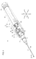
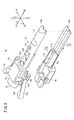
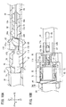
図1に示すように、カテーテル組立体10は、患者の体内に穿刺される穿刺部として、鋭利な針先12aを先端に有する管状の内針12と、内針12が挿入される外針として構成される管状のカテーテル14とを有する。また、カテーテル組立体10は、穿刺時の操作部として、内針12を保持する内針ハブ20と、カテーテル14を保持するカテーテルハブ30と、内針12の抜去時に内針12の針先12aを覆う針カバー40とを備える。
As shown in FIG. 1, a
なお、以下の説明では、図1に記載の方向指示に基づき、カテーテル組立体10の方向を示すこともある。すなわち、カテーテル組立体10の軸方向をX方向(針先12aがある先端方向をX1方向、内針ハブ20の基端がある基端方向をX2方向)と呼ぶ。また、カテーテル組立体10の幅方向をY方向(図1中の斜め左方向をY1方向、斜め右方向をY2方向)とも呼ぶ。さらに、カテーテル組立体10の上下方向をZ方向(図1中の上方向をZ1方向、下方向をZ2方向)とも呼ぶ。なお、これらの方向は説明の便宜上のものであり、カテーテル組立体10を任意の向きで使用できることは勿論である。
In the following description, the direction of the
先ず、本発明の理解の容易化のため、カテーテル組立体10の使用方法について概略的に説明する。カテーテル組立体10は、ユーザ(医師や看護師等)により内針ハブ20が把持操作されて、穿刺部の穿刺が行われる。穿刺部は、使用前(患者への穿刺前)の初期状態では、内針12がカテーテル14に挿通され且つ内針12がカテーテル14の先端から所定長だけ突出した2重管構造となっている。以下では、カテーテル組立体10の初期状態のことを「穿刺可能状態」ということもある。また、カテーテル組立体10の初期状態では、内針ハブ20とカテーテルハブ30が、針カバー40を介して接続されている。
First, in order to facilitate understanding of the present invention, a method of using the
カテーテル組立体10は、穿刺可能状態で、ユーザの穿刺行為により、内針12及びカテーテル14が共に患者の血管内に挿入される。患者への穿刺後、ユーザは、カテーテル14及びカテーテルハブ30の穿刺位置を固定して、内針ハブ20を患者から引き離すように後退移動させることで、内針12の抜去操作を行う。これにより、内針ハブ20に保持された内針12及び針カバー40も後退移動し、カテーテルハブ30と針カバー40の離脱がなされる。
The
その結果、カテーテル組立体10のうち、内針12、内針ハブ20及び針カバー40が患者側から離され、カテーテル14とカテーテルハブ30だけが患者側に留置された状態となる。内針12の抜去操作後、ユーザは、留置されたカテーテルハブ30の基端側に図示しない輸液チューブのコネクタを接続することで輸液ラインを構築し、患者への輸液剤(薬液)の供給を行う。
As a result, in the
一方、内針12の抜去操作に際して、内針ハブ20及び針カバー40は、内針12の収容動作を行う。この場合、内針ハブ20に対し針カバー40が伸長して、内針ハブ20及び針カバー40内に内針12を収容することにより、内針12の外部への露出を防止する。以下では、内針12の抜去操作後の内針ハブ20及び針カバー40の状態のことを「抜去後状態」ということもある。
On the other hand, when the
以下、このカテーテル組立体10の各構成について、図1、図2、図3A〜図3C及び図4を参照して具体的に説明する。
Hereinafter, each configuration of the
カテーテル組立体10の内針12は、患者の皮膚を穿刺可能な剛性を有する管状部材である。内針12は、穿刺可能状態(図3A参照)で、針先12aがカテーテル14の先端開口から突出し、長手方向の途中部位がカテーテルハブ30の内部を挿通し、基端側が内針ハブ20の内部で保持される長さに形成されている。内針12の構成材料としては、例えば、ステンレス鋼、アルミニウム又はアルミニウム合金、チタン又はチタン合金のような金属材料が挙げられる。
The
内針12と共に穿刺部を構成するカテーテル14は、可撓性を有する細径の管状部材であり、患者の体内に確実に導入及び留置される長さに形成されている。カテーテル14の内部には、カテーテル14の軸線方向に沿って内腔14aが貫通形成されている。内腔14aは、内針12を挿通可能な内径を有する。
The
カテーテル14の構成材料としては、樹脂材料、特に、軟質樹脂材料が好適である。この場合、例えば、ポリテトラフルオロエテレン(PTFE)、エチレン・テトラフルオロエテレン共重合体(ETFE)、ベルフルオロアルコキシフッ素樹脂(PFA)等のフッ素系樹脂、ポリエチレン、ポリプロピレン等のオレフィン系樹脂又はこれらの混合物、ポリウレタン、ポリエステル、ポリアミド、ポリエーテルナイロン樹脂、前記オレフィン系樹脂とエチレン−酢酸ビニル共重合体との混合物等が挙げられる。カテーテル14は、全部又は一部の内部を視認できるように、透明性を有する樹脂で構成されてもよい。
As a constituent material of the
カテーテル14の基端には、カテーテルハブ30が接続固定される。カテーテルハブ30は、先細りとなる筒状に形成され、この筒状の外形に応じた内部空間32を有する。内部空間32には、穿刺可能状態(図3A参照)で、カテーテルハブ30の軸方向に沿って内針12が配置される。内部空間32の先端側には、カテーテル14の基端部とカテーテルハブ30の先端部を液密に接続する図示しない接続機構(例えば、かしめピン等)が設けられる。また、カテーテルハブ30の基端外周面には、外方に突出し且つ周方向に延在するフランジ部34が設けられている。
A
カテーテルハブ30は、カテーテル組立体10の使用に際し、カテーテル14が血管に穿刺された状態で患者の体表に残され、テープ等により皮膚に貼り付けられて留置される。このカテーテルハブ30は、カテーテル14よりも硬質の材料によって構成されることが好ましい。カテーテルハブ30の構成材料は、特に限定されるものではないが、例えば、ポリプロピレン、ポリカーボネート、ポリアミド、ポリサルホン、ポリアリレート、メタクリレート−ブチレン−スチレン共重合体等の熱可塑性樹脂を好適に用いることができる。
When the
また、カテーテルハブ30は、患者側に留置される際に、上述したように輸液チューブのコネクタが接続される。このため、内部空間32には、コネクタの挿入にともない輸液ラインの経路を構築し得る図示しない接続機構(例えば、弁部、シール部材、プラグ等)が収容されることが好ましい。
Further, when the
一方、カテーテル組立体10の内針ハブ20は、穿刺可能状態で、カテーテルハブ30の基端側を部分的に覆っている。また、内針ハブ20は、抜去後状態では、針カバー40と共に内針12を収容する収容部材21として機能する。つまり、収容部材21は、内針ハブ20と針カバー40により構成される。この内針ハブ20は、カテーテル組立体10の基端側を構成しユーザに把持されるハブ本体50と、ハブ本体50の基端側内部に嵌合される中空状の内針固定部材60とを備える。
On the other hand, the
ハブ本体50は、細長い筒状体(外殻)であり、カテーテル組立体10の使用に際してユーザが把持操作し易いように適度の大きさ(太さ、長さ)に形成されている。ハブ本体50の内部には、針カバー40を収容する内針ハブ側中空部52が設けられている。内針ハブ側中空部52を構成する内周面52aの先端寄りには、内針12の抜去操作時に針カバー40(中継筒90)の離脱を規制するハブ本体側突部54が設けられている。
The
内針固定部材60は、内針ハブ側中空部52の基端側に収容固定される。この内針固定部材60は、内針ハブ側中空部52内において、先端側に向かって段階的に細径となる筒状を呈する。最も細径な先端部は、内針12の基端側を保持(密着固定)する保持部62として構成され、最も大径な基端部は、ハブ本体50の内周面に嵌合される嵌合部64として構成されている。
The inner
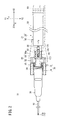
カテーテル組立体10の針カバー40は、穿刺可能状態(図3A参照)で、その基端側の大部分が内針ハブ20に収容され、先端側においてカテーテルハブ30を保持している。この針カバー40は、内筒70、外筒80、中継筒90の3つの筒状部材により構成される。内筒70、外筒80、中継筒90は、各々の筒部分の形状が順に太くなるように設計され、また筒部分の相互の軸心が同軸上となるように組み付けられる。
The
すなわち、内筒70は、その基端側が外筒80の内部に挿入されて外筒80と相対的に軸方向に移動自在となっている。外筒80は、その基端側が中継筒90の内部に挿入されて中継筒90と相対的に軸方向に移動自在となっている。さらに、中継筒90は、その全体がハブ本体50の内部に挿入されてハブ本体50と相対的に軸方向に移動自在となっている。針カバー40は、内筒70が外筒80に対し、外筒80が中継筒90に対し、中継筒90がハブ本体50に対しそれぞれ相対移動することで、ハブ本体50を含めて内針12を収容可能な長さに伸長する。
That is, the
針カバー40の内筒70は、内針12の収容時に内針12の針先12aを覆う針先保護部材として機能する。内筒70の先端は、穿刺可能状態(図3A参照)で、外筒80の先端よりも基端位置にあり、内針12の抜去操作にともない外筒80の先端から突出するように変位する。
The
内筒70は、図3A及び図4に示すように、軸方向に所定長さを有する中空状の内筒本体72と、この内筒本体72に一体形成されたアーム74とを備える。また、内筒本体72の内部には、内針12を通すことが可能な挿通孔73(収容空間)が、内筒本体72の軸線方向に沿って貫通形成されている。
As shown in FIGS. 3A and 4, the
内筒本体72は、アーム74が連結された中間筒部75と、中間筒部75から先端側に突出する先端筒部76と、中間筒部75から基端側に突出する基端筒部77とを有する。中間筒部75は、先端筒部76や基端筒部77よりも大きなサイズに形成され、その幅方向(Y方向)両側部にアーム74が一対連結されている。
The inner cylinder
一対のアーム74は、中間筒部75に連なる支持部74a(図8参照)と、支持部74aに連なり先端方向に平行に延びるアーム基部74bと、アーム基部74bに連なり幅方向外側且つ先端方向に突出するアーム突出部74cとを有する。アーム74は、外力が作用しない自然状態では、図4に示すようにアーム突出部74cが外筒80の幅方向よりも外側に拡がるように形成されている。そして、内筒70と外筒80が重なり合った穿刺可能状態で、外筒80の側壁により内側に寄るように弾性的に押さえられる(図2参照)。
The pair of
一対のアーム突出部74cの先端部には、幅方向内側に突出する突起74dが設けられている。一対の突起74dは、穿刺可能状態で、内側に寄ったアーム突出部74cによりカテーテルハブ30のフランジ部34に引っ掛かる。これにより、内筒70は、カテーテルハブ30の内部空間32の基端側に挿入された先端筒部76と突起74dとの間で、カテーテルハブ30を挟み込み、該カテーテルハブ30を強固に接続保持する。内針12の抜去操作時には、内筒70と外筒80の相対移動により、内筒70が外筒80の先端側に変位することで一対のアーム突出部74cを弾性的に拡開させ、突起74dによるフランジ部34の引っ掛かりを解除する。その結果、カテーテルハブ30は内筒70(針カバー40)からの離脱が許容される。
A
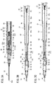
図3A〜図3Cに戻り、内筒70の先端筒部76は、カテーテルハブ30の内部空間32の内径に略一致する外径を有する円筒状に形成されている。一方、内筒70の基端筒部77は、先端筒部76に比べて軸方向に長く、且つ外筒80の外筒側中空部86の内径よりも小さい円筒状に形成される。基端筒部77の先端側(中間筒部75と基端筒部77の連結箇所)には、穿刺可能状態で、内筒70と外筒80の離脱を防止するストッパ部100と、ストッパ部100を変位可能とする変位許容空間110とが設けられている。これらの構成は、本発明の主要な特徴部分にあたり、後に詳述する。
Returning to FIGS. 3A to 3C, the distal
また、基端筒部77のストッパ部100よりも基端側の外周面には、内筒側突部77aが設けられている。この内筒側突部77aは、穿刺可能状態で外筒80の長孔88に挿入され、内筒70と外筒80の相対移動時に、内筒70と外筒80の所定以上の相対変位を規制する。これにより、内筒70が外筒80から完全に抜けることが防止される。
Further, an inner
針カバー40の外筒80は、内筒70の外側に配置される部材であり、内針12の収容時に内針12の先端寄りを覆う針先保護部材として機能する。外筒80は、先端側においてアーム74を収容可能なアーム収容部82と、アーム収容部82の基端から基端方向に所定長さ延びる筒状部84とを有する。また、筒状部84の内部には、軸方向に沿って外筒側中空部86が貫通形成されている。
The
アーム収容部82は、上部及び先端部が開口する比較的大きな箱状に形成されている。カテーテル組立体10の穿刺可能状態では、アーム収容部82の内部に、カテーテルハブ30の基端と内筒70の先端側(一対のアーム74及び中間筒部75等)が配置される。アーム収容部82のY方向の両側面には、外筒80の軸方向に対し平行に形成され、先端側が開口する凹溝82aが設けられる。凹溝82aには、アーム74が摺動可能に挿入され、内筒70と外筒80の相対移動時には、凹溝82aによりアーム74が案内される。
The
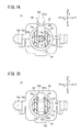
図5A及び図5Bに示すように、アーム収容部82の基端壁83は、外筒側中空部86の開口部86aを囲うように正面視で略U字状に形成され、基端側に形成される筒状部84に連なっている。すなわち、外筒側中空部86の開口部86aは、下部側のアーム収容部82の基端壁83と、筒状部84に連なる上部側の先端壁85(壁部)とにより構成されている。筒状部84の側周面には、先端壁85を基端壁83から分離する一対のスリット87が形成されている。
As shown in FIGS. 5A and 5B, the
筒状部84は、内筒70の基端筒部77よりも長い軸長を有するように形成されている。筒状部84の先端側には、上記のスリット87が所定長さ切り込まれており、これにより筒状部84の先端側は、上部壁84aと下部壁84bとに分割される。そして、上部壁84aの先端に上記の先端壁85が設けられている。
The
先端壁85は、アーム収容部82の基端壁83の軸方向形成位置に重なり、外筒側中空部86の開口部86aを構成する口縁には、先端面から基端方向に傾斜するテーパ面85a(外筒側傾斜面)を有する。また、上部壁84a及び下部壁84bの上下対向位置には、軸方向に所定長さを有する長孔88が形成されている。この長孔88は、外筒側中空部86に連通している。
The
図3A〜図3Cに示すように、筒状部84の基端側には、径方向外側に突出する外筒側突部89が外周面の周方向に沿って形成されている。この外筒側突部89は、筒状部84が中継筒90内に挿入された状態で、中継筒90の先端部に設けられた中継筒内側突部94に引っ掛かり可能となっている。これにより、外筒80と中継筒90の相対移動時に、外筒80と中継筒90の所定以上の相対変位が規制され、外筒80が中継筒90から完全に抜けることが防止される。
As shown in FIGS. 3A to 3C, an outer cylinder-
針カバー40の中継筒90は、外筒80の外側に配置される部材であり、内針12の収容時に内針12の胴体部分を覆う針先保護部材として機能する。中継筒90の内部には、軸方向に沿って中継筒側中空部92が貫通形成されている。中継筒90の先端の中継筒側中空部92を構成する内周面には、上記の中継筒内側突部94が形成されている。
The
また、中継筒90の基端側には、径方向外側に突出する中継筒外側突部96が外周面の周方向に沿って形成されている。この中継筒外側突部96は、中継筒90がハブ本体50の内針ハブ側中空部52内に挿入された状態で、ハブ本体50のハブ本体側突部54に引っ掛かり可能となっている。これにより、中継筒90と内針ハブ20の相対移動時に、中継筒90とハブ本体50の所定以上の相対変位が規制され、中継筒90がハブ本体50から完全に抜けることが防止される。
Further, on the proximal end side of the
針カバー40は、以上のように構成されることで、穿刺可能状態では内針12をカテーテル14の先端から露出させ、抜去後状態では内針12を内部に収容する。そして、本実施形態に係るカテーテル組立体10は、穿刺可能状態で、ストッパ部100が内筒70の径方向外側寄りの穿刺待機位置に配置されることにより、内筒70と外筒80の離脱を防止する。また、ストッパ部100は、抜去後状態で、内筒70の内針遮断位置に配置されることにより、針カバー40内に収容した内針12の進出(針先12aの飛び出し)を遮断する。以下、このストッパ部100の構成について、その周辺部分の構成と共に具体的に説明していく。
The
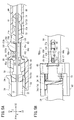
ストッパ部100は、図5Aに示すように、内筒70の変位許容空間110に配置されている。変位許容空間110は、基端筒部77の先端側において内筒70の軸方向と直交方向(Z方向)に貫通形成され、軸方向に延びる内筒70の挿通孔73に連通している。変位許容空間110は、ストッパ部100を、内筒70の上下方向にスライド可能に配置している。
As shown in FIG. 5A, the
ストッパ部100は、穿刺可能状態(挿通孔73に内針12が通った状態)では、内針12の側面に押し出されて、内筒70の穿刺待機位置(変位許容空間110の上部)に配置されている。この際、ストッパ部100は、図3Aに示すように、外筒80の長孔88を突き出て内針ハブ20の内針ハブ側中空部52に露出し、内針ハブ側中空部52を構成する内周面と内針12の間に存在する。
In a puncture enabled state (in which the
そのため、例えば、外筒80に対し内筒70を先端方向に相対移動させようとしても、ストッパ部100が長孔88の孔縁に当たり、内筒70が外筒80から進出することを阻むことができる。つまり、内針12の抜去操作時には、内針12が変位許容空間110を基端方向に抜けきるまでは、ストッパ部100が穿刺待機位置に維持される。この内筒70と外筒80の接続は、外筒80、中継筒90、ハブ本体50が軸方向に充分に伸長するまで続く。内針12が変位許容空間110よりも基端側に後退移動した後は、ストッパ部100が変位許容空間110の下方向にスライド可能となることで、内筒70と外筒80の相対移動にともないストッパ部100がスライドする。そして、外筒80の先端が後退して内筒70のアーム74を開かせることで、カテーテルハブ30が内筒70から離脱する。
Therefore, for example, even if the
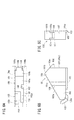
このストッパ部100の形状について、図6A〜図6Cを参照して詳述する。ストッパ部100は、所定形状を呈するブロック状の基部101と、基部101の先端から突出する突出片102及び連結部103と、基部101の基端から突出する基端突出部104と、基部101の下端から突出するフック部105とを有する。
The shape of the
基部101の上部は、側面視で山形に形成されている。基部101は、この山形の頂部から先端方向下側に向かって傾斜する先端傾斜面101aと、頂部から基端方向下側に向かって傾斜する基端傾斜面101b(逆側傾斜面)とを有する。基部101の幅は、変位許容空間110よりも幅狭に形成されるが、内筒70の挿通孔73の内径よりも大きく形成されている。また、基部101の頂部から下端までの高さは、変位許容空間110の上下高さよりも高く設定されている。
The upper part of the
この基部101のY2方向の側面(突出片102が連なる側面)には、上下方向に沿ってガイド溝106(溝部)が形成されている。このガイド溝106には、変位許容空間110を構成する内側面111に形成された側方凸部112が挿入される。これにより、ストッパ部100は、スライド時にガイド溝106が側方凸部112に案内されるので、姿勢が内筒70の軸方向に傾くこと等が防止される。
A guide groove 106 (groove portion) is formed along the vertical direction on the side surface of the
突出片102は、基部101のY2方向の側面に連なり、変位許容空間110の先端側の所定位置まで突出する略三角状に形成されている。突出片102の幅は、基部101の幅に対し幅狭な寸法に設定されている。この突出片102の上面102aは、先端傾斜面101aの傾斜がそのまま面一に連なっている。すなわち、先端傾斜面101aの先端は、図5Aに示すようにストッパ部100が穿刺待機位置にある場合でも、外筒80の外筒側中空部86内に入り込む位置まで下がっている。
The protruding
一方、連結部103は、ストッパ部100を内筒70と繋げるためのものであり、これにより内筒70の成形時にストッパ部100を一体成形することができる。具体的に、連結部103は、基部101の先端面のY1方向側に連なると共に、内筒70の変位許容空間110を構成する基端筒部77の壁面に連なっている。
On the other hand, the connecting
連結部103は、側面視でV字状に形成されており、基部101との連結箇所、谷箇所及び壁面との連結箇所が、その間の辺部を揺動自在とするヒンジ機構103aに構成されている。連結部103は、各ヒンジ機構103aが相互に連動することにより、変位許容空間110内においてストッパ部100の上下方向のスライドを安定的に実施させる。
The
ストッパ部100の基端突出部104は、基部101の基端面101cから基端方向に多少突出する程度であり、基部101の基端面101cの上部寄りに設けられている。基端突出部104の上面104aは、基部101の基端傾斜面101bの傾斜がそのまま面一に連なっている。
The base
また、基端面101cの基端突出部104よりも下側は、平坦状に形成されており、その面形状(幅及び高さ)は、挿通孔73の内径よりも大きく設定されている。この基端面101cの基端突出部104よりも下側の部分は、ストッパ部100が内針遮断位置に配置された状態で、内筒70の挿通孔73に対向する。よって、以下、この部分を「対向面107」ともいう。
In addition, the lower side of the base
ストッパ部100のフック部105は、基部101の下端面且つY1方向の側面に連なる位置に設けられており、基部101の軸方向に渡って形成されている。フック部105は、Y1方向に突出する爪部105aを有し、ストッパ部100が変位許容空間110内を下方向にスライドした際に、切り欠き部113に引っ掛かる。すなわち、フック部105及び切り欠き部113は、ストッパ部100のロック機構108(図7B参照)を構成している。
The
図7Aに示すように、切り欠き部113は、内筒70の変位許容空間110を構成する内側面111のうちY1方向側の内側面111に設けられている。切り欠き部113は、変位許容空間110に連なると共に下方に開口している。内針12の抜去操作時には、ストッパ部100が変位許容空間110の下方向にスライドし、図7Bに示すように内針遮断位置に移動することで、爪部105aが切り欠き部113に引っ掛かる。これにより、ストッパ部100の上方向へのスライドが規制され、ストッパ部100が内針遮断位置において待機状態となる。なお、ストッパ部100を内針遮断位置に待機させるロック機構108の構成は、特に限定されないことは勿論である。例えば、切り欠き部113がストッパ部100に、フック部105が内側面111に形成されていてもよい。
As shown in FIG. 7A,
以上のストッパ部100を有する内筒70は、製造(射出成形)時には、図8に示すように、2つの部材(第1部材78、第2部材79)に成形される。なお、図8中では発明の理解の容易化のため第1部材78と第2部材79を分離して示しているが、実施上では第1部材78と第2部材79の基端同士がヒンジ機構70aにより繋がり、一体的に射出成形される。すなわち、第1部材78と第2部材79は、基端(ヒンジ機構70a)を基点に先端側が上下に開く。なお、第1部材78と第2部材79は、別々に成形してもよい。
The
第1部材78は、内筒70の上側を構成し、内筒本体72の上部分とさらにアーム74を有する。ストッパ部100はこの第1部材78側に成形される。このストッパ部100を成形するため、ストッパ部100の周囲の第1部材78には、図示しない成形型が挿入されるように変位許容空間110よりも幅広な空間部78aが形成される。
The
第2部材79は、内筒本体72の下部分を構成している。第2部材79の基端筒部77において上記の空間部78aに対向する位置には、一対の突出壁79aが形成されている。一対の突出壁79aは、第1部材78の空間部78aに入り込むことが可能な肉厚を有し、相互に対向する面が変位許容空間110の内側面111となっている。すなわち、第1部材78と第2部材79は、不要な隙間を少なくして相互に組み付け合うインロー構造となっている。第1部材78と第2部材79を組付けた場合、第2部材79の一対の突出壁79aが、第1部材78の空間部78aを構成する側面とストッパ部100との隙間に入り込んで円筒状を構成する(図7Aも参照)。その結果、ストッパ部100は、比較的隙間が少ない一対の突出壁79aの間でスライド自在となる。
The
また、Y2方向の突出壁79aの内側面111には、上述した側方凸部112が形成されており、この側方凸部112は、ストッパ部100のガイド溝106に挿入される(図6A参照)。
Further, on the
さらに、一対の突出壁79aの基端側の内側面111には、ストッパ部100の基端突出部104に応じて変位許容空間110を若干狭める段差114が形成されている。この段差114は、下部側において挿通孔73に連なる。そのため、ストッパ部100が内針遮断位置に待機した状態で、変位許容空間110の基端側は、ストッパ部100の基端面101c及び基端突出部104、一対の突出壁79aの段差114、挿通孔73の内周面73aにより略閉じられる。針カバー40に収容された内針12は、針先12aがこの閉空間を臨むことにより、進出が防止される。
Further, on the
本実施形態に係るカテーテル組立体10は、基本的には以上のように構成されるものであり、以下、カテーテル組立体10の組み立て及び使用時の動作等に基づきその作用効果を説明する。
The
カテーテル組立体10の組み立てにおいては、針カバー40のうち外筒80及び中継筒90を内針ハブ20内に先に組み込み、後に内筒70を外筒80の先端側から挿入していく。そして、内筒70の基端筒部77が外筒80の外筒側中空部86内にある程度挿入された段階で、カテーテル14及びカテーテルハブ30を先端側に配した内針12を先端方向から挿入していく。この段階では、内筒70の先端が外筒80の先端よりも先端側にあり、一対のアーム74が拡開し、またストッパ部100が穿刺待機位置に配置されている。
In assembling the
内針12は、その基端から内筒70の先端筒部76に開口している挿通孔73に挿入され、中間筒部75及び基端筒部77を介して内筒70の基端側に露出される。この際、ストッパ部100が穿刺待機位置にあることから、内針12は変位許容空間110をスムーズに通過する。内筒70の基端側に露出された内針12の基端は、外筒側中空部86内を軸方向に移動して、内針固定部材60の保持部62に到達する。内針12の基端部は、保持部62の先端から内針固定部材60の内部に挿入されることで保持部62内に設けられた図示しないパッキンを貫通しつつ保持部62に固定保持される。
The
内針12の固定後は、カテーテルハブ30を先端筒部76に装着し、さらに内筒70を外筒80と相対的に基端方向に押し込むことで、内筒70を外筒80に組み付ける。この際、ストッパ部100(及び内筒側突部77a)は、図9に示すように、外筒側中空部86の開口部86aよりも径方向外側に突出している。しかしながら、外筒80の筒状部84にスリット87(図5B参照)が形成されていることで、ストッパ部100は、開口部86aの通過時に、筒状部84の上部壁84a及び先端壁85を上方向に変位させる。そのため、ストッパ部100(及び内筒側突部77a)は、基端方向への組み込みが弾性的に許容される。
After the
また、外筒80の先端壁85は、ストッパ部100の基端傾斜面101bに対向するようにテーパ面85aを備える。そのため、ストッパ部100が基端方向に移動すると、基端傾斜面101bとテーパ面85aが接触し合い、先端壁85の上方向への変位を案内することができる。ストッパ部100は、先端壁85を基端方向に抜けると長孔88内に配置される。
Further, the
また、内筒70の基端方向の移動にともない、内筒70のアーム74が外筒80により閉じられることで、突起74dがカテーテルハブ30のフランジ部34に引っ掛かる。これにより、カテーテル組立体10は、内針12とカテーテル14が2重管構造をとり、且つ内針ハブ20、カテーテルハブ30及び針カバー40が一体化した穿刺可能状態となる。カテーテル組立体10は、この穿刺可能状態において、滅菌等の外部環境保護手段が施されてユーザに提供される。
Further, as the
ユーザは、カテーテル組立体10の使用時には、上述したように穿刺部(内針12及びカテーテル14)を患者の体内に一体的に穿刺する。図5Aに示すように、穿刺待機位置にあるストッパ部100は、内筒70と外筒80との相対移動を抑制し且つ下端面により内針12を押さえることで穿刺部のぶれ等を抑止することができる。
When using the
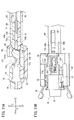
穿刺後は、内針12の抜去操作を実施する。ユーザは、カテーテルハブ30を一方の手で固定し、他方の手で内針ハブ20を把持してこの内針ハブ20を後退移動させる。この内針ハブ20の後退移動により、ハブ本体50が中継筒90に対し相対的に後退移動する。そして、ハブ本体50が所定量後退移動すると、ハブ本体側突部54が中継筒外側突部96に引っ掛かる。これにより中継筒90がハブ本体50に引き出され、外筒80と相対的に後退移動する。また、中継筒90が所定量後退移動すると、中継筒内側突部94が外筒側突部89に引っ掛かる。これにより外筒80が中継筒90に引き出され、内筒70と相対的に後退移動する。
After puncturing, the
図5A及び図5Bに示すように、ハブ本体50、中継筒90、外筒80の後退移動前は、ストッパ部100が穿刺待機位置にあり、内針12によりストッパ部100の上下方向のスライドが規制されている。そのため、ストッパ部100は内筒70と外筒80の離脱(相対移動)を防ぐことができる。
As shown in FIGS. 5A and 5B, before the
中継筒90が外筒80を引き出す段階では、図3Bに示すように、内針12の針先12aが変位許容空間110よりも基端側に移動した状態となる。そのため、ストッパ部100が穿刺待機位置から内筒70の下方向(X2方向)に移動可能となり、内筒70に対する外筒80の後退移動が許容される。
At the stage where the
つまり、外筒80が内筒70と相対的に後退移動すると、外筒80の長孔88の孔縁(上部壁84a)がストッパ部100の突出片102の上面102a(先端傾斜面101a)に当たる。そのため、外筒80の後退移動にともない上部壁84aがストッパ部100の先端傾斜面101aを滑り、ストッパ部100を変位許容空間110の下方向にスライドさせていく。ストッパ部100は、外筒80の外筒側中空部86内を通過可能な内針遮断位置まで押し下げられることになる。
That is, when the
外筒80が内筒70に対し所定量後退移動した段階では、図10A及び図10Bに示すように、ストッパ部100の頂部が外筒80のアーム収容部82内に入り込む。この段階では、ストッパ部100のフック部105が内筒70の切り欠き部113に引っ掛かり、ストッパ部100は、内針遮断位置に配置された状態が維持される。
At a stage where the
外筒80がさらに後退移動すると、図11A及び図11Bに示すように、外筒80の上部壁84aが内筒70の内筒側突部77aに引っ掛かる。これにより、内筒70が、外筒80に引き出されて基端方向に移動する。また、この段階では、一対のアーム74がアーム収容部82から開放されて幅方向外側に拡開する。よって、突起74dに引っ掛けられていたカテーテルハブ30は、針カバー40からスムーズに離脱され、カテーテル14及びカテーテルハブ30が患者側に留置される。留置後、カテーテルハブ30には輸液チューブが接続される。
When the
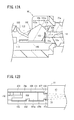
一方、分離した内針12、内針ハブ20及び針カバー40は、医療廃棄処理がなされる。この際、内針ハブ20及び針カバー40は、穿刺に用いた内針12を外部に露出しないように収容する。すなわち、図12A及び図12Bに示すように、ストッパ部100が内針遮断位置に配置されていることで、内針12の進出経路である基端筒部77の挿通孔73先端側を閉塞する。このため、内筒70の先端方向に内針ハブ20等を押し出しても、ストッパ部100の対向面107により内針12の進出を遮断することができる。
On the other hand, the separated
特に、針先12aの収容部分は、対向面107が内針12のX1方向を閉塞し、基端突出部104がZ1方向を覆い、段差114がY方向両側を覆い、挿通孔73の内周面73aがZ2方向を覆っている。そのため、内針12が先端方向に抜け出る隙間がなくなり、内針12の進出を良好に遮断する。また、ストッパ部100は、ガイド溝106と側方凸部112の引っ掛かりにより、内筒70の軸方向(X方向)への移動が規制されているため、内針12から押出力(進出力)を受けても遮断状態を維持することができる。
In particular, in the accommodating portion of the
以上のように、本実施形態に係るカテーテル組立体10は、内筒70と外筒80の離脱を防止するストッパ部100を、内針12の抜去時にスライドして内針遮断位置に配置する。このため、ストッパ部100により内針12の進出を良好に防止することができる。また、カテーテル組立体10は、ストッパ部100が内筒70に一体成形されていることにより、内針12の進出を遮断する部材を別部材として用意(製造)し、内筒70内に組み付ける必要がなくなる。このため、このカテーテル組立体10は、製造コストを大幅に低減することができると共に、組立作業を簡単化させて製造効率を向上することができる。
As described above, in the
この場合、ストッパ部100は、先端傾斜面101aを有することで、外筒80の相対移動において上部壁84aに接触した先端傾斜面101aに沿ってスムーズにスライドする。よって、内針12の抜去操作を容易に行わせることができる。また、ストッパ部100の突出片102が、外筒80の外筒側中空部86の開口部86a(上部壁84a)付近まで突出していることで、外筒80の相対移動の初期に先端傾斜面101aを上部壁84aに確実に接触させることができる。これにより、ストッパ部100のスライドが一層容易に案内される。
In this case, since the
また、連結部103により内筒70とストッパ部100が連結していることで、内筒70の一体成形及び組立を容易に行うことができる。連結部103は、ヒンジ機構103aを有することで、内筒70に対するストッパ部100のスライドを良好に実施させる。さらに、カテーテル組立体10は、ストッパ部100にガイド溝106が形成され、変位許容空間110の内側面111に側方凸部112が形成されていることで、スライド時にストッパ部100の姿勢の傾き等を阻止することができる。なお、ストッパ部100に凸部が設けられ、内側面111に溝部が設けられてもよいことは勿論である。
Further, since the
またさらに、カテーテル組立体10は、ロック機構108によりスライド後のストッパ部100を内針遮断位置に確実に待機させ続けることができる。よって、針カバー40に収容した内針12の飛び出し等をより確実に遮断することができる。さらにまた、内筒70が第1部材78と第2部材79により構成された内筒70の組み付けより、突出壁79aがストッパ部100の周囲を囲うことで、変位許容空間110の隙間が減少して内針12の飛び出しをさらに確実に防止することが可能となる。
Still further, the
上記において、本発明について好適な実施形態を挙げて説明したが、本発明は前記実施形態に限定されるものではなく、本発明の要旨を逸脱しない範囲において、種々の改変が可能なことは言うまでもない。 In the above description, the present invention has been described with reference to preferred embodiments. However, the present invention is not limited to the above-described embodiments, and various modifications can be made without departing from the scope of the present invention. Yes.
Claims (9)
前記針カバー(40)は、前記カテーテル(14)を保持するカテーテルハブ(30)に着脱可能な内筒(70)と、
少なくとも前記内筒(70)の一部を覆い、前記内針(12)の抜去時に前記内筒(70)に対し相対移動する外筒(80)とを有し、
前記内筒(70)は、前記カテーテル(14)に前記内針(12)が挿通された状態で、前記内筒(70)の径方向外側寄りの待機位置に配置されることにより前記内筒(70)と前記外筒(80)の相対移動を防止するストッパ部(100)を有し、
前記ストッパ部(100)は、前記内針(12)の抜去時に前記外筒(80)の前記内筒(70)に対する相対移動にともない内針遮断位置にスライドする
ことを特徴とするカテーテル組立体(10)。An inner needle (12), a catheter (14) through which the inner needle (12) is inserted, and a needle cover that accommodates the inner needle (12) when the inner needle (12) is removed from the catheter (14) A catheter assembly (10) comprising:
The needle cover (40) includes an inner cylinder (70) detachably attached to a catheter hub (30) holding the catheter (14),
An outer cylinder (80) that covers at least a part of the inner cylinder (70) and moves relative to the inner cylinder (70) when the inner needle (12) is removed;
The inner cylinder (70) is disposed at a standby position closer to the radially outer side of the inner cylinder (70) in a state where the inner needle (12) is inserted through the catheter (14). (70) and a stopper portion (100) for preventing relative movement between the outer cylinder (80),
The stopper portion (100) slides to an inner needle blocking position as the outer cylinder (80) moves relative to the inner cylinder (70) when the inner needle (12) is removed. (10).
前記ストッパ部(100)は、前記内筒(70)の軸方向に対し傾斜する傾斜面(101a)を有し、前記外筒(80)の前記内筒(70)に対する相対移動にともない前記傾斜面(101a)が前記外筒(80)の一部に接触して押されることにより前記内針遮断位置にスライドする
ことを特徴とするカテーテル組立体(10)。The catheter assembly (10) of claim 1,
The stopper portion (100) has an inclined surface (101a) that is inclined with respect to the axial direction of the inner cylinder (70), and the inclination as the outer cylinder (80) moves relative to the inner cylinder (70). The catheter assembly (10), wherein the surface (101a) slides to the inner needle blocking position by being pressed against a part of the outer cylinder (80).
前記外筒(80)は、前記内筒(70)が挿通される中空部(86)を有し、
前記傾斜面(101a)は、前記ストッパ部(100)が前記待機位置に配置された状態で前記中空部(86)に入り込む
ことを特徴とするカテーテル組立体(10)。Catheter assembly (10) according to claim 2,
The outer cylinder (80) has a hollow portion (86) through which the inner cylinder (70) is inserted,
The catheter assembly (10), wherein the inclined surface (101a) enters the hollow portion (86) in a state where the stopper portion (100) is disposed at the standby position.
前記ストッパ部(100)は、前記傾斜面(101a)の反対位置に逆側傾斜面(101b)を有し、且つ前記カテーテル(14)に前記内針(12)が挿通された状態で、前記内針(12)により前記待機位置から径方向内側へのスライドが規制されており、
前記外筒(80)は、前記ストッパ部(100)よりも先端側に前記外筒(80)の径方向外側に変位可能な壁部(85)を備え、前記壁部(85)は、前記逆側傾斜面(101b)に略平行な外筒側傾斜面(85a)を有する
ことを特徴とするカテーテル組立体(10)。Catheter assembly (10) according to claim 3,
The stopper portion (100) has a reverse inclined surface (101b) at a position opposite to the inclined surface (101a), and the inner needle (12) is inserted through the catheter (14). The inner needle (12) restricts sliding inward in the radial direction from the standby position,
The outer cylinder (80) includes a wall part (85) that is displaceable radially outward of the outer cylinder (80) on the tip side of the stopper part (100), and the wall part (85) A catheter assembly (10) having an outer cylinder side inclined surface (85a) substantially parallel to the reverse inclined surface (101b).
前記内筒(70)と前記ストッパ部(100)は、該ストッパ部(100)をスライド自在とするヒンジ機構(103a)を有する連結部(103)により連結されている
ことを特徴とするカテーテル組立体(10)。The catheter assembly (10) of claim 1,
The inner cylinder (70) and the stopper portion (100) are connected by a connecting portion (103) having a hinge mechanism (103a) that allows the stopper portion (100) to slide freely. Solid (10).
前記内筒(70)及び前記ストッパ部(100)のうち一方には、前記ストッパ部(100)のスライド方向に沿って延在する溝部(106)が形成され、
前記内筒(70)及び前記ストッパ部(100)の他方には、前記溝部(106)に挿入される凸部(112)が形成される
ことを特徴とするカテーテル組立体(10)。The catheter assembly (10) of claim 1,
A groove (106) extending along the sliding direction of the stopper (100) is formed on one of the inner cylinder (70) and the stopper (100),
The other of the inner cylinder (70) and the stopper part (100) is formed with a convex part (112) inserted into the groove part (106). Catheter assembly (10).
前記内筒(70)及び前記ストッパ部(100)には、前記ストッパ部(100)が前記内針遮断位置にスライドした際に変位状態を維持するロック機構(108)が設けられている
ことを特徴とするカテーテル組立体(10)。The catheter assembly (10) of claim 1,
The inner cylinder (70) and the stopper portion (100) are provided with a lock mechanism (108) that maintains a displaced state when the stopper portion (100) slides to the inner needle blocking position. Feature catheter assembly (10).
前記内筒(70)は、前記ストッパ部(100)と、前記ストッパ部(100)を非接触で囲う空間部(78a)とを有する第1部材(78)と、前記第1部材(78)に組み付けられる第2部材(79)とにより構成され、
前記第2部材(79)は、前記ストッパ部(100)の両側方の隙間を幅狭にするように前記空間部(78a)に収容される突出壁(79a)を有する
ことを特徴とするカテーテル組立体(10)。The catheter assembly (10) according to any one of claims 1 to 7,
The inner cylinder (70) includes a first member (78) having the stopper portion (100) and a space portion (78a) surrounding the stopper portion (100) in a non-contact manner, and the first member (78). And a second member (79) assembled to
The second member (79) has a protruding wall (79a) accommodated in the space (78a) so as to narrow a gap on both sides of the stopper (100). Assembly (10).
前記ストッパ部(100)は、前記内針遮断位置において前記内針(12)の収容空間(73)の一部を囲う突出部(104)を有し、
前記突出壁(79a)は、前記突出部(104)の両側方の隙間も幅狭にする
ことを特徴とするカテーテル組立体(10)。The catheter assembly (10) according to claim 8,
The stopper portion (100) has a protruding portion (104) surrounding a part of the accommodation space (73) of the inner needle (12) at the inner needle blocking position,
The catheter assembly (10), wherein the protruding wall (79a) narrows the gaps on both sides of the protruding portion (104).
Applications Claiming Priority (1)
| Application Number | Priority Date | Filing Date | Title |
|---|---|---|---|
| PCT/JP2013/065675 WO2014196050A1 (en) | 2013-06-06 | 2013-06-06 | Catheter assembly |
Publications (2)
| Publication Number | Publication Date |
|---|---|
| JPWO2014196050A1 JPWO2014196050A1 (en) | 2017-02-23 |
| JP6134792B2 true JP6134792B2 (en) | 2017-05-24 |
Family
ID=52007726
Family Applications (1)
| Application Number | Title | Priority Date | Filing Date |
|---|---|---|---|
| JP2015521228A Active JP6134792B2 (en) | 2013-06-06 | 2013-06-06 | Catheter assembly |
Country Status (7)
| Country | Link |
|---|---|
| US (1) | US20160089513A1 (en) |
| EP (1) | EP3006074B1 (en) |
| JP (1) | JP6134792B2 (en) |
| CN (1) | CN105263558B (en) |
| AU (1) | AU2013391601A1 (en) |
| CA (1) | CA2914590A1 (en) |
| WO (1) | WO2014196050A1 (en) |
Cited By (1)
| Publication number | Priority date | Publication date | Assignee | Title |
|---|---|---|---|---|
| JP3126470B2 (en) | 1992-03-11 | 2001-01-22 | 旭電化工業株式会社 | Deodorized cocoa butter with no return odor |
Families Citing this family (22)
| Publication number | Priority date | Publication date | Assignee | Title |
|---|---|---|---|---|
| WO2007006055A2 (en) | 2005-07-06 | 2007-01-11 | Vascular Pathways Inc. | Intravenous catheter insertion device and method of use |
| JP5139518B2 (en) | 2007-05-07 | 2013-02-06 | バスキュラー・パスウェイズ・インコーポレイテッド | Venous catheter insertion device |
| US11925779B2 (en) | 2010-05-14 | 2024-03-12 | C. R. Bard, Inc. | Catheter insertion device including top-mounted advancement components |
| US9950139B2 (en) | 2010-05-14 | 2018-04-24 | C. R. Bard, Inc. | Catheter placement device including guidewire and catheter control elements |
| WO2012154277A1 (en) | 2011-02-25 | 2012-11-15 | C.R. Bard, Inc. | Medical component insertion device including a retractable needle |
| USD903101S1 (en) | 2011-05-13 | 2020-11-24 | C. R. Bard, Inc. | Catheter |
| RU2648229C1 (en) | 2013-11-14 | 2018-03-22 | Эквисис, Инк. | Intraocular shunt device |
| WO2016037127A1 (en) * | 2014-09-05 | 2016-03-10 | C.R. Bard, Inc. | Catheter insertion device including retractable needle |
| USD903100S1 (en) | 2015-05-01 | 2020-11-24 | C. R. Bard, Inc. | Catheter placement device |
| EP3294380B1 (en) | 2015-05-15 | 2022-03-23 | C. R. Bard, Inc. | Catheter insertion device |
| JP6768644B2 (en) * | 2015-05-15 | 2020-10-14 | テルモ株式会社 | Catheter assembly |
| JP6872488B2 (en) * | 2015-09-24 | 2021-05-19 | テルモ株式会社 | Catheter assembly |
| JP6748090B2 (en) * | 2015-09-24 | 2020-08-26 | テルモ株式会社 | Catheter assembly |
| JP6712481B2 (en) * | 2016-03-30 | 2020-06-24 | テルモ株式会社 | Catheter assembly |
| US10493262B2 (en) | 2016-09-12 | 2019-12-03 | C. R. Bard, Inc. | Blood control for a catheter insertion device |
| JP6953541B2 (en) | 2017-03-01 | 2021-10-27 | シー・アール・バード・インコーポレーテッドC R Bard Incorporated | Catheter insertion device |
| US11389626B2 (en) | 2018-03-07 | 2022-07-19 | Bard Access Systems, Inc. | Guidewire advancement and blood flashback systems for a medical device insertion system |
| US11135089B2 (en) * | 2018-03-09 | 2021-10-05 | Aquesys, Inc. | Intraocular shunt inserter |
| USD921884S1 (en) | 2018-07-27 | 2021-06-08 | Bard Access Systems, Inc. | Catheter insertion device |
| JP7721504B2 (en) | 2019-08-19 | 2025-08-12 | ベクトン・ディキンソン・アンド・カンパニー | Midline Catheter Placement Device |
| EP4025288A1 (en) | 2019-09-20 | 2022-07-13 | Bard Peripheral Vascular, Inc. | Intravenous catheter-placement device |
| CN114650863B (en) * | 2019-11-14 | 2023-07-21 | 泰尔茂株式会社 | catheter assembly |
Family Cites Families (19)
| Publication number | Priority date | Publication date | Assignee | Title |
|---|---|---|---|---|
| US4834718A (en) * | 1987-06-01 | 1989-05-30 | Michael McDonald | Safety needle apparatus |
| US5584810A (en) | 1995-07-11 | 1996-12-17 | Becton Dickinson And Company | Needle point guard assembly |
| DK2319556T3 (en) * | 1996-02-27 | 2013-06-17 | Braun Melsungen Ag | Needle tip protector for needles |
| JP4245196B2 (en) * | 1996-07-03 | 2009-03-25 | 東郷メディキット株式会社 | Medical puncture device |
| JP3576765B2 (en) * | 1997-08-22 | 2004-10-13 | テルモ株式会社 | Indwelling needle assembly |
| AUPO915797A0 (en) * | 1997-09-11 | 1997-10-02 | Noble House Group Pty Ltd | Needle guard and assembly |
| US5997507A (en) * | 1998-08-07 | 1999-12-07 | Dysarz; Edward D. | Biased spring hard needle retractable IV catheter |
| US6620136B1 (en) * | 1999-02-18 | 2003-09-16 | Medsafe Technologies, Llc | Retractable I-V catheter placement device |
| US6461362B1 (en) * | 2001-04-30 | 2002-10-08 | Mdc Investment Holdings, Inc. | Catheter insertion device with retractable needle |
| ITBO20010497A1 (en) * | 2001-07-31 | 2003-01-31 | Delta Med S R L | PROTECTION DEVICE FOR NEEDLE-CANNULA |
| EP1386633A1 (en) * | 2002-08-02 | 2004-02-04 | Sergio Restelli | Safety catheter |
| EP1475124A1 (en) * | 2003-05-09 | 2004-11-10 | Sergio Restelli | Safety catheter |
| FR2867082B1 (en) * | 2004-03-02 | 2006-05-26 | Vygon | TILTING DEVICE FOR POSITIONING A CANNULA INTO A VEIN |
| US8303543B2 (en) * | 2005-03-07 | 2012-11-06 | Ramzi Abulhaj | Bloodless catheter and needle shielding catheter insertion apparatus |
| CA2822982C (en) * | 2010-12-02 | 2016-01-19 | Erskine Medical Llc | Needle shield assembly with hub engagement member for needle device |
| MX376645B (en) * | 2011-04-07 | 2025-03-07 | Erskine Medical Llc | NEEDLE SHIELDING DEVICE. |
| CN202777289U (en) * | 2011-12-29 | 2013-03-13 | 泰尔茂株式会社 | Detaining needle |
| JP6129825B2 (en) * | 2012-05-16 | 2017-05-17 | テルモ株式会社 | Catheter assembly |
| JP6028021B2 (en) * | 2012-05-16 | 2016-11-16 | テルモ株式会社 | Catheter assembly |
-
2013
- 2013-06-06 EP EP13886262.8A patent/EP3006074B1/en not_active Not-in-force
- 2013-06-06 CN CN201380077177.5A patent/CN105263558B/en active Active
- 2013-06-06 AU AU2013391601A patent/AU2013391601A1/en not_active Abandoned
- 2013-06-06 JP JP2015521228A patent/JP6134792B2/en active Active
- 2013-06-06 CA CA2914590A patent/CA2914590A1/en not_active Abandoned
- 2013-06-06 WO PCT/JP2013/065675 patent/WO2014196050A1/en not_active Ceased
-
2015
- 2015-12-04 US US14/959,609 patent/US20160089513A1/en not_active Abandoned
Cited By (1)
| Publication number | Priority date | Publication date | Assignee | Title |
|---|---|---|---|---|
| JP3126470B2 (en) | 1992-03-11 | 2001-01-22 | 旭電化工業株式会社 | Deodorized cocoa butter with no return odor |
Also Published As
| Publication number | Publication date |
|---|---|
| WO2014196050A1 (en) | 2014-12-11 |
| EP3006074A4 (en) | 2017-03-01 |
| CN105263558A (en) | 2016-01-20 |
| EP3006074B1 (en) | 2018-02-21 |
| JPWO2014196050A1 (en) | 2017-02-23 |
| EP3006074A1 (en) | 2016-04-13 |
| CN105263558B (en) | 2019-07-12 |
| CA2914590A1 (en) | 2014-12-11 |
| AU2013391601A1 (en) | 2015-12-24 |
| US20160089513A1 (en) | 2016-03-31 |
Similar Documents
| Publication | Publication Date | Title |
|---|---|---|
| JP6134792B2 (en) | Catheter assembly | |
| JP6966592B2 (en) | Catheter assembly | |
| JP4921779B2 (en) | Indwelling needle | |
| US10905858B2 (en) | Safety needle system operable with a medical device | |
| JP6616399B2 (en) | Catheter assembly | |
| JP6138921B2 (en) | Catheter assembly | |
| KR20110116237A (en) | Medical needle device | |
| JPWO2015115316A1 (en) | Catheter assembly | |
| US20190175878A1 (en) | Catheter assembly | |
| JP2020175268A (en) | Catheter assembly | |
| JP6129825B2 (en) | Catheter assembly | |
| WO2014196243A1 (en) | Catheter assembly | |
| WO2016152415A1 (en) | Catheter assembly | |
| WO2013141347A1 (en) | Puncture tool | |
| WO2014196051A1 (en) | Catheter assembly | |
| JP2015171451A (en) | catheter assembly | |
| JP6444234B2 (en) | Catheter assembly | |
| JP2011206609A (en) | Indwelling needle |
Legal Events
| Date | Code | Title | Description |
|---|---|---|---|
| TRDD | Decision of grant or rejection written | ||
| A01 | Written decision to grant a patent or to grant a registration (utility model) |
Free format text: JAPANESE INTERMEDIATE CODE: A01 Effective date: 20170328 |
|
| A61 | First payment of annual fees (during grant procedure) |
Free format text: JAPANESE INTERMEDIATE CODE: A61 Effective date: 20170424 |
|
| R150 | Certificate of patent or registration of utility model |
Ref document number: 6134792 Country of ref document: JP Free format text: JAPANESE INTERMEDIATE CODE: R150 |
|
| R250 | Receipt of annual fees |
Free format text: JAPANESE INTERMEDIATE CODE: R250 |
|
| R250 | Receipt of annual fees |
Free format text: JAPANESE INTERMEDIATE CODE: R250 |
|
| S111 | Request for change of ownership or part of ownership |
Free format text: JAPANESE INTERMEDIATE CODE: R313117 |
|
| S531 | Written request for registration of change of domicile |
Free format text: JAPANESE INTERMEDIATE CODE: R313531 |
|
| R350 | Written notification of registration of transfer |
Free format text: JAPANESE INTERMEDIATE CODE: R350 |
|
| R250 | Receipt of annual fees |
Free format text: JAPANESE INTERMEDIATE CODE: R250 |
|
| R250 | Receipt of annual fees |
Free format text: JAPANESE INTERMEDIATE CODE: R250 |
|
| R250 | Receipt of annual fees |
Free format text: JAPANESE INTERMEDIATE CODE: R250 |
|
| R250 | Receipt of annual fees |
Free format text: JAPANESE INTERMEDIATE CODE: R250 |