JP6134729B2 - Device for monitoring arterial pulse waves in diagnosing various medical conditions - Google Patents
Device for monitoring arterial pulse waves in diagnosing various medical conditions Download PDFInfo
- Publication number
- JP6134729B2 JP6134729B2 JP2014542995A JP2014542995A JP6134729B2 JP 6134729 B2 JP6134729 B2 JP 6134729B2 JP 2014542995 A JP2014542995 A JP 2014542995A JP 2014542995 A JP2014542995 A JP 2014542995A JP 6134729 B2 JP6134729 B2 JP 6134729B2
- Authority
- JP
- Japan
- Prior art keywords
- finger
- occlusion
- probe
- amplitude
- baseline
- Prior art date
- Legal status (The legal status is an assumption and is not a legal conclusion. Google has not performed a legal analysis and makes no representation as to the accuracy of the status listed.)
- Expired - Fee Related
Links
- 238000012544 monitoring process Methods 0.000 title claims description 14
- 239000000523 sample Substances 0.000 claims description 105
- 238000012937 correction Methods 0.000 claims description 50
- 238000000926 separation method Methods 0.000 claims description 40
- 238000005259 measurement Methods 0.000 claims description 33
- 230000002093 peripheral effect Effects 0.000 claims description 24
- 239000012530 fluid Substances 0.000 claims description 21
- 238000000034 method Methods 0.000 claims description 20
- 230000008859 change Effects 0.000 claims description 18
- 230000035485 pulse pressure Effects 0.000 claims description 16
- 230000004044 response Effects 0.000 claims description 16
- 230000003068 static effect Effects 0.000 claims description 15
- 208000031104 Arterial Occlusive disease Diseases 0.000 claims description 12
- 208000021328 arterial occlusion Diseases 0.000 claims description 12
- 230000006870 function Effects 0.000 claims description 11
- 230000003287 optical effect Effects 0.000 claims description 6
- 230000000541 pulsatile effect Effects 0.000 claims description 6
- 230000002411 adverse Effects 0.000 claims description 5
- 208000006440 Open Bite Diseases 0.000 claims description 4
- 230000005355 Hall effect Effects 0.000 claims description 3
- 210000003743 erythrocyte Anatomy 0.000 claims description 3
- 230000004907 flux Effects 0.000 claims description 3
- 230000014759 maintenance of location Effects 0.000 claims description 3
- 239000000463 material Substances 0.000 claims description 3
- 210000001367 artery Anatomy 0.000 claims description 2
- 230000009466 transformation Effects 0.000 claims description 2
- 230000008321 arterial blood flow Effects 0.000 claims 2
- 238000009529 body temperature measurement Methods 0.000 claims 2
- 238000000424 optical density measurement Methods 0.000 claims 2
- 238000002106 pulse oximetry Methods 0.000 claims 2
- 230000008320 venous blood flow Effects 0.000 claims 2
- 108010076282 Factor IX Proteins 0.000 claims 1
- 210000003811 finger Anatomy 0.000 description 120
- 210000001519 tissue Anatomy 0.000 description 14
- 210000003414 extremity Anatomy 0.000 description 13
- 210000004369 blood Anatomy 0.000 description 9
- 239000008280 blood Substances 0.000 description 9
- 238000012360 testing method Methods 0.000 description 9
- 230000000875 corresponding effect Effects 0.000 description 8
- 230000006872 improvement Effects 0.000 description 8
- 210000003371 toe Anatomy 0.000 description 7
- 230000004048 modification Effects 0.000 description 5
- 238000012986 modification Methods 0.000 description 5
- 230000008901 benefit Effects 0.000 description 4
- 230000017531 blood circulation Effects 0.000 description 4
- 210000000245 forearm Anatomy 0.000 description 4
- 230000002792 vascular Effects 0.000 description 4
- 230000006442 vascular tone Effects 0.000 description 4
- 230000036772 blood pressure Effects 0.000 description 3
- 230000000638 stimulation Effects 0.000 description 3
- 206010048554 Endothelial dysfunction Diseases 0.000 description 2
- 230000032683 aging Effects 0.000 description 2
- 210000003403 autonomic nervous system Anatomy 0.000 description 2
- 210000004204 blood vessel Anatomy 0.000 description 2
- 230000008878 coupling Effects 0.000 description 2
- 238000010168 coupling process Methods 0.000 description 2
- 238000005859 coupling reaction Methods 0.000 description 2
- 238000013461 design Methods 0.000 description 2
- 238000001514 detection method Methods 0.000 description 2
- 238000010586 diagram Methods 0.000 description 2
- 238000006073 displacement reaction Methods 0.000 description 2
- 230000008694 endothelial dysfunction Effects 0.000 description 2
- 230000008753 endothelial function Effects 0.000 description 2
- 238000012417 linear regression Methods 0.000 description 2
- 230000008569 process Effects 0.000 description 2
- 230000010349 pulsation Effects 0.000 description 2
- 230000002441 reversible effect Effects 0.000 description 2
- 230000009885 systemic effect Effects 0.000 description 2
- 230000035488 systolic blood pressure Effects 0.000 description 2
- 206010003210 Arteriosclerosis Diseases 0.000 description 1
- 206010067171 Regurgitation Diseases 0.000 description 1
- 230000009471 action Effects 0.000 description 1
- 230000001154 acute effect Effects 0.000 description 1
- 238000013459 approach Methods 0.000 description 1
- 230000004872 arterial blood pressure Effects 0.000 description 1
- 208000011775 arteriosclerosis disease Diseases 0.000 description 1
- 210000000467 autonomic pathway Anatomy 0.000 description 1
- 230000015572 biosynthetic process Effects 0.000 description 1
- 230000036770 blood supply Effects 0.000 description 1
- 230000000747 cardiac effect Effects 0.000 description 1
- 238000004891 communication Methods 0.000 description 1
- 239000004020 conductor Substances 0.000 description 1
- 230000001276 controlling effect Effects 0.000 description 1
- 230000002596 correlated effect Effects 0.000 description 1
- 238000005314 correlation function Methods 0.000 description 1
- 230000007850 degeneration Effects 0.000 description 1
- 238000002405 diagnostic procedure Methods 0.000 description 1
- 230000003205 diastolic effect Effects 0.000 description 1
- 230000010339 dilation Effects 0.000 description 1
- 201000010099 disease Diseases 0.000 description 1
- 208000037265 diseases, disorders, signs and symptoms Diseases 0.000 description 1
- 230000000694 effects Effects 0.000 description 1
- 230000001747 exhibiting effect Effects 0.000 description 1
- 230000002349 favourable effect Effects 0.000 description 1
- 230000005057 finger movement Effects 0.000 description 1
- 210000004553 finger phalanx Anatomy 0.000 description 1
- 210000002683 foot Anatomy 0.000 description 1
- 238000010438 heat treatment Methods 0.000 description 1
- 230000003993 interaction Effects 0.000 description 1
- 238000002955 isolation Methods 0.000 description 1
- 210000004932 little finger Anatomy 0.000 description 1
- 210000003141 lower extremity Anatomy 0.000 description 1
- 230000001404 mediated effect Effects 0.000 description 1
- 230000003340 mental effect Effects 0.000 description 1
- 239000000203 mixture Substances 0.000 description 1
- 238000012806 monitoring device Methods 0.000 description 1
- 208000031225 myocardial ischemia Diseases 0.000 description 1
- 238000004445 quantitative analysis Methods 0.000 description 1
- 230000009257 reactivity Effects 0.000 description 1
- 230000011514 reflex Effects 0.000 description 1
- 239000012858 resilient material Substances 0.000 description 1
- 230000035939 shock Effects 0.000 description 1
- 201000002859 sleep apnea Diseases 0.000 description 1
- 208000019116 sleep disease Diseases 0.000 description 1
- 230000008667 sleep stage Effects 0.000 description 1
- 230000002269 spontaneous effect Effects 0.000 description 1
- 230000035882 stress Effects 0.000 description 1
- 230000001629 suppression Effects 0.000 description 1
- 210000002820 sympathetic nervous system Anatomy 0.000 description 1
- 230000002123 temporal effect Effects 0.000 description 1
- 210000003813 thumb Anatomy 0.000 description 1
- 238000002604 ultrasonography Methods 0.000 description 1
- 210000001364 upper extremity Anatomy 0.000 description 1
- 230000004865 vascular response Effects 0.000 description 1
- 230000024883 vasodilation Effects 0.000 description 1
Images


Classifications
-
- A—HUMAN NECESSITIES
- A61—MEDICAL OR VETERINARY SCIENCE; HYGIENE
- A61B—DIAGNOSIS; SURGERY; IDENTIFICATION
- A61B5/00—Measuring for diagnostic purposes; Identification of persons
- A61B5/02—Detecting, measuring or recording pulse, heart rate, blood pressure or blood flow; Combined pulse/heart-rate/blood pressure determination; Evaluating a cardiovascular condition not otherwise provided for, e.g. using combinations of techniques provided for in this group with electrocardiography or electroauscultation; Heart catheters for measuring blood pressure
- A61B5/02007—Evaluating blood vessel condition, e.g. elasticity, compliance
-
- A—HUMAN NECESSITIES
- A61—MEDICAL OR VETERINARY SCIENCE; HYGIENE
- A61B—DIAGNOSIS; SURGERY; IDENTIFICATION
- A61B5/00—Measuring for diagnostic purposes; Identification of persons
- A61B5/02—Detecting, measuring or recording pulse, heart rate, blood pressure or blood flow; Combined pulse/heart-rate/blood pressure determination; Evaluating a cardiovascular condition not otherwise provided for, e.g. using combinations of techniques provided for in this group with electrocardiography or electroauscultation; Heart catheters for measuring blood pressure
- A61B5/024—Detecting, measuring or recording pulse rate or heart rate
- A61B5/02444—Details of sensor
-
- A—HUMAN NECESSITIES
- A61—MEDICAL OR VETERINARY SCIENCE; HYGIENE
- A61B—DIAGNOSIS; SURGERY; IDENTIFICATION
- A61B5/00—Measuring for diagnostic purposes; Identification of persons
- A61B5/68—Arrangements of detecting, measuring or recording means, e.g. sensors, in relation to patient
- A61B5/6801—Arrangements of detecting, measuring or recording means, e.g. sensors, in relation to patient specially adapted to be attached to or worn on the body surface
- A61B5/6813—Specially adapted to be attached to a specific body part
- A61B5/6825—Hand
- A61B5/6826—Finger
-
- A—HUMAN NECESSITIES
- A61—MEDICAL OR VETERINARY SCIENCE; HYGIENE
- A61B—DIAGNOSIS; SURGERY; IDENTIFICATION
- A61B5/00—Measuring for diagnostic purposes; Identification of persons
- A61B5/68—Arrangements of detecting, measuring or recording means, e.g. sensors, in relation to patient
- A61B5/6801—Arrangements of detecting, measuring or recording means, e.g. sensors, in relation to patient specially adapted to be attached to or worn on the body surface
- A61B5/6813—Specially adapted to be attached to a specific body part
- A61B5/6829—Foot or ankle
Description
関連出願
本願は、2011年11月24日に出願された米国特許仮出願第61/563574号の優先権の利益を主張するPCT出願であり、その内容は、参考としてそれらの全体をここに組み込まれる。
RELATED APPLICATION This application is a PCT application claiming the benefit of priority of US Provisional Application No. 61/563574 filed on November 24, 2011, the contents of which are hereby incorporated by reference in their entirety. It is.
発明の分野
本発明は、種々の医学的状態を診断する際の動脈脈波を監視するための装置に関する。本発明は、米国特許第6319205号、第6322515号、第6488633号、第6939304号、第7374540号及び第7819811号、及び米国特許出願No.20080077024(全てが参考としてここに組み込まれる)に記載されたような、被験者の末梢動脈緊張度を測定するための方法及び装置に関して特に有用であり、従ってかかる装置及び方法に関して以下に説明されるが、本発明はまた、他の装置及び方法においても有利に使用されることができることは認められるだろう。
The present invention relates to an apparatus for monitoring arterial pulse waves in diagnosing various medical conditions. The present invention is disclosed in U.S. Pat. Nos. 6,319,205, 6,322,515, 6,488,633, 6,939,304, 7,374,540, and 78,811, and U.S. Pat. Are particularly useful with respect to methods and devices for measuring the peripheral arterial tone of a subject, such as described in 20080077024 (all incorporated herein by reference), and are therefore described below with respect to such devices and methods. It will be appreciated that the present invention can also be advantageously used in other devices and methods.
上記米国特許及び米国特許出願は、身体部分、例えば被験者の指(手の指または足の指)における拍動性動脈血液量の変化により表わされるように、末梢動脈緊張度の変化を監視することによる、被験者の医学的状態の非侵襲的検出のための種々のプローブ構造を含む装置及び方法を開示する。そこに述べられたようなプローブにより検出された種々の医学的状態は、心筋虚血、睡眠時無呼吸、内皮機能不全(ED)、睡眠障害、睡眠段階、精神ストレス、交感神経系反応性、血圧などを含む。そこに記載された好適な実施態様は、被験者の指における末梢動脈緊張度を監視するために特に有用であり、この目的のために、それらは、最末端の先端を含む被験者の指の末梢端の周りに実質的に均一に静圧場を付与するための加圧手段を含む。圧力場は、静脈血管の拡張、制御されていない静脈逆流、及び指の末梢端中への逆行する衝撃波伝播を実質的に防止するために、かつ心臓の高さまたはそれより低いときの指の末梢端における動脈の壁緊張を部分的に緩和するが閉塞しないために十分な予め定められた大きさのものである。プローブセンサは、動脈緊張度に関連する瞬間血液量における拍動変化によるその容量の変化に関連する被験者の指(手の指または足の指)の末梢端の変化を感知する。 The above U.S. patents and U.S. patent applications monitor changes in peripheral arterial tone as represented by changes in pulsatile arterial blood volume in a body part, such as a subject's finger (finger or toe). Discloses an apparatus and method including various probe structures for non-invasive detection of a medical condition of a subject. The various medical conditions detected by probes as described there are myocardial ischemia, sleep apnea, endothelial dysfunction (ED), sleep disorders, sleep stage, mental stress, sympathetic nervous system reactivity, Including blood pressure. The preferred embodiments described therein are particularly useful for monitoring peripheral arterial tone in a subject's finger, and for this purpose they are the distal end of the subject's finger including the most distal tip. Pressure means for applying a static pressure field substantially uniformly around the surface. The pressure field is used to substantially prevent venous vessel dilation, uncontrolled venous regurgitation, and retrograde shock wave propagation into the distal end of the finger, and at finger heights at or below the heart level. It is of a predetermined size sufficient to partially relieve but not occlude arterial wall tension at the distal end. The probe sensor senses a change in the peripheral edge of the subject's finger (finger or toe) associated with a change in its volume due to a pulsatile change in instantaneous blood volume related to arterial tone.
かかるプローブの構造、及びそれらが使用されることができる種々の医学的状態に関するさらなる詳細は、上記米国特許及び米国特許出願で入手可能である。 Further details regarding the structure of such probes and the various medical conditions in which they can be used are available in the above US patents and US patent applications.
本発明の目的は、かかる装置及び診断法を次の一つ以上の点で改善することである:装置及び方法の性能及び/または精度、獲得したデータの解釈、及び/または装置を使用する容易性または方法を実施する容易性。 An object of the present invention is to improve such devices and diagnostic methods in one or more of the following ways: device and method performance and / or accuracy, interpretation of acquired data, and / or ease of use of the device. The ease of performing the sex or method.
おそらく本発明に最も関連しているのは、米国特許第6939304号(以下、‘304特許)であり、それは、一対の上肢、一対の下肢、及び前記肢のそれぞれの上の複数の指を持つ被験者の動脈脈波を監視するための装置に関するものであって、その装置は、以下のものを含む;
一つの肢上に、前記複数の指の最外方先端を含む指の少なくとも末梢指骨に付与するための少なくとも一つの管状ソケットプローブ;
流体案内供給管を介して、静圧場を前記一つの肢内の前記末梢指骨に付与するための圧力付与器;及び
前記一つの肢内の前記少なくとも一つの指の前記末梢指骨を通して流れる動脈脈波からもたらされる動脈脈波信号を測定するための前記管状ソケットプローブによって少なくとも部分的に支持される測定装置。
Perhaps most relevant to the present invention is US Pat. No. 6,939,304 (hereinafter the '304 patent), which has a pair of upper limbs, a pair of lower limbs, and a plurality of fingers on each of the limbs. Relates to a device for monitoring a subject's arterial pulse wave, the device comprising:
At least one tubular socket probe for application to at least the peripheral phalange of a finger including an outermost tip of the plurality of fingers on one limb;
A pressure applicator for applying a static pressure field to the peripheral phalange in the one limb via a fluid guiding supply tube; and an arterial pulse flowing through the peripheral phalange of the at least one finger in the one limb. A measuring device supported at least in part by said tubular socket probe for measuring arterial pulse wave signals resulting from waves.
好ましくは、静圧場は、最末梢指骨を囲む端キャップ、及び接触管状カフを含む指ぬき形状のプローブによって付与される。 Preferably, the static pressure field is provided by a thimble shaped probe including an end cap surrounding the distal phalange and a contact tubular cuff.
本発明の広い態様によれば、かかる装置は、前記装置が複数の分離リングをさらに含み、それらの少なくとも一つが、前記指の少なくとも一つの上に受け入れ可能であり、前記指に前記流体供給管をつなぐために前記流体供給管を前記指に固定する。前記少なくとも一つの分離リングは、柔軟な材料のもの、中断されていない管状形状のもの、そして分離リングが受け入れられる指の太さにかかわらず前記管状ソケットプローブと隣接指の間の接触を防止するように前記隣接指から付与された管状ソケットプローブを遠ざけることを可能にするのに十分な弾性と厚さを持つものである。 According to a broad aspect of the present invention, such a device further comprises a plurality of separation rings, at least one of which is receivable on at least one of the fingers, and the fluid supply tube on the finger. To connect the fluid supply tube to the finger. The at least one separation ring is of a flexible material, has an uninterrupted tubular shape, and prevents contact between the tubular socket probe and an adjacent finger regardless of the finger thickness that the separation ring is accepted Thus, it has sufficient elasticity and thickness to make it possible to move away the tubular socket probe applied from the adjacent finger.
特に、圧力付与器は、静圧場を、流体供給管を介して、少なくとも一つの指の前記少なくとも末梢指骨に付与し、そして中断された閉塞圧力場を、前記少なくとも一つの末梢指骨と被験者の心臓の間の領域に付与するように構成されており、この装置はさらに、前記少なくとも一つの測定装置の出力に応答して前記閉塞圧力場及び静圧場を計算するための処理器を含む。 In particular, the pressure applicator applies a static pressure field to the at least peripheral phalange of at least one finger via a fluid supply tube, and an interrupted occlusion pressure field to the at least one peripheral phalange and the subject. The apparatus is configured to apply to an area between the heart, the apparatus further including a processor for calculating the occlusion pressure field and the static pressure field in response to the output of the at least one measurement device.
本発明の別の態様によれば、中断された閉塞圧力場は、前記一対の肢内の前記肢の一つの上の閉塞カフによって付与されるべきであり、前記分離リングは、前記プローブを受ける指に、または前記プローブを受ける指にまたがる二つの指に付与されるように設計されている。 According to another aspect of the invention, an interrupted occlusion pressure field should be applied by an occlusion cuff on one of the limbs in the pair of limbs, and the isolation ring receives the probe It is designed to be applied to a finger or to two fingers that straddle the finger receiving the probe.
本発明の一つの特徴によれば、各分離リングの内部表面は、前記指の指骨の寸法にかかわらず、それが付与されている指へのまたは指からの血液供給と分離リングとの干渉を減少するために効果的な介在隙間を持つ、複数の長手方向に延びる、周囲に間隔を置かれたリブを持って形成されている。従って、この特徴は、散在した隙間により均一に間隔を置かれた多数のくさび状突起で分離リングを指の周囲に係合させ、あるレベルの局所化された力を付与して、
a)静脈及び動脈血液の両方の流れが悪影響されないことを確保し、
b)指の周囲に渡る身体表面への均一に間隔を置かれた連結を確保し、
c)指に不都合な圧力を付与することなく、母集団の正常な解剖学的範囲をカバーする指寸法の範囲にそれを適合し、かつ
d)指への安定かつ丈夫な連結を容易にする。
According to one aspect of the present invention, the inner surface of each separation ring provides interference between the blood supply to and from the finger to which it is applied and the separation ring, regardless of the size of the finger phalange. Formed with a plurality of longitudinally extending circumferentially spaced ribs with effective interstitial gaps to reduce. This feature therefore engages the separation ring around the finger with a large number of wedge-shaped projections evenly spaced by interspersed gaps, providing a level of localized force,
a) Ensure that the flow of both venous and arterial blood is not adversely affected;
b) ensuring a uniformly spaced connection to the body surface around the finger,
c) adapts it to a range of finger dimensions that cover the normal anatomical range of the population without imposing inconvenient pressure on the fingers, and d) facilitates a stable and robust connection to the fingers .
本発明の別の特徴によれば、流体案内供給管は、供給管を支持しかつつなぐだけでなく、それを身体表面上に上昇させるように、末梢プローブが付与される指の外部背面に面する前記分離リングの側面上の、長手方向に延びる、周囲に間隔を置かれたリブの側方に各分離リングを通して前記長手方向に形成された孔に連結されるか、またはそれを貫通する。 According to another feature of the invention, the fluid guide supply tube faces not only the support tube, but also the external back surface of the finger to which the peripheral probe is applied so as to raise it onto the body surface. Are connected to or penetrate the longitudinally formed holes through each separating ring on the side of the separating ring on the side of the longitudinally extending circumferentially spaced ribs.
さらなる特徴によれば、前記装置は、流体案内供給管と管状ソケットプローブの間に安定であるが可逆的な気密シールを形成するようにそれぞれの管状ソケットプローブに取り外し可能に取り付けられるように設計された流体案内供給管のための取り付け部材、及び前記要素を安定な態様で固定及びロックするように相互作用するロック要素をさらに含む。 According to a further feature, the device is designed to be removably attached to each tubular socket probe so as to form a stable but reversible hermetic seal between the fluid guide supply tube and the tubular socket probe. And a locking element that interacts to secure and lock the element in a stable manner.
さらに別の特徴によれば、装置は、前記一つの肢を支持するためのかつその指への付与時に管状プローブを一時的に支持するための少なくとも一つの肢支持体をさらに含む。 According to yet another feature, the device further includes at least one limb support for supporting the one limb and for temporarily supporting the tubular probe when applied to the finger.
別の特徴によれば、処理器は、各閉塞前、各閉塞時、及び各閉塞後の予め決められた期間の間、前記動脈脈波を監視することによって前記閉塞圧力場及び静止圧力場を制御する。 According to another feature, the processor generates the occlusion and static pressure fields by monitoring the arterial pulse wave before each occlusion, at each occlusion, and for a predetermined period after each occlusion. Control.
別の特徴によれば、処理器は、測定装置から受け取った信号をそれぞれの指の組織容積に対して正規化する。 According to another feature, the processor normalizes the signal received from the measuring device to the tissue volume of each finger.
別の特徴によれば、処理器は、非閉塞部位から同時に記録された信号で閉塞部位から受け取った信号を正規化し、かつ応答比を決定する。 According to another feature, the processor normalizes the signal received from the occlusion site with a signal recorded simultaneously from the non-occlusion site and determines the response ratio.
さらに別の特徴によれば、処理器は、閉塞前の信号振幅に従って応答比を修正する。 According to yet another feature, the processor modifies the response ratio according to the signal amplitude prior to occlusion.
本発明は、圧力付与器が静脈貯留を実質的に防止するためにかつ末梢端を含むそれぞれの指内の動脈の壁緊張を部分的に緩和する(しかし閉塞しない)ために十分な圧力を付与する場合、特にそれが被験者の増加指数を示す出力を提供する場合に特に有用であるが、それらに限定されない。 The present invention provides sufficient pressure for the pressure applicator to substantially prevent venous retention and partially relieve (but not occlude) arterial wall tension in each finger, including the distal end. , Especially when it provides an output indicative of the subject's increase index, but is not so limited.
本発明のさらなる特徴及び利点は、以下の記述から明らかになるだろう。 Additional features and advantages of the invention will be apparent from the description below.
本明細書では、添付図面を参照して本発明を単なる例示で説明する。 The present invention will now be described by way of example only with reference to the accompanying drawings.
上記図面及び以下の記述は、主に、本発明の概念的な側面、及び好ましい実施態様であると現在考えられているものを含むその可能な実施態様の理解の容易のために与えられていることは理解されるべきである。明確さ及び簡潔さのため、当業者がありふれた技術及び設計を使用して記述された本発明を理解して実施可能にするのに必要である以上に詳細な説明を与える試みはなされていない。さらに、記述された実施態様が例示のみを目的としており、本発明がここに記述する以外の他の形態及び応用において具体化されることができることが理解されるべきである。 The above drawings and the following description are provided primarily for ease of understanding the conceptual aspects of the invention and its possible embodiments, including what is presently considered to be the preferred embodiments. That should be understood. For clarity and brevity, no attempt has been made to give a more detailed description than is necessary for one skilled in the art to understand and enable the invention described using common techniques and designs. . Furthermore, it is to be understood that the described embodiments are for illustrative purposes only and that the invention may be embodied in other forms and applications than described herein.
図1〜4は、本発明による改善を示す被験者の動脈脈波を監視するための従来技術の装置の一つの形での四つの変形例を概略的に示す。かかる従来技術の装置は、例えば、上で引用された米国特許第6939304号(以下、‘304特許)に記載され、かかる変形例の最初の三つが特にその特許の図3〜5に示されている。 1-4 schematically show four variations in one form of a prior art device for monitoring arterial pulse waves of a subject exhibiting improvements according to the present invention. Such prior art devices are described, for example, in U.S. Pat. No. 6,939,304 (hereinafter the '304 patent), cited above, with the first three such variations being specifically shown in FIGS. 3-5 of that patent. Yes.
簡単に言うと、図1に示された従来技術の装置は、一般的に10で示された圧力付与器を含み、それは、被験者の身体の肢13の指12の末梢指骨を受けるための管状ソケットプローブ11;及び供給管15の分岐15aを介して、一般的に管状ソケットプローブ内に受けられたとき、指12の末梢先端を含む、少なくとも末梢指骨の周りに静圧場を付与し、かつ少なくとも末梢指骨と被験者の心臓との間の領域に、または前記圧力付与器10自体内に中断された閉塞圧場を付与するための圧力源14を持つ。管状ソケットプローブ11はさらに、少なくとも末梢指骨において動脈血液脈波からもたらされる脈波信号を測定するための、16で概略的に示された脈波測定装置、及び測定装置からの信号を受け、閉塞場及び静圧場を制御するための処理器17を含む。中断された閉塞場は、図1の18で示された閉塞カフによって作られる。
Briefly, the prior art device shown in FIG. 1 includes a pressure applicator, generally indicated at 10, which is tubular for receiving the peripheral phalange of the
上で引用された米国特許に記述されたように、かかるプローブは、幅広い種類の医学的状態を検出するのに有用であり、かつ光学密度または表面反射率装置、パルスオキシメーター、電気抵抗装置、ドップラー超音波装置、レーザードップラー装置または他のフローメーター装置、分節プレチスモグラフ、周方向歪みゲージ装置、光学プレチスモグラフ、アイソトープ洗い出し装置、熱的洗い出し装置、電磁装置、及び指幾何学形状または赤血球アラインメントまたは拍動容積変化と関連した流束の変化により影響を受けるいかなる他のセンサ、ホール効果センサなどの容積変化測定以外の多くのタイプの血液脈センサを利用することができる。 As described in the U.S. patents cited above, such probes are useful for detecting a wide variety of medical conditions, and optical density or surface reflectance devices, pulse oximeters, electrical resistance devices, Doppler ultrasound device, laser Doppler device or other flow meter device, segmental plethysmograph, circumferential strain gauge device, optical plethysmograph, isotope washout device, thermal washout device, electromagnetic device, and finger geometry or red blood cell alignment or pulsation Many other types of blood pulse sensors other than volume change measurements can be utilized, such as any other sensor that is affected by the change in flux associated with volume change, Hall effect sensors, and the like.
図1〜3は、分離リング20を与えることにおける本発明の一つの改善を示し、この分離リング20は、少なくとも一つの流体圧供給管の分岐または複数の分岐15a/15bをそれに解放可能にまたは永続的に固定し、測定装置16を指12に、そしてプローブ10につなぐ。分離リング20は、柔軟な材料のもの、中断されていない管状形状のもの、そして隣接指の末梢指骨から異なる厚さの末梢指骨を遠ざけることを可能にするのに十分な弾性と厚さのものである。
1-3 show one improvement of the present invention in providing a
図1は、動脈閉塞の予め定められた期間に対して動脈応答を決定するための装置を示す。図1に示された装置では、プローブ11は、腕13または脚のそれぞれ右及び左側の指に付与されている。試験時に、一方の側のみが、カフ18を介して付与された超収縮期圧力場の付与によって影響を受ける動脈閉塞の期間に被験されるが、反対の側は、閉塞されていない対照として作用し、それぞれのプローブから誘導された同時に記録されたデータは、図17に関して以下に記述された態様で処理される。
FIG. 1 shows an apparatus for determining an arterial response for a predetermined period of arterial occlusion. In the apparatus shown in FIG. 1, the
図2は、上述の装置の変形例を示し、カフ18によって付与されている閉塞圧力場の代わりに、それは、圧力供給管15を介してプローブ11の一つによって少なくとも末梢指骨に直接付与される。この場合、15a/15bとして示された圧力管は、閉塞の期間中、図1でカフ18によって付与されたものに等しい超収縮期圧力場がプローブ内に付与されるように閉塞圧力を導き、一方、試験の休みの時には、同じ閉塞していない静圧力場が両プローブに付与される。
FIG. 2 shows a variation of the device described above, instead of the occlusion pressure field being applied by the
図3は、この場合、同じ肢の指がそれぞれ閉塞部位及び非閉塞部位として作用することを除いて、図2に示された構成と同一のさらなる構成を示す。 FIG. 3 shows in this case a further configuration identical to that shown in FIG. 2, except that the fingers of the same limb act as an occlusion site and a non-occlusion site respectively.
図4は、動脈閉塞の予め定められた期間に対する動脈応答を決定するためのさらなる装置を示す。図4に示されたこの装置では、プローブ11は、被験者の一つの腕13の指12(例えば人指し指)に付与され、中断された閉塞圧力場は、カフ18によって腕13の上端に付与される。静圧力場は、プローブ11によって付与され、分離リング20は、プローブを受ける指に隣接した指12(例えば手の指)上に受けられるように設計されている。
FIG. 4 shows a further apparatus for determining the arterial response to a predetermined period of arterial occlusion. In this apparatus shown in FIG. 4, the
図5及び6は、図5では、分離リング20がプローブ11の近くに間隔を置かれており、かつ図6では、分離リングがプローブに対して付与されていることを除いて、図4の装置と同様の装置を示す。
5 and 6 are the same as in FIG. 4 except that in FIG. 5 the
図7は、二つの分離リングがプローブ11を持つ指をまたいで二つの指に付与されている、さらなる装置を示す。
FIG. 7 shows a further device in which two separation rings are applied to the two fingers across the finger with the
図8に示されたように、分離リング20は、長方形断面20を持つトーラスの形のものであることができる。それは、被験者の身体の指(例えば手の指)を受けるための内部内腔21を規定する中空管状構成のものであり、かつ管状プローブ10に加圧空気を供給する管(図1)を受けるための通路を規定する複数の穴22を形成されている。図8はまた、指の周囲に渡って身体表面への均一に間隔を置いた結合を提供しながら、静脈及び動脈血液の両方の流れが悪影響を受けないことを確保するために効果的な、均一に間隔を置かれた多数のくさび状突起23を規定する、長手方向に延びる、周囲に間隔を置かれたリブを示す。分離リングは、母集団の標準解剖学的範囲にある寸法の範囲の指に付与可能である。
As shown in FIG. 8, the
図9は、変更例を示し、そこでは一般的に120で示された分離リングが長方形断面を持つトーラスの形のものであり、かつ図8の要素21,22及び23のそれぞれに対応する同じ要素121,122及び123を持って形成されているが、さらに図4〜7に示されるように、隣接する手の指(単数または複数)(または足の指(単数または複数))12を収容するために、隣接する手の指(単数または複数)に面する一方の側または両方の側のその外表面上に溝124を形成されている。かかる溝は、隣接する指(単数または複数)を安定化するのを助け、従って指の潜在的動きをさらに減少し、信号安定性を改善する。
FIG. 9 shows a modification, in which the separation ring, indicated generally at 120, is in the form of a torus with a rectangular cross section, and the same corresponding to each of the
図8または図9の分離リングは、プローブ11が上に置かれている指に隣接した指の基部指骨上に、またはプローブ11が指の末梢指骨を覆って置かれながら、プローブに対してある距離で、またはそれに直接接触してのいずれかで同じ指上に置かれることができる。また、見ることができるように、プローブに供給する管15は、分離リングによって支持され、身体表面の上に上昇される。管は、プローブと分離リングの間に弧を形成することができるか、または示されたように直線経路に従う。
The separation ring of FIG. 8 or FIG. 9 is relative to the probe on the base phalange of the finger adjacent to the finger on which the
従って、空気管つなぎ機能は米国特許第6319205号に記述されているが、そこの図8に示されたように、この目的を達成するために記述された手段が、器具を取り付けた指の真上の場所に管を保持していることがわかるだろう。本出願では、この機能は好ましくは新規な指分離器120と一体化された態様で達成され、そこでは管つなぎ機能は指分離器と一体化され、さらに管を組織の上に上昇する役割を有し、それにより身体との接触による管の望ましくない摂動を避ける。これは、図8及び9に示された指分離器の母体内に形成された管穴を使用することによって達成されることができる。
Thus, while the air tube splicing function is described in US Pat. No. 6,319,205, the means described to accomplish this purpose, as shown in FIG. You will see that the tube is held in the upper place. In this application, this function is preferably achieved in an integrated manner with the
図10は、一般的に220で示された分離リングが指(手の指または足の指)上に受けられた管状プローブと一体化されている構成の変更例を示す。一体化された指プローブ/分離リング220はまた、221で示されたように中空内部を含み、かつ図8及び図9の突起23及び123に相当するくさび突起223を持って形成されている。
FIG. 10 shows a variation of the configuration in which the separation ring, generally designated 220, is integrated with a tubular probe received on a finger (finger or toe). The integrated finger probe /
図10では、流体管(図1の15)は、管状プローブ/分離リング220に取り付けられた保持器224上に支持され、かつ保持器224の上面に形成された長手方向に延びる溝222を含む。
In FIG. 10, the fluid tube (15 in FIG. 1) is supported on a
上に述べた構成の全てにおいて、管は、つなぎ手段によってしっかりと保持され、従ってつなぎ部位から遠い管の機械的摂動がプローブに伝導されるのを防止される。同様に、上述の構成の全ては、図4〜7に示されたプローブ支持指に対していずれかの場所で付与されたとき、隣接する指と、プローブが取り付けられている測定される指上の管状ソケットプローブの間の直接接触、またはそれぞれ隣接する指のいずれかの部分の間の直接接触が避けられるように隣接する指(単数または複数)を物理的に分離しかつ遠ざける役割を有する。プローブを取り付けた指と隣接指(手の指(単数または複数))の間の可能な接触の回避は、測定された信号の品質をひどく低下することがあり得るプローブの機械的摂動を排除する役割を有する。 In all of the configurations described above, the tube is held firmly by the tethering means, thus preventing mechanical perturbations of the tube far from the tethering site from being conducted to the probe. Similarly, all of the above-described configurations, when applied anywhere with respect to the probe support finger shown in FIGS. 4-7, on the adjacent finger and the measured finger on which the probe is attached It has the role of physically separating and moving away the adjacent finger (s) so that direct contact between the tubular socket probes or any portion of each adjacent finger is avoided. Avoidance of possible contact between the probe-attached finger and the adjacent finger (finger finger (s)) eliminates mechanical perturbation of the probe that can severely degrade the measured signal quality Have a role.
測定プローブの性能及び使用の容易さを改善するために設計された別の特徴は、システムの加圧流体供給管の指プローブへの迅速な可逆連結のための特別な手段である。この機能は、安定かつ気密的な連結を確保しながら、最少のオペレーター努力または技術熟練しか必要としない態様で迅速かつ容易に実行される加圧流体管連結を可能にする。この管連結手段のさらなる特徴は、それが固定され、秩序づけられ、かつ安定な配置で管の端部を固定すること、及びそれが身体表面の上に上昇することである。 Another feature designed to improve the performance and ease of use of the measurement probe is a special means for rapid reversible coupling of the pressurized fluid supply tube of the system to the finger probe. This feature allows pressurized fluid tube connections to be performed quickly and easily in a manner that requires minimal operator effort or technical skill while ensuring a stable and airtight connection. A further feature of this tube connecting means is that it secures the end of the tube in a fixed, ordered and stable arrangement and that it rises above the body surface.
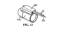
図11〜14は、加圧流体管15を取り付けるための二つの主要構成要素、すなわち図11に一般的に310で示された管状ソケットプローブ、及び図12に一般的に320で示された管保持器を含む、かかる構成を示す。管状ソケットプローブ310は、被験者の手の指または足の指を受けるための中空内部311、及び加圧流体(例えば空気)をプローブの内部区画中に案内するための入口312で終了する流体案内通路を形成されている。前述に加えて、プローブ310は、その上面上に、概略的に315で示されたラッチを一端に持ち、概略的に316で示されたロック要素を反対端に持って形成された取り付け部材314を持つ。
FIGS. 11-14 show two main components for attaching the
図11〜14に示された装置は、電気ヒーター、光学プレチスモグラフ、温度センサなどの電気装置をさらに含むときに特に有用である。かかる場合には、プローブ310は、電気装置のための概略的に317で示された電気接点を含むだろう。同様に、管保持器320はまた、管保持器が一体化リングに付与されるときに電気接点317と係合するために概略的に327で示された電気接点を含むだろう。電気接点327が連結されている電気伝導体は、図12に概略的に321で示されている(図1〜7を含めて19で示されている)。図12はまた、一体化されたリング310内の口312に結合される加圧流体口322、一体化されたリングのラッチ315と共働するラッチング要素325、及び一体化されたリングのロック要素316と係合するロック要素326を概略的に示す。
The apparatus shown in FIGS. 11-14 is particularly useful when it further includes electrical devices such as electric heaters, optical plethysmographs, temperature sensors and the like. In such a case, probe 310 will include an electrical contact indicated generally at 317 for the electrical device. Similarly, the
図11は、空気入口312が硬いわずかに溝付きの突起の形のものであるときのプローブ310を示す。内部凹所内のラッチ315、及び一体化されたリングの反対端のロック要素316は、図12に示された取り外し可能な管取り付け部材320内のそれらの対の片方325及び326とそれぞれ相互作用する。空気入口322は、気密シールを形成するためにプローブ310上の対応する空気入口312に付与されると圧縮されるように設計された弾性材料からなることが好ましく、一方前述のラッチ及びロック要素は、相互作用して、図13に示されるように安定な態様であるが解放可能な態様で二つの部分を固定及びロックする。二つの部分の連結配置のさらなる利点は、流体案内管と同様の電気伝導ワイヤー321が身体表面の上で上昇したような固定されかつ安定な配置で取り付け部材320の端部に固定されることである。
FIG. 11 shows the
図11〜13に示された構成は、最少のオペレーター努力または技術熟練しか必要としない態様で迅速かつ容易に実行される流体案内管及び電気接続を可能にすることがわかるだろう。それはまた、安定かつ気密的な連結を確保し、かつプローブと電気装置の間の電気連通を可能にする電気接続体を提供する。従って、接続は、例えば、上述のように、光学プレチスモグラフの要素に、温度感知手段に、またはプローブ内の加熱コイルになされることができる。同様に、電気接続は、プローブを識別する目的のためにプローブ自体に取り付けられた電子識別装置に対してなされることができる。 It will be appreciated that the configuration shown in FIGS. 11-13 allows fluid guide tubes and electrical connections to be performed quickly and easily in a manner that requires minimal operator effort or skill. It also provides an electrical connection that ensures a stable and airtight connection and allows electrical communication between the probe and the electrical device. Thus, the connection can be made, for example, to an optical plethysmographic element, to temperature sensing means, or to a heating coil in the probe, as described above. Similarly, an electrical connection can be made to an electronic identification device attached to the probe itself for the purpose of identifying the probe.
管とワイヤー取り付け手段の有利な組み合わせは図12及び13に示され、指分離及び管つなぎ手段(例えば図8では20として、図9では120として、図10では220として示される)は図14に示されている。管保持器要素320の末梢端からの身体表面の上への案内管及びワイヤーの複合体の上昇は図12及び13に示されている。
An advantageous combination of tube and wire attachment means is shown in FIGS. 12 and 13, and finger separation and tube splicing means (eg shown as 20 in FIG. 8, as 120 in FIG. 9 and as 220 in FIG. 10) are shown in FIG. It is shown. The elevation of the guide tube and wire complex from the distal end of
例えば、管保持器要素320の末梢端と分離リング420の管保持手段の間の管及びワイヤーの約180°の弧の形成によって、図14で420で示された分離リング420及びプローブが相互作用することができる多数の方法がある。同様に、プローブ分離リング420は、管及びワイヤーの機械的歪、引きずり、または運動によるプローブの機械的摂動のための潜在能力を低下するために、簡単に上述されたように図5及び図6で示された方法で相互作用することができる。
For example, the formation of an approximately 180 ° arc of tube and wire between the distal end of the
図15は、本発明の監視装置のさらなる改善を示し、それは、監視される被験者の身体の指の肢を支持するための肢支持体で具体化されることができる。図15の例示実施態様では、肢支持体は、測定全体を通して被験者の手の前腕及び付け根を支持及び安定化し、かつ肢支持体の前方に指を快適かつ安定的に位置させることを可能にし、それにより患者の動き及び関連した機械的摂動を、従って監視される指が被験者の手の一つ以上の指である場合の外的ノイズを減少するために、一般的に500で示された腕支持体である。 FIG. 15 shows a further improvement of the monitoring device of the present invention, which can be embodied in a limb support for supporting a finger limb of the body of the subject being monitored. In the exemplary embodiment of FIG. 15, the limb support supports and stabilizes the forearm and root of the subject's hand throughout the measurement and allows the finger to be comfortably and stably positioned in front of the limb support; In order to reduce patient movement and associated mechanical perturbation, and thus external noise when the finger being monitored is one or more fingers of the subject's hand, an arm generally indicated at 500 It is a support.
図15に示された前腕支持体は、一般的に上で引用した米国特許第4270235号(それは参考としてここに組み込まれる)に記述されたものと類似しているが、プローブを患者の指に付与する工程時に、図1〜3に対して上述した圧力付与器10を支持するためのプローブ支持凹所510を与えることによって変更されている。従って、図15に示された変更された前腕支持体は、指をプローブ内腔中に挿入してプローブを膨張させて、すなわち加圧する工程時に、指に対して適切な配向で患者の指上への圧力付与器の適切かつ安定な配置を容易にする。
The forearm support shown in FIG. 15 is generally similar to that described in US Pat. No. 4,270,235, cited above, which is incorporated herein by reference, with the probe attached to the patient's finger. During the application step, this is modified by providing a
かかる改善された前腕支持体を図1〜14に対して上述した他の装置と組み合わせて使用することは、個々の装置のいずれかの単独使用より高いレベルのノイズ抑制を提供する。 Using such an improved forearm support in combination with other devices described above with respect to FIGS. 1-14 provides a higher level of noise suppression than any single use of individual devices.
図16は、一般的に600で示されている閉塞カフの別の形を示す。それは、圧力付与器10を担持する指に、それに対して基部側に、すなわち被験者の心臓に面する側に、付与される。この場合、圧力付与器10自体はまた、カフ18(図1)の代りに、閉塞器として作用することができる。
FIG. 16 shows another form of an occlusion cuff, generally designated 600. It is applied to the finger carrying the
血流を完全に閉塞することは通常可能であるけれども、我々は、それでもなお、ほんの一部の場合において、患者の収縮期の血圧よりかなり高いことがありうる極めて高いレベルの閉塞圧であっても、血流を完全に閉塞するためには不十分であることを発見した。これは、血管構造及び組織組成の機能的特性に関連しているかもしれない。かかる場合、残留拍動血液量信号の振幅は、付与された閉塞圧のレベルをさらに高めることによって影響を受けないことが多い。 Although it is usually possible to completely occlude the blood flow, we still have very high levels of occlusion pressure that in some cases can be significantly higher than the patient's systolic blood pressure. Has also found that it is insufficient to completely occlude blood flow. This may be related to the functional properties of vascular structure and tissue composition. In such cases, the amplitude of the residual pulsatile blood volume signal is often unaffected by further increasing the level of applied occlusion pressure.
かかる環境下では、かかる不完全な閉塞の発生を、残留動脈拍動容積の絶対的及び/または相対的大きさ、及び規定された閉塞期間中のこの不完全閉塞の絶対的及び/または相対的期間の両方に関して、識別及び定量することが重要である。 Under such circumstances, the occurrence of such incomplete occlusion may be attributed to the absolute and / or relative magnitude of the residual arterial pulsatile volume and the absolute and / or relative of this incomplete occlusion during a defined occlusion period. It is important to identify and quantify for both time periods.
かかる情報は、試験の有効性のレベルを決定するために非常に重要である。なぜなら乏しい閉塞量は、実際には企図した閉塞によって作られた生理学的刺激度に悪影響を及ぼしうるからである。従って、付与されたカフ圧力の最大許容レベルにもかかわらず、存在する残留拍動信号の大きさを検知して定量する能力は、本願のさらなる改善である。残留検知信号の大きさを決定することは、例えば試験の質を類別し、かつ試験結果を修正するために有用である情報を提供することができる。それはまた、圧力を増加することにより残留動脈脈波度のさらなる減少がない場合でも、閉塞手段によって付与される圧力を限定するために有用であるフィードバックを提供する。上記収縮期圧力レベルの付与にもかかわらず不完全な閉塞の存在は、本質的に有意な診断上の特徴を表わすことができる。かかる装置では、監視プローブは、それぞれの指を通る動脈脈波がないときを示すためにそれぞれの指を通る動脈脈波を監視するために、または完全な閉塞が成し遂げられない場合に、閉塞除去後に得られる信号に付与されるべき、残留信号の大きさに基づく修正係数を作り、従って試験結果を調整するために、効果的である。 Such information is very important to determine the level of test effectiveness. This is because a poor amount of occlusion can actually adversely affect the degree of physiological stimulation created by the intended occlusion. Thus, the ability to detect and quantify the magnitude of the residual pulsation signal present despite the maximum allowable level of applied cuff pressure is a further improvement of the present application. Determining the magnitude of the residual detection signal can provide information that is useful, for example, for categorizing test quality and correcting test results. It also provides feedback that is useful to limit the pressure applied by the occlusion means, even if there is no further decrease in residual arterial pulse rate by increasing the pressure. The presence of incomplete occlusion despite the application of the systolic pressure level can represent an essentially significant diagnostic feature. In such a device, the monitoring probe can remove the occlusion to monitor when there is no arterial pulse wave through each finger or to monitor the arterial pulse wave through each finger or when complete occlusion is not achieved. It is effective to create a correction factor based on the magnitude of the residual signal to be applied to the signal obtained later and thus adjust the test results.
不完全な動脈閉塞の定量分析は、図17の700で示されたように検知された動脈脈信号の絶対的振幅を測定することによって、または閉塞時に図17の705で示されたように検知された動脈脈信号の振幅を、706で示されたように対応する動脈脈信号で、もしくは例えば701または704で示されたように閉塞側のベースライン動脈脈信号の振幅の平均振幅で、割ることによって決定されることができる。従って、得られる比は、それらの値が予め定められた閾値を越えるとき、不完全な動脈閉塞の相対的指数を提供することができる。 Quantitative analysis of incomplete arterial occlusion can be detected by measuring the absolute amplitude of the detected arterial pulse signal as shown at 700 in FIG. 17 or as shown at 705 in FIG. Divide the amplitude of the generated arterial pulse signal by the corresponding arterial pulse signal as shown at 706 or by the average amplitude of the occluded baseline arterial signal as shown at 701 or 704, for example. Can be determined by Thus, the resulting ratio can provide a relative index of incomplete arterial occlusion when those values exceed a predetermined threshold.
同様に、705での動脈脈信号の絶対値は、不完全な動脈閉塞の前記絶対指数の値が予め定められた閾値を越えるときに不完全な動脈閉塞の絶対指数を識別するために使用されることができる。さらに、不完全な動脈閉塞の前記絶対または相対指数は、試験の質を類別するために、かつ試験結果を修正するために使用されることができる。 Similarly, the absolute value of the arterial pulse signal at 705 is used to identify the absolute index of incomplete arterial occlusion when the absolute index value of incomplete arterial occlusion exceeds a predetermined threshold. Can. Further, the absolute or relative index of incomplete arterial occlusion can be used to categorize test quality and to correct test results.
米国特許第6939304号の図16は、閉塞前の動脈脈波信号振幅を血流閉塞の標準期間後の続く相対信号振幅の変化と結合する著しく強力な関係を記載している。この関係は、大きな研究母集団で一貫して観察されており、重要なことに、それは、所定の個々の被験者内の多数の試験を考えるときに一貫して観察され、そこでは閉塞前の信号振幅の著しい変動性が観察されることができ、かかる変動性は生理学的に正常であることを示唆する。図18に示されたように、閉塞後の相対信号振幅の変化は、刺激前の信号振幅に関して指数関数的に反比例することが見出されており、かつ続いてn>1000の多くの試料中で約0.8の著しく高い相関係数を持つことが見出された。本質的に、これは、より低い振幅の閉塞前信号が閉塞の解放後により大きな相対的な増加と関連していることを意味し、逆もまた真である。刺激前の信号振幅は、個人内であっても、正常な生理学的因子によって広く変動することができるので、結果として生じる閉塞後の相対的な信号振幅の変化の変動性はまた、生理学的に正常であると考えられることができる。閉塞後の相対的な信号振幅の変化は内皮機能を示すので、閉塞前のベースライン振幅の生理学的に正常な変動性に関連したその潜在的な不安定性が問題を起こす。なぜなら個人の内皮機能は、少なくとも短期間では安定していると考えられるからである。この問題は、閉塞後応答のこの固有のベースライン振幅依存性に対して修正するために付与される経験的に誘導された相関係数を使用することによって解決されることができる。 FIG. 16 of US Pat. No. 6,939,304 describes a markedly strong relationship that combines arterial pulse wave signal amplitude prior to occlusion with subsequent changes in relative signal amplitude after a standard period of blood flow occlusion. This relationship has been consistently observed in a large study population, and importantly it is consistently observed when considering multiple trials within a given individual subject, where the signal before occlusion Significant variability in amplitude can be observed, suggesting that such variability is physiologically normal. As shown in FIG. 18, the change in relative signal amplitude after occlusion has been found to be exponentially inversely proportional to the signal amplitude before stimulation, and subsequently in many samples where n> 1000. Was found to have a significantly higher correlation coefficient of about 0.8. In essence, this means that lower amplitude pre-occlusion signals are associated with a greater relative increase after the release of the occlusion, and vice versa. Because the signal amplitude before stimulation can vary widely, even within an individual, due to normal physiological factors, the variability of the resulting change in relative signal amplitude after occlusion is also physiologically Can be considered normal. Since the change in relative signal amplitude after occlusion is indicative of endothelial function, its potential instability associated with physiologically normal variability in baseline amplitude prior to occlusion causes problems. This is because an individual's endothelial function is considered stable at least for a short period of time. This problem can be solved by using an empirically derived correlation coefficient that is applied to correct for this inherent baseline amplitude dependence of the post-occlusion response.
かかるベースライン信号振幅に関連した修正係数は米国特許第6939304号に記載されている。それは、ベースライン信号振幅と閉塞後信号振幅変化の間の相関関数に対する本質的に逆関数である。それは、所定のベースライン信号振幅に適用されて修正係数を生じ、基本形:修正係数=a*logベースライン振幅+bであり、ここでベースライン値は、閉塞前信号振幅である。 A correction factor related to such baseline signal amplitude is described in US Pat. No. 6,939,304. It is essentially an inverse function to the correlation function between baseline signal amplitude and post-occlusion signal amplitude change. It is applied to a given baseline signal amplitude to produce a correction factor, basic form: correction factor = a * log baseline amplitude + b, where the baseline value is the pre-occlusion signal amplitude.
本願は、一時的な調整、組織容積、及び修正係数を決定する際に使用された閉塞前ベースライン振幅の修正に関連した血圧に基づく、この修正係数への多数の改善を記載する。 This application describes a number of improvements to this correction factor based on blood pressure associated with the correction of the pre-occlusion baseline amplitude used in determining the temporary adjustment, tissue volume, and correction factor.
手の指及び足の指の動脈は、特に自律神経系活動に反応する。これは、それ自体、一般的に経時的な自発的変化にさらされ、かつ血流閉塞の期間のような有害な刺激に高度に反応する。図18は、同一圧力場が反対側の指上のプローブ内に付与されている間に一つの側上に閉塞圧力場を付与するためにカフが使用されたときの図7に記載された704/701に対応する同時に測定された反応指標を比較する研究の結果を示す。この研究は、40人の被験者からなり、図13に示されるように、801で示された閉塞の終了後の時間の連続30秒の変位に渡る相関関係は一貫して極めて高かった。全ての40人の被験者の主観的印象は、指付与閉塞がカフ付与閉塞より不快さがかなり少ないことであった。従って、プローブ自体内で閉塞を達成することは有利でありうるが、動脈閉塞を作る両手段は効果的かつ臨床的に容認できると考えられる。図19は、手の指容積とベースライン振幅を比較する研究の結果を示し、そこでは男性と女性の関係を示す線901及び902は高度に相関関係があり、直線形でありかつ平行である。
The finger and toe arteries are particularly responsive to autonomic nervous system activity. As such, it is generally subject to spontaneous changes over time and is highly responsive to harmful stimuli such as periods of blood flow obstruction. FIG. 18 shows 704 as described in FIG. 7 when the cuff is used to apply an occlusive pressure field on one side while the same pressure field is applied in the probe on the opposite finger. Results of studies comparing simultaneously measured response indices corresponding to / 701 are shown. This study consisted of 40 subjects and, as shown in FIG. 13, the correlation over a continuous 30 second displacement of time after the end of the occlusion indicated at 801 was consistently very high. The subjective impression of all 40 subjects was that the finger-applied occlusion was significantly less uncomfortable than the cuff-applying occlusion. Thus, although it may be advantageous to achieve occlusion within the probe itself, both means of creating arterial occlusion are considered effective and clinically acceptable. FIG. 19 shows the results of a study comparing hand finger volume and baseline amplitude, where the
従って、閉塞前と閉塞後の期間を比較するとき、この刺激が手の指及び足の指の血管緊張度、従って測定されたベースライン振幅を一時的に変えると期待することは合理的であるだろう。不幸にも、閉塞自体がその余波で閉塞部位に局部的変化を誘発し、信号に大きく影響を及ぼすので、閉塞後の閉塞部位の信号振幅を正確に測定することは不可能である。米国特許第6939304号は、実際の信号振幅が閉塞事象と組み合わされた正常自律神経系関連因子により実質的に影響を受けるという可能性にもかかわらず、修正のための根拠として閉塞された側の未調整閉塞前期間のベースライン振幅を使用することを記載する。 Thus, when comparing pre- and post-occlusion periods, it is reasonable to expect that this stimulus will temporarily alter the finger and toe vascular tone and thus the measured baseline amplitude. right. Unfortunately, the occlusion itself induces local changes in the occlusion site in its aftermath, and greatly affects the signal, so it is impossible to accurately measure the signal amplitude at the occlusion site after occlusion. U.S. Pat. No. 6,939,304 describes the fact that the actual signal amplitude is substantially affected by normal autonomic nervous system-related factors combined with an occlusion event, but the occluded side as the basis for correction. Use of baseline amplitude of unadjusted pre-occlusion period is described.
図17は、特に、閉塞部位のベースライン信号振幅を適切に補償するために、非閉塞部位の(制御)信号の閉塞前に対する閉塞後の変化の比を用いることに基づいて、上述の自律神経媒介変化を評価するためのかかる修正が間接的になされることができる方法を示す。 FIG. 17 illustrates the above-described autonomic nerve based on using the ratio of post-occlusion change to pre-occlusion of the (control) signal of the non-occluded site, particularly to properly compensate the baseline signal amplitude of the occluded site Fig. 4 shows how such a modification to assess mediated changes can be made indirectly.
この方法は以下に説明される:
第一に、図17に一般的に700として示された典型的な試験研究の全体的な時間推移を考えるとき、閉塞部位の応答比は、測定された閉塞後信号振幅704をそのベースライン信号振幅701で割ることによって決定されることができる。同様に、非閉塞部位の応答比は、測定された閉塞後信号振幅703をそのベースライン信号振幅702で割ることによって決定されることができる。閉塞部位の比がその対応するかつ同時に記録された非閉塞部位の応答比で割られるとき、これは図17にAで示される修正比を生じる。
This method is described below:
First, considering the overall time course of a typical test study, generally indicated as 700 in FIG. 17, the response ratio of the occlusion site is obtained by measuring the measured
この修正比に一般形a*log701+b(ここでaとbは定数)の上述のベースライン振幅修正係数を掛けると、図17にBで示されるベースライン振幅修正比を生じる。
Multiplying this correction ratio by the above-described baseline amplitude correction factor of the general form a *
ベースライン振幅修正係数に対して一時的な修正を実現するために、701として示された閉塞部位の閉塞前期間中の関心領域内のベースライン振幅は、一時的に修正されたベースライン振幅を決定するために、制御部位の閉塞前信号振幅(702)で割られた、閉塞されていない(制御)部位の閉塞後信号振幅(703)の比を掛けられることによって、そしてこの値を、一時的に調整されたベースライン修正係数を誘導するためにベースライン修正係数関数中に代入することによって修正されることができる。従って、ベースライン修正係数関数中に代入し(701*(703/702))、そして修正比を掛けると、図17のCに示される一時的に調整されたベースライン振幅修正比を生じる。 In order to achieve a temporary correction to the baseline amplitude correction factor, the baseline amplitude in the region of interest during the pre-occlusion period of the occlusion site indicated as 701 is calculated as the temporarily corrected baseline amplitude. To determine this value by multiplying by the ratio of the non-occluded (control) site post-occlusion signal amplitude (703) divided by the pre-occlusion signal amplitude (702) of the control site and Can be modified by substituting into the baseline correction factor function to derive an automatically adjusted baseline correction factor. Thus, substituting into the baseline correction factor function (701 * (703/702)) and multiplying by the correction ratio results in a temporarily adjusted baseline amplitude correction ratio shown in FIG.
これに代えて、同じ種類の修正が、修正された閉塞側のベースラインが関心時の選ばれた領域の直前の調整された信号振幅を表わすように、関心領域の時間の直前の制御側の閉塞後信号振幅を使用してなされることができる。被験者の群732のための測定された閉塞前の閉塞部位のベースラインデータに対してかかる修正を適用することは、続く閉塞後血管応答に対するその修正を増加した。 Alternatively, the same type of correction may be applied to the control side immediately prior to the time of the region of interest so that the modified occluded baseline represents the adjusted signal amplitude immediately prior to the selected region of interest. This can be done using post-occlusion signal amplitude. Applying such corrections to the measured pre-occlusion site baseline data for group 732 of subjects increased that correction to subsequent post-occlusion vascular responses.
例えば、閉塞前の閉塞部位のベースライン振幅701の対数、及び修正比すなわち(704/701)/(703/702)間の線形回帰相関係数は、0.755であり、一方803/802の比を掛けられることによって修正された後の閉塞側の閉塞前振幅(701)に対する相関は、0.848であることが見出された。
For example, the logarithm of the
米国特許第6939304号に記載されたベースライン振幅修正係数のさらなる欠点は、それが誘導される手の指の実際の組織容積を考慮に入れていないことである。これは、信号振幅/閉塞後の応答関係を考えるときに重要である。従って、重要であるのは、信号のサイズ自体よりむしろ、刺激が付与される血管緊張度のレベルである。血管緊張度は、血管抵抗の相対的度合によって決定され、それは、信号振幅が誘導される組織容積に対して正規化された信号振幅に関連する。手の指の寸法は、人ごとに実質的に変わり、かつ同じ手の指間で(例えば親指対小指)さえ変わり、これは、上述したベースライン振幅修正関数の精度に影響すると予想される。図19は、実際の手の指の周囲の測定に基づいた手の指の容積の末梢指骨の推定された容積の所定の間隔範囲と関連した平均ベースライン振幅の値を示し、901は男性母集団を表わし、902は女性母集団を表わし、それぞれの線の最良適合(最小自乗法)及びそれぞれの線形回帰係数と共に表わす。プロットは、手の指寸法に対する信号ベースライン振幅の直線性(図17の701に対応する)並びに推定された容積間隔によって群分けされた1959人の男性と1266人の女性の母集団に基づいた、手の指の寸法の範囲の両方を証明する。また、所定の手の指容積の女性に比べて男性がより大きな振幅を持つという性関連の片寄りがあるように見える。それは、生理学的因子または解剖学的因子に関連するかもしれない。 A further disadvantage of the baseline amplitude correction factor described in US Pat. No. 6,939,304 is that it does not take into account the actual tissue volume of the finger of the hand from which it is derived. This is important when considering the signal amplitude / post-occlusion response relationship. Therefore, what is important is the level of vascular tone at which the stimulus is applied, rather than the size of the signal itself. Vascular tone is determined by the relative degree of vascular resistance, which is related to the signal amplitude normalized to the tissue volume from which the signal amplitude is derived. Hand finger dimensions vary substantially from person to person, and even between fingers of the same hand (eg, thumb vs. little finger), which is expected to affect the accuracy of the baseline amplitude correction function described above. FIG. 19 shows the mean baseline amplitude value associated with a predetermined interval range of the estimated volume of the peripheral phalange of the finger volume based on measurements around the actual hand finger, 901 is the male mother Represents the population, 902 represents the female population, with the best fit (least squares) of each line and the respective linear regression coefficients. The plot was based on a population of 1959 men and 1266 women grouped by linearity of signal baseline amplitude to hand finger size (corresponding to 701 in FIG. 17) and estimated volume spacing. Prove both the range of hand finger dimensions. It also appears that there is a gender-related offset in which men have a greater amplitude than women with a finger volume of a given hand. It may be related to physiological or anatomical factors.
ベースライン信号振幅が、上に規定される一時的遅延のために修正されたとき、及び基準組織容積値で割られた測定された組織容積自体でベースライン信号振幅を割ることによってさらに正規化されたとき、修正比すなわち(704/701)/(703/702)に対するその続く相関関係は0.8550に高められた。 The baseline signal amplitude is further normalized by dividing the baseline signal amplitude by the measured tissue volume itself divided by the temporal delay as defined above and by the reference tissue volume value. The subsequent correlation to the correction ratio, ie (704/701) / (703/702), was increased to 0.8550.
上述の組織容積に基づいた不正確な源に対して指の組織容積を決定することは、測定された信号を実際の手の指寸法に対して正規化することによって解決されることができた。組織容積を定量的に決定するための自動化法は米国特許第7819811号に記載されている。しかし、この測定を実施するためのその方法は、装置に対する主要な変化を要求する。図18は、同一圧力場が反対側の指上のプローブ内に付与されている間に一つの側上に閉塞圧力場を付与するためにカフが使用されたときの図17に記載された704/701に対応する同時に測定された反応指標を比較する研究の結果を示す。この研究は、40人の被験者からなり、図18に示されるように、711で示された閉塞の終了後の時間の連続30秒の変位に渡る相関関係は一貫して極めて高かった。全ての40人の被験者の主観的印象は、指付与閉塞がカフ付与閉塞より不快さがかなり少ないことであった。従って、プローブ自体内で閉塞を達成することは有利でありうるが、動脈閉塞を作る両手段は効果的かつ臨床的に容認できると考えられる。 Determining the finger tissue volume against an inaccurate source based on the tissue volume described above could be solved by normalizing the measured signal to the actual finger size of the hand. . An automated method for quantitative determination of tissue volume is described in US Pat. However, the method for performing this measurement requires major changes to the device. FIG. 18 illustrates 704 as described in FIG. 17 when a cuff is used to apply an occlusive pressure field on one side while the same pressure field is applied in the probe on the opposite finger. Results of studies comparing simultaneously measured response indices corresponding to / 701 are shown. This study consisted of 40 subjects, and the correlation over a continuous 30 second displacement of time after the end of the occlusion indicated at 711 was consistently very high, as shown in FIG. The subjective impression of all 40 subjects was that the finger-applied occlusion was significantly less uncomfortable than the cuff-applying occlusion. Thus, although it may be advantageous to achieve occlusion within the probe itself, both means of creating arterial occlusion are considered effective and clinically acceptable.
図20は、指の末梢端の容積に基づいて修正されたベースライン修正係数を生成するために指の末梢端の寸法を測定するための、一般的に800で示された指寸法測定装置を示す。図20に示されるように、装置800は、指を受け入れるための開口802を形成された指受け入れ部材801を含む。部材801は、側部表面804および805を含む別の部材803に沿ってスライドすることができ、前記側部表面804および805は、鋭角で交差し、部材801内に受け入れられる指の外側表面によって係合される。部材803は、表面804に沿って目盛りをさらに形成されている。目盛り806は、指が部材803に沿って指の外側表面が部材803の両表面804および805と接触するまで移動されたときに、指の寸法、およびそれによって指の容積を示すように設定されている。目盛りは、部材801の側壁中に形成された窓807を通して見られることができる。
FIG. 20 illustrates a finger dimension measuring device, generally designated 800, for measuring the dimension of the distal end of the finger to generate a corrected baseline correction factor based on the volume of the distal end of the finger. Show. As shown in FIG. 20, the
図20に示されている設計は、手の指の末端先端に関して手の指の長さの所定の領域で手の指の寸法を測定するための一つの簡単な手段を示す役割を有するにすぎない。他の多数の手段がこの目的のために使用されることができる。これらは、巻尺を使用した指の周囲長さの直接測定や、指領域が入ることのできる最小寸法を決定するための変化する寸法の一連の穴を含むが、これらに限定されない。 The design shown in FIG. 20 only serves to represent one simple means for measuring hand finger dimensions in a given region of hand finger length with respect to the distal end of the hand finger. Absent. Numerous other means can be used for this purpose. These include, but are not limited to, direct measurement of finger circumference using a tape measure and a series of holes of varying dimensions to determine the smallest dimension that a finger area can enter.
ベースライン信号振幅を調整するための別の代替的なアプローチは、信号振幅を被験者の身体表面面積(BSA)に対して正規化することである。被験者のBSAはそれ自体、基準BSA値で割られ、基準BSA値は、周知の公式を使用して被験者の身長および体重から誘導されることができる。これは、手の指の組織容積と有意に相関するので、図17のDに示される態様でベースライン信号振幅の正規化を助けるために容積の代用として使用されることができる。 Another alternative approach for adjusting the baseline signal amplitude is to normalize the signal amplitude to the subject's body surface area (BSA). The subject's BSA is itself divided by the reference BSA value, which can be derived from the subject's height and weight using well-known formulas. Since this correlates significantly with the finger finger tissue volume, it can be used as a volume substitute to help normalize the baseline signal amplitude in the manner shown in FIG. 17D.
例示的なものにすぎない上述の例は、我々の米国特許第7819811号に記載の容積の正確な決定とは対照的に手の指の寸法の代用指標を与えるだろうが、簡単に適用できるという利点を有するだろう。 The above example, which is only exemplary, will give a surrogate measure of hand finger size as opposed to an accurate determination of volume as described in our US Pat. No. 7819811, but is easily applicable Would have the advantage.
組織容積に基づく信号振幅の修正と同様に、患者の脈圧力の範囲(これは、収縮期の全身血圧と拡張期の全身血圧との差である)に関してベースライン信号振幅を修正することも有利でありうる。脈圧力は、生じる信号振幅を決定するために有効動脈抵抗のレベルと協調して作用する。 As well as signal amplitude correction based on tissue volume, it is also advantageous to correct the baseline signal amplitude with respect to the patient's pulse pressure range (which is the difference between systolic and diastolic systemic blood pressure). It can be. The pulse pressure acts in concert with the level of effective arterial resistance to determine the resulting signal amplitude.
脈圧力の大きさについて信号振幅を修正することが有利である理由は、初期信号振幅と閉塞後応答との間の相互作用を考慮すると、本当に重要なことは、信号の寸法それ自体よりもむしろ、刺激が付与されている血管の緊張度のレベルであるからである。被験者の脈圧力の大きさは、心臓の作用と全身抵抗全体との組み合わせから誘導されるので、それは、考慮されている特定の測定部位の局所的血管抵抗から大きな程度で独立している。従って、局所化された血管緊張度の所定のレベルでの脈圧力の変動は、信号振幅の実質的な変動を生じることができ、これは、ベースライン振幅の決定精度に影響を与えると予測されることができる。従って、大きな脈圧力を有する被験者は、低レベルの動脈緊張度を示すと予測され、従って、同じ信号振幅を有するが小さな脈圧力を有する被験者と比較して、血管拡張について大きな能力を示すと予測されるだろう。 The reason why it is advantageous to modify the signal amplitude for the magnitude of the pulse pressure is that, considering the interaction between the initial signal amplitude and the post-occlusion response, what is really important is rather than the signal size itself This is because the level of the tension of the blood vessel to which the stimulus is applied. Since the magnitude of the subject's pulse pressure is derived from a combination of cardiac action and overall systemic resistance, it is to a large extent independent of the local vascular resistance at the particular measurement site being considered. Thus, fluctuations in pulse pressure at a given level of localized vascular tone can result in substantial fluctuations in signal amplitude, which is expected to affect the accuracy of determining baseline amplitude. Can. Thus, subjects with large pulse pressure are predicted to exhibit a low level of arterial tone and are therefore predicted to exhibit greater capacity for vasodilation compared to subjects with the same signal amplitude but with small pulse pressure. Will be done.
従って、ベースライン信号振幅を正規化する方法は、図17のEに示されるように基準脈圧力値に対する患者の脈圧力の比によって、測定されたベースライン信号振幅を修正することに基づくだろう。 Thus, a method for normalizing the baseline signal amplitude would be based on correcting the measured baseline signal amplitude by the ratio of the patient's pulse pressure to the reference pulse pressure value as shown in FIG. 17E. .
診断能力を改良するために有用であることが予測せぬことに見出された別の分析特徴は、図17のA,B,C,D及びEに記載される応答指数に対して対数変換を適用するものである。応答指数の対数を使用することは、患者と非選択母集団との間で、対応する従来の指数よりも良好な分離を与えることが経験的に証明されている。それは、非対称性の少ない頻度分布プロフィールを与えるため、統計学的にも好適な変化であるように見えるだろう。 Another analytical feature that was unexpectedly found to be useful for improving diagnostic capabilities is a logarithmic transformation to the response index described in FIG. 17A, B, C, D and E. Is applied. Using the logarithm of the response index has been empirically proven to give a better separation between the patient and the unselected population than the corresponding conventional index. It will appear to be a statistically favorable change because it gives a frequency distribution profile with less asymmetry.
「増加指数」は、動脈の剛さの一般的なレベルを反映するパラメータを与えるために、非侵襲的に測定された脈波形を使用する周知の指数であり、その増大は、とりわけ、動脈の老化および動脈硬化の結果である。脈波形は、入射中央動脈圧力が脈波の波反射とのその合計によって変化される度合いによって影響を受ける。老化および疾患過程による動脈壁の変性は、動脈壁の硬化および脈波速度の増大を生じ、これらは、入射波および反射波が合計される態様に影響を与える。 An “increase index” is a well-known index that uses a non-invasively measured pulse waveform to give a parameter that reflects the general level of arterial stiffness, and the increase is, among other things, an arterial It is the result of aging and arteriosclerosis. The pulse waveform is affected by the degree to which the incident central arterial pressure is changed by its sum with the wave reflection of the pulse wave. Degeneration of the arterial wall due to aging and disease processes results in stiffening of the arterial wall and an increase in pulse wave velocity, which affects the manner in which incident and reflected waves are summed.
PATプローブは、この指数を測定するために特異的に有利な測定環境を与える。これは、測定を静脈血混合なしに動脈脈波のみに限定しながら、測定部位が反射血管変化を誘導しうる誘導静脈貯留によって影響を受けないことをさらに確保するPATプローブの能力によるものである。それはさらに、例えば米国特許第6319205号にかなり詳細に記述されているように、最適な経壁圧力の状態が測定のために適用されて動脈壁の緊張を最適に緩和し、それによって最適な範囲の血管の動きおよび信号の線形性を与えることを確保する。従って、PAT装置および方法を使用することは、増加指数の正確で一貫した測定を容易にする。 The PAT probe provides a particularly advantageous measurement environment for measuring this index. This is due to the ability of the PAT probe to further ensure that the measurement site is not affected by induced venous retention that can induce reflex vascular changes while limiting the measurement to only arterial pulse waves without venous blood mixing. . In addition, as described in considerable detail in, for example, US Pat. No. 6,319,205, an optimal transmural pressure condition is applied for measurement to optimally relieve arterial wall tension and thereby an optimal range. Ensure that the blood vessel movement and signal linearity is given. Thus, using the PAT apparatus and method facilitates accurate and consistent measurement of the increase index.
本発明の多くの他の変形、変更及び適用は、当業者には明らかであるだろう。 Many other variations, modifications and applications of the invention will be apparent to those skilled in the art.
Claims (25)
前記被験者の肢のプローブ受け入れ指に付与するためのプローブであって、その中の前記動脈脈波からの信号を測定するためのプローブと、
前記プローブに取り付け可能な流体案内供給管と、
前記肢の支持指の上に受け入れ可能である分離リングであって、前記供給管をそこに固定して支持するように構成された分離リングと
を含み、
前記分離リングは、前記プローブ受け入れ指に隣接する少なくとも一つの指から前記プローブを遠ざけて、それらの間の接触を防止するように寸法決定されており、
前記分離リングは、介在隙間を持つ、複数の長手方向に延びる、周囲に間隔を置かれた突起を持って形成されている内部表面を有し、
前記突起は、前記供給管を前記支持指の上に支持するために十分な弾性を有し、かつ静脈及び動脈血液の両方の流れが前記支持指において悪影響されないことを確保するために十分低いレベルの局所化された力を付与するように構成されていることを特徴とする装置。 A device for monitoring a subject's arterial pulse wave, the device comprising:
A probe for applying to a probe receiving finger of the subject's limb, and a probe for measuring a signal from the arterial pulse wave therein;
A fluid guide supply tube attachable to the probe;
A separation ring that is receptive on a support finger of the limb, the separation ring configured to securely support the supply tube therewith,
The separation ring is dimensioned to move the probe away from at least one finger adjacent to the probe receiving finger to prevent contact therebetween;
The separation ring has an inner surface formed with a plurality of longitudinally extending, circumferentially spaced protrusions with intervening gaps;
The protrusion is sufficiently elastic to support the supply tube over the support finger and low enough to ensure that both venous and arterial blood flow is not adversely affected in the support finger. An apparatus configured to apply a localized force of.
二つの管状ソケットプローブのそれぞれの中に、前記被験者のそれぞれのプローブ受け入れ指の少なくとも末梢指骨を、その先端を含めて挿入すること、
少なくとも一つの分離リングを、それぞれの支持指に、前記プローブ受け入れ指のそれぞれが支持指に隣接するように付与すること、ただし、前記付与することは、前記少なくとも一つの分離リングに、前記管状ソケットプローブの一つから通じる流体供給管を取り付けることを含む、
静圧場を、前記少なくとも末梢指骨のそれぞれに付与すること、
中断された閉塞圧力場を、前記プローブ受け入れ指のうちの一つの先端と前記被験者の心臓の間の領域に付与すること、及び
前記プローブ受け入れ指からの前記動脈脈波を測定すること
を含み、
前記少なくとも一つの分離リングは、前記供給管を前記支持指の上に支持するために十分な弾性を有し、かつ静脈及び動脈血液の両方の流れが前記支持指において悪影響されないことを確保するために十分低いレベルの局所化された力を付与するように構成されていることを特徴とする方法。 A method for monitoring a subject's arterial pulse wave, the method comprising:
Inserting into each of the two tubular socket probes at least the distal phalange of each probe receiving finger of the subject, including its tip,
Applying at least one separating ring to each supporting finger such that each of said probe receiving fingers is adjacent to said supporting finger, wherein said applying to said at least one separating ring, said tubular socket Including attaching a fluid supply tube leading from one of the probes,
Applying a static pressure field to each of the at least peripheral phalanges;
Applying an interrupted occlusion pressure field to a region between the tip of one of the probe-receiving fingers and the subject's heart; and measuring the arterial pulse wave from the probe-receiving finger;
The at least one separation ring is sufficiently elastic to support the supply tube over the support finger and to ensure that both venous and arterial blood flows are not adversely affected at the support finger. Characterized in that it is configured to impart a sufficiently low level of localized force.
Applications Claiming Priority (3)
| Application Number | Priority Date | Filing Date | Title |
|---|---|---|---|
| US201161563574P | 2011-11-24 | 2011-11-24 | |
| US61/563,574 | 2011-11-24 | ||
| PCT/IL2012/050466 WO2013076722A1 (en) | 2011-11-24 | 2012-11-20 | Apparatus for monitoring arterial pulse waves in diagnosing various medical conditions |
Publications (3)
| Publication Number | Publication Date |
|---|---|
| JP2015501696A JP2015501696A (en) | 2015-01-19 |
| JP2015501696A5 JP2015501696A5 (en) | 2016-01-07 |
| JP6134729B2 true JP6134729B2 (en) | 2017-05-24 |
Family
ID=48469239
Family Applications (1)
| Application Number | Title | Priority Date | Filing Date |
|---|---|---|---|
| JP2014542995A Expired - Fee Related JP6134729B2 (en) | 2011-11-24 | 2012-11-20 | Device for monitoring arterial pulse waves in diagnosing various medical conditions |
Country Status (3)
| Country | Link |
|---|---|
| US (1) | US10842395B2 (en) |
| JP (1) | JP6134729B2 (en) |
| WO (1) | WO2013076722A1 (en) |
Families Citing this family (6)
| Publication number | Priority date | Publication date | Assignee | Title |
|---|---|---|---|---|
| CA2580399C (en) | 2004-09-15 | 2015-07-07 | Itamar Medical Ltd. | Method and apparatus for non-invasively measuring physiological parameters, particularly blood flow and venous capacitance |
| US10842395B2 (en) | 2011-11-24 | 2020-11-24 | Itamar Medical Ltd. | Apparatus for monitoring arterial pulse waves in diagnosing various medical conditions |
| JP2019514603A (en) | 2016-05-09 | 2019-06-06 | ベルン テクノロジー カンパニー リミテッドBelun Technology Company Limited | Wearable device for healthcare and method therefor |
| CN109414195B (en) * | 2016-07-08 | 2022-08-26 | 皇家飞利浦有限公司 | Device and method for measuring physiological parameters of a human limb |
| CN109414196B (en) * | 2016-07-08 | 2021-12-14 | 皇家飞利浦有限公司 | Device and method for measuring physiological parameters of a human limb |
| JP6621452B2 (en) * | 2017-09-21 | 2019-12-18 | 日本電信電話株式会社 | Concentration ratio estimation apparatus, concentration ratio estimation method, and program |
Family Cites Families (89)
| Publication number | Priority date | Publication date | Assignee | Title |
|---|---|---|---|---|
| US2438901A (en) | 1944-07-19 | 1948-04-06 | Charles D Coxe | Oriented polymeric sheath |
| US3104661A (en) | 1959-12-14 | 1963-09-24 | Beckman Instruments Inc | System for continuous blood pressure determination |
| US3156237A (en) | 1963-03-08 | 1964-11-10 | Physio Control Company Inc | Apparatus for measuring blood pressure and heartbeat pulses |
| US3168095A (en) * | 1963-03-20 | 1965-02-02 | Medi Plastix Co Inc | Digital separator |
| US3482565A (en) | 1964-03-24 | 1969-12-09 | Carter Wallace | Digital blood pressure measuring device |
| JPS5033676A (en) | 1973-07-30 | 1975-03-31 | ||
| US4030485A (en) | 1974-11-12 | 1977-06-21 | Glenfield Warner | Method and apparatus for continuously monitoring systolic blood pressure |
| US4134396A (en) | 1977-05-23 | 1979-01-16 | Doll Research, Inc. | Method and apparatus for developing intermittent venous blood flow and measuring total blood flow |
| US4112491A (en) | 1977-07-05 | 1978-09-05 | Life Sciences, Inc. | Direct readout real time physiological parameter analog computer |
| JPS5441584A (en) | 1977-09-07 | 1979-04-02 | Asahi Medical Co | Human body blood current meter |
| DE3068203D1 (en) | 1979-08-28 | 1984-07-19 | Battelle Memorial Institute | Apparatus for measuring the human being's blood pressure |
| US4331154A (en) | 1979-10-15 | 1982-05-25 | Tech Engineering & Design | Blood pressure and heart rate measuring watch |
| NL8005145A (en) | 1980-09-12 | 1982-04-01 | Tno | DEVICE FOR INDIRECT, NON-INVASIVE, CONTINUOUS MEASUREMENT OF BLOOD PRESSURE. |
| US4515166A (en) | 1983-06-13 | 1985-05-07 | Dacomed Corporation | Nocturnal penile tumescence and rigidity monitor |
| US4548211A (en) | 1984-01-12 | 1985-10-22 | Marks Lloyd A | Computer assisted admittance plethysmograph |
| US4677984A (en) | 1984-09-24 | 1987-07-07 | Bomed Medical Manufacturing, Ltd. | Calibrated arterial pressure measurement device |
| US4664651A (en) | 1985-03-01 | 1987-05-12 | The Procter & Gamble Company | Subatmospheric method and apparatus for expanding blood vessels to facilitate puncture with a cannula |
| DE3612532A1 (en) | 1985-04-12 | 1986-10-23 | Omron Tateisi Electronics Co., Kyoto | ELECTRONIC BLOOD PRESSURE MEASURING DEVICE |
| JPS61234841A (en) * | 1985-04-12 | 1986-10-20 | オムロン株式会社 | Digital electronic hemomanometer |
| US4685464A (en) | 1985-07-05 | 1987-08-11 | Nellcor Incorporated | Durable sensor for detecting optical pulses |
| GB8524473D0 (en) | 1985-10-04 | 1985-11-06 | Loughborough Consult Ltd | Making measurements on body |
| US4848361A (en) | 1986-01-22 | 1989-07-18 | Dacomed Corporation | Nocturnal penile tumescence and rigidity monitor with removable loops |
| JPS6323645A (en) | 1986-05-27 | 1988-01-30 | 住友電気工業株式会社 | Reflection heating type oxymeter |
| SE456080B (en) | 1987-01-15 | 1988-09-05 | Rexinell Ab | DEVICE FOR CLOSING CONTAINERS |
| US4821734A (en) | 1987-04-21 | 1989-04-18 | Nihon Seimitsu Sokki Co., Ltd. | Sphygmomanometer |
| US5218966A (en) * | 1987-06-12 | 1993-06-15 | Omron Tateisi Electronics Co. | Electronic blood pressure meter |
| US4846189A (en) | 1987-06-29 | 1989-07-11 | Shuxing Sun | Noncontactive arterial blood pressure monitor and measuring method |
| US4836219A (en) | 1987-07-08 | 1989-06-06 | President & Fellows Of Harvard College | Electronic sleep monitor headgear |
| DE3723881A1 (en) | 1987-07-18 | 1989-01-26 | Nicolay Gmbh | METHOD FOR DETERMINING THE OXYGEN SATURATION OF THE BLOOD OF A LIVING ORGANISM AND ELECTRONIC CIRCUIT, AND DEVICE FOR CARRYING OUT THIS METHOD |
| US4860759A (en) | 1987-09-08 | 1989-08-29 | Criticare Systems, Inc. | Vital signs monitor |
| JPH0288041A (en) | 1988-09-24 | 1990-03-28 | Misawahoomu Sogo Kenkyusho:Kk | Finger tip pulse wave sensor |
| US4967758A (en) | 1988-12-08 | 1990-11-06 | Prospect Holdings, Inc. | Disposable cover/liner for blood pressure measuring devices |
| US5111817A (en) | 1988-12-29 | 1992-05-12 | Medical Physics, Inc. | Noninvasive system and method for enhanced arterial oxygen saturation determination and arterial blood pressure monitoring |
| JPH0341926A (en) | 1989-07-07 | 1991-02-22 | Matsushita Electric Works Ltd | Detector for change in sleeping state and sleeping state controller |
| DE69029152T2 (en) | 1990-02-15 | 1997-03-06 | Hewlett Packard Gmbh | Procedure for the non-invasive measurement of oxygen saturation |
| DE69119306D1 (en) | 1990-07-03 | 1996-06-13 | Ueda Electronic Works Ltd | Sphygmomanometer |
| US5179956A (en) | 1990-07-06 | 1993-01-19 | Colin Electronics Co., Ltd. | Contact pressure sensor |
| US5140990A (en) | 1990-09-06 | 1992-08-25 | Spacelabs, Inc. | Method of measuring blood pressure with a photoplethysmograph |
| JP2524278Y2 (en) | 1990-09-10 | 1997-01-29 | コーリン電子株式会社 | Pulse wave detector |
| JP2928410B2 (en) | 1991-09-02 | 1999-08-03 | 花王株式会社 | Cleaning sheet and manufacturing method thereof |
| IL100080A (en) | 1991-11-19 | 1994-12-29 | Sleep Disorders Diagnostic And | Monitor system for determining the sleep stages of a person |
| US5253645A (en) | 1991-12-13 | 1993-10-19 | Critikon, Inc. | Method of producing an audible alarm in a blood pressure and pulse oximeter monitor |
| US5542421A (en) | 1992-07-31 | 1996-08-06 | Frederick Erdman Association | Method and apparatus for cardiovascular diagnosis |
| US5365924A (en) | 1992-07-31 | 1994-11-22 | Frederick Erdman Association | Method and apparatus for non-invasive cardiovascular diagnosis |
| US6342039B1 (en) | 1992-08-19 | 2002-01-29 | Lawrence A. Lynn | Microprocessor system for the simplified diagnosis of sleep apnea |
| AU5016593A (en) | 1992-08-19 | 1994-03-15 | Lawrence A. Lynn | Apparatus for the diagnosis of sleep apnea |
| US6223064B1 (en) | 1992-08-19 | 2001-04-24 | Lawrence A. Lynn | Microprocessor system for the simplified diagnosis of sleep apnea |
| US5337744A (en) | 1993-07-14 | 1994-08-16 | Masimo Corporation | Low noise finger cot probe |
| US5452717A (en) | 1993-07-14 | 1995-09-26 | Masimo Corporation | Finger-cot probe |
| US5438986A (en) | 1993-12-14 | 1995-08-08 | Criticare Systems, Inc. | Optical sensor |
| US5620001A (en) | 1994-04-26 | 1997-04-15 | Byrd; Timothy N. | Universal blood-pressure cuff cover |
| US5566677A (en) | 1994-08-04 | 1996-10-22 | Raines; Jeffrey K. | Calibration of segmental blood changes in arteries and veins during detection of atherosclerosis |
| EP0743014A1 (en) | 1995-05-19 | 1996-11-20 | Unilever N.V. | Edible fat product |
| US5638816A (en) | 1995-06-07 | 1997-06-17 | Masimo Corporation | Active pulse blood constituent monitoring |
| US5669390A (en) | 1995-11-30 | 1997-09-23 | Mccormick; David A. | Single use protective barrier medical accessory for isolating a sphygmomanometer cuff from a patient |
| JP3580924B2 (en) | 1995-12-22 | 2004-10-27 | コーリンメディカルテクノロジー株式会社 | Arterial elasticity evaluation device |
| US5740943A (en) | 1996-03-04 | 1998-04-21 | Shields; Jack W. | Sterile biased cot and examination glove dispensers |
| IL118854A0 (en) | 1996-07-15 | 1996-10-31 | Atlas Dan | Personal micro-monitoring and alerting device for sleepiness |
| IL120881A (en) | 1996-07-30 | 2002-09-12 | It M R Medic L Cm 1997 Ltd | Method and apparatus for the non-invasive continous monitoring of peripheral arterial tone |
| DE19632263C1 (en) | 1996-08-09 | 1998-01-08 | Domed Medizintechnik Gmbh | Method and device for venous compression plethysmography |
| US6343223B1 (en) | 1997-07-30 | 2002-01-29 | Mallinckrodt Inc. | Oximeter sensor with offset emitters and detector and heating device |
| US6115621A (en) | 1997-07-30 | 2000-09-05 | Nellcor Puritan Bennett Incorporated | Oximetry sensor with offset emitters and detector |
| US6179159B1 (en) | 1998-01-26 | 2001-01-30 | Mariruth D. Gurley | Communicable disease barrier digit cover and dispensing package therefor |
| IL124787A0 (en) | 1998-06-07 | 1999-01-26 | Itamar Medical C M 1997 Ltd | Pressure applicator devices particularly useful for non-invasive detection of medical conditions |
| JP3890760B2 (en) | 1998-08-04 | 2007-03-07 | オムロンヘルスケア株式会社 | Pressure band for blood pressure measurement |
| US6152881A (en) | 1999-03-29 | 2000-11-28 | Vasocor, Inc. | Calibrated measurement of blood vessels and endothelium after reactive hyperemia and method therefor |
| WO2000074551A2 (en) | 1999-06-02 | 2000-12-14 | Itamar Medical (Cm) 1997 Ltd. | Diagnosing medical conditions by monitoring peripheral arterial tone |
| US6120459A (en) | 1999-06-09 | 2000-09-19 | Nitzan; Meir | Method and device for arterial blood pressure measurement |
| IL130939A (en) | 1999-07-14 | 2005-11-20 | Itamar Medical Ltd | Probe devices particularly useful for non-invasivedetection of medical conditions |
| US6162188A (en) | 1999-08-16 | 2000-12-19 | Meduck Ltd. | Penile tumescence and rigidity monitoring device |
| US6622034B1 (en) | 1999-09-10 | 2003-09-16 | Imagenix, Inc. | Oximeter sensor with functional liner |
| NZ521115A (en) | 2000-03-02 | 2004-05-28 | Itamar Medical Ltd | Method and apparatus for the non-invasive detection of particular sleep-state conditions by monitoring the peripheral vascular system |
| US7806831B2 (en) | 2000-03-02 | 2010-10-05 | Itamar Medical Ltd. | Method and apparatus for the non-invasive detection of particular sleep-state conditions by monitoring the peripheral vascular system |
| US6338719B1 (en) | 2000-06-12 | 2002-01-15 | Rutgers, The State University Of New Jersey | Method and system for detecting vascular conditions using an occlusive arm cuff plethysmograph |
| AU9291901A (en) | 2000-09-21 | 2002-04-02 | Univ Virginia Commonwealth | Methods for monitoring and optimizing central venuous pressures and intravascular volume |
| US6819950B2 (en) | 2000-10-06 | 2004-11-16 | Alexander K. Mills | Method for noninvasive continuous determination of physiologic characteristics |
| CA2424389C (en) | 2000-10-23 | 2011-07-12 | Itamar Medical Ltd. | Method and apparatus for non-invasively evaluating endothelial activity in a patient |
| US6654628B1 (en) | 2000-11-03 | 2003-11-25 | The Johns Hopkins University | Methods to assess vascular endothelial function |
| WO2002073948A2 (en) | 2001-03-14 | 2002-09-19 | Technion Research And Development Foundation Ltd. | A memory-free method of region filling |
| US6898451B2 (en) | 2001-03-21 | 2005-05-24 | Minformed, L.L.C. | Non-invasive blood analyte measuring system and method utilizing optical absorption |
| US7374540B2 (en) | 2001-04-05 | 2008-05-20 | Itamar Medical Ltd. | Non-invasive probe for detecting medical conditions |
| US7118534B2 (en) | 2001-09-21 | 2006-10-10 | Virginia Commonwealth University | Methods for monitoring and optimizing central venous pressure and intravascular volume |
| JP3632014B2 (en) | 2002-05-14 | 2005-03-23 | コーリンメディカルテクノロジー株式会社 | Endothelial function evaluation device |
| US7819811B2 (en) | 2002-11-06 | 2010-10-26 | Itamar Medical Ltd. | Detecting medical conditions with noninvasive body probes |
| AT412613B (en) | 2003-04-01 | 2005-05-25 | Cnsystems Medizintechnik Gmbh | DEVICE AND METHOD FOR CONTINUOUS, NON-INVASIVE MEASUREMENT OF BLOOD PRESSURE |
| CA2580399C (en) | 2004-09-15 | 2015-07-07 | Itamar Medical Ltd. | Method and apparatus for non-invasively measuring physiological parameters, particularly blood flow and venous capacitance |
| JP5039123B2 (en) | 2007-02-28 | 2012-10-03 | 北海道公立大学法人 札幌医科大学 | Finger artery elasticity measurement program, finger artery elasticity measurement device, and finger artery elasticity measurement method |
| US10154790B2 (en) * | 2007-08-21 | 2018-12-18 | University College Dublin, National University Of Ireland | Method and system for monitoring sleep |
| US10842395B2 (en) | 2011-11-24 | 2020-11-24 | Itamar Medical Ltd. | Apparatus for monitoring arterial pulse waves in diagnosing various medical conditions |
-
2012
- 2012-11-20 US US14/360,635 patent/US10842395B2/en active Active
- 2012-11-20 WO PCT/IL2012/050466 patent/WO2013076722A1/en active Application Filing
- 2012-11-20 JP JP2014542995A patent/JP6134729B2/en not_active Expired - Fee Related
Also Published As
| Publication number | Publication date |
|---|---|
| US20140336517A1 (en) | 2014-11-13 |
| JP2015501696A (en) | 2015-01-19 |
| WO2013076722A1 (en) | 2013-05-30 |
| US10842395B2 (en) | 2020-11-24 |
Similar Documents
| Publication | Publication Date | Title |
|---|---|---|
| JP6134729B2 (en) | Device for monitoring arterial pulse waves in diagnosing various medical conditions | |
| US6331162B1 (en) | Pulse wave velocity measuring device | |
| US11583191B2 (en) | Apparatus and method for determining blood pressure of a subject | |
| US6120459A (en) | Method and device for arterial blood pressure measurement | |
| JP5408751B2 (en) | Autonomic nerve function measuring device | |
| JP5829123B2 (en) | System and method for determining blood flow | |
| US9414755B2 (en) | Method for estimating a central pressure waveform obtained with a blood pressure cuff | |
| JP7191093B2 (en) | Methods for non-invasively determining at least one blood pressure value, measuring devices and systems for non-invasively determining blood pressure | |
| EP1344489A1 (en) | Continuous, non-invasive technique for measuring blood pressure using impedance plethysmography | |
| JP2007527773A (en) | Method and apparatus for optical detection of mixed venous and arterial pulsations in tissue | |
| US20160166157A1 (en) | Methods And Apparatus For Assessing Vascular Health | |
| JP2004521660A (en) | Method and apparatus for assessing hemodynamic parameters and vascular position in the circulatory system of a living subject | |
| JP2012505011A (en) | Monitoring of acute stroke patients | |
| WO2018095083A1 (en) | Pulse wave propagation time correction method | |
| JP2015501696A5 (en) | ||
| US10849555B1 (en) | Devices and systems for correcting errors in blood pressure measurements | |
| US11638534B2 (en) | Continuous monitoring of the perfusion of an organ or extremity | |
| EP3050500B1 (en) | Measuring apparatus and measuring method | |
| Huynh et al. | Radial electrical impedance: A potential indicator for noninvasive cuffless blood pressure measurement | |
| US20130053704A1 (en) | Medical device for use in assessing the state of a person's endothelium | |
| Koohi et al. | Dynamic threshold algorithm to evaluate trustworthiness of the estimated blood pressure in oscillometry | |
| Bernjak et al. | Pulse transit times to the capillary bed evaluated by laser Doppler flowmetry | |
| US20220248993A1 (en) | Apparatus, systems and methods for assessing internal organs | |
| Koohi | Methods for Non-invasive trustworthy estimation of arterial blood pressure | |
| Foo et al. | Photoplethysmographic assessment of hemodynamic variations using pulsatile tissue blood volume |
Legal Events
| Date | Code | Title | Description |
|---|---|---|---|
| A521 | Request for written amendment filed |
Free format text: JAPANESE INTERMEDIATE CODE: A523 Effective date: 20151112 |
|
| A621 | Written request for application examination |
Free format text: JAPANESE INTERMEDIATE CODE: A621 Effective date: 20151112 |
|
| A131 | Notification of reasons for refusal |
Free format text: JAPANESE INTERMEDIATE CODE: A131 Effective date: 20160923 |
|
| A977 | Report on retrieval |
Free format text: JAPANESE INTERMEDIATE CODE: A971007 Effective date: 20160921 |
|
| A521 | Request for written amendment filed |
Free format text: JAPANESE INTERMEDIATE CODE: A523 Effective date: 20161212 |
|
| TRDD | Decision of grant or rejection written | ||
| A01 | Written decision to grant a patent or to grant a registration (utility model) |
Free format text: JAPANESE INTERMEDIATE CODE: A01 Effective date: 20170404 |
|
| A61 | First payment of annual fees (during grant procedure) |
Free format text: JAPANESE INTERMEDIATE CODE: A61 Effective date: 20170424 |
|
| R150 | Certificate of patent or registration of utility model |
Ref document number: 6134729 Country of ref document: JP Free format text: JAPANESE INTERMEDIATE CODE: R150 |
|
| R250 | Receipt of annual fees |
Free format text: JAPANESE INTERMEDIATE CODE: R250 |
|
| R250 | Receipt of annual fees |
Free format text: JAPANESE INTERMEDIATE CODE: R250 |
|
| R250 | Receipt of annual fees |
Free format text: JAPANESE INTERMEDIATE CODE: R250 |
|
| LAPS | Cancellation because of no payment of annual fees |