JP6132919B2 - DC power generation system and method for protecting DC power generation system - Google Patents
DC power generation system and method for protecting DC power generation system Download PDFInfo
- Publication number
- JP6132919B2 JP6132919B2 JP2015534010A JP2015534010A JP6132919B2 JP 6132919 B2 JP6132919 B2 JP 6132919B2 JP 2015534010 A JP2015534010 A JP 2015534010A JP 2015534010 A JP2015534010 A JP 2015534010A JP 6132919 B2 JP6132919 B2 JP 6132919B2
- Authority
- JP
- Japan
- Prior art keywords
- arc
- voltage
- current
- string
- power generation
- Prior art date
- Legal status (The legal status is an assumption and is not a legal conclusion. Google has not performed a legal analysis and makes no representation as to the accuracy of the status listed.)
- Active
Links
- 238000010248 power generation Methods 0.000 title claims description 77
- 238000000034 method Methods 0.000 title claims description 10
- 238000001514 detection method Methods 0.000 claims description 46
- 230000002265 prevention Effects 0.000 claims description 11
- 238000010586 diagram Methods 0.000 description 25
- 230000007423 decrease Effects 0.000 description 13
- 230000005855 radiation Effects 0.000 description 4
- 230000006866 deterioration Effects 0.000 description 3
- 230000002159 abnormal effect Effects 0.000 description 2
- 230000005856 abnormality Effects 0.000 description 2
- 238000009434 installation Methods 0.000 description 2
- 206010002515 Animal bite Diseases 0.000 description 1
- 239000004020 conductor Substances 0.000 description 1
- 238000010276 construction Methods 0.000 description 1
- 230000003247 decreasing effect Effects 0.000 description 1
- 238000005516 engineering process Methods 0.000 description 1
- 238000009413 insulation Methods 0.000 description 1
- 239000002184 metal Substances 0.000 description 1
- 150000003839 salts Chemical class 0.000 description 1
- 230000007704 transition Effects 0.000 description 1
Images


Classifications
-
- H—ELECTRICITY
- H02—GENERATION; CONVERSION OR DISTRIBUTION OF ELECTRIC POWER
- H02H—EMERGENCY PROTECTIVE CIRCUIT ARRANGEMENTS
- H02H1/00—Details of emergency protective circuit arrangements
- H02H1/0007—Details of emergency protective circuit arrangements concerning the detecting means
- H02H1/0015—Using arc detectors
-
- H—ELECTRICITY
- H02—GENERATION; CONVERSION OR DISTRIBUTION OF ELECTRIC POWER
- H02H—EMERGENCY PROTECTIVE CIRCUIT ARRANGEMENTS
- H02H3/00—Emergency protective circuit arrangements for automatic disconnection directly responsive to an undesired change from normal electric working condition with or without subsequent reconnection ; integrated protection
- H02H3/38—Emergency protective circuit arrangements for automatic disconnection directly responsive to an undesired change from normal electric working condition with or without subsequent reconnection ; integrated protection responsive to both voltage and current; responsive to phase angle between voltage and current
-
- H—ELECTRICITY
- H02—GENERATION; CONVERSION OR DISTRIBUTION OF ELECTRIC POWER
- H02H—EMERGENCY PROTECTIVE CIRCUIT ARRANGEMENTS
- H02H7/00—Emergency protective circuit arrangements specially adapted for specific types of electric machines or apparatus or for sectionalised protection of cable or line systems, and effecting automatic switching in the event of an undesired change from normal working conditions
- H02H7/20—Emergency protective circuit arrangements specially adapted for specific types of electric machines or apparatus or for sectionalised protection of cable or line systems, and effecting automatic switching in the event of an undesired change from normal working conditions for electronic equipment
-
- H—ELECTRICITY
- H02—GENERATION; CONVERSION OR DISTRIBUTION OF ELECTRIC POWER
- H02M—APPARATUS FOR CONVERSION BETWEEN AC AND AC, BETWEEN AC AND DC, OR BETWEEN DC AND DC, AND FOR USE WITH MAINS OR SIMILAR POWER SUPPLY SYSTEMS; CONVERSION OF DC OR AC INPUT POWER INTO SURGE OUTPUT POWER; CONTROL OR REGULATION THEREOF
- H02M7/00—Conversion of ac power input into dc power output; Conversion of dc power input into ac power output
- H02M7/42—Conversion of dc power input into ac power output without possibility of reversal
- H02M7/44—Conversion of dc power input into ac power output without possibility of reversal by static converters
-
- H—ELECTRICITY
- H02—GENERATION; CONVERSION OR DISTRIBUTION OF ELECTRIC POWER
- H02S—GENERATION OF ELECTRIC POWER BY CONVERSION OF INFRARED RADIATION, VISIBLE LIGHT OR ULTRAVIOLET LIGHT, e.g. USING PHOTOVOLTAIC [PV] MODULES
- H02S50/00—Monitoring or testing of PV systems, e.g. load balancing or fault identification
-
- G—PHYSICS
- G01—MEASURING; TESTING
- G01R—MEASURING ELECTRIC VARIABLES; MEASURING MAGNETIC VARIABLES
- G01R31/00—Arrangements for testing electric properties; Arrangements for locating electric faults; Arrangements for electrical testing characterised by what is being tested not provided for elsewhere
- G01R31/08—Locating faults in cables, transmission lines, or networks
-
- G—PHYSICS
- G01—MEASURING; TESTING
- G01R—MEASURING ELECTRIC VARIABLES; MEASURING MAGNETIC VARIABLES
- G01R31/00—Arrangements for testing electric properties; Arrangements for locating electric faults; Arrangements for electrical testing characterised by what is being tested not provided for elsewhere
- G01R31/12—Testing dielectric strength or breakdown voltage ; Testing or monitoring effectiveness or level of insulation, e.g. of a cable or of an apparatus, for example using partial discharge measurements; Electrostatic testing
- G01R31/1227—Testing dielectric strength or breakdown voltage ; Testing or monitoring effectiveness or level of insulation, e.g. of a cable or of an apparatus, for example using partial discharge measurements; Electrostatic testing of components, parts or materials
-
- G—PHYSICS
- G01—MEASURING; TESTING
- G01R—MEASURING ELECTRIC VARIABLES; MEASURING MAGNETIC VARIABLES
- G01R31/00—Arrangements for testing electric properties; Arrangements for locating electric faults; Arrangements for electrical testing characterised by what is being tested not provided for elsewhere
- G01R31/50—Testing of electric apparatus, lines, cables or components for short-circuits, continuity, leakage current or incorrect line connections
- G01R31/52—Testing for short-circuits, leakage current or ground faults
-
- H—ELECTRICITY
- H02—GENERATION; CONVERSION OR DISTRIBUTION OF ELECTRIC POWER
- H02H—EMERGENCY PROTECTIVE CIRCUIT ARRANGEMENTS
- H02H7/00—Emergency protective circuit arrangements specially adapted for specific types of electric machines or apparatus or for sectionalised protection of cable or line systems, and effecting automatic switching in the event of an undesired change from normal working conditions
- H02H7/26—Sectionalised protection of cable or line systems, e.g. for disconnecting a section on which a short-circuit, earth fault, or arc discharge has occured
- H02H7/268—Sectionalised protection of cable or line systems, e.g. for disconnecting a section on which a short-circuit, earth fault, or arc discharge has occured for dc systems
-
- Y—GENERAL TAGGING OF NEW TECHNOLOGICAL DEVELOPMENTS; GENERAL TAGGING OF CROSS-SECTIONAL TECHNOLOGIES SPANNING OVER SEVERAL SECTIONS OF THE IPC; TECHNICAL SUBJECTS COVERED BY FORMER USPC CROSS-REFERENCE ART COLLECTIONS [XRACs] AND DIGESTS
- Y02—TECHNOLOGIES OR APPLICATIONS FOR MITIGATION OR ADAPTATION AGAINST CLIMATE CHANGE
- Y02E—REDUCTION OF GREENHOUSE GAS [GHG] EMISSIONS, RELATED TO ENERGY GENERATION, TRANSMISSION OR DISTRIBUTION
- Y02E10/00—Energy generation through renewable energy sources
- Y02E10/50—Photovoltaic [PV] energy
- Y02E10/56—Power conversion systems, e.g. maximum power point trackers
Description
本発明は、直流発電システムにおける並列アーク及び直列アークの検出およびアーク発生に対する保護に関する。 The present invention relates to detection of parallel arcs and series arcs in a DC power generation system and protection against arc generation.
再生可能エネルギーの普及に伴い、メガソーラの建設が加速している。1MW容量のメガソーラではパネル枚数が約5000枚必要となり、広大な土地にパネルを敷き詰めることになる。太陽光発電システムは直流給電で、現在750V以下の低電圧が一般的であるが将来的には1000Vにまで達する可能性もある。さらに、ケーブルの劣化や塩害等により通電不良や接触抵抗が増加し、直流アーク故障事故(直列アーク、並列アーク)の発生確率が高まる。このような事故が発生した際にメガソーラのような巨大システムでは、事故箇所を特定するのは困難である。さらに、直列アークや並列アークが発生した際に流れる電流は遮断器がトリップする電流にまで達しない。このため、アークが発生した場合に、アークが継続しないように、太陽光発電システムの保護方法を確立する必要がある。 With the spread of renewable energy, mega solar construction is accelerating. A mega solar with a 1 MW capacity requires about 5,000 panels and lays the panels on a vast area. The solar power generation system is a DC power supply, and a low voltage of 750V or less is generally used, but it may reach 1000V in the future. In addition, current failure and contact resistance increase due to cable deterioration, salt damage, etc., and the probability of occurrence of a DC arc fault (series arc, parallel arc) increases. When such an accident occurs, it is difficult to identify the location of the accident with a huge system such as a mega solar. Furthermore, the current that flows when a series arc or parallel arc occurs does not reach the current at which the breaker trips. For this reason, it is necessary to establish a protection method for the photovoltaic power generation system so that the arc does not continue when the arc occurs.
太陽光発電システムのアーク故障検出・保護に関しては、例えば特許文献1〜3に開示されている。特許文献1では、負荷に供給される電力と、光起電力パネルによって生成される電力の差分を求め、電力差が閾値より大きい場合に警報状態をセットする。または、負荷のノイズ電圧と光起電力パネルノイズ電圧を測定し、その差分を求め、両ノイズ電圧の差が閾値より大きい場合に警報状態をセットする。光起電力パネルで生成される電力と負荷の電力の差が閾値より大きい場合に警報状態をセットする。しかし、メガソーラのような大規模太陽光発電設備では、逆流防止ダイオードや配線ケーブルの損失やケーブルの劣化などによる電力損失が伴うため電力差だけでアークの発生を判断するのは困難である。
For example,
特許文献2では、電力線の端部と帰線にアーク検出器が設置され、過電流保護、アーク故障保護、逆電流保護を可能にしている。しかしながら、アークの検出は逆電流検知による並列アーク判定のみである。
In
特許文献3においては、電圧電流の変動によってアーク検出を行っているが、定電圧源を用いたときを想定している。太陽光発電システムの電圧電流特性は定電圧源とは異なる特性を有しており、判定方法が異なる。さらに、アーク発生位置やアークモードの判定を行っておらず、アーク故障箇所を特定できない。さらに、複数並列を想定しておらずアークの選択遮断技術が含まれていない。
In
直流発電システムとしてのメガソーラは巨大なシステムであるゆえにアーク事故が発生した際に、事故が発生した箇所を特定するのは困難である。さらに、短絡電流が太陽光パネルの電圧電流特性で決まるため、アーク事故が発生しても開閉器は動作しない。故障区間のみを切り離し健全区間で継続運転を実現する必要がある。 Since the mega solar as a DC power generation system is a huge system, it is difficult to specify the location where the accident occurred when an arc accident occurs. Furthermore, since the short-circuit current is determined by the voltage-current characteristics of the solar panel, the switch does not operate even if an arc accident occurs. It is necessary to separate only the failure section and realize continuous operation in the healthy section.
本発明は上記の課題を解決するためになされたもので、アーク発生箇所、アークモードを判定することで、アーク発生に対して保護を高めた直流発電システムを提供することを目的とする。 The present invention has been made to solve the above-described problems, and an object of the present invention is to provide a direct-current power generation system with improved protection against arc generation by determining an arc generation location and an arc mode.
この発明は、複数の直流発電モジュールが直列に接続されたストリングが複数、直流母線に並列接続されて当該直流母線に電力を供給する直流発電システムにおいて、それぞれのストリングは、出力側に、当該ストリングの出力電圧と出力電流を検出する電圧電流センサと、当該ストリングの直流母線への接続を遮断する開閉器とを備え、電圧電流センサの信号のノイズに基づいて直流発電システムに発生するアークを検出するアークノイズ解析部と、アークノイズ解析部においてアークが検出された場合に、電圧電流センサからの信号により各ストリングの出力の電圧電流動作点を解析し、電圧電流動作点の、アークが検出された前後の変動に基づいて、アークの発生箇所を特定する電圧電流変動解析部と、電圧電流変動解析部におけるアーク特定結果に基づいて開閉器の開閉を制御する開閉器制御部を有するアーク検出装置を備えたものである。 The present invention provides a DC power generation system in which a plurality of strings in which a plurality of DC power generation modules are connected in series are connected in parallel to a DC bus and supplies power to the DC bus. Each string is connected to the output side of the string. A voltage / current sensor that detects the output voltage and output current of the current and a switch that cuts off the connection of the string to the DC bus, and detects arcs that occur in the DC power generation system based on noise in the voltage / current sensor signal When the arc is detected by the arc noise analysis unit and the arc noise analysis unit, the voltage / current operating point of the output of each string is analyzed by the signal from the voltage / current sensor, and the arc at the voltage / current operating point is detected. Based on the fluctuations before and after the voltage / current fluctuation analysis unit for identifying the location where the arc occurred, and the voltage / current fluctuation analysis unit Those having an arc detecting apparatus having a switch control unit for controlling the opening and closing of the switch based on the click specification result.
この発明によれば、直流発電システム内で発生したアーク故障について、アーク発生箇所、アークモードを特定し、アーク故障区間のみを切り離すことが可能となる。 According to the present invention, it is possible to identify an arc occurrence location and an arc mode for an arc failure occurring in the DC power generation system, and to isolate only the arc failure section.
実施の形態1.
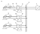
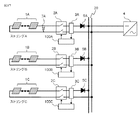
図1は、本発明の実施の形態1による直流発電システムの概略構成を示す回路図である。複数個の直流発電モジュール1Aが直列接続されてストリングAが形成されており、開閉器2Aを介して直流母線20に接続されている。同様に、複数個の直流発電モジュール1Bが直列接続されてストリングBが、複数個の直流発電モジュール1Cが直列接続されてストリングCが形成されており、それぞれ開閉器2B、2Cを介して直流母線20に接続されている。メガソーラにおいてはこのようなストリングが多数設けられることが多いが、図1ではストリングA、ストリングB、ストリングCの3つのストリングのみ図示している。開閉器2(2A、2B、2C・・)の近くに電圧電流センサ3(3A、3B、3C・・)が置かれており、電圧電流センサ3の出力を入力しアークを検出するアーク検出装置100(100A、100B、100C・・)が各回路に取り付けられている。直流母線はさらにパワーコンディショナ4側で合流する。直流発電モジュール1(1A、1B、1C・・)で発電された直流電力は、パワーコンディショナ4によって商用周波数の交流電力に変換されて、商用電力網を介して一般家庭や工場などの需要家に供給される。以降、直流発電モジュール1(1A、1B、1C・・)として太陽光発電モジュール(太陽光パネルとも称する)1(1A、1B、1C・・)を用いる太陽光発電システムを例に説明する。
FIG. 1 is a circuit diagram showing a schematic configuration of a DC power generation system according to
図2は、本発明の実施の形態1による直流発電システムのアーク検出装置100の構成を示すブロック図である。入力部110は電圧信号入力部111、電流信号入力部112からなる。入力部110は開閉器2の近くに設置されている電圧電流センサ3により検出される電圧および電流の信号データをアーク検出装置100に取り込む。取り込まれたデータはアーク解析部120に伝送される。アーク解析部120はアークノイズ解析部121と電圧電流変動解析部122からなる。アークノイズ解析部121は、アーク発生時の高周波ノイズを検知し、アーク発生を判定する。アークノイズ解析部121においてアーク発生と判定した後に、電圧電流変動解析部122においてアーク発生箇所やアークモードを特定する処理を行う。電圧電流変動解析部122では、アーク発生箇所が太陽光パネルと電圧電流センサ3の間か、もしくは電圧電流センサ3とパワーコンディショナ4の間かを判定する。さらに、アークのモードが直列アークか並列アークかを判定する。開閉器制御部130ではアークが発生した際に、健全な区間の運転を続けるために適切な開閉器2のみをトリップする指令を出す。最後に、出力部140の表示部141でアーク発生の有無、アーク発生箇所、アークモード、動作した開閉器を表示し、警報部142でアーク発生したと判断した際に警報を鳴らす。
FIG. 2 is a block diagram showing a configuration of
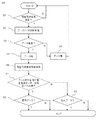
図3は、本発明の実施の形態1による直流発電システムのアーク検出装置100の動作を説明するフロー図である。アーク検出装置100において入力部110から入力される電圧電流信号が更新(ステップS1)されると、アークノイズ解析部121でアークノイズ解析(ステップS2)が実施される。アークノイズ解析の結果、直流発電システム内のアーク発生を判定する(ステップS3)。ステップ2およびステップ3をアーク検出ステップと称する。アーク発生有と判定(ステップ4)されると、電圧電流変動解析部122においてアーク発生前後の電圧電流が解析される(ステップS6)。アーク発生無と判定された場合(ステップS5)には最初に戻る。電圧電流変動解析部122では、所定期間の電圧および電流の信号データが保存されており、アーク発生有と判定された場合、アーク発生前後の電圧電流の変動パターンを解析しアーク発生箇所とアークモードを決定する。アーク発生箇所が電圧電流センサと太陽光パネルの間かどうかを判定(ステップS7)する。ステップ6およびステップ7を、アーク発生箇所特定ステップと称する。アーク発生箇所判定後、アークモードが直列アークかどうかを判定する(ステップS8、ステップS9)。また、アーク発生箇所特定ステップの後、開閉器を制御する開閉器制御ステップにおいて、開閉器を制御する。
FIG. 3 is a flowchart illustrating the operation of the
直流アークには直列アークと並列アークが存在する。まず、直列アークについて説明する。負荷を受けた電線に不測の破損や切断が発生すると、それにつながっている回路部分の先端間にアークが形成される。直列アークは、太陽光パネルと太陽光パネルの間、太陽光パネルと開閉器の間、開閉器とパワーコンディショナの間、破損した電線の先端間などに発生するアークである。ケーブルの劣化や施工ミス、ねじの緩みなどで発生する。 There are series arcs and parallel arcs in DC arcs. First, the series arc will be described. When an unexpected breakage or disconnection occurs in a loaded electric wire, an arc is formed between the tips of the circuit parts connected to it. A series arc is an arc generated between a solar panel and a solar panel, between a solar panel and a switch, between a switch and a power conditioner, between broken wire ends, and the like. This may occur due to cable deterioration, installation mistakes, or loose screws.
次に、並列アークについて説明する。並列アークは、極性が異なる2つの導体の間に不測の電流が流れた場合に発生する。これは動物が電線を噛んだ時や電線が劣化した時や、外部の力により電線が損傷した時などに発生し、絶縁体や保護機能の欠落をもたらし、極性が異なる金属部の接触を招くことで、アークが形成される。 Next, the parallel arc will be described. A parallel arc occurs when an unexpected current flows between two conductors of different polarities. This occurs when an animal bites an electric wire, when the electric wire deteriorates, or when the electric wire is damaged by an external force, resulting in a lack of insulation or protection function, and contact with metal parts with different polarities. Thus, an arc is formed.
図4は直列アーク6Aが太陽光パネル1Aと電圧電流センサ3Aの間で発生したときを示す概略図である。直列アーク6Aと同様の直列アークは、太陽光パネル1Bと電圧電流センサ3Bの間、または太陽光パネル1Cと電圧電流センサ3Cの間の回路上でも起こりえる。ただし、対称性を有しているため、ここでは直列アーク6Aが太陽光パネル1Aと電圧電流センサ3Aで発生したときを例にして説明する。
FIG. 4 is a schematic diagram showing when the series arc 6A is generated between the
直列アークや並列アークが発生すると一般に1kHz〜1MHz程度の範囲でアークノイズが発生する。アークノイズは1/fの特性を有しており、太陽光発電システム回路全体に微小のノイズを重畳させる。アークが発生していない時のノイズ強度と比較して、特に1kHzから100kHzの範囲において明確な違いがあるため、電流に重畳したアークノイズとして、少なくとも1kHzから100kHzの範囲の高周波ノイズを検知することで、アーク発生を判定できる。アークノイズの伝播は公知である。パワーコンディショナからのノイズをキャンセリングすることで容易に検知可能である。ただし、アーク発生をアークノイズのみで判定すると複数並列回路においては全てのアーク検出装置がアーク発生ありと判定してしまう。なぜなら、アークノイズが回路全体に伝播するためである。そこで、本特許ではアークノイズだけでなく、電圧電流変動特性を解析することでアーク発生箇所とアークモードを特定可能なアーク判定方法を提案する。 When a series arc or a parallel arc is generated, arc noise is generally generated in the range of about 1 kHz to 1 MHz. Arc noise has a 1 / f characteristic, and a small amount of noise is superimposed on the entire photovoltaic power generation system circuit. Compared with the noise intensity when no arc is generated, there is a clear difference especially in the range of 1 kHz to 100 kHz, so that high frequency noise in the range of at least 1 kHz to 100 kHz is detected as arc noise superimposed on the current. Thus, the occurrence of arc can be determined. The propagation of arc noise is well known. It can be easily detected by canceling noise from the inverter. However, if arc generation is determined only by arc noise, all arc detection devices determine that arc generation has occurred in a plurality of parallel circuits. This is because arc noise propagates throughout the circuit. Therefore, this patent proposes an arc determination method capable of specifying an arc occurrence location and an arc mode by analyzing not only arc noise but also voltage-current fluctuation characteristics.
図4の概略図で示す箇所で直列アークが発生した際の電圧電流変動特性を図5に示す。太陽光発電の電圧電流特性は日射強度により異なる。日射強度が大きいほど最大動作出力電流Ipmが増加し、日射強度が小さいほど最大動作出力電流Ipmは小さくなる。また、日射強度に依らず最大動作出力電圧Vpmは大きく変化しない。パワーコンディショナ4の制御によって常に最大電力となる動作点11を継続する。そのため、最大動作出力電圧Vpmおよび最大動作出力電流Ipmの出力が通常時の動作点である。また、各ストリングにおいて、ストリング自身が正常なとき、負荷が開放の場合の出力電圧Vocと負荷が短絡の場合の出力電流Iscが決まり、負荷の状態に応じて動作点は、電圧電流特性曲線10上となる。
FIG. 5 shows the voltage-current fluctuation characteristics when a series arc is generated at the location shown in the schematic diagram of FIG. The voltage-current characteristics of photovoltaic power generation vary depending on the solar radiation intensity. The maximum operating output current Ipm increases as the solar radiation intensity increases, and the maximum operating output current Ipm decreases as the solar radiation intensity decreases. Further, the maximum operation output voltage Vpm does not change greatly regardless of the solar radiation intensity. The
太陽光パネル1Aと電圧電流センサ3Aの間で直列アーク6Aが発生すると、電圧電流センサ3Aの電圧と電流は低下しアーク発生後の動作点12となる。動作点12は、正常動作の電圧電流特性曲線10から外れた動作点である。アークの発生により数μs〜数十μsで電圧電流が変動するため、アーク発生前の動作点11からアーク発生後の動作点12に移行する時間は1ms以下と速く、天候やパワーコンディショナによる動作点の変化と比べると極めて速い。電圧の低下量はアーク電圧に依存し、アーク電圧は最大動作電流に依存する。アーク発生により回路インピーダンスが増加し、電流も低下する。直列アークが発生していないストリングの電圧電流センサ3B、3Cの電圧は低下し、電流は増加し、動作点13となる。直列アークが発生していないストリングの電圧電流は太陽光発電の電圧電流特性曲線10上で動作することから、電圧低下に伴い電流は増加する。
When the series arc 6A is generated between the
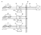
次に、図6の概略図で示す箇所で直列アークが発生した際の電圧電流変動特性を図7に示す。電圧電流センサ3Aとパワーコンディショナ4の間で直列アーク6Bが発生すると、電圧電流センサ3Aの電圧は増加し、電流は低下する。このとき、アーク発生後の動作点14となる。アーク発生により回路インピーダンスが増加し、電流が低下するためである。動作点14は、正常動作の電圧電流特性曲線10上の動作点となる。ストリングBおよびCの電圧電流センサ3Bおよび3Cも同様に、電圧は増加し、電流は低下する。このとき、ストリングBおよびCのアーク発生後の動作点14はストリングAのアーク発生後の動作点と一致する。回路の対称性から電圧と電流の変動量は同じとなる。
Next, FIG. 7 shows voltage-current fluctuation characteristics when a series arc is generated at the location shown in the schematic diagram of FIG. When the
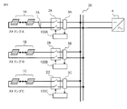
次に並列アークについて説明する。図8の概略図で示す箇所で並列アーク7Aが発生した際の電圧電流変動特性を図9に示す。太陽光パネル1Aと電圧電流センサ3Aの間で並列アーク7Aが発生すると、電圧電流センサ3Aの電圧と電流は低下しアーク発生後の動作点15となる。動作点15の電圧はアーク電圧程度(10V〜40V)となり、電流は他ストリングから逆流するため過大な電流が逆方向に流れる。動作点15は、正常動作の電圧電流特性曲線10から大幅に外れた動作点である。一方、他ストリングの電圧電流センサ3B、3Cの電圧は低下し、電流は増加し、アーク発生後の動作点16となる。動作点16の電圧はアーク電圧程度(10V〜40V)で、電流は短絡電流値と同等の値となる。図9に示すように、異常が生じていないストリングの動作点16は正常動作の電圧電流特性曲線10上の動作点である。
Next, the parallel arc will be described. FIG. 9 shows voltage-current fluctuation characteristics when the
次に、図10の概略図で示す箇所で並列アーク7Bが発生した際の電圧電流変動特性を図11に示す。電圧電流センサ3Aとパワーコンディショナ4の間で並列アーク7Bが発生すると、電圧電流センサ3Aの電圧は低下し、電流は増加しアーク発生後の動作点19となる。動作点19の電圧はアーク電圧程度(10V〜40V)となり、電圧電流特性曲線10から電流は短絡電流Iscに近い値となる。図11に示すように、ストリング内で異常が生じていないため、動作点16は正常動作の電圧電流特性曲線10上の動作点となる。他ストリングのアーク発生後の動作点はストリングAの動作点19と一致する。回路の対称性から電圧と電流の変動量は同じとなる。
Next, FIG. 11 shows voltage-current fluctuation characteristics when the
開閉器制御部130の動作、すなわち開閉器制御ステップの動作については、アーク発生箇所を判定した上で決定する。図4の直列アーク6Aが発生した際には、図5のアーク発生後の動作点12の電圧電流変動を示したセンサの信号が入力されたストリングAのアーク検出装置100Aが電圧電流センサ3Aの近傍の開閉器2Aをトリップする。これによって太陽光発電から流れる電流が止まり直列アークを消弧できる。開閉器2Aがトリップされると、ストリングBおよびストリングCの動作点は動作点13から動作点11に戻り、直流発電システムはストリングBとストリングCとで動作を継続できる。
The operation of the
図6の直列アーク6Bが発生した際には、図7のアーク発生後の電圧電流動作点として動作点14が一定時間継続したときに、アーク検出装置100A、100B、100C全てが、それぞれ開閉器2A、2B、2Cをトリップする。これによって太陽光発電から流れる電流が止まり直列アークを消弧できる。
When the
図8の並列アーク7Aが発生した際には、図9のアーク発生後の動作点15の電圧電流変動を示したセンサの信号が入力されたアーク検出装置100Aが電圧電流センサ3Aの近傍の開閉器2Aをトリップする。
When the
図10の並列アーク7Bが発生した際には、図11のアーク発生後の動作点19への電圧電流変動が一定時間継続したときにセンサの信号が入力されたアーク検出装置100A、100B、100C全てが、それぞれ開閉器2A、2B、2Cをトリップする。
When the
以上のように、アークノイズ解析部121においてアークが発生したと判断されたとき、それぞれのストリングのアーク検出装置100の電圧電流変動解析部122においてアーク発生前後の電圧電流動作点を解析し、アーク発生後の電圧電流動作点が正常動作の電圧電流特性曲線上から外れているときは、自己のストリングにおいてアークが発生したと判断して自己の開閉器2をトリップする。アーク発生後の電圧電流動作点が正常動作の電圧電流特性曲線上にあるときは、自己のストリングより外でアークが発生したと判断し、電圧電流動作点が所定時間動作点11とは異なる動作点を継続する場合は、自己の開閉器2をトリップする。図4や図8で示したようにストリングA内でアークが発生した場合は、まずストリングAの開閉器2Aがトリップされ、ストリングBやストリングCの動作点は動作点11に戻るため、開閉器2Bや開閉器2Cをトリップせずに済む。また、図6や図10で示したようにストリング外でアークが発生した場合は、正常動作の電圧電流特性曲線上の動作点14や動作点19が継続するため、所定時間これらの動作点が継続する場合は全ての開閉器2A、2B、2Cをトリップすることになり、直流発電システムが保護される。
As described above, when the arc
なお、本特許は図12のように電圧電流センサ3(3A、3B、3C・・)が開閉器と太陽光パネルの間に設置されている場合も同様の保護方法でアークを検出することができる。なぜならば、開閉器が閉じている間の電圧電流変動は同じであるからである。 In addition, this patent can detect an arc with the same protection method when the voltage / current sensor 3 (3A, 3B, 3C,...) Is installed between the switch and the solar panel as shown in FIG. it can. This is because the voltage-current fluctuation is the same while the switch is closed.
さらに、本特許は図13のようにアーク検出装置100(100A、100B、100C・・)と電圧電流センサ3(3A、3B、3C・・)が一体型であった場合にも同様のアーク解析でアーク保護を実現可能とする。電圧電流センサ3(3A、3B、3C・・)から出力される電圧と電流をアーク検出装置100(100A、100B、100C・・)に伝送可能であれば設置場所の限定はない。 Further, in this patent, as shown in FIG. 13, when the arc detection device 100 (100A, 100B, 100C...) And the voltage / current sensor 3 (3A, 3B, 3C. This makes it possible to achieve arc protection. As long as the voltage and current output from the voltage / current sensor 3 (3A, 3B, 3C,...) Can be transmitted to the arc detector 100 (100A, 100B, 100C,...), The installation location is not limited.
実施の形態2.
本特許は図14の逆流防止ダイオード5(5A、5B、5C・・)が備え付けられた太陽光発電システムへの適用も含む。逆流防止ダイオード5は、太陽光パネル1からパワーコンディショナ4へ流れるケーブル、すなわち正極側のケーブルに対して電流が流れる向きに設置される場合と、パワーコンディショナ4から太陽光パネル1側へ流れるケーブル、すなわち負極側のケーブルに対して電流が流れる向きに設置される場合がある。以下では、正極側のケーブルに逆流防止ダイオード5が設置されている場合を例にして説明する。
This patent also includes application to a photovoltaic power generation system equipped with the backflow prevention diode 5 (5A, 5B, 5C,...) Of FIG. The
図15の概略図で示すように、逆流防止ダイオード5(5A、5B、5C・・)がある場合で、電圧電流センサ3Aと太陽光パネル1A間で直列アークが発生した際の電圧電流変動特性は図5と同じである。太陽光パネル1Aと電圧電流センサ3Aの間で直列アーク6Aが発生すると、電圧電流センサ3Aの電圧と電流は低下しアーク発生後の動作点12となる。
As shown in the schematic diagram of FIG. 15, in the case where there is a backflow prevention diode 5 (5A, 5B, 5C,...), The voltage-current fluctuation characteristics when a series arc is generated between the voltage-
図16の概略図で示すように、逆流防止ダイオード5(5A、5B、5C・・)がある場合で、複数ストリングが接続された直流母線とパワーコンディショナ4の間で直列アークが発生した際の電圧電流変動特性は図7と同じである。この場合、それぞれのストリングの電圧電流センサ3A、3B、3Cの電圧は増加し、電流は低下する。このとき、それぞれのストリングにおいて、アーク発生後の動作点14となる。
As shown in the schematic diagram of FIG. 16, when there is a backflow prevention diode 5 (5A, 5B, 5C,...), When a series arc is generated between the DC bus connected to a plurality of strings and the power conditioner 4. The voltage-current fluctuation characteristics of are the same as in FIG. In this case, the voltages of the voltage /
図17の概略図で示す箇所で示すように、逆流防止ダイオード5(5A、5B、5C・・)がある場合で、ストリングAにおいて並列アーク7Aが発生した際の電圧電流変動特性を図18に示す。逆流防止ダイオードが接続された太陽光発電システム内の太陽光パネル1Aと電圧電流センサ3Aの間で並列アーク7Aが発生すると、電圧電流センサ3Aの電圧と電流は低下しアーク発生後の動作点17となる。動作点17の電圧はアーク電圧程度(10V〜40V)となり、電流は太陽光パネル1Aからの出力がなく、また逆流防止ダイオードにより他ストリングから逆流することがないため電流は0となる。一方、他ストリングの電圧電流センサ3B、3Cの電圧は低下し電流は増加し、別回路のアーク発生後の動作点18となる。動作点18の電圧はアーク電圧程度(10V〜40V)で、電流は短絡電流値と同等の値となる。
As shown in the schematic diagram of FIG. 17, the voltage-current fluctuation characteristics when the
図19の概略図で示すように、逆流防止ダイオードがある場合で、並列アーク7Bが発生した際の電圧電流変動特性は図11と同じである。電圧電流センサ3Aの電圧は低下し、電流は増加しアーク発生後の動作点19となる。動作点19の電圧はアーク電圧程度(10V〜40V)となり、太陽光発電の電圧電流特性曲線10から電流は短絡電流Iscに近い値となる。ストリングBやストリングCのアーク発生後の動作点はストリングAの動作点19と一致する。
As shown in the schematic diagram of FIG. 19, the voltage-current fluctuation characteristics when the
開閉器制御部130の動作については、図15、図16、図19の場合には図4、図6、図10の場合の開閉器動作指令と同じである。図17で示すように並列アークが発生した際には、アーク発生後の動作点18の電圧電流変動を示したセンサの信号が入力されたアーク検出装置が電圧電流センサ3Aの近傍の開閉器2Aをトリップする。
The operation of the
実施の形態3.
図20は本発明の実施の形態3による直流発電システムの構成を示す概略回路図である。実施の形態1および実施の形態2では、それぞれのストリングに備えられたアーク検出装置100が自己のストリングの開閉器2をトリップするかどうかを判断するようにした。本実施の形態3では、それぞれのストリングに備えられた電圧電流センサ3(3A、3B、・・・)から送られてきたデータを一つのアーク検出装置200で解析処理し、アーク発生箇所判定、アークモード判定、適切な開閉器動作指令を出力するよう構成されている。
FIG. 20 is a schematic circuit diagram showing a configuration of a DC power generation system according to
例えば、ストリングAの太陽光パネル1Aと電圧電流センサ3Aの間で並列アーク7Aが発生すると、ストリングAの電圧電流センサ3Aにおける動作点は図9に示す動作点15となり、ストリングBの電圧電流センサ3B、およびストリングCの電圧電流センサ3Cにおける動作点は図9に示す動作点16になる。また、直流母線20あるいは直流母線20よりもパワーコンディショナ4側で並列アーク7Bが発生すると、各ストリングの電圧電流センサ3における動作点は図11に示す動作点19になる。ここで、図9に示す動作点16と図11に示す動作点19はほとんど同じ動作点である。実施の形態1や実施の形態2の構成では、それぞれのストリングで単独にアーク発生を判断するため、ストリングBやストリングCでは、並列アークがストリングAで発生したか直流母線20あるいは直流母線20よりもパワーコンディショナ4側で発生したかを判断するのは難しい。このため、実施の形態1では、自己のストリング外でアークが発生したと判断した場合は、所定時間動作点が継続する場合に自己のストリングを切り離すよう開閉器をトリップさせることとした。
For example, when a
本実施の形態3では、図20に示すように、アーク検出装置200が全てのストリングの電圧電流センサ3(3A、3B、・・・)からの信号を入力して、総合的に判断することにより、アーク発生箇所を適切に判断できる。すなわち、図9で示すように、ストリングAにおける動作点が動作点15となり、他のストリングにおける動作点が動作点16となった場合は、ストリングAにおいて並列アーク7Aが発生したと判断でき、この場合は開閉器2Aのみをトリップさせる。一方、図11で示すように、全てのストリングの動作点が動作点19となった場合は、直流母線20あるいは直流母線20よりもパワーコンディショナ4側で並列アーク7Bが発生したと判断でき、直ちに、全てのストリングの開閉器2A、2B、2Cをトリップさせる。
In the third embodiment, as shown in FIG. 20, the
以上のように、それぞれのストリングに備えられた電圧電流センサ3((3A、3B、・・・)の信号を一つのアーク検出装置200において解析することにより、アーク発生箇所をより適切に判断でき、それぞれの開閉器に対してより適切な指令を送ることができる。特に、ストリング外でアークが発生した場合に、実施の形態1のように、異常な動作点が所定時間継続するのを待つことなく、直ちに全てのストリングを切り離せるというメリットがある。
As described above, by analyzing the signal of the voltage / current sensor 3 ((3A, 3B,...) Provided in each string in one
実施の形態4.
図21は、本発明の実施の形態4による直流発電システムの構成を示す概略回路図である。実施の形態4では、それぞれのストリングに備えられたアーク検出装置100(100A、100B、・・・)が、自己のストリングでアークが発生したかどうかを判断し、判断結果をアーク発生箇所特定装置201に送信する。アーク発生箇所特定装置201では、全てのアーク検出装置100(100A、100B、・・・)からの信号を入力して総合的に判断することにより、アーク発生箇所を特定する。Embodiment 4 FIG.
FIG. 21 is a schematic circuit diagram showing a configuration of a DC power generation system according to Embodiment 4 of the present invention. In the fourth embodiment, the arc detection device 100 (100A, 100B,...) Provided in each string determines whether or not an arc has occurred in its own string, and the determination result is used as the arc occurrence location specifying device. To 201. The arc occurrence
アーク発生箇所特定装置201は、全てのストリングのアーク検出装置100から、それぞれ自己のストリング外で並列アークが発生したとの判断結果が入力された場合は、直流母線20あるいは直流母線20よりもパワーコンディショナ4側で並列アーク7Bが発生したと判断し、全てのストリングの開閉器2(2A、2B、・・・)をトリップするように全てのアーク検出装置100に指令を送信する。全てのストリングのアーク検出装置100から、それぞれ自己のストリング外で直列アークが発生したとの判断結果が入力された場合は、直流母線20あるいは直流母線20よりもパワーコンディショナ4側で直列アークが発生したと判断し、全てのストリングの開閉器2(2A、2B、・・・)をトリップするように全てのアーク検出装置100に指令を送信する。
When the determination result that the parallel arc has occurred outside the own string is input from the
一方、アーク発生箇所特定装置201は、ある一つのストリングのアーク検出装置、例えばストリングAのアーク検出装置100Aから自己のストリングで並列アークが発生したとの判断結果が入力され、他のストリングのアーク検出装置からは自己のストリング外で並列アークが発生したとの判断結果が入力された場合は、ストリングA以外の開閉器はトリップさせないとの指令を、ストリングA以外のアーク検出装置または開閉器に送信する。直列アークの場合も同様である。
On the other hand, the arc occurrence
以上において、自己のストリングでアークが発生したと判断したアーク検出装置は、自己の開閉器を直ちにトリップする。一方、自己のストリング外でアークが発生したと判断したアーク検出装置は、アーク発生箇所特定装置201からの信号を待って自己の開閉器をトリップする。
In the above, the arc detection device that has determined that an arc has occurred in its own string immediately trips its own switch. On the other hand, the arc detection device that has determined that an arc has occurred outside its own string waits for a signal from the arc occurrence
本実施の形態4による直流発電システムによれば、ストリング外でアークが発生した場合に、実施の形態1のように、異常な動作点が所定時間継続するのを待つのではなく、アーク発生箇所特定装置201かアーク発生箇所を特定するため、より適切なアーク発生箇所の特定を行える。
According to the DC power generation system according to the fourth embodiment, when an arc is generated outside the string, the arc generation point is not waited for an abnormal operating point to continue for a predetermined time as in the first embodiment. Since the identifying
なお、本発明は、その発明の範囲内において、各実施の形態を組み合わせたり、各実施の形態を適宜、変形、省略したりすることが可能である。 It should be noted that the present invention can be combined with each other within the scope of the invention, or can be appropriately modified or omitted from each embodiment.
1、1A、1B、1C 太陽光パネル、2、2A、2B、2C 開閉器、
3、3A、3B、3C 電圧電流センサ、4 パワーコンディショナ、
5A、5B、5C ダイオード、6A、6B 直列アーク、
7A、7B 並列アーク、100 アーク検出装置、110 入力部、
120 アーク解析部、121 アークノイズ解析部、
122 電圧電流変動解析部、130 開閉器制御部。1, 1A, 1B, 1C solar panel, 2, 2A, 2B, 2C switch,
3, 3A, 3B, 3C Voltage current sensor, 4 Power conditioner,
5A, 5B, 5C diode, 6A, 6B series arc,
7A, 7B parallel arc, 100 arc detector, 110 input unit,
120 arc analysis unit, 121 arc noise analysis unit,
122 Voltage-current fluctuation analysis unit, 130 Switch control unit.
Claims (13)
それぞれのストリングは、出力側に、当該ストリングの出力電圧と出力電流を検出する電圧電流センサと、当該ストリングの前記直流母線への接続を遮断する開閉器とを備え、
前記電圧電流センサの信号のノイズに基づいて前記直流発電システムに発生するアークを検出するアークノイズ解析部と、前記アークノイズ解析部においてアークが検出された場合に、前記電圧電流センサからの信号により各ストリングの出力の電圧電流動作点を解析し、電圧電流動作点の、前記アークが検出された前後の変動に基づいて、前記アークの発生箇所を特定する電圧電流変動解析部と、前記電圧電流変動解析部におけるアーク特定結果に基づいて前記開閉器の開閉を制御する開閉器制御部を有するアーク検出装置を備えたことを特徴とする直流発電システム。 In a DC power generation system in which a plurality of strings in which a plurality of DC power generation modules are connected in series are connected in parallel to the DC bus and supplies power to the DC bus,
Each string includes, on the output side, a voltage / current sensor that detects an output voltage and an output current of the string, and a switch that interrupts connection of the string to the DC bus,
An arc noise analysis unit that detects an arc generated in the DC power generation system based on noise of a signal of the voltage / current sensor, and when an arc is detected in the arc noise analysis unit, a signal from the voltage / current sensor A voltage-current fluctuation analyzing unit that analyzes a voltage-current operating point of an output of each string and identifies a generation point of the arc based on a fluctuation of the voltage-current operating point before and after the arc is detected; A DC power generation system comprising an arc detection device having a switch control unit that controls opening and closing of the switch based on an arc identification result in a fluctuation analysis unit.
前記ストリングに発生するノイズに基づいて前記直流発電システムに発生するアークを検出するアーク検出ステップと、
前記アークが検出された場合に、前記複数のストリングの各ストリングの出力の電圧電流動作点を解析し、電圧電流動作点の、前記アークが検出された前後の変動に基づいて、前記アークの発生箇所を特定するアーク発生箇所特定ステップと、
このアークの発生箇所の特定結果に基づいて前記開閉器の開閉を制御する開閉器制御ステップと
を含むことを特徴とする直流発電システムの保護方法。 A plurality of strings in which a plurality of DC power generation modules are connected in series are respectively connected in parallel to a DC bus via a switch, and the DC power generation system supplies power to the DC bus.
An arc detection step of detecting an arc generated in the DC power generation system based on noise generated in the string;
When the arc is detected, the voltage current operating point of the output of each string of the plurality of strings is analyzed, and the occurrence of the arc is generated based on the fluctuation of the voltage current operating point before and after the arc is detected. An arc occurrence location identifying step for identifying a location;
And a switch control step for controlling the opening and closing of the switch based on the result of specifying the location where the arc is generated.
前記開閉器制御ステップにおいて、アークが発生したと特定したストリングの前記開閉器をトリップすることを特徴とする請求項9に記載の直流発電システムの保護方法。 In the arc occurrence location specifying step, when the voltage / current operating point after the arc is detected is an operating point deviating from the voltage / current characteristic curve during normal operation, it is specified that an arc has occurred in the string,
The method for protecting a DC power generation system according to claim 9, wherein, in the switch control step, the switch of the string identified as having an arc is tripped.
前記開閉器制御ステップにおいて、前記全てのストリングの前記開閉器をトリップすることを特徴とする請求項9に記載の直流発電システムの保護方法。 In the arc generation location specifying step, for all strings, when the voltage-current operating point after the arc is detected is on the voltage-current characteristic curve during normal operation, an arc has occurred outside all the strings. And identify
The method for protecting a DC power generation system according to claim 9, wherein in the switch control step, the switches of all the strings are tripped.
Applications Claiming Priority (3)
| Application Number | Priority Date | Filing Date | Title |
|---|---|---|---|
| JP2013174105 | 2013-08-26 | ||
| JP2013174105 | 2013-08-26 | ||
| PCT/JP2014/050748 WO2015029458A1 (en) | 2013-08-26 | 2014-01-17 | Dc power generation system and protection method for dc power generation system |
Publications (2)
| Publication Number | Publication Date |
|---|---|
| JPWO2015029458A1 JPWO2015029458A1 (en) | 2017-03-02 |
| JP6132919B2 true JP6132919B2 (en) | 2017-05-24 |
Family
ID=52586045
Family Applications (1)
| Application Number | Title | Priority Date | Filing Date |
|---|---|---|---|
| JP2015534010A Active JP6132919B2 (en) | 2013-08-26 | 2014-01-17 | DC power generation system and method for protecting DC power generation system |
Country Status (5)
| Country | Link |
|---|---|
| US (1) | US9866017B2 (en) |
| EP (1) | EP3041104B1 (en) |
| JP (1) | JP6132919B2 (en) |
| CN (1) | CN105474494B (en) |
| WO (1) | WO2015029458A1 (en) |
Families Citing this family (27)
| Publication number | Priority date | Publication date | Assignee | Title |
|---|---|---|---|---|
| FR2977677B1 (en) | 2011-07-04 | 2013-08-23 | Commissariat Energie Atomique | DETECTION OF ELECTRIC ARCS IN PHOTOVOLTAIC FACILITIES |
| US20150194801A1 (en) * | 2012-07-09 | 2015-07-09 | Solarbos, Inc. | Reverse current fault prevention in power combination of solar panel array systems |
| FR3010261B1 (en) * | 2013-08-29 | 2015-10-02 | Commissariat Energie Atomique | DETECTION OF AN ELECTRICAL ARC IN PARALLEL ON THE MAIN TERMINALS OF A PHOTOVOLTAIC INSTALLATION |
| FR3010260B1 (en) | 2013-08-29 | 2015-10-02 | Commissariat Energie Atomique | DETECTION OF ELECTRIC ARCS IN PHOTOVOLTAIC FACILITIES |
| JP6246062B2 (en) * | 2014-04-30 | 2017-12-13 | 三菱電機株式会社 | DC power generation system and method for protecting DC power generation system |
| FR3044489B1 (en) * | 2015-12-01 | 2017-12-22 | Commissariat Energie Atomique | METHOD AND DEVICE FOR DETECTING A PARASITE ELECTRIC ARC IN A PHOTOVOLTAIC INSTALLATION |
| JP6597394B2 (en) * | 2016-02-29 | 2019-10-30 | オムロン株式会社 | Arc generating position detecting device and arc generating position detecting method |
| CN109417285B (en) * | 2016-06-21 | 2020-11-06 | 三菱电机株式会社 | Direct current electric loop protection device and arc detection method |
| US11277000B2 (en) | 2016-06-21 | 2022-03-15 | Mitsubishi Electric Corporation | DC electrical circuit protection apparatus and ARC detection method |
| JP2018028498A (en) * | 2016-08-19 | 2018-02-22 | 富士電機機器制御株式会社 | Arc fault detection system |
| CN115473211A (en) * | 2016-09-12 | 2022-12-13 | 菲尼克斯电气公司 | Direct-current generator, direct-current hybrid switching mechanism, application and method |
| LU93202B1 (en) * | 2016-09-12 | 2018-04-05 | Phoenix Contact Gmbh & Co Kg Intellectual Property Licenses & Standards | Multi-strand photovoltaic system, method for operating such and reverse current protection circuit for such |
| JP6834334B2 (en) * | 2016-10-17 | 2021-02-24 | 富士電機機器制御株式会社 | Arc failure detection system |
| JP6834458B2 (en) * | 2016-12-20 | 2021-02-24 | 富士電機機器制御株式会社 | Arc failure detection system |
| WO2018150876A1 (en) * | 2017-02-14 | 2018-08-23 | パナソニックIpマネジメント株式会社 | Arc detection circuit, switch system, power conditioner system and arc detection method |
| JP6807552B2 (en) * | 2017-02-14 | 2021-01-06 | パナソニックIpマネジメント株式会社 | Arc detection circuit, switch system, power conditioner system and arc detection method |
| JP2020012727A (en) * | 2018-07-18 | 2020-01-23 | 日本電信電話株式会社 | Line check device and line check method |
| CN110095702A (en) * | 2019-05-22 | 2019-08-06 | 安徽升隆电气有限公司 | A kind of arc performance analysis instrument |
| JP7370666B2 (en) * | 2019-11-01 | 2023-10-30 | 日東工業株式会社 | discharge detection system |
| CN110618366A (en) * | 2019-11-05 | 2019-12-27 | 阳光电源股份有限公司 | Direct current arc detection method and device |
| KR102341332B1 (en) * | 2019-12-03 | 2021-12-21 | 한국에너지기술연구원 | Device for detecting arc in output path of energy source |
| CN111817586B (en) * | 2020-07-07 | 2021-05-04 | 武汉理工大学 | Rectifying power supply device for mine direct-current overhead line and overhead line short circuit detection method thereof |
| CN111983402A (en) * | 2020-08-20 | 2020-11-24 | 阳光电源股份有限公司 | Direct-current arc fault detection method and photovoltaic inversion system |
| MX2023003361A (en) * | 2020-09-25 | 2023-03-29 | Enphase Energy Inc | High-power microinverter and system. |
| CN112468086B (en) * | 2020-11-13 | 2022-01-25 | 丰郅(上海)新能源科技有限公司 | Arc monitoring system and method applied to photovoltaic energy |
| CN112462176B (en) * | 2020-11-13 | 2022-06-28 | 丰郅(上海)新能源科技有限公司 | Device and method for supporting detection of photovoltaic system direct current arc fault |
| CN113938039A (en) * | 2021-09-09 | 2022-01-14 | 华为数字能源技术有限公司 | Photovoltaic system, inverter and direct current arc detection method |
Family Cites Families (19)
| Publication number | Priority date | Publication date | Assignee | Title |
|---|---|---|---|---|
| MXPA03004171A (en) | 2000-11-13 | 2003-09-22 | Eaton Corp | Detection of arcing in dc electrical systems. |
| US20040027749A1 (en) | 2001-11-09 | 2004-02-12 | Zuercher Joseph C. | Detection of arcing in dc electrical systems |
| US6984987B2 (en) * | 2003-06-12 | 2006-01-10 | Sharper Image Corporation | Electro-kinetic air transporter and conditioner devices with enhanced arching detection and suppression features |
| CN1696723A (en) * | 2004-05-14 | 2005-11-16 | 人间电气技术株式会社 | Electric arc fault detector |
| US20070279068A1 (en) * | 2006-05-31 | 2007-12-06 | Harres Daniel N | Power diagnostic system and method |
| US7368918B2 (en) * | 2006-07-27 | 2008-05-06 | Siemens Energy & Automation | Devices, systems, and methods for adaptive RF sensing in arc fault detection |
| CN101308108B (en) * | 2007-05-15 | 2011-06-29 | 清华大学 | Preparation method of sensor embodying one-dimensional nano material sensitive element |
| US8179145B2 (en) * | 2008-01-24 | 2012-05-15 | Siemens Industry, Inc. | Method and apparatus for testing AFCI device for series arc detection |
| JP5419579B2 (en) * | 2009-05-28 | 2014-02-19 | 京セラ株式会社 | Arc detection means and control means and communication means using the same |
| AU2010275466B2 (en) * | 2009-07-23 | 2015-11-26 | Enphase Energy, Inc. | Method and apparatus for detection and control of DC arc faults |
| AT509251A1 (en) * | 2009-08-14 | 2011-07-15 | Fronius Int Gmbh | 4 EXPERTS IN THE FIELD OF ARC FLASH IN PHOTOVOLTAIC PLANTS AND ONE SUCH PHOTOVOLTAIC PLANT |
| US20110090607A1 (en) | 2009-10-20 | 2011-04-21 | Luebke Charles J | String and system employing direct current electrical generating modules and a number of string protectors |
| US8218274B2 (en) * | 2009-12-15 | 2012-07-10 | Eaton Corporation | Direct current arc fault circuit interrupter, direct current arc fault detector, noise blanking circuit for a direct current arc fault circuit interrupter, and method of detecting arc faults |
| KR20120032925A (en) * | 2010-09-29 | 2012-04-06 | 삼성전자주식회사 | Electric apparatus, electric apparatus system and method for detecting arc fault thereof |
| GB2485527B (en) | 2010-11-09 | 2012-12-19 | Solaredge Technologies Ltd | Arc detection and prevention in a power generation system |
| CN102288857B (en) * | 2011-05-18 | 2013-06-19 | 浙江科技学院 | Fault arc identification and detection method and detection protection device |
| JP5888972B2 (en) * | 2011-12-22 | 2016-03-22 | 三菱電機株式会社 | Solar power system |
| DE102012104314B4 (en) * | 2012-05-18 | 2014-04-10 | Sma Solar Technology Ag | Method and device for locating and extinguishing an arc |
| US9768605B2 (en) * | 2014-12-29 | 2017-09-19 | Eaton Corporation | Arc fault detection system and method and circuit interrupter employing same |
-
2014
- 2014-01-17 WO PCT/JP2014/050748 patent/WO2015029458A1/en active Application Filing
- 2014-01-17 JP JP2015534010A patent/JP6132919B2/en active Active
- 2014-01-17 CN CN201480046617.5A patent/CN105474494B/en active Active
- 2014-01-17 US US14/911,238 patent/US9866017B2/en active Active
- 2014-01-17 EP EP14840613.5A patent/EP3041104B1/en active Active
Also Published As
| Publication number | Publication date |
|---|---|
| US20160181799A1 (en) | 2016-06-23 |
| JPWO2015029458A1 (en) | 2017-03-02 |
| EP3041104A4 (en) | 2017-06-07 |
| CN105474494B (en) | 2017-10-03 |
| WO2015029458A1 (en) | 2015-03-05 |
| EP3041104A1 (en) | 2016-07-06 |
| EP3041104B1 (en) | 2021-06-02 |
| US9866017B2 (en) | 2018-01-09 |
| CN105474494A (en) | 2016-04-06 |
Similar Documents
| Publication | Publication Date | Title |
|---|---|---|
| JP6132919B2 (en) | DC power generation system and method for protecting DC power generation system | |
| JP6246062B2 (en) | DC power generation system and method for protecting DC power generation system | |
| US9853443B2 (en) | ARC fault detection and extinguishing | |
| US9070797B2 (en) | Photovoltaic installation | |
| KR101491013B1 (en) | Solar generating system with solar cell connecting apparatus having leakage current and fire signatures monitoring function | |
| EP2729821B1 (en) | Method and system for detecting an arc fault in a photovoltaic power system | |
| US9995796B1 (en) | Identifying an arc-fault type in photovoltaic arrays | |
| CN110463040B (en) | Method for controlling a DC switch, DC switch and DC voltage system | |
| CN109417285B (en) | Direct current electric loop protection device and arc detection method | |
| JP5888972B2 (en) | Solar power system | |
| US9257829B2 (en) | Grounding apparatus | |
| WO2011157305A1 (en) | Fault protection of hvdc transmission lines | |
| US9831825B2 (en) | Solar photovoltaic system protecting apparatus and solar photovoltaic system protecting method | |
| US20170317500A1 (en) | System and method of sensing and isolating a ground fault in a dc-to-ac power conversion system | |
| JPWO2017221493A1 (en) | DC electric circuit protection device and arc detection method | |
| JP2018028498A (en) | Arc fault detection system | |
| CN115663769B (en) | Direct-current parallel arc protection and positioning system and method for photovoltaic power generation system | |
| JPWO2018150876A1 (en) | Arc detection circuit, switch system, power conditioner system, and arc detection method | |
| JP2016157364A (en) | Power control unit and control method thereof | |
| KR101881411B1 (en) | Arc detection and shutdown method in pv system and pv energy storage system | |
| JP6597394B2 (en) | Arc generating position detecting device and arc generating position detecting method | |
| KR20120086558A (en) | Solar power generation system with monitoring and neutral line replacement | |
| JP6958146B2 (en) | Arc detector | |
| EP3391489B1 (en) | Ground fault detection and interrupt system | |
| JP2018100877A (en) | Arc fault detection system |
Legal Events
| Date | Code | Title | Description |
|---|---|---|---|
| A131 | Notification of reasons for refusal |
Free format text: JAPANESE INTERMEDIATE CODE: A131 Effective date: 20170214 |
|
| A521 | Request for written amendment filed |
Free format text: JAPANESE INTERMEDIATE CODE: A523 Effective date: 20170310 |
|
| TRDD | Decision of grant or rejection written | ||
| A01 | Written decision to grant a patent or to grant a registration (utility model) |
Free format text: JAPANESE INTERMEDIATE CODE: A01 Effective date: 20170321 |
|
| A61 | First payment of annual fees (during grant procedure) |
Free format text: JAPANESE INTERMEDIATE CODE: A61 Effective date: 20170418 |
|
| R151 | Written notification of patent or utility model registration |
Ref document number: 6132919 Country of ref document: JP Free format text: JAPANESE INTERMEDIATE CODE: R151 |
|
| R250 | Receipt of annual fees |
Free format text: JAPANESE INTERMEDIATE CODE: R250 |
|
| R250 | Receipt of annual fees |
Free format text: JAPANESE INTERMEDIATE CODE: R250 |
|
| R250 | Receipt of annual fees |
Free format text: JAPANESE INTERMEDIATE CODE: R250 |
|
| R250 | Receipt of annual fees |
Free format text: JAPANESE INTERMEDIATE CODE: R250 |
|
| R250 | Receipt of annual fees |
Free format text: JAPANESE INTERMEDIATE CODE: R250 |