JP6130757B2 - Photoelectric conversion material, method for producing the same, and organic thin film solar cell using the same - Google Patents
Photoelectric conversion material, method for producing the same, and organic thin film solar cell using the same Download PDFInfo
- Publication number
- JP6130757B2 JP6130757B2 JP2013183519A JP2013183519A JP6130757B2 JP 6130757 B2 JP6130757 B2 JP 6130757B2 JP 2013183519 A JP2013183519 A JP 2013183519A JP 2013183519 A JP2013183519 A JP 2013183519A JP 6130757 B2 JP6130757 B2 JP 6130757B2
- Authority
- JP
- Japan
- Prior art keywords
- photoelectric conversion
- polymer
- conversion material
- polyphenylene
- general formula
- Prior art date
- Legal status (The legal status is an assumption and is not a legal conclusion. Google has not performed a legal analysis and makes no representation as to the accuracy of the status listed.)
- Active
Links
- 238000006243 chemical reaction Methods 0.000 title claims description 177
- 239000000463 material Substances 0.000 title claims description 56
- 239000010409 thin film Substances 0.000 title claims description 36
- 238000004519 manufacturing process Methods 0.000 title claims description 17
- 229920000642 polymer Polymers 0.000 claims description 212
- OKTJSMMVPCPJKN-UHFFFAOYSA-N Carbon Chemical compound [C] OKTJSMMVPCPJKN-UHFFFAOYSA-N 0.000 claims description 182
- 229910021389 graphene Inorganic materials 0.000 claims description 135
- -1 polyphenylene Polymers 0.000 claims description 116
- 229920000265 Polyparaphenylene Polymers 0.000 claims description 114
- 125000003545 alkoxy group Chemical group 0.000 claims description 69
- 239000000178 monomer Substances 0.000 claims description 60
- 150000001875 compounds Chemical class 0.000 claims description 50
- 229910052799 carbon Inorganic materials 0.000 claims description 44
- 238000006116 polymerization reaction Methods 0.000 claims description 19
- 238000000034 method Methods 0.000 claims description 15
- 125000004432 carbon atom Chemical group C* 0.000 claims description 4
- 239000003610 charcoal Substances 0.000 claims 1
- 239000000370 acceptor Substances 0.000 description 63
- 238000004768 lowest unoccupied molecular orbital Methods 0.000 description 43
- 229910052739 hydrogen Inorganic materials 0.000 description 34
- 239000001257 hydrogen Substances 0.000 description 34
- 239000003960 organic solvent Substances 0.000 description 32
- MCEWYIDBDVPMES-UHFFFAOYSA-N [60]pcbm Chemical compound C123C(C4=C5C6=C7C8=C9C%10=C%11C%12=C%13C%14=C%15C%16=C%17C%18=C(C=%19C=%20C%18=C%18C%16=C%13C%13=C%11C9=C9C7=C(C=%20C9=C%13%18)C(C7=%19)=C96)C6=C%11C%17=C%15C%13=C%15C%14=C%12C%12=C%10C%10=C85)=C9C7=C6C2=C%11C%13=C2C%15=C%12C%10=C4C23C1(CCCC(=O)OC)C1=CC=CC=C1 MCEWYIDBDVPMES-UHFFFAOYSA-N 0.000 description 29
- 238000004770 highest occupied molecular orbital Methods 0.000 description 29
- UFHFLCQGNIYNRP-UHFFFAOYSA-N Hydrogen Chemical compound [H][H] UFHFLCQGNIYNRP-UHFFFAOYSA-N 0.000 description 28
- 125000000217 alkyl group Chemical group 0.000 description 21
- 229920000301 poly(3-hexylthiophene-2,5-diyl) polymer Polymers 0.000 description 20
- 230000000379 polymerizing effect Effects 0.000 description 15
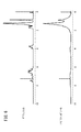
- 238000010521 absorption reaction Methods 0.000 description 14
- 239000000203 mixture Substances 0.000 description 13
- 230000005525 hole transport Effects 0.000 description 11
- 238000001228 spectrum Methods 0.000 description 11
- 238000010248 power generation Methods 0.000 description 9
- 239000000126 substance Substances 0.000 description 9
- 0 *C(C1)C(C#C*)=CC(*)=C1C#C* Chemical compound *C(C1)C(C#C*)=CC(*)=C1C#C* 0.000 description 8
- 238000005481 NMR spectroscopy Methods 0.000 description 8
- 230000001747 exhibiting effect Effects 0.000 description 8
- 238000000870 ultraviolet spectroscopy Methods 0.000 description 8
- 125000003118 aryl group Chemical group 0.000 description 7
- 230000008033 biological extinction Effects 0.000 description 7
- 239000010408 film Substances 0.000 description 7
- 238000009434 installation Methods 0.000 description 7
- FUEGWHHUYNHBNI-UHFFFAOYSA-N 1-[4-(2-oxo-2-phenylacetyl)phenyl]-2-phenylethane-1,2-dione Chemical group C=1C=CC=CC=1C(=O)C(=O)C(C=C1)=CC=C1C(=O)C(=O)C1=CC=CC=C1 FUEGWHHUYNHBNI-UHFFFAOYSA-N 0.000 description 6
- OKKJLVBELUTLKV-UHFFFAOYSA-N Methanol Chemical compound OC OKKJLVBELUTLKV-UHFFFAOYSA-N 0.000 description 6
- 150000002431 hydrogen Chemical class 0.000 description 6
- 239000011259 mixed solution Substances 0.000 description 6
- NAWXUBYGYWOOIX-SFHVURJKSA-N (2s)-2-[[4-[2-(2,4-diaminoquinazolin-6-yl)ethyl]benzoyl]amino]-4-methylidenepentanedioic acid Chemical compound C1=CC2=NC(N)=NC(N)=C2C=C1CCC1=CC=C(C(=O)N[C@@H](CC(=C)C(O)=O)C(O)=O)C=C1 NAWXUBYGYWOOIX-SFHVURJKSA-N 0.000 description 5
- OMKYPMWDCZHYHC-UHFFFAOYSA-N CCCCCCCCCCOc1cccc(OCCCCCCCCCC)c1CC(C)=O Chemical compound CCCCCCCCCCOc1cccc(OCCCCCCCCCC)c1CC(C)=O OMKYPMWDCZHYHC-UHFFFAOYSA-N 0.000 description 5
- 239000003054 catalyst Substances 0.000 description 5
- 239000000470 constituent Substances 0.000 description 5
- QRRKXCPLJGPVHN-UHFFFAOYSA-N hexabenzocoronene Chemical group C12C(C(=C34)C(=C56)C7=C89)=C%10C7=C7C%11=CC=CC7=C8C=CC=C9C5=CC=CC6=C3C=CC=C4C1=CC=CC2=C1C%10=C%11C=CC1 QRRKXCPLJGPVHN-UHFFFAOYSA-N 0.000 description 5
- 125000002496 methyl group Chemical group [H]C([H])([H])* 0.000 description 5
- 125000001997 phenyl group Chemical group [H]C1=C([H])C([H])=C(*)C([H])=C1[H] 0.000 description 5
- 239000004065 semiconductor Substances 0.000 description 5
- 125000003808 silyl group Chemical group [H][Si]([H])([H])[*] 0.000 description 5
- 239000000243 solution Substances 0.000 description 5
- 239000000758 substrate Substances 0.000 description 5
- YFKBXYGUSOXJGS-UHFFFAOYSA-N 1,3-Diphenyl-2-propanone Chemical compound C=1C=CC=CC=1CC(=O)CC1=CC=CC=C1 YFKBXYGUSOXJGS-UHFFFAOYSA-N 0.000 description 4
- LRHPLDYGYMQRHN-UHFFFAOYSA-N N-Butanol Chemical compound CCCCO LRHPLDYGYMQRHN-UHFFFAOYSA-N 0.000 description 4
- WYURNTSHIVDZCO-UHFFFAOYSA-N Tetrahydrofuran Chemical compound C1CCOC1 WYURNTSHIVDZCO-UHFFFAOYSA-N 0.000 description 4
- 238000000862 absorption spectrum Methods 0.000 description 4
- VSCWAEJMTAWNJL-UHFFFAOYSA-K aluminium trichloride Chemical compound Cl[Al](Cl)Cl VSCWAEJMTAWNJL-UHFFFAOYSA-K 0.000 description 4
- NDKBVBUGCNGSJJ-UHFFFAOYSA-M benzyltrimethylammonium hydroxide Chemical compound [OH-].C[N+](C)(C)CC1=CC=CC=C1 NDKBVBUGCNGSJJ-UHFFFAOYSA-M 0.000 description 4
- 230000015572 biosynthetic process Effects 0.000 description 4
- RBTARNINKXHZNM-UHFFFAOYSA-K iron trichloride Chemical compound Cl[Fe](Cl)Cl RBTARNINKXHZNM-UHFFFAOYSA-K 0.000 description 4
- 239000011968 lewis acid catalyst Substances 0.000 description 4
- ZCSHNCUQKCANBX-UHFFFAOYSA-N lithium diisopropylamide Chemical compound [Li+].CC(C)[N-]C(C)C ZCSHNCUQKCANBX-UHFFFAOYSA-N 0.000 description 4
- PQXKHYXIUOZZFA-UHFFFAOYSA-M lithium fluoride Chemical compound [Li+].[F-] PQXKHYXIUOZZFA-UHFFFAOYSA-M 0.000 description 4
- 230000008569 process Effects 0.000 description 4
- 238000005096 rolling process Methods 0.000 description 4
- 239000002904 solvent Substances 0.000 description 4
- MYMSJFSOOQERIO-UHFFFAOYSA-N 1-bromodecane Chemical compound CCCCCCCCCCBr MYMSJFSOOQERIO-UHFFFAOYSA-N 0.000 description 3
- HOQCIRZNQIXFIJ-UHFFFAOYSA-N CCCCCCCCCCOc1ccccc1C#Cc1ccc(cc1)-c1ccc(cc1)C#Cc1ccccc1OCCCCCCCCCC Chemical group CCCCCCCCCCOc1ccccc1C#Cc1ccc(cc1)-c1ccc(cc1)C#Cc1ccccc1OCCCCCCCCCC HOQCIRZNQIXFIJ-UHFFFAOYSA-N 0.000 description 3
- KDLHZDBZIXYQEI-UHFFFAOYSA-N Palladium Chemical compound [Pd] KDLHZDBZIXYQEI-UHFFFAOYSA-N 0.000 description 3
- YXFVVABEGXRONW-UHFFFAOYSA-N Toluene Chemical compound CC1=CC=CC=C1 YXFVVABEGXRONW-UHFFFAOYSA-N 0.000 description 3
- 125000002252 acyl group Chemical group 0.000 description 3
- 238000013459 approach Methods 0.000 description 3
- 238000012672 diels-alder polymerization Methods 0.000 description 3
- 125000000524 functional group Chemical group 0.000 description 3
- SYSQUGFVNFXIIT-UHFFFAOYSA-N n-[4-(1,3-benzoxazol-2-yl)phenyl]-4-nitrobenzenesulfonamide Chemical class C1=CC([N+](=O)[O-])=CC=C1S(=O)(=O)NC1=CC=C(C=2OC3=CC=CC=C3N=2)C=C1 SYSQUGFVNFXIIT-UHFFFAOYSA-N 0.000 description 3
- YTVNOVQHSGMMOV-UHFFFAOYSA-N naphthalenetetracarboxylic dianhydride Chemical compound C1=CC(C(=O)OC2=O)=C3C2=CC=C2C(=O)OC(=O)C1=C32 YTVNOVQHSGMMOV-UHFFFAOYSA-N 0.000 description 3
- 150000002894 organic compounds Chemical class 0.000 description 3
- RFFLAFLAYFXFSW-UHFFFAOYSA-N 1,2-dichlorobenzene Chemical compound ClC1=CC=CC=C1Cl RFFLAFLAYFXFSW-UHFFFAOYSA-N 0.000 description 2
- SKIDNYUZJPMKFC-UHFFFAOYSA-N 1-iododecane Chemical compound CCCCCCCCCCI SKIDNYUZJPMKFC-UHFFFAOYSA-N 0.000 description 2
- IXHWGNYCZPISET-UHFFFAOYSA-N 2-[4-(dicyanomethylidene)-2,3,5,6-tetrafluorocyclohexa-2,5-dien-1-ylidene]propanedinitrile Chemical compound FC1=C(F)C(=C(C#N)C#N)C(F)=C(F)C1=C(C#N)C#N IXHWGNYCZPISET-UHFFFAOYSA-N 0.000 description 2
- KQDJTBPASNJQFQ-UHFFFAOYSA-N 2-iodophenol Chemical compound OC1=CC=CC=C1I KQDJTBPASNJQFQ-UHFFFAOYSA-N 0.000 description 2
- NLZUEZXRPGMBCV-UHFFFAOYSA-N Butylhydroxytoluene Chemical compound CC1=CC(C(C)(C)C)=C(O)C(C(C)(C)C)=C1 NLZUEZXRPGMBCV-UHFFFAOYSA-N 0.000 description 2
- XMWRBQBLMFGWIX-UHFFFAOYSA-N C60 fullerene Chemical compound C12=C3C(C4=C56)=C7C8=C5C5=C9C%10=C6C6=C4C1=C1C4=C6C6=C%10C%10=C9C9=C%11C5=C8C5=C8C7=C3C3=C7C2=C1C1=C2C4=C6C4=C%10C6=C9C9=C%11C5=C5C8=C3C3=C7C1=C1C2=C4C6=C2C9=C5C3=C12 XMWRBQBLMFGWIX-UHFFFAOYSA-N 0.000 description 2
- OILVQGQDOWAFOR-UHFFFAOYSA-N CCCCCCCCCCOc1ccccc1C#Cc1ccc(cc1)C#Cc1ccccc1OCCCCCCCCCC Chemical compound CCCCCCCCCCOc1ccccc1C#Cc1ccc(cc1)C#Cc1ccccc1OCCCCCCCCCC OILVQGQDOWAFOR-UHFFFAOYSA-N 0.000 description 2
- HEDRZPFGACZZDS-UHFFFAOYSA-N Chloroform Chemical compound ClC(Cl)Cl HEDRZPFGACZZDS-UHFFFAOYSA-N 0.000 description 2
- VEXZGXHMUGYJMC-UHFFFAOYSA-N Hydrochloric acid Chemical compound Cl VEXZGXHMUGYJMC-UHFFFAOYSA-N 0.000 description 2
- 229920000144 PEDOT:PSS Polymers 0.000 description 2
- YNHIGQDRGKUECZ-UHFFFAOYSA-L bis(triphenylphosphine)palladium(ii) dichloride Chemical compound [Cl-].[Cl-].[Pd+2].C1=CC=CC=C1P(C=1C=CC=CC=1)C1=CC=CC=C1.C1=CC=CC=C1P(C=1C=CC=CC=1)C1=CC=CC=C1 YNHIGQDRGKUECZ-UHFFFAOYSA-L 0.000 description 2
- 125000002837 carbocyclic group Chemical group 0.000 description 2
- 230000008859 change Effects 0.000 description 2
- 239000007795 chemical reaction product Substances 0.000 description 2
- MVPPADPHJFYWMZ-UHFFFAOYSA-N chlorobenzene Chemical compound ClC1=CC=CC=C1 MVPPADPHJFYWMZ-UHFFFAOYSA-N 0.000 description 2
- 230000008878 coupling Effects 0.000 description 2
- 238000010168 coupling process Methods 0.000 description 2
- 238000005859 coupling reaction Methods 0.000 description 2
- 238000004132 cross linking Methods 0.000 description 2
- 229910003472 fullerene Inorganic materials 0.000 description 2
- 238000010438 heat treatment Methods 0.000 description 2
- 230000031700 light absorption Effects 0.000 description 2
- CPDBCXGAOSZHIY-UHFFFAOYSA-N methyl 2-(4-decoxyphenyl)acetate Chemical compound CCCCCCCCCCOC1=CC=C(CC(=O)OC)C=C1 CPDBCXGAOSZHIY-UHFFFAOYSA-N 0.000 description 2
- 239000002071 nanotube Substances 0.000 description 2
- 238000005191 phase separation Methods 0.000 description 2
- 238000000085 photoelectron yield spectroscopy Methods 0.000 description 2
- YFGMQDNQVFJKTR-UHFFFAOYSA-N ptcdi-c8 Chemical compound C=12C3=CC=C(C(N(CCCCCCCC)C4=O)=O)C2=C4C=CC=1C1=CC=C2C(=O)N(CCCCCCCC)C(=O)C4=CC=C3C1=C42 YFGMQDNQVFJKTR-UHFFFAOYSA-N 0.000 description 2
- 230000035484 reaction time Effects 0.000 description 2
- 238000004528 spin coating Methods 0.000 description 2
- 125000001424 substituent group Chemical group 0.000 description 2
- PCCVSPMFGIFTHU-UHFFFAOYSA-N tetracyanoquinodimethane Chemical compound N#CC(C#N)=C1C=CC(=C(C#N)C#N)C=C1 PCCVSPMFGIFTHU-UHFFFAOYSA-N 0.000 description 2
- 230000007704 transition Effects 0.000 description 2
- KUHQWKWZRIIAFI-UHFFFAOYSA-N 1,4-didodecyl-2,5-diethynylbenzene Chemical compound CCCCCCCCCCCCC1=CC(C#C)=C(CCCCCCCCCCCC)C=C1C#C KUHQWKWZRIIAFI-UHFFFAOYSA-N 0.000 description 1
- MVLGANVFCMOJHR-UHFFFAOYSA-N 1,4-diethynylbenzene Chemical compound C#CC1=CC=C(C#C)C=C1 MVLGANVFCMOJHR-UHFFFAOYSA-N 0.000 description 1
- MXJJMQSKDPNPSX-UHFFFAOYSA-N 1-ethynyl-4-(4-ethynylphenyl)benzene Chemical group C1=CC(C#C)=CC=C1C1=CC=C(C#C)C=C1 MXJJMQSKDPNPSX-UHFFFAOYSA-N 0.000 description 1
- STTGYIUESPWXOW-UHFFFAOYSA-N 2,9-dimethyl-4,7-diphenyl-1,10-phenanthroline Chemical compound C=12C=CC3=C(C=4C=CC=CC=4)C=C(C)N=C3C2=NC(C)=CC=1C1=CC=CC=C1 STTGYIUESPWXOW-UHFFFAOYSA-N 0.000 description 1
- QOJPVSFOTJTAFD-UHFFFAOYSA-N 2-phenylcyclopenta-2,4-dien-1-one Chemical compound O=C1C=CC=C1C1=CC=CC=C1 QOJPVSFOTJTAFD-UHFFFAOYSA-N 0.000 description 1
- NZWIYPLSXWYKLH-UHFFFAOYSA-N 3-(bromomethyl)heptane Chemical compound CCCCC(CC)CBr NZWIYPLSXWYKLH-UHFFFAOYSA-N 0.000 description 1
- WNPGSEJRPYSCDQ-UHFFFAOYSA-N 3-(iodomethyl)heptane Chemical compound CCCCC(CC)CI WNPGSEJRPYSCDQ-UHFFFAOYSA-N 0.000 description 1
- 239000004215 Carbon black (E152) Substances 0.000 description 1
- URLKBWYHVLBVBO-UHFFFAOYSA-N Cc1ccc(C)cc1 Chemical compound Cc1ccc(C)cc1 URLKBWYHVLBVBO-UHFFFAOYSA-N 0.000 description 1
- 229910010082 LiAlH Inorganic materials 0.000 description 1
- WLLGXSLBOPFWQV-UHFFFAOYSA-N MGK 264 Chemical compound C1=CC2CC1C1C2C(=O)N(CC(CC)CCCC)C1=O WLLGXSLBOPFWQV-UHFFFAOYSA-N 0.000 description 1
- UUIQMZJEGPQKFD-UHFFFAOYSA-N Methyl butyrate Chemical compound CCCC(=O)OC UUIQMZJEGPQKFD-UHFFFAOYSA-N 0.000 description 1
- 229920001609 Poly(3,4-ethylenedioxythiophene) Polymers 0.000 description 1
- GTDPSWPPOUPBNX-UHFFFAOYSA-N ac1mqpva Chemical compound CC12C(=O)OC(=O)C1(C)C1(C)C2(C)C(=O)OC1=O GTDPSWPPOUPBNX-UHFFFAOYSA-N 0.000 description 1
- XAGFODPZIPBFFR-UHFFFAOYSA-N aluminium Chemical compound [Al] XAGFODPZIPBFFR-UHFFFAOYSA-N 0.000 description 1
- 229910052782 aluminium Inorganic materials 0.000 description 1
- 238000000137 annealing Methods 0.000 description 1
- XTKDAFGWCDAMPY-UHFFFAOYSA-N azaperone Chemical compound C1=CC(F)=CC=C1C(=O)CCCN1CCN(C=2N=CC=CC=2)CC1 XTKDAFGWCDAMPY-UHFFFAOYSA-N 0.000 description 1
- 230000008901 benefit Effects 0.000 description 1
- 150000001732 carboxylic acid derivatives Chemical class 0.000 description 1
- 238000005266 casting Methods 0.000 description 1
- 239000003638 chemical reducing agent Substances 0.000 description 1
- 239000003795 chemical substances by application Substances 0.000 description 1
- 238000004581 coalescence Methods 0.000 description 1
- 239000002131 composite material Substances 0.000 description 1
- LSXDOTMGLUJQCM-UHFFFAOYSA-M copper(i) iodide Chemical compound I[Cu] LSXDOTMGLUJQCM-UHFFFAOYSA-M 0.000 description 1
- 238000010586 diagram Methods 0.000 description 1
- HPNMFZURTQLUMO-UHFFFAOYSA-N diethylamine Chemical compound CCNCC HPNMFZURTQLUMO-UHFFFAOYSA-N 0.000 description 1
- 239000006185 dispersion Substances 0.000 description 1
- 230000000694 effects Effects 0.000 description 1
- 230000005611 electricity Effects 0.000 description 1
- 229910052731 fluorine Inorganic materials 0.000 description 1
- 125000001153 fluoro group Chemical group F* 0.000 description 1
- 239000011521 glass Substances 0.000 description 1
- 229930195733 hydrocarbon Natural products 0.000 description 1
- 150000002430 hydrocarbons Chemical class 0.000 description 1
- RHZWSUVWRRXEJF-UHFFFAOYSA-N indium tin Chemical compound [In].[Sn] RHZWSUVWRRXEJF-UHFFFAOYSA-N 0.000 description 1
- 238000007641 inkjet printing Methods 0.000 description 1
- 239000013067 intermediate product Substances 0.000 description 1
- FBAFATDZDUQKNH-UHFFFAOYSA-M iron chloride Chemical compound [Cl-].[Fe] FBAFATDZDUQKNH-UHFFFAOYSA-M 0.000 description 1
- 230000001678 irradiating effect Effects 0.000 description 1
- 239000012280 lithium aluminium hydride Substances 0.000 description 1
- 238000005259 measurement Methods 0.000 description 1
- XGDZEDRBLVIUMX-UHFFFAOYSA-N methyl 2-(4-hydroxyphenyl)acetate Chemical compound COC(=O)CC1=CC=C(O)C=C1 XGDZEDRBLVIUMX-UHFFFAOYSA-N 0.000 description 1
- 230000003287 optical effect Effects 0.000 description 1
- 239000011368 organic material Substances 0.000 description 1
- 238000007254 oxidation reaction Methods 0.000 description 1
- 229910052763 palladium Inorganic materials 0.000 description 1
- 125000002080 perylenyl group Chemical group C1(=CC=C2C=CC=C3C4=CC=CC5=CC=CC(C1=C23)=C45)* 0.000 description 1
- CSHWQDPOILHKBI-UHFFFAOYSA-N peryrene Natural products C1=CC(C2=CC=CC=3C2=C2C=CC=3)=C3C2=CC=CC3=C1 CSHWQDPOILHKBI-UHFFFAOYSA-N 0.000 description 1
- 229920000172 poly(styrenesulfonic acid) Polymers 0.000 description 1
- 229940005642 polystyrene sulfonic acid Drugs 0.000 description 1
- JNZZCMNXYAOLTO-UHFFFAOYSA-N ptcdi-c5 Chemical compound C=12C3=CC=C(C(N(CCCCC)C4=O)=O)C2=C4C=CC=1C1=CC=C2C(=O)N(CCCCC)C(=O)C4=CC=C3C1=C42 JNZZCMNXYAOLTO-UHFFFAOYSA-N 0.000 description 1
- OGEZSLXPCKHGKO-UHFFFAOYSA-N ptcdi-ph Chemical compound O=C1C(C2=C34)=CC=C3C(C=35)=CC=C(C(N(C=6C=CC=CC=6)C6=O)=O)C5=C6C=CC=3C4=CC=C2C(=O)N1C1=CC=CC=C1 OGEZSLXPCKHGKO-UHFFFAOYSA-N 0.000 description 1
- 238000000926 separation method Methods 0.000 description 1
- YLQBMQCUIZJEEH-UHFFFAOYSA-N tetrahydrofuran Natural products C=1C=COC=1 YLQBMQCUIZJEEH-UHFFFAOYSA-N 0.000 description 1
- 230000002463 transducing effect Effects 0.000 description 1
- 230000009466 transformation Effects 0.000 description 1
- 238000001771 vacuum deposition Methods 0.000 description 1
Images


Classifications
-
- H—ELECTRICITY
- H10—SEMICONDUCTOR DEVICES; ELECTRIC SOLID-STATE DEVICES NOT OTHERWISE PROVIDED FOR
- H10K—ORGANIC ELECTRIC SOLID-STATE DEVICES
- H10K30/00—Organic devices sensitive to infrared radiation, light, electromagnetic radiation of shorter wavelength or corpuscular radiation
- H10K30/30—Organic devices sensitive to infrared radiation, light, electromagnetic radiation of shorter wavelength or corpuscular radiation comprising bulk heterojunctions, e.g. interpenetrating networks of donor and acceptor material domains
-
- C—CHEMISTRY; METALLURGY
- C08—ORGANIC MACROMOLECULAR COMPOUNDS; THEIR PREPARATION OR CHEMICAL WORKING-UP; COMPOSITIONS BASED THEREON
- C08G—MACROMOLECULAR COMPOUNDS OBTAINED OTHERWISE THAN BY REACTIONS ONLY INVOLVING UNSATURATED CARBON-TO-CARBON BONDS
- C08G61/00—Macromolecular compounds obtained by reactions forming a carbon-to-carbon link in the main chain of the macromolecule
- C08G61/02—Macromolecular compounds containing only carbon atoms in the main chain of the macromolecule, e.g. polyxylylenes
- C08G61/10—Macromolecular compounds containing only carbon atoms in the main chain of the macromolecule, e.g. polyxylylenes only aromatic carbon atoms, e.g. polyphenylenes
-
- H—ELECTRICITY
- H10—SEMICONDUCTOR DEVICES; ELECTRIC SOLID-STATE DEVICES NOT OTHERWISE PROVIDED FOR
- H10K—ORGANIC ELECTRIC SOLID-STATE DEVICES
- H10K85/00—Organic materials used in the body or electrodes of devices covered by this subclass
- H10K85/10—Organic polymers or oligomers
- H10K85/111—Organic polymers or oligomers comprising aromatic, heteroaromatic, or aryl chains, e.g. polyaniline, polyphenylene or polyphenylene vinylene
-
- C—CHEMISTRY; METALLURGY
- C08—ORGANIC MACROMOLECULAR COMPOUNDS; THEIR PREPARATION OR CHEMICAL WORKING-UP; COMPOSITIONS BASED THEREON
- C08G—MACROMOLECULAR COMPOUNDS OBTAINED OTHERWISE THAN BY REACTIONS ONLY INVOLVING UNSATURATED CARBON-TO-CARBON BONDS
- C08G2261/00—Macromolecular compounds obtained by reactions forming a carbon-to-carbon link in the main chain of the macromolecule
- C08G2261/30—Monomer units or repeat units incorporating structural elements in the main chain
- C08G2261/31—Monomer units or repeat units incorporating structural elements in the main chain incorporating aromatic structural elements in the main chain
- C08G2261/312—Non-condensed aromatic systems, e.g. benzene
-
- C—CHEMISTRY; METALLURGY
- C08—ORGANIC MACROMOLECULAR COMPOUNDS; THEIR PREPARATION OR CHEMICAL WORKING-UP; COMPOSITIONS BASED THEREON
- C08G—MACROMOLECULAR COMPOUNDS OBTAINED OTHERWISE THAN BY REACTIONS ONLY INVOLVING UNSATURATED CARBON-TO-CARBON BONDS
- C08G2261/00—Macromolecular compounds obtained by reactions forming a carbon-to-carbon link in the main chain of the macromolecule
- C08G2261/40—Polymerisation processes
- C08G2261/46—Diels-Alder reactions
-
- C—CHEMISTRY; METALLURGY
- C08—ORGANIC MACROMOLECULAR COMPOUNDS; THEIR PREPARATION OR CHEMICAL WORKING-UP; COMPOSITIONS BASED THEREON
- C08G—MACROMOLECULAR COMPOUNDS OBTAINED OTHERWISE THAN BY REACTIONS ONLY INVOLVING UNSATURATED CARBON-TO-CARBON BONDS
- C08G2261/00—Macromolecular compounds obtained by reactions forming a carbon-to-carbon link in the main chain of the macromolecule
- C08G2261/90—Applications
- C08G2261/91—Photovoltaic applications
-
- H—ELECTRICITY
- H10—SEMICONDUCTOR DEVICES; ELECTRIC SOLID-STATE DEVICES NOT OTHERWISE PROVIDED FOR
- H10K—ORGANIC ELECTRIC SOLID-STATE DEVICES
- H10K30/00—Organic devices sensitive to infrared radiation, light, electromagnetic radiation of shorter wavelength or corpuscular radiation
- H10K30/50—Photovoltaic [PV] devices
-
- Y—GENERAL TAGGING OF NEW TECHNOLOGICAL DEVELOPMENTS; GENERAL TAGGING OF CROSS-SECTIONAL TECHNOLOGIES SPANNING OVER SEVERAL SECTIONS OF THE IPC; TECHNICAL SUBJECTS COVERED BY FORMER USPC CROSS-REFERENCE ART COLLECTIONS [XRACs] AND DIGESTS
- Y02—TECHNOLOGIES OR APPLICATIONS FOR MITIGATION OR ADAPTATION AGAINST CLIMATE CHANGE
- Y02E—REDUCTION OF GREENHOUSE GAS [GHG] EMISSIONS, RELATED TO ENERGY GENERATION, TRANSMISSION OR DISTRIBUTION
- Y02E10/00—Energy generation through renewable energy sources
- Y02E10/50—Photovoltaic [PV] energy
- Y02E10/549—Organic PV cells
Landscapes
- Chemical & Material Sciences (AREA)
- Health & Medical Sciences (AREA)
- Chemical Kinetics & Catalysis (AREA)
- Medicinal Chemistry (AREA)
- Polymers & Plastics (AREA)
- Organic Chemistry (AREA)
- Engineering & Computer Science (AREA)
- Materials Engineering (AREA)
- Physics & Mathematics (AREA)
- Electromagnetism (AREA)
- Polyoxymethylene Polymers And Polymers With Carbon-To-Carbon Bonds (AREA)
- Photovoltaic Devices (AREA)
Description
本発明は、炭素縮合環を構成単位とする重合体からなる光電変換材料及びその製造方法と、該光電変換材料を用いた有機薄膜太陽電池に関する。 The present invention relates to a photoelectric conversion material comprising a polymer having a carbon condensed ring as a structural unit, a method for producing the same, and an organic thin-film solar cell using the photoelectric conversion material.
ロールツーロール法等のコストが低廉なプロセスによって作製することが容易な太陽電池として、有機材料を用いた有機薄膜太陽電池が着目されている。この種の有機薄膜太陽電池として、バルクヘテロ接合型有機薄膜太陽電池(以下、「BHJ太陽電池」ともいう)が知られている。 As a solar cell that can be easily manufactured by a low-cost process such as a roll-to-roll method, an organic thin-film solar cell using an organic material has attracted attention. As this type of organic thin film solar cell, a bulk heterojunction type organic thin film solar cell (hereinafter also referred to as “BHJ solar cell”) is known.
BHJ太陽電池は、電子供与体(ドナー)として作用する光電変換材料からなるドナードメインと、電子受容体(アクセプタ)として作用する光電変換材料からなるアクセプタドメインとが混在し、光を電気に変換する機能を営む光電変換層を具備する。具体的には、該光電変換層は正極及び負極に介装されており、正極を介して太陽光が光電変換層に入射し、励起子が発生する。 A BHJ solar cell is a mixture of a donor domain made of a photoelectric conversion material acting as an electron donor (donor) and an acceptor domain made of a photoelectric conversion material acting as an electron acceptor (acceptor), and converts light into electricity. A photoelectric conversion layer having a function is provided. Specifically, the photoelectric conversion layer is interposed between a positive electrode and a negative electrode, and sunlight enters the photoelectric conversion layer through the positive electrode, thereby generating excitons.
この励起子は、ドナードメインとアクセプタドメインとの界面に到達すると、電子と正孔に分離する。そして、電子は、アクセプタドメイン内を移動し、負極に到達する。一方、正孔は、ドナードメイン内を移動し、正極に到達する。これら正孔及び電子は、負極及び正極に電気的に接続された外部回路を付勢する電気エネルギーとなる。 When the exciton reaches the interface between the donor domain and the acceptor domain, it is separated into electrons and holes. Then, the electrons move in the acceptor domain and reach the negative electrode. On the other hand, the holes move in the donor domain and reach the positive electrode. These holes and electrons become electrical energy that energizes an external circuit electrically connected to the negative and positive electrodes.
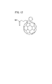
以上のような機能を営む光電変換層における光電変換材料、すなわち、ドナー及びアクセプタの体表的な例としては、特許文献1に示される物質が知られている。具体的には、特許文献1には、ポリ3−ヘキシルチオフェン(P3HT、図11参照)をドナーとし、フェニルC61酪酸メチルエステル(PCBM、図12参照)をアクセプタとする光電変換材料が記載されている。
A substance shown in
ここで、P3HT、PCBMの各々の最高被占軌道(HOMO)及び最低空軌道(LUMO)のエネルギー準位は、図13に示すようになる。上記のようにして光電変換層に光が入射すると、先ず、ドナーであるP3HTのHOMOからLUMOへ電子が遷移する。すなわち、P3HTのHOMOとLUMOとのエネルギー準位差がバンドギャップ(Eg)に対応する。 Here, the energy levels of the highest occupied orbit (HOMO) and the lowest unoccupied orbit (LUMO) of P3HT and PCBM are as shown in FIG. When light enters the photoelectric conversion layer as described above, first, electrons make a transition from HOMO to LUMO of the donor P3HT. That is, the energy level difference between HOMO and LUMO of P3HT corresponds to the band gap (Eg).
P3HTのLUMOに遷移した電子は、次に、アクセプタであるPCBMのLUMOに電子移動することで電子と正孔が発生する。すなわち、P3HTとPCBMのLUMO同士のエネルギー準位差によってエネルギーの損失が生じる。従って、P3HTのHOMOとPCBMのLUMOとのエネルギー準位差が開放電圧(Voc)に対応する。 The electrons that have transitioned to the LUMO of the P3HT then move to the LUMO of the PCBM that is the acceptor, thereby generating electrons and holes. That is, energy loss occurs due to the energy level difference between the LUMOs of P3HT and PCBM. Therefore, the energy level difference between the P3HT HOMO and the PCBM LUMO corresponds to the open circuit voltage (Voc).
ところで、太陽電池では、同一の発電量を得ようとする場合、光電変換効率が大きいものほど面積を小さくすることができる。これにより重量が低減するとともに、設置面積が小さくなるので設置レイアウトの自由度が大きくなるという利点が得られる。これらの理由から、太陽電池の光電変換効率を向上させることが求められている。 By the way, in a solar cell, when it is going to acquire the same electric power generation amount, an area can be made small, so that photoelectric conversion efficiency is large. As a result, the weight is reduced and the installation area is reduced, so that there is an advantage that the degree of freedom of installation layout is increased. For these reasons, it is required to improve the photoelectric conversion efficiency of solar cells.
BHJ太陽電池等の有機薄膜太陽電池において、光電変換効率を向上させるためには、(a)光の吸収量を高め、励起子の生成を活発化する、(b)長波長(近赤外側)の光の吸収を高め、太陽光の利用効率を高める、(c)開放電圧Vocを大きくする等すればよい。そして、これら(a)〜(c)を実現するためには、上述した図13に示す関係からも明らかなように、例えば、ドナーとして、(A)吸光係数が大きく、(B)HOMOとLUMOとのエネルギー準位差(バンドギャップ)が小さく、(C)LUMOのエネルギー準位がアクセプタのLUMOの準位に近い物質を選定することが考えられる。 In order to improve photoelectric conversion efficiency in organic thin-film solar cells such as BHJ solar cells, (a) increase the amount of light absorption and activate exciton generation. (B) long wavelength (near infrared side) (C) Increasing the open-circuit voltage Voc, and the like. And in order to implement | achieve these (a)-(c), as clear from the relationship shown in FIG. 13 mentioned above, for example, as a donor, (A) A large extinction coefficient, (B) HOMO and LUMO It is conceivable to select a substance having a small energy level difference (band gap) with respect to (C) and a LUMO energy level close to the acceptor LUMO level.
上記(A)〜(C)を満足する可能性があるドナーとして、特許文献2〜5に記載される炭素縮合環、すなわち、π電子共役化合物が想起される。なお、この種の炭素縮合環は、「グラフェン」と呼称されるときもある(特許文献4参照)。
As donors that may satisfy the above (A) to (C), the carbon condensed rings described in
特許文献2記載の技術は、ヘキサベンゾコロネン(HBC)に官能基を結合するとともに、この官能基を介して自己集積化させることで、いわゆるナノチューブ状の集積体を得ようとするものである。従って、最終的な半導体を得るための工程数が多く、しかも、得られた集積体がp型(ドナー)であるのか、又はn型(アクセプタ)であるのかが明確ではない。
The technique described in
特許文献3には、HBCの集積体であるナノチューブは、正孔及び電子の伝導経路を同時に有する、との示唆がある。この特許文献3記載の技術は、ナノチューブの内面及び外面をフラーレンで被覆するとともに、その被覆率でHBCにおける正孔移動度を制御するものである。このことから諒解されるように、特許文献2、3記載の技術では、HBCそれ自体のドナーとしての特性を向上させることはできない。
Patent Document 3 suggests that nanotubes, which are HBC aggregates, have hole and electron conduction paths at the same time. In the technique described in Patent Document 3, the inner surface and the outer surface of a nanotube are covered with fullerene, and the hole mobility in HBC is controlled by the coverage. As understood from this, the techniques described in
また、特許文献4記載の技術は、グラフェン誘導体に対し、フッ素原子を有する官能基を結合させ、これにより、n型半導体を得るものである。すなわち、この技術では、アクセプタが得られるに留まり、ドナーを得ることはできない。
In the technique described in
ところで、光電変換材料のアクセプタとして用いることが可能な物質としては、上記のPCBMの他にも、キノイド系やペリレン系等の種々の低分子有機半導体が提案されている。その一例として、図14に示す、7,7,8,8−テトラシアノキノジメタン(TCNQ)、1,4,5,8−ナフタレンテトラカルボン酸二無水物(NTCDA)、ペリレン−3,4,9,10−テトラカルボン酸二無水物(PTCDA)等が挙げられる。 By the way, as a substance that can be used as an acceptor of a photoelectric conversion material, various low molecular organic semiconductors such as a quinoid type and a perylene type have been proposed in addition to the above PCBM. As an example, 7,7,8,8-tetracyanoquinodimethane (TCNQ), 1,4,5,8-naphthalenetetracarboxylic dianhydride (NTCDA), perylene-3,4 shown in FIG. , 9,10-tetracarboxylic dianhydride (PTCDA) and the like.
上記の通り、光電変換材料の光電変換効率を向上させるためには、アクセプタのHOMO及びLUMOのエネルギー準位に応じて、上記(A)〜(C)を満足するようなドナーを選定する必要がある。しかしながら、アクセプタとして用いることが可能な種々の物質のそれぞれに対して、最適なHOMO及びLUMOのエネルギー準位を有するドナーを選定することは容易ではない。すなわち、特許文献2〜5記載の炭素縮合環をドナーとして用いたとしても、上記の種々のアクセプタに対応した最適なエネルギー準位の組み合わせからなる光電変換層を得ることは困難である。その結果、十分な光電変換効率が得られない懸念がある。
As described above, in order to improve the photoelectric conversion efficiency of the photoelectric conversion material, it is necessary to select a donor that satisfies the above (A) to (C) according to the energy levels of the HOMO and LUMO of the acceptor. is there. However, it is not easy to select a donor having optimum HOMO and LUMO energy levels for each of various substances that can be used as acceptors. That is, even if the carbon condensed ring described in
さらに、特許文献2〜5のいずれにおいても、低分子有機化合物が開示されるのみである。周知のように、低分子有機化合物は有機溶媒に溶解し難く、光電変換層を得る際にロールツーロール法等を行うことが困難となるという不具合が顕在化している。また、BHJ太陽電池において、光電変換層を得る際に有機溶媒に溶解し難い低分子有機化合物を用いると、アクセプタドメインとドナードメインとが良好に混在しない懸念がある。その結果、光電変換層における電子及び正孔の移動が促進されず、光電変換効率を十分に向上させることが困難になる。
Furthermore, in any of
本発明は上記した問題を解決するためになされたもので、ドナーあるいはアクセプタとして優れた特性を示し、しかも、光電変換層を簡便且つ高精度に得ることが可能な光電変換材料及びその製造方法と、この光電変換材料を含む光電変換層を具備する有機薄膜太陽電池を提供することを目的とする。 The present invention has been made to solve the above-described problems, and exhibits excellent characteristics as a donor or an acceptor, and further, a photoelectric conversion material capable of easily and highly accurately obtaining a photoelectric conversion layer, and a method for producing the same An object of the present invention is to provide an organic thin film solar cell comprising a photoelectric conversion layer containing this photoelectric conversion material.
前記の目的を達成するために、本発明は、電子を供与する電子供与体あるいは電子を受容する電子受容体として機能する光電変換材料であって、
一般式(1)及び(2)で示すモノマーを重合させて得られるポリフェニレンをさらに反応させた炭素縮合環の重合体からなることを特徴とする。

In order to achieve the above object, the present invention provides a photoelectric conversion material that functions as an electron donor that donates electrons or an electron acceptor that accepts electrons.
It is characterized by comprising a carbon condensed ring polymer obtained by further reacting polyphenylene obtained by polymerizing the monomers represented by the general formulas (1) and (2).
一般式(1)及び(2)で示すモノマーを重合させて得たポリフェニレンをさらに反応させることで、π共役系が拡張された、すなわち、π電子の非局在化の範囲が拡張された炭素縮合環からなる重合体が形成される。以下、この重合体を「ナノグラフェンポリマー」ともいう。なお、ここでの「ポリマー」は、モノマーを繰り返し単位とする低分子及び高分子の総称であり、オリゴマーを含む。 By further reacting the polyphenylene obtained by polymerizing the monomers represented by the general formulas (1) and (2), the π-conjugated system is expanded, that is, the range of delocalization of π electrons is expanded. A polymer consisting of a condensed ring is formed. Hereinafter, this polymer is also referred to as “nanographene polymer”. The “polymer” here is a general term for low molecules and polymers having a monomer as a repeating unit, and includes oligomers.
このナノグラフェンポリマーは、上記の通り、主鎖に沿ってπ電子雲が広がりをもつπ共役系であるため、吸光係数が大きく、励起子が活発に生成される。また、HOMOとLUMOとの間のエネルギー準位差であるバンドギャップが小さく、極大吸収波長が長波長側にシフトし、長波長(近赤外側)の光が良好に吸収される。つまり、太陽光の利用効率を良好に向上させることができる。 Since this nanographene polymer is a π-conjugated system in which a π electron cloud spreads along the main chain as described above, the absorption coefficient is large and excitons are actively generated. In addition, the band gap, which is the energy level difference between HOMO and LUMO, is small, the maximum absorption wavelength is shifted to the long wavelength side, and the light of the long wavelength (near infrared side) is absorbed well. That is, the utilization efficiency of sunlight can be improved favorably.
以上のような理由から、このナノグラフェンポリマーを光電変換材料とする有機薄膜太陽電池の光電変換効率を向上させることができる。 For the reasons described above, the photoelectric conversion efficiency of an organic thin film solar cell using the nanographene polymer as a photoelectric conversion material can be improved.
また、ナノグラフェンポリマーのLUMOのエネルギー準位は、P3HT等に比して低く(深く)なる。従って、例えば、PCBMをアクセプタとし、ナノグラフェンポリマーをドナーとする場合、P3HTをドナーとする場合に比してエネルギー損失が小さくなる。すなわち、ナノグラフェンポリマーを光電変換層のドナーとする有機薄膜太陽電池では、開放電圧Vocが大きくなる。 Further, the LUMO energy level of the nano graphene polymer is lower (deeper) than that of P3HT or the like. Therefore, for example, when PCBM is used as an acceptor and nanographene polymer is used as a donor, energy loss is smaller than when P3HT is used as a donor. That is, in an organic thin film solar cell using a nano graphene polymer as a donor of the photoelectric conversion layer, the open circuit voltage Voc increases.
また、上記の通り、一般式(1)及び(2)で示すモノマーを重合させることによりポリフェニレンが得られる。この際、例えば、重合させるモノマーのモル比や、モノマーの各々の組成及び構造を調整することによって、ポリフェニレンの組成及び構造についても様々に調整することができる。ひいては、ポリフェニレンをさらに反応させて得られるナノグラフェンポリマーの組成及び構造(主鎖骨格に含まれる炭素縮合環の数等)を容易に調整することができる。 Further, as described above, polyphenylene is obtained by polymerizing the monomers represented by the general formulas (1) and (2). At this time, for example, the composition and structure of polyphenylene can be variously adjusted by adjusting the molar ratio of monomers to be polymerized and the composition and structure of each monomer. As a result, the composition and structure (number of carbon condensed rings contained in the main chain skeleton, etc.) of the nano graphene polymer obtained by further reacting polyphenylene can be easily adjusted.
基本的には、ナノグラフェンポリマーの主鎖骨格を構成する炭素縮合環に含まれる二重結合の個数に2を乗じることで、該主鎖骨格に含まれるπ電子(以下、単にπ電子ともいう)の数が算出される。従って、上記のようにナノグラフェンポリマーの組成及び構造を調整することで、π電子の数を所望の値に調整することが可能になる。 Basically, by multiplying the number of double bonds contained in the carbon condensed ring constituting the main chain skeleton of the nanographene polymer by 2, π electrons contained in the main chain skeleton (hereinafter also simply referred to as π electrons) Is calculated. Therefore, by adjusting the composition and structure of the nanographene polymer as described above, the number of π electrons can be adjusted to a desired value.
ナノグラフェンポリマーのバンドギャップはπ電子の数に関連して定まるため、上記のようにπ電子の数を調整することで、該バンドギャップを所望の値に調整することが可能になる。さらに、バンドギャップの値の変化に併せてHOMO及びLUMOのエネルギー準位も変化する。従って、結果的には、π電子の数を調整することで、バンドギャップ、HOMO及びLUMOのエネルギー準位を所望の値に調整することが可能になる。 Since the band gap of the nano graphene polymer is determined in relation to the number of π electrons, the band gap can be adjusted to a desired value by adjusting the number of π electrons as described above. Furthermore, the energy levels of HOMO and LUMO also change with the change of the band gap value. Therefore, as a result, the energy levels of the band gap, HOMO, and LUMO can be adjusted to desired values by adjusting the number of π electrons.
すなわち、種々のアクセプタに対応して、ナノグラフェンポリマーが最適なHOMO及びLUMOのエネルギー準位を有するようにπ電子数を調整することができる。その結果、例えば、PCBMをアクセプタとして用いた場合と同様に、アクセプタとして用いることができる種々の物質に対して、良好な光電変換効率を示すナノグラフェンポリマーをドナーとして提供することが可能になる。なお、ナノグラフェンポリマーをアクセプタとして用いる場合も同様に、種々のドナーに対応して最適な値となるようにHOMO及びLUMOのエネルギー準位を調整することができる。従って、優れた光電変換効率を示す光電変換層を容易に得ることが可能になる。 That is, the number of π electrons can be adjusted so that the nanographene polymer has optimum HOMO and LUMO energy levels corresponding to various acceptors. As a result, for example, as in the case where PCBM is used as an acceptor, a nanographene polymer exhibiting good photoelectric conversion efficiency can be provided as a donor for various substances that can be used as an acceptor. In the case where a nano graphene polymer is used as an acceptor, similarly, the energy levels of HOMO and LUMO can be adjusted so as to have optimum values corresponding to various donors. Therefore, it is possible to easily obtain a photoelectric conversion layer exhibiting excellent photoelectric conversion efficiency.
上記の一般式(2)で示すモノマーとしては、一般式(3)〜(5)の少なくともいずれか1つであることが好ましい。
The monomer represented by the general formula (2) is preferably at least one of the general formulas (3) to (5).
この場合、最終的に得られるナノグラフェンポリマーについて、その主鎖骨格を形成するグラフェン構造部分、すなわち、互いに縮合している炭素環の数を効果的に増大させることができる。その結果、π共役系を一層良好に拡張することができ、主鎖骨格全体にわたって十分にπ電子雲が広がったナノグラフェンポリマーを得ることができる。このようなナノグラフェンポリマーを光電変換材料とすることで、有機薄膜太陽電池の光電変換効率をより良好に向上させることが可能になる。 In this case, in the finally obtained nano graphene polymer, the number of graphene structure portions forming the main chain skeleton, that is, the number of carbocycles condensed with each other can be effectively increased. As a result, the π-conjugated system can be expanded more satisfactorily, and a nanographene polymer in which the π electron cloud is sufficiently spread over the entire main chain skeleton can be obtained. By using such a nano graphene polymer as a photoelectric conversion material, the photoelectric conversion efficiency of the organic thin film solar cell can be improved more favorably.
また、一般式(1)、(2)で示すモノマーが、R1〜R6、R9〜R14の少なくともいずれか一つに、側鎖として上記の可溶性基を備えることが好ましい。この場合、モノマーを重合させて得られるポリフェニレンにも上記の可溶性基が導入されることとなる。上記の側鎖は、ナノグラフェンポリマーを形成するべくポリフェニレンを反応させる際、複数のポリフェニレンの構成単位同士が接近することを抑制する立体障害となる。これによって、複数のポリフェニレンの構成単位同士の炭素環が架橋することを抑制しつつ、各構成単位内の反応(炭素縮合環の形成)を十分に進行させることができる。その結果、主鎖骨格の全体にわたってπ電子雲が十分に広がったナノグラフェンポリマーを容易に得ることができる。 Moreover, it is preferable that the monomer shown by General formula (1), (2) equips at least any one of R1-R6 and R9-R14 with said soluble group as a side chain. In this case, the above-mentioned soluble group is also introduced into polyphenylene obtained by polymerizing the monomer. Said side chain becomes a steric hindrance which suppresses that the structural units of several polyphenylene approach when polyphenylene is made to react in order to form a nano graphene polymer. Thereby, reaction (formation of a carbon condensed ring) in each structural unit can be sufficiently advanced while suppressing the carbocyclic rings of the structural units of the plurality of polyphenylenes from being crosslinked. As a result, a nano graphene polymer in which the π electron cloud is sufficiently spread over the entire main chain skeleton can be easily obtained.
また、このナノグラフェンポリマーは、可溶性基が導入された状態で得られるため、有機溶媒に対するナノグラフェンポリマーの溶解度を高めることができる。これによって、上記の通り太陽光の利用効率を向上させるべく、炭素縮合環の分子量を増大させたナノグラフェンポリマーであっても、有機溶媒に容易に溶解することができる。従って、スピンコート法やロールツーロール法等を用いて光電変換層を簡便且つ高精度に形成することができる。 Moreover, since this nano graphene polymer is obtained in a state in which a soluble group is introduced, the solubility of the nano graphene polymer in an organic solvent can be increased. Thereby, even if it is a nano graphene polymer which increased the molecular weight of a carbon condensed ring in order to improve the utilization efficiency of sunlight as above-mentioned, it can melt | dissolve in an organic solvent easily. Therefore, the photoelectric conversion layer can be easily and highly accurately formed using a spin coating method, a roll-to-roll method, or the like.
上記のナノグラフェンポリマーの構成単位の主鎖骨格に含まれるπ電子の数は、60〜250であることが好ましい。上記の通り、π電子の数を調整し、π共役系の範囲を調整することによって、バンドギャップ(HOMO及びLUMOのエネルギー準位)を調整することができる。従って、π電子の数を60以上とすることで、π共役系を十分に拡張して、光電変換効率に優れたナノグラフェンポリマーを得ることができる。 The number of π electrons contained in the main chain skeleton of the constituent unit of the nano graphene polymer is preferably 60 to 250. As described above, the band gap (HOMO and LUMO energy levels) can be adjusted by adjusting the number of π electrons and adjusting the range of the π conjugated system. Therefore, by setting the number of π electrons to 60 or more, it is possible to sufficiently expand the π conjugated system and obtain a nano graphene polymer excellent in photoelectric conversion efficiency.
また、π電子の数を増大させることは、炭素縮合環の分子量を増大させることになるため、π電子の数を250以下とすることで、有機溶媒等に対して容易に溶解するナノグラフェンポリマーを得ることができる。つまり、ナノグラフェンポリマーのπ電子の数を上記の範囲内とすることで、光電変換効率に優れた光電変換層を、簡便且つ高精度に形成することが可能になる。 In addition, increasing the number of π electrons increases the molecular weight of the carbon condensed ring. Therefore, by setting the number of π electrons to 250 or less, a nano graphene polymer that is easily dissolved in an organic solvent or the like can be obtained. Can be obtained. That is, by setting the number of π electrons of the nanographene polymer within the above range, a photoelectric conversion layer having excellent photoelectric conversion efficiency can be formed easily and with high accuracy.
上記のポリフェニレンの好適な例としては、下記の一般式(6)〜(11)で示す化合物の少なくともいずれか1つを構成単位とするものが挙げられる。
Preferable examples of the above polyphenylene include those having at least one of the compounds represented by the following general formulas (6) to (11) as a structural unit.
なお、一般式(10)で示す化合物は、種々の異性体を含み、その一例として、一般式(12)〜(14)で示す化合物が挙げられる。
In addition, the compound shown by General formula (10) contains various isomers, The compound shown by General formula (12)-(14) is mentioned as the example.
同様に、一般式(11)で示す化合物は、種々の異性体を含み、その一例として、一般式(15)〜(17)で示す化合物が挙げられる。
Similarly, the compound represented by the general formula (11) includes various isomers, and examples thereof include compounds represented by the general formulas (15) to (17).
これらのポリフェニレンは、上記の通りモノマーを重合する際のモル比や、該モノマーの組成及び構造等を調整することによって容易に作成することが可能である。 These polyphenylenes can be easily prepared by adjusting the molar ratio when the monomers are polymerized and the composition and structure of the monomers as described above.
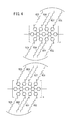
また、上記ポリフェニレンの反応物として、一般式(18)〜(31)で示すグラフェンの少なくともいずれか1つを構成単位とするナノグラフェンポリマーが挙げられる。
In addition, examples of the reaction product of polyphenylene include a nano graphene polymer having at least one of graphene represented by general formulas (18) to (31) as a structural unit.
これらのナノグラフェンポリマーでは、主鎖骨格のグラフェン構造部分が効果的に増大され、π共役系が一層良好に拡張されている。すなわち、主鎖骨格全体にわたって十分にπ電子雲が広がっている。このようなナノグラフェンポリマーを光電変換材料とすることで、有機薄膜太陽電池の光電変換効率をより効果的に向上させることが可能になる。 In these nano graphene polymers, the graphene structure portion of the main chain skeleton is effectively increased, and the π-conjugated system is further improved. That is, the π electron cloud is sufficiently spread over the entire main chain skeleton. By using such a nano graphene polymer as a photoelectric conversion material, it is possible to more effectively improve the photoelectric conversion efficiency of the organic thin film solar cell.
なお、本発明においては、一般式(18)〜(31)に示されるような構成単位がナノメートルスケールであるグラフェンを「ナノグラフェン」ともいう。 In the present invention, graphene whose structural units are represented by the general formulas (18) to (31) is also referred to as “nanographene”.
上記のモノマー、ポリフェニレン、ナノグラフェンポリマーは、側鎖の可溶性基として、直鎖アルキル基、分岐アルキル基、直鎖アルコキシ基、分岐アルコキシ基の少なくともいずれか1つを備えることが好ましい。つまり、一般式(1)に示すモノマーのR1〜R6の少なくとも1つが上記の可溶性基であることが好ましい。また、一般式(3)〜(5)に示すモノマーのR9〜R14の少なくとも1つが上記の可溶性基であることが好ましい。 The monomer, polyphenylene, and nanographene polymer preferably include at least one of a linear alkyl group, a branched alkyl group, a linear alkoxy group, and a branched alkoxy group as a side chain soluble group. That is, it is preferable that at least one of R1 to R6 of the monomer represented by the general formula (1) is the above-described soluble group. Moreover, it is preferable that at least 1 of R9-R14 of the monomer shown to General formula (3)-(5) is said soluble group.
これらのモノマーを重合させて得られるポリフェニレンも上記の可溶性基を有する。すなわち、一般式(6)〜(17)に示す化合物のR15〜R72の少なくとも1つに上記の可溶性基が導入されることになる。また、これらの化合物を構成単位とするポリフェニレンを反応させて得られるナノグラフェンポリマーも上記の可溶性基を有する。すなわち、一般式(18)〜(31)に示すナノグラフェンのR15〜R72の少なくとも1つに上記の可溶性基が導入されることになる。 Polyphenylene obtained by polymerizing these monomers also has the above-mentioned soluble group. That is, the above-mentioned soluble group is introduced into at least one of R15 to R72 of the compounds represented by the general formulas (6) to (17). Moreover, the nano graphene polymer obtained by reacting polyphenylene having these compounds as structural units also has the above-mentioned soluble group. That is, the above-mentioned soluble group is introduced into at least one of R15 to R72 of the nano graphene represented by the general formulas (18) to (31).
なお、側鎖として上記の可溶性基を備えていないモノマーを重合させることで、無置換のポリフェニレンを得た後、該無置換のポリフェニレンに上記の可溶性基を導入することもできる。 In addition, after obtaining the unsubstituted polyphenylene by polymerizing a monomer that does not have the above-described soluble group as a side chain, the above-mentioned soluble group can be introduced into the unsubstituted polyphenylene.
ポリフェニレンが側鎖として上記の可溶性基を備える場合、上述した通り、該可溶性基が立体障害となることで、主鎖骨格の全体にわたってπ電子雲が十分に広がったナノグラフェンポリマーを容易に得ることができる。 When polyphenylene has the above-mentioned soluble group as a side chain, as described above, the soluble group becomes a steric hindrance so that a nano graphene polymer in which the π electron cloud is sufficiently spread over the entire main chain skeleton can be easily obtained. it can.
また、このようにして得られたナノグラフェンポリマーには、上記の可溶性基が側鎖として導入されているため、ナノグラフェンポリマーの有機溶媒に対する溶解度を一層良好に高めることができる。特に、ナノグラフェンポリマーが側鎖の可溶性基として、アルコキシ基を備える場合、一層好ましくは分岐アルコキシ基を備える場合、上記の溶解度を一層良好に高めることができる。 Further, since the above-described soluble group is introduced as a side chain in the nanographene polymer thus obtained, the solubility of the nanographene polymer in an organic solvent can be further improved. In particular, when the nano graphene polymer has an alkoxy group as a side chain soluble group, and more preferably has a branched alkoxy group, the above-described solubility can be further improved.
また、可溶性基が、直鎖アルキル基、分岐アルキル基、直鎖アルコキシ基、分岐アルコキシ基の少なくともいずれか一つである場合、該可溶性基の炭素数は、3〜20であることが好ましい。これによって、光電変換材料として優れた変換効率を示し、且つ良好に有機溶媒に溶解させて容易に成膜可能なナノグラフェンポリマーを効率よく得ることができる。 Moreover, when a soluble group is at least any one of a linear alkyl group, a branched alkyl group, a linear alkoxy group, and a branched alkoxy group, it is preferable that carbon number of this soluble group is 3-20. Thereby, it is possible to efficiently obtain a nano graphene polymer that exhibits excellent conversion efficiency as a photoelectric conversion material and can be easily dissolved into an organic solvent and easily formed into a film.
また、ナノグラフェンポリマーの重合度(構成単位の個数)は、2〜150であることが好ましい。重合度を2以上とすることで、吸光係数を十分に高くすることや、バンドギャップを十分に小さくすることができる。一方、150以下とすることで、重合に要する時間を短縮でき、ナノグラフェンポリマーの生産効率を向上させることができる。すなわち、重合度を上記の範囲内に設定することにより、光電変換材料として優れた特性を示すナノグラフェンポリマーを効率よく得ることができる。 The degree of polymerization (number of structural units) of the nanographene polymer is preferably 2 to 150. By setting the degree of polymerization to 2 or more, the extinction coefficient can be made sufficiently high, and the band gap can be made sufficiently small. On the other hand, by setting it to 150 or less, the time required for the polymerization can be shortened, and the production efficiency of the nano graphene polymer can be improved. That is, by setting the degree of polymerization within the above range, a nano graphene polymer exhibiting excellent characteristics as a photoelectric conversion material can be efficiently obtained.
さらに、本発明は、電子を供与する電子供与体あるいは電子を受容する電子受容体として機能する光電変換材料を製造する方法であって、 Furthermore, the present invention is a method for producing a photoelectric conversion material that functions as an electron donor that donates electrons or an electron acceptor that accepts electrons.
一般式(1)及び(2)で示すモノマーを重合させて、ポリフェニレンを生成する工程と、
前記ポリフェニレンを反応させて、光電変換材料である炭素縮合環の重合体を生成する工程と、
を有することを特徴とする。
A step of polymerizing the monomers represented by the general formulas (1) and (2) to produce polyphenylene;
Reacting the polyphenylene to produce a polymer of a carbon condensed ring that is a photoelectric conversion material;
It is characterized by having.
このような過程を経ることで、π共役系が十分に拡張され、光電変換材料(ドナーあるいはアクセプタ)として優れた機能するナノグラフェンポリマーを容易且つ高精度に得ることができる。すなわち、このナノグラフェンポリマーを光電変換材料とした有機薄膜太陽電池では、光電変換効率を効果的に向上させることが可能になる。 Through such a process, a nanographene polymer that functions sufficiently as a photoelectric conversion material (donor or acceptor) can be easily and highly accurately obtained by sufficiently expanding the π-conjugated system. That is, in the organic thin film solar cell using the nanographene polymer as a photoelectric conversion material, it is possible to effectively improve the photoelectric conversion efficiency.
また、上記のようにして、ポリフェニレンを得る際、一般式(2)で示すモノマーは、一般式(3)〜(5)の少なくとも1つで示すモノマーであることが好ましい。
Moreover, when obtaining polyphenylene as mentioned above, it is preferable that the monomer shown by General formula (2) is a monomer shown by at least 1 of General formula (3)-(5).
このモノマーからポリフェニレンを経て得られたナノグラフェンポリマーでは、その主鎖骨格を形成するグラフェン構造部分を効果的に増大させることができる。すなわち、π共役系が一層良好に拡張され、主鎖骨格全体にわたって十分にπ電子雲が広がったナノグラフェンポリマーを得ることができる。 In the nano graphene polymer obtained from this monomer via polyphenylene, the graphene structure portion forming the main chain skeleton can be effectively increased. That is, it is possible to obtain a nano graphene polymer in which the π-conjugated system is further expanded and the π electron cloud is sufficiently spread over the entire main chain skeleton.
上記のナノグラフェンポリマーを得る際、該ナノグラフェンポリマーの構成単位の主鎖骨格に含まれるπ電子の数を60〜250とすることが好ましい。このπ電子の数は、例えば、重合させるモノマーのモル比や、組成及び構造等を調整することによって調整することができる。π電子の数を60以上とすることで、π共役系を十分に拡張して、光電変換材料として優れた吸光係数、バンドギャップ、極大吸収波長を有するナノグラフェンポリマーを得ることができる。また、π電子の数を250以下とすることで、有機溶媒等に対しても容易に溶解する分子量のナノグラフェンポリマーを得ることができる。 When obtaining said nano graphene polymer, it is preferable that the number of (pi) electrons contained in the principal chain frame | skeleton of the structural unit of this nano graphene polymer shall be 60-250. The number of π electrons can be adjusted, for example, by adjusting the molar ratio of the monomer to be polymerized, the composition, the structure, and the like. By setting the number of π electrons to 60 or more, a π-conjugated system can be sufficiently expanded to obtain a nano graphene polymer having an excellent absorption coefficient, band gap, and maximum absorption wavelength as a photoelectric conversion material. Further, by setting the number of π electrons to 250 or less, a nano graphene polymer having a molecular weight that can be easily dissolved in an organic solvent or the like can be obtained.
上記のモノマーを重合させることで、下記の一般式(6)〜(11)で示す化合物の少なくともいずれか1つを構成単位とするポリフェニレンを得ることが好ましい。
It is preferable to obtain polyphenylene having at least one of the compounds represented by the following general formulas (6) to (11) as a structural unit by polymerizing the above monomers.
なお、一般式(10)で示す化合物の一例としては、一般式(12)〜(14)で示す化合物が挙げられる。つまり、一般式(12)〜(14)で示す化合物は互いに異性体の関係にある。
In addition, as an example of a compound shown by General formula (10), the compound shown by General formula (12)-(14) is mentioned. That is, the compounds represented by the general formulas (12) to (14) are in an isomer relationship with each other.
また、一般式(11)で示す化合物の一例としては、一般式(15)〜(17)で示す化合物が挙げられる。つまり、一般式(15)〜(17)で示す化合物は互いに異性体の関係にある。
In addition, examples of the compound represented by the general formula (11) include compounds represented by the general formulas (15) to (17). That is, the compounds represented by the general formulas (15) to (17) are in an isomer relationship with each other.
そして、上記のポリフェニレンを反応させることで、一般式(18)〜(31)で示すグラフェンの少なくともいずれか1つを構成単位とするナノグラフェンポリマーを得ることが好ましい。
And it is preferable to obtain the nano graphene polymer which makes at least any one of the graphene shown by General formula (18)-(31) a structural unit by making said polyphenylene react.
このようにして得られたナノグラフェンポリマーでは、主鎖骨格のグラフェン構造部分が効果的に増大され、π共役系が一層良好に拡張されている。すなわち、主鎖骨格全体にわたって十分にπ電子雲が広がっている。従って、ナノグラフェンポリマーを光電変換材料とすることで、有機薄膜太陽電池の光電変換効率をより効果的に向上させることが可能になる。 In the nanographene polymer obtained in this manner, the graphene structure portion of the main chain skeleton is effectively increased, and the π-conjugated system is further expanded. That is, the π electron cloud is sufficiently spread over the entire main chain skeleton. Therefore, it becomes possible to improve the photoelectric conversion efficiency of an organic thin-film solar cell more effectively by using a nano graphene polymer as a photoelectric conversion material.
上記のモノマー、ポリフェニレン、ナノグラフェンポリマーは、側鎖の可溶性基として、直鎖アルキル基、分岐アルキル基、直鎖アルコキシ基、分岐アルコキシ基の少なくともいずれか1つを備えることが好ましい。また、これらの可溶性基は、炭素数が3〜20であることが一層好ましい。この場合、可溶性基によって、複数のポリフェニレンの構成単位同士の炭素縮合環が架橋することを抑制でき、主鎖骨格の全体にわたってπ電子雲が十分に広がったナノグラフェンポリマーを容易に得ることが可能になる。また、これらの可溶性基が側鎖として導入されることで、ナノグラフェンポリマーの有機溶媒に対する溶解度を高めることができる。なお、溶解度を高める観点から、特に好ましい可溶性基はアルコキシ基であり、一層好ましくは分岐アルコキシ基である。 The monomer, polyphenylene, and nanographene polymer preferably include at least one of a linear alkyl group, a branched alkyl group, a linear alkoxy group, and a branched alkoxy group as a side chain soluble group. Moreover, it is more preferable that these soluble groups have 3 to 20 carbon atoms. In this case, it is possible to suppress the cross-linking of the carbon condensed rings of the plurality of polyphenylene constituent units by the soluble group, and it is possible to easily obtain a nano graphene polymer in which the π electron cloud is sufficiently spread over the entire main chain skeleton. Become. Moreover, the solubility with respect to the organic solvent of a nano graphene polymer can be improved by introduce | transducing these soluble groups as a side chain. From the viewpoint of increasing the solubility, a particularly preferable soluble group is an alkoxy group, and more preferably a branched alkoxy group.
また、ナノグラフェンポリマーの重合度が2〜150となるように、ポリフェニレンを反応させることが好ましい。このためには、例えば、重合反応時の反応温度や反応時間を、重合度が2〜150となるような条件に設定すればよい。重合度を2以上とすることで、吸光係数を十分に高くすることや、バンドギャップを十分に小さくすることができる。一方、150以下とすることで、重合に要する時間を短縮でき、ナノグラフェンポリマーの生産効率を向上させることができる。 Moreover, it is preferable to make polyphenylene react so that the polymerization degree of a nano graphene polymer may be 2-150. For this purpose, for example, the reaction temperature and reaction time during the polymerization reaction may be set to conditions such that the degree of polymerization is 2 to 150. By setting the degree of polymerization to 2 or more, the extinction coefficient can be made sufficiently high, and the band gap can be made sufficiently small. On the other hand, by setting it to 150 or less, the time required for the polymerization can be shortened, and the production efficiency of the nano graphene polymer can be improved.
さらに、本発明は、前記光電変換材料を用いた有機薄膜太陽電池であって、該光電変換材料を電子供与体として含む光電変換層を具備することを特徴とする。 Furthermore, this invention is an organic thin-film solar cell using the said photoelectric conversion material, Comprising: The photoelectric conversion layer which contains this photoelectric conversion material as an electron donor is comprised, It is characterized by the above-mentioned.
この有機薄膜太陽電池では、例えば、PCBMをアクセプタとしたときのドナーとしてナノグラフェンポリマーを用いることで、P3HTを用いる場合に比して、光電変換層の吸光係数を大きくし、極大吸収波長を長波長側にシフトすることができる。また、ドナーのバンドギャップを小さくすることができる。その上、ドナーのLUMOのエネルギー準位を、アクセプタであるPCBMのLUMOの準位に近くすることができる。 In this organic thin film solar cell, for example, by using a nano graphene polymer as a donor when PCBM is used as an acceptor, the absorption coefficient of the photoelectric conversion layer is increased and the maximum absorption wavelength is increased as compared with the case of using P3HT. Can be shifted to the side. Further, the band gap of the donor can be reduced. Moreover, the energy level of the donor LUMO can be close to the LUMO level of the PCBM that is the acceptor.
従って、この有機薄膜太陽電池では、励起子の生成の活発化、太陽光の利用効率の向上、開放電圧Vocの増大が可能となり、光電変換効率を向上させることができる。 Therefore, in this organic thin film solar cell, the generation of excitons can be activated, the utilization efficiency of sunlight can be increased, and the open circuit voltage Voc can be increased, and the photoelectric conversion efficiency can be improved.
このように光電変換効率が大きな有機薄膜太陽電池では、同一の発電量が得られる太陽電池に比して、その面積を小さくすることができる。従って、重量を低減させることができるため、設置場所に加わる負荷も小さくすることができる。また、設置面積が小さくなるので、設置レイアウトの自由度も向上する。 Thus, in the organic thin film solar cell with large photoelectric conversion efficiency, the area can be made small compared with the solar cell from which the same electric power generation amount is obtained. Therefore, since the weight can be reduced, the load applied to the installation place can also be reduced. Further, since the installation area is reduced, the degree of freedom of the installation layout is also improved.
また、ナノグラフェンポリマーが、上記の可溶性基を備える場合、有機溶媒に対する溶解度が良好に高められる。このため、上記の通り、太陽光の利用効率を向上させるべく炭素縮合環の分子量を増大させたナノグラフェンポリマーであっても、簡便且つ容易に成膜して光電変換層を得ることができる。すなわち、光電変換効率に優れた有機薄膜太陽電池を簡便且つ容易に得ることができる。 Moreover, when a nano graphene polymer is provided with said soluble group, the solubility with respect to an organic solvent is improved favorably. For this reason, as above-mentioned, even if it is a nano graphene polymer which increased the molecular weight of the carbon condensed ring in order to improve the utilization efficiency of sunlight, it can form into a film simply and easily and can obtain a photoelectric converting layer. That is, an organic thin film solar cell excellent in photoelectric conversion efficiency can be obtained easily and easily.
有機薄膜太陽電池の好適な例は、ドナードメインとアクセプタドメインが混在する光電変換層を備えるバルクへテロ接合型のものである。この場合、例えば、ドナーからなる層と、アクセプタからなる層とが個別に形成される平面ヘテロ接合型のものに比して、ドナードメインとアクセプタドメインとの接触面積が大きい。有機薄膜太陽電池では、主にドナードメインとアクセプタドメインの界面で励起子が電子と正孔に分離して発電に関与するので、両者の接触面積が大きいバルクへテロ接合型として構成することにより、光電変換効率を向上させることが可能となる。 A preferred example of the organic thin film solar cell is a bulk heterojunction type including a photoelectric conversion layer in which a donor domain and an acceptor domain are mixed. In this case, for example, the contact area between the donor domain and the acceptor domain is larger than that of a planar heterojunction type in which a donor layer and an acceptor layer are individually formed. In organic thin-film solar cells, excitons are mainly separated into electrons and holes at the interface between the donor domain and the acceptor domain, and are involved in power generation. By configuring as a bulk heterojunction type with a large contact area between the two, Photoelectric conversion efficiency can be improved.
特に分岐アルコキシ基を備えるナノグラフェンポリマーを用いてバルクへテロ接合型の有機薄膜太陽電池の光電変換層を作製する場合、該ナノグラフェンポリマーが有機溶媒に易溶であるため、容易に成膜を行うことができる。これによって、良好に相分離したドナードメインとアクセプタドメインとが互いに混在した光電変換層を得ることができる。すなわち、光電変換層における電荷の分離効率を向上させることができるため、光電変換効率を向上させた有機薄膜太陽電池を得ることができる。 In particular, when a photoelectric conversion layer of a bulk heterojunction type organic thin film solar cell is prepared using a nanographene polymer having a branched alkoxy group, the nanographene polymer is easily soluble in an organic solvent, so that film formation is easily performed. Can do. Thereby, it is possible to obtain a photoelectric conversion layer in which donor domains and acceptor domains that are well phase-separated are mixed with each other. That is, since the charge separation efficiency in the photoelectric conversion layer can be improved, an organic thin film solar cell with improved photoelectric conversion efficiency can be obtained.
本発明によれば、π電子雲の広がりが大きいπ共役系のナノグラフェンポリマーを光電変換材料とするため、吸光係数を大きく、且つバンドギャップ(HOMOとLUMOとのエネルギー準位差)を小さくすることができる。また、極大吸収波長を長波長側にシフトさせて、光の吸収領域を可視光側へ広くすることができる。 According to the present invention, a π-conjugated nanographene polymer with a large π-electron cloud spread is used as a photoelectric conversion material, so that the absorption coefficient is increased and the band gap (difference in energy level between HOMO and LUMO) is reduced. Can do. Further, the absorption region of light can be widened to the visible light side by shifting the maximum absorption wavelength to the long wavelength side.
また、ナノグラフェンポリマーを得る際、主鎖骨格に含まれるπ電子の数を調整することができる。つまり、ナノグラフェンポリマーのバンドギャップ(HOMO及びLUMOのエネルギー準位)を所望の値に調整することができる。このため、HOMOのエネルギー準位が低いドナーとしてナノグラフェンポリマーが得られる。また、PCBMをアクセプタとして用いた場合、ドナー及びアクセプタのLUMOのエネルギー準位を互いに近づけることができる。 Moreover, when obtaining a nano graphene polymer, the number of π electrons contained in the main chain skeleton can be adjusted. That is, the band gap (HOMO and LUMO energy levels) of the nanographene polymer can be adjusted to a desired value. For this reason, a nano graphene polymer is obtained as a donor with a low energy level of HOMO. In addition, when PCBM is used as an acceptor, the LUMO energy levels of the donor and acceptor can be brought close to each other.
すなわち、ナノグラフェンポリマーをドナーとし、PCBMをアクセプタとした光電変換層では、励起子が活発に生成される。また、長波長(近赤外側)の光が良好に吸収されるようになり、太陽光の利用効率が向上する。さらに、開放電圧Vocが大きくなる。その結果、光電変換効率が大きく、小面積で軽量な有機薄膜太陽電池を得ることが可能になる。 That is, excitons are actively generated in a photoelectric conversion layer using a nano graphene polymer as a donor and PCBM as an acceptor. Moreover, the long wavelength (near infrared side) light will be absorbed favorably and the utilization efficiency of sunlight will improve. Further, the open circuit voltage Voc increases. As a result, it is possible to obtain an organic thin-film solar cell having a large photoelectric conversion efficiency and a small area and a light weight.
さらに、PCBM以外の種々の物質をアクセプタとして用いた場合であっても、PCBMをアクセプタとして用いた場合と同様に、良好な光電変換効率を示すナノグラフェンポリマーをドナーとして提供することが可能になる。従って、優れた光電変換効率を示す光電変換層を容易に形成することが可能なナノグラフェンポリマーを得ることができる。 Furthermore, even when various substances other than PCBM are used as an acceptor, it is possible to provide a nanographene polymer exhibiting good photoelectric conversion efficiency as a donor as in the case where PCBM is used as an acceptor. Accordingly, it is possible to obtain a nano graphene polymer that can easily form a photoelectric conversion layer exhibiting excellent photoelectric conversion efficiency.
このナノグラフェンポリマーは、側鎖として可溶性基を備える場合、有機溶媒に一層容易に溶解するようになる。その結果、光電変換層の成膜作業を容易且つ高精度に行うことが可能になり、有機薄膜太陽電池の製造効率及び光電変換効率を良好に向上させることができる。 When this nano graphene polymer has a soluble group as a side chain, the nano graphene polymer is more easily dissolved in an organic solvent. As a result, it becomes possible to perform the film-forming operation | work of a photoelectric converting layer easily and with high precision, and can improve the manufacturing efficiency and photoelectric conversion efficiency of an organic thin film solar cell favorably.
以下、本発明に係る光電変換材料及びその製造方法につき、該光電変換材料を含む光電変換層を具備するバルクヘテロ接合型有機薄膜太陽電池との関係で好適な実施形態を挙げ、添付の図面を参照して詳細に説明する。 Hereinafter, preferred embodiments of the photoelectric conversion material and the manufacturing method thereof according to the present invention will be described in relation to a bulk heterojunction organic thin film solar cell including a photoelectric conversion layer containing the photoelectric conversion material, and refer to the accompanying drawings. And will be described in detail.
図1は、本実施形態に係るバルクヘテロ接合型有機薄膜太陽電池(BHJ太陽電池)10の要部概略縦断面図である。このBHJ太陽電池10は、透明電極12に対し、正孔輸送層14、光電変換層16、裏面電極18が下方からこの順で重畳されることで構成される。
FIG. 1 is a schematic vertical sectional view of an essential part of a bulk heterojunction organic thin film solar cell (BHJ solar cell) 10 according to the present embodiment. The BHJ
透明電極12は、正極として機能する。すなわち、該透明電極12には、正孔24が移動する。なお、透明電極12としては、例えばインジウム−スズ複合酸化物(ITO)等、太陽光をはじめとする光を十分に透過するものが選定される。
The
正孔輸送層14は、光電変換層16にて生成した正孔24が透明電極12に移動することを支援する層である。この正孔輸送層14は、一般的には、ポリスチレンスルホン酸でドープされたポリ(3,4−エチレンジオキシチオフェン)、すなわち、いわゆるPEDOT:PSSから形成することができる。
The
光電変換層16は、電子供与体(ドナー)として作用する光電変換材料からなるドナードメイン26と、電子受容体(アクセプタ)として作用する光電変換材料からなるアクセプタドメイン28とが混在する層として形成されている。この中、アクセプタの好適な例としては、上記のPCBMが挙げられるが、これ以外にも、図14に示す、TCNQ、NTCDA、PTCDAを用いることができる。
The
さらに、2,3,5,6−テトラフルオロ−7,7,8,8−テトラシアノキノジメタン(F4TCNQ)、N,N’−ジペンチル−3,4,9,10−ペリレン−ジカルボキシイミド(PTCDI−C5)、N,N’−ジオクチル−3,4,9,10−ペリレン−ジカルボキシイミド(PTCDI−C8)、N,N’−ジフェニル−3,4,9,10−ペリレン−ジカルボキシイミド(PTCDI−Ph)等をアクセプタとして用いてもよい。 Further, 2,3,5,6-tetrafluoro-7,7,8,8-tetracyanoquinodimethane (F4TCNQ), N, N′-dipentyl-3,4,9,10-perylene-dicarboximide (PTCDI-C5), N, N′-dioctyl-3,4,9,10-perylene-dicarboximide (PTCDI-C8), N, N′-diphenyl-3,4,9,10-perylene-di Carboximide (PTCDI-Ph) or the like may be used as an acceptor.
一方、ドナーとなるp型半導体、すなわち、本実施形態に係る光電変換材料は、一般式(1)及び(2)で示すモノマーを重合させて得られるポリフェニレンをさらに反応させた炭素縮合環の重合体(ナノグラフェンポリマー)からなる。 On the other hand, the p-type semiconductor serving as a donor, that is, the photoelectric conversion material according to the present embodiment, is a compound of a carbon condensed ring obtained by further reacting polyphenylene obtained by polymerizing the monomers represented by the general formulas (1) and (2). It consists of a coalescence (nanographene polymer).
ただし、一般式(1)中のR1〜R6は、それぞれ独立に、水素、若しくは該R1〜R6の全てが水素である場合以外は同一構造であるモノマーよりも有機溶媒に対する溶解性を高める可溶性基を表す。また、一般式(2)中のArは、未置換の若しくは置換された芳香族を表し、R7及びR8は、それぞれ独立に、水素、未置換の若しくは置換された芳香族、メチル基、シリル基のいずれかを表す。 However, R1 to R6 in the general formula (1) are each independently a soluble group that increases the solubility in organic solvents compared to hydrogen or a monomer having the same structure except when all of R1 to R6 are hydrogen. Represents. In the general formula (2), Ar represents an unsubstituted or substituted aromatic group, and R7 and R8 each independently represent hydrogen, an unsubstituted or substituted aromatic group, a methyl group, or a silyl group. Represents one of the following.
この一般式(2)で示すモノマーの好適な例としては、一般式(3)〜(5)で示すものが挙げられる。 Preferable examples of the monomer represented by the general formula (2) include those represented by the general formulas (3) to (5).
ただし、一般式(3)〜(5)中のR9〜R14は、それぞれ独立に、水素、若しくは該R9〜R14の全てが水素である場合以外は同一構造であるモノマーよりも有機溶媒に対する溶解性を高める可溶性基を表す。 However, R9 to R14 in the general formulas (3) to (5) are independently soluble in organic solvents rather than hydrogen or monomers having the same structure except when all of R9 to R14 are hydrogen. Represents a soluble group that enhances
すなわち、一般式(1)で示すモノマーと、一般式(3)〜(5)で示すモノマーの少なくとも1つとを重合させてポリフェニレンを得ることが好ましい。この場合、最終的に得られるナノグラフェンポリマーについて、その主鎖骨格を形成するグラフェン構造部分、すなわち、互いに縮合している炭素環の数を効果的に増大させることができる。 That is, it is preferable to obtain a polyphenylene by polymerizing the monomer represented by the general formula (1) and at least one of the monomers represented by the general formulas (3) to (5). In this case, in the finally obtained nano graphene polymer, the number of graphene structure portions forming the main chain skeleton, that is, the number of carbocycles condensed with each other can be effectively increased.
これらのモノマーを重合させて得られるポリフェニレンとして、一般式(6)〜(11)で示す化合物の少なくともいずれか1つを構成単位とするものが挙げられる。 Examples of the polyphenylene obtained by polymerizing these monomers include those having at least one of the compounds represented by the general formulas (6) to (11) as a structural unit.
ただし、一般式(6)〜(11)中のR15〜R72は、それぞれ独立に、水素、若しくは該R15〜R72の全てが水素である場合以外は同一構造である化合物よりも有機溶媒に対する溶解性を高める可溶性基を表す。 However, R15 to R72 in the general formulas (6) to (11) are each independently more soluble in organic solvents than hydrogen or a compound having the same structure except that all of R15 to R72 are hydrogen. Represents a soluble group that enhances
すなわち、一般式(6)で示す化合物を構成単位とするポリフェニレンは、一般式(1)で示すモノマーと、一般式(3)で示すモノマーとを1:1のモル比で重合させることによって得られる。また、一般式(7)〜(9)で示す化合物を構成単位とするポリフェニレンは互いに異性体であり、一般式(1)、(4)で示すモノマーを1:1のモル比で重合させることによって得られる。さらに、一般式(10)で示す化合物を構成単位とするポリフェニレンは、一般式(1)、(4)、(5)で示すモノマーを2:1:1のモル比で重合させることによって得られる。さらに、一般式(11)で示す化合物を構成単位とするポリフェニレンは、一般式(1)、(4)、(5)で示すモノマーを3:1:2のモル比で重合させることによって得られる。 That is, the polyphenylene having the compound represented by the general formula (6) as a structural unit is obtained by polymerizing the monomer represented by the general formula (1) and the monomer represented by the general formula (3) at a molar ratio of 1: 1. It is done. In addition, polyphenylenes containing the compounds represented by the general formulas (7) to (9) are isomers, and the monomers represented by the general formulas (1) and (4) are polymerized at a molar ratio of 1: 1. Obtained by. Furthermore, the polyphenylene having the compound represented by the general formula (10) as a structural unit is obtained by polymerizing the monomers represented by the general formulas (1), (4), and (5) at a molar ratio of 2: 1: 1. . Furthermore, the polyphenylene having the compound represented by the general formula (11) as a structural unit is obtained by polymerizing the monomers represented by the general formulas (1), (4) and (5) at a molar ratio of 3: 1: 2. .
具体的には、一般式(10)、(11)で示す化合物は複数の異性体を含む。一般式(10)で示す化合物の異性体の一例として、一般式(12)〜(14)で示すものが挙げられる。 Specifically, the compounds represented by the general formulas (10) and (11) include a plurality of isomers. Examples of isomers of the compound represented by the general formula (10) include those represented by the general formulas (12) to (14).
ただし、一般式(12)〜(14)中のR33〜R48は、それぞれ独立に、水素、若しくは該R33〜R48の全てが水素である場合以外は同一構造である化合物よりも有機溶媒に対する溶解性を高める可溶性基を表す。 However, R33 to R48 in general formulas (12) to (14) are each independently more soluble in organic solvents than hydrogen or compounds having the same structure except when all of R33 to R48 are hydrogen. Represents a soluble group that enhances
また、一般式(11)で示す化合物の異性体の一例として、一般式(15)〜(17)で示すものが挙げられる。 Moreover, what is shown by General formula (15)-(17) is mentioned as an example of the isomer of the compound shown by General formula (11).
ただし、一般式(15)〜(17)中のR49〜R72は、それぞれ独立に、水素、若しくは該R49〜R72の全てが水素である場合以外は同一構造である化合物よりも有機溶媒に対する溶解性を高める可溶性基を表す。 However, R49 to R72 in the general formulas (15) to (17) are each independently more soluble in an organic solvent than a compound having the same structure except that hydrogen or all of the R49 to R72 are hydrogen. Represents a soluble group that enhances
なお、一般式(10)、(11)で示す化合物は、一般式(12)〜(14)及び一般式(15)〜(17)で示す化合物に限定されるものではなく、異性体として取り得る全ての化合物を含む。 The compounds represented by the general formulas (10) and (11) are not limited to the compounds represented by the general formulas (12) to (14) and the general formulas (15) to (17). Includes all compounds obtained.
また、ポリフェニレンは、一般式(6)〜(11)で示す化合物のいずれか1つのみが互いに結合したものに限定されることなく、例えば、一般式(6)〜(11)で示す化合物がランダムに結合したものであってもよい。 In addition, polyphenylene is not limited to a compound in which only one of the compounds represented by the general formulas (6) to (11) is bonded to each other. For example, the compounds represented by the general formulas (6) to (11) It may be a random bond.
上記のポリフェニレンをさらに反応させて得られるナノグラフェンポリマーとして、一般式(18)〜(31)で示すナノグラフェンの少なくともいずれか1つを構成単位とするものが挙げられる。 Examples of the nanographene polymer obtained by further reacting the above polyphenylene include those having at least one of the nanographenes represented by the general formulas (18) to (31) as a structural unit.
ただし、一般式(18)〜(31)中のR15〜R72は、それぞれ独立に、水素、若しくは該R15〜R72の全てが水素である場合以外は同一構造であるグラフェンよりも有機溶媒に対する溶解性を高める可溶性基を表す。 However, R15 to R72 in the general formulas (18) to (31) are independently more soluble in organic solvents than graphene having the same structure except that hydrogen or all of R15 to R72 are hydrogen. Represents a soluble group that enhances
すなわち、一般式(18)、(19)で示すナノグラフェンを構成単位とするナノグラフェンポリマーは、一般式(6)で示す化合物を構成単位とするポリフェニレンを反応させることで得られる。同様に、一般式(20)、(21)に係るナノグラフェンポリマーは、それぞれ一般式(7)、(8)に係るポリフェニレンを反応させることで得られる。一般式(22)、(23)に係るナノグラフェンポリマーは、一般式(9)に係るポリフェニレンを反応させることで得られる。一般式(24)、(25)に係るナノグラフェンポリマーは、それぞれ一般式(12)、(13)に係るポリフェニレンを反応させることで得られる。一般式(26)、(27)に係るナノグラフェンポリマーは、一般式(14)に係るポリフェニレンを反応させることで得られる。一般式(28)、(29)に係るナノグラフェンポリマーは、それぞれ一般式(15)、(16)に係るポリフェニレンを反応させることで得られる。一般式(30)、(31)に係るナノグラフェンポリマーは、一般式(17)に係るポリフェニレンを反応させることで得られる。 That is, the nano graphene polymer having nano graphene represented by general formulas (18) and (19) as a structural unit can be obtained by reacting polyphenylene having a compound represented by general formula (6) as a structural unit. Similarly, the nano graphene polymers according to the general formulas (20) and (21) can be obtained by reacting the polyphenylenes according to the general formulas (7) and (8), respectively. The nano graphene polymer according to the general formulas (22) and (23) can be obtained by reacting the polyphenylene according to the general formula (9). The nano graphene polymers according to the general formulas (24) and (25) can be obtained by reacting the polyphenylenes according to the general formulas (12) and (13), respectively. The nano graphene polymer according to the general formulas (26) and (27) can be obtained by reacting the polyphenylene according to the general formula (14). The nano graphene polymers according to the general formulas (28) and (29) can be obtained by reacting the polyphenylenes according to the general formulas (15) and (16), respectively. The nano graphene polymer according to the general formulas (30) and (31) can be obtained by reacting the polyphenylene according to the general formula (17).
なお、ナノグラフェンポリマーは、一般式(18)〜(31)で示すナノグラフェンのいずれか1つのみが互いに結合したものに限定されることなく、例えば、一般式(18)〜(31)で示す化合物がランダムに結合したものであってもよい。
In addition, the nano graphene polymer is not limited to one in which only one of the nano graphenes represented by the general formulas (18) to (31) is bonded to each other, for example, represented by the general formulas (1 8 ) to ( 31 ). A compound in which compounds are randomly bonded may be used.
また、ナノグラフェンポリマーの構成単位は、一般式(18)〜(31)で示すナノグラフェンに限定されない。すなわち、ポリフェニレンが一般式(6)〜(11)で示す化合物が取り得る全ての異性体を構成単位とすることに対応して、該ポリフェニレンを反応させて得られるナノグラフェンポリマーも複数の異性体を含む。
Moreover, the structural unit of the nano graphene polymer is not limited to the nano graphene represented by the general formulas (1 8 ) to ( 31 ). That is, corresponding to the fact that polyphenylene has all the isomers that can be taken by the compounds represented by the general formulas (6) to (11) as a structural unit, the nanographene polymer obtained by reacting the polyphenylene also has a plurality of isomers. Including.
上記の通り、一般式(1)、(2)で表されるモノマーを重合させる際に、モノマーのそれぞれのモル比や、組成及び構造等を調整することで、得られるポリフェニレンの組成及び構造についても調整することが可能である。従って、ポリフェニレンをさらに反応させて得られるナノグラフェンポリマーの組成及び構造(主鎖骨格に含まれる炭素縮合環の数等)を容易に調整することができる。 As described above, when the monomers represented by the general formulas (1) and (2) are polymerized, the composition and structure of the obtained polyphenylene are adjusted by adjusting the molar ratio, composition and structure of each monomer. Can also be adjusted. Therefore, the composition and structure (number of carbon condensed rings contained in the main chain skeleton, etc.) of the nanographene polymer obtained by further reacting polyphenylene can be easily adjusted.
ナノグラフェンポリマーの主鎖骨格に含まれる炭素縮合環中の二重結合の数に応じて、該主鎖骨格に含まれるπ電子の数も変化する。このため、ナノグラフェンポリマーの組成及び構造を調整することで、π電子の数を調整することが可能になる。具体的には、炭素縮合環の二重結合の数に2を乗じることでπ電子の数を算出することができる。従って、一般式(18)、(19)で示すナノグラフェンに含まれるπ電子の数は60である。一般式(20)〜(23)で示すナノグラフェンに含まれるπ電子の数は78である。一般式(24)〜(27)で示すナノグラフェンに含まれるπ電子の数は150である。一般式(28)〜(31)で示すナノグラフェンに含まれるπ電子の数は222である。 Depending on the number of double bonds in the carbon condensed ring contained in the main chain skeleton of the nanographene polymer, the number of π electrons contained in the main chain skeleton also changes. Therefore, the number of π electrons can be adjusted by adjusting the composition and structure of the nanographene polymer. Specifically, the number of π electrons can be calculated by multiplying the number of double bonds of the carbon condensed ring by 2. Therefore, the number of π electrons contained in the nano graphene represented by the general formulas (18) and (19) is 60. The number of π electrons contained in the nano graphene represented by the general formulas (20) to (23) is 78. The number of π electrons contained in the nano graphene represented by the general formulas (24) to (27) is 150. The number of π electrons contained in the nano graphene represented by the general formulas (28) to (31) is 222.
このナノグラフェンポリマーの主鎖骨格に含まれるπ電子は、主鎖骨格の炭素縮合環上に非局在化している。すなわち、このπ電子の数は、π共役系の範囲に対応し、該π電子の数を調整することによって、バンドギャップ(HOMO及びLUMOのエネルギー準位)を調整することができる。つまり、上記のようにπ電子の数を調整することで、ナノグラフェンポリマーのHOMO及びLUMOのエネルギー準位を所望の値に調整することが可能になる。 The π electrons contained in the main chain skeleton of the nanographene polymer are delocalized on the carbon condensed ring of the main chain skeleton. That is, the number of π electrons corresponds to the range of the π conjugated system, and the band gap (HOMO and LUMO energy levels) can be adjusted by adjusting the number of π electrons. That is, by adjusting the number of π electrons as described above, the energy levels of the HOMO and LUMO of the nanographene polymer can be adjusted to desired values.
その結果、例えば、PCBMをアクセプタとして用いた場合と同様に、上記に例示したようなアクセプタとして用いることができる種々の物質に対して、良好な光電変換効率を示すナノグラフェンポリマーをドナーとして提供できる。種々のアクセプタに対応して最適なHOMO及びLUMOのエネルギー準位を有するようにナノグラフェンポリマーのπ電子の数を調整できるためである。 As a result, for example, similarly to the case where PCBM is used as an acceptor, a nanographene polymer exhibiting good photoelectric conversion efficiency can be provided as a donor for various substances that can be used as the acceptor as exemplified above. This is because the number of π electrons of the nanographene polymer can be adjusted so as to have optimum energy levels of HOMO and LUMO corresponding to various acceptors.
なお、ナノグラフェンポリマーをアクセプタとして用いる場合も同様に、種々のドナーに対応して最適な値となるようにバンドギャップ(HOMO及びLUMOのエネルギー準位)を調整することができる。従って、光電変換材料としてのナノグラフェンポリマーの汎用性を向上させることができ、且つ優れた光電変換効率を示す光電変換層を容易に得ることが可能になる。 Similarly, when a nano graphene polymer is used as an acceptor, the band gap (HOMO and LUMO energy levels) can be adjusted so as to be an optimum value corresponding to various donors. Therefore, the versatility of the nano graphene polymer as a photoelectric conversion material can be improved, and a photoelectric conversion layer exhibiting excellent photoelectric conversion efficiency can be easily obtained.
ナノグラフェンポリマーの構成単位の主鎖骨格に含まれるπ電子の数は、60〜250であることが好ましい。π電子の数を増大させるほど、π共役系の範囲を拡張することとなる。従って、π電子の数を60以上とすることで、π共役系を十分に拡張して、光電変換効率に優れたナノグラフェンポリマーを得ることができる。また、π電子の数を増大させることは、炭素縮合環の分子量を増大させることになるため、π電子の数を250以下とすることで、有機溶媒等に対して容易に溶解するナノグラフェンポリマーを得ることができる。 The number of π electrons contained in the main chain skeleton of the constituent unit of the nanographene polymer is preferably 60 to 250. As the number of π electrons is increased, the range of the π conjugated system is expanded. Therefore, by setting the number of π electrons to 60 or more, it is possible to sufficiently expand the π conjugated system and obtain a nano graphene polymer excellent in photoelectric conversion efficiency. In addition, increasing the number of π electrons increases the molecular weight of the carbon condensed ring. Therefore, by setting the number of π electrons to 250 or less, a nano graphene polymer that is easily dissolved in an organic solvent or the like can be obtained. Can be obtained.
つまり、ナノグラフェンポリマーのπ電子の数を上記の範囲内とすることで、光電変換効率に優れた光電変換層を、簡便且つ高精度に形成することが可能になる。 That is, by setting the number of π electrons of the nanographene polymer within the above range, a photoelectric conversion layer having excellent photoelectric conversion efficiency can be formed easily and with high accuracy.
ここで、一般式(6)中のR15〜R24として水素を備える(無置換の)ポリフェニレンから形成されるナノグラフェンポリマーについて説明する。このナノグラフェンポリマーでは、図2(a)に示すように、一つの構成単位内の炭素環同士が全て反応して炭素縮合環が形成されることが好ましい。 Here, the nano graphene polymer formed from (unsubstituted) polyphenylene having hydrogen as R15 to R24 in the general formula (6) will be described. In this nanographene polymer, as shown in FIG. 2 (a), it is preferable that all the carbon rings in one structural unit react to form a carbon condensed ring.
つまり、図2(a)に示すナノグラフェンポリマーでは、図2(b)に示すように、構成単位内に反応していない炭素環が含まれるナノグラフェンポリマーに比べて、π電子雲の広がりを一層良好に得ることができる。また、図2(a)に示すナノグラフェンポリマーでは、図2(c)に示すように、複数の構成単位同士が架橋結合したナノグラフェンポリマーに比べて、有機溶媒に対するナノグラフェンポリマーの溶解度を効果的に高めることができる。すなわち、ナノグラフェンポリマーの溶液を用いた成膜を容易にすることができる。 That is, in the nano graphene polymer shown in FIG. 2 (a), as shown in FIG. 2 (b), the spread of the π electron cloud is further improved as compared with the nano graphene polymer in which the carbocyclic ring not reacting is included in the structural unit. Can get to. Moreover, in the nano graphene polymer shown in FIG. 2A, as shown in FIG. 2C, the solubility of the nano graphene polymer in the organic solvent is effectively increased as compared with the nano graphene polymer in which a plurality of structural units are cross-linked. be able to. That is, film formation using a solution of nanographene polymer can be facilitated.
図2(a)に示すようなナノグラフェンポリマーを容易且つ効率的に得るためには、ポリフェニレンが一般式(6)中のR15〜R24の少なくとも一つに、可溶性基を備えることが好ましい。ここで、可溶性基とは、ポリフェニレンに側鎖として導入されることで、無置換のポリフェニレンよりも、有機溶媒に対する溶解性を高めることができる置換基である。可溶性基として好適には、直鎖アルキル基及び分岐アルキル基(アルキル基)、直鎖アルコキシ基及び分岐アルコキシ基(アルコキシ基)等の置換基が挙げられる。 In order to easily and efficiently obtain a nanographene polymer as shown in FIG. 2A, it is preferable that polyphenylene has a soluble group in at least one of R15 to R24 in the general formula (6). Here, the soluble group is a substituent that can be improved in solubility in an organic solvent as compared with unsubstituted polyphenylene by being introduced into polyphenylene as a side chain. Suitable examples of the soluble group include substituents such as a linear alkyl group and a branched alkyl group (alkyl group), a linear alkoxy group, and a branched alkoxy group (alkoxy group).
このような可溶性基は、例えば、図3に示すように、ポリフェニレンaの構成単位同士の反応において立体障害となる。これによって、該構成単位同士が互いに接近することを抑制できる。その結果、1つの構成単位内における炭素環同士の反応を効果的に進行させることができるため、複数の構成単位間が架橋することを抑制し、十分にπ電子雲が広がったナノグラフェンポリマーを容易且つ効率的に得ることができる。 Such a soluble group becomes a steric hindrance in the reaction between structural units of polyphenylene a, for example, as shown in FIG. Thereby, it can suppress that this structural unit approaches mutually. As a result, since the reaction between carbocycles in one structural unit can be effectively advanced, it is possible to suppress cross-linking between a plurality of structural units and to facilitate a nanographene polymer with a sufficiently expanded π electron cloud. And can be obtained efficiently.
なお、図3に例示のポリフェニレンaでは、一般式(6)中のR17、R19、R20、R22にアルコキシ基(OC10H21)が導入され、R23及びR24にアルキル基(C12H25)が導入され、R15及びR16にアルキル基(CH3)が導入されている。なお、導入される可溶性基の種類や配置は、上記に限定されるものではない。
In the polyphenylene a illustrated in FIG. 3, an alkoxy group (OC 10 H 21 ) is introduced into R17, R19, R20, and R22 in the general formula (6), and an alkyl group (C 12 H is introduced into R2 3 and
また、図4に示すように、一般式(7)で示す化合物を構成単位とするポリフェニレンbについても、一般式(6)と同様に、可溶性基が導入されることで、複数の構成単位同士の間で反応が生じることを抑制できる。 Moreover, as shown in FIG. 4, also about polyphenylene b which uses the compound shown by General formula (7) as a structural unit, a soluble group is introduce | transduced similarly to General formula (6), and several structural units are mutually connected. It can suppress that reaction arises between.
図4に例示のポリフェニレンbは、一般式(7)中のR25〜R32にアルコキシ基としてOC10H21が導入された化合物を構成単位とする。 The polyphenylene b illustrated in FIG. 4 includes a compound in which OC 10 H 21 is introduced as an alkoxy group in R25 to R32 in the general formula (7).
可溶性基が導入されたポリフェニレンは、例えば、一般式(1)、(3)〜(5)に示すモノマーのR1〜R6、R9〜R14の少なくとも1つに可溶性基を導入することで得ることができる。 The polyphenylene introduced with a soluble group can be obtained, for example, by introducing a soluble group into at least one of R1 to R6 and R9 to R14 of the monomers represented by the general formulas (1) and (3) to (5). it can.
なお、例えば、可溶性基としてアルキル基を有するポリフェニレンを得る場合等については、予めモノマーに可溶性基が導入されていなくてもよい。すなわち、無置換(一般式(1)及び(3)〜(5)中のR1〜R6及びR9〜R14がいずれも水素)のモノマーから無置換のポリフェニレンを得た後、該ポリフェニレンにアルキル基を導入することも可能である。 For example, in the case of obtaining a polyphenylene having an alkyl group as a soluble group, the soluble group may not be introduced into the monomer in advance. That is, after obtaining unsubstituted polyphenylene from an unsubstituted monomer (wherein R1 to R6 and R9 to R14 in general formulas (1) and (3) to (5) are all hydrogen), an alkyl group is added to the polyphenylene. It is also possible to introduce.
上記の通り、側鎖として可溶性基が導入されたポリフェニレンを反応させてナノグラフェンポリマーを得る場合、該ナノグラフェンポリマーにも可溶性基が導入される。つまり、一般式(18)〜(31)に示すナノグラフェンのR15〜R72の少なくとも1つに上記の可溶性基が導入されることになる。これによって、ナノグラフェンポリマーを有機溶媒に対して易溶とすることができる。 As described above, when a nanographene polymer is obtained by reacting polyphenylene having a soluble group introduced as a side chain, a soluble group is also introduced into the nanographene polymer. That is, the above-described soluble group is introduced into at least one of R15 to R72 of the nano graphene represented by the general formulas (18) to (31). Thereby, the nano graphene polymer can be easily dissolved in an organic solvent.
なお、ナノグラフェンポリマーの溶解度を向上させる観点からは、ポリフェニレンが側鎖としてアルコキシ基を備えることが好ましく、特に好ましくは分岐アルコキシ基である。この場合、上記溶解度を一層効果的に高めることができる。 In addition, from the viewpoint of improving the solubility of the nanographene polymer, it is preferable that polyphenylene has an alkoxy group as a side chain, and a branched alkoxy group is particularly preferable. In this case, the solubility can be increased more effectively.
アルキル基及びアルコキシ基としては、炭素数が3〜20個であるものが好ましい。アルコキシ基の炭素数を上記の範囲とすることで、ポリフェニレンの構成単位同士の接近を抑制しつつ、ナノグラフェンポリマーの有機溶媒に対する溶解性を向上させることができる。すなわち、光電変換材料として優れた特性を示し、且つ有機溶媒に易溶であり良好に成膜することが可能なナノグラフェンポリマーを効率よく得ることができる。 As the alkyl group and alkoxy group, those having 3 to 20 carbon atoms are preferable. By setting the number of carbon atoms of the alkoxy group within the above range, the solubility of the nanographene polymer in an organic solvent can be improved while suppressing the approach between the structural units of polyphenylene. That is, it is possible to efficiently obtain a nanographene polymer that exhibits excellent characteristics as a photoelectric conversion material, is easily soluble in an organic solvent, and can be formed into a good film.
また、ナノグラフェンポリマーの重合度は、2〜150であることが好ましい。重合度を2以上、すなわち、互いに結合したナノグラフェンの個数nを2個以上とすることによって、吸光係数を大きくすることができる。また、重合度を150以下、すなわち、互いに結合したナノグラフェンの個数nを150個以下とすることによって、ナノグラフェンポリマーを得るまでの重合に要する時間を短縮して、生産効率を向上させることができる。従って、重合度を上記の範囲に設定することで、吸光係数が十分に向上した光電変換材料を効率よく作製することができる。 Moreover, it is preferable that the polymerization degree of a nano graphene polymer is 2-150. The extinction coefficient can be increased by setting the degree of polymerization to 2 or more, that is, the number n of nanographene bonded to each other is 2 or more. In addition, by setting the degree of polymerization to 150 or less, that is, the number n of nanographene bonded to each other is 150 or less, it is possible to shorten the time required for polymerization to obtain a nanographene polymer and improve production efficiency. Therefore, by setting the degree of polymerization within the above range, a photoelectric conversion material having a sufficiently improved extinction coefficient can be efficiently produced.
BHJ太陽電池10(図1参照)においては、このようなナノグラフェンポリマーからなる光電変換材料を含む光電変換層16上に、裏面電極18が重畳される。この裏面電極18は、電子30が到達する負極として機能する。なお、光電変換層16と裏面電極18の間には、バトクプロインやフッ化リチウム等からなる電子輸送層(不図示)を介在させてもよい。これによって、光電変換層16にて生成した電子30が裏面電極18に移動することを促進させることができる。
In the BHJ solar cell 10 (see FIG. 1), the
本実施形態に係るBHJ太陽電池10は、基本的には以上のように構成されるものであり、次に、その作用効果につき説明する。
The BHJ
BHJ太陽電池10の透明電極12に光(例えば、太陽光)が照射されると、該光は、正孔輸送層14を通過して光電変換層16に到達する。その結果、該光電変換層16において、励起子32が生成する。
When light (for example, sunlight) is irradiated onto the
生成した励起子32は、ドナードメイン26内を移動して、該ドナードメイン26とアクセプタドメイン28との界面に到達する。そして、この界面において、電子30と正孔24に分離する。上記と同様に、この中の電子30は、アクセプタドメイン28内を移動し、電子輸送層を経由した後、負極である裏面電極18に到達する。一方、正孔24は、ドナードメイン26内を移動し、正孔輸送層14を経由した後、正極である透明電極12に到達する。
The generated
ここで、本実施形態では、光電変換層16中のドナードメイン26が、一般式(16)〜(29)で示すナノグラフェンの少なくともいずれか1つを構成単位とするナノグラフェンポリマー(光電変換材料)からなる。
Here, in this embodiment, the
一般式(18)〜(31)から諒解される通り、ナノグラフェンにおいては、その全体にπ電子雲が広がっている。ドナードメイン26は、このナノグラフェンを構成単位とするナノグラフェンポリマーからなる。つまり、ドナードメイン26では、ナノグラフェン単体(モノマー)からなる場合に比して、π電子雲がより一層広範囲にわたって広がっている。
As understood from the general formulas (18) to (31), in the nano graphene, a π electron cloud spreads over the whole. The
このようにπ電子雲の広がりが大きいドナードメイン26では、極大吸収波長が長波長側にシフトするとともに吸光係数が大きくなる。すなわち、HOMO−LUMO間のエネルギー準位差に相当するバンドギャップが小さくなる。従って、ドナードメイン26において、励起子32の生成が活発となるとともに、太陽光の利用効率が向上する。
Thus, in the
さらに、このナノグラフェンポリマーを得る際、主鎖骨格に含まれるπ電子の数を調整することができる。すなわち、ナノグラフェンポリマーのバンドギャップ(HOMO及びLUMOのエネルギー準位)を所望の値に調整することができる。これによって、ナノグラフェンポリマーをドナーとして用いる場合では、アクセプタとして用いる物質に応じて、HOMO及びLUMOのエネルギー準位を適切な値に調整することができる。その結果、優れた光電変換効率を示す光電変換層16を容易に得ることが可能になる。
Furthermore, when obtaining this nano graphene polymer, the number of π electrons contained in the main chain skeleton can be adjusted. That is, the band gap (HOMO and LUMO energy levels) of the nanographene polymer can be adjusted to a desired value. Accordingly, when the nano graphene polymer is used as a donor, the energy levels of HOMO and LUMO can be adjusted to appropriate values depending on the substance used as an acceptor. As a result, it is possible to easily obtain the
さらに、このナノグラフェンポリマーは、側鎖として可溶性基を備える場合、有機溶媒に一層容易に溶解するようになる。その結果、光電変換層16の成膜作業を容易且つ高精度に行うことが可能になり、BHJ太陽電池10の製造効率及び光電変換効率を良好に向上させることができる。
Furthermore, when this nano graphene polymer is provided with a soluble group as a side chain, the nano graphene polymer is more easily dissolved in an organic solvent. As a result, the film forming operation of the
このため、BHJ太陽電池10では、同一の発電量が得られる他の太陽電池に比して面積を小さくすることができる。従って、重量が低減するので設置場所に加わる負荷が小さくなり、また、設置レイアウトの自由度が向上する。
For this reason, in BHJ
次に、本実施形態に係る光電変換材料の製造方法、すなわち、ナノグラフェンポリマーの製造方法について説明する。 Next, the manufacturing method of the photoelectric conversion material which concerns on this embodiment, ie, the manufacturing method of a nano graphene polymer, is demonstrated.
上記した通り、本実施形態に係るナノグラフェンポリマーは、一般式(1)、(2)で示すモノマーを重合させて得られたポリフェニレンの反応生成物として得ることができる。以下、図3に示すポリフェニレンaを反応させて、ナノグラフェンポリマーaを得る場合を例に挙げて説明する。 As described above, the nanographene polymer according to the present embodiment can be obtained as a reaction product of polyphenylene obtained by polymerizing the monomers represented by the general formulas (1) and (2). Hereinafter, the case of obtaining the nanographene polymer a by reacting the polyphenylene a shown in FIG. 3 will be described as an example.
先ず、ポリフェニレンaを得るべく、アルコキシ基(OC10H21)を導入したジベンジルケトンを形成する。具体的には、反応式(32)で示すように、4−ヒドロキシベンゼン酢酸メチルと1−ヨードデカンとを反応させて4−デシルオキシベンゼン酢酸メチルを得る。 First, in order to obtain polyphenylene a, a dibenzyl ketone into which an alkoxy group (OC 10 H 21 ) has been introduced is formed. Specifically, as shown in the reaction formula (32), methyl 4-hydroxybenzeneacetate and 1-iododecane are reacted to obtain methyl 4-decyloxybenzeneacetate.
そして、反応式(33)で示すように、4−デシルオキシベンゼン酢酸メチルに、リチウムジイソプロピルアミド(LDA)を加え、これによって得られる中間生成物にさらに塩酸を加える。その結果、アルコキシ基を導入したジベンジルケトンとして、1,3−ジデシルオキシベンゼン−2−プロパノンを形成することができる。 Then, as shown in the reaction formula (33), lithium diisopropylamide (LDA) is added to methyl 4-decyloxybenzeneacetate, and hydrochloric acid is further added to the intermediate product obtained thereby. As a result, 1,3-didecyloxybenzene-2-propanone can be formed as dibenzyl ketone having an alkoxy group introduced.
次に、1,3−ジデシルオキシベンゼン−2−プロパノンと、1,4−ビスベンジルとからアルコキシ基を備える3,3’−(1,4−フェニレン)ビス(2,4,5,−トリフェニル−2,4−シクロペンタジエン−1−オン)a(一般式(1)で示すモノマー)を得る。具体的には、反応式(34)で示すように、1,3−ジデシルオキシベンゼン−2−プロパノン、1,4−ビスベンジル、n−ブタノールを混合した溶液を加熱しながら、TritonBのメタノール溶液を添加する。なお、TritonBは、水酸化ベンジルトリメチルアンモニウムである。これによって、3,3’−(1,4−フェニレン)ビス(2,4,5,−トリフェニル−2,4−シクロペンタジエン−1−オン)aを得ることができる。
Next, 3,3 ′-(1,4-phenylene) bis (2,4,5, -triphenyl) having an alkoxy group from 1,3-didecyloxybenzene-2-propanone and 1,4-bisbenzyl. Phenyl-2,4-cyclopentadien-1-one) a (monomer represented by the general formula (1)) is obtained. Specifically, as shown in the reaction formula (34), while heating a solution in which 1,3-didecyloxybenzene-2-propanone, 1,4-bisbenzyl and n-butanol are mixed, a Triton B methanol solution Add. Triton B is benzyltrimethylammonium hydroxide. Thereby, 3,3 ′-(1,4-phenylene) bis (2,4,5, -triphenyl-2,4-cyclopentadien-1-one) a can be obtained.
次に、反応式(35)で示すように、上記の通り得られた3,3’−(1,4−フェニレン)ビス(2,4,5,−トリフェニル−2,4−シクロペンタジエン−1−オン)aと、1,4−ジエチニル−2,5−ジドデシルベンゼン(一般式(3)で示すモノマー)をディールスアルダー重合させる。これによって、ポリフェニレンaを得ることができる。この際、アルコキシ基を備える3,3’−(1,4−フェニレン)ビス(2,4,5,−トリフェニル−2,4−シクロペンタジエン−1−オン)aと、アルキル基を備える1,4−ジエチニル−2,5−ジドデシルベンゼンとを反応させることによって、効率的にポリフェニレンaを得ることができる。また、ポリフェニレンaにアルコキシ基及びアルキル基の両方を導入することが可能になり、有機溶媒に対するポリフェニレンaの可溶性を一層高めることができる。
Next, as shown in the reaction formula (35), 3,3 ′-(1,4-phenylene) bis (2,4,5, -triphenyl-2,4-cyclopentadiene-) obtained as described above was obtained. 1-one) A and 1,4-diethynyl-2,5-didodecylbenzene (monomer represented by the general formula (3)) are subjected to Diels-Alder polymerization. Thereby, polyphenylene a can be obtained. At this time, 3,3 ′-(1,4-phenylene) bis (2,4,5, -triphenyl-2,4-cyclopentadien-1-one) a having an alkoxy group and 1 having an alkyl group , 4-diethynyl-2,5-didodecylbenzene can be reacted efficiently to obtain polyphenylene a. Moreover, it becomes possible to introduce | transduce both an alkoxy group and an alkyl group into polyphenylene a, and can further improve the solubility of polyphenylene a with respect to an organic solvent.
上記のようにして得られたポリフェニレンaを、例えば、反応式(36)で示すように、塩化鉄(FeCl3)等のルイス酸触媒を用いて反応させる。その結果、上記のアルコキシ基及びアルキル基が導入されたナノグラフェンポリマーaが得られる。具体的には、このナノグラフェンポリマーaには構造異性体が含まれる。従って、一般式(18)又は(19)のR17、R19、R20、R22にOC10H21が導入され、R23及びR24にC12H25が導入され、R15及びR16にCH3が導入されたナノグラフェンポリマーaを得ることができる。 The polyphenylene a obtained as described above is reacted using a Lewis acid catalyst such as iron chloride (FeCl 3 ), for example, as shown in the reaction formula (36). As a result, the nano graphene polymer a into which the above alkoxy group and alkyl group are introduced is obtained. Specifically, the nanographene polymer a contains structural isomers. Therefore, OC 10 H 21 was introduced into R17, R19, R20, and R22 of general formula (18) or (19), C 12 H 25 was introduced into R23 and R24, and CH 3 was introduced into R15 and R16. Nano graphene polymer a can be obtained.
次に、図4に示すポリフェニレンbを反応させて、ナノグラフェンポリマーbを得る場合を例に挙げて説明する。 Next, the case of obtaining the nano graphene polymer b by reacting the polyphenylene b shown in FIG. 4 will be described as an example.
なお、ポリフェニレンbと構造異性体の関係にある一般式(8)、(9)に係るポリフェニレンも、ポリフェニレンbと同様にして得られることは勿論である。また、ポリフェニレンbからナノグラフェンポリマーbを得る場合と同様に、一般式(8)、(9)に係るポリフェニレンから、一般式(20)〜(23)に係るナノグラフェンポリマーを得ることができる。 Needless to say, the polyphenylenes represented by the general formulas (8) and (9), which are in a structural isomer relationship with polyphenylene b, can also be obtained in the same manner as polyphenylene b. Similarly to the case of obtaining the nanographene polymer b from the polyphenylene b, the nanographene polymer according to the general formulas (20) to (23) can be obtained from the polyphenylene according to the general formulas (8) and (9).
先ず、ポリフェニレンbを得るべく、アルコキシ基(OC10H21)を導入したジベンジルケトンと、アルコキシ基(OC10H21)を導入した1,4−ビスベンジルとを形成する。 First, to obtain a polyphenylene b, forming a dibenzyl ketone was introduced alkoxy group (OC 10 H 21), and a 1,4 Bisubenjiru introduced an alkoxy group (OC 10 H 21).
具体的には、先ず、上記の反応式(32)、(33)で示す反応を経て、アルコキシ基を導入したジベンジルケトンを得る。 Specifically, first, dibenzyl ketone having an alkoxy group introduced is obtained through the reactions shown in the above reaction formulas (32) and (33).
これとは別に、アルコキシ基を導入した1,4−ビスベンジルを形成するべく、先ず、反応式(37)で示すように、ヨードフェノールとブロモデカンとを反応させて、1−デキシルオキシ−4−ヨードベンゼンを得る。 Separately, in order to form 1,4-bisbenzyl having an alkoxy group introduced, first, as shown in the reaction formula (37), iodophenol and bromodecane are reacted to give 1-dexyloxy-4-iodobenzene. Get.
次に、反応式(38)で示すように、1−デキシルオキシ−4−ヨードベンゼンと、1,4−ジエチニルベンゼンとを反応させて、1,4−ビス(デシルオキシフェニルエチニル)ベンゼンを得る。 Next, as shown in the reaction formula (38), 1-dexyloxy-4-iodobenzene and 1,4-diethynylbenzene are reacted to obtain 1,4-bis (decyloxyphenylethynyl) benzene. .
次に、反応式(39)で示すように、パラジウム(Pd)錯体等を触媒に用いて、1,4−ビス(デシルオキシフェニルエチニル)ベンゼンを酸化反応させることでアルコキシ基を導入した1,4−ビスベンジルを得る。 Next, as shown in the reaction formula (39), 1,4-bis (decyloxyphenylethynyl) benzene was subjected to an oxidation reaction using a palladium (Pd) complex or the like as a catalyst. 4-Bisbenzyl is obtained.
上記のように形成した、1,3−ジデシルオキシベンゼン−2−プロパノンと、アルコキシ基を導入した1,4−ビスベンジルとを反応させる。すなわち、反応式(40)で示すように、1,3−ジデシルオキシベンゼン−2−プロパノン、アルコキシ基を導入した1,4−ビスベンジル、n−ブタノールを混合した溶液を加熱しながら、TritonBのメタノール溶液を添加する。これによって、アルコキシ基を備える3,3’−(1,4−フェニレン)ビス(2,4,5,−トリフェニル−2,4−シクロペンタジエン−1−オン)b(一般式(1)で示すモノマー)を得ることができる。
1,3-didecyloxybenzene-2-propanone formed as described above is reacted with 1,4-bisbenzyl introduced with an alkoxy group. That is, as shown in the reaction formula (40), while heating a solution in which 1,3-didecyloxybenzene-2-propanone, 1,4-bisbenzyl having an alkoxy group introduced, and n-butanol were mixed, Triton B was heated. Add methanol solution. Thereby, 3,3 ′-(1,4-phenylene) bis (2,4,5, -triphenyl-2,4-cyclopentadien-1-one) b having an alkoxy group (in the general formula (1)) Monomer) shown.
そして、反応式(41)で示すように、3,3’−(1,4−フェニレン)ビス(2,4,5,−トリフェニル−2,4−シクロペンタジエン−1−オン)bと、4,4’−ビス(デシルオキシフェニルエチニル)ビフェニル(一般式(4)で示すモノマー)とをディールスアルダー重合させる。これによって、ポリフェニレンbを得ることができる。
And, as shown in the reaction formula (41), 3,3 ′-(1,4-phenylene) bis (2,4,5, -triphenyl-2,4-cyclopentadien-1-one) b, Diels-Alder polymerization of 4,4′-bis (decyloxyphenylethynyl) biphenyl (monomer represented by the general formula (4)) is performed. Thereby, polyphenylene b can be obtained.
なお、上記の4,4’−ビス(デシルオキシフェニルエチニル)ビフェニルは、以下のようにして得ることができる。すなわち、先ず、上記の反応式(37)で示すように、ヨードフェノールとブロモデカンとを反応させて、1−デキシルオキシ−4−ヨードベンゼンを得る。 The above 4,4'-bis (decyloxyphenylethynyl) biphenyl can be obtained as follows. That is, first, as shown in the above reaction formula (37), iodophenol and bromodecane are reacted to obtain 1-dexyloxy-4-iodobenzene.
そして、反応式(42)で示すように、1−デキシルオキシ−4−ヨードベンゼンと、4,4’−ジエチニルビフェニルとを溶媒中、触媒存在下で反応させる。ここで、溶媒としては、テトラヒドロフラン(THF:C4H8O)を用いることができる。また、触媒としては、ビス(トリフェニルホスフィン)パラジウム(II)ジクロリド((Ph3P)2PbCl2)と、ヨウ化銅(CuI)と、ジエチルアミン(Et2NH)とを用いることができる。これによって、4,4’−ビス(デシルオキシフェニルエチニル)ビフェニルが形成される。 Then, as shown in the reaction formula (42), 1-dexyloxy-4-iodobenzene and 4,4′-diethynylbiphenyl are reacted in a solvent in the presence of a catalyst. Here, tetrahydrofuran (THF: C 4 H 8 O) can be used as the solvent. As the catalyst, bis (triphenylphosphine) palladium (II) dichloride ((Ph 3 P) 2 PbCl 2 ), copper iodide (CuI), and diethylamine (Et 2 NH) can be used. This forms 4,4′-bis (decyloxyphenylethynyl) biphenyl.
上記のようにして得られたポリフェニレンbを、例えば、反応式(43)で示すように、塩化鉄(FeCl3)等のルイス酸触媒を用いて反応させる。その結果、ナノグラフェンポリマーbを得ることができる。すなわち、このナノグラフェンポリマーbは、一般式(20)中のR25〜R32にOC10H21が導入されたナノグラフェンを構成単位とする。 The polyphenylene b obtained as described above is reacted using a Lewis acid catalyst such as iron chloride (FeCl 3 ), for example, as shown in the reaction formula (43). As a result, the nano graphene polymer b can be obtained. That is, the nano graphene polymer b includes nano graphene in which OC 10 H 21 is introduced into R25 to R32 in the general formula (20).
上記の通り、ポリフェニレンa、bには、可溶性基が導入されているため、複数の構成単位間のカップリング(分子間カップリング)が抑制される。従って、例えば、触媒としての塩化鉄の量を調整することで、構成単位内の炭素環を全て反応させつつ、複数の構成単位間に架橋構造が形成されることを抑制できる。これによって、構成単位全体にわたって十分にπ電子雲が広がった炭素縮合環からなるナノグラフェンポリマーa、bを得ることができる。つまり、この炭素縮合環に非局在化しているπ電子の数は、ナノグラフェンポリマーaの主鎖骨格の構成単位中では60であり、ナノグラフェンポリマーbの主鎖骨格の構成単位中では78である。 As above-mentioned, since the soluble group is introduce | transduced into polyphenylene a and b, the coupling (intermolecular coupling) between several structural units is suppressed. Therefore, for example, by adjusting the amount of iron chloride as a catalyst, it is possible to suppress the formation of a crosslinked structure between a plurality of structural units while reacting all the carbocycles in the structural units. As a result, nanographene polymers a and b composed of a carbon condensed ring in which a π electron cloud is sufficiently spread over the entire structural unit can be obtained. That is, the number of π electrons delocalized in the carbon condensed ring is 60 in the structural unit of the main chain skeleton of the nanographene polymer a, and is 78 in the structural unit of the main chain skeleton of the nanographene polymer b. .
このように、一般式(1)、(2)で表されるモノマーの重合比、組成及び構造等を調整することによって、ナノグラフェンポリマーのπ電子の数(主鎖骨格に含まれる炭素縮合環の二重結合の数)を容易に調整することができる。 Thus, by adjusting the polymerization ratio, composition and structure of the monomers represented by the general formulas (1) and (2), the number of π electrons of the nanographene polymer (the number of carbon condensed rings included in the main chain skeleton) The number of double bonds) can be easily adjusted.
また、ナノグラフェンポリマーの重合度は、例えば、モノマーの比率や、重合反応時の反応時間や反応温度を設定することで調整可能であり、上記したように2〜150とすることが好ましい。これによって、吸光係数が十分に向上した光電変換材料(ナノグラフェンポリマー)を効率よく作製することができる。 In addition, the degree of polymerization of the nanographene polymer can be adjusted, for example, by setting the monomer ratio, the reaction time and the reaction temperature during the polymerization reaction, and is preferably 2 to 150 as described above. Thereby, a photoelectric conversion material (nanographene polymer) having a sufficiently improved absorption coefficient can be efficiently produced.
図5は、上記のポリフェニレンa及びナノグラフェンポリマーaの1H−核磁気共鳴(NMR)スペクトルである。スペクトル中、0〜2ppmに現れているピークは、アルコキシ基の水素に由来している。また、6〜8ppmに現れているピークは、フェニル基の水素に由来している。 FIG. 5 is a 1 H-nuclear magnetic resonance (NMR) spectrum of the above polyphenylene a and nanographene polymer a. In the spectrum, the peak appearing at 0 to 2 ppm is derived from the hydrogen of the alkoxy group. Moreover, the peak which appears in 6-8 ppm originates in the hydrogen of a phenyl group.
図5から、ポリフェニレンaのスペクトル中に出現しているアルコキシ基の水素に由来するピークは、ナノグラフェンポリマーaのスペクトル中にも出現していることが分かる。すなわち、上記のように、アルコキシ基を備えるポリフェニレンaを反応させることで、該アルコキシ基を備えるナノグラフェンポリマーaが生成されていると判断し得る。 FIG. 5 shows that the peak derived from the hydrogen of the alkoxy group appearing in the spectrum of polyphenylene a also appears in the spectrum of the nanographene polymer a. That is, as described above, it can be determined that the nanographene polymer a having an alkoxy group is produced by reacting the polyphenylene a having an alkoxy group.
また、フェニル基の水素に由来するピークは、ポリフェニレンaのスペクトル中には出現しているが、ナノグラフェンポリマーaのスペクトル中には出現していない。このため、上記のように得られたナノグラフェンポリマーaでは、ポリフェニレンaの構成単位内のフェニル基が互いに反応して炭素縮合環が形成されていること、つまり、ナノグラフェンポリマーaのπ共役系が十分に拡張されていることが分かる。 Moreover, although the peak derived from the hydrogen of a phenyl group has appeared in the spectrum of polyphenylene a, it has not appeared in the spectrum of nano graphene polymer a. Therefore, in the nanographene polymer a obtained as described above, the phenyl groups in the structural unit of polyphenylene a react with each other to form a carbon condensed ring, that is, the π-conjugated system of the nanographene polymer a is sufficient. It can be seen that it has been expanded.
図6は、上記のポリフェニレンb及びナノグラフェンポリマーbの1H−核磁気共鳴(NMR)スペクトルである。スペクトル中、0〜2ppmに現れているピークは、アルコキシ基の水素に由来している。また、6〜8ppmに現れているピークは、フェニル基の水素に由来している。 FIG. 6 is a 1 H-nuclear magnetic resonance (NMR) spectrum of the polyphenylene b and the nanographene polymer b. In the spectrum, the peak appearing at 0 to 2 ppm is derived from the hydrogen of the alkoxy group. Moreover, the peak which appears in 6-8 ppm originates in the hydrogen of a phenyl group.
上記のポリフェニレンa及びナノグラフェンポリマーaと同様、図6から、アルコキシ基を備えるポリフェニレンbを反応させることで、該アルコキシ基を備えるナノグラフェンポリマーbが生成されていると判断し得る。また、ナノグラフェンポリマーbのπ共役系が十分に拡張されていることが分かる。 Similar to the above-described polyphenylene a and nanographene polymer a, it can be determined from FIG. 6 that a nanographene polymer b having an alkoxy group is produced by reacting polyphenylene b having an alkoxy group. It can also be seen that the π-conjugated system of the nano graphene polymer b is sufficiently expanded.
図7は、ポリフェニレンa及びナノグラフェンポリマーaの紫外・可視分光法(UV−Vis)の吸収スペクトルであり、図8は、ポリフェニレンb及びナノグラフェンポリマーbの紫外・可視分光法(UV−Vis)の吸収スペクトルである。 FIG. 7 is an absorption spectrum of UV-Vis spectroscopy (UV-Vis) of polyphenylene a and nanographene polymer a, and FIG. 8 is an absorption spectrum of UV-Vis spectroscopy (UV-Vis) of polyphenylene b and nanographene polymer b. It is a spectrum.
図7及び図8から、長波長側の吸収端が、ポリフェニレンa、bの各々では略330nmであるのに対し、ナノグラフェンポリマーaでは略585nmであり、ナノグラフェンポリマーbでは略650nmであることが分かる。すなわち、ナノグラフェンポリマーa、bでは、ポリフェニレンa、bに比して、極大吸収波長が長波長側にシフトしている。π電子共役系では、その分子量が増え、π電子の数が増大するにつれて、極大吸収波長が長波長側にシフトし、光の吸収領域が可視光側へ広くなる。従って、図7及び図8からも、ナノグラフェンポリマーa、bは、構成単位全体にわたって十分にπ電子雲が広がった炭素縮合環からなり、π共役系が十分に拡張されていると判断し得る。 7 and 8, it can be seen that the absorption edge on the long wavelength side is approximately 330 nm for each of the polyphenylenes a and b, whereas it is approximately 585 nm for the nanographene polymer a and approximately 650 nm for the nanographene polymer b. . That is, in the nano graphene polymers a and b, the maximum absorption wavelength is shifted to the long wavelength side as compared with the polyphenylenes a and b. In the π-electron conjugated system, as its molecular weight increases and the number of π-electrons increases, the maximum absorption wavelength shifts to the longer wavelength side, and the light absorption region becomes wider toward the visible light side. Therefore, from FIGS. 7 and 8, it can be determined that the nano graphene polymers a and b are composed of a carbon condensed ring in which a π electron cloud is sufficiently spread over the entire structural unit, and the π conjugated system is sufficiently expanded.
ナノグラフェンポリマーa、bの他にも、一般式(1)、(2)で示すモノマーの重合時のモル比や、組成及び構造等を調整することで、種々の構成単位からなるナノグラフェンポリマーを得ることができる。 In addition to the nano graphene polymers a and b, a nano graphene polymer composed of various structural units is obtained by adjusting the molar ratio, composition and structure of the monomers represented by the general formulas (1) and (2) during polymerization. be able to.
例えば、一般式(18)で示すナノグラフェンのR15〜R24が全て水素(無置換)であるナノグラフェンポリマー(以下、ナノグラフェンポリマーcともいう)を得る方法について説明する。この場合、上記のナノグラフェンポリマーaを得る工程において、反応式(35)で示す反応中の3,3’−(1,4−フェニレン)ビス(2,4,5,−トリフェニル−2,4−シクロペンタジエン−1−オン)aに代えて、無置換の3,3’−(1,4−フェニレン)ビス(2,4,5,−トリフェニル−2,4−シクロペンタジエン−1−オン)を用いればよい。
For example, a method for obtaining a nanographene polymer (hereinafter also referred to as nanographene polymer c) in which R15 to R24 of the nanographene represented by the general formula (18) are all hydrogen (unsubstituted) will be described. In this case, in the step of obtaining the above-mentioned nanographene polymer a, 3,3 ′-(1,4-phenylene) bis (2,4,5, -triphenyl-2,4 ) in the reaction represented by the reaction formula (35) -Cyclopentadien-1-one) In place of a, unsubstituted 3,3 ′-(1,4-phenylene) bis (2,4,5, -triphenyl-2,4-cyclopentadien-1-one) ) May be used.
すなわち、無置換の3,3’−(1,4−フェニレン)ビス(2,4,5,−トリフェニル−2,4−シクロペンタジエン−1−オン)と、1,4−ジエチニル−2,5−ジドデシルベンゼン(一般式(3)で示すモノマー)をディールスアルダー重合させることでポリフェニレンcを得る。そして、このポリフェニレンcを塩化鉄(FeCl3)等のルイス酸触媒を用いてさらに反応させることでナノグラフェンポリマーcを得ることができる。
That is, unsubstituted 3,3 ′-(1,4-phenylene) bis (2,4,5, -triphenyl-2,4-cyclopentadien-1-one) and 1,4-diethynyl-2, Polyphenylene c is obtained by Diels-Alder polymerization of 5-didodecylbenzene (monomer represented by the general formula (3)). The nanographene polymer c can be obtained by further reacting the polyphenylene c with a Lewis acid catalyst such as iron chloride (FeCl 3 ).
また、一般式(18)で示すナノグラフェンのR17〜R19、R20〜22にアルキル基として、オクチル基を有するナノグラフェンポリマーdを得る方法について説明する。この場合、上記と同様にポリフェニレンcを得た後、該ポリフェニレンcの側鎖にアシル基を導入する。具体的には、一般式(6)中のR17〜R19及びR20〜R22にアシル基を導入する。このためには、例えば、反応式(44)で示すように、カルボン酸塩化物をアシル化剤とし、塩化アルミニウム(AlCl3)を触媒として、ポリフェニレンcをアシル化する。
In general formula (18) of nanographene indicated by R17~R19, the alkyl group in R20~22, method for obtaining a nano-graphene polymer d having octene ethyl group will be described. In this case, after obtaining polyphenylene c as described above, an acyl group is introduced into the side chain of the polyphenylene c. Specifically, an acyl group is introduced into R17 to R19 and R20 to R22 in the general formula (6). For this purpose, for example, as shown in reaction formula (44), polyphenylene c is acylated using carboxylic acid chloride as an acylating agent and aluminum chloride (AlCl 3 ) as a catalyst.
次に、アシル基が導入されたポリフェニレンcを、例えば、反応式(45)で示すように、水素化アルミニウムリチウム(LiAlH4)及び塩化アルミニウムを還元剤として還元する。これによって、一般式(6)中のR17〜R19及びR20〜R22にオクチル基が導入されたポリフェニレンdが得られる。
Next, the polyphenylene c into which the acyl group has been introduced is reduced using lithium aluminum hydride (LiAlH 4 ) and aluminum chloride as a reducing agent, for example, as shown in the reaction formula (45). Thus, polyphenylene d of the R17~R19 and R20~R22 put chill group is introduced in the general formula (6) is obtained.
反応式(46)で示すように、ポリフェニレンdを塩化鉄(FeCl3)等のルイス酸触媒を用いて反応させることでナノグラフェンポリマーdを得ることができる。 As shown in the reaction formula (46), the nanographene polymer d can be obtained by reacting polyphenylene d with a Lewis acid catalyst such as iron chloride (FeCl 3 ).
図9に、上記のナノグラフェンポリマーa、b、c、d、P3HT、PCBMのそれぞれについて、紫外・可視分光法(UV−Vis)、光電子収量分光法(PYS)を用いて測定したHOMO及びLUMOのエネルギー準位を示す。 FIG. 9 shows HOMO and LUMO values measured using ultraviolet / visible spectroscopy (UV-Vis) and photoelectron yield spectroscopy (PYS) for each of the above-mentioned nanographene polymers a, b, c, d, P3HT, and PCBM. Indicates the energy level.
図9に示すように、HOMOとLUMOとのエネルギー準位差であるバンドギャップは、ナノグラフェンポリマーa、b、c、dがそれぞれ2.1eV、1.9eV、2.0eV、2.0eVであり、P3HTが2.2eVである。従って、ナノグラフェンポリマーa〜dのバンドギャップのそれぞれは、P3HTのバンドギャップに比して、小さいことが分かる。 As shown in FIG. 9, the band gaps, which are energy level differences between HOMO and LUMO, are 2.1 eV, 1.9 eV, 2.0 eV, and 2.0 eV for the nanographene polymers a, b, c, and d, respectively. , P3HT is 2.2 eV. Therefore, it can be seen that each of the band gaps of the nanographene polymers a to d is smaller than the band gap of P3HT.
また、LUMOのエネルギー準位は、ナノグラフェンポリマーa、b、c、dがそれぞれ約−3.2eV、−3.2eV、−3.9eV、−3.5eVであり、P3HTが約―2.5eVである。従って、ナノグラフェンポリマーa〜dのそれぞれのLUMOのエネルギー準位は、P3HTに比して低く、PCBM(フラーレン誘導体)のLUMOのエネルギー準位に近い。この理由は、ナノグラフェンポリマーa〜dの構成単位であるナノグラフェンa〜dが炭化水素炭素環を基本骨格とする炭素縮合環であり、PCBMの構造に類似するためであると推察される。このため、ナノグラフェンポリマーa〜dをドナーとし、PCBMをアクセプタとして光電変換層16を形成したBHJ太陽電池10では、P3HTをドナーとする場合に比して、開放電圧Vocを大きくすることができる。
The LUMO energy levels are about −3.2 eV, −3.2 eV, −3.9 eV and −3.5 eV for the nanographene polymers a, b, c and d, respectively, and about −2.5 eV for P3HT. It is. Therefore, each LUMO energy level of the nano graphene polymers a to d is lower than that of P3HT, and is close to the LUMO energy level of PCBM (fullerene derivative). The reason for this is presumed to be that the nanographenes a to d, which are the constituent units of the nanographene polymers a to d, are carbon condensed rings having a hydrocarbon carbocycle as a basic skeleton, and are similar to the structure of PCBM. For this reason, in the BHJ
また、PCBMをアクセプタとして用いた場合と同様に、アクセプタとして用いられる種々の物質に対して、最適な光電変換効率を示すようにナノグラフェンポリマーのπ電子の数を調整することができる。これによって、優れた変換効率を示す光電変換層を容易に形成することが可能になる。 Similarly to the case where PCBM is used as an acceptor, the number of π electrons of the nanographene polymer can be adjusted so as to show the optimum photoelectric conversion efficiency for various substances used as the acceptor. This makes it possible to easily form a photoelectric conversion layer that exhibits excellent conversion efficiency.
なお、ナノグラフェンポリマーをアクセプタとして用いる場合も同様に、種々のドナーに対応して最適な値となるようにバンドギャップ(HOMO及びLUMOのエネルギー準位)を調整することができる。 Similarly, when a nano graphene polymer is used as an acceptor, the band gap (HOMO and LUMO energy levels) can be adjusted so as to be an optimum value corresponding to various donors.
上記のナノグラフェンポリマーをドナーとして含む光電変換層16は、以下のようにして形成することができる。先ず、トルエン、クロロホルム、クロロベンゼン等の適切な溶媒に、ナノグラフェンポリマーとPCBMとを混合して、又はそれぞれ個別に添加する。ナノグラフェンポリマー及びPCBMは有機溶媒に良好に溶解するため、混合溶液を容易に調整することができる。
The
次に、この混合溶液を、スピンコーティング、インクジェット印刷、ローラキャスティング、ロールツーロール法等のいずれかの手法によって、正孔輸送層14上に塗布する。
Next, this mixed solution is applied onto the
次に、該正孔輸送層14上の混合溶液を加熱すると、該混合溶液が硬化し、光電変換層16が得られる。必要に応じて、アニール処理を施すことでドナードメイン26とアクセプタドメイン28との相分離をさらに促進することが可能である。その結果、ドナードメイン26とアクセプタドメイン28の接合界面の面積が増大し、発電性能を向上させることも可能である。
Next, when the mixed solution on the
ドナーとしてモノマーを用いる場合、モノマーが有機溶媒に溶解し難いことから、光電変換層16を得る際に上記したような手法を採用することは困難である。これに対し、本実施形態では、上記のように可溶性基が導入されたナノグラフェンポリマーをドナーとして用いる。ナノグラフェンポリマーが所定の溶媒に容易に溶解することから、上記したプロセスによって、光電変換層16を容易且つ簡便に、しかも、低コストで形成することが可能である。また、ドナードメイン26とアクセプタドメイン28との相分離を一層良好に促進することができるため、BHJ太陽電池10の光電変換効率を向上させることができる。
When a monomer is used as a donor, it is difficult to employ the method described above when obtaining the
以上の通り、本実施形態に係るナノグラフェンポリマーは、π電子雲の広がりが大きいπ共役系からなるため、吸光係数が大きい。また、長波長(近赤外側)の光が良好に吸収されるようになり、太陽光の利用効率が向上する。さらに、バンドギャップが小さく、HOMOのエネルギー準位が低い。すなわち、LUMOのエネルギー準位が、PCBMのLUMOのエネルギー準位に近い。 As described above, the nano graphene polymer according to the present embodiment is composed of a π-conjugated system having a large π electron cloud spread, and thus has a large extinction coefficient. Moreover, the long wavelength (near infrared side) light will be absorbed favorably and the utilization efficiency of sunlight will improve. Furthermore, the band gap is small and the energy level of HOMO is low. That is, the LUMO energy level is close to the LUMO energy level of PCBM.
このため、ナノグラフェンポリマーをドナー、PCBMをアクセプタとしたBHJ太陽電池10では、励起子32が活発に生成される。また、開放電圧Vocが大きくなる。従って、光電変換効率を良好に向上させることができる。
For this reason, in the BHJ
なお、本発明は、上記した実施形態に特に限定されるものではなく、その要旨を逸脱しない範囲で種々の変形が可能である。 In addition, this invention is not specifically limited to above-described embodiment, A various deformation | transformation is possible in the range which does not deviate from the summary.
上記した実施形態では、一般式(1)、(2)で示すモノマーから、一般式(18)〜(31)で示すナノグラフェンを構成単位とするナノグラフェンポリマーを得る例について説明した。しかしながら、特にこれらに限定されるものではなく、必要なバンドギャップ(HOMO及びLUMOのエネルギー順位)に応じて適当なπ電子の数のナノグラフェンポリマーを得ることができる。 In the above-described embodiment, the example in which the nano graphene polymer having the nano graphene represented by the general formulas (18) to (31) as the structural unit is obtained from the monomers represented by the general formulas (1) and (2) has been described. However, the present invention is not particularly limited thereto, and a nanographene polymer having an appropriate number of π electrons can be obtained according to a necessary band gap (HOMO and LUMO energy levels).
また、上記した実施形態では、側鎖の可溶性基として、直鎖アルコキシ基(OC10H21)を備えるナノグラフェンポリマーa、bを得る例について説明した。この直鎖アルコキシ基に代えて、分岐アルコキシ基を備えるナノグラフェンポリマーを得る場合、以下に示すようにすればよい。 Moreover, in the above-described embodiment, the example of obtaining the nano graphene polymers a and b including the linear alkoxy group (OC 10 H 21 ) as the side chain soluble group has been described. In order to obtain a nano graphene polymer having a branched alkoxy group in place of the linear alkoxy group, the following may be performed.
すなわち、上記のナノグラフェンポリマーaを得る工程のうち、反応式(32)で示す反応中の1−ヨードデカンに代えて、2−エチルヘキシルヨージドを用いる。これによって、ナノグラフェンポリマーaの直鎖アルコキシ基に代えて、分岐アルコキシ基を備えるナノグラフェンポリマーを得ることができる。 That is, 2-ethylhexyl iodide is used in place of 1-iododecane in the reaction represented by the reaction formula (32) in the step of obtaining the nanographene polymer a. Thereby, it can replace with the linear alkoxy group of the nano graphene polymer a, and can obtain the nano graphene polymer provided with a branched alkoxy group.
また、上記のナノグラフェンポリマーbを得る工程のうち、反応式(37)で示す反応中のブロモデカンに代えて、2−エチルヘキシルブロミドを用いる。これによって、ナノグラフェンポリマーbの直鎖アルコキシ基に代えて、分岐アルコキシ基を備えるナノグラフェンポリマーを得ることができる。 Moreover, in the process of obtaining said nano graphene polymer b, it replaces with the bromodecane in reaction shown by Reaction formula (37), and uses 2-ethylhexyl bromide. Thereby, it can replace with the linear alkoxy group of the nano graphene polymer b, and can obtain the nano graphene polymer provided with a branched alkoxy group.
また、上記した実施形態では、一般式(2)で示すモノマーが、一般式(3)〜(5)で示すモノマーである場合を例に挙げて説明したが、とくにこれらに限定されるものではない。例えば、一般式(2)で示すモノマーとして、一般式(47)〜(50)で示すモノマーを採用してもよい。 In the above-described embodiment, the case where the monomer represented by the general formula (2) is a monomer represented by the general formulas (3) to (5) has been described as an example, but the present invention is not particularly limited thereto. Absent. For example, as the monomer represented by the general formula (2), monomers represented by the general formulas (47) to (50) may be employed.
ただし、一般式(47)、(50)中のR73、R74、R77、R78は、それぞれ独立に、水素、未置換の若しくは置換された芳香族、メチル基、シリル基のいずれかを表し、一般式(49)中のR75及びR76は、それぞれ独立にアルキル基を表す。 However, R73, R74, R77, and R78 in the general formulas (47) and (50) each independently represent any one of hydrogen, unsubstituted or substituted aromatic, methyl group, and silyl group. R75 and R76 in formula (49) each independently represents an alkyl group.
一般式(1)に対して、一般式(47)〜(50)で示すモノマーのそれぞれを1:1のモル比で重合させた場合、一般式(51)〜(54)で示す化合物を構成単位とするポリフェニレンを得ることができる。 When the monomers represented by the general formulas (47) to (50) are polymerized at a molar ratio of 1: 1 with respect to the general formula (1), the compounds represented by the general formulas (51) to (54) are formed. Polyphenylene as a unit can be obtained.
ただし、一般式(51)〜(54)中のR79〜R104は、それぞれ独立に、水素、若しくは該R79〜R104の全てが水素である場合以外は同一構造である化合物よりも有機溶媒に対する溶解性を高める可溶性基を表し、一般式(53)中のR75及びR76は、それぞれ独立にアルキル基を表し、一般式(54)中のR77及びR78は、それぞれ独立に、水素、未置換の若しくは置換された芳香族、メチル基、シリル基のいずれかを表す。 However, R79 to R104 in the general formulas (51) to (54) are independently more soluble in organic solvents than hydrogen or compounds having the same structure except when all of R79 to R104 are hydrogen. R75 and R76 in general formula (53) each independently represent an alkyl group, and R77 and R78 in general formula (54) each independently represent hydrogen, unsubstituted or substituted Represents an aromatic group, a methyl group, or a silyl group.
このポリフェニレンをさらに反応させることで、一般式(55)〜(58)で示すナノグラフェンを構成単位とし、それぞれのπ電子の数が52、68、60、54であるナノグラフェンポリマーを得ることができる。 By further reacting this polyphenylene, a nano graphene polymer having the nano graphene represented by the general formulas (55) to (58) as a structural unit and having 52, 68, 60, and 54 π electrons can be obtained.
ただし、一般式(55)〜(58)中のR105〜R130は、それぞれ独立に、水素、若しくは該R105〜R130の全てが水素である場合以外は同一構造であるグラフェンよりも有機溶媒に対する溶解性を高める可溶性基を表し、一般式(57)中のR75及びR76は、それぞれ独立にアルキル基を表し、一般式(58)中のR77及びR78は、それぞれ独立に、水素、未置換の若しくは置換された芳香族、メチル基、シリル基のいずれかを表す。 However, R105 to R130 in the general formulas (55) to (58) are each independently more soluble in an organic solvent than graphene having the same structure except that hydrogen or all of the R105 to R130 are hydrogen. R75 and R76 in general formula (57) each independently represents an alkyl group, and R77 and R78 in general formula (58) each independently represent hydrogen, unsubstituted or substituted Represents an aromatic group, a methyl group, or a silyl group.
また、上記した実施形態では、一般式(10)で示す化合物の一例として、一般式(12)〜(14)で示す化合物を例示したが、この他にも、例えば、一般式(59)〜(61)で示す化合物を挙げることができる。 Moreover, in above-mentioned embodiment, although the compound shown by General formula (12)-(14) was illustrated as an example of the compound shown by General formula (10), for example, General formula (59)- The compound shown by (61) can be mentioned.
ただし、一般式(59)〜(61)中のR33〜R48は、それぞれ独立に、水素、若しくは該R33〜R48の全てが水素である場合以外は同一構造である化合物よりも有機溶媒に対する溶解性を高める可溶性基を表す。 However, R33 to R48 in general formulas (59) to (61) are each independently more soluble in organic solvents than hydrogen or compounds having the same structure except when all of R33 to R48 are hydrogen. Represents a soluble group that enhances
一般式(59)〜(61)で示す化合物のそれぞれは、一般式(12)〜(14)で示す化合物と異性体である。従って、一般式(59)〜(61)に係るポリフェニレンも、一般式(12)〜(14)に係るポリフェニレンと同様にして得ることができる。 Each of the compounds represented by the general formulas (59) to (61) is an isomer with a compound represented by the general formulas (12) to (14). Therefore, the polyphenylenes according to the general formulas (59) to (61) can be obtained in the same manner as the polyphenylenes according to the general formulas (12) to (14).
また、一般式(59)〜(61)に係るポリフェニレンのそれぞれが反応して得られるナノグラフェンポリマーの一例として、一般式(62)〜(64)で示すナノグラフェンを構成単位とするものが挙げられる。 In addition, examples of the nanographene polymer obtained by the reaction of each of the polyphenylenes represented by the general formulas (59) to (61) include those having the nanographene represented by the general formulas (62) to (64) as a constituent unit.
ただし、一般式(62)〜(64)中のR33〜R48は、それぞれ独立に、水素、若しくは該R33〜R48の全てが水素である場合以外は同一構造である化合物よりも有機溶媒に対する溶解性を高める可溶性基を表す。 However, R33 to R48 in the general formulas (62) to (64) are each independently more soluble in an organic solvent than a compound having the same structure except that hydrogen or all of the R33 to R48 are hydrogen. Represents a soluble group that enhances
また、上記した実施形態では、光電変換層16にドナーとアクセプタが混在するBHJ太陽電池10を例示して説明している。しかしながら、ナノグラフェンポリマー(光電変換材料)は、ドナーからなる層と、アクセプタからなる層とが個別に形成された光電変換層を有する平面ヘテロ接合型の有機薄膜太陽電池に用いることもできる。この場合、ドナーからなる層を、ナノグラフェンポリマーから形成するようにすればよい。
Further, in the above-described embodiment, the BHJ
また、この実施形態では、ナノグラフェンポリマーを有機薄膜太陽電池のドナーとして用いる例について説明したが、特にこれに限定されるものではない。ナノグラフェンポリマーを有機薄膜太陽電池のアクセプタとして採用することも可能である。 Moreover, although this embodiment demonstrated the example which uses a nano graphene polymer as a donor of an organic thin-film solar cell, it is not specifically limited to this. It is also possible to employ nanographene polymers as acceptors for organic thin film solar cells.
さらに、ナノグラフェンポリマーの用途は、有機薄膜太陽電池の光電変換層16に限定されるものではない。例えば、光センサに採用することも可能である。
Furthermore, the use of the nano graphene polymer is not limited to the
光電変換層のドナーに上記のナノグラフェンポリマーaを採用し、アクセプタにPCBMを採用してBHJ太陽電池セルを作製した。 The above-mentioned nano graphene polymer a was adopted as the donor of the photoelectric conversion layer, and PCBM was adopted as the acceptor to produce a BHJ solar battery cell.
具体的には、先ず、ITO電極がパターニングされたガラス基板を洗浄し、該基板をスピンコータに固定する。次に、基板上にPEDOT:PSS水分散液を滴下し、4000rpmで回転させる。これによって、膜厚が40nm程度の正孔輸送層を形成する。 Specifically, first, the glass substrate on which the ITO electrode is patterned is washed, and the substrate is fixed to a spin coater. Next, PEDOT: PSS aqueous dispersion is dropped onto the substrate and rotated at 4000 rpm. Thereby, a hole transport layer having a thickness of about 40 nm is formed.
これとは別に、図3に示す構成単位からなるナノグラフェンポリマーa4mgと、PCBM16mgとを、1.0mlのオルトジクロロベンゼンに溶解させて混合溶液を調整する。
Alternatively, to adjust the configuration Unit or Ranaru nano graphene polymer a4mg shown in FIG. 3, and PCBM16mg, the mixed solution was dissolved in orthodichlorobenzene 1.0 ml.
この混合溶液を、グローブボックス内に設置したスピンコータに固定した上記基板の正孔輸送層上に滴下し、1000rpmで回転させる。これによって、膜厚が40nm程度の光電変換層を形成する。 This mixed solution is dropped on the hole transport layer of the substrate fixed to the spin coater installed in the glove box and rotated at 1000 rpm. Thereby, a photoelectric conversion layer having a thickness of about 40 nm is formed.
次に、真空蒸着装置内に、上記のように正孔輸送層及び光電変換層を形成した基板をセットし、該光電変換層上にバトクプロインやフッ化リチウム等を電子輸送層として蒸着する。さらに、電子輸送層上に200nmの膜厚となるようにアルミニウム電極を蒸着して、BHJ太陽電池セルを得た。 Next, the substrate on which the hole transport layer and the photoelectric conversion layer are formed as described above is set in a vacuum deposition apparatus, and batocuproine, lithium fluoride, or the like is deposited on the photoelectric conversion layer as an electron transport layer. Furthermore, an aluminum electrode was deposited on the electron transport layer so as to have a film thickness of 200 nm to obtain a BHJ solar battery cell.
このBHJ太陽電池セルについて発電性能を測定した結果を図10に示す。なお、発電性能は、疑似太陽光として、エアマスフィルタを装着したソーラーシミュレータの光AM1.5G(100mW/cm2)をBHJ太陽電池セルに照射して行った。すなわち、BHJ太陽電池セルに対して、ソースメータユニット(Kethley2400)を用いて電圧を印加しつつ、上記の光照射時に流れる電流の測定を行った。そして、この測定結果から、短絡電流密度Isc(mA/cm2)、開放電圧Voc(V)、曲線因子FF、光電変換効率(%)を求めた。 The results of measuring the power generation performance of this BHJ solar cell are shown in FIG. In addition, the power generation performance was performed by irradiating a BHJ solar battery cell with light AM1.5G (100 mW / cm 2 ) of a solar simulator equipped with an air mass filter as simulated sunlight. That is, the current flowing during the light irradiation was measured while applying a voltage to the BHJ solar battery cell using a source meter unit (Kethley 2400). And the short circuit current density Isc (mA / cm < 2 >), the open circuit voltage Voc (V), the fill factor FF, and the photoelectric conversion efficiency (%) were calculated | required from this measurement result.
図10に示すように、BHJ太陽電池セルでは、短絡電流密度Iscが3.27mA/cm2、開放電圧Vocが0.80V、曲線因子FFが0.5であり、光電変換効率が1.3%であった。 As shown in FIG. 10, in the BHJ solar cell, the short circuit current density Isc is 3.27 mA / cm 2 , the open circuit voltage Voc is 0.80 V, the fill factor FF is 0.5, and the photoelectric conversion efficiency is 1.3. %Met.
従って、本実施形態に係るナノグラフェンポリマーaをドナーとするBHJ太陽電池では、開放電圧Vocが大きく、十分な光電変換効率が得られることが確認された。すなわち、発電性能を良好に向上させることが可能である。 Therefore, in the BHJ solar cell using the nano graphene polymer a according to this embodiment as a donor, it was confirmed that the open circuit voltage Voc is large and sufficient photoelectric conversion efficiency is obtained. That is, it is possible to improve the power generation performance satisfactorily.
10…バルクヘテロ接合型有機薄膜太陽電池 12…透明電極
14…正孔輸送層 16…光電変換層
18…裏面電極 24…正孔
26…ドナードメイン 28…アクセプタドメイン
30…電子 32…励起子
DESCRIPTION OF
Claims (9)
一般式(20)〜(31)で示すグラフェンの少なくともいずれか1つを構成単位とする炭素縮合環の重合体からなることを特徴とする光電変換材料。
A photoelectric conversion material comprising a polymer of a carbon condensed ring having at least one of graphene represented by general formulas (20) to (31) as a structural unit.
前記アルコキシ基が、直鎖アルコキシ基であることを特徴とする光電変換材料。 The photoelectric conversion material according to claim 1,
The photoelectric conversion material, wherein the alkoxy group is a linear alkoxy group.
前記アルコキシ基の、炭素数が10〜20個であることを特徴とする光電変換材料。 The photoelectric conversion material according to claim 1 or 2,
Photoelectric conversion material characterized in that the alkoxy groups, the carbon number of 10-20.
前記炭素縮合環の重合体の重合度が、2〜150であることを特徴とする光電変換材料。 In the photoelectric conversion material according to any one of claims 1 to 3 ,
The degree of polymerization of the polymer of the carbon condensed ring is 2 to 150.
一般式(1)と一般式(4)で示すモノマーを重合させて、又は一般式(1)と一般式(4)と一般式(5)で示すモノマーを重合させて、一般式(7)〜(9)、(12)〜(17)で示す化合物の少なくともいずれか1つを構成単位とするポリフェニレンを生成する工程と、
前記ポリフェニレンを反応させて、一般式(20)〜(31)で示すグラフェンの少なくともいずれか1つを構成単位とする光電変換材料である炭素縮合環の重合体を生成する工程と、
を有することを特徴とする光電変換材料の製造方法。
The monomer represented by the general formula (1) and the general formula (4) is polymerized, or the monomer represented by the general formula (1), the general formula (4), and the general formula (5) is polymerized, and the general formula (7) A step of producing polyphenylene having at least one of the compounds represented by (9) and (12) to (17) as a structural unit;
Reacting the polyphenylene to produce a polymer of a carbon condensed ring, which is a photoelectric conversion material having at least one of the graphenes represented by the general formulas (20) to (31) as a structural unit;
The manufacturing method of the photoelectric conversion material characterized by having.
前記アルコキシ基を、直鎖アルコキシ基とすることを特徴とする光電変換材料の製造方法。 In the manufacturing method of the photoelectric conversion material of Claim 5 ,
A method for producing a photoelectric conversion material, wherein the alkoxy group is a linear alkoxy group.
前記アルコキシ基の、炭素数を10〜20個とすることを特徴とする光電変換材料の製造方法。 In the manufacturing method of the photoelectric conversion material of Claim 5 or 6 ,
The alkoxy group, the manufacturing method of the photoelectric conversion material, characterized in that a 10 to 20 carbon atoms.
前記光電変換材料を電子供与体として含む光電変換層を具備することを特徴とする有機薄膜太陽電池。 It is an organic thin-film solar cell using the photoelectric conversion material of any one of Claims 1-4 ,
An organic thin film solar cell comprising a photoelectric conversion layer containing the photoelectric conversion material as an electron donor.
前記電子供与体と、該電子供与体から供与された電子を受容する電子受容体とが混在する光電変換層を具備するバルクへテロ接合構造をなすことを特徴とする有機薄膜太陽電池。
The organic thin-film solar cell according to claim 8 ,
An organic thin-film solar cell comprising a bulk heterojunction structure including a photoelectric conversion layer in which the electron donor and an electron acceptor that accepts an electron donated from the electron donor are mixed.
Priority Applications (2)
| Application Number | Priority Date | Filing Date | Title |
|---|---|---|---|
| JP2013183519A JP6130757B2 (en) | 2013-09-04 | 2013-09-04 | Photoelectric conversion material, method for producing the same, and organic thin film solar cell using the same |
| US14/473,125 US9263688B2 (en) | 2013-09-04 | 2014-08-29 | Photoelectric conversion material, method for producing the same, and organic photovoltaic cell containing the same |
Applications Claiming Priority (1)
| Application Number | Priority Date | Filing Date | Title |
|---|---|---|---|
| JP2013183519A JP6130757B2 (en) | 2013-09-04 | 2013-09-04 | Photoelectric conversion material, method for producing the same, and organic thin film solar cell using the same |
Publications (3)
| Publication Number | Publication Date |
|---|---|
| JP2015050442A JP2015050442A (en) | 2015-03-16 |
| JP2015050442A5 JP2015050442A5 (en) | 2016-03-31 |
| JP6130757B2 true JP6130757B2 (en) | 2017-05-17 |
Family
ID=52581440
Family Applications (1)
| Application Number | Title | Priority Date | Filing Date |
|---|---|---|---|
| JP2013183519A Active JP6130757B2 (en) | 2013-09-04 | 2013-09-04 | Photoelectric conversion material, method for producing the same, and organic thin film solar cell using the same |
Country Status (2)
| Country | Link |
|---|---|
| US (1) | US9263688B2 (en) |
| JP (1) | JP6130757B2 (en) |
Cited By (1)
| Publication number | Priority date | Publication date | Assignee | Title |
|---|---|---|---|---|
| US11409197B2 (en) | 2018-12-21 | 2022-08-09 | Samsung Sdi Co., Ltd. | Hardmask composition, hardmask layer and method of forming patterns |
Families Citing this family (6)
| Publication number | Priority date | Publication date | Assignee | Title |
|---|---|---|---|---|
| US9276213B2 (en) * | 2012-03-05 | 2016-03-01 | Honda Motor Co., Ltd. | Photoelectric conversion material, method for producing the same, and organic photovoltaic cell containing the same |
| US20170009006A1 (en) * | 2015-07-06 | 2017-01-12 | Rohm And Haas Electronic Materials Llc | Polyarylene materials |
| JP6664710B2 (en) * | 2016-01-28 | 2020-03-13 | 国立大学法人名古屋大学 | Polymer and method for producing the same |
| EP3239085B1 (en) * | 2016-04-28 | 2019-03-20 | KONE Corporation | Solution for compensating an effect of temperature change in a proximity sensor in a machinery brake of an elevator |
| JP7022200B2 (en) * | 2018-09-13 | 2022-02-17 | 株式会社東芝 | Anion permeability evaluation method for graphene-containing film and photoelectric conversion element |
| TWI792000B (en) * | 2019-06-23 | 2023-02-11 | 美商羅門哈斯電子材料有限公司 | Gas sensors and methods of sensing a gas-phase analyte |
Family Cites Families (8)
| Publication number | Priority date | Publication date | Assignee | Title |
|---|---|---|---|---|
| JP4005571B2 (en) | 2004-02-04 | 2007-11-07 | 独立行政法人科学技術振興機構 | Amphiphilic hexaperihexabenzocoronene derivatives |
| GB0427266D0 (en) * | 2004-12-13 | 2005-01-12 | Cambridge Display Tech Ltd | Phosphorescent OLED |
| JP2007019086A (en) | 2005-07-05 | 2007-01-25 | Toyota Central Res & Dev Lab Inc | Organic semiconductor material, semiconductor device using same and field-effect transistor |
| JP5298308B2 (en) | 2005-09-06 | 2013-09-25 | 国立大学法人京都大学 | Organic thin film photoelectric conversion device and method for producing the same |
| WO2007029750A1 (en) | 2005-09-06 | 2007-03-15 | Kyoto University | Organic thin film photoelectric converter and method for manufacturing same |
| GB0622150D0 (en) | 2006-11-06 | 2006-12-20 | Kontrakt Technology Ltd | Anisotropic semiconductor film and method of production thereof |
| JP2010056492A (en) | 2008-08-29 | 2010-03-11 | Japan Science & Technology Agency | Bipolar field-effect transistor where carrier mobility is tuned up |
| DE102010056562B4 (en) * | 2010-12-30 | 2018-10-11 | Snaptrack, Inc. | Electroacoustic component and method for producing the electroacoustic component |
-
2013
- 2013-09-04 JP JP2013183519A patent/JP6130757B2/en active Active
-
2014
- 2014-08-29 US US14/473,125 patent/US9263688B2/en not_active Expired - Fee Related
Cited By (1)
| Publication number | Priority date | Publication date | Assignee | Title |
|---|---|---|---|---|
| US11409197B2 (en) | 2018-12-21 | 2022-08-09 | Samsung Sdi Co., Ltd. | Hardmask composition, hardmask layer and method of forming patterns |
Also Published As
| Publication number | Publication date |
|---|---|
| US20150059854A1 (en) | 2015-03-05 |
| US9263688B2 (en) | 2016-02-16 |
| JP2015050442A (en) | 2015-03-16 |
Similar Documents
| Publication | Publication Date | Title |
|---|---|---|
| JP6130757B2 (en) | Photoelectric conversion material, method for producing the same, and organic thin film solar cell using the same | |
| Yan et al. | Non-fullerene acceptors for organic solar cells | |
| TWI422580B (en) | Electron-donating organic materials for photo-electric components, materials for photo-electric components, and photo-electric components | |
| Wu et al. | Synthesis and photovoltaic properties of a star-shaped molecule with triphenylamine as core and benzo [1, 2, 5] thiadiazol vinylene as arms | |
| JP5300903B2 (en) | Polymer, solar cell and solar power generation system using the same | |
| Chen et al. | Corannulene derivatives for organic electronics: From molecular engineering to applications | |
| Kim et al. | Controlling the morphology of BDTT-DPP-based small molecules via end-group functionalization for highly efficient single and tandem organic photovoltaic cells | |
| Cai et al. | An extended π-conjugated area of electron-donating units in D–A structured polymers towards high-mobility field-effect transistors and highly efficient polymer solar cells | |
| Zhang et al. | A new wide bandgap small molecular acceptor based on indenofluorene derivatives for fullerene-free organic solar cells | |
| Liu et al. | A rational design and synthesis of cross-conjugated small molecule acceptors approaching high-performance fullerene-free polymer solar cells | |
| Zhu et al. | A two-dimension-conjugated small molecule for efficient ternary organic solar cells | |
| Hacioglu et al. | A triazoloquinoxaline and benzodithiophene bearing low band gap copolymer for electrochromic and organic photovoltaic applications | |
| JP6059617B2 (en) | Method for producing photoelectric conversion material | |
| JP2013214711A (en) | Photoelectric conversion material, method for producing the same, and organic thin-film solar cell using the same | |
| Mikroyannidis et al. | Efficient hybrid bulk heterojunction solar cells based on phenylenevinylene copolymer, perylene bisimide and TiO2 | |
| Farinhas et al. | Oligo (ethylene oxide) chains in fluorene bridge units of perylenediimide dimers as an efficient strategy for improving the photovoltaic performance in organic solar cells | |
| JP6053025B2 (en) | Photoelectric conversion material and organic thin film solar cell using the same | |
| JP6059619B2 (en) | Method for producing photoelectric conversion material | |
| JP5945501B2 (en) | Method for producing photoelectric conversion material | |
| KR101495152B1 (en) | organic semiconductor compound, manufacturing method thereof, and organic electronic device that contains it | |
| US9520564B2 (en) | Photoelectric conversion material, method for producing the same, and organic photovoltaic cell containing the same | |
| JP6059618B2 (en) | Photoelectric conversion material and organic thin film solar cell using the same | |
| JP5839596B2 (en) | Photoelectric conversion material and organic thin film solar cell using the same | |
| Lee et al. | Bulk heterojunction organic photovoltaic cell fabricated with a p-type conjugated star-shaped molecule | |
| US9257652B2 (en) | Photoelectric conversion material, method for producing the same, and organic photovoltaic cell containing the same |
Legal Events
| Date | Code | Title | Description |
|---|---|---|---|
| A621 | Written request for application examination |
Free format text: JAPANESE INTERMEDIATE CODE: A621 Effective date: 20151126 |
|
| A521 | Request for written amendment filed |
Free format text: JAPANESE INTERMEDIATE CODE: A523 Effective date: 20160209 |
|
| A977 | Report on retrieval |
Free format text: JAPANESE INTERMEDIATE CODE: A971007 Effective date: 20160916 |
|
| A131 | Notification of reasons for refusal |
Free format text: JAPANESE INTERMEDIATE CODE: A131 Effective date: 20161011 |
|
| A521 | Request for written amendment filed |
Free format text: JAPANESE INTERMEDIATE CODE: A523 Effective date: 20161212 |
|
| A131 | Notification of reasons for refusal |
Free format text: JAPANESE INTERMEDIATE CODE: A131 Effective date: 20170117 |
|
| A521 | Request for written amendment filed |
Free format text: JAPANESE INTERMEDIATE CODE: A523 Effective date: 20170317 |
|
| TRDD | Decision of grant or rejection written | ||
| A01 | Written decision to grant a patent or to grant a registration (utility model) |
Free format text: JAPANESE INTERMEDIATE CODE: A01 Effective date: 20170411 |
|
| A61 | First payment of annual fees (during grant procedure) |
Free format text: JAPANESE INTERMEDIATE CODE: A61 Effective date: 20170414 |
|
| R150 | Certificate of patent or registration of utility model |
Ref document number: 6130757 Country of ref document: JP Free format text: JAPANESE INTERMEDIATE CODE: R150 |