JP6128870B2 - Sheet conveying apparatus and image forming apparatus - Google Patents
Sheet conveying apparatus and image forming apparatus Download PDFInfo
- Publication number
- JP6128870B2 JP6128870B2 JP2013019235A JP2013019235A JP6128870B2 JP 6128870 B2 JP6128870 B2 JP 6128870B2 JP 2013019235 A JP2013019235 A JP 2013019235A JP 2013019235 A JP2013019235 A JP 2013019235A JP 6128870 B2 JP6128870 B2 JP 6128870B2
- Authority
- JP
- Japan
- Prior art keywords
- sheet
- contact
- holding member
- sheet conveying
- leading edge
- Prior art date
- Legal status (The legal status is an assumption and is not a legal conclusion. Google has not performed a legal analysis and makes no representation as to the accuracy of the status listed.)
- Active
Links
Images


Classifications
-
- B—PERFORMING OPERATIONS; TRANSPORTING
- B65—CONVEYING; PACKING; STORING; HANDLING THIN OR FILAMENTARY MATERIAL
- B65H—HANDLING THIN OR FILAMENTARY MATERIAL, e.g. SHEETS, WEBS, CABLES
- B65H9/00—Registering, e.g. orientating, articles; Devices therefor
- B65H9/20—Assisting by photoelectric, sonic, or pneumatic indicators
-
- B—PERFORMING OPERATIONS; TRANSPORTING
- B65—CONVEYING; PACKING; STORING; HANDLING THIN OR FILAMENTARY MATERIAL
- B65H—HANDLING THIN OR FILAMENTARY MATERIAL, e.g. SHEETS, WEBS, CABLES
- B65H9/00—Registering, e.g. orientating, articles; Devices therefor
- B65H9/004—Deskewing sheet by abutting against a stop, i.e. producing a buckling of the sheet
-
- B—PERFORMING OPERATIONS; TRANSPORTING
- B65—CONVEYING; PACKING; STORING; HANDLING THIN OR FILAMENTARY MATERIAL
- B65H—HANDLING THIN OR FILAMENTARY MATERIAL, e.g. SHEETS, WEBS, CABLES
- B65H5/00—Feeding articles separated from piles; Feeding articles to machines
- B65H5/06—Feeding articles separated from piles; Feeding articles to machines by rollers or balls, e.g. between rollers
- B65H5/062—Feeding articles separated from piles; Feeding articles to machines by rollers or balls, e.g. between rollers between rollers or balls
-
- B—PERFORMING OPERATIONS; TRANSPORTING
- B65—CONVEYING; PACKING; STORING; HANDLING THIN OR FILAMENTARY MATERIAL
- B65H—HANDLING THIN OR FILAMENTARY MATERIAL, e.g. SHEETS, WEBS, CABLES
- B65H7/00—Controlling article feeding, separating, pile-advancing, or associated apparatus, to take account of incorrect feeding, absence of articles, or presence of faulty articles
- B65H7/02—Controlling article feeding, separating, pile-advancing, or associated apparatus, to take account of incorrect feeding, absence of articles, or presence of faulty articles by feelers or detectors
- B65H7/06—Controlling article feeding, separating, pile-advancing, or associated apparatus, to take account of incorrect feeding, absence of articles, or presence of faulty articles by feelers or detectors responsive to presence of faulty articles or incorrect separation or feed
-
- B—PERFORMING OPERATIONS; TRANSPORTING
- B65—CONVEYING; PACKING; STORING; HANDLING THIN OR FILAMENTARY MATERIAL
- B65H—HANDLING THIN OR FILAMENTARY MATERIAL, e.g. SHEETS, WEBS, CABLES
- B65H9/00—Registering, e.g. orientating, articles; Devices therefor
- B65H9/002—Registering, e.g. orientating, articles; Devices therefor changing orientation of sheet by only controlling movement of the forwarding means, i.e. without the use of stop or register wall
-
- B—PERFORMING OPERATIONS; TRANSPORTING
- B65—CONVEYING; PACKING; STORING; HANDLING THIN OR FILAMENTARY MATERIAL
- B65H—HANDLING THIN OR FILAMENTARY MATERIAL, e.g. SHEETS, WEBS, CABLES
- B65H9/00—Registering, e.g. orientating, articles; Devices therefor
- B65H9/06—Movable stops or gauges, e.g. rising and falling front stops
-
- B—PERFORMING OPERATIONS; TRANSPORTING
- B65—CONVEYING; PACKING; STORING; HANDLING THIN OR FILAMENTARY MATERIAL
- B65H—HANDLING THIN OR FILAMENTARY MATERIAL, e.g. SHEETS, WEBS, CABLES
- B65H9/00—Registering, e.g. orientating, articles; Devices therefor
- B65H9/14—Retarding or controlling the forward movement of articles as they approach stops
-
- B—PERFORMING OPERATIONS; TRANSPORTING
- B65—CONVEYING; PACKING; STORING; HANDLING THIN OR FILAMENTARY MATERIAL
- B65H—HANDLING THIN OR FILAMENTARY MATERIAL, e.g. SHEETS, WEBS, CABLES
- B65H2301/00—Handling processes for sheets or webs
- B65H2301/30—Orientation, displacement, position of the handled material
- B65H2301/33—Modifying, selecting, changing orientation
- B65H2301/331—Skewing, correcting skew, i.e. changing slightly orientation of material
-
- B—PERFORMING OPERATIONS; TRANSPORTING
- B65—CONVEYING; PACKING; STORING; HANDLING THIN OR FILAMENTARY MATERIAL
- B65H—HANDLING THIN OR FILAMENTARY MATERIAL, e.g. SHEETS, WEBS, CABLES
- B65H2403/00—Power transmission; Driving means
- B65H2403/50—Driving mechanisms
- B65H2403/53—Articulated mechanisms
- B65H2403/531—Planar mechanisms
-
- B—PERFORMING OPERATIONS; TRANSPORTING
- B65—CONVEYING; PACKING; STORING; HANDLING THIN OR FILAMENTARY MATERIAL
- B65H—HANDLING THIN OR FILAMENTARY MATERIAL, e.g. SHEETS, WEBS, CABLES
- B65H2404/00—Parts for transporting or guiding the handled material
- B65H2404/70—Other elements in edge contact with handled material, e.g. registering, orientating, guiding devices
- B65H2404/72—Stops, gauge pins, e.g. stationary
- B65H2404/725—Stops, gauge pins, e.g. stationary retractable
-
- B—PERFORMING OPERATIONS; TRANSPORTING
- B65—CONVEYING; PACKING; STORING; HANDLING THIN OR FILAMENTARY MATERIAL
- B65H—HANDLING THIN OR FILAMENTARY MATERIAL, e.g. SHEETS, WEBS, CABLES
- B65H2801/00—Application field
- B65H2801/03—Image reproduction devices
- B65H2801/06—Office-type machines, e.g. photocopiers
Description
本発明は、搬送されるシートの斜行を補正可能なシート搬送装置及びこれを備える画像形成装置に関する。 The present invention relates to a sheet conveying apparatus capable of correcting skew feeding of a conveyed sheet and an image forming apparatus including the same.
一般に、画像形成装置において、シートに対する画像の記録位置の精度(以下、「記録精度」という)は、画像品質を保持するという面で重要な要素の1つとなっている。そのため、例えば、画像形成時に搬送されるシートが斜行していた場合は、斜行したシートを補正して適切なシート位置に画像を形成させる必要がある。このように、従来の画像形成装置には、記録精度の向上を図るべく、斜行補正機能を備えた様々なシート搬送装置が提案されている(特許文献1参照)。 In general, in an image forming apparatus, the accuracy of an image recording position on a sheet (hereinafter referred to as “recording accuracy”) is one of the important factors in maintaining image quality. Therefore, for example, when a sheet conveyed during image formation is skewed, it is necessary to correct the skewed sheet to form an image at an appropriate sheet position. As described above, various sheet conveying apparatuses having a skew correction function have been proposed for the conventional image forming apparatus in order to improve the recording accuracy (see Patent Document 1).
例えば、特許文献1に記載のシート搬送装置は、画像形成部に最も近いシート搬送方向上流側(以下、単に「上流側」という)に、画像形成部にシートを搬送する複数の搬送ローラ対を配置し、搬送ローラ対の一方の回転軸に回転自在の係止部材を設けている。係止部材は、シートを当接させる当接面を有しており、当接面がホーム位置(斜行したシートの先端を当接させて斜行を補正する位置)に位置するように付勢バネにより付勢されている。搬送されたシートの先端が係止部材の当接面に当接すると、係止部材に付勢された付勢力によりシートが係止され、係止したシートが撓むことで湾曲したループを形成する。このループが形成されることでシートの先端部がシート搬送方向と直交する幅方向に揃うようになり斜行が補正される。その後、シートのコシの強さにより係止部材が押されて回転すると、シートの先端が幅方向に対して揃った状態で搬送ローラ対のニップに挟持され、搬送ローラ対により下流側に搬送される。
For example, the sheet conveying apparatus described in
ところで近年、画像形成装置は、更なるスループットの向上が求められており、シートの搬送速度の向上に加え、先行シートの後端から後続シートの先端までの間隔(以下、「紙間距離」という)を短縮することが要求されている。そのためには、シート搬送装置は、先行シートが通過してから、短縮された紙間距離の中で、係止部材をホーム位置に戻すことが必要となる。 Incidentally, in recent years, the image forming apparatus has been required to further improve the throughput. In addition to the improvement of the sheet conveyance speed, the distance from the trailing edge of the preceding sheet to the leading edge of the succeeding sheet (hereinafter referred to as “inter-paper distance”). ) Is required to be shortened. For this purpose, the sheet conveying device needs to return the locking member to the home position within the shortened distance between sheets after the preceding sheet has passed.
ここで、図23(a)及び図23(b)に従来のシート搬送装置に設けられる係止部材170を示す。図23(a)及び図23(b)に示すように、従来の係止部材170は、ニップNを形成している搬送コロ132及び搬送ローラ131の、搬送ローラ131の回転軸131aに往復回転自在に支持されている。係止部材170は、ホーム位置で当接面170aにシートSの先端を当接させてシートSの斜行を補正した後、回転してシートSをニップNに誘導し、シートSがニップNを通過すると逆回転してホーム位置に戻るように構成されている。
Here, FIGS. 23A and 23B show a
この場合、最低限必要な紙間距離は、先行するシートSの後端が係止部材170の当接面170aを通過した位置からシートSの斜行補正を行うホーム位置までの距離D1と、その間に次のシートSをホーム位置まで搬送する距離D2を足した距離となる。係止部材170が往復回転する以上、シートSが通過した後に係止部材170をホーム位置に戻すための距離D1は発生し、係止部材170が距離D1を移動するには、時間ΔTを要する。一方、距離D2は、係止部材170が距離D1を移動する時間ΔTにシートSの搬送速度Vを乗じた距離(ΔT×V)となり、シートSの搬送速度が速くなるほど距離が長くなる。そのため、従来のシート搬送装置は、シートSの搬送速度を速くするほど紙間距離も長く設定する必要があるので、実質的にスループットをあげることができない。したがって、係止部材を用いてシートの斜行を補正するシート搬送装置では、係止部材が戻るための時間に制約されるため、シート搬送のスループットの向上に限界があった。
In this case, the minimum required inter-paper distance is a distance D1 from the position where the trailing end of the preceding sheet S passes the
そこで、本発明は、スループットを向上させることが可能なシート搬送装置及びこれを備える画像形成装置を提供することを目的とする。 SUMMARY An advantage of some aspects of the invention is that it provides a sheet conveying apparatus capable of improving throughput and an image forming apparatus including the sheet conveying apparatus.
本発明は、シート搬送装置において、搬送されるシートの斜行補正のためにシートの先端と当接する当接面を備える当接部材と、第1位置決め部を備え前記当接部材を保持する保持部材と、を有し、前記当接部材は、前記第1位置決め部に接触した状態で前記保持部材に対して位置決めされ前記当接面が前記シートの先端と当接する当接位置と、前記保持部材に対する位置決めが解消され前記当接面が前記シートの先端と当接しない退避位置と、に移動可能であり、前記保持部材は、位置決めされた第1位置と、前記第1位置から退避した第2位置と、に移動可能であり、前記当接部材が前記当接位置に位置し且つ前記保持部材が前記第1位置に位置する待機状態で前記当接面が前記シートの先端に押され、前記当接部材が前記第1位置決め部に接触した状態で、前記保持部材は前記第1位置から前記第2位置の方向へ移動し、前記保持部材が前記第1位置から離れる方向に移動することで前記シートの先端が前記当接面から外れ、前記シートの面に押されることで前記当接部材が前記退避位置に移動した状態で、前記保持部材は前記第2位置から前記第1位置へ移動する、ことを特徴とする。
また、シート搬送装置において、搬送されるシートの先端と当接する当接面を備える当接部材と、前記当接面が前記シートの先端と当接する当接位置と、前記当接面が前記シートの先端と当接しない退避位置と、に移動可能に前記当接部材を保持し、待機位置に位置する状態で前記当接部材の前記当接面が前記シートの先端に押されることにより、前記当接部材と共に前記待機位置から所定方向に移動する保持部材と、前記保持部材の前記所定方向への移動によって前記シートの先端が前記当接面から外れ前記当接部材が前記シートの面に接触した状態で前記シートを搬送する搬送手段と、前記搬送手段により搬送される前記シートの面に前記当接部材が接触した状態で、前記保持部材を前記待機位置に移動させるように、前記保持部材を付勢する第1付勢手段と、前記保持部材が前記待機位置に位置する状態で、前記搬送手段により搬送される前記シートの面との接触が解消された前記当接部材を前記退避位置から前記当接位置に移動させるように、前記当接部材を付勢する第2付勢手段と、を有する、ことを特徴とする。
また、シート搬送装置において、シート搬送方向にシートを搬送する搬送手段と、第1位置と前記第1位置とは異なる第2位置との間で移動可能な保持部材と、前記保持部材に対して当接位置と退避位置との間で相対的に移動可能に支持され、前記搬送手段によって搬送される前記シートの先端に当接して前記シートの斜行を補正可能な当接面を有する当接部材と、前記保持部材を前記第2位置から前記第1位置に向けて付勢する第1付勢手段と、前記当接部材を前記退避位置から前記当接位置に向けて付勢する第2付勢手段と、を有する斜行補正手段と、を備え、前記斜行補正手段は、前記保持部材が前記第1位置に位置しかつ前記当接部材が前記当接位置に位置して、前記当接面に前記シートの先端が当接可能な第1状態と、前記保持部材が前記第2位置に位置しかつ前記当接部材が前記当接位置に位置して、前記シートの先端が前記当接面から離間する第2状態と、前記保持部材が前記第1位置に位置しかつ前記当接部材が前記退避位置に位置して、前記当接部材の前記当接面とは異なる面が前記シートの面に当接する第3状態と、を取り得る、ことを特徴とする。
The present invention provides, in a sheet conveying apparatus, a contact member having a contact surface that comes into contact with the leading end of a sheet for correcting skew feeding of the conveyed sheet, and a holding member that includes a first positioning portion and holds the contact member. A contact position where the contact member is positioned with respect to the holding member in contact with the first positioning portion , and the contact surface contacts the leading end of the sheet; and the holding member The holding member is movable to a retracted position where positioning with respect to the member is canceled and the contact surface does not contact the leading edge of the sheet, and the holding member is moved to the first position where the positioning is performed and the first position retracted from the first position. The contact surface is pressed against the leading edge of the sheet in a standby state in which the contact member is positioned at the contact position and the holding member is positioned at the first position . before SL abutment member the first positioning In contact with, the holding member is moved in the direction of the second position from the first position, the tip is the contact surface of the sheet by moving in a direction in which the retaining member away from said first position out from before Symbol state where the contact member by being pushed by the surface of the sheet is moved to the retracted position, the holding member is moved to said first position from said second position, characterized in that .
Further, in the sheet conveying apparatus, an abutting member having an abutting surface that abuts on a leading end of the sheet to be conveyed, a contacting position where the abutting surface abuts on a leading end of the sheet, and the abutting surface being the sheet The contact member is movably held in a retracted position that does not contact the front end of the sheet, and the contact surface of the contact member is pressed against the front end of the sheet in a state of being positioned at the standby position. A holding member that moves together with the abutting member from the standby position in a predetermined direction, and a movement of the holding member in the predetermined direction causes the leading edge of the sheet to come off from the abutting surface, and the abutting member contacts the surface of the sheet conveying means for conveying the state the sheets, in a state where the contact member to a surface of the sheet is in contact carried by pre-Symbol conveying means, the pre-Symbol retaining member to move to the standby position, the With holding member To a first biasing means, in a state where the holding member is positioned at the standby position, the said abutment member contact is eliminated between the surface of the sheet conveyed by said conveying means from said retracted position equivalent And a second urging means for urging the abutting member so as to be moved to the contact position.
Further, in the sheet conveying apparatus, with respect to the conveying unit that conveys the sheet in the sheet conveying direction, a holding member movable between a first position and a second position different from the first position, and the holding member A contact having a contact surface that is supported so as to be relatively movable between a contact position and a retracted position, and that can contact the leading edge of the sheet conveyed by the conveying means and correct skew of the sheet. A first biasing means for biasing the holding member toward the first position from the second position; and a second biasing means for biasing the contact member from the retracted position toward the contact position. A skew correction means having an urging means, wherein the skew correction means has the holding member positioned at the first position and the contact member positioned at the contact position. A first state in which the front end of the sheet can come into contact with the contact surface; Is in the second position, the contact member is in the contact position, and the leading end of the sheet is separated from the contact surface, and the holding member is in the first position. And a third state in which the contact member is located at the retracted position and a surface different from the contact surface of the contact member contacts the surface of the sheet. .
本発明によれば、スループットを向上させることができる。 According to the present invention, throughput can be improved.
以下、本発明の実施形態に係る画像形成装置について、図面を参照しながら説明する。本発明の実施形態に係る画像形成装置は、複写機、プリンタ、ファクシミリ及びこれら複合機器等、搬送されるシートの斜行を補正可能な斜行補正部を有するシート搬送装置としてのシート搬送部を備えた画像形成装置である。以下の実施形態においては、4色のトナー像を形成する電子写真式のカラーの画像形成装置(以下、単に「画像形成装置」という)1を用いて説明する。 Hereinafter, an image forming apparatus according to an embodiment of the present invention will be described with reference to the drawings. An image forming apparatus according to an embodiment of the present invention includes a sheet conveyance unit as a sheet conveyance device having a skew correction unit capable of correcting skew of a conveyed sheet, such as a copying machine, a printer, a facsimile, and a composite device thereof. An image forming apparatus provided. The following embodiments will be described using an electrophotographic color image forming apparatus (hereinafter simply referred to as “image forming apparatus”) 1 that forms four color toner images.
<第1実施形態>
本発明の第1実施形態に係る画像形成装置1について、図1から図13を参照しながら説明する。まず、第1実施形態に係る画像形成装置1の全体構造について、図1を参照しながら説明する。図1は、本発明の実施形態に係る画像形成装置1の全体構造を模式的に示す断面図である。
<First Embodiment>
An
図1に示すように、第1実施形態に係る画像形成装置1は、シートSを給送するシート給送部2と、シートSの斜行を補正して搬送するシート搬送部3と、シート搬送部3により搬送されるシートSに画像を形成する画像形成部4と、を備えている。また、画像形成装置1は、画像形成部4で形成された未定着画像をシートSに定着させる定着部5と、画像が定着されたシートSを排出する排出部6と、を備えている。
As shown in FIG. 1, the
シート給送部2は、画像形成装置1の下部に配設されており、シートSを収納する着脱自在のシート収納部21と、シート収納部21に収納されたシートSを送り出すピックアップローラ22と、を備えている。また、シート給送部2は、ピックアップローラ22により送り出されたシートを1枚ずつ分離する分離部23を備えている。シート搬送部3は、シート給送部2のシート給送方向下流側(以下、単に「下流側」という)に配設されており、シートSの斜行を補正可能な斜行補正部7等を備えている。なお、シート搬送部3については、後に詳しく説明する。
The
画像形成部4は、シート搬送部3の下流側に配設されており、イエロー、マゼンタ、シアン及びブラックのトナー像が形成される感光体ドラム41a〜41dと、感光体ドラム41a〜41dの表面に静電潜像を形成する露光装置43a〜43dと、を備えている。また、画像形成部4は、露光装置43a〜43dにより形成された静電潜像をトナー像化するプロセスカートリッジ42a〜42dと、トナー像をシートSに転写する転写部44a〜44dと、シートSを搬送する転写ベルト45と、を備えている。感光体ドラム41a〜41dは、不図示のモータにより回転可能に配設されている。プロセスカートリッジ42a〜42dは、帯電器、現像器及びクリーニング器をユニット化したものであり、感光体ドラム41a〜41dの周囲に配設されている。転写部44a〜44dは、転写ベルト45の内側に感光体ドラム41a〜41dと対向するように配設されている。転写ベルト45は、回転駆動してシートSが転写部44a〜44dに順次移動するように配設されている。
The image forming unit 4 is disposed on the downstream side of the
定着部5は、画像形成部4の下流側に配設されており、ヒータを内蔵した定着ローラ51と、定着ローラ51に圧接する加圧ローラ52と、を備えている。排出部6は、定着部5の下流側に配設されており、シートSを機外に排出する排出ローラ対61と、機外に排出されたシートSを積載する排出トレイ62と、を備えている。
The fixing
次に、上述のように構成された第1実施形態に係る画像形成装置1の画像形成処理について説明する。画像形成動作が開始されると、不図示のパソコン等から入力される画像情報に基づいて、まず、プロセスカートリッジ42aの帯電器により一様に帯電された感光体ドラム41aに、露光装置43aが原稿のイエロー成分色の画像信号によるレーザ光を照射する。これにより、感光体ドラム41a上にイエローの静電潜像が形成される。次に、このイエローの静電潜像を、プロセスカートリッジ42aの現像器に収納されているイエロートナーにより現像する。これにより、イエローの静電潜像がイエロートナー像として可視化される。上述と同様の方法で、感光体ドラム41b〜41dの表面にマゼンタ、シアン及びブラックの静電潜像を形成し、これらがマゼンタトナー像、シアントナー像及びブラックトナー像として可視化される。
Next, an image forming process of the
上述のトナー像形成動作に並行して、シート収納部21に収容されたシートSは、ピックアップローラ22及び分離部23により、1枚ずつに分離されながら下流側に位置するシート搬送部3に送り出される。シート搬送部3に送り出されたシートSは、シート搬送部3の斜行補正部7でシートSの斜行が補正され、シート搬送部3の下流側に位置するレジストローラ対11により所定のタイミングで画像形成部4の転写部44aに搬送される。
In parallel with the above-described toner image forming operation, the sheet S stored in the
転写部44aにシートSが搬送されると、不図示の転写帯電器に印加した転写バイアスにより、感光体ドラム41aの表面に形成されたイエロートナー像がシートSに転写される。イエロートナー像がシートSに転写されると、シートSは転写ベルト45により搬送されながら、上述と同様の方法でマゼンタトナー像、シアントナー像及びブラックトナー像がイエロートナー像の上から順次重畳転写される。これにより、シートS上にフルカラーのトナー像が形成される。
When the sheet S is conveyed to the
フルカラーのトナー像が転写されたシートSは、定着部5に搬送され、定着ローラ51及び加圧ローラ52により熱及び圧力を受けてトナーが溶融混色されることでフルカラー画像として定着される。その後、フルカラー画像が定着されたシートSは、定着部5の下流側に設けられた排出ローラ対61によって画像形成装置1の上部に配設された排出トレイ62に排出され、画像形成処理が終了する。
The sheet S on which the full-color toner image is transferred is conveyed to the fixing
なお、両面印刷の際は、定着部5でシートSの第1面に画像が定着された後、排出ローラ対61によって排出トレイ62に排出される前に、排出ローラ対61を逆回転させ、シートSを反転させた状態で両面搬送路12に搬送する。両面搬送路12に搬送されたシートSは、斜送ローラ対13及びUターンローラ対14によりシート搬送部3に再度搬送され、シート搬送部3の斜行補正部7で斜行が補正された後、画像形成部4に搬送され、画像形成部4でシートSの第2面に画像が形成される。
In the case of double-sided printing, after the image is fixed on the first surface of the sheet S by the fixing
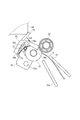
次に、第1実施形態に係る画像形成装置1のシート搬送部3について、図1に加え、図2(a)から図13を参照しながら説明する。まず、シート搬送部3の全体構成について、図2(a)から図3を参照しながら説明する。図2は、(a)は、第1実施形態に係るシート搬送部3の斜視図である。図2(b)は、図2(a)に示すシート搬送部3を反対側から見た斜視図である。図3は、第1実施形態に係るシート搬送部3を模式的に示す断面図である。
Next, the
図2(a)から図3に示すように、シート搬送部3は、シート搬送手段としての複数の搬送ローラ31・・・と、シート搬送手段としての複数の搬送コロ32・・・と、給送フレーム33と、斜行補正部7と、を備えている。複数の搬送ローラ31は、回転軸31aに固着されており、回転軸31aは、シート搬送方向Xと直交するシート幅方向Yと平行に給送フレーム33に回転自在に支持されている。複数の搬送コロ32は、複数の搬送ローラ31と対向するように回転軸32aに回転自在に支持されており、回転軸32aは、複数の搬送コロ32が複数の搬送ローラ31とニップNを形成するように回転軸31aと平行に給送フレーム33に支持されている。なお、シート幅方向Yは、感光体ドラム41a〜41dの回転軸方向に対して平行な方向となっている。
As shown in FIG. 2A to FIG. 3, the
給送フレーム33は、複数の搬送コロ32及び複数の搬送ローラ31により形成されるニップNの上流側に、ガイドフレーム15と共にシートSをニップNに案内する案内部33aを備えている。案内部33aは、ガイドフレーム15と共同して、ニップNの上流側でシートSの厚さ方向における両側を規制してシートSをニップNに案内する。また、案内部33a及びガイドフレーム15は、シートSが後述の係止部材(当接部材)70の当接面70aに当接した後、湾曲してループを形成可能なループ形成部34を構成している。シート搬送部3に搬送されたシートSは、ループ形成部34でループを形成することにより斜行が補正される。なお、本実施形態においては、案内部33aと共にニップNにシートSを案内させるガイドフレーム15を別途設けたが、給送フレーム33に案内部33aと共にシートSをニップNに案内するガイド部を設ける構成であってもよい。
The feeding
斜行補正部7は、給送フレーム33に回動自在に支持された保持部材72と、保持部材72を付勢する第1付勢部としての第1付勢バネ73と、保持部材72に回動自在に保持された複数の係止部材70・・・と、を備えている。また、斜行補正部7は、複数の係止部材70のそれぞれを付勢する第2付勢部としての複数の第2付勢バネ71・・・を備えている。
The
保持部材72は、回転軸31aと平行な回転軸72bを中心に、図3に示す第1位置と、後述の図8に示す第2位置とに回動自在に給送フレーム33に支持されており、第1付勢バネ73により第1位置に位置するように図3に示す矢印Z2方向に付勢されている。つまり、第1付勢バネ73によって保持部材72が矢印Z2方向に回転しようとするのをストッパ89が規制している。また、保持部材72は、複数の係止部材70の回動を規制可能な規制部72aを備えており、規制部72aは、保持部材72の背面側(シート搬送方向の下流側)に設けられている。
The holding
係止部材70は、略L字状に形成されており、シート搬送路上のシートSの下流側先端(以下、単に「先端」という)が当接可能な当接面70aと、規制部72aに突き当て可能な突当面70bと、回転軸72bと平行な回動軸70cと、を備えている。係止部材70は、当接面70aが係止部材70の一端に形成され、突当面70bが他端に形成されている。係止部材70は、当接面70a及び突当面70bが回動軸70cを中心に回動するように保持部材72に相対的に移動自在(回動)に保持されている。保持部材72に設けられた可動支持部72dが回動軸70cを回転自在に支持することで、係止部材70は可動に保持部材72に保持される。保持部材72と係止部材70とは一体的に移動可能(回動可能)である。係止部材70は、保持部材72が第1位置に位置した場合に、当接面70aがニップNの上流側のシート搬送路上に突出状態となる突出位置と、当接面70aが保持部材72側に退避する退避位置(シートが通過可能なシート通過位置)と、に移動可能となっている。突当面70bは、規制部72aに突き当たることで、第2付勢バネ71により突出位置に向かって(図3に示すK1方向)付勢された係止部材70の回動を規制して、係止部材70を突出位置に位置させている。
The locking
次に、第1実施形態に係る斜行補正部7によるシートSの斜行補正について、図3に加え、図4から図13を参照しながら説明する。図4は、シートSが斜行した状態でシート搬送部3に進入する状態を示す平面図である。図5は、突出位置に位置する係止部材70の当接面70aにシートSの先端が当接した状態を示す断面図である。図6は、係止部材70の当接面70aにシートSの先端が突き当たってシートSが湾曲した状態を示す断面図である。図7は、湾曲したシートSにより当接面70aが押されて係止部材70を保持する保持部材72が回動する状態を示す断面図である。図8は、シートSの先端が当接面70aから外れてシートSから受ける反力により係止部材70が回動する状態を示す断面図である。図9は、当接面70aから外れたシートSの表面に接触しながら係止部材70が退避位置に移動する状態を示す図である。図10は、退避位置に退避した係止部材70の上をシートSが通過する状態を示す断面図である。図11は、シートSがニップNを通過する直前の係止部材70を示す断面図である。図12は、シートSがニップNを通過して係止部材70が突出位置に戻った状態を示す断面図である。図13は、シート幅の異なるシートが搬送される状態を示す図である。
Next, skew correction of the sheet S by the
図4に示すように、例えば、シート給送部2から給送されたシートSがシート搬送方向Xに対して斜行した状態でシート搬送部3に進入すると、斜行補正部7が存在しない場合、シートSは、斜行した姿勢のまま下流側の画像形成部4に搬送される。そして、斜行した姿勢のまま画像形成部4に搬送されると、シートSに転写される画像は、シートSに対して傾斜して記録されることになり、記録精度が低下することになる。しかしながら、本実施形態においては、シート搬送部3に斜行補正部7を配設することで、シートSの斜行を補正して搬送可能になるため、記録精度の低下を防止可能となる。以下、斜行補正部7の動作について具体的に説明する。
As shown in FIG. 4, for example, when the sheet S fed from the
まず、図3に示すように、シートSがシート搬送部3に進入する前の状態においては、保持部材72が第1付勢バネ73の付勢力により第1位置に位置している。そして、第1位置に位置する保持部材72に保持された係止部材70が第2付勢バネ71に付勢され、突当面70bが規制部72aに突き当たることで、係止部材70は、突出位置に位置する。これにより、係止部材70の当接面70aがシート搬送路上に位置することになる。以下、保持部材72が第1位置に位置し、係止部材70が突出位置に位置したこの位置を待機位置としての「ホーム位置」という。
First, as shown in FIG. 3, the holding
シートSがシート搬送方向Xに対して斜行した状態でシート搬送部3に進入すると、まず、シートSの先行する側の先端が複数の係止部材70の1つ(例えば、図13に示す係止部材70H)の当接面70aに当接する。この状態においては、第1付勢バネ73の付勢力の方が、シートSを搬送する搬送力(シート給送部2の給送力等)よりも強く設定されているため、保持部材72及び係止部材70は、回動することなくホーム位置に位置したままとなり、シートSが係止される。そして、シート給送部2が更にシートSを給送すると、図5に示すように、シートSの先行する側の先端が当接面70aに係止された状態で、シートSの先端が複数の係止部材70の当接面70aに、順次(図13に示す70G→70F→70E)、当接していく。
When the sheet S enters the
この過程において、シートSは、図6及び図7に示すように、案内部33a及びガイドフレーム15により形成されたループ形成部34で、図6に示す矢印方向に湾曲したループを形成する。なお、このときのシートSの湾曲したループは、図4に示す右側の方が左側より大きくなる。そして、これらの一連の動きにより、シートSの先端が複数の係止部材70の当接面70aにならうことでシート搬送方向Xと直交するシート幅方向Yと平行になり、シートSの斜行が補正される。
In this process, as shown in FIGS. 6 and 7, the sheet S forms a loop curved in the arrow direction shown in FIG. 6 by the
シートSが所定のループを形成すると、第1付勢バネ73の付勢力に抗して保持部材72及び係止部材70を図6に示す矢印Z1方向(回転方向)に移動させる押圧力がシートSのコシの強さにより発生する。これにより、図7に示すように、保持部材72が係止部材70と共にZ1方向に回動し、シートSの先端は、保持部材72の回動途中で搬送ローラ31と搬送コロ32とのニップに挟持される。なお、係止部材70は、当接面70aを押圧するシートSにより保持部材72と共に回動する際、突当面70bが保持部材72の規制部72aに突き当てられていることで突出位置が保持され、突出位置に位置したままの状態で回動される。また、このとき係止部材70は、矢印K2方向(図9参照)には回動しないようになっている。
When the sheet S forms a predetermined loop, the pressing force that moves the holding
ここで、斜行補正部7の斜行補正能力は、案内部33a及びガイドフレーム15により形成されたループ形成部34で、より大きくループをつくる方が高くなる。すなわち、図7に示すように、ループ形成部34は、広く設けることが望ましい。また、所定のループとは、シートSがループ形成部34内でループを形成し、ガイドフレーム15にループの一部が接触することで、シートSのコシが見かけ上強くなり、保持部材72及び係止部材70を回動させることができるループのことである。シートSは、ループ形成部34内でループが形成され、ガイドフレーム15にループの一部が接触することで、シートSのコシが見かけ上強くなり、保持部材72及び係止部材70を回動させることができるようになる。
Here, the skew correction ability of the
図8に示すように、シートSの先端に押された保持部材72が係止部材70と共に更に回動して、保持部材72が第2位置に到達すると、保持部材72に保持された係止部材70の当接面70aがシート搬送路から退避することになる。係止部材70の当接面70aがシート搬送路から退避すると、シートSの先端が当接面70aの頂点を越える。つまり、シートSの先端が当接面70aから外れる。シートSの先端が当接面70aから外れると、係止部材70が、搬送ローラ31と搬送コロ32とのニップNに挟持されたシートSから図8に示す矢印M方向(退避位置方向)の反力を受ける。係止部材70がシートSから矢印M方向の反力を受けると、係止部材70は、図9に示すように、第2付勢バネ71の付勢力に抗して矢印K2方向に回動を開始し、退避位置に向かって移動を開始する。なお、第2付勢バネ71は、シートSの反力によるモーメントよりも弱い力で係止部材70をK1方向に付勢するように設定されており、係止部材70は、シートSの反力を受けるとK2方向に回動するようになっている。
As shown in FIG. 8, when the holding
また、保持部材72は、シートSからの押圧力がなくなるため、第1付勢バネ73の付勢力により、第1位置に向かって図9に示す矢印Z2方向に回動を開始する。保持部材72が矢印Z2方向に移動することで、係止部材70は、シートSの表面に接触しながら更に退避位置に向かって移動する。そして、図10に示すように、保持部材72が第1位置に戻ると、係止部材70は、シート搬送路を通過中のシートSにより突出位置への移動(表面側への移動)が規制されることで、シートSの表面に接触して退避位置で待機する状態となる。保持部材72が第1位置に位置した図10において、シートの表面と接している係止部材70の当接面70aは、レジストレーションローラ対11のニップよりも上流に位置する。そして、シートSがシート給送部2を抜けると、シートSのコシが弱くなっていき、図11に示すように、係止部材70は、突出位置(ホーム位置)に徐々に戻っていく。更に、シートSの後端がシート搬送路を通過する(搬送ローラ31と搬送コロ32とのニップNを抜ける)と、図12に示すように、係止部材70が第2付勢バネ71の付勢力で突出位置に戻り、当接面70aがシート搬送路上に位置するようになる。つまり、後続のシートの斜行を補正するためのホーム位置で待機する状態となる。このように、図5から図12に示した上述の動作を繰り返すことで、シート給送部2から順次給送されるシートSの斜行を順次補正することができる。
Further, since the pressing force from the sheet S is lost, the holding
以上説明したように、第1実施形態に係る画像形成装置1は、係止部材70の当接面70aにシートSを当接させてシートSの斜行を補正した後、保持部材72が係止部材70と共に第2位置に移動する。そして、第2位置でシートSの先端が当接面70aから外れると、保持部材72が第1位置に戻って、係止部材70が退避位置でシートSが通過するまで待機する。そのため、シートSが通過すると直ちに、係止部材70を次のシートSの先端を当接面70aに当接可能な突出位置に戻し、斜行補正部7をホーム位置に戻すことができる。これにより、シートSが通過してから係止部材70がホーム位置に位置するまでの時間を短くすることができる。その結果、シート搬送速度を速くした場合においても、紙間距離が長くなることを抑止し、スループットを向上させることができる。
As described above, in the
また、シートSの幅が比較的大きい場合(図13の実線で示すシートS)、主としてシートSの両側端部近傍に対応して配置される2つの係止部材70E、70HがシートSの先端に作用してシートSの斜行が補正される。一方、使用されるシートSの幅が、係止部材70E、70Hにかからないような比較的小さい場合(図13の点線で示すシートS)、係止部材70E、70Hよりも中央部に配置された係止部材70F、70GによってシートSの斜行が補正される。画像形成装置1は、係止部材70F、70Gを設けることで、シート先端が当接する係止部材の当接面での接触圧を和らげることができ、シートSの幅が比較的大きい場合のシート先端を係止部材に接触した跡が局部的に発生することを防止することができる。
When the width of the sheet S is relatively large (the sheet S indicated by the solid line in FIG. 13), the two locking
また、より精度の良いシートSの斜行補正能力を得るためには、シートSの幅に対応する複数の係止部材70の間隔ができるだけ広く、かつシートSの幅の中央に略対称に配置した方がよい。これは、搬送ローラ31及び搬送コロ32の回転軸方向に対するシートSの先端の補正角度誤差を小さくするためである。そのため、搬送されるシートSの両端部近傍に係止部材70を配置するが、比較的小さな幅のシートSでも斜行補正できるようにシートSの搬送中央部c近傍にも係止部材70を配置して構成することが好ましい。
Further, in order to obtain a more accurate skew correction capability of the sheet S, the intervals between the plurality of locking
更に、この時、シートSのシート搬送路の搬送中央部Cに近い両側の二つの係止部材70F、70Gの間隔を、シートSの最小の幅よりも小さくすることが好ましい。その場合、係止部材70F、70Gのシート先端に当接する当接面70aは、係止部材70E、70Hよりもシート搬送方向のわずかに下流側に配置することが好ましい。これにより、幅の大きいシートSを補正するときに、係止部材70F,70GがシートSの先端に接触しないため、補正角度誤差を小さくすることができる。
Further, at this time, it is preferable that the interval between the two locking
また、当接面70aと、搬送ローラ31及び搬送コロ32のニップNとの間の距離を小さくすることにより、係止部材70によりシートSの斜行補正が行われた直後に搬送ローラ31及び搬送コロ32のニップNに挟持されて搬送される。そのため、シートSの斜行補正効果を維持することができる。また、係止部材70のシートSの先端に当接する当接面70aをシート搬送方向Xと直交するシート幅方向Yにおいて、シート幅の中央に対し、略対称に複数設けることで、より精度良いシートSの斜行補正能力を得ることができる。また、シートSが係止部材70に接触した跡を局部的に形成することを防ぐこともできる。
Further, by reducing the distance between the
なお、図14に示すように、シート搬送部3の複数の係止部材70は、例えば、それぞれが背面側で、連結部75により連結されている構成であってもよい。
As shown in FIG. 14, the plurality of locking
<第2実施形態>
次に、本発明の第2実施形態に係る画像形成装置1Aについて、図1を援用すると共に、図15から図18を参照しながら説明する。第2実施形態に係る画像形成装置1Aは、保持部材72が第2位置に回動した際に、係止部材70を押圧部材としての押圧部16に押し当てて移動させることにおいて、第1実施形態と相違する。そのため、第2実施形態においては、第1実施形態と相違する点、すなわち、係止部材70を回動させる構成を中心に説明し、第1実施形態に係る画像形成装置1と同様の構成のものについては、同じ符号を付してその説明を省略する。
Second Embodiment
Next, an
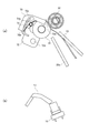
まず、第2実施形態に係る画像形成装置1Aの全体構造について、図1を援用すると共に、図15を参照しながら説明する。図15は、第2実施形態に係るシート搬送部3Aを示す斜視図である。
First, the overall structure of the
図1に示すように、第2実施形態に係る画像形成装置1Aは、シート給送部2と、シート搬送部3Aと、画像形成部4と、定着部5と、排出部6と、画像形成装置本体に形成された押圧部16と、を備えている。図15に示すように、シート搬送部3Aは、複数の搬送ローラ31・・・と、複数の搬送コロ32・・・と、給送フレーム33と、斜行補正部7Aと、を備えている。斜行補正部7Aは、保持部材72と、第1付勢バネ73と、複数の係止部材70・・・と、複数の第2付勢バネ71・・・と、押圧部16に当接可能に形成された被押圧部74と、連結部75と、を備えている。連結部75は、複数の係止部材70の背面側で複数の係止部材70を連結しており、被押圧部74は、連結部75に連結されている。
As shown in FIG. 1, an
次に、第2実施形態に係る画像形成装置1Aのシート搬送部3Aの斜行補正部7AによるシートSの斜行補正について、図16から図18を参照しながら説明する。図16は、係止部材70の当接面70aにシートSの先端が突き当たってシートSが湾曲した状態を示す断面図である。図17は、湾曲したシートSより当接面70aが押されて係止部材70を保持する保持部材72が回動し、押圧部16に被押圧部74が当接した状態を示す断面図である。図18は、シートSの先端が当接面70aから外れて押圧部16から受ける押圧力により係止部材70が回動する状態を示す図である。
Next, skew correction of the sheet S by the
図16に示すように、保持部材72及び係止部材70がホーム位置にあるときには、被押圧部74は、押圧部16と接触しない位置にある。この状態で、シートSがシート搬送部3Aに進入して、シートSの先端が係止部材70の当接面70aに当接すると、シートSが湾曲してループを形成し、保持部材72がシートSに押圧されて係止部材70と共に第2位置に回動する。
As shown in FIG. 16, when the holding
図17に示すように、突出位置にある係止部材70を保持する保持部材72が第2位置に回動すると、被押圧部74が押圧部16と接触して、突出位置にある係止部材70が退避位置に押圧される。このとき、保持部材72が第2位置に到達することで、保持部材72に保持された係止部材70の当接面70aがシート搬送路から退避し、シートSの先端が当接面70aから外れる。そのため、係止部材70が退避位置に向かって押圧されると、図18に示すように、シートSの搬送を阻害することなく、係止部材70は、移動可能となる。また、このとき、シートSの先端が当接面70aに当接したままの場合においても、係止部材70を退避位置に向かって回動させることで、例えば、シートSのコシの強さ等により当接面70aから外すこともできる。
As shown in FIG. 17, when the holding
以上説明したように、第2実施形態に係る画像形成装置1Aは、押圧部16及び被押圧部74を設けることで、係止部材70が保持部材72と共に第2位置に移動した際に、係止部材70を確実に退避位置に向かって回動させることができる。
As described above, the
<第3実施形態>
次に、本発明の第3実施形態に係る画像形成装置1Bについて、図1を援用すると共に、図19から図22を参照しながら説明する。第3実施形態に係る画像形成装置1Bは、斜行補正部7にシートSの先端を検知可能な先端検知部を設けた点において、第1実施形態と相違する。そのため、第3実施形態においては、第1実施形態と相違する点、即ち、先端検知部を中心に説明し、第1実施形態に係る画像形成装置1と同様の構成のものについては、同じ符号を付してその説明を省略する。
<Third Embodiment>
Next, an
まず、第3実施形態に係る画像形成装置1Bの全体構造について、図1を援用すると共に、図19を参照しながら説明する。図19は、第3実施形態に係るシート搬送部3Bを示す斜視図である。
First, the overall structure of an
図1に示すように、第3実施形態に係る画像形成装置1Bは、シート給送部2と、シート搬送部3Bと、画像形成部4と、定着部5と、排出部6と、を備えている。図19に示すように、シート搬送部3Bは、複数の搬送ローラ31・・・と、複数の搬送コロ32・・・と、給送フレーム33と、斜行補正部7Bと、を備えている。斜行補正部7Bは、保持部材72と、第1付勢バネ73と、複数の係止部材70・・・と、複数の第2付勢バネ71・・・と、シート検知部材としての検知レバー17と、検知センサ18と、を備えている。先端検知部は、検知レバー17及び検知センサ18により構成されている。
As shown in FIG. 1, the
検知レバー17は、係止部材70の回動軸70cと同軸上に接続されており、係止部材70の移動と連動して移動するように構成されている。検知センサ18は、発光素子及び受光素子による光路を形成した光学センサ(例えば、フォトセンサ)であり、給送フレーム33に取り付けられている。検知センサ18は、保持部材72及び係止部材70がホーム位置に位置することで検知レバー17に光路を遮光され、検知レバー17による光路の遮光が解除されると検知信号を発信するように構成されている。つまり、保持部材72が係止部材70と共に第2位置に移動することでシートSの先端が検知され、シートSの先端が検知されると検知センサ18が検知信号を発信するようになっている。
The
次に、第3実施形態に係る画像形成装置1Bのシート搬送部3Bの斜行補正部7BによるシートSの斜行補正について、図20から図22を参照しながら説明する。図20は、第3実施形態に係るシート搬送部3BにシートSが進入する状態を示す図である。図21は、保持部材72が第2位置に移動してシートSの先端が当接面70aから外れた状態を示す図である。図22は、退避位置に退避した係止部材70の上をシートSが通過する状態を示す断面図である。なお、図20から図22における符号(a)は、保持部材72等の状態を示す図であり、符号(b)は、先端検知部の状態を示す図である。
Next, skew correction of the sheet S by the
図20(a)に示すように、保持部材72及び係止部材70がホーム位置にあるときには、図20(b)に示すように、検知レバー17が検知センサ18の光路を遮光した遮光状態にある。次に、図21(a)に示すように、保持部材72が係止部材70と共に第2位置に移動すると、図21(b)に示すように、検知レバー17が係止部材70に連動することで、検知センサ18の光路から離間する。これにより、検知レバー17による検知センサの光路の遮光が解除され、遮光が解除されると、シートSが所望の位置に到達したと検知し、検知センサ18が検知信号を発信する。
As shown in FIG. 20A, when the holding
検知センサ18が発信した検知信号を受信すると、画像形成部4が搬送されるシートSに転写する画像の画像形成動作を開始する。その後、第1実施形態と同様の動作を行い、図22(a)に示すように、保持部材72が第1位置に位置した状態で係止部材70は退避位置に位置してシートの通過するまで待機する。図22(b)に示すように、その間も、検知レバー17は、検知センサ18の光路から離間している。そして、シートSの通過に伴って、係止部材70が突出位置に戻ることで、検知レバー17が検知センサ18の光路の遮光し、検知センサ18が検知信号の発信を停止する。
When the detection signal transmitted from the
以上説明したように、第3実施形態に係る画像形成装置1Bは、係止部材70に連動する検知レバー17と、検知センサ18とを設けることで、係止部材70及び保持部材72によるシートSの斜行補正に加え、シートSの先端位置の検知を行うことができる。これにより、シート搬送部3Bで斜行が補正されたシートSの先端を検知することで、画像形成部4による画像形成のタイミングをシートSの位置に連動させることができる。その結果、例えば、シートSの先端位置を検出するシート検知部を別途設ける必要がなくなり、製造コスト等を抑制させることができる。
As described above, the
また、検知レバー17は、係止部材70と同様の動作を行うので、シートSの後端がシート搬送路を通過するのとほぼ同時に、次のシートSの先端を検知するためのホーム位置(検知センサ18を遮光する位置)で待機することができる。これにより、シート搬送速度の速い条件のもと、短い紙間の中でも、次のシートSの先端を検知するためのホーム位置に戻ることが可能となり、ユーザからのさらなる画像形成装置のスループット向上の要求に応えることができる。
Further, since the
以上、本発明の実施形態について説明したが、本発明は上述した実施形態に限定されるものではない。また、本発明の実施形態に記載された効果は、本発明から生じる最も好適な効果を列挙したに過ぎず、本発明による効果は、本発明の実施形態に記載されたものに限定されない。 As mentioned above, although embodiment of this invention was described, this invention is not limited to embodiment mentioned above. In addition, the effects described in the embodiments of the present invention only list the most preferable effects resulting from the present invention, and the effects of the present invention are not limited to those described in the embodiments of the present invention.
例えば、本実施形態においては、係止部材70は、突出位置と退避位置とに回動自在に保持部材72に保持させたが、本発明においてはこれに限定されない。例えば、係止部材は、保持部材に突出位置と退避位置とに出没自在(スライド移動自在)に支持されてもよい。
For example, in this embodiment, the locking
また、本実施形態においては、第1付勢手段及び第2付勢手段として、付勢バネを用いて説明したが、本発明においてはこれに限定されない。例えば、弾性体等で付勢する構成であってもよい。また、本実施形態においては、シート搬送手段として、搬送ローラ31及び搬送コロ32を用いて説明したが、本発明においてはこれに限定されない。シート搬送手段は、シートSを挟持して搬送可能なものであればよい。
In the present embodiment, the first urging means and the second urging means are described using urging springs, but the present invention is not limited to this. For example, the structure biased with an elastic body etc. may be sufficient. In the present embodiment, the sheet conveying unit is described using the conveying
1、1A、1B 画像形成装置
3、3A、3B シート搬送部(シート搬送装置)
4 画像形成部
7、7A、7B 斜行補正部
16 押圧部(押圧部材)
17 検知レバー
18 検知センサ
31 搬送ローラ(シート搬送手段)
32 搬送コロ(シート搬送手段)
70 係止部材
70a 当接面
71 第2付勢バネ(第2付勢部)
72 保持部材
72d 可動支持部
73 第1付勢バネ(第1付勢部)
74 被押圧部
S シート
1, 1A, 1B
4
17 Detecting
32 Conveyance roller (sheet conveyance means)
70
72 holding
74 Pressed part S sheet
Claims (20)
第1位置決め部を備え前記当接部材を保持する保持部材と、を有し、
前記当接部材は、前記第1位置決め部に接触した状態で前記保持部材に対して位置決めされ前記当接面が前記シートの先端と当接する当接位置と、前記保持部材に対する位置決めが解消され前記当接面が前記シートの先端と当接しない退避位置と、に移動可能であり、
前記保持部材は、位置決めされた第1位置と、前記第1位置から退避した第2位置と、に移動可能であり、
前記当接部材が前記当接位置に位置し且つ前記保持部材が前記第1位置に位置する待機状態で前記当接面が前記シートの先端に押され、前記当接部材が前記第1位置決め部に接触した状態で、前記保持部材は前記第1位置から前記第2位置の方向へ移動し、
前記保持部材が前記第1位置から離れる方向に移動することで前記シートの先端が前記当接面から外れ、前記シートの面に押されることで前記当接部材が前記退避位置に移動した状態で、前記保持部材は前記第2位置から前記第1位置へ移動する、
ことを特徴とするシート搬送装置。 A contact member having a contact surface that comes into contact with the leading edge of the sheet for correcting skew feeding of the conveyed sheet;
A holding member that includes the first positioning portion and holds the contact member;
The contact member is positioned with respect to the holding member in contact with the first positioning portion, the contact position where the contact surface contacts the leading edge of the sheet, and the positioning with respect to the holding member is canceled. The abutting surface is movable to a retracted position where it does not abut against the leading edge of the sheet,
The holding member is movable between a first position that is positioned and a second position that is retracted from the first position;
In a standby state where the contact member is located at the contact position and the holding member is located at the first position, the contact surface is pressed against the leading edge of the sheet, and the contact member is moved to the first positioning portion. The holding member moves in the direction from the first position to the second position,
When the holding member moves in a direction away from the first position, the leading edge of the sheet is detached from the contact surface, and the contact member is moved to the retracted position by being pushed by the surface of the sheet. The holding member moves from the second position to the first position;
A sheet conveying apparatus.
前記保持部材が前記第1位置から前記第2位置に移動する場合、前記保持部材は前記第1付勢手段の付勢力に抗して移動する、
ことを特徴とする請求項1に記載のシート搬送装置。 Have a first biasing means for biasing said holding member,
When the holding member moves from the first position to the second position, the holding member moves against the urging force of the first urging means ;
The sheet conveying apparatus according to claim 1.
ことを特徴とする請求項1又は請求項2に記載のシート搬送装置。 A second urging means for urging the contact member from the retracted position toward the contact position ;
The sheet conveying apparatus according to claim 1 or 2,
ことを特徴とする請求項1乃至請求項3のいずれか1項に記載のシート搬送装置。 The contact member is rotatable with respect to the holding member about a first rotation axis.
The sheet conveying apparatus according to any one of claims 1 to 3, wherein the sheet conveying apparatus is characterized in that:
ことを特徴とする請求項4に記載のシート搬送装置。 The holding member is rotatable around a second rotation axis different from the first rotation axis.
The sheet conveying apparatus according to claim 4.
前記保持部材が前記第1位置に位置する場合、前記当接部材の前記当接面はシート搬送方向に関して前記挟持部の上流側に位置する、
ことを特徴とする請求項1乃至請求項5のいずれか1項に記載のシート搬送装置。 Forming a sandwiching section and having a conveying means for sandwiching and conveying the sheet;
When the holding member is located at the first position, the abutting surface of the abutting member is located on the upstream side of the clamping unit with respect to the sheet conveying direction.
The sheet conveying apparatus according to claim 1, wherein the sheet conveying apparatus is a sheet conveying apparatus.
ことを特徴とする請求項1乃至請求項6のいずれか1項に記載のシート搬送装置。 A plurality of the contact members are provided in the width direction intersecting the sheet conveying direction.
The sheet conveying device according to any one of claims 1 to 6 , wherein the sheet conveying device is characterized in that:
ことを特徴とする請求項1乃至請求項7のいずれか1項に記載のシート搬送装置。 A stopper for positioning the holding member at the first position;
The sheet conveying device according to any one of claims 1 to 7 , wherein the sheet conveying device is characterized in that:
前記シート搬送装置により斜行が補正された状態で搬送されるシートに画像を形成する画像形成部と、を備えた、
ことを特徴とする画像形成装置。 A sheet conveying device according to any one of claims 1 to 8 ,
An image forming unit that forms an image on a sheet that is conveyed in a state in which skew feeding is corrected by the sheet conveying device,
An image forming apparatus.
前記当接面が前記シートの先端と当接する当接位置と、前記当接面が前記シートの先端と当接しない退避位置と、に移動可能に前記当接部材を保持し、待機位置に位置する状態で前記当接部材の前記当接面が前記シートの先端に押されることにより、前記当接部材と共に前記待機位置から所定方向に移動する保持部材と、
前記保持部材の前記所定方向への移動によって前記シートの先端が前記当接面から外れ前記当接部材が前記シートの面に接触した状態で前記シートを搬送する搬送手段と、
前記搬送手段により搬送される前記シートの面に前記当接部材が接触した状態で、前記保持部材を前記待機位置に移動させるように、前記保持部材を付勢する第1付勢手段と、
前記保持部材が前記待機位置に位置する状態で、前記搬送手段により搬送される前記シートの面との接触が解消された前記当接部材を前記退避位置から前記当接位置に移動させるように、前記当接部材を付勢する第2付勢手段と、を有する、
ことを特徴とするシート搬送装置。 A contact member having a contact surface that contacts the leading edge of the conveyed sheet;
The abutting member is movably held between the abutting position where the abutting surface abuts against the leading edge of the sheet and the retracted position where the abutting surface does not abut against the leading edge of the sheet, and is positioned at the standby position. A holding member that moves in a predetermined direction from the standby position together with the contact member by pressing the contact surface of the contact member against the leading edge of the sheet in a state of
Conveying means for conveying the sheet in a state where the leading edge of the sheet is detached from the contact surface by the movement of the holding member in the predetermined direction and the contact member is in contact with the surface of the sheet;
First urging means for urging the holding member so as to move the holding member to the standby position in a state where the contact member is in contact with the surface of the sheet conveyed by the conveying means;
In a state where the holding member is located at the standby position, the contact member that has been released from contact with the surface of the sheet conveyed by the conveyance unit is moved from the retracted position to the contact position. Second urging means for urging the abutting member;
A sheet conveying apparatus.
ことを特徴とする請求項10に記載のシート搬送装置。 The first biasing means biases the holding member so as to move the holding member in a direction opposite to the predetermined direction;
Sheet conveying device according to claim 1 0, characterized in that.
ことを特徴とする請求項11に記載のシート搬送装置。 A stopper for positioning the holding member biased to move in the reverse direction by the first biasing means;
Sheet conveying device according to claim 1 1, wherein the.
ことを特徴とする請求項10乃至請求項12のいずれか1項に記載のシート搬送装置。 The abutting surface of the abutting member can correct the skew of the sheet by abutting on the leading end of the conveyed sheet.
Sheet conveying device according to any one of claims 1 0 to claim 1 2, characterized in that.
ことを特徴とする請求項10乃至請求項13のいずれか1項に記載のシート搬送装置。 The contact member is rotatable with respect to the holding member about a first rotation axis.
Sheet conveying device according to any one of claims 1 0 to claim 1 3, characterized in that.
ことを特徴とする請求項14に記載のシート搬送装置。 The holding member is rotatable around a second rotation axis different from the first rotation axis.
Sheet conveying device according to claim 1 4, characterized in that.
前記保持部材及び前記当接部材は、前記第2ローラ側に設けられている、
ことを特徴とする請求項10乃至請求項15のいずれか1項に記載のシート搬送装置。 The conveying means is a roller pair including a first roller and a second roller,
The holding member and the contact member are provided on the second roller side,
Sheet conveying device according to any one of claims 1 0 to claims 1 to 5, characterized in that.
ことを特徴とする請求項10乃至請求項16のいずれか1項に記載のシート搬送装置。 A plurality of the contact members are provided in the width direction intersecting the sheet conveying direction.
Sheet conveying device according to any one of claims 1 0 to claim 1 6, characterized in that.
ことを特徴とする請求項10乃至請求項17のいずれか1項に記載のシート搬送装置。 The holding member includes a positioning portion for positioning the contact member biased by the second biasing unit with respect to the holding member.
It sheet conveying device according to any one of claims 1 0 to claim 17, wherein.
前記シート搬送装置により斜行が補正された状態で搬送されるシートに画像を形成する画像形成部と、を備えた、
ことを特徴とする画像形成装置。 A sheet conveying device according to any one of claims 1 0 to claim 18,
An image forming unit that forms an image on a sheet that is conveyed in a state in which skew feeding is corrected by the sheet conveying device,
An image forming apparatus.
第1位置と前記第1位置とは異なる第2位置との間で移動可能な保持部材と、前記保持部材に対して当接位置と退避位置との間で相対的に移動可能に支持され、前記搬送手段によって搬送される前記シートの先端に当接して前記シートの斜行を補正可能な当接面を有する当接部材と、前記保持部材を前記第2位置から前記第1位置に向けて付勢する第1付勢手段と、前記当接部材を前記退避位置から前記当接位置に向けて付勢する第2付勢手段と、を有する斜行補正手段と、を備え、
前記斜行補正手段は、前記保持部材が前記第1位置に位置しかつ前記当接部材が前記当接位置に位置して、前記当接面に前記シートの先端が当接可能な第1状態と、前記保持部材が前記第2位置に位置しかつ前記当接部材が前記当接位置に位置して、前記シートの先端が前記当接面から離間する第2状態と、前記保持部材が前記第1位置に位置しかつ前記当接部材が前記退避位置に位置して、前記当接部材の前記当接面とは異なる面が前記シートの面に当接する第3状態と、を取り得る、
ことを特徴とするシート搬送装置。 Conveying means for conveying the sheet in the sheet conveying direction;
A holding member movable between a first position and a second position different from the first position, and supported relative to the holding member so as to be relatively movable between a contact position and a retracted position; An abutting member having an abutting surface that abuts on the leading edge of the sheet conveyed by the conveying means and can correct the skew of the sheet, and the holding member from the second position toward the first position. Skew correction means having first biasing means for biasing, and second biasing means for biasing the contact member from the retracted position toward the contact position,
The skew feeding correcting means is a first state in which the holding member is located at the first position and the abutting member is located at the abutting position so that the leading edge of the sheet can abut on the abutting surface. A second state in which the holding member is located at the second position and the contact member is located at the contact position, and the leading edge of the sheet is separated from the contact surface; and A third state in which the contact member is located at the first position and the contact member is located at the retracted position, and a surface different from the contact surface of the contact member contacts the surface of the sheet;
A sheet conveying apparatus.
Priority Applications (1)
| Application Number | Priority Date | Filing Date | Title |
|---|---|---|---|
| JP2013019235A JP6128870B2 (en) | 2012-02-08 | 2013-02-04 | Sheet conveying apparatus and image forming apparatus |
Applications Claiming Priority (3)
| Application Number | Priority Date | Filing Date | Title |
|---|---|---|---|
| JP2012025190 | 2012-02-08 | ||
| JP2012025190 | 2012-02-08 | ||
| JP2013019235A JP6128870B2 (en) | 2012-02-08 | 2013-02-04 | Sheet conveying apparatus and image forming apparatus |
Related Child Applications (1)
| Application Number | Title | Priority Date | Filing Date |
|---|---|---|---|
| JP2017078671A Division JP6320598B2 (en) | 2012-02-08 | 2017-04-12 | Sheet conveying apparatus and image forming apparatus |
Publications (3)
| Publication Number | Publication Date |
|---|---|
| JP2013177244A JP2013177244A (en) | 2013-09-09 |
| JP2013177244A5 JP2013177244A5 (en) | 2016-08-18 |
| JP6128870B2 true JP6128870B2 (en) | 2017-05-17 |
Family
ID=47790420
Family Applications (3)
| Application Number | Title | Priority Date | Filing Date |
|---|---|---|---|
| JP2013019235A Active JP6128870B2 (en) | 2012-02-08 | 2013-02-04 | Sheet conveying apparatus and image forming apparatus |
| JP2017078671A Active JP6320598B2 (en) | 2012-02-08 | 2017-04-12 | Sheet conveying apparatus and image forming apparatus |
| JP2018072725A Active JP6513255B2 (en) | 2012-02-08 | 2018-04-04 | Sheet conveying apparatus and image forming apparatus |
Family Applications After (2)
| Application Number | Title | Priority Date | Filing Date |
|---|---|---|---|
| JP2017078671A Active JP6320598B2 (en) | 2012-02-08 | 2017-04-12 | Sheet conveying apparatus and image forming apparatus |
| JP2018072725A Active JP6513255B2 (en) | 2012-02-08 | 2018-04-04 | Sheet conveying apparatus and image forming apparatus |
Country Status (3)
| Country | Link |
|---|---|
| US (4) | US9388005B2 (en) |
| JP (3) | JP6128870B2 (en) |
| WO (1) | WO2013118789A1 (en) |
Families Citing this family (5)
| Publication number | Priority date | Publication date | Assignee | Title |
|---|---|---|---|---|
| WO2013118790A1 (en) * | 2012-02-08 | 2013-08-15 | Canon Kabushiki Kaisha | Sheet detecting apparatus, sheet conveying apparatus, and image forming apparatus |
| JP6456024B2 (en) * | 2014-01-31 | 2019-01-23 | キヤノン株式会社 | Roller, cartridge, image forming apparatus, and cylindrical shaft manufacturing method |
| CN105984738B (en) * | 2015-02-03 | 2018-02-27 | 柯尼卡美能达办公系统研发(无锡)有限公司 | Image processing system and its paper delivering mechanism |
| JP6700722B2 (en) | 2015-11-04 | 2020-05-27 | キヤノン株式会社 | Sheet detecting device, sheet conveying device, and image forming device |
| JP7313837B2 (en) * | 2019-02-08 | 2023-07-25 | キヤノン株式会社 | Sheet conveying device and image forming device |
Family Cites Families (23)
| Publication number | Priority date | Publication date | Assignee | Title |
|---|---|---|---|---|
| JPS61248829A (en) * | 1985-04-26 | 1986-11-06 | Mita Ind Co Ltd | Automatic paper feeder with positioning stopper |
| JPH0383539A (en) | 1989-08-28 | 1991-04-09 | Fuji Oil Co Ltd | Production of whipped cream |
| US5042790A (en) * | 1990-02-16 | 1991-08-27 | Xerox Corporation | Toggled switch for use in a sheet feed apparatus |
| JPH08119498A (en) * | 1994-10-20 | 1996-05-14 | Fuji Xerox Co Ltd | Sheet registering device for image forming device |
| JP3473648B2 (en) * | 1995-03-22 | 2003-12-08 | セイコーエプソン株式会社 | Printer paper detector |
| JP3768578B2 (en) | 1996-01-08 | 2006-04-19 | キヤノン株式会社 | Sheet skew correcting device, sheet conveying device, and image forming apparatus |
| US6394447B1 (en) * | 1999-09-17 | 2002-05-28 | Omron Corporation | Sheet inversion device |
| KR100431005B1 (en) * | 2002-05-14 | 2004-05-12 | 삼성전자주식회사 | apparatus for sensing paper for use in an office machine |
| KR100788656B1 (en) * | 2004-02-26 | 2007-12-26 | 삼성전자주식회사 | Apparatus for arranging paper and electrophotographic image forming apparatus therewith |
| KR100739766B1 (en) * | 2005-12-02 | 2007-07-13 | 삼성전자주식회사 | Registration unit and Image forming apparatus adopting the same |
| KR100739780B1 (en) * | 2005-12-26 | 2007-07-13 | 삼성전자주식회사 | Image forming apparatus including shutter arm unit |
| US7823879B2 (en) * | 2007-02-08 | 2010-11-02 | Lexmark International, Inc. | Apparatus for deskewing sheet media |
| CN101412478B (en) * | 2007-10-19 | 2011-05-18 | 旭丽电子(广州)有限公司 | Medium deflexion correction mechanism |
| WO2011048669A1 (en) * | 2009-10-20 | 2011-04-28 | キヤノン株式会社 | Sheet detecting device and image forming device |
| KR101350124B1 (en) * | 2009-10-20 | 2014-01-09 | 캐논 가부시끼가이샤 | Sheet conveying device and image forming apparatus |
| JP5696565B2 (en) | 2010-06-28 | 2015-04-08 | 株式会社リコー | Sheet conveying apparatus and image forming apparatus |
| JP5591057B2 (en) * | 2010-10-13 | 2014-09-17 | キヤノン株式会社 | Sheet conveying apparatus and image forming apparatus |
| JP5713690B2 (en) * | 2011-01-13 | 2015-05-07 | キヤノン株式会社 | Sheet conveying apparatus and image forming apparatus |
| WO2013118790A1 (en) | 2012-02-08 | 2013-08-15 | Canon Kabushiki Kaisha | Sheet detecting apparatus, sheet conveying apparatus, and image forming apparatus |
| JP5740341B2 (en) * | 2012-04-06 | 2015-06-24 | 京セラドキュメントソリューションズ株式会社 | Sheet detecting apparatus, automatic document feeder, and image forming apparatus |
| JP6049445B2 (en) * | 2012-12-26 | 2016-12-21 | キヤノン株式会社 | Sheet conveying apparatus and image forming apparatus |
| CN204084030U (en) * | 2014-09-11 | 2015-01-07 | 深圳Tcl新技术有限公司 | Led module and display |
| JP6700722B2 (en) * | 2015-11-04 | 2020-05-27 | キヤノン株式会社 | Sheet detecting device, sheet conveying device, and image forming device |
-
2013
- 2013-01-31 US US14/365,746 patent/US9388005B2/en active Active
- 2013-01-31 WO PCT/JP2013/052779 patent/WO2013118789A1/en active Application Filing
- 2013-02-04 JP JP2013019235A patent/JP6128870B2/en active Active
-
2016
- 2016-05-13 US US15/153,904 patent/US9586778B2/en active Active
-
2017
- 2017-01-19 US US15/409,681 patent/US9938102B2/en active Active
- 2017-04-12 JP JP2017078671A patent/JP6320598B2/en active Active
-
2018
- 2018-02-28 US US15/907,704 patent/US10759618B2/en active Active
- 2018-04-04 JP JP2018072725A patent/JP6513255B2/en active Active
Also Published As
| Publication number | Publication date |
|---|---|
| US20160251185A1 (en) | 2016-09-01 |
| JP6320598B2 (en) | 2018-05-09 |
| US9586778B2 (en) | 2017-03-07 |
| JP2018104202A (en) | 2018-07-05 |
| US9388005B2 (en) | 2016-07-12 |
| US20180186588A1 (en) | 2018-07-05 |
| JP2013177244A (en) | 2013-09-09 |
| US10759618B2 (en) | 2020-09-01 |
| JP2017122009A (en) | 2017-07-13 |
| WO2013118789A1 (en) | 2013-08-15 |
| JP6513255B2 (en) | 2019-05-15 |
| US20170129727A1 (en) | 2017-05-11 |
| US20140361483A1 (en) | 2014-12-11 |
| US9938102B2 (en) | 2018-04-10 |
Similar Documents
| Publication | Publication Date | Title |
|---|---|---|
| JP6320598B2 (en) | Sheet conveying apparatus and image forming apparatus | |
| JP5591057B2 (en) | Sheet conveying apparatus and image forming apparatus | |
| JP5804735B2 (en) | Sheet conveying apparatus and image forming apparatus | |
| JP6188340B2 (en) | Sheet detecting apparatus and image forming apparatus | |
| US11231672B2 (en) | Image forming apparatus | |
| JP5713690B2 (en) | Sheet conveying apparatus and image forming apparatus | |
| JP6723700B2 (en) | Sheet conveying apparatus and image forming apparatus | |
| US9815650B2 (en) | Sheet skew feed correction apparatus, image forming apparatus and skew feed correction apparatus | |
| US8876108B2 (en) | Sheet transport apparatus and image forming apparatus | |
| JP6615288B2 (en) | Image forming apparatus | |
| JP2013154979A (en) | Skewed sheet correcting device and image forming apparatus | |
| JP5025316B2 (en) | Image forming apparatus | |
| JP2009149391A (en) | Sheet conveying device and image forming apparatus | |
| JP6833369B2 (en) | Sheet transfer device and image forming device | |
| JP6400063B2 (en) | Sheet conveying apparatus and image forming apparatus | |
| JP6391351B2 (en) | Sheet detecting apparatus and image forming apparatus | |
| JP5897181B2 (en) | Sheet conveying apparatus and image forming apparatus |
Legal Events
| Date | Code | Title | Description |
|---|---|---|---|
| A621 | Written request for application examination |
Free format text: JAPANESE INTERMEDIATE CODE: A621 Effective date: 20160203 |
|
| A521 | Request for written amendment filed |
Free format text: JAPANESE INTERMEDIATE CODE: A523 Effective date: 20160630 |
|
| A871 | Explanation of circumstances concerning accelerated examination |
Free format text: JAPANESE INTERMEDIATE CODE: A871 Effective date: 20160630 |
|
| A975 | Report on accelerated examination |
Free format text: JAPANESE INTERMEDIATE CODE: A971005 Effective date: 20160727 |
|
| A131 | Notification of reasons for refusal |
Free format text: JAPANESE INTERMEDIATE CODE: A131 Effective date: 20160809 |
|
| A521 | Request for written amendment filed |
Free format text: JAPANESE INTERMEDIATE CODE: A523 Effective date: 20161011 |
|
| A131 | Notification of reasons for refusal |
Free format text: JAPANESE INTERMEDIATE CODE: A131 Effective date: 20161129 |
|
| A521 | Request for written amendment filed |
Free format text: JAPANESE INTERMEDIATE CODE: A523 Effective date: 20170125 |
|
| TRDD | Decision of grant or rejection written | ||
| A01 | Written decision to grant a patent or to grant a registration (utility model) |
Free format text: JAPANESE INTERMEDIATE CODE: A01 Effective date: 20170314 |
|
| A61 | First payment of annual fees (during grant procedure) |
Free format text: JAPANESE INTERMEDIATE CODE: A61 Effective date: 20170411 |
|
| R151 | Written notification of patent or utility model registration |
Ref document number: 6128870 Country of ref document: JP Free format text: JAPANESE INTERMEDIATE CODE: R151 |