JP6128580B2 - COMMUNICATION DEVICE, COMMUNICATION CONTROL METHOD, AND PROGRAM - Google Patents
COMMUNICATION DEVICE, COMMUNICATION CONTROL METHOD, AND PROGRAM Download PDFInfo
- Publication number
- JP6128580B2 JP6128580B2 JP2012216431A JP2012216431A JP6128580B2 JP 6128580 B2 JP6128580 B2 JP 6128580B2 JP 2012216431 A JP2012216431 A JP 2012216431A JP 2012216431 A JP2012216431 A JP 2012216431A JP 6128580 B2 JP6128580 B2 JP 6128580B2
- Authority
- JP
- Japan
- Prior art keywords
- communication
- protocol
- layer
- event
- processing
- Prior art date
- Legal status (The legal status is an assumption and is not a legal conclusion. Google has not performed a legal analysis and makes no representation as to the accuracy of the status listed.)
- Active
Links
Images


Description
本発明は、複数の通信層における動作を制御する通信装置、通信制御方法、およびコンピュータに実行させるためのプログラムに関する。 The present invention relates to a communication device that controls operations in a plurality of communication layers, a communication control method, and a program that is executed by a computer.
通信装置は、階層状に配置された複数の通信層を備えているプロトコル・スイートを使用して通信を行う。プロトコル・スイートの1つとして、インターネット・プロトコル・スイートが知られている(非特許文献1参照)。インターネット・プロトコル・スイートは、リンク層、インターネット層、トランスポート層、およびアプリケーション層の4階層に分類されている。 The communication device performs communication using a protocol suite having a plurality of communication layers arranged in a hierarchy. As one of the protocol suites, an Internet protocol suite is known (see Non-Patent Document 1). The Internet protocol suite is classified into four layers: a link layer, an Internet layer, a transport layer, and an application layer.
アプリケーション層は、インターネット・プロトコル・スイートの最上位層であり、データ通信を利用した様々なサービスの提供、データとユーザがわかりやすい形との相互変換、データを送受信するための仮想的なコネクションの管理などを行う。 The application layer is the top layer of the Internet protocol suite, providing various services using data communication, mutual conversion between data and user-friendly forms, and management of virtual connections for sending and receiving data And so on.
トランスポート層は、アプリケーションのためにエンド・ツー・エンドの通信サービスを提供する。トランスポート層に分類されるプロトコルとして、例えば、TCP(Transmission Control Protocol)がある。 The transport layer provides end-to-end communication services for applications. As a protocol classified into the transport layer, for example, there is TCP (Transmission Control Protocol).
インターネット層については、データを送信元から宛先ホストに運ぶためにインターネットプロトコル(IP)を使用する。IPはコネクションレス、または、データグラム相互ネットワークサービスであり、エンド・ツー・エンドでの配送保証は提供しない。IPは、アドレス付けやサービスタイプの指定や、フレームの分割や組立などを行う。 For the Internet layer, Internet Protocol (IP) is used to carry data from the source to the destination host. IP is a connectionless or datagram internetwork service and does not provide end-to-end delivery guarantees. IP performs addressing, service type designation, frame division and assembly.
リンク層については、通信機が直接接続されたネットワーク上で通信するために、ネットワークにインタフェース接続するために使用される通信プロトコルを実装しなければならない。このプロトコルのことを、リンク層プロトコルと呼ぶ。 For the link layer, in order to communicate on the network to which the communicator is directly connected, the communication protocol used to interface to the network must be implemented. This protocol is called a link layer protocol.
各通信層は隣り合う層とだけ通信を行うことができる。プロトコル・スイートは、インターネット・プロトコル・スイート以外にも、OSI(Open Systems Interconnection)参照モデル(非特許文献2参照)も知られているが、階層に分かれている点で実質的に同じである。 Each communication layer can communicate only with an adjacent layer. In addition to the Internet protocol suite, an OSI (Open Systems Interconnection) reference model (see Non-Patent Document 2) is also known as the protocol suite, but the protocol suite is substantially the same in that it is divided into layers.
このようなプロトコル・スイートは、非特許文献3に開示されているように、安定した有線による通信を前提に考えられてきた。
Such a protocol suite has been considered on the premise of stable wired communication as disclosed in Non-Patent
しかし、今日、無線通信、光通信、省エネ通信など、通信環境が多様化され、上述の階層型アクセスだけでは、うまく動作しない場合が出てきた。例えば、非特許文献4には、無線アドホックネットワークでのクロスレイヤアクセスの必要性が述べられている。また、非特許文献5で規定されているように、不安定な無線ネットワークでモビリティを確保する場合は、TCPのパラメータをデータリンク層のパラメータに応じて制御する必要がある。すなわち各通信層間において自由なクロスレイヤアクセスが必要である。クロスレイヤアクセスとは、ある通信層が隣り合う通信層を跨いで他の通信層とアクセスすることである。 However, communication environments such as wireless communication, optical communication, and energy-saving communication have been diversified today, and there have been cases where the above-described hierarchical access alone does not work well. For example, Non-Patent Document 4 describes the necessity of cross-layer access in a wireless ad hoc network. Further, as defined in Non-Patent Document 5, when securing mobility in an unstable wireless network, it is necessary to control the TCP parameters according to the parameters of the data link layer. That is, free cross-layer access is required between communication layers. Cross-layer access refers to access from one communication layer to another communication layer across adjacent communication layers.
各通信層に自由にアクセスする方法として複数のタイプが知られている。非特許文献6では、その方法が「新アブストラクション型」、「共通データベース型」および「直接コミュニケーション型」の3つに分類されている。 A plurality of types are known as methods for freely accessing each communication layer. In Non-Patent Document 6, the method is classified into three types, “new abstraction type”, “common database type”, and “direct communication type”.
「新アブストラクション型」は、各通信層が階層化されておらず、完全に独立して動作する通信形式である。しかし、既存の通信層を用いた通信機器との互換性が失われてしまう問題がある。インターネットを利用する通信システムは、インターネット層、トランスポート層といった通信階層を利用するように設計されているが、この既に幅広く普及している通信階層構造を全て無視して一から全て作り直し、使用するのは非現実的である。 The “new abstraction type” is a communication format in which each communication layer is not hierarchized and operates completely independently. However, there is a problem that compatibility with a communication device using an existing communication layer is lost. Communication systems that use the Internet are designed to use communication layers such as the Internet layer and the transport layer. However, this communication layer structure that is already widely used is ignored, and everything is recreated from scratch and used. It is unrealistic.
「共通データベース型」は、例えば、特許文献1に開示されているような「クロスレイヤオプティマイザ」とよばれる一つの新たな階層を設ける方法である。これは、新たな階層を設けて、階層化された通信システムの全ての階層をコントロールする方法である。
The “common database type” is a method of providing one new hierarchy called “cross layer optimizer” as disclosed in
しかし、一つの階層が全ての情報を把握し、最終的に判断する方法であるため、一つの目的に対する場合はうまく動作するが、今後、スマートフォンのように様々な目的のために複数のアプリケーションを入れ替えて複数動作させる場合には、一つの階層が総合的に判断、最適化するのは困難である。また、各通信層から様々な情報を得るためには、各通信層に対して、通信するためのインタフェースを必要な数だけ設けなければならず、インタフェース数が増大するおそれがある。そのため、管理が複雑になり、拡張性に乏しいという問題がある。 However, since one layer is a method of grasping all information and finally judging it, it works well for one purpose, but in the future, multiple applications such as smartphones will be used for various purposes. When a plurality of operations are performed by switching, it is difficult for a single hierarchy to comprehensively judge and optimize. Further, in order to obtain various information from each communication layer, a necessary number of interfaces for communication must be provided for each communication layer, which may increase the number of interfaces. Therefore, there is a problem that management is complicated and scalability is poor.
「直接コミュニケーション型」は、階層化された通信システムの個々の層間でクロスレイヤアクセスを実現する方法である。このように複数のアプリケーションを入れ替えるような場合は、個々のアプリケーションや通信層が独立して動作するのがよりよいと考えられる。 The “direct communication type” is a method for realizing cross-layer access between individual layers of a hierarchical communication system. When a plurality of applications are exchanged in this way, it is considered better that individual applications and communication layers operate independently.
「直接コミュニケーション型」の方法が非特許文献7においてさらに詳細に分類されており、非特許文献7では、最適なアクセス手法として「CLASS」が提案されている。 Non-patent document 7 classifies the “direct communication type” method in more detail. In non-patent document 7, “CLASS” is proposed as an optimal access method.
しかし、非特許文献7に開示された手法では、通信層間のメッセージを規定しているだけにすぎず、通信層を超えてアクセスする仕組みについては具体的に示されていない。また、非特許文献6には、「直接コミュニケーション型」の方法でメッセージフォーマットを規定することが提案されているが、実際にどのように実施するか具体的が示されていない。 However, the technique disclosed in Non-Patent Document 7 merely defines a message between communication layers, and does not specifically show a mechanism for accessing beyond the communication layer. Non-Patent Document 6 proposes to define a message format by a “direct communication type” method, but does not specifically show how to implement the message format.
本発明は上述したような技術が有する問題点を解決するためになされたものであり、複数の通信層に対するクロスレイヤアクセスを容易に可能にした通信装置、通信制御方法、およびコンピュータに実行させるためのプログラムを提供することを目的とする。 The present invention has been made in order to solve the above-described problems of the technology, and a communication apparatus, a communication control method, and a computer that can easily perform cross-layer access to a plurality of communication layers. The purpose is to provide a program.
上記目的を達成するための本発明の通信装置は、
階層化された複数の通信層におけるプロトコルの処理動作をイベント受信、イベント処理およびイベント送信という要素からなるイベントモデルで管理するための、前記プロトコルに含まれる機能が記述されたテーブルが格納された記憶部と、
前記階層化された複数の通信層を介して外部の通信装置とデータを送受信する際、各通信層間でやりとりする情報をイベントと規定し、各通信層のプロトコルの処理動作を、前記イベントモデルで管理し、前記テーブルを用いて、各通信層間の接続情報および各通信層の処理動作の写像を通信単位でチェーンとして管理し、前記イベント受信時に前記テーブルを参照して前記チェーンにしたがって、各通信層内のプロトコルに含まれる機能のうち、どの機能を使用するかを決定して実行する制御部を有する構成である。
In order to achieve the above object, a communication device of the present invention provides:
A memory storing a table describing functions included in the protocol for managing protocol processing operations in a plurality of hierarchical communication layers by an event model including elements of event reception, event processing, and event transmission And
When transmitting / receiving data to / from an external communication device via the plurality of hierarchical communication layers, information exchanged between each communication layer is defined as an event, and the protocol processing operation of each communication layer is defined by the event model. And managing the connection information between each communication layer and the mapping of processing operations of each communication layer as a chain by communication unit using the table, and referring to the table when receiving the event, according to the chain This is a configuration having a control unit that determines and executes which function is used among the functions included in the protocol in the layer.
また、本発明の通信制御方法は、通信装置による通信制御方法であって、
階層化された複数の通信層におけるプロトコルの処理動作をイベント受信、イベント処理およびイベント送信という要素からなるイベントモデルで管理するための、前記プロトコルに含まれる機能が記述されたテーブルが格納された記憶部を有する通信装置による通信制御方法であって、
前記階層化された複数の通信層を介して外部の通信装置とデータを送受信する際に、各通信層間でやりとりする情報をイベントと規定し、
各通信層のプロトコルの処理動作を、前記イベントモデルで管理し、
前記テーブルを用いて、各通信層間の接続情報および各通信層の処理動作の写像を通信単位でチェーンとして管理し、前記イベント受信時に前記テーブルを参照して前記チェーンにしたがって、各通信層内のプロトコルに含まれる機能のうち、どの機能を使用するかを決定して実行するものである。
The communication control method of the present invention is a communication control method by a communication device,
A memory storing a table describing functions included in the protocol for managing protocol processing operations in a plurality of hierarchical communication layers by an event model including elements of event reception, event processing, and event transmission A communication control method by a communication device having a unit,
When transmitting / receiving data to / from an external communication device via the hierarchical communication layers, information exchanged between the communication layers is defined as an event.
Manage the processing operation of each communication layer protocol with the event model,
Using the table, the connection information between the communication layers and the mapping of processing operations of the communication layers are managed as a chain in communication units, and when the event is received, the table is referred to according to the chain according to the chain. Of the functions included in the protocol, which function is used is determined and executed.
さらに、本発明のプログラムは、コンピュータに、
階層化された複数の通信層におけるプロトコルの処理動作をイベント受信、イベント処理およびイベント送信という要素からなるイベントモデルで管理するための、前記プロトコルに含まれる機能が記述されたテーブルが格納された記憶部を有するコンピュータに、
前記階層化された複数の通信層を介して外部の通信装置とデータを送受信する際に、各通信層間でやりとりする情報をイベントと規定する手順と、
各通信層のプロトコルの処理動作を、前記イベントモデルで管理する手順と、
前記テーブルを用いて、各通信層間の接続情報および各通信層の処理動作の写像を通信単位でチェーンとして管理し、前記イベント受信時に前記テーブルを参照して前記チェーンにしたがって、各通信層内のプロトコルに含まれる機能のうち、どの機能を使用するかを決定して実行する手順を前記コンピュータに実行させるものである。
Furthermore, the program of the present invention is stored in a computer.
A memory storing a table describing functions included in the protocol for managing protocol processing operations in a plurality of hierarchical communication layers by an event model including elements of event reception, event processing, and event transmission A computer having a
A procedure for defining information exchanged between each communication layer as an event when transmitting / receiving data to / from an external communication device via the plurality of hierarchical communication layers;
A procedure for managing the processing operation of each communication layer protocol by the event model,
Using the table, the connection information between the communication layers and the mapping of processing operations of the communication layers are managed as a chain in communication units, and when the event is received, the table is referred to according to the chain according to the chain. The computer is caused to execute a procedure for determining and executing which of the functions included in the protocol is to be used.
本発明によれば、複数の通信層における動作に関して予め規定したイベントモデルにしたがって処理を行うことで、クロスレイヤアクセスを容易に実行できる。 According to the present invention, it is possible to easily execute cross-layer access by performing processing according to an event model defined in advance with respect to operations in a plurality of communication layers.
(第1の実施形態)
本実施形態の通信装置の構成を説明する。図1は本実施形態の通信装置の一構成例を示すブロック図である。
(First embodiment)
The configuration of the communication apparatus according to this embodiment will be described. FIG. 1 is a block diagram illustrating a configuration example of a communication apparatus according to the present embodiment.
図1に示すように、通信装置100は、記憶部190と、制御部180とを有する。制御部180は、プログラムにしたがって処理を実行するCPU(Central Processing Unit)182と、プログラムを記憶するメモリ184とを有する。メモリ184には、後述のクロスレイヤアクセスを実行するためのプログラムが格納されている。
As illustrated in FIG. 1, the communication device 100 includes a
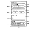
図2は図1に示した制御部で実行されるプロトコル・スイートの一例を示す図である。本実施形態では、プロトコル・スイートがインターネット・プロトコル・スイートの場合とする。 FIG. 2 is a diagram showing an example of a protocol suite executed by the control unit shown in FIG. In the present embodiment, it is assumed that the protocol suite is an Internet protocol suite.
図2に示すプロトコル・スイートがメモリ184に予め格納されている。プロトコル・スイートはメモリ184の代わりに記憶部190に予め格納されていてもよく、この場合、CPU182の実行対象となるプロトコルが記憶部190からメモリ184に読み出される。図2では、プロトコル・スイートに含まれる複数のプロトコルを、階層化された複数の通信層に分類して表示している。
The protocol suite shown in FIG. 2 is stored in the
プロトコル・スイートは、リンク層L001、インターネット層L002、トランスポート層L003、およびアプリケーション層L004を有する。 The protocol suite has a link layer L001, an Internet layer L002, a transport layer L003, and an application layer L004.
リンク層L001には、無線LAN(Local Area Network)プロトコルP110、WiMAX(Worldwide Interoperability for Microwave Access)プロトコルP120、およびLTE(Long Term Evolution)プロトコルP130が属する。インターネット層L002には、IP P210が属する。トランスポート層L003には、TCP P310およびUDP P320が属する。アプリケーション層L004には、動画アプリケーションソフトウェアプログラム(以下では、「動画アプリケーション」と称する)P410と、Webアプリケーション・ソフトウェアプログラム(以下では、「Webアプリケーション」と称する)P420とが属している。Webアプリケーションの一例としてWebブラウザがある。 A wireless LAN (Local Area Network) protocol P110, a WiMAX (Worldwide Interoperability for Microwave Access) protocol P120, and an LTE (Long Term Evolution) protocol P130 belong to the link layer L001. IP P210 belongs to the Internet layer L002. TCP P310 and UDP P320 belong to the transport layer L003. The application layer L004 includes a moving image application software program (hereinafter referred to as “moving image application”) P410 and a Web application software program (hereinafter referred to as “Web application”) P420. A web browser is an example of a web application.
図2に示すように、通信層は階層的に構成されており、隣り合う通信層とのみアクセスできるようになっている。例えば、アプリケーション層L004は、トランスポート層L003にアクセスすることができるが、インターネット層L002に直接アクセスすることはできない。インターネット層L002は、トランスポート層L003とリンク層L001にアクセスすることができるが、アプリケーション層L004と直接アクセスすることができない。 As shown in FIG. 2, the communication layers are hierarchically configured so that only the adjacent communication layers can be accessed. For example, the application layer L004 can access the transport layer L003 but cannot directly access the Internet layer L002. The Internet layer L002 can access the transport layer L003 and the link layer L001, but cannot directly access the application layer L004.
図2に示す4つの通信層において、最下層から最上層への処理の流れの方向を上り方向とし、最上層から最下層への処理の流れの方向を下り方向とする。 In the four communication layers shown in FIG. 2, the direction of processing flow from the lowermost layer to the uppermost layer is the upward direction, and the direction of processing flow from the uppermost layer to the lowermost layer is the downward direction.
なお、TCPの概要はRFC793に開示され、UDPの概要はRFC768に開示されているため、本実施形態では、これらのプロトコルについての詳細な説明を省略する。IPの概要については、RFC791に開示されているため、その詳細な説明を省略する。また、無線LANプロトコルの概要はIEEE802.11に開示され、WiMAXプロトコルの概要はIEEE802.16eに開示され、LTEプロトコルの概要は3GPP Release.8に開示されているため、これらのプロトコルの詳細な説明を省略する。 Note that an outline of TCP is disclosed in RFC 793 and an outline of UDP is disclosed in RFC 768. Therefore, detailed description of these protocols is omitted in this embodiment. Since the outline of IP is disclosed in RFC 791, detailed description thereof is omitted. An outline of the wireless LAN protocol is disclosed in IEEE 802.11, an outline of the WiMAX protocol is disclosed in IEEE 802.16e, and an outline of the LTE protocol is described in 3GPP Release. 8, detailed description of these protocols is omitted.
図2に示すプロトコル・スイートは一例であり、階層化された複数の通信層からなるプロトコル・スイートを備えていれば、図2に示したものと異なるアプリケーションソフトウェアプログラムおよびプロトコルを備えていてもよい。 The protocol suite shown in FIG. 2 is an example, and may include an application software program and a protocol different from those shown in FIG. 2 as long as the protocol suite includes a plurality of layered communication layers. .
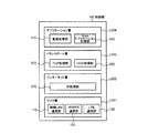
図3はCPUが図2に示したプロトコルを実行することで具現化される論理的な構成を示す機能ブロック図である。 FIG. 3 is a functional block diagram showing a logical configuration realized by the CPU executing the protocol shown in FIG.
制御部180は、アプリケーション層L004に分類される動画処理部410およびWebアプリケーション処理部420と、トランスポート層L003に分類されるTCP処理部310およびUDP処理部320と、インターネット層L002に分類されるIP処理部210と、リンク層L001に分類される無線LAN通信部110、WiMAX通信部120およびLTE通信部130とを有する。
The
動画処理部410はCPU182が動画アプリケーションP410を実行することで仮想的に構成され、Webアプリケーション処理部420はCPU182がWebアプリケーションP420を実行することで仮想的に構成される。
The moving
TCP処理部310はCPU182がTCP P310を実行することで仮想的に構成され、UDP処理部320はCPU182がUDP P320を実行することで仮想的に構成される。IP処理部210はCPU182がIP P210を実行することで仮想的に構成される。
The
無線LAN通信部110は、CPU182による無線LANプロトコルP110の実行と無線LAN専用の通信デバイスで構成される。WiMAX通信部120は、CPU182によるWiMAXプロトコルP120の実行とWiMAX専用の通信デバイスで構成される。LTE通信部130は、CPU182によるLTEプロトコルP130の実行とLTE専用の通信デバイスで構成される。
The wireless
制御部180は、図2に示したプロトコル・スイートを用いて図3に示した各部を制御することで、別の通信装置と通信することが可能である。以下では、説明を簡単にするために、図3の機能ブロック図に示した各構成の代わりに、図2に示したプロトコルまたはプログラムを動作の主体にして説明する。
The
ここで、通信装置100が他の通信装置と通信する場合を簡単に説明する。図4は2つの通信装置が通信する場合の情報処理方法を示す模式図である。 Here, a case where the communication apparatus 100 communicates with another communication apparatus will be briefly described. FIG. 4 is a schematic diagram showing an information processing method when two communication devices communicate with each other.
通信装置102は通信装置100と同様な構成である。 The communication device 102 has the same configuration as the communication device 100.
なお、図4では、リンク層L001内の無線LANプロトコルP110が通信装置100と通信装置102との間で直接通信する様子を示しているが、アクセスポイント(不図示)およびLAN(不図示)を経由する通信に経路を使用してもよく、特に通信形態は問わない。また、図4では、アプリケーション層L004内のアプリケーションについても、通信装置100と通信装置102との間で直接通信する様子を示しているが、サーバアプリケーション(不図示)を経由してもよい。他のプロトコルについても、上記の説明と同様に、直接に通信する場合に限定されない。 4 shows a state in which the wireless LAN protocol P110 in the link layer L001 directly communicates between the communication device 100 and the communication device 102, an access point (not shown) and a LAN (not shown) are used. A route may be used for communication that passes, and the communication form is not particularly limited. In addition, FIG. 4 shows a state in which applications in the application layer L004 are directly communicated between the communication device 100 and the communication device 102, but may also be via a server application (not shown). Other protocols are not limited to direct communication as in the above description.
図4に示すように、同一の通信層における同一のプロトコル同士で情報交換が行われる。実線および破線の双方向矢印は、各通信層におけるプロトコル間のやりとりを表現したものである。アプリケーション層L004を例に説明すると、WebアプリケーションP420で扱われるデータは通信装置100のWebアプリケーション処理部420で処理され、WebアプリケーションP421で扱われるデータは通信装置102のWebアプリケーション処理部420で処理される。実線の双方向矢印に示すように、WebアプリケーションP420、P421で扱われるデータは通信装置100と通信装置102のそれぞれのWebアプリケーション処理部420で処理される。また、破線の双方向矢印に示すように、動画アプリケーションP410で扱われるデータは通信装置100と通信装置102のそれぞれの動画処理部410で処理される。
As shown in FIG. 4, information exchange is performed between the same protocols in the same communication layer. The solid line and broken line double arrows represent the exchanges between protocols in each communication layer. The application layer L004 will be described as an example. Data handled by the web application P420 is processed by the web
実際には、例えば、WebアプリケーションP421で扱われるデータを通信装置100が通信装置102に送信する場合、そのデータは、通信装置100のアプリケーション層L004からトランスポート層L003およびインターネット層L002を順に経由してリンク層L001から通信装置102に送信される。通信装置102では、通信装置100から受信したデータは、リンク層L001からインターネット層L002およびトランスポート層L003を順に経由してアプリケーション層L004に至り、Webアプリケーション処理部420で処理される。その結果、通信層毎のデータ処理は図4の模式図に示すように表される。
Actually, for example, when the communication apparatus 100 transmits data handled by the Web application P421 to the communication apparatus 102, the data passes through the application layer L004, the transport layer L003, and the Internet layer L002 of the communication apparatus 100 in order. Is transmitted from the link layer L001 to the communication apparatus 102. In the communication apparatus 102, the data received from the communication apparatus 100 reaches the application layer L004 via the link layer L001, the Internet layer L002, and the transport layer L003 in order, and is processed by the Web
ここまで、通常の動作に関する制御部180の構成を説明したが、本実施形態の通信装置100に追加された、クロスレイヤアクセスの機能に関する構成を説明する。
The configuration of the
はじめに、クロスレイヤアクセスを、図5を参照して説明する。図5は図2に示したプロトコル・スイートをベースにしてクロスレイヤアクセスを説明するための図である。 First, cross-layer access will be described with reference to FIG. FIG. 5 is a diagram for explaining cross-layer access based on the protocol suite shown in FIG.
図5には、動画アプリケーションP410が、リンク層L001内の無線LANプロトコルP110、WiMAXプロトコルP120およびLTEプロトコルP130と、インターネット層L002内のIP P210と、トランスポート層L003内のTCP P310のそれぞれから情報を取得可能であることを上向きの破線矢印で示している。 In FIG. 5, the moving image application P410 receives information from the wireless LAN protocol P110, the WiMAX protocol P120 and the LTE protocol P130 in the link layer L001, the IP P210 in the Internet layer L002, and the TCP P310 in the transport layer L003. Is indicated by an upward broken arrow.
厳密に言うと、動画アプリケーションP410がTCP P310にアクセスするのは、隣り合う通信層との情報のやりとりなのでクロスレイヤアクセスに相当しないが、各プロトコルの情報について、隣り合う通信層との情報のやりとりであっても予めプロトコルで規定された通常のやりとり以外の場合も含めて、以下では、クロスレイヤアクセスと称する。 Strictly speaking, the video application P410 accessing the TCP P310 does not correspond to cross-layer access because it exchanges information with the adjacent communication layer, but information exchange between each protocol with the adjacent communication layer However, in the following, it is referred to as cross-layer access, including cases other than normal exchanges defined in advance by the protocol.
各プロトコルの情報とは、例えば、リンク層L001での無線環境における品質情報(再送数、信号電力強度など)、インターネット層L002でのルーティング情報および最大パケットサイズの情報、トランスポート層L003でのTCPウィンドウサイズおよび再送数などの情報である。 Information on each protocol includes, for example, quality information (number of retransmissions, signal power strength, etc.) in the wireless environment in the link layer L001, routing information and maximum packet size information in the Internet layer L002, and TCP in the transport layer L003. Information such as window size and number of retransmissions.
また、図5には、動画アプリケーションP410が、これらの情報を使ってトランスポート層L003内のTCP P310に最適なTCPウィンドウサイズを設定したり、リンク層L001で使用する回線を選ぶためにインターネット層L002内のIP P210にパラメータを設定したりすることが可能なことを下向きの破線矢印で示している。 Also, in FIG. 5, the moving picture application P410 uses this information to set an optimal TCP window size for the TCP P310 in the transport layer L003, or to select a line to be used in the link layer L001. The fact that it is possible to set parameters in the IP P210 in L002 is indicated by a downward dashed arrow.
動画アプリケーションP410と同様に、図5では、WebアプリケーションP420が、リンク層L001内の無線LANプロトコルP110、WiMAXプロトコルP120およびLTEプロトコルP130と、インターネット層L002内のIP P210と、トランスポート層L003内のTCP P310のそれぞれから情報を取得可能であることを上向きの矢印で示している。また、WebアプリケーションP420が、使用するリンク層での回線を選ぶためにインターネット層L002内のIP P210にパラメータを設定可能なことを下向きの矢印で示している。 Similar to the video application P410, in FIG. 5, the Web application P420 includes the wireless LAN protocol P110, the WiMAX protocol P120 and the LTE protocol P130 in the link layer L001, the IP P210 in the Internet layer L002, and the transport layer L003. An upward arrow indicates that information can be acquired from each TCP P310. In addition, a downward arrow indicates that the Web application P420 can set parameters in the IP P210 in the Internet layer L002 in order to select a link layer link to be used.
続いて、図5を参照して説明したクロスレイヤアクセスを実行可能にするための記憶部190および制御部180の構成を説明する。
Next, configurations of the
記憶部190には、制御部180が実行するプロトコルの処理手順を決めるための処理テーブルが格納されている。図6Aは通信層の上り方向の処理手順を決定するための上り処理テーブルの一例を示し、図6Bは通信層の下り方向の処理手順を決定するための下り処理テーブルの一例を示す。
The
各処理テーブルには複数種の処理手順が予め登録されており、各処理手順は管理番号で管理される。図6Aおよび図6Bに示すように、各処理テーブルは、管理番号に対応して、各通信層で使用されるプロトコルが記述されている。図6Aおよび図6Bに示す例では、管理番号が0からn(nは1以上の整数)までの(n+1)種の処理手順が登録されている。 A plurality of types of processing procedures are registered in advance in each processing table, and each processing procedure is managed by a management number. As shown in FIGS. 6A and 6B, each processing table describes a protocol used in each communication layer corresponding to a management number. In the example shown in FIGS. 6A and 6B, (n + 1) types of processing procedures from 0 to n (n is an integer of 1 or more) are registered.
各処理テーブルに示す通信層#001〜004のそれぞれはリンク層L001、インターネット層L002、トランスポート層L003およびアプリケーション層L004のそれぞれに相当する。 Each of communication layers # 001 to 004 shown in each processing table corresponds to a link layer L001, an Internet layer L002, a transport layer L003, and an application layer L004.
図6Aの上り処理テーブルを参照すると、例えば、管理番号が0の場合の処理手順では、通信層#L001で無線LANプロトコルP110を使用し、通信層#L002でIP P210を使用することがわかる。そして、通信層#L003で使用されるプロトコルは「selectable」となっている。この「selectable」は、予め規定された選択処理、すなわちIP P210で管理されるプロトコル番号で特定されるプロトコルを選択することを示す。通信層#L004で使用されるプロトコルも「selectable」となっている。これは、予め規定された選択処理、すなわちトランスポート層L003のプロトコルで管理されるポート番号でどのアプリケーションを選択するかを示している。 Referring to the uplink processing table in FIG. 6A, for example, in the processing procedure when the management number is 0, it is understood that the wireless LAN protocol P110 is used in the communication layer # L001 and the IP P210 is used in the communication layer # L002. The protocol used in the communication layer # L003 is “selectable”. This “selectable” indicates that a selection process defined in advance, that is, a protocol specified by a protocol number managed by the IP P210 is selected. The protocol used in the communication layer # L004 is also “selectable”. This indicates which application is selected with a port number managed in accordance with a predetermined selection process, that is, the protocol of the transport layer L003.
また、図6Aの上り処理テーブルにおいて、管理番号が2の場合の処理手順では、通信層#L001でWiMAXプロトコルP120を使用し、通信層#L004で動画アプリケーションP410を使用することがわかる。そして、通信層#L002で使用されるプロトコルは「NULL」となっている。この「NULL」は、その通信層では何も処理をせずに、メッセージを含むデータをそのまま次の通信層に渡すことを意味する。通信層#L003で使用されるプロトコルも「NULL」となっており、通信層#002の場合と同様である。
In the upstream processing table of FIG. 6A, it can be seen that in the processing procedure when the management number is 2, the WiMAX protocol P120 is used in the communication layer # L001 and the moving image application P410 is used in the communication layer # L004. The protocol used in the communication layer # L002 is “NULL”. This “NULL” means that data including the message is passed to the next communication layer as it is without any processing in the communication layer. The protocol used in the communication layer # L003 is also “NULL”, which is the same as in the
このようにして、各通信層間の接続情報と各通信層の処理動作の写像を通信単位でチェーンとして管理している。そして、管理番号に基づいて複数の通信層における一連の処理が鎖状に決定されるので、この一連の処理をチェーンと称する。また、管理番号がチェーンを特定するための番号であることから、以下では、管理番号をチェーン番号と称する場合もある。 In this way, connection information between communication layers and mapping of processing operations of each communication layer are managed as a chain in communication units. Since a series of processes in a plurality of communication layers are determined in a chain form based on the management number, this series of processes is referred to as a chain. In addition, since the management number is a number for specifying a chain, the management number may be referred to as a chain number below.
なお、本実施形態では、図6Aおよび図6Bに示したように、処理テーブルを上りと下りで別々に準備し、0からnまでの番号で(n+1)種の処理手順を管理する場合で説明したが、上りと下りのそれぞれの場合に応じて使用するプロトコルを特定できれば1つのテーブルであってもよい。また、処理手順を特定するための識別子は管理番号に限らず、通信相手のアドレスなど、制御部180が処理手順を特定できれば他の識別子でもよい。
In the present embodiment, as shown in FIGS. 6A and 6B, processing tables are prepared separately for upstream and downstream, and (n + 1) types of processing procedures are managed with numbers from 0 to n. However, one table may be used as long as the protocol to be used can be specified according to each of the uplink and downlink cases. In addition, the identifier for specifying the processing procedure is not limited to the management number, and other identifiers may be used as long as the
また、本実施形態では、処理手順を特定するための管理番号は、情報発信またはプロトコル制御したい発信元のプロトコルが付与し、必要な情報や制御情報を含むメッセージに含めるものとするが、通信装置100の通信相手から受信するデータに添付されていてもよく、管理番号の入手方法はこれらの場合に限らない。 In this embodiment, the management number for specifying the processing procedure is given by the protocol of the transmission source that wants to transmit information or control the protocol, and is included in a message that includes necessary information and control information. It may be attached to data received from 100 communication partners, and the method for obtaining the management number is not limited to these cases.
制御部180は、外部の装置からデータを受信すると、リンク層L001内のプロトコルを実行することで管理番号を設定する。そして、制御部180は、リンク層L001よりも上位の各通信層において、図6Aに示した処理テーブルを参照して管理番号に対応するチェーンを特定し、特定したチェーンにしたがって処理を実行する。ここでは、データを受信した際に常に管理番号を設定する例を示したが、既存の処理には手を付けず、クロスレイヤ処理をしたい場合にのみ管理番号を付与してもよい。またデータの受信にかかわらず、必要や要求に応じて情報を送信したり制御したりしたい場合に管理番号を付与してもよい。
When receiving data from an external device, the
また、制御部180は、外部の装置にデータを送信する際、データの種類や形式に応じてアプリケーション層L004内のアプリケーションを実行することで管理番号を決定する。そして、制御部180は、アプリケーション層L004よりも下位の各通信層において、図6Bに示した処理テーブルを参照して管理番号に対応するチェーンを特定し、特定したチェーンにしたがって処理を実行した後、データに管理番号を添付して外部の装置に送信する。ここでは、外部の装置にデータを送信する際に常に管理番号を設定する例を示したが、必要や要求に応じて情報を送信したり制御したりしたい場合に管理番号を付与してもよい。
In addition, when transmitting data to an external device, the
図7は各通信層において制御部がプロトコルを決定するための手順を示すフローチャートである。制御部180は、図2に示した4つの通信層のうち、外部の装置からデータを受信し、アプリケーションがデータを受信した場合には、リンク層L001からアプリケーション層L004まで、アプリケーションが外部の装置にデータを送信する場合には、アプリケーション層L004からリンク層L001まで、通信層毎に図7に示すフローの処理を行う。
FIG. 7 is a flowchart showing a procedure for the control unit to determine a protocol in each communication layer. The
ここでは、各通信層のプロトコルの種類がm(mは1以上の整数)個あるものとし、図7では、種類k(kは1以上m以下の任意の整数)のプロトコルを「#k」と表記している。例えば、図5を参照すると、インターネット層L002ではm=1であり、トランスポート層L003ではm=2である。 Here, it is assumed that there are m (m is an integer of 1 or more) protocol types in each communication layer, and in FIG. 7, the protocol of the type k (k is an arbitrary integer of 1 to m) is “#k”. It is written. For example, referring to FIG. 5, m = 1 in the Internet layer L002 and m = 2 in the transport layer L003.
各通信層において、制御部180は、処理テーブルを参照し、情報処理対象の通信層の情報と管理番号とに基づいて、どのプロトコルの処理をデータに対して行うか判定する(ステップCF01)。続いて、制御部180は、ステップCF01で決定したプロトコルの処理をデータに実行する(ステップCF02−1〜CF02−m)。ただし、ステップCF01で特定した内容が「NULL」である場合、制御部180は、データに対して何も処理しない(ステップCF02−(m+1))。
In each communication layer, the
次に、本実施形態の通信装置100の動作を説明する。 Next, the operation of the communication apparatus 100 of this embodiment will be described.
通信装置100が外部の装置からデータを受信したものとし、制御部180は、図6Aに示した処理テーブルを参照する。
It is assumed that the communication device 100 has received data from an external device, and the
図8は本実施形態の通信装置の動作を説明するための図である。図8では、図2に示したプロトコル・スイートの各通信層におけるプロトコル処理に加えて、隣り合う通信層の間で情報を振り分ける処理を模式的に示している。具体的には、通信層間の振り分け処理を行う通信層間インタフェースを図に示している。 FIG. 8 is a diagram for explaining the operation of the communication apparatus of this embodiment. FIG. 8 schematically shows processing for distributing information between adjacent communication layers in addition to the protocol processing in each communication layer of the protocol suite shown in FIG. Specifically, a communication layer interface for performing a communication layer distribution process is shown in the figure.
図8に示すインタフェースL012、L023、L034は、通信層間の処理を、わかり易く説明するために追加したものである。インタフェースL012、L023、L034は、制御部180が図7に示したステップCF01の処理を実行することで仮想的に構成される。
Interfaces L012, L023, and L034 shown in FIG. 8 are added for easy understanding of processing between communication layers. The interfaces L012, L023, and L034 are virtually configured by the
また、図8に示すように、RSS(Receive Signal Strength:受信信号強度)伝達機能P111が無線LANプロトコルP110内に設けられ、管理番号が2の場合に有効になることが予め設定されているものとする。RSS伝達機能P111は、無線LANプロトコルP110内で管理されている受信信号電力強度の値を、動画アプリケーションP410に伝える機能とする。この機能により、例えば、動画アプリケーションP410は、受信信号電力強度の値を動画品質の判定に使用することが可能となる。 Also, as shown in FIG. 8, an RSS (Receive Signal Strength) transmission function P111 is provided in the wireless LAN protocol P110, and it is set in advance to be effective when the management number is 2. And The RSS transmission function P111 is a function for transmitting the value of the received signal power intensity managed in the wireless LAN protocol P110 to the moving image application P410. With this function, for example, the moving image application P410 can use the value of the received signal power intensity for determination of moving image quality.
はじめに、図6Aおよび図8を参照して、通信装置100が実行するクロスレイヤ処理(レイヤスキップ)の場合を説明する。ここでは、管理番号が2の場合で説明する。 First, with reference to FIG. 6A and FIG. 8, the case of the cross layer process (layer skip) which the communication apparatus 100 performs is demonstrated. Here, a case where the management number is 2 will be described.
RSS伝送機能P111は、無線LANのフレームを外部から受信すると、フレームから受信信号電力強度の情報を読み出す。そして、RSS伝達機能P111は、管理番号「2」を設定し、上位層であるインターネット層L002宛にインタフェースL012を介して、管理番号を含むメッセージとともに受信信号電力強度のデータを送信する。 When the RSS transmission function P111 receives a wireless LAN frame from the outside, the RSS transmission function P111 reads information on received signal power intensity from the frame. Then, the RSS transmission function P111 sets the management number “2”, and transmits the received signal power strength data together with the message including the management number to the Internet layer L002, which is an upper layer, via the interface L012.
インタフェースL012は、RSS伝達機能P111を含む無線LANプロトコルP110からメッセージとともに受信信号電力強度のデータを受信すると、上り処理テーブルを参照し、メッセージに含まれる管理番号に基づいてチェーンを特定し、特定したチェーンにしたがって処理を分岐させる。 When the interface L012 receives the received signal power strength data together with the message from the wireless LAN protocol P110 including the RSS transmission function P111, the interface L012 refers to the uplink processing table, identifies the chain based on the management number included in the message, and identifies Branch processing according to chain.
図6Aに示した上り処理テーブルでは、管理番号が2の場合の通信層#002の欄が「NULL」なので、インターネット層L002では何も処理しない。インタフェースL012は、図7に示したステップCF02−(m+1)にしたがって、メッセージを含む受信信号電力強度のデータをIP P210に渡さずに、トランスポート層L003宛にインタフェースL023を介して送信する。
In the uplink processing table shown in FIG. 6A, since the column of the
インタフェースL023は、インタフェースL012からメッセージを含む受信信号電力強度のデータを受信すると、上り処理テーブルを参照し、メッセージに含まれる管理番号に基づいてチェーンを特定し、特定したチェーンにしたがって処理を分岐させる。 When the interface L023 receives the received signal power strength data including the message from the interface L012, the interface L023 refers to the uplink processing table, identifies the chain based on the management number included in the message, and branches the process according to the identified chain. .
図6Aに示した上り処理テーブルでは、管理番号が2の場合の通信層#003の欄が、通信層#002の欄と同様に、「NULL」なので、トランスポート層L003でも、何も処理しない。インタフェースL023は、図7に示したステップCF02−(m+1)にしたがって、メッセージを含む受信信号電力強度のデータをアプリケーション層L004宛にインタフェースL034を介して送信する。
In the uplink processing table shown in FIG. 6A, the field of the communication layer # 003 when the management number is 2 is “NULL” as in the field of the
インタフェースL034は、インタフェースL023からメッセージを含む受信信号電力強度のデータを受信すると、上り処理テーブルを参照し、メッセージに含まれる管理番号に基づいてチェーンを特定し、特定したチェーンにしたがって処理を分岐させる。 When the interface L034 receives the received signal power strength data including the message from the interface L023, the interface L034 refers to the uplink processing table, specifies the chain based on the management number included in the message, and branches the processing according to the specified chain. .
図6Aに示した上り処理テーブルでは、管理番号が2の場合の通信層#004の欄が「P410」なので、インタフェースL034は、受信信号電力強度のデータを動画アプリケーションP410に送信する。動画アプリケーションP410は、インタフェースL034から受信信号電力強度のデータを受け取ると、その値を動画品質の判定に使用する。 In the uplink processing table shown in FIG. 6A, since the field of the communication layer # 004 when the management number is 2 is “P410”, the interface L034 transmits the received signal power strength data to the moving image application P410. When receiving the received signal power intensity data from the interface L034, the moving image application P410 uses the value for determining the moving image quality.
管理番号が2の場合、上述したように、リンク層L001の無線LANプロトコルP110がアプリケーション層L004の動画アプリケーションP410に情報を送信することができる。このような処理手順で、インタフェースを共通にしたまま通信層を跨いで情報のやりとりを行うことが可能となる。 When the management number is 2, as described above, the wireless LAN protocol P110 of the link layer L001 can transmit information to the moving image application P410 of the application layer L004. With such a processing procedure, it is possible to exchange information across communication layers with a common interface.
次に、図6Aおよび図8を参照して、通信装置100が実行する、通常のデータパケット処理の場合を説明する。ここでは、管理番号が0の場合で説明する。 Next, with reference to FIG. 6A and FIG. 8, the case of normal data packet processing executed by the communication apparatus 100 will be described. Here, the case where the management number is 0 will be described.
リンク層L001内の無線LANプロトコルP110が、外部からデータパケットを受信すると、通常のデータパケット処理を行い、管理番号「0」を設定し、その管理番号を含むメッセージとともにデータパケットを上位層であるインターネット層L002宛にインタフェースL012に送信する。 When the wireless LAN protocol P110 in the link layer L001 receives a data packet from the outside, it performs normal data packet processing, sets a management number “0”, and sends the data packet together with a message including the management number to the upper layer. It transmits to the interface L012 addressed to the Internet layer L002.
インタフェースL012は、無線LANプロトコルP110からメッセージとともにデータパケットを受信すると、上り処理テーブルを参照し、メッセージに含まれる管理番号に基づいてチェーンを特定し、特定したチェーンにしたがって処理を分岐させる。 When the interface L012 receives the data packet together with the message from the wireless LAN protocol P110, the interface L012 refers to the uplink processing table, identifies the chain based on the management number included in the message, and branches the process according to the identified chain.
図6Aに示した上り処理テーブルでは、管理番号が0の場合の通信層#002の欄が「P210」なので、インタフェースL012は、メッセージを含むデータパケットをIP P210に送信する。IP P210は、インタフェースL012から受け取ったデータパケットに予め規定された処理を行った後、メッセージを含むデータパケットをトランスポート層L003宛にインタフェースL023を介して送信する。
In the uplink processing table shown in FIG. 6A, since the field of the
インタフェースL023は、IP P210からメッセージを含むデータパケットを受信すると、上り処理テーブルを参照し、メッセージに含まれる管理番号に基づいてチェーンを特定し、特定したチェーンにしたがって処理を分岐させる。 When the interface L023 receives the data packet including the message from the IP P210, the interface L023 refers to the uplink processing table, specifies the chain based on the management number included in the message, and branches the process according to the specified chain.
図6Aに示した上り処理テーブルでは、管理番号が0の場合の通信層#003の欄が「selectable」なので、インタフェースL023は管理番号だけでは送信先のプロトコルを特定できない。そこで、インタフェースL023は、IPヘッダに記述されたプロトコル番号を参照して、送信先のプロトコルを決定する(トランスポート層プロトコルの特定処理)。ここでは、プロトコル番号が「6」であるとすると、インタフェースL023は、送信先をTCP P310に決定し、TCP P310にメッセージを含むデータパケットを送信する。TCP P310は、インタフェースL023から受け取ったデータパケットに予め規定された処理を行った後、メッセージを含むデータパケットをアプリケーション層L004宛にインタフェースL034を介して送信する。ここでは、インタフェースL023が、IPヘッダを解析する場合で説明したが、IP P210内で通常実施される上述のトランスポート層プロトコルの特定処理の結果を受け取り、その結果に対応して処理を分岐させる、すなわちTCP P310にメッセージを含むデータパケットを送信することが可能である。 In the uplink processing table shown in FIG. 6A, the field of the communication layer # 003 when the management number is 0 is “selectable”, so the interface L023 cannot specify the destination protocol only by the management number. Therefore, the interface L023 refers to the protocol number described in the IP header to determine the destination protocol (transport layer protocol specifying process). Here, assuming that the protocol number is “6”, the interface L023 determines the transmission destination to be TCP P310 and transmits a data packet including a message to TCP P310. The TCP P310 performs a predetermined process on the data packet received from the interface L023, and then transmits the data packet including the message to the application layer L004 via the interface L034. Here, the interface L023 has been described in the case of analyzing the IP header. However, the interface L023 receives the result of the specific process of the above-described transport layer protocol that is normally performed in the IP P210, and branches the process according to the result. That is, it is possible to transmit a data packet including a message to TCP P310.
インタフェースL034は、TCP P310からメッセージを含むデータパケットを受信すると、上り処理テーブルを参照し、メッセージに含まれる管理番号に基づいてチェーンを特定し、特定したチェーンにしたがって処理を分岐させる。 When the interface L034 receives the data packet including the message from the TCP P310, the interface L034 refers to the uplink processing table, specifies the chain based on the management number included in the message, and branches the process according to the specified chain.
図6Aに示した上り処理テーブルでは、管理番号が0の場合の通信層#004の欄が通信層#003の場合と同様に「selectable」なので、インタフェースL034は管理番号だけでは送信先のプロトコルを特定できない。そこで、インタフェースL034は、TCPヘッダに記述されたポート番号を参照して、送信先のプロトコルを決定する(アプリケーション層プロトコルの特定処理)。ここでは、動画アプリケーション用に規定されたポート番号が「10000」であるとすると、インタフェースL034は、送信先を動画アプリケーションP410に決定し、動画アプリケーションP410にメッセージを含むデータパケットを送信する。動画アプリケーションP410は、インタフェースL034からデータパケットを受け取ると、データパケットを処理して動画を表示部(不図示)に表示させる。 In the uplink processing table shown in FIG. 6A, the field of the communication layer # 004 when the management number is 0 is “selectable” as in the case of the communication layer # 003. It can not be identified. Therefore, the interface L034 refers to the port number described in the TCP header and determines the destination protocol (application layer protocol specifying process). Here, assuming that the port number defined for the moving image application is “10000”, the interface L034 determines the transmission destination as the moving image application P410, and transmits a data packet including a message to the moving image application P410. When receiving the data packet from the interface L034, the moving image application P410 processes the data packet and displays the moving image on a display unit (not shown).
ここでは、インタフェースL034が、TCPヘッダを解析する場合で説明したが、TCP P310内で通常実施される上述のアプリケーション層プロトコルの特定処理の結果を受け取り、その結果に対応して処理を分岐させる、すなわち動画アプリケーションP410にメッセージを含むデータパケットを送信することが可能である。 Here, the interface L034 has been described in the case of analyzing the TCP header. However, the interface L034 receives the result of the specific process of the above-described application layer protocol normally performed in the TCP P310, and branches the process in accordance with the result. That is, it is possible to transmit a data packet including a message to the moving image application P410.
管理番号が0である場合、クロスレイヤではなく、階層順に通常のプロトコル処理を行うことができる。このような処理手順で既存のデータパケットをアプリケーションに届けること可能となる。 When the management number is 0, normal protocol processing can be performed in hierarchical order instead of the cross layer. An existing data packet can be delivered to the application by such a processing procedure.
なお、上述の動作の説明において、インタフェースおよびプロトコルの間で「データを送信する」と表現したが、実際にはインタフェースおよびプロトコルが記憶部190にデータを記憶させ、データの格納場所を示す情報(例えば、アドレスなど)を互いにやりとりしてもよい。また、ここでは上り方向の処理例を示したが下り方向も同様にして実現することが可能であり、その詳細な説明を省略する。
In the above description of the operation, the expression “transmits data” between the interface and the protocol. However, in actuality, the interface and protocol store the data in the
次に、本実施形態の通信装置100による情報処理方法の効果を説明する。 Next, the effect of the information processing method by the communication apparatus 100 of this embodiment is demonstrated.
本実施形態では、各通信層間でやりとりする情報をイベントと規定し、各通信層の動作を、イベント受信、イベント処理およびイベント送信という要素からなるイベントモデルで表現し、各通信層間の接続情報と各通信層の処理動作の写像を通信単位でチェーンとして管理している。そして、通信層をまたがる際にチェーンを参照し、各通信層内での処理を分岐させることで、各通信層間で自由にアクセスすることを可能にしている。 In this embodiment, information exchanged between each communication layer is defined as an event, and the operation of each communication layer is expressed by an event model including elements of event reception, event processing, and event transmission. Mapping of processing operations of each communication layer is managed as a chain in communication units. Then, when crossing the communication layers, the chain is referred to, and the processing within each communication layer is branched to allow free access between the communication layers.
そのため、各通信層が独立してイベントモデルとして動作し、複数の通信層の処理が総合的に最適化されるため、複数のアプリケーションが動作し、自由に入れ替えられるような環境下でも、無駄な処理を省いて、全体として最適化される。イベントとは、例えば、管理番号を含むメッセージと処理対象のデータの情報である。 Therefore, each communication layer operates independently as an event model, and processing of multiple communication layers is comprehensively optimized. Therefore, even in an environment where multiple applications operate and can be freely replaced, it is useless. It is optimized as a whole without processing. The event is, for example, information on a message including a management number and data to be processed.
また、クロスレイヤ処理の追加に際して、各通信層のインタフェースを増やすことなく、広い拡張性、移植の容易性を有している。その理由は、各通信層内にクロスレイヤ処理を追加し、その処理は整理、規定された共通に使用できるクロスレイヤインタフェースを利用できるからである。 Further, when adding cross-layer processing, it has wide expandability and portability without increasing the interfaces of each communication layer. The reason is that a cross-layer process is added to each communication layer, and the process can be organized and defined and used in common and can be used in common.
さらに、複数のアプリケーションが動作し、自由に入れ替えられるような環境でも、アプリケーションの通信処理単位で各通信層へ情報を伝えることができる。例えば、リンク層で切断イベントが発生した場合に、アプリケーションの通信処理に対して迅速に通知することが可能である。その理由は、チェーンで管理されたクロスレイヤアクセスが提供されるため、各プロトコルにおいて、チェーンの使用を管理でき、チェーンにしたがって、使用中のチェーンの宛先を参照して複数のアプリケーションへ同報、または1つのアプリケーションへ通知できるからである。 Furthermore, even in an environment in which a plurality of applications operate and can be freely replaced, information can be transmitted to each communication layer in units of application communication processing. For example, when a disconnection event occurs in the link layer, it is possible to quickly notify the communication processing of the application. The reason for this is that chain-managed cross-layer access is provided, so that each protocol can manage chain usage, refer to the destination of the chain in use, and broadcast to multiple applications according to the chain. This is because one application can be notified.
なお、各通信層のプロトコルの処理と、図7に示したステップCF01の処理(図8のインタフェースに相当)の処理とを別々のハードウェアで実行させるようにしてもよい。例えば、各プロトコルに対応した専用の集積回路を設け、CPU182にインタフェースの処理だけを実行させてもよい。このことは第2の実施形態においても同様である。
Note that the protocol processing of each communication layer and the processing of step CF01 (corresponding to the interface of FIG. 8) shown in FIG. 7 may be executed by separate hardware. For example, a dedicated integrated circuit corresponding to each protocol may be provided, and the
(第2の実施形態)
本実施形態では、各通信層で実行される処理として、プロトコル内に含まれる機能単位で選択を可能にしたものである。
(Second Embodiment)
In the present embodiment, the processing executed in each communication layer enables selection in units of functions included in the protocol.
本実施形態の通信装置100の構成を説明する。本実施形態では、第1の実施形態と異なる点を詳しく説明し、第1の実施形態と同様な構成についての詳細な説明を省略する。 A configuration of the communication apparatus 100 according to the present embodiment will be described. In the present embodiment, differences from the first embodiment will be described in detail, and a detailed description of the same configuration as that of the first embodiment will be omitted.
図9は本実施形態におけるプロトコル・スイートを説明するための図である。図9は図2に示したプロトコル・スイートをベースに、各プロトコルに含まれる機能を詳細に模式的に表したものである。 FIG. 9 is a diagram for explaining a protocol suite in this embodiment. FIG. 9 schematically shows in detail the functions included in each protocol based on the protocol suite shown in FIG.
図9に示すように、動画アプリケーションP410は機能F411〜F415を有する。WebアプリケーションP420は機能F431〜F423を有する。TCP P310は機能F311〜F314を有する。UDP P320は機能F321〜F323を有する。IP P210は機能F211〜F215を有する。無線LANプロトコルP110は機能F111〜F114を有する。WiMAXプロトコルP120は機能F121〜F123を有する。 As shown in FIG. 9, the moving image application P410 has functions F411 to F415. The Web application P420 has functions F431 to F423. TCP P310 has functions F311 to F314. The UDP P320 has functions F321 to F323. The IP P210 has functions F211 to F215. The wireless LAN protocol P110 has functions F111 to F114. The WiMAX protocol P120 has functions F121 to F123.
次に、本実施形態における制御部180がプロトコルに含まれる機能を、どのように管理し、実行するかを説明する。図10は制御部によるプロトコル内の機能の実行の手順を示すフローチャートである。
Next, how the
プロトコル内の機能F121〜F423を、例えば、図10に示すような処理フローの集まりで表すことができる。つまり、プロトコルは、図10に示す処理フローにおけるステップを1以上実行することによって構成されていると考えることができる。本実施形態では、プロトコル内の各機能を、図10に示すように、イベント受信処理A001、イベント処理A002およびイベント送信処理A003の要素からなるイベントモデルに分類することで、機能毎に管理しやすくしている。 Functions F121 to F423 in the protocol can be expressed by a collection of processing flows as shown in FIG. 10, for example. That is, it can be considered that the protocol is configured by executing one or more steps in the processing flow shown in FIG. In this embodiment, as shown in FIG. 10, each function in the protocol is classified into an event model including elements of event reception processing A001, event processing A002, and event transmission processing A003, so that each function can be easily managed. doing.
図10では、イベント受信処理A001、イベント処理A002およびイベント送信処理A003を順に行う場合を示している。制御部180があるプロトコル内でイベント受信処理に続いてイベント処理を実行するが、機能によっては、その後、イベント送信処理を行わない場合があってもよい。また、制御部180がイベント受信処理を行うが、イベント処理を実行せずに、イベント送信処理を行ってもよい。
FIG. 10 shows a case where event reception processing A001, event processing A002, and event transmission processing A003 are performed in order. The
次に、記憶部190に格納されている処理テーブルの構成を説明する。
Next, the configuration of the processing table stored in the
記憶部190には、制御部180が実行するプロトコルの処理手順を決めるための処理テーブルが格納されている。図11は通信層の上り方向の処理手順を決定するための上り処理テーブルの一例を示す。
The
処理テーブルには複数種の処理手順が予め登録されており、各処理手順は管理番号で管理される。図11に示すように、処理テーブルは、管理番号に対応して、各通信層で使用される機能が記述されている。図11に示す例では、管理番号が0からn(nは1以上の整数)までの(n+1)種の処理手順が登録されている。
A plurality of types of processing procedures are registered in advance in the processing table, and each processing procedure is managed by a management number. As shown in FIG. 11, the processing table describes functions used in each communication layer corresponding to the management number. In the example shown in FIG. 11, (n + 1) types of processing procedures with
図11の上り処理テーブルを参照すると、例えば、管理番号が0の場合の処理手順では、通信層#L001で無線LANプロトコルP110内の機能F111〜F113を使用するチェーンが規定されている。そして、通信層#L002ではIP P210内の機能F211〜F215を使用するチェーン、通信層#L003ではTCP P310内の機能F311〜F314を使用するチェーン、通信層#L004では動画アプリケーションP410内の機能F411〜F414を使用するチェーンが規定されている。 Referring to the uplink processing table in FIG. 11, for example, in the processing procedure when the management number is 0, a chain that uses the functions F111 to F113 in the wireless LAN protocol P110 is defined in the communication layer # L001. In the communication layer # L002, a chain using the functions F211 to F215 in the IP P210, in the communication layer # L003, a chain using the functions F311 to F314 in the TCP P310, and in the communication layer # L004, a function F411 in the video application P410. A chain using ~ F414 is defined.
このようにして、本実施形態では、通信層間の接続情報および各通信層の処理動作だけでなく、各通信層のプロトコル内でどの機能を順に使用するかをチェーンとして管理している。 In this way, in this embodiment, not only the connection information between communication layers and the processing operation of each communication layer, but also which function is used in sequence within the protocol of each communication layer is managed as a chain.
なお、本実施形態では、上り処理テーブルの構成を説明したが、下り処理テーブルも図11に示したテーブルと同様であり、その詳細な説明を省略する。 In the present embodiment, the configuration of the upstream processing table has been described. However, the downstream processing table is the same as the table shown in FIG. 11, and detailed description thereof is omitted.
また、第1の実施形態と同様に、処理テーブルを上りと下りで別々に準備する場合で説明したが、上りと下りのそれぞれの場合に応じて使用する機能を特定できれば1つのテーブルであってもよい。また、処理手順を特定するための識別子は管理番号に限らず、通信相手のアドレスなど、制御部180が処理手順を特定できれば他の識別子でもよい。
Further, as in the first embodiment, the processing table is described as being prepared separately for uplink and downlink. However, if a function to be used can be specified according to each case of uplink and downlink, the table is a single table. Also good. In addition, the identifier for specifying the processing procedure is not limited to the management number, and other identifiers may be used as long as the
次に、本実施形態の通信装置100の動作を説明する。 Next, the operation of the communication apparatus 100 of this embodiment will be described.
通信装置100が外部の装置からデータを受信したものとし、制御部180は、図11に示した処理テーブルを参照する。ここでは、管理番号が1の場合で説明する。
It is assumed that the communication device 100 has received data from an external device, and the
管理番号が1の場合、図11に示すように、機能F113、F114、F415を使用する上りチェーンであることがわかる。ここで、通信層間のインタフェースは図8に示したものと同様とする。 When the management number is 1, as shown in FIG. 11, it can be seen that this is an uplink chain that uses the functions F113, F114, and F415. Here, the interface between the communication layers is the same as that shown in FIG.
機能F114には、管理番号が1のチェーンを使用することが予め設定されている。または、機能F114は処理テーブルを検索することでチェーンを特定してもよい。検索してチェーンを特定する場合では、機能F114は、動作を実行するときに処理テーブルを参照して、通信層#L001に自身の番号であるF114が存在するチェーンを検索する。検索の結果、機能F114は、図11に示す処理テーブルから管理番号が1のチェーンを使用することを認識できる。 In the function F114, use of a chain having a management number of 1 is set in advance. Alternatively, the function F114 may specify a chain by searching the processing table. In the case of specifying a chain by searching, the function F114 refers to the processing table when executing the operation and searches for a chain in which the communication layer # L001 has its own number F114. As a result of the search, the function F114 can recognize that the chain whose management number is 1 is used from the processing table shown in FIG.
通信装置100が外部から無線LANプロトコルP110を介してデータを受信すると、無線LANプロトコルP110は機能F114に処理を実行させる。機能F114は、処理テーブルで管理番号「1」のチェーンを参照し、機能F113に処理を実行させる。機能F113は機能F114からデータを受信すると、処理を実行した後、上位層であるインターネット層L002宛にインタフェースL012を介して、管理番号を含むメッセージとともにデータを送信する。 When the communication apparatus 100 receives data from the outside via the wireless LAN protocol P110, the wireless LAN protocol P110 causes the function F114 to execute processing. The function F114 refers to the chain with the management number “1” in the process table and causes the function F113 to execute the process. When the function F113 receives the data from the function F114, the function F113 transmits the data together with the message including the management number to the Internet layer L002, which is an upper layer, via the interface L012, after executing the process.
インタフェースL012は、機能F113からメッセージとともにデータを受信すると、上り処理テーブルを参照し、メッセージに含まれる管理番号に基づいてチェーンを特定し、特定したチェーンにしたがって処理を行う。 When the interface L012 receives the data together with the message from the function F113, the interface L012 refers to the uplink processing table, identifies the chain based on the management number included in the message, and performs processing according to the identified chain.
図11に示した上り処理テーブルでは、管理番号が1の場合の通信層#002の欄が「NULL」なので、インターネット層L002では何も処理しない。インタフェースL012は、メッセージを含むデータをトランスポート層L003宛にインタフェースL023を介して送信する。
In the uplink processing table shown in FIG. 11, the column of the
インタフェースL023は、インタフェースL012からメッセージを含むデータを受信すると、上り処理テーブルを参照し、メッセージに含まれる管理番号に基づいてチェーンを特定し、特定したチェーンにしたがって処理を行う。 When the interface L023 receives data including a message from the interface L012, the interface L023 refers to the uplink processing table, specifies a chain based on the management number included in the message, and performs processing according to the specified chain.
図11に示した上り処理テーブルでは、管理番号が1の場合の通信層#003の欄が、通信層#002の欄と同様に、「NULL」なので、トランスポート層L003でも、何も処理しない。インタフェースL023は、メッセージを含むデータをアプリケーション層L004宛にインタフェースL034を介して送信する。
In the uplink processing table shown in FIG. 11, the communication layer # 003 column when the management number is 1 is “NULL” as in the
インタフェースL034は、インタフェースL023からメッセージを含むデータを受信すると、上り処理テーブルを参照し、メッセージに含まれる管理番号に基づいてチェーンを特定し、特定したチェーンにしたがって処理を行う。 When the interface L034 receives data including a message from the interface L023, the interface L034 refers to the uplink processing table, specifies a chain based on the management number included in the message, and performs processing according to the specified chain.
図11に示した上り処理テーブルでは、管理番号が1の場合の通信層#004の欄が「機能F415」なので、インタフェースL034は、データを動画アプリケーションP410に送信する。動画アプリケーションP410は、インタフェースL034からデータを受け取ると、機能F415に処理を実行させる。このような処理手順で、インタフェースを共通にしたまま通信層を跨いで情報をやりとりし、通信層を跨いで処理を行うことが可能となる。 In the uplink processing table shown in FIG. 11, since the field of communication layer # 004 when the management number is 1 is “function F415”, the interface L034 transmits data to the moving image application P410. When receiving the data from the interface L034, the moving image application P410 causes the function F415 to execute processing. With such a processing procedure, it is possible to exchange information across communication layers with a common interface, and to perform processing across communication layers.
図11に示す処理テーブルにおいて、管理番号がnのチェーンと管理番号が0のチェーンを比較してみる。管理番号がnの場合では、管理番号が0の場合の通信層#L001〜通信層#L003のチェーンから機能F112、機能F212、機能F213、機能F214、機能F312および機能F313を「NULL」によってスキップさせていることがわかる。
In the processing table shown in FIG. 11, the chain with the management number n is compared with the chain with the
このようにして、本実施形態では、プロトコル内の一部の機能をスキップさせる処理を簡単に実現することができる。 In this way, in the present embodiment, it is possible to easily realize processing for skipping some functions in the protocol.
また、ここでは省略したが、図11に示した処理テーブルにおける機能設定の欄に「selectable」設定することで、各機能において特定した次の通信層のプロトコルに向けて処理を継続することも可能である。 Although omitted here, by setting “selectable” in the function setting column in the processing table shown in FIG. 11, it is possible to continue processing for the protocol of the next communication layer specified in each function. It is.
以下に、プロトコルに含まれる機能の例と、プロトコルの機能の一部の処理をスキップする場合の具体例を説明する。 Hereinafter, an example of functions included in the protocol and a specific example in the case of skipping part of the processing of the protocol functions will be described.
本実施例は、TCPにおけるセッション設定処理の場合である。 This embodiment is a case of session setting processing in TCP.
アプリケーションの機能がOS(Operating System)へ通信開始のためのシステムコールを行うと、TCPのセッション設定機能が選択される。セッション設定機能は、通信相手にSYNパケットを送信し、Ackパケットを受け取る処理、または、SYNパケットを相手から受け取り、Ackパケットを送信する処理を行う。これが、アプリケーションがTCPセッションを開始するときの流れとなり、処理テーブル内のチェーンで実現される。 When an application function makes a system call for starting communication to an OS (Operating System), a TCP session setting function is selected. The session setting function performs a process of transmitting a SYN packet to a communication partner and receiving an Ack packet, or a process of receiving a SYN packet from the partner and transmitting an Ack packet. This is a flow when an application starts a TCP session, and is realized by a chain in the processing table.
ここで、もし通信装置が1対1のセッションしか必要としない場合、すなわち通信装置にアプリケーションが1つしかなくセッションが1本あればよい場合、電源投入直後から決まったポート番号を使用して通信すればよいため、TCPのSYN処理は不要となる。これを実現するには、セッション設定機能は不要とするために、処理テーブル内のチェーンを利用してスキップするだけでよい。 Here, if the communication device only needs a one-to-one session, that is, if the communication device has only one application and only one session is required, communication is performed using a predetermined port number immediately after the power is turned on. Therefore, the TCP SYN process is not necessary. In order to realize this, since the session setting function is unnecessary, it is only necessary to skip using a chain in the processing table.
本実施例は、TCPにおけるウィンドウ制御の場合である。 This embodiment is a case of window control in TCP.
TCPにおいて、受信側から伝送されるAckヘッダのWINDOWフィールドに、受信側が受信可能なオクテット数が入る。送信側は、そのオクテット数を超えないデータサイズを次回送信する。一般的にはTCP通信開始時点では通信装置間の伝送品質が不明であるため、当初のオクテット数は小さい値として受信側はAckを送信側に返送する。その後に送信側から送られてきたパケットのチェックサム検査により、伝送品質がよいと判断された場合にのみ、受信側は、WINDOWフィールドの値を増加させたAckを返送し、結果的に送信側がより大きなオクテット数を含むデータを送ることとなる。 In TCP, the number of octets that can be received by the receiving side is entered in the WINDOW field of the Ack header transmitted from the receiving side. The transmitting side transmits the data size not exceeding the number of octets next time. Generally, since the transmission quality between communication devices is unknown at the start of TCP communication, the receiving side returns Ack to the transmitting side with the initial number of octets being small. Only when the transmission quality is judged to be good by the checksum check of the packet sent from the transmission side after that, the reception side returns Ack with the value of the WINDOW field increased. As a result, the transmission side Data containing a larger number of octets will be sent.
ここで、もし受信側が当初から伝送品質が良いとわかっており、かつ、受信側のバッファサイズも十分に準備されていれば、受信側はTCPのパケットを受信するたびにWINDOWフィールドの値を増減する必要はなく、受信パケットのチェックサム処理を処理テーブル内のチェーンを利用してスキップし、予め決められた大きな固定値をWINDOWフィールドに設定すればよい。 Here, if the receiving side knows that the transmission quality is good from the beginning and the buffer size on the receiving side is sufficiently prepared, the receiving side increases or decreases the value of the WINDOW field every time a TCP packet is received. It is not necessary to perform the checksum processing of the received packet by using the chain in the processing table, and a predetermined large fixed value may be set in the WINDOW field.
万が一、通信装置間の伝送路に障害が発生した場合は、例えば、受信側が、リンク層のエラー検出機能から得られる値を参照、蓄積および統計処理などを行い、その値が予め決められた閾値を超えたときのみ、WINDOWフィールドの値を適切なオクテット数減らす処理を行えばよい。こうすることにより、通信開始時点から、低処理量で高速なTCP通信が可能となる。 Should a failure occur in the transmission path between communication devices, for example, the receiving side refers to the value obtained from the error detection function of the link layer, performs accumulation and statistical processing, and the value is a predetermined threshold value. Only when the value exceeds, the value of the WINDOW field should be reduced by an appropriate number of octets. By doing so, it is possible to perform high-speed TCP communication with a low processing amount from the communication start time.
その反対に、受信側が当初から伝送品質が悪いとわかっている場合、WINDOW制御を行っても得る効果は少ない。そのため、受信側は、初めから少ない固定値のオクテット数をWINDOWフィールドに設定し、処理テーブル内のチェーンを利用して、WINDOW制御をスキップすれば、TCP通信を低処理で行うことが可能となる。つまり、WINDOWフィールドを微小に増減しかできないWINDOW制御を省略することで、通信装置間で数多く行われるTCP処理を共通化することが可能となる。 On the other hand, when the receiving side knows that the transmission quality is poor from the beginning, the effect obtained by performing the WINDOW control is small. Therefore, if the receiving side sets a small number of octets in the WINDOW field from the beginning and skips WINDOW control using the chain in the processing table, TCP communication can be performed with low processing. . In other words, by omitting the WINDOW control that can only slightly increase / decrease the WINDOW field, it becomes possible to share many TCP processes performed between communication apparatuses.
次に、図12を参照して、エラーチェックのクロスレイヤ処理について説明する。 Next, error check cross-layer processing will be described with reference to FIG.
図12は図9に示したプロトコル・スイートのうち、エラーチェック処理に着目して機能を記述したものである。 FIG. 12 describes functions in the protocol suite shown in FIG. 9 while focusing on error check processing.
リンク層L001における無線LANプロトコルP110は、パケットのエラーチェックを行うWLANエラーチェック機能F112を有する。具体的には、WLANエラーチェック機能F112は、通信装置100が無線LANパケットを受信した際、そのパケット内のCRCフィールドの値がパケット全体から計算したCRC(巡回冗長検査)と等しいか否かを確認し、それらの値が一致しなければ、基本的にそのパケットは破棄するという機能である。 The wireless LAN protocol P110 in the link layer L001 has a WLAN error check function F112 that performs a packet error check. Specifically, when the communication apparatus 100 receives a wireless LAN packet, the WLAN error check function F112 determines whether the CRC field value in the packet is equal to a CRC (Cyclic Redundancy Check) calculated from the entire packet. The function is to confirm and basically discard the packet if the values do not match.
また、インターネット層L002のIP P210は、パケットのエラーチェックを行うIPエラーチェック機能F214を有する。具体的には、IPエラーチェック機能F214は、パケット内のIPヘッダ部分に対して1の補数和の1の補数を計算し、チェックサムの値と比較することでエラーをチェックする。 Further, the IP P210 of the Internet layer L002 has an IP error check function F214 that performs packet error check. Specifically, the IP error check function F214 calculates the one's complement of the one's complement sum for the IP header portion in the packet, and checks the error by comparing it with the checksum value.
IPと同様にTCPにも、パケットのエラーチェックを行うTCPエラーチェック機能F312がある。具体的には、TCPエラーチェック機能F312は、パケット内のTCPヘッダとペイロード部分に対して1の補数和の1の補数を計算する処理である。 Similar to IP, TCP has a TCP error check function F312 that performs packet error check. Specifically, the TCP error check function F312 is a process of calculating the one's complement of the one's complement sum for the TCP header and payload portion in the packet.
ここで、IPエラーチェック機能F214とTCPエラーチェック機能F312は、その対象こそ異なるものの、処理内容は同じである。そこで、例えば、処理テーブル内で規定されたTCPエラーチェック処理F312の代わりに、IPエラーチェック機能F214を利用してもよい。すなわち処理テーブル内でTCPエラーチェック機能F312の代わりにIPエラーチェック機能F214を実行するように規定しておけば、TCPエラーチェック機能F312をIPエラーチェック機能F214に置き換えることができる。このようにすることで、各プロトコル内で共通的な処理をまとめることができる。 Here, although the IP error check function F214 and the TCP error check function F312 are different in their objects, the processing contents are the same. Therefore, for example, the IP error check function F214 may be used instead of the TCP error check process F312 defined in the process table. That is, if it is specified in the processing table that the IP error check function F214 is executed instead of the TCP error check function F312, the TCP error check function F312 can be replaced with the IP error check function F214. By doing in this way, common processes within each protocol can be collected.
本実施形態によれば、第1の実施形態で説明した効果の他に、以下のような効果を得ることができる。 According to the present embodiment, in addition to the effects described in the first embodiment, the following effects can be obtained.
本実施形態では、イベントとチェーンによって、プロトコルの機能の使用有無を自在に決定することができる。例えば、通信層をスキップするようなクロスレイヤアクセスまたは通信層の一部機能をスキップする処理がチェーン上「NULL」と表現するだけで可能となる。 In the present embodiment, whether or not the protocol function is used can be freely determined by the event and the chain. For example, cross-layer access that skips the communication layer or processing that skips a part of the functions of the communication layer can be performed simply by expressing “NULL” on the chain.
また、イベントとチェーンによって、プロトコル内の機能の使用有無、処理順序などを自在に変更することができる。例えば、プロトコルのフルセットを実行することや、プロトコルの一部のみを実行、さらには異なる機能を組み合わせて新たなプロトコルの機能を実行することが容易である。 In addition, the use of functions in the protocol, the processing order, and the like can be freely changed according to events and chains. For example, it is easy to execute a full set of protocols, execute only a part of the protocol, or combine different functions to execute new protocol functions.
さらに、チェーンによって、プロトコル内の機能のうち、共通的な処理をまとめて各プロトコルで指定して使うことができる。例えば、暗号化処理やデータのエラーチェック処理などの計算処理を個々のプロトコルで準備しておくことが不要となる。 Furthermore, common processing among the functions in the protocol can be specified and used in each protocol by the chain. For example, it is not necessary to prepare calculation processing such as encryption processing and data error check processing using individual protocols.
上述の実施形態および実施例では、本発明の通信装置をわかり易く説明するために、構成および動作を具体的に説明したが、本発明の通信装置は少なくとも次のような特徴を有している。 In the above-described embodiments and examples, the configuration and operation have been specifically described in order to easily understand the communication device of the present invention. However, the communication device of the present invention has at least the following features.
図13は本発明の一実施形態の通信装置の構成例を示すブロック図である。 FIG. 13 is a block diagram illustrating a configuration example of a communication apparatus according to an embodiment of the present invention.
図13に示すように、本発明の一実施形態の通信装置101は制御部180を有する。制御部180は、階層化された複数の通信層を介して外部の通信装置とデータを送受信する際、各通信層間でやりとりする情報をイベントと規定し、各通信層のプロトコルの処理動作を、イベント受信、イベント処理およびイベント送信という要素からなるイベントモデルで管理し、イベントモデルの単位で処理を実行する。制御部180は、通信層間でのデータのやりとりおよび各通信層でのプロトコル処理をイベントモデルの単位で実行することで、ある通信層においてイベント受信の後にイベント送信が規定されていれば、その通信層でプロトコル処理を行わずに次の通信層にデータを引き渡すクロスレイヤ処理が可能となる。
As illustrated in FIG. 13, the communication apparatus 101 according to the embodiment of the present invention includes a
本発明の通信制御方法を、電気通信の分野に属し、送信される情報および/または受信される情報を処理するために通信層(プロトコル・スタック/スイート)を用いるような通信システムの分野に適用することが可能である。 The communication control method of the present invention belongs to the field of telecommunications and is applied to the field of communication systems that use a communication layer (protocol stack / suite) to process transmitted and / or received information. Is possible.
100、101 通信装置
180 制御部
190 記憶部
100, 101
Claims (6)
前記階層化された複数の通信層を介して外部の通信装置とデータを送受信する際、各通信層間でやりとりする情報をイベントと規定し、各通信層のプロトコルの処理動作を、前記イベントモデルで管理し、前記テーブルを用いて、各通信層間の接続情報および各通信層の処理動作の写像を通信単位でチェーンとして管理し、前記イベント受信時に前記テーブルを参照して前記チェーンにしたがって、各通信層内のプロトコルに含まれる機能のうち、どの機能を使用するかを決定して実行する制御部を有する通信装置。 A memory storing a table describing functions included in the protocol for managing protocol processing operations in a plurality of hierarchical communication layers by an event model including elements of event reception, event processing, and event transmission And
When transmitting / receiving data to / from an external communication device via the plurality of hierarchical communication layers, information exchanged between each communication layer is defined as an event, and the protocol processing operation of each communication layer is defined by the event model. And managing the connection information between each communication layer and the mapping of processing operations of each communication layer as a chain by communication unit using the table, and referring to the table when receiving the event, according to the chain A communication apparatus having a control unit that determines and executes which function to use among functions included in a protocol in a layer.
前記制御部は、
前記イベント受信時に前記テーブルを参照して前記チェーンにしたがって、各通信層内に含まれるプロトコルのうち、どのプロトコルを使用するかを決定する、通信装置。 The communication device according to claim 1.
The controller is
A communication device that determines which protocol to use among protocols included in each communication layer according to the chain with reference to the table when the event is received.
前記制御部は、
前記チェーンにしたがって、各通信層内のプロトコルの機能のうち、処理内容が同じ機能については異なる対象に共通に使用する、通信装置。 The communication device according to claim 1 or 2,
The controller is
A communication device that uses the same processing content among the functions of the protocol in each communication layer in accordance with the chain, and is commonly used for different objects.
前記制御部は、
前記イベント受信時に前記テーブルを参照して前記チェーンにしたがって、前記複数の通信層のうち、1以上の通信層の処理動作をスキップさせる、通信装置。 The communication device according to claim 1.
The controller is
A communication apparatus that skips processing operations of one or more communication layers among the plurality of communication layers according to the chain with reference to the table when the event is received.
前記階層化された複数の通信層を介して外部の通信装置とデータを送受信する際に、各通信層間でやりとりする情報をイベントと規定し、
各通信層のプロトコルの処理動作を、前記イベントモデルで管理し、
前記テーブルを用いて、各通信層間の接続情報および各通信層の処理動作の写像を通信単位でチェーンとして管理し、前記イベント受信時に前記テーブルを参照して前記チェーンにしたがって、各通信層内のプロトコルに含まれる機能のうち、どの機能を使用するかを決定して実行する、通信制御方法。 A memory storing a table describing functions included in the protocol for managing protocol processing operations in a plurality of hierarchical communication layers by an event model including elements of event reception, event processing, and event transmission A communication control method by a communication device having a unit,
When transmitting / receiving data to / from an external communication device via the hierarchical communication layers, information exchanged between the communication layers is defined as an event.
Manage the processing operation of each communication layer protocol with the event model,
Using the table, the connection information between the communication layers and the mapping of processing operations of the communication layers are managed as a chain in communication units, and when the event is received, the table is referred to according to the chain according to the chain. A communication control method that determines and uses which of the functions included in the protocol is used.
前記階層化された複数の通信層を介して外部の通信装置とデータを送受信する際に、各通信層間でやりとりする情報をイベントと規定する手順と、
各通信層のプロトコルの処理動作を、前記イベントモデルで管理する手順と、
前記テーブルを用いて、各通信層間の接続情報および各通信層の処理動作の写像を通信単位でチェーンとして管理し、前記イベント受信時に前記テーブルを参照して前記チェーンにしたがって、各通信層内のプロトコルに含まれる機能のうち、どの機能を使用するかを決定して実行する手順を前記コンピュータに実行させるためのプログラム。 A memory storing a table describing functions included in the protocol for managing protocol processing operations in a plurality of hierarchical communication layers by an event model including elements of event reception, event processing, and event transmission A computer having a
A procedure for defining information exchanged between each communication layer as an event when transmitting / receiving data to / from an external communication device via the plurality of hierarchical communication layers;
A procedure for managing the processing operation of each communication layer protocol by the event model,
Using the table, the connection information between the communication layers and the mapping of processing operations of the communication layers are managed as a chain in communication units, and when the event is received, the table is referred to according to the chain according to the chain. A program for causing a computer to execute a procedure of determining and executing which function is used among functions included in a protocol.
Priority Applications (1)
| Application Number | Priority Date | Filing Date | Title |
|---|---|---|---|
| JP2012216431A JP6128580B2 (en) | 2012-09-28 | 2012-09-28 | COMMUNICATION DEVICE, COMMUNICATION CONTROL METHOD, AND PROGRAM |
Applications Claiming Priority (1)
| Application Number | Priority Date | Filing Date | Title |
|---|---|---|---|
| JP2012216431A JP6128580B2 (en) | 2012-09-28 | 2012-09-28 | COMMUNICATION DEVICE, COMMUNICATION CONTROL METHOD, AND PROGRAM |
Publications (2)
| Publication Number | Publication Date |
|---|---|
| JP2014072647A JP2014072647A (en) | 2014-04-21 |
| JP6128580B2 true JP6128580B2 (en) | 2017-05-17 |
Family
ID=50747494
Family Applications (1)
| Application Number | Title | Priority Date | Filing Date |
|---|---|---|---|
| JP2012216431A Active JP6128580B2 (en) | 2012-09-28 | 2012-09-28 | COMMUNICATION DEVICE, COMMUNICATION CONTROL METHOD, AND PROGRAM |
Country Status (1)
| Country | Link |
|---|---|
| JP (1) | JP6128580B2 (en) |
Families Citing this family (1)
| Publication number | Priority date | Publication date | Assignee | Title |
|---|---|---|---|---|
| KR102176829B1 (en) | 2018-12-12 | 2020-11-11 | 삼원액트 주식회사 | front side grid module for solar cell |
Family Cites Families (4)
| Publication number | Priority date | Publication date | Assignee | Title |
|---|---|---|---|---|
| JPS6320938A (en) * | 1986-07-15 | 1988-01-28 | Hitachi Ltd | Data communication control system |
| JPH05191474A (en) * | 1992-01-10 | 1993-07-30 | Mitsubishi Electric Corp | Communication protocol processor |
| US5509010A (en) * | 1993-06-25 | 1996-04-16 | At&T Corp. | Communications signaling protocols |
| GB0011954D0 (en) * | 2000-05-17 | 2000-07-05 | Univ Surrey | Protocol stacks |
-
2012
- 2012-09-28 JP JP2012216431A patent/JP6128580B2/en active Active
Also Published As
| Publication number | Publication date |
|---|---|
| JP2014072647A (en) | 2014-04-21 |
Similar Documents
| Publication | Publication Date | Title |
|---|---|---|
| Li et al. | ECCN: Orchestration of edge-centric computing and content-centric networking in the 5G radio access network | |
| KR101987784B1 (en) | Software-defined network-based method and system for implementing content distribution network | |
| US10999215B2 (en) | Software-defined network-based method and system for implementing content distribution network | |
| US9602389B1 (en) | Method and system for defining logical channels and channel policies in an application acceleration environment | |
| EP2629466B1 (en) | Method, device and system for forwarding data in communication system | |
| US11456922B2 (en) | Software defined networking portal | |
| CN103125141B (en) | The polymerization of mobile broadband network interface | |
| IL230406A (en) | Method and cloud computing system for implementing a 3g packet core in a cloud computer with openflow data and control planes | |
| KR101995145B1 (en) | Method operating in a fixed access network and ues | |
| CN109361600B (en) | Method and equipment for acquiring path identifier | |
| CN103548376A (en) | Implementing EPC in a cloud computer with OPENFLOW data plane | |
| CN103763367A (en) | Method and system for designing distributed virtual network in cloud calculating data center | |
| JP5993817B2 (en) | Routing system and method in carrier network | |
| CN106411842A (en) | Transferring state in content centric network stacks | |
| CN113383322A (en) | Information processing apparatus, information processing method, and computer program | |
| CN105812277A (en) | Access request control method, access request control system and communication equipment | |
| JP6128580B2 (en) | COMMUNICATION DEVICE, COMMUNICATION CONTROL METHOD, AND PROGRAM | |
| EP1551142B1 (en) | A gateway for coupling of passive and active networks | |
| CN113973086B (en) | Data transmission method, device and storage medium | |
| CN115834722A (en) | Data processing method, device, network element equipment and readable storage medium | |
| KR101371568B1 (en) | Method for simultaneously transmitting data in heterogeneous network | |
| Park et al. | A cross-layer approach for multiuser multiplexing on IP mobility | |
| JPWO2015129727A1 (en) | Communication terminal, communication method and program | |
| MX2014000641A (en) | System for the simultaneous use of multiple heterogeneous network interfaces for improving the network yield in devices with different interfaces. |
Legal Events
| Date | Code | Title | Description |
|---|---|---|---|
| RD04 | Notification of resignation of power of attorney |
Free format text: JAPANESE INTERMEDIATE CODE: A7424 Effective date: 20140520 |
|
| A621 | Written request for application examination |
Free format text: JAPANESE INTERMEDIATE CODE: A621 Effective date: 20150812 |
|
| A977 | Report on retrieval |
Free format text: JAPANESE INTERMEDIATE CODE: A971007 Effective date: 20160624 |
|
| A131 | Notification of reasons for refusal |
Free format text: JAPANESE INTERMEDIATE CODE: A131 Effective date: 20160705 |
|
| A521 | Written amendment |
Free format text: JAPANESE INTERMEDIATE CODE: A523 Effective date: 20160902 |
|
| A131 | Notification of reasons for refusal |
Free format text: JAPANESE INTERMEDIATE CODE: A131 Effective date: 20170214 |
|
| A521 | Written amendment |
Free format text: JAPANESE INTERMEDIATE CODE: A523 Effective date: 20170223 |
|
| TRDD | Decision of grant or rejection written | ||
| A01 | Written decision to grant a patent or to grant a registration (utility model) |
Free format text: JAPANESE INTERMEDIATE CODE: A01 Effective date: 20170314 |
|
| A61 | First payment of annual fees (during grant procedure) |
Free format text: JAPANESE INTERMEDIATE CODE: A61 Effective date: 20170406 |
|
| R150 | Certificate of patent or registration of utility model |
Ref document number: 6128580 Country of ref document: JP Free format text: JAPANESE INTERMEDIATE CODE: R150 |
|
| R250 | Receipt of annual fees |
Free format text: JAPANESE INTERMEDIATE CODE: R250 |