JP6128253B2 - Control device, control method and program - Google Patents
Control device, control method and program Download PDFInfo
- Publication number
- JP6128253B2 JP6128253B2 JP2016074050A JP2016074050A JP6128253B2 JP 6128253 B2 JP6128253 B2 JP 6128253B2 JP 2016074050 A JP2016074050 A JP 2016074050A JP 2016074050 A JP2016074050 A JP 2016074050A JP 6128253 B2 JP6128253 B2 JP 6128253B2
- Authority
- JP
- Japan
- Prior art keywords
- power
- mark
- control
- power supply
- supply source
- Prior art date
- Legal status (The legal status is an assumption and is not a legal conclusion. Google has not performed a legal analysis and makes no representation as to the accuracy of the status listed.)
- Active
Links
Images


Classifications
-
- Y—GENERAL TAGGING OF NEW TECHNOLOGICAL DEVELOPMENTS; GENERAL TAGGING OF CROSS-SECTIONAL TECHNOLOGIES SPANNING OVER SEVERAL SECTIONS OF THE IPC; TECHNICAL SUBJECTS COVERED BY FORMER USPC CROSS-REFERENCE ART COLLECTIONS [XRACs] AND DIGESTS
- Y02—TECHNOLOGIES OR APPLICATIONS FOR MITIGATION OR ADAPTATION AGAINST CLIMATE CHANGE
- Y02B—CLIMATE CHANGE MITIGATION TECHNOLOGIES RELATED TO BUILDINGS, e.g. HOUSING, HOUSE APPLIANCES OR RELATED END-USER APPLICATIONS
- Y02B70/00—Technologies for an efficient end-user side electric power management and consumption
- Y02B70/30—Systems integrating technologies related to power network operation and communication or information technologies for improving the carbon footprint of the management of residential or tertiary loads, i.e. smart grids as climate change mitigation technology in the buildings sector, including also the last stages of power distribution and the control, monitoring or operating management systems at local level
- Y02B70/3225—Demand response systems, e.g. load shedding, peak shaving
-
- Y—GENERAL TAGGING OF NEW TECHNOLOGICAL DEVELOPMENTS; GENERAL TAGGING OF CROSS-SECTIONAL TECHNOLOGIES SPANNING OVER SEVERAL SECTIONS OF THE IPC; TECHNICAL SUBJECTS COVERED BY FORMER USPC CROSS-REFERENCE ART COLLECTIONS [XRACs] AND DIGESTS
- Y04—INFORMATION OR COMMUNICATION TECHNOLOGIES HAVING AN IMPACT ON OTHER TECHNOLOGY AREAS
- Y04S—SYSTEMS INTEGRATING TECHNOLOGIES RELATED TO POWER NETWORK OPERATION, COMMUNICATION OR INFORMATION TECHNOLOGIES FOR IMPROVING THE ELECTRICAL POWER GENERATION, TRANSMISSION, DISTRIBUTION, MANAGEMENT OR USAGE, i.e. SMART GRIDS
- Y04S20/00—Management or operation of end-user stationary applications or the last stages of power distribution; Controlling, monitoring or operating thereof
- Y04S20/20—End-user application control systems
- Y04S20/222—Demand response systems, e.g. load shedding, peak shaving
Landscapes
- Remote Monitoring And Control Of Power-Distribution Networks (AREA)
- Supply And Distribution Of Alternating Current (AREA)
Description
本開示は、制御装置、制御方法およびプログラムに関する。 The present disclosure relates to a control device, a control method, and a program.
特許文献1に記載されているように、電力の流れを可視化(見える化)する提案がなされている。
As described in
特許文献1に記載の技術は、電力の流れを可視化するだけのものであり、電力の流れに対して、操作を行うことは開示されていない。
The technique described in
したがって、本開示の目的の一つは、例えば、電力の流れを可視化し、可視化される電力の流れに対する操作を可能とする制御装置、制御方法およびプログラムを提供することにある。 Therefore, one of the objects of the present disclosure is to provide a control device, a control method, and a program that make it possible to perform an operation on a visualized power flow, for example.
上述した課題を解決するために、本開示は、例えば、
表示部に表示された、電力の供給元を示す第1のマークと、電力の消費機器を示す第2のマークとの間でなされる操作に応じて、電力の供給元から電力の消費機器に対する電力供給制御に関する制御信号を出力する制御部を備え、
制御部は、第1のマークと第2のマークとを結びつける操作に応じて、電力の供給元から電力の消費機器に対して電力が供給されるようにする制御信号を出力する制御装置である。
本開示は、例えば
表示部に表示された、電力の供給元を示す第1のマークと、電力の消費機器を示す第2のマークとの間でなされる操作に応じて、電力の供給元から電力の消費機器に対する電力供給制御に関する制御信号を出力する制御部を備え、
制御部は、第1のマークと第2のマークとの間を連結する連結路を遮断する操作に応じて、電力の供給元から電力の消費機器への電力の供給が停止されるようにする制御信号を出力する制御装置である。
本開示は、例えば
表示部に表示された、電力の供給元を示す第1のマークと、電力の消費機器を示す第2のマークとの間でなされる操作に応じて、電力の供給元から電力の消費機器に対する電力供給制御に関する制御信号を出力する制御部を備え、
制御部は、第1のマークから第2のマークに移動する表示単位を停止させる操作に応じて、電力の供給元から電力の消費機器への電力の供給が停止されるようにする制御信号を出力する制御装置である。
本開示は、例えば
表示部に表示された、電力の供給元を示す第1のマークと、電力の消費機器を示す第2のマークとの間でなされる操作に応じて、電力の供給元から電力の消費機器に対する電力供給制御に関する制御信号を出力する制御部を備え、
制御部は、第1のマークと第2のマークとを連結する連結路の幅を変更する操作に応じて、電力の供給元から電力の消費機器への電力の供給量が変更されるようにする制御信号を出力する制御装置である。
In order to solve the above-described problem, the present disclosure provides, for example,
In response to an operation performed between the first mark indicating the power supply source displayed on the display unit and the second mark indicating the power consumption device, the power supply source applies to the power consumption device. A control unit that outputs a control signal related to power supply control ;
Control unit in response to an operation to associate a first mark and a second mark, is a control device for the power outputs a control signal to be supplied to the power consuming device from the power supply source .
The present disclosure, for example,
In response to an operation performed between the first mark indicating the power supply source displayed on the display unit and the second mark indicating the power consumption device, the power supply source applies to the power consumption device. A control unit that outputs a control signal related to power supply control;
The control unit causes the supply of power from the power supply source to the power consuming device to be stopped in response to an operation of cutting off the connection path that connects the first mark and the second mark. A control device that outputs a control signal.
The present disclosure, for example,
In response to an operation performed between the first mark indicating the power supply source displayed on the display unit and the second mark indicating the power consumption device, the power supply source applies to the power consumption device. A control unit that outputs a control signal related to power supply control;
The control unit outputs a control signal for stopping the supply of power from the power supply source to the power consuming device in response to an operation of stopping the display unit moving from the first mark to the second mark. It is a control device that outputs.
The present disclosure, for example,
In response to an operation performed between the first mark indicating the power supply source displayed on the display unit and the second mark indicating the power consumption device, the power supply source applies to the power consumption device. A control unit that outputs a control signal related to power supply control;
The control unit changes the amount of power supplied from the power supply source to the power consuming device according to an operation of changing the width of the connection path that connects the first mark and the second mark. It is a control apparatus which outputs the control signal which performs.
本開示は、例えば、
制御部が、表示部に表示された、電力の供給元を示す第1のマークと、電力の消費機器を示す第2のマークとの間でなされる操作に応じて、電力の供給元から電力の消費機器に対する電力供給制御に関する制御信号を出力し、
制御部は、第1のマークと第2のマークとを結びつける操作に応じて、電力の供給元から電力の消費機器に対して電力が供給されるようにする制御信号を出力する制御方法である。
本開示は、例えば、
制御部が、表示部に表示された、電力の供給元を示す第1のマークと、電力の消費機器を示す第2のマークとの間でなされる操作に応じて、電力の供給元から電力の消費機器に対する電力供給制御に関する制御信号を出力し、
制御部は、第1のマークと第2のマークとの間を連結する連結路を遮断する操作に応じて、電力の供給元から電力の消費機器への電力の供給が停止されるようにする制御信号を出力する制御方法である。
本開示は、例えば、
制御部が、表示部に表示された、電力の供給元を示す第1のマークと、電力の消費機器を示す第2のマークとの間でなされる操作に応じて、電力の供給元から電力の消費機器に対する電力供給制御に関する制御信号を出力し、
制御部は、第1のマークから第2のマークに移動する表示単位を停止させる操作に応じて、電力の供給元から電力の消費機器への電力の供給が停止されるようにする制御信号を出力する制御方法である。
本開示は、例えば、
制御部が、表示部に表示された、電力の供給元を示す第1のマークと、電力の消費機器を示す第2のマークとの間でなされる操作に応じて、電力の供給元から電力の消費機器に対する電力供給制御に関する制御信号を出力し、
制御部は、第1のマークと第2のマークとを連結する連結路の幅を変更する操作に応じて、電力の供給元から電力の消費機器への電力の供給量が変更されるようにする制御信号を出力する制御方法である。
The present disclosure, for example,
In response to an operation performed between the first mark indicating the power supply source displayed on the display unit and the second mark indicating the power consuming device, the control unit supplies power from the power supply source. It outputs a control signal related to the power supply control for the consumers of
The control unit is a control method for outputting a control signal that causes power to be supplied from a power supply source to a power consuming device in accordance with an operation of connecting the first mark and the second mark. .
The present disclosure, for example,
In response to an operation performed between the first mark indicating the power supply source displayed on the display unit and the second mark indicating the power consuming device, the control unit supplies power from the power supply source. Output control signals related to power supply control for consumer devices
The control unit causes the supply of power from the power supply source to the power consuming device to be stopped in response to an operation of cutting off the connection path that connects the first mark and the second mark. This is a control method for outputting a control signal.
The present disclosure, for example,
In response to an operation performed between the first mark indicating the power supply source displayed on the display unit and the second mark indicating the power consuming device, the control unit supplies power from the power supply source. Output control signals related to power supply control for consumer devices
The control unit outputs a control signal for stopping the supply of power from the power supply source to the power consuming device in response to an operation of stopping the display unit moving from the first mark to the second mark. This is a control method to output.
The present disclosure, for example,
In response to an operation performed between the first mark indicating the power supply source displayed on the display unit and the second mark indicating the power consuming device, the control unit supplies power from the power supply source. Output control signals related to power supply control for consumer devices
The control unit changes the amount of power supplied from the power supply source to the power consuming device according to an operation of changing the width of the connection path that connects the first mark and the second mark. This is a control method for outputting a control signal.
本開示は、例えば、
制御部が、表示部に表示された、電力の供給元を示す第1のマークと、電力の消費機器を示す第2のマークとの間でなされる操作に応じて、電力の供給元から電力の消費機器に対する電力供給制御に関する制御信号を出力し、
制御部は、第1のマークと第2のマークとを結びつける操作に応じて、電力の供給元から電力の消費機器に対して電力が供給されるようにする制御信号を出力する制御方法をコンピュータに実行させるプログラムである。
本開示は、例えば、
制御部が、表示部に表示された、電力の供給元を示す第1のマークと、電力の消費機器を示す第2のマークとの間でなされる操作に応じて、電力の供給元から電力の消費機器に対する電力供給制御に関する制御信号を出力し、
制御部は、第1のマークと第2のマークとの間を連結する連結路を遮断する操作に応じて、電力の供給元から電力の消費機器への電力の供給が停止されるようにする制御信号を出力する制御方法をコンピュータに実行させるプログラムである。
本開示は、例えば、
制御部が、表示部に表示された、電力の供給元を示す第1のマークと、電力の消費機器を示す第2のマークとの間でなされる操作に応じて、電力の供給元から電力の消費機器に対する電力供給制御に関する制御信号を出力し、
制御部は、第1のマークから第2のマークに移動する表示単位を停止させる操作に応じて、電力の供給元から電力の消費機器への電力の供給が停止されるようにする制御信号を出力する制御方法をコンピュータに実行させるプログラムである。
本開示は、例えば、
制御部が、表示部に表示された、電力の供給元を示す第1のマークと、電力の消費機器を示す第2のマークとの間でなされる操作に応じて、電力の供給元から電力の消費機器に対する電力供給制御に関する制御信号を出力し、
制御部は、第1のマークと第2のマークとを連結する連結路の幅を変更する操作に応じて、電力の供給元から電力の消費機器への電力の供給量が変更されるようにする制御信号を出力する制御方法をコンピュータに実行させるプログラムである。
The present disclosure, for example,
In response to an operation performed between the first mark indicating the power supply source displayed on the display unit and the second mark indicating the power consuming device, the control unit supplies power from the power supply source. It outputs a control signal related to the power supply control for the consumers of
The control unit outputs a control method for outputting a control signal that causes power to be supplied from a power supply source to a power consuming device in accordance with an operation for connecting the first mark and the second mark. This is a program to be executed.
The present disclosure, for example,
In response to an operation performed between the first mark indicating the power supply source displayed on the display unit and the second mark indicating the power consuming device, the control unit supplies power from the power supply source. Output control signals related to power supply control for consumer devices
The control unit causes the supply of power from the power supply source to the power consuming device to be stopped in response to an operation of cutting off the connection path that connects the first mark and the second mark. A program for causing a computer to execute a control method for outputting a control signal.
The present disclosure, for example,
In response to an operation performed between the first mark indicating the power supply source displayed on the display unit and the second mark indicating the power consuming device, the control unit supplies power from the power supply source. Output control signals related to power supply control for consumer devices
The control unit outputs a control signal for stopping the supply of power from the power supply source to the power consuming device in response to an operation of stopping the display unit moving from the first mark to the second mark. This is a program for causing a computer to execute a control method to be output.
The present disclosure, for example,
In response to an operation performed between the first mark indicating the power supply source displayed on the display unit and the second mark indicating the power consuming device, the control unit supplies power from the power supply source. Output control signals related to power supply control for consumer devices
The control unit changes the amount of power supplied from the power supply source to the power consuming device according to an operation of changing the width of the connection path that connects the first mark and the second mark. This is a program for causing a computer to execute a control method for outputting a control signal.
少なくとも一つの実施形態によれば、表示部に電力の流れを表示し、表示される電力の流れに対する操作が可能とされる。 According to at least one embodiment, the power flow is displayed on the display unit, and an operation on the displayed power flow is enabled.
以下、本開示の実施形態について図面を参照しながら説明する。なお、説明は、以下の順序で行う。
1.一実施形態
1−1.制御装置(表示制御装置)について
1−2.切替部および負荷について
1−3.第1の具体例
1−4.第2の具体例
1−5.第3の具体例
1−6.第4の具体例
1−7.第5の具体例
1−8.第6の具体例
2.変形例
2−1.携帯端末について
2−2.他の変形例
なお、以下に説明する実施形態および変形例は本開示の好適な具体例であり、本開示の内容がこれらの実施形態および変形例に限定されるものではない。
Hereinafter, embodiments of the present disclosure will be described with reference to the drawings. The description will be given in the following order.
1. Embodiment 1-1. Control device (display control device) 1-2. Switching unit and load 1-3. First specific example 1-4. Second Specific Example 1-5. Third specific example 1-6. Fourth specific example 1-7. Fifth specific example 1-8. Sixth specific example 2. Modification 2-1. About portable terminal 2-2. Other Modifications Note that the embodiments and modifications described below are preferred specific examples of the present disclosure, and the contents of the present disclosure are not limited to these embodiments and modifications.
<1.一実施形態>
「1−1.制御装置(表示制御装置)について」
図1を参照して、制御装置の構成の一例について説明する。制御装置1は、例えば、負荷に対する電力の供給や、負荷の動作などを制御する装置である。さらに、制御装置1は、表示部に表示される表示内容を適宜、変更する装置(表示制御装置)でもある。
<1. One Embodiment>
“1-1. Control device (display control device)”
An example of the configuration of the control device will be described with reference to FIG. The
制御装置1に対して、例えば、系統電力(グリッド)および複数の発電装置から、電力が供給される。制御装置1に対して、系統電力のみから電力が供給されてもよく、制御装置1に対して、系統電力および一の発電装置から電力が供給されてもよい。
For example, power is supplied to the
発電装置は、太陽光や、風力、バイオマス、地熱などの周囲に存在するエネルギーを利用して発電する装置である。一実施形態では、複数の発電装置として、太陽光発電装置および風力発電装置が例示される。図1では、交流の電圧源により、系統電力2が模式的に示され、太陽光パネルにより太陽光発電装置3が模式的に示され、風車により風力発電装置4が模式的に示されている。図1では、系統電力2や、太陽光発電装置3等から供給される電力が実線の矢印により示されている。
The power generation device is a device that generates power using energy existing around sunlight, wind power, biomass, geothermal heat, and the like. In one embodiment, a solar power generation device and a wind power generation device are illustrated as a plurality of power generation devices. In FIG. 1, the
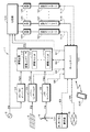
制御装置1は、ホームサーバ100、表示部101、蓄電装置102、切替部103、AC(Alternating Current)/DC(Direct Current)インバータ104、パワーコンディショナ105およびパワーコンディショナ106を含む構成とされる。表示部101は、例えば、ユーザの指やスタイラスペンにより操作が可能な、タッチパネルとして構成される。蓄電装置102は、蓄電コントローラ110と、16個の蓄電ユニット111(蓄電ユニット111a、蓄電ユニット111b、蓄電ユニット111c・・・蓄電ユニット111p)とを含む構成とされる。なお、蓄電ユニット111の個数は一例であり、16に限定されるものではない。
The
ホームサーバ100は、他の機器と通信を行うことができる。ホームサーバ100は、インターネット等のネットワーク115を介して、他の機器と通信を行うことができる。さらに、ホームサーバ100は、スマートフォンや携帯電話などの携帯端末200と近距離の無線通信を行うことができる。
The
切替部103に、複数の負荷120が接続される。それぞれの負荷120は、負荷120を制御する負荷コントローラ121を有する。ホームサーバ100および各負荷コントローラ121は、有線または無線のLAN(Local Area Network)に接続され、LANを介して、制御信号やデータのやり取りがなされる。負荷コントローラ121は、例えば、ホームサーバ100から供給される制御信号に応じて、負荷120の動作を制御する。なお、図1では、制御信号やデータの流れが点線の矢印により示されている。
A plurality of
電力の流れの一例について説明する。系統電力2から供給される電力P2(例えば、100V(ボルト)の交流電圧)が、切替部103に入力される。電力P2は、さらに、AC/DCインバータ104に入力される。AC/DCインバータ104により、交流の電力P2が直流の電力P20へ変換される。電力P20が蓄電装置102に入力される。
An example of power flow will be described. Electric power P <b> 2 (for example, AC voltage of 100 V (volt)) supplied from the
太陽光発電装置3からの直流の電力P3がパワーコンディショナ105に入力される。パワーコンディショナ105は、不安定な電力P3を安定な直流の電力P30に変換する。電力P30が蓄電装置102に入力される。
DC power P <b> 3 from the solar power generation device 3 is input to the
風力発電装置4からの直流の電力P4がパワーコンディショナ106に入力される。パワーコンディショナ106は、不安定な電力P4を安定な直流の電力P40に変換する。電力P40が蓄電装置102に入力される。
The DC power P4 from the
電力P20、電力P30および電力P40に基づいて蓄電ユニット111が充電される。例えば、電力P20に基づいて蓄電ユニット111aが充電される。電力P30に基づいて蓄電ユニット111bが充電される。電力P40に基づいて蓄電ユニット111cが充電される。そして、充電中ではない蓄電ユニット(例えば、蓄電ユニット111d)が放電し、蓄電ユニット111dから直流の電力P5が出力される。電力P5が切替部103に供給される。蓄電ユニット111に対する充電および蓄電ユニット111からの放電は、蓄電コントローラ110によって制御される。
The power storage unit 111 is charged based on the power P20, the power P30, and the power P40. For example, the
なお、夜間のときは、太陽光発電装置3からの電力P3は略0になる。無風状態のときは、風力発電装置4からの電力P4は略0になる。このため、電力P30や電力P40が蓄電装置102に常に供給されるとは限らない。
At night, the power P3 from the solar power generation device 3 is substantially zero. When there is no wind, the power P4 from the
次に、制御装置1の各部の詳細について、説明する。ホームサーバ100は、例えば、CPU(Central Processing Unit)により構成され、制御装置1の各部を制御する。ホームサーバ100は、切替部103に信号S1を供給する。信号S1は、例えば、切替部103におけるスイッチSWを切り替える制御信号である。
Next, the detail of each part of the
ホームサーバ100は、蓄電装置102の蓄電コントローラ110と通信を行い、信号S2をやり取りする。信号S2は、蓄電ユニット111の残容量の割合に関する情報、蓄電装置102に供給される電力の情報、ホームサーバ100から蓄電装置102に対して供給される制御信号などを総称したものである。
ホームサーバ100は、表示部101と信号S3のやり取りを行う。信号S3は、例えば、表示部101に所定の表示を行うための表示データや、表示部101を駆動するための駆動信号である。信号S3は、表示部101に対する操作に応じて生成される操作信号を含む。なお、ホームサーバ100から表示部101に対して供給される、表示部101の表示を制御するための制御信号を、制御信号S3aと適宜、称する。表示部101に対する操作に応じて生成され、表示部101からホームサーバ100に対して供給される操作信号を、操作信号S3bと適宜、称する。
ホームサーバ100に対して、パワーコンディショナ105から信号S4が供給される。信号S4は、例えば、太陽光発電装置3の発電量を示すデータである。信号S4は、例えば、所定の周期でもって、パワーコンディショナ105からホームサーバ100に供給される。
A signal S4 is supplied from the
ホームサーバ100に対して、パワーコンディショナ106から信号S5が供給される。信号S5は、例えば、風力発電装置4の発電量を示すデータである。信号S5は、例えば、所定の周期でもって、パワーコンディショナ106からホームサーバ100に供給される。
A signal S5 is supplied from the
ホームサーバ100は、ネットワーク115を介して他の機器と通信を行い、信号S6のやり取りをする。信号S6は、ホームサーバ100と他の機器との間でやり取りされるデータ等を総称したものである。
ホームサーバ100は、負荷120に接続される負荷コントローラ121と信号S10のやり取りをする。信号S10は、ホームサーバ100から負荷コントローラ121に対して供給される制御信号や、負荷120における現在の消費電力を示す情報を含む。
The
なお、図示は省略しているが、ホームサーバ100は、例えば、ROM(Read Only Memory)、RAM(Random Access Memory)などのメモリを有する。ROMには、ホームサーバ100が実行するプログラムが格納される。例えば、表示部101の表示を制御するための表示制御プログラムや、切替部103や負荷コントローラ121を制御するためのプログラムがROMに格納される。RAMは、例えば、ホームサーバ100がプログラムを実行する際のワークメモリとして使用される。各種のデータがRAMに記憶されてもよい。
Although not shown, the
表示部101は、LCD(Liquid Crystal Display)や有機EL(Electroluminescence)からなるモニタと、それらのモニタを駆動するためのドライバとを含む。ホームサーバ100から供給される制御信号S3aに応じてドライバが動作し、表示部101に所定の表示がなされる。表示部101は、例えば、片手または両手で操作可能な程度の大きさとされる。もちろん、表示部101の大きさは、適宜、変更することができる。
The
表示部101は、例えば、静電容量方式のタッチパネルとして構成される。抵抗膜方式や、光学方式などの他の方式のタッチパネルにより表示部101が構成されてもよい。表示部101に対して、スタイラスペンやユーザの指による触れる操作が可能とされる。表示部101に対する操作に応じて操作信号S3bが生成される。操作信号S3bがホームサーバ100に対して供給される。
The
蓄電装置102は、蓄電コントローラ110と、複数の蓄電ユニット111とを有する。蓄電装置102は、例えば、16個の蓄電ユニット111(蓄電ユニット111a、蓄電ユニット111b・・蓄電ユニット111p)を有する。個々の蓄電ユニットを区別する必要がない場合は、蓄電ユニット111と適宜、称する。蓄電ユニット111の個数は16に限定されず、適宜、増減できる。
The
蓄電コントローラ110は、各蓄電ユニット111を制御する。蓄電コントローラ110は、例えば、蓄電ユニット111の残容量の割合を取得し、取得した残容量の割合に関する情報を、ホームサーバ100に送信する。残容量の割合は、例えば、蓄電ユニット111の全体の容量に対する、全ての蓄電ユニット111の残容量の合計値の割合である。
The
蓄電コントローラ110は、蓄電ユニット111の充電を制御する。蓄電コントローラ110は、例えば、蓄電ユニット111ごとの残容量を取得し、残容量の最も少ない蓄電ユニット111を充電対象の蓄電ユニット111として決定する。充電回数が最小の蓄電ユニットを充電対象の蓄電ユニット111として決定してもよい。充電対象の蓄電ユニット111を決定するアルゴリズムは、適宜、変更できる。
The
蓄電コントローラ110は、充電対象の蓄電ユニット111を、例えば、電力P20を使用して充電する。電力P30や電力P40が供給される場合は、例えば、2番目に残容量が小さい蓄電ユニット111に対して、電力P30や電力P40を使用した充電が行われてもよい。蓄電コントローラ110により行われる充電の方式は、蓄電ユニット111の種類に応じて決定される。蓄電ユニット111が例えば、リチウムイオン二次電池である場合は、CCCV(Constant Voltage Constant Current)方式に基づく充電が行われる。
The
なお、蓄電ユニット111に対して電力P20や電力P30、電力P40に基づく充電ができるように、電力P20等を変換する処理(例えば、降圧する処理)が蓄電コントローラ110によって行われる。さらに、充電時における過充電の防止等の安全を確保する処理が蓄電コントローラ110によって行われてもよい。
Note that the
さらに、蓄電コントローラ110は、蓄電ユニット111の放電を制御する。蓄電コントローラ110は、例えば、蓄電ユニット111ごとの残容量を取得し、残容量の最も多い蓄電ユニット111を放電対象の蓄電ユニット111として決定する。放電回数が最小の蓄電ユニットを放電対象の蓄電ユニット111として決定してもよい。放電対象の蓄電ユニット111を決定するアルゴリズムは、適宜、変更できる。放電対象の蓄電ユニット111が放電する。放電による電力が適宜、蓄電コントローラ110により変換され、蓄電装置102から直流の電力P5が出力される。電力P5が切替部103に出力される。
Further, the
蓄電ユニット111は、リチウムイオン電池、オリビン型リン酸鉄リチウムイオン電池、鉛電池、NAS電池などである。これらが複数、接続されたものでもよい。例示した電池以外の電池や電気二重層キャパシタが使用されてもよい。蓄電コントローラ110は、蓄電ユニット111に対応した構成とされる。
The power storage unit 111 is a lithium ion battery, an olivine-type iron phosphate lithium ion battery, a lead battery, a NAS battery, or the like. A plurality of these may be connected. Batteries other than the exemplified batteries and electric double layer capacitors may be used. The
切替部103は、ホームサーバ100から供給される制御信号S1に応じて動作する。切替部103が動作することにより、負荷120に対する電力の供給が制御される。なお、切替部103の詳細については、後述する。
The
パワーコンディショナ105は、太陽光発電装置3の不安定な電力P3を安定な電力P30に変換する。パワーコンディショナ105は、太陽光発電装置3の太陽電池が発電する電力の変動に追従して、常に最大の電力点を追いかける制御(最大電力点追従制御(Maximum Power Point Tracking(MPPT))を行う。パワーコンディショナ105は、太陽光発電装置3の発電量を計測する計測計(図示は省略している)を有する。パワーコンディショナ105は、所定の周期(例えば、1秒)でもって太陽光発電装置3の発電量を計測し、太陽光発電装置3の発電量を示す信号S4をホームサーバ100に供給する。信号S4は、蓄電装置102に対する供給電力(電力P30)を示す情報でもよい。
The
パワーコンディショナ106は、風力発電装置4の不安定な電力P4を安定な電力P40に変換する。パワーコンディショナ106は、風力発電装置4の出力を最適化する制御などを行う。パワーコンディショナ106は、風力発電装置4の発電量を計測する計測計(図示は省略している)を有する。パワーコンディショナ106は、所定の周期(例えば、1秒)風力発電装置4の発電量を計測し、風力発電装置4の発電量を示す信号S5をホームサーバ100に供給する。信号S5は、蓄電装置102に対する供給電力(電力P40)を示す情報でもよい。
The
「1−2.切替部および負荷について」
切替部103の構成の一例および負荷について、図2を参照して説明する。切替部103には、系統電力2からの電力P2がラインL1を介して入力される。さらに、切替部103には、蓄電装置102からの電力P5がラインL2を介して入力される。
“1-2. Switching section and load”
An example of the configuration of the
切替部103は、複数の負荷120と接続される。複数の負荷120として、冷蔵庫120a、テレビジョン装置120b、LED(Light Emitting Diode)により構成される照明装置120cおよび空調装置120dが例示される。冷蔵庫120aは、スイッチSW1aを介してラインL1に接続され、スイッチSW1bを介してラインL2に接続される。テレビジョン装置120bは、スイッチSW2aを介してラインL1に接続され、スイッチSW2bを介してラインL2に接続される。
The
照明装置120cは、スイッチSW3aを介してラインL1に接続され、スイッチSW3bを介してラインL2に接続される。空調装置120dは、スイッチSW4aを介してラインL1に接続され、スイッチSW4bを介してラインL2に接続される。なお、個々のスイッチを区別する必要がない場合は、スイッチSWと適宜、称する。
The
スイッチSWは、FET(Field Effect Transistor)やIGBT(Insulated Gate Bipolar Transistor)などのスイッチング素子により構成される。ホームサーバ100から送信される制御信号S1により、個々のスイッチSWのオン/オフが制御される。例えば、電力P2を使用して冷蔵庫120aを動作させる場合は、スイッチSW1aがオンされ、スイッチSW1bがオフされる。電力P5を使用して冷蔵庫120aを動作させる場合は、スイッチSW1aがオフされ、スイッチSW1bがオンされる。
The switch SW is configured by a switching element such as an FET (Field Effect Transistor) or an IGBT (Insulated Gate Bipolar Transistor). On / off of each switch SW is controlled by the control signal S1 transmitted from the
負荷120は、負荷コントローラ121と接続される。冷蔵庫120aは、負荷コントローラ121aと接続される。テレビジョン装置120bは、負荷コントローラ121bと接続される。照明装置120cは、負荷コントローラ121cと接続される。空調装置120dは、負荷コントローラ121dと接続される。
The
負荷コントローラ121aは、冷蔵庫120aの動作を制御する。負荷コントローラ121aは、冷蔵庫120aに対する公知の制御を行う。例えば、負荷コントローラ121aは、冷蔵庫120aの庫内の温度を変更する制御を行う。冷蔵庫120aの庫内の温度をやや高めとし、冷蔵庫120aの消費電力を小さくする制御が負荷コントローラ121aにより行われる。冷蔵庫120aの庫内の温度を低くする制御が負荷コントローラ121aにより行われる。この制御の場合は、冷蔵庫120aの消費電力が大きくなる。負荷コントローラ121aによる制御は、例えば、ホームサーバ100から負荷コントローラ121aに供給される制御信号(適宜、制御信号S10aと称する)に応じて行われる。
The
負荷コントローラ121aは、センサ等を使用して、冷蔵庫120aの現在の消費電力を取得する。負荷コントローラ121aは、冷蔵庫120aの現在の消費電力を示す消費電力情報をホームサーバ100に供給する。負荷コントローラ121aは、さらに、インバータとして動作する。負荷コントローラ121aは、電力P2や電力P5を、冷蔵庫120aが対応するように、適宜、変換する。
The
負荷コントローラ121bは、テレビジョン装置120bの動作を制御する。負荷コントローラ121bは、テレビジョン装置120bに対する公知の制御を行う。例えば、負荷コントローラ121bは、テレビジョン装置120bの表示パネルの明るさを変更する制御を行う。テレビジョン装置120bの表示パネルの明るさを暗くし、テレビジョン装置120bの消費電力を小さくする制御が負荷コントローラ121bにより行われる。テレビジョン装置120bの表示パネルの明るさを通常の明るさより明るくする制御が負荷コントローラ121bにより行われる。この制御の場合は、テレビジョン装置120bの消費電力が大きくなる。負荷コントローラ121bによる制御は、例えば、ホームサーバ100から負荷コントローラ121bに供給される制御信号(適宜、制御信号S10bと称する)に応じて行われる。
The
負荷コントローラ121bは、センサ等を使用して、テレビジョン装置120bの現在の消費電力を取得する。負荷コントローラ121bは、テレビジョン装置120bの現在の消費電力を示す消費電力情報をホームサーバ100に供給する。負荷コントローラ121bは、さらに、電力P2や電力P5を、テレビジョン装置120bが対応するように、適宜、変換する。例えば、負荷コントローラ121bは、交流の電力P2を直流に変換する処理を行う。
The
負荷コントローラ121cは、照明装置120cの動作を制御する。負荷コントローラ121cは、照明装置120cに対する公知の制御を行う。例えば、負荷コントローラ121cは、照明装置120cの明るさを変更する制御を行う。照明装置120cの明るさを暗くし、照明装置120cの消費電力を小さくする制御が負荷コントローラ121cにより行われる。照明装置120cの明るさを明るくする制御が負荷コントローラ121cにより行われる。この制御の場合は、照明装置120cの消費電力が大きくなる。例えば、LEDに供給される電流を制御することにより、照明装置120cの明るさを変更できる。負荷コントローラ121cによる制御は、例えば、ホームサーバ100から負荷コントローラ121cに供給される制御信号(適宜、制御信号S10cと称する)に応じて行われる。
The
負荷コントローラ121cは、センサ等を使用して、照明装置120cの現在の消費電力を取得する。負荷コントローラ121cは、照明装置120cの現在の消費電力を示す消費電力情報をホームサーバ100に供給する。負荷コントローラ121cは、さらに、電力P2や電力P5を、照明装置120cが対応するように、適宜、変換する。
The
負荷コントローラ121dは、空調装置120dの動作を制御する。負荷コントローラ121dは、空調装置120dに対する公知の制御を行う。例えば、空調装置120dが冷房装置として使用される場合に、負荷コントローラ121dは、空調装置120dの設定温度を引き下げ、室温を低くするための制御を行う。この場合は、空調装置120dの消費電力は大きくなる。反対に、負荷コントローラ121dは、空調装置120dの設定温度を引き上げる制御を行う。この場合は、空調装置120dの消費電力は小さくなる。
The
負荷コントローラ121dによる制御は、例えば、ホームサーバ100から負荷コントローラ121dに供給される制御信号(適宜、制御信号S10dと称する)に応じて行われる。負荷コントローラ121dは、センサ等を使用して、空調装置120dの現在の消費電力を取得する。負荷コントローラ121dは、空調装置120dの現在の消費電力を示す消費電力情報をホームサーバ100に供給する。負荷コントローラ121dは、さらに、インバータとして動作し、電力P2や電力P5を、空調装置120dが対応するように、適宜、変換する。
The control by the
もちろん、例示した負荷120とは異なる負荷がラインL1およびラインL2に接続されてもよい。負荷120に対応する制御が、負荷120に接続される負荷コントローラ121によって行われる。
Of course, a load different from the illustrated
次に、制御装置1における、本開示に関連する動作の一例について説明する。ホームサーバ100は、所定の表示データと、表示部101に対する駆動信号とを含む制御信号S3aを表示部101に供給する。制御信号S3aに基づく表示が、表示部101に表示される。
Next, an example of an operation related to the present disclosure in the
表示部101に対して、例えば、ユーザの指(1本の指でもよく、複数の指でもよい)を使用した操作が行われる。操作に応じた操作信号S3bがホームサーバ100に供給される。ホームサーバ100は、操作信号S3bの内容を解析し、操作信号S3bに応じた制御を行う。例えば、ホームサーバ100は、操作信号S3bに応じて制御信号S3aを生成する。生成された制御信号S3aが表示部101に供給され、表示部101の表示が遷移する。
For example, an operation using the user's finger (a single finger or a plurality of fingers) may be performed on the
ホームサーバ100は、操作信号S3bに応じて、制御装置1の各部や負荷120の動作を制御する。例えば、ホームサーバ100は、操作信号S3bに応じて、切替部103のスイッチSWのオン/オフを制御する。例えば、ホームサーバ100は、操作信号S3bに応じて、負荷コントローラ121に対して制御信号S10を送出し、負荷コントローラ121に接続される負荷120の動作を制御する。このように、ホームサーバ100は、表示部101に対する操作に応じて、表示部101の表示内容を適宜、変更する処理や、制御装置1の各部や負荷120の動作を制御する処理を行う。以下、具体例を挙げて説明する。
The
「1−3.第1の具体例」
第1の具体例について説明する。第1の具体例における初期状態では、切替部103のスイッチSW2aおよびスイッチSW2bがオフされているものとして説明する。
“1-3. First Specific Example”
A first specific example will be described. In the initial state in the first specific example, it is assumed that the switch SW2a and the switch SW2b of the
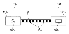
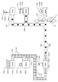
図3は、表示部101に表示されるマークの一例を示す。図3に示すように、第1のマークの一例であるマーク130と、第2のマークの一例であるマーク131とが、表示部101に離隔して表示される。マーク130およびマーク131は、例えば、制御装置1に対してなされる表示の指示に応じて、表示される。マーク130は、電力の供給側(例えば、系統電力2)に対応するマークであり、マーク131は、電力の消費側(例えば、テレビジョン装置120b)に対応するマークである。
FIG. 3 shows an example of marks displayed on the
マーク130は、例えば、矩形のマーク130aと、マーク130aの、図面に向かって右側に表示され、接続端子を模したマーク130bと、マーク130aの内部に表示されるマーク130cとを含む。マーク130cは、例えば、系統電力2を模したマークである交流の電圧源のマークである。
The
マーク131は、例えば、矩形のマーク131aと、マーク131aの左側に表示され、接続端子を模したマーク131bと、マーク131aの内部に表示されるマーク131cとを含む。マーク131cは、マーク131に対応する装置であるテレビジョン装置を模したマークである。
The
マーク130およびマーク131の形状は、例示した形状に限定されることなく、適宜、変更できる。例えば、マーク130が円形でもよい。マーク130においてマーク130bがなくてもよい。マーク130およびマーク131は、例えば、後述する操作が可能となるように、表示部101における適切な位置に表示される。
The shapes of the
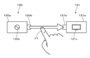
図4は、第1の具体例における表示部101に対する操作を示す。ユーザの指(例えば、人差し指)F1を使用して、マーク130とマーク131とを結びつけるような操作が表示部101に対して行われる。例えば、指F1がマーク130bもしくはその近傍を押下する。指F1により表示部101を押下したまま、指F1をマーク131bにスライドさせる。図4に例示する操作を、ドラッグ操作と、適宜、称する。
FIG. 4 shows operations on the
図5は、ドラッグ操作がなされた後の表示部101の表示の一例を示す。ドラッグ操作がなされた後とは、例えば、マーク131bまでスライドさせた指F1を表示部101から離したタイミングである。ドラッグ操作に応じて、マーク130とマーク131とを連結する連結路135が表示される。連結路135におけるマーク130付近で表示単位136が表示される。表示単位136は、連結路135をマーク131に向かって、所定の移動速度で移動する。マーク131付近まで達した表示単位136は消去される。なお、図示が煩雑となるのを防止するため、一部の表示単位に対してのみ、参照符号136を付している。
FIG. 5 shows an example of display on the
すなわち、連結路135を、複数の表示単位136がマーク130からマーク131に向かうように移動する。マーク131に対応する装置により使用される現在の電力(消費電力)に応じて、表示単位136の移動速度が変化する。例えば、マーク131に対応する装置の現在の消費電力が大きくなるほど表示単位136の移動速度が大きくなり、マーク131に対応する装置の現在の消費電力が小さくなるほど表示単位136の移動速度が小さくなる。
That is, the plurality of
マーク131が消費するエネルギー(電力)の量と表示単位136の表示数が対応している。例えば、マーク131に対応する装置の現在の消費電力が大きくなるほど表示単位136の表示数が増加し、マーク131に対応する装置の現在の消費電力が小さくなるほど表示単位136の表示数が減少する。もちろん、表示単位136の移動速度や、表示単位136の表示数に異なる意味づけがなされてよい。移動速度や表示数のいずれか一方のみを変化させるようにしてもよい。表示単位136の大きさや形状を変化させるようにしてもよい。表示単位136が移動する表示により、電力の流れを示すことができる。表示単位136は、例えば、矩形のマークとされる。円形など他の形状でもよく、さらに、赤色や青色などの任意の色で着色されてもよい。
The amount of energy (electric power) consumed by the
なお、指F1をスライドさせる操作に応じて、連結路135が徐々に形成されるような表示がなされるようにしてもよい。さらに、ドラッグ操作が、指F1をマーク131からマーク130に向かってスライドさせることによりなされてもよい。この場合でも、電力の流れに対応して、表示単位136は、マーク130からマーク131に向かって、連結路135を移動する。
Note that a display may be made such that the
図6は、第1の具体例における処理の流れの一例を示すフローチャートである。図6に示す処理は、例えば、ホームサーバ100の制御に基づいて実行される。
FIG. 6 is a flowchart showing an example of the flow of processing in the first specific example. The process illustrated in FIG. 6 is executed based on the control of the
ステップST1では、電力の供給側のマーク(例えば、マーク130)と、電力の消費側のマーク(マーク131)とが、表示部101に表示中であるか否かが判断される。マーク130およびマーク131が表示されていない場合は、処理がステップST1に戻り、ステップST1の判断処理が繰り返される。マーク130およびマーク131が表示部101に表示中である場合は、処理がステップST2に進む。
In step ST <b> 1, it is determined whether a power supply side mark (for example, mark 130) and a power consumption side mark (mark 131) are being displayed on the
ステップST2では、ドラッグ操作がなされたか否かが判断される。すなわち、ドラッグ操作に対応する操作信号S3bが表示部101から供給されたか否かが、ホームサーバ100により判断される。ドラッグ操作がなされない場合は処理がステップST2に戻り、ステップST2の判断処理が繰り返される。ドラッグ操作がなされる場合は、処理がステップST3に進む。
In step ST2, it is determined whether or not a drag operation has been performed. That is, the
ステップST3では、ドラッグ操作に応じて、連結路135が表示部101に表示される。そして、処理がステップST4に進む。
In step ST3, the
ステップST4では、ドラッグ操作に応じてホームサーバ100が所定の制御を行う。表示部101の表示内容に対応する制御がホームサーバ100により実行される。例えば、ホームサーバ100は、切替部103にスイッチSW2aをオンするための制御信号S1を供給する。制御信号S1に応じてスイッチSW2aがオンする。テレビジョン装置120bに対して電力P2が供給され、テレビジョン装置120bがスタンバイ状態となる。なお、スイッチSW2bはオフされたままである。
In step ST4, the
ドラッグ操作に応じてホームサーバ100が行う制御の内容は、テレビジョン装置120bに対する電力P2の供給に限られない。ユーザが知覚できる制御がホームサーバ100により行われてもよい。例えば、スイッチSW2aがオンされることにより、電力P2がテレビジョン装置120bに供給される。ホームサーバ100は、負荷コントローラ121bに対してテレビジョン装置120bを起動するための制御信号S10bを供給する。制御信号S10bに応じて、負荷コントローラ121bは、テレビジョン装置120bを起動する。このように、ユーザが知覚できる制御が行われる方が、ユーザインターフェースとしては好ましい。ステップST4の処理に続いて、処理がステップST5に進む。
The content of the control performed by the
ステップST5では、マーク130からマーク131に向かって連結路135を移動する表示単位136が表示される。例えば、テレビジョン装置120bで使用される電力に応じて、表示単位136の個数や移動速度が設定される。設定された個数や移動速度に基づいて、表示単位136が表示される。
In step ST5, a
図7に示すように、電力の消費側のマークが複数あってもよい。例えば、照明装置120cに対応するマーク138が表示されてもよい。マーク138は、マーク131と同様に、矩形のマーク138aと、接続端子を模したマーク138bと、照明装置120cを模したマーク138cとを含む。連結路135が表示される場合は、マーク138bは表示されない。
As shown in FIG. 7, there may be a plurality of marks on the power consumption side. For example, a
例えば、マーク130とマーク138とを結びつけるドラッグ操作に応じて、連結路135が分岐する。連結路135の分岐の先が、マーク138に接続される。連結路135の途中の箇所を始点とし、マーク138の近傍の箇所を終点とするドラッグ操作を行うことにより、マーク130とマーク138とを連結する連結路が表示されてもよい。表示された連結路を表示単位136が移動する。ドラッグ操作に応じて、照明装置120cが点灯する制御がホームサーバ100によって行われてもよい。マーク130とマーク138を連結する、連結路135とは独立した連結路が表示されるようにしてもよい。分岐したそれぞれの連結路を移動する表示単位の個数を、分岐前の連結路を移動する表示単位の個数の略半分としてもよい。
For example, the
以上、説明したように、例えば、ドラッグ操作を行うことにより、電力を供給する側の装置から電力を消費する側の装置に対して、所定物の一例である電力が供給される。なお、所定物は、必ずしも有体物や人が知覚できるものに限られない。 As described above, for example, by performing a drag operation, power that is an example of a predetermined object is supplied from a device that supplies power to a device that consumes power. Note that the predetermined object is not necessarily limited to a tangible object or a person that can be perceived.
「1−4.第2の具体例」
次に、第2の具体例について説明する。表示部101には、例えば、図5に例示したように、マーク130と、マーク131と、マーク130およびマーク131を連結する連結路135と、連結路135を移動する複数の表示単位136が表示されているものとして説明する。
“1-4. Second Specific Example”
Next, a second specific example will be described. For example, as illustrated in FIG. 5, the
図8は、第2の具体例における表示部101に対する操作を示す。例えば、指F1を使用して、連結路135を遮断するように表示部101をなぞる操作が行われる。以下、この操作を、適宜、カット操作またはシングルカット操作と称する。カット操作に応じて、連結路135および連結路135を移動する表示単位136が消去され、非表示となる。表示部101には、マーク130およびマーク131が離隔して表示される。例えば、図3と同様にして、マーク130およびマーク131が表示部101に表示される。
FIG. 8 shows operations on the
図9は、第2の具体例における処理の流れの一例を示すフローチャートである。図9に示す処理は、例えば、ホームサーバ100の制御に基づいて実行される。
FIG. 9 is a flowchart illustrating an example of the flow of processing in the second specific example. The process shown in FIG. 9 is executed based on the control of the
ステップST11では、電力の供給側のマーク(例えば、マーク130)と、電力の消費側のマーク(例えば、マーク131)と、連結路135と、連結路135を移動する複数の表示単位136(適宜、マーク130等と略称する)が表示部101に表示中であるか否が判断される。マーク130等が表示部101に表示されていない場合は、処理がステップST11に戻り、ステップST11の判断処理が繰り返される。マーク130等が表示部101に表示中である場合は、処理がステップST12に進む。
In step ST11, a power supply side mark (for example, mark 130), a power consumption side mark (for example, mark 131), a
ステップST12では、カット操作がなされたか否かが判断される。ホームサーバ100は、表示部101における連結路135の表示位置を保持している。このため、操作信号S3bにより示される指F1による操作箇所と、連結路135の表示位置とに基づいて、カット操作がなされたか否かをホームサーバ100が判断できる。カット操作がなされない場合は、処理がステップST12に戻り、ステップST12の判断処理が繰り返される。カット操作がなされると、処理がステップST13に進む。
In step ST12, it is determined whether or not a cutting operation has been performed. The
ステップST13では、カット操作に応じてホームサーバ100が所定の制御を行う。表示部101には、ホームサーバ100は、負荷コントローラ121bに対してテレビジョン装置120bをオフするための制御信号S10bを供給する。制御信号S10bに応じて、負荷コントローラ121bはテレビジョン装置120bをオフする。テレビジョン装置120bは、例えば、スタンバイ状態に遷移する。そして、処理がステップST14に進む。
In step ST13, the
ステップST14では、テレビジョン装置120bに対する電力の供給が停止されたことに対応する表示がなされる。例えば、連結路135および表示単位136を表示部101から消去する処理が行われる。
In step ST14, a display corresponding to the stop of the power supply to the
なお、複数の指を使用してカット操作がなされてもよい。例えば、図10に示すように、2本の指(指F1および指(中指)F2)を使用したカット操作がなされてもよい。2本の指を使用したカット操作を、適宜、ダブルカット操作と称する。 The cutting operation may be performed using a plurality of fingers. For example, as shown in FIG. 10, a cutting operation using two fingers (finger F1 and finger (middle finger) F2) may be performed. A cutting operation using two fingers is appropriately referred to as a double cutting operation.
シングルカット操作およびダブルカット操作のそれぞれに応じて、異なる制御がホームサーバ100によって行われるようにしてもよい。例えば、シングルカット操作に応じて、テレビジョン装置120bがオフされ、スタンバイ状態とされる制御が行われる。ダブルカット操作に応じて、テレビジョン装置120bがオフされ、かつ、スイッチSW2aがオフされる制御が行われてもよい。スイッチSW2aがオフされるため、待機電力をなくすことができる。
Different controls may be performed by the
表示部101上で電力の流れを止める操作は、カット操作に限られない。例えば、図11に示すような、指F1により連結路135の所定箇所を所定時間、押下し、表示単位136の移動を妨げる操作でもよい。この操作を、適宜、ホールド操作を称する。ホールド操作に応じて表示単位136の移動が妨げられ、表示単位が停止する。すなわち、あたかもテレビジョン装置に対する電力の供給が停止した様子が表示される。ホールド操作に応じて、テレビジョン装置120bがオフされる。スイッチSW2aをオフする制御が行われてもよい。
The operation for stopping the flow of power on the
指F1が表示部101から離され、ホールド操作が解除されると、表示単位136が再び移動を開始する。ホールド操作の解除に応じて、テレビジョン装置120bがオンされる制御がホームサーバ100により行われてもよい。
When the finger F1 is released from the
「1−5.第3の具体例」
次に、第3の具体例について説明する。表示部101には、例えば、マーク130と、照明装置120cに対応するマーク138、マーク130およびマーク138を連結する連結路135と、連結路135を移動する複数の表示単位136が表示されているものとして説明する。
"1-5. Third specific example"
Next, a third specific example will be described. On the
図12は、第3の具体例における表示部101に対する操作を示す。例えば、指F1および指(親指)F3により表示部101の所定位置を押下し、連結路135の幅を狭めるように2本の指を近づける操作が行われる。この操作を、ピンチイン操作と、適宜、称する。指F1および指F3により押下される表示部101の所定位置は、連結路135が表示される表示領域や、連結路135の周辺における予め設定された領域など、表示部101の大きさ等に応じて適切に設定される。
FIG. 12 shows operations on the
図13は、ピンチイン操作がなされた場合の表示の一例を示す。ピンチイン操作に応じて、例えば、表示単位136の移動速度が小さくなる。連結路135の幅の大きさを小さくしてもよい。表示単位136の移動速度を変更せずに、表示単位136の表示数(表示間隔)を少なくしてもよい。
FIG. 13 shows an example of a display when a pinch-in operation is performed. In accordance with the pinch-in operation, for example, the moving speed of the
図14は、第3の具体例における処理の流れの一例を示すフローチャートである。図14に示す処理は、例えば、ホームサーバ100の制御に基づいて実行される。
FIG. 14 is a flowchart illustrating an example of the flow of processing in the third specific example. The process illustrated in FIG. 14 is executed based on the control of the
ステップST21では、電力の供給側のマーク(例えば、マーク130)と、電力の消費側のマーク(例えば、マーク138)と、連結路135と、連結路135を移動する複数の表示単位136(適宜、マーク130等と略称する)が表示部101に表示中であるか否が判断される。マーク130等が表示部101に表示されていない場合は、処理がステップST21に戻り、ステップST21の判断処理が繰り返される。マーク130等が表示部101に表示中である場合は、処理がステップST22に進む。
In step ST21, a power supply side mark (for example, mark 130), a power consumption side mark (for example, mark 138), a
ステップST22では、ピンチイン操作がなされたか否かが判断される。ピンチイン操作がなされたか否かの判断は、公知の方法によって判断される。ピンチイン操作がなされない場合は、処理がステップST22に戻り、ステップST22の判断処理が繰り返される。ピンチイン操作がなされると、処理がステップST23に進む。 In step ST22, it is determined whether a pinch-in operation has been performed. Whether or not a pinch-in operation has been performed is determined by a known method. When the pinch-in operation is not performed, the process returns to step ST22, and the determination process of step ST22 is repeated. When a pinch-in operation is performed, the process proceeds to step ST23.
ステップST23では、ピンチイン操作に応じてホームサーバ100が所定の制御を行う。ホームサーバ100は、例えば、照明装置120cの明るさを暗くする制御を行う。この制御により照明装置120cの明るさが暗くなり、照明装置120cの消費電力が小さくなる。
In step ST23, the
ホームサーバ100は、負荷コントローラ121cに対して、照明装置120cの明るさを暗くするための制御信号S10cを供給する。制御信号S10cに応じて、負荷コントローラ121cは照明装置120cの明るさ(照度)を所定の割合でもって小さくする。そして、処理がステップST24に進む。
The
ステップST24では、消費電力が減少したことに対応する表示がなされる。例えば、表示単位136の移動速度が小さくされる。なお、消費電力の増減に応じて、表示単位136の移動速度をどの程度、変更するかは、表示部101の大きさ等に応じて、適宜、設定できる。
In step ST24, a display corresponding to the reduction in power consumption is made. For example, the moving speed of the
一度、ピンチイン操作がなされた後に、再度、ピンチイン操作がなされた場合には、照明装置120cの明るさをさらに暗くする制御が行われてもよい。電力を消費する側の装置は照明装置120cに限られない。例えば、電力を消費する側の装置が、テレビジョン装置120bの場合は、ピンチイン操作に応じて、テレビジョン装置120bの表示パネルの明るさを暗くする制御が、ホームサーバ100および負荷コントローラ121bにより行われる。テレビジョン装置120bの表示パネルの明るさを暗くする制御により、テレビジョン装置120bの消費電力が小さくなる。表示単位136の移動速度がさらに小さくされる。
When the pinch-in operation is performed again after the pinch-in operation is performed once, the brightness of the
例えば、電力を消費する側の装置が、冷房装置として使用される空調装置120dの場合は、空調装置120dの設定温度を上げる制御がホームサーバ100および負荷コントローラ121dにより行われる。この制御により、空調装置120dの消費電力が小さくなる。空調装置120dが暖房装置として使用される場合は、空調装置120dの設定温度を下げる制御がホームサーバ100および負荷コントローラ121dにより行われる。この制御により、空調装置120dの消費電力が小さくなる。
For example, when the device that consumes power is the
「1−6.第4の具体例」
次に、第4の具体例について説明する。表示部101には、例えば、マーク130と、照明装置120cに対応するマーク138、マーク130およびマーク138を連結する連結路135と、連結路135を移動する複数の表示単位136が表示されているものとして説明する。
"1-6. Fourth example"
Next, a fourth specific example will be described. On the
図15は、第4の具体例における表示部101に対する操作を示す。例えば、指F1および指F3により表示部101の所定位置を押下し、連結路135の幅を広げるように2本の指を離す操作が行われる。この操作を、ピンチアウト操作と、適宜、称する。指F1および指F3により押下される表示部101の所定位置は、連結路135が表示される表示領域や、連結路135の周辺における予め設定された領域など、表示部101の大きさ等に応じて適切に設定される。
FIG. 15 shows operations on the
図16は、ピンチアウト操作がなされた場合の表示の一例を示す。ピンチアウト操作に応じて、例えば、連結路135の幅が大きくなり、表示単位136の移動速度が大きくなる。さらに、移動する表示単位136の個数が増加する。連結路135の幅を変更せずに、表示単位136の移動速度が大きくしたり、移動する表示単位136の個数を増加させるようにしてもよい。
FIG. 16 shows an example of a display when a pinch-out operation is performed. In accordance with the pinch-out operation, for example, the width of the
図17は、第4の具体例における処理の流れの一例を示すフローチャートである。図17に示す処理は、例えば、ホームサーバ100の制御に基づいて実行される。
FIG. 17 is a flowchart illustrating an example of a processing flow in the fourth specific example. The process illustrated in FIG. 17 is executed based on the control of the
ステップST31では、電力の供給側のマーク(例えば、マーク130)と、電力の消費側のマーク(例えば、マーク138)と、連結路135と、連結路135を移動する複数の表示単位136(適宜、マーク130等と略称する)が表示部101に表示中であるか否が判断される。マーク130等が表示部101に表示されていない場合は、処理がステップST31に戻り、ステップST31の判断処理が繰り返される。マーク130等が表示部101に表示中である場合は、処理がステップST32に進む。
In step ST31, a power supply side mark (for example, mark 130), a power consumption side mark (for example, mark 138), a
ステップST32では、ピンチアウト操作がなされたか否かが判断される。ピンチアウト操作がなされたか否かの判断は、公知の方法によって判断される。ピンチアウト操作がなされない場合は、処理がステップST32に戻り、ステップST32の判断処理が繰り返される。ピンチアウト操作がなされると、処理がステップST33に進む。 In step ST32, it is determined whether a pinch-out operation has been performed. Whether or not a pinch-out operation has been performed is determined by a known method. When the pinch out operation is not performed, the process returns to step ST32, and the determination process of step ST32 is repeated. When a pinch out operation is performed, the process proceeds to step ST33.
ステップST33では、ピンチアウト操作に応じてホームサーバ100が所定の制御を行う。ホームサーバ100は、例えば、照明装置120cの明るさを明るくする制御を行う。この制御により照明装置120cの明るさが明るくなり、照明装置120cの消費電力が大きくなる。
In step ST33, the
ホームサーバ100は、負荷コントローラ121cに対して、照明装置120cの明るさを明るくするための制御信号S10cを供給する。制御信号S10cに応じて、負荷コントローラ121cは照明装置120cの明るさ(照度)を所定の割合でもって明るくする。そして、処理がステップST34に進む。
The
ステップST34では、消費電力が増加したことに対応する表示がなされる。例えば、連結路135の幅を大きくし、表示単位136の移動速度が大きくされる。さらに、移動する表示単位136の表示数が増加される。
In step ST34, a display corresponding to the increase in power consumption is made. For example, the width of the connecting
一度、ピンチアウト操作がなされた後に、再度、ピンチアウト操作がなされた場合には、照明装置120cの明るさをさらに明るくする制御が行われてもよい。電力を消費する側の装置は照明装置120cに限られない。例えば、電力を消費する側の装置が、テレビジョン装置120bの場合は、ピンチアウト操作に応じて、テレビジョン装置120bの表示パネルの明るさを明るくする制御が、ホームサーバ100および負荷コントローラ121bにより行われる。テレビジョン装置120bの表示パネルの明るさを明るくする制御により、テレビジョン装置120bの消費電力が小さくなる。表示単位136の移動速度がさらに大きくされ、表示単位136の表示数がさらに増加される。
When the pinch-out operation is performed again after the pinch-out operation is once performed, control for further increasing the brightness of the
例えば、電力を消費する側の機器が、冷房装置として使用される空調装置120dの場合は、空調装置120dの設定温度を下げる制御がホームサーバ100および負荷コントローラ121dにより行われる。この制御により、空調装置120dの消費電力が大きくなる。空調装置120dが暖房装置として使用される場合は、空調装置120dの設定温度を上げる制御がホームサーバ100および負荷コントローラ121dにより行われる。この制御により、空調装置120dの消費電力が大きくなる。
For example, when the device that consumes power is the
「1−7.第5の具体例」
次に、第5の具体例について説明する。第5以下の具体例では、マークの表示態様が上述したマーク130等と異なる。
“1-7. Fifth Specific Example”
Next, a fifth specific example will be described. In the fifth and following specific examples, the display mode of the mark is different from the
図18Aは、蓄電装置102に対応するマーク150の一例を示す。マーク150は、例えば、矩形とされるマーク150aを含む。マーク150aの上部に、蓄電装置102を模した電池のマーク150bが表示される。蓄電装置102は、電力を供給する装置でもあり、電力が供給される装置でもある。したがって、2つの接続端子を模したマーク150cおよびマーク150dが表示される。マーク150cおよびマーク150dは、例えば、マーク150aの両端に表示される。
FIG. 18A illustrates an example of a
マーク150aの内部には、例えば、蓄電装置102の残容量の割合(例えば、60%)が表示される。ホームサーバ100は、蓄電装置102の蓄電コントローラ110との通信とにより、蓄電装置102の残容量の割合に関する情報を取得できる。ホームサーバ100は、取得した情報に基づいて、蓄電装置102の残容量の割合を表示部101に表示する制御を行う。
For example, the ratio (for example, 60%) of the remaining capacity of the
マーク150cの内部には、例えば、蓄電装置102に対して供給される電力(電力P2、電力P3および電力P4)の合計値(例えば、200W(ワット))が表示される。電力P2の値は、ラインL1に接続される負荷の台数や、ユーザと電力会社との間の契約等に応じて設定される値であり、この値は、例えば、ホームサーバ100が有するRAM等に保持される。
For example, a total value (for example, 200 W (watts)) of power (power P2, power P3, and power P4) supplied to the
ホームサーバ100は、パワーコンディショナ105との間の通信により、信号S4により示される電力P3の値を取得する。ホームサーバ100は、パワーコンディショナ106との間の通信により、信号S5により示される電力P4の値を取得する。ホームサーバ100は、これらの電力に関する情報に基づいて、マーク150cの内部に表示される数値の表示を制御する。
マーク150dには、蓄電装置102に接続される負荷120の消費電力の合計値(例えば、80W)が表示される。ホームサーバ100は、負荷コントローラ121との間の通信により、負荷120の現在の消費電力を取得する。ホームサーバ100は、負荷120の現在の消費電力の合計値を求め、合計値をマーク150dの内部に表示する制御を行う。なお、マーク150a、マーク150cおよびマーク150dの内部に表示される数値は変動しうる。
The total power consumption (for example, 80 W) of the
図18Bは、テレビジョン装置120bに対応するマーク151の一例を示す。マーク151は、例えば、矩形のマーク151aを含む。マーク151aの上部にテレビジョン装置120bを模したマーク151bが表示される。テレビジョン装置120bは、電力が供給される装置である。したがって、接続端子を模したマーク151cが1つ表示される。マーク151cは、例えば、マーク151aの左側に表示される。
FIG. 18B shows an example of a
マーク151aの内部には、マーク151が対応する装置の消費電力が表示される。例えば、テレビジョン装置120bの現在の消費電力(例えば、230W)が表示される。ホームサーバ100は、負荷コントローラ121との間の通信により負荷120の現在の消費電力を取得する。ホームサーバ100は、取得した消費電力の情報をマーク151aの内部に表示する制御を行う。なお、テレビジョン装置120bの動作の状況や設定に応じて、テレビジョン装置120bの消費電力は変動する。このため、マーク151aの内部に表示される数値も変動しうる。
The power consumption of the device corresponding to the
近年の電子機器には、電子機器における消費電力を小さくするモード(節電モード)が設定できるものが多い。節電モードが設定された場合には、マーク151aの内部の数値は、230Wに比して小さくなる。
Many electronic devices in recent years can set a mode (power saving mode) for reducing power consumption in the electronic device. When the power saving mode is set, the numerical value inside the
図19は、第5の具体例における表示部101の表示の一例を示す。表示部101には、太陽光発電装置3に対応するマーク152が表示される。マーク152は、矩形のマーク152aと、マーク152aの上部に表示され、太陽光パネルを模したマーク152bとを含む。マーク152aの内部には、太陽光発電装置3からの現在の電力の供給量(例えば、452W)が表示される。
FIG. 19 shows an example of display on the
表示部101には、系統電力2に対応するマーク153が表示される。マーク153は、矩形のマーク153aと、マーク153aの上部に表示され、系統電力2(交流の電圧源)を模したマーク153bとを含む。マーク153aの内部には、系統電力2からの現在の電力の供給量(例えば、420W)が表示される。なお、系統電力2から供給される電力は、蓄電装置102および切替部103のそれぞれに供給することができる。このため、マーク153aの右側からは、独立した2本の連結路(後述する連結路160および連結路165)が延在する。
A
表示部101には、蓄電装置102に対応するマーク150が表示される。表示部101には、テレビジョン装置120bに対応するマーク151が表示される。マーク150およびマーク151については、上述したので、重複した説明を省略する。
A
表示部101には、冷蔵庫120aに対応するマーク155が表示される。マーク155は、矩形のマーク155aと、マーク155aの上部に表示され、冷蔵庫120aを模したマーク155bとを含む。マーク155aの内部には、冷蔵庫120aの現在の消費電力(例えば、40W)が表示される。
The
表示部101には、照明装置120cに対応するマーク156が表示される。マーク156は、矩形のマーク156aと、マーク156aの上部に表示され、照明装置120cを模したマーク156bとを含む。マーク156aの内部には、照明装置120cの現在の消費電力(例えば、30W)が表示される。
On the
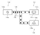
表示部101には、複数の連結路が表示される。例えば、マーク152およびマーク153と、マーク150とを連結する連結路160が表示される。マーク152からマーク150に向かって複数の表示単位161が連結路160を移動する。さらに、マーク153からマーク150に向かって複数の表示単位161が連結路160を移動する。
The
マーク153とマーク155とを連結する連結路165が表示される。マーク153からマーク155に向かって複数の表示単位166が連結路165を移動する。
A
マーク150とマーク151およびマーク156とを連結する連結路168が表示される。連結路168は途中から分岐し、マーク151およびマーク156のそれぞれと接続する。マーク150から、マーク151およびマーク156のそれぞれに向かって、表示単位169が連結路168を移動する。なお、蓄電装置102に対応するマーク150に向かって移動する表示単位161と、負荷120に対応するマーク(例えば、マーク151、マーク155およびマーク156)に向かって移動する表示単位169とが異なる色で着色されて表示されてもよい。
A
図19に例示する表示により、太陽光発電装置3および系統電力2から蓄電装置102に対して電力が供給されている様子が表示される。さらに、系統電力2から供給される電力が冷蔵庫120aに供給されている様子が表示される。さらに、蓄電装置102から供給される電力P5が、テレビジョン装置120bおよび照明装置120cに供給されている様子が表示される。
With the display illustrated in FIG. 19, a state in which power is supplied from the solar power generation device 3 and the
なお、表示部101における各マークの表示位置は適宜、変更できるが、電力の流れを考慮して、表示部101の一方(例えば、左側)に電力を供給する側のマークが近接して表示され、表示部101の他方(例えば、右側)に電力を消費する側のマークが近接して表示されることが好ましい。
Note that the display position of each mark on the
なお、風力発電装置4に対応するマークが表示されていない。これは、例えば、無風であり、風力発電装置4の発電量が小さいことを意味する。このように、一定以上の発電量がない発電装置を表示部101に表示しないようにしてもよい。風力発電装置4に対応するマークを、0Wの数値とともに表示してもよい。
In addition, the mark corresponding to the
図19の表示に対応したスイッチSWのオンまたはオフの状態について説明する。表示部101には、系統電力2に対応するマーク153から冷蔵庫120aに対応するマーク155に向かって電力が流れている様子が表示されている。この表示に対応するように、スイッチSWがオン/オフされる。すなわち、切替部103におけるスイッチSW1aがオンされ、スイッチSW1bがオフされる。
The on / off state of the switch SW corresponding to the display of FIG. 19 will be described. The
表示部101には、蓄電装置102に対応するマーク150からテレビジョン装置120bに対応するマーク151および照明装置120cに対応するマーク156に向かって電力が流れている様子が表示されている。切替部103におけるスイッチSW2aがオフされ、スイッチSW2bがオンされる。さらに、切替部103におけるスイッチSW3aがオフされ、スイッチSW3bがオンされる。なお、表示部101には、空調装置120dに対する電力の流れが表示されていない。このため、スイッチSW4aおよびスイッチSW4bはオフされる。
The
太陽光発電装置3から、例えば、452Wの電力が蓄電装置102に供給される。これに対応して、マーク152aの内部に452Wが表示される。系統電力2からは、例えば、420Wの電力が供給され、そのうち、40Wの電力が冷蔵庫120aにより消費され、残りの380Wが蓄電装置102に供給される。これに対応して、マーク153aの内部には420Wが表示され、マーク155aの内部に40Wが表示される。マーク150cの内部に、電力の供給量の合計値(452+380)である832Wが表示される。マーク150aの内部に、蓄電装置102の残容量の合計の割合(例えば、59%)が表示される。
For example, 452 W of power is supplied from the solar power generation device 3 to the
テレビジョン装置120bでは、例えば、230Wの電力が消費され、照明装置120cでは、例えば、30Wの電力が消費される。これに対応して、マーク151aの内部に230Wが表示され、マーク156aの内部に30Wが表示される。マーク150dの内部に、テレビジョン装置120bの消費電力および照明装置120cの消費電力の合計値(230+30)である260Wが表示される。
The
ところで、図19の表示からは、負荷120における消費電力の合計(300W)に比して太陽光発電装置3から供給される電力(452W)が大きいことがわかる。さらに、蓄電装置102の残容量も少なくない。このような場合には、系統電力2から供給される電力を使用せずに、太陽光発電装置3から供給される電力、言い換えれば、蓄電装置102から供給される電力を使用することが、費用および省エネルギーの観点から好ましい。第5の具体例では、表示部101に対する操作に応じて、電力の供給源を切り替えることができる。
By the way, it can be seen from the display of FIG. 19 that the power (452 W) supplied from the photovoltaic power generation device 3 is larger than the total power consumption (300 W) in the
図20は、第5の具体例における操作を示す。第5の具体例では、複数の操作が連続的になされる。例えば、始めに、連結路165に対する(シングル)カット操作がなされる。次に、マーク150の例えば、マーク150d付近の箇所と、マーク155の例えば、マーク155aとを結びつけるドラッグ操作がなされる。
FIG. 20 shows operations in the fifth specific example. In the fifth specific example, a plurality of operations are continuously performed. For example, first, a (single) cut operation on the
図21は、操作後の表示の一例を示す。カット操作に応じて、連結路165および連結路165を移動する表示単位166が表示部101から消去され、非表示とされる。なお、連結路165が非表示されることに応じて、マーク153には、接続端子を模したマーク153cを表示しているが、マーク153cは表示されなくてもよい。
FIG. 21 shows an example of the display after the operation. In response to the cutting operation, the
ドラッグ操作に応じて、マーク150とマーク155とを連結する連結路が表示される。例えば、連結路168が延伸され、連結路168がマーク155aに接続された表示がなされる。そして、表示単位169が、さらに、マーク155に向かうように移動する。
A connection path that connects the
系統電力2から供給される電力を使用する負荷120がなくなる。なお、マーク153とマーク150とが接続されていることから、系統電力2から蓄電装置102に対しては、例えば、380Wの電力の供給が継続する。これに対応して、マーク153aの内部に380Wが表示される。これに対応して、マーク150cの内部に832Wが表示される。冷蔵庫120aには蓄電装置102から電力が供給される。このため、マーク150dの内部に300W(30+230+40)が表示される。なお、系統電力2から蓄電装置102に対する電力の供給を停止する場合は、連結路160におけるマーク153に接続される箇所の付近に対して、カット操作を行えばよい。
The
カット操作およびドラッグ操作に応じて、ホームサーバ100は、切替部103に対して制御信号S1を供給し、切替部103のスイッチSWのオン/オフを制御する。ホームサーバ100は、スイッチSW1aをオフし、スイッチSW1bをオンするための制御信号S1を切替部103に供給する。なお、瞬間的に電力が供給されない状態が生じることを防止するため、一旦、スイッチSW1aおよびスイッチSW1bをともにオンした後に、スイッチSW1aをオフするようにしてもよい。スイッチSW1aおよびスイッチSW1bと、冷蔵庫120aとの間に、蓄電部を接続する構成とし、冷蔵庫120aに対して常に電力が供給されるようにしてもよい。
In response to the cut operation and the drag operation, the
このように、太陽光発電装置3の発電量などの表示を確認しつつ、負荷120への電力の供給源(例えば、系統電力2および蓄電装置102)を簡単に切り替えることができる。このため、例えば、エネルギーおよび電力料金の節約を図ることができる。
In this manner, the power supply source (for example, the
「1−8.第6の具体例」
次に、第6の具体例について説明する。表示部101には、図21に例示した表示内容と同一の表示内容が表示されているものとして説明する。
"1-8. Sixth specific example"
Next, a sixth specific example will be described. The
図22は、第6の具体例における操作を示す。連結路168におけるマーク156の付近の箇所(説明の便宜上、参照符号170を付している)に対して、指F1および指F3を使用したピンチアウト操作がなされる。
FIG. 22 shows operations in the sixth specific example. A pinch-out operation using the finger F1 and the finger F3 is performed on a location in the
図23は、ピンチアウト操作後の表示の一例を示す。ピンチアウト操作に応じて、連結路168における連結路170を移動する表示単位169の移動速度が大きくなる。なお、連結路168を移動する他の表示単位169の移動速度は変化しない。
FIG. 23 shows an example of the display after the pinch out operation. In accordance with the pinch-out operation, the moving speed of the
ホームサーバ100は、ピンチアウト操作に応じて、照明装置120cの照度を大きくするための制御信号S10cを負荷コントローラ121cに供給する。制御信号S10cに応じて、負荷コントローラ121cは、照明装置120cの照度を大きくする制御を行う。この制御に応じて、照明装置120cにおける消費電力が例えば、30Wから40Wに増加する。よって、表示部101におけるマーク156aの内部に表示される数値が30Wから40Wに変化する。これにともない、マーク150dの内部に表示される数値が300Wから310Wに変化する。
The
このように、負荷120ごとの使用態様(例えば、通常の使用態様、節電モードでの使用態様、冷蔵庫における急速冷凍や照明装置における照度を大きくする等の消費電力が大きくなる表示態様)に応じて、表示単位の移動速度の大きさを変化させることができる。不必要に電力が使用される場合には、ユーザは、例えば、ピンチイン操作を行うことにより、マークに対応する装置の消費電力を小さくすることができる。 Thus, according to the usage mode for each load 120 (for example, a normal usage mode, a usage mode in the power saving mode, a quick freezing in the refrigerator, or a display mode in which power consumption increases such as increasing the illuminance in the lighting device). The moving speed of the display unit can be changed. When power is used unnecessarily, the user can reduce the power consumption of the device corresponding to the mark, for example, by performing a pinch-in operation.
<2.変形例>
以上、本開示の一実施形態について説明したが、本開示は、上述した実施形態に限られることなく、種々の変形が可能である。
<2. Modification>
Although one embodiment of the present disclosure has been described above, the present disclosure is not limited to the above-described embodiment, and various modifications can be made.
「2−1.携帯端末について」
上述した一実施形態では、制御装置1が有する表示部101に対して操作を行うものとして説明したが、携帯端末200の表示部に対して操作を行うことにより、上述した処理と同様の処理が行われるようにしてもよい。すなわち、携帯端末200が表示制御装置とされてもよい。
“2-1. About mobile devices”
In the above-described embodiment, it has been described that the operation is performed on the
図24は、携帯端末200の主要な構成の一例を示す。携帯端末200は、例えば、制御部201、表示制御部202、表示部203、通信部204、オーディオ処理部205、アンプ206、スピーカ207およびメモリ208を含む構成とされる。表示部203は、表示部203に対して操作が可能なタッチパネルとして構成される。なお、図24では、制御信号やデータの流れを実線の矢印により示している。
FIG. 24 shows an example of the main configuration of the
制御部201は、例えば、CPUからなり、携帯端末200の各部を制御する。表示制御部202は、ホームサーバ100の表示制御機能と略同一の機能を有する。すなわち、表示制御部202は、通信部204により受信される表示データに基づく表示がなされるように動作する。表示制御部202が動作することにより、表示部203に、一実施形態で説明したマークや連結路が表示される。なお、表示制御部202の機能が制御部201に組み込まれた構成としてもよい。
The
表示部203は、LCDパネルや有機ELパネルなどからなる。表示部203は、例えば、静電容量方式のタッチパネルとして構成される。もちろん、抵抗膜方式や光学方式等のタッチパネルでもよい。
The
通信部204は、他の装置(例えば、制御装置1におけるホームサーバ100)と通信を行う。例えば、通信部204を介して、携帯端末200からホームサーバに対して、表示データを要求する要求信号が送信される。要求信号に応じて、ホームサーバ100から所定の表示データが送信される。
The
携帯端末200は、オーディオデータを再生する機能を有する。オーディオ処理部205は、オーディオ処理部205に入力されるオーディオデータに対して、種々の信号処理を行う。例えば、メモリ208に記憶されるオーディオデータがオーディオ処理部205に入力される。オーディオ処理部205は、オーディオデータに対して、例えば、FFT処理、デジタルフィルタリング処理、デインタリーブ処理、デコード処理、レベルコントロール処理、これらの処理が施されたデジタル信号をアナログ信号へと変換するDAC(Digital to Analog Converter)処理などを行う。
The
アンプ206は、オーディオ処理部205から供給されるオーディオデータを所定の増幅率でもって増幅する。アンプ206は、デジタルアンプにより構成されてもよい。アンプ206によって増幅されるオーディオデータがスピーカ207から再生される。
The
メモリ208は、例えば、不揮発性のメモリからなり、メモリ208に、種々のプログラムやデータが記憶される。例えば、メモリ208に、制御部201や表示制御部202が実行するプログラムが格納される。メモリ208が、処理が実行される際のワークメモリとして使用されてもよい。通信部204を介してダウンロードされたアプリケーションがメモリ208に記憶されるようにしてもよい。メモリ208が、携帯端末200に対して着脱自在とされるメモリでもよい。メモリ208にオーディオデータや静止画のデータが記憶されるようにしてもよい。
The
なお、上述した携帯端末200の構成は一例であり、これに限定されるものではない。例えば、携帯端末200が撮像機能等を有する構成としてもよい。
In addition, the structure of the
携帯端末200の動作の一例について説明する。携帯端末200の表示制御部202は、例えば、所定の表示制御プログラムにしたがって、表示部203に電力を供給する側のマークや、電力を消費する側のマークなどを表示する。表示制御プログラムは、例えば、制御装置1と携帯端末200との間でなされる通信により、制御装置1から携帯端末200に送信される。表示制御プログラムが、表示制御部202が有するメモリ(図示を省略している)に一時的に記憶される。
An example of the operation of the
なお、制御装置1と携帯端末200との間でなされる通信の方式は、例えば、赤外線を用いた通信や、「Zigbee(登録商標)」規格による通信、「Bluetooth(登録商標)」規格による通信、ネットワーク形成が容易な「Wi Fi(登録商標)」による通信などを利用することができる。もちろん、例示した規格による通信に限定されるものではない。もちろん、近距離の無線の通信に限定されず、インターネット等のネットワークを介した通信でもよい。
Note that the communication method performed between the
表示部203に対して、ドラッグ操作、カット操作、ピンチイン操作、ピンチアウト操作などの操作が可能とされる。表示制御部202は、操作に応じた表示がなされるように表示部203を制御する。さらに、表示制御部202は、操作に応じた操作信号を生成し、操作信号を所定のフォーマットに変換する。変換された操作信号が、通信部204を介してホームサーバ100に対して送信される。
Operations such as a drag operation, a cut operation, a pinch-in operation, and a pinch-out operation can be performed on the
ホームサーバ100は、携帯端末200から送信される操作信号に応じて、適宜、切替部103におけるスイッチSWや、負荷コントローラ121を制御する。なお、各操作に対応した具体的な処理の内容は、一実施形態において説明してあるので、重複した説明を省略する。
The
このように、携帯端末の表示部に対してドラッグ操作等の操作がなされるようにしてもよい。携帯端末を、例えば、スマートハウスにおける電力の流れをコントロールする装置として活用することができる。 Thus, an operation such as a drag operation may be performed on the display unit of the mobile terminal. For example, the portable terminal can be used as a device that controls the flow of power in a smart house.
「2−2.他の変形例」
他の変形例について説明する。図25に示すように、パワーコンディショナ105から出力される電力P30およびパワーコンディショナ106から出力される電力P40が、蓄電装置102を介さずに切替部103に供給されるようにしてもよい。すなわち、電力P30、電力P40、系統電力2からの電力P2および蓄電装置102からの電力P5が、切替部103に供給されるようにしてもよい。
“2-2. Other Modifications”
Another modification will be described. As shown in FIG. 25, the power P30 output from the
図26は、変形例における切替部103の構成の一例を示す。ラインL1およびラインL2に加えて、電力P30を伝送するラインL3および電力P40を伝送するラインL4が切替部103に設けられている。各負荷は、スイッチSWを介してラインL3およびラインL4に接続される。例えば、冷蔵庫120aは、スイッチ1cを介してラインL3に接続され、スイッチ1dを介してラインL4に接続される。例えば、テレビジョン装置120bは、スイッチ2cを介してラインL3に接続され、スイッチ2dを介してラインL4に接続される。図示は省略してるが、照明装置120cおよび空調装置120dも所定のスイッチSWを介して、ラインL3およびラインL4のそれぞれに接続される。
FIG. 26 shows an example of the configuration of the
太陽光発電装置3により発電される電力に基づく電力P30により冷蔵庫120aを駆動する場合は、スイッチSW1cをオンし、他のスイッチ(スイッチSW1a、スイッチSW1bおよびスイッチSW1d)をオフする。風力発電装置4の電力に基づく電力P40により冷蔵庫120aを駆動する場合は、スイッチSW1dをオンし、他のスイッチ(スイッチSW1a、スイッチSW1bおよびスイッチSW1c)をオフする。
When the
なお、供給できる電力(例えば、現在の発電量の大小)に応じて、負荷側で使用される電力が制御されるようにしてもよい。例えば、電力P30により、冷蔵庫120aを駆動する例について説明する。太陽光発電装置3が供給可能な電力(例えば、現在の発電量)は、信号S4としてホームサーバ100に供給される。信号S4により示される発電量が、例えば、閾値より大きい場合には、冷蔵庫120aを通常のモードで駆動し、閾値以下である場合には、冷蔵庫120aを節電モードで駆動するように、ホームサーバ100が冷蔵庫120aの負荷コントローラ121aを制御してもよい。信号S4により示される発電量が、さらに低下した場合には、系統電力2から冷蔵庫120aに電力が供給される制御が行われてもよい。
The power used on the load side may be controlled according to the power that can be supplied (for example, the current power generation amount). For example, the example which drives the
例えば、電力P30により、空調装置120dを冷蔵装置として駆動する例について説明する。太陽光発電装置3が供給可能な電力(例えば、現在の発電量)は、信号S4としてホームサーバ100に供給される。信号S4により示される発電量が、例えば、閾値より大きい場合には、空調装置120dの設定温度を低くして駆動する。すなわち、冷房を強める。信号S4により示される発電量が、例えば、閾値より小さい場合には、空調装置120dの設定温度を高くして駆動する。すなわち、冷房を弱める。このように、発電装置の現在の発電量に応じて、負荷の動作が自動的に制御されるようにしてもよい。この制御は、例えば、電力P30により、空調装置120dを冷蔵装置として駆動することがユーザにより指示された場合に、自動的に行われるようにしてもよい。
For example, an example in which the
表示部101は、必ずしもタッチパネルとして構成される必要はない。制御装置1を、例えば、マウスを有するパーソナルコンピュータとして構成する。表示部101に、マウスの操作に基づいて移動するポインタを表示し、ポインタを移動することにより、ドラッグ操作等と同様の操作がなされるようにしてもよい。さらに、音声によりドラッグ操作がなされるようにしてもよい。但し、この場合には、制御装置1が音声認識を行う処理ブロックを有する必要がある。
The
ドラッグ操作やピンチイン操作などに対応する制御は、一例である。各操作に応じて、例示した制御と異なる制御が行われてもよい。さらに、数値に代えて、例えば、マークの大きさにより発電量や消費電力を示してもよい。例えば、発電量が大きい発電装置や消費電力が大きい装置に対応するマークを大きく表示し、発電量や消費電力が減少することに応じて、マークを小さくする制御が行われてもよい。 Control corresponding to a drag operation, a pinch-in operation, or the like is an example. In accordance with each operation, control different from the exemplified control may be performed. Furthermore, instead of numerical values, for example, the amount of power generation or power consumption may be indicated by the size of the mark. For example, a mark corresponding to a power generation device having a large power generation amount or a device having a large power consumption may be displayed in a large size, and control may be performed to reduce the mark in accordance with a decrease in the power generation amount or power consumption.
本開示は、好ましくは、エネルギー(電力)の流れに対して適用されるものであるが、他の流れに対する制御に応用が可能である。すなわち、送り手と受け手が存在し、送り手と受け手の間で、所定物がやりとりされるシステムに本開示の内容を適用できる。 The present disclosure is preferably applied to an energy (power) flow, but can be applied to control of other flows. That is, the content of the present disclosure can be applied to a system in which a sender and a receiver exist and a predetermined object is exchanged between the sender and the receiver.
例えば、ガスの元栓を模したマークと、ガスのコンロを模したマークを表示し、両方のマークに対するドラッグ操作を行うことにより、コンロにガスが供給されるようにしてもよい。水栓を模したマークと、風呂を模したマークを表示し、両方のマークに対するドラッグ操作を行うことにより、風呂に注水がなされるようにしてもよい。より大規模なシステムに適用する場合は、例えば、河川を模したマークと、貯水場を模したマークとを表示する。ドラッグ操作に応じて、例えば、水門が開門される制御が行われ、河川の水が貯水場に供給されるようにしてもよい。ピンチイン操作やピンチアウト操作に応じて、河川から貯水場への水の流量が制御されるようにしてもよい。 For example, a mark imitating a gas main stopper and a mark imitating a gas stove may be displayed, and gas may be supplied to the stove by performing a drag operation on both marks. A mark imitating a faucet and a mark imitating a bath may be displayed, and a drag operation may be performed on both marks so that water is poured into the bath. When applied to a larger system, for example, a mark imitating a river and a mark imitating a water reservoir are displayed. In response to the drag operation, for example, control for opening the sluice gate may be performed, and river water may be supplied to the reservoir. The flow rate of water from the river to the water reservoir may be controlled according to the pinch-in operation or the pinch-out operation.
送り手側と受け手側との間でやり取りされるものがデータ(例えば、デジタルデータ)でもよい。例えば、デジタルデータの供給路に対するカット操作に応じて、デジタルデータの供給が停止し、デジタルデータの供給を停止できる。デジタルデータの供給路に対するピンチアウト操作に応じて、例えば、ビットレートが増加し、受けて側の機器において高画質や高音質にする処理が行われるようにしてもよい。このように、本開示の内容は、様々な応用が可能である。 Data (for example, digital data) may be exchanged between the sender side and the receiver side. For example, the supply of digital data is stopped in response to a cutting operation on the supply path of digital data, and the supply of digital data can be stopped. In response to a pinch-out operation with respect to the digital data supply path, for example, the bit rate may be increased, and the receiving device may perform processing for high image quality and high sound quality. As described above, the contents of the present disclosure can be applied in various ways.
さらに、本開示は、装置に限らず、方法、プログラム、プログラムが記録された記録媒体として実現することができる。 Furthermore, the present disclosure is not limited to an apparatus, and can be realized as a method, a program, and a recording medium on which the program is recorded.
なお、実施形態および変形例における構成および処理は、技術的な矛盾が生じない範囲で適宜組み合わせることができる。例示した処理の流れにおけるそれぞれの処理の順序は、技術的な矛盾が生じない範囲で適宜、変更できる。 Note that the configurations and processes in the embodiments and the modifications can be combined as appropriate within a range where no technical contradiction occurs. The order of each process in the exemplified process flow can be changed as appropriate within a range where no technical contradiction occurs.
本開示は、例示した処理が複数の装置によって分散されて処理される、いわゆるクラウドシステムに対して適用することもできる。例示した処理が実行されるシステムであって、例示した処理の少なくとも一部の処理が実行される装置として、本開示を実現することができる。 The present disclosure can also be applied to a so-called cloud system in which the exemplified processing is distributed and processed by a plurality of devices. The present disclosure can be realized as a system in which the exemplified process is executed and an apparatus in which at least a part of the exemplified process is executed.
1・・・制御装置
100・・・ホームサーバ
101・・・表示部(タッチパネル)
102・・・蓄電装置
103・・・切替部
120・・・負荷
121・・・負荷コントローラ
130・・・マーク
131・・・マーク
135・・・連結路
136・・・表示単位
F1、F2、F3・・・指
200・・・携帯端末
203・・・表示部(タッチパネル)
DESCRIPTION OF
102 ...
Claims (13)
前記制御部は、前記第1のマークと前記第2のマークとを結びつける操作に応じて、前記電力の供給元から前記電力の消費機器に対して電力が供給されるようにする制御信号を出力する制御装置。 In response to an operation performed between the first mark indicating the power supply source displayed on the display unit and the second mark indicating the power consumption device, the power consumption from the power supply source A control unit that outputs a control signal related to power supply control to the device ,
Wherein, in response to the operation of linking with the second mark and the first mark, a control signal power to consumers of electric power from sources before Symbol power to be supplied Control device to output.
前記制御部は、前記第1のマークと前記第2のマークとの間を連結する連結路を遮断する操作に応じて、前記電力の供給元から前記電力の消費機器への電力の供給が停止されるようにする制御信号を出力する制御装置。 In response to an operation performed between the first mark indicating the power supply source displayed on the display unit and the second mark indicating the power consumption device, the power consumption from the power supply source A control unit that outputs a control signal related to power supply control to the device ,
Wherein the control unit is configured in accordance with an operation to cut off connection path for connecting between the first mark and the second mark, the power supply from the prior SL power supply source for the consumers of the power A control device that outputs a control signal for stopping.
前記制御部は、前記第1のマークから前記第2のマークに移動する表示単位を停止させる操作に応じて、前記電力の供給元から前記電力の消費機器への電力の供給が停止されるようにする制御信号を出力する制御装置。 In response to an operation performed between the first mark indicating the power supply source displayed on the display unit and the second mark indicating the power consumption device, the power consumption from the power supply source A control unit that outputs a control signal related to power supply control to the device ,
Wherein, in response to said first mark from the operation to stop the display unit to move to the second mark, the power supply from the prior SL power supply source for the consumers of the electrical power is stopped A control device for outputting a control signal to be made.
前記制御部は、前記第1のマークと前記第2のマークとを連結する連結路の幅を変更する操作に応じて、前記電力の供給元から前記電力の消費機器への電力の供給量が変更されるようにする制御信号を出力する制御装置。 In response to an operation performed between the first mark indicating the power supply source displayed on the display unit and the second mark indicating the power consumption device, the power consumption from the power supply source A control unit that outputs a control signal related to power supply control to the device ,
Wherein, in response to said first mark and said second mark and the operation of changing the width of the connection path connecting the supply amount of power from the previous SL power supply source for the consumers of the power A control device that outputs a control signal that causes the change to be changed.
前記制御部は、前記第1のマークと前記第2のマークとを結びつける操作に応じて、前記電力の供給元から前記電力の消費機器に対して電力が供給されるようにする制御信号を出力する制御方法。 In response to an operation performed between the first mark indicating the power supply source displayed on the display unit and the second mark indicating the power consuming device, the control unit receives the power from the power supply source. Output a control signal relating to power supply control for the power consuming device ,
The control unit outputs a control signal for supplying power from the power supply source to the power consuming device in response to an operation of connecting the first mark and the second mark. control method.
前記制御部は、前記第1のマークと前記第2のマークとの間を連結する連結路を遮断する操作に応じて、前記電力の供給元から前記電力の消費機器への電力の供給が停止されるようにする制御信号を出力する制御方法。The control unit stops supplying power from the power supply source to the power consuming device in response to an operation of cutting off a connection path that connects the first mark and the second mark. A control method for outputting a control signal to be executed.
前記制御部は、前記第1のマークから前記第2のマークに移動する表示単位を停止させる操作に応じて、前記電力の供給元から前記電力の消費機器への電力の供給が停止されるようにする制御信号を出力する制御方法。The control unit is configured to stop the supply of power from the power supply source to the power consuming device in response to an operation of stopping the display unit moving from the first mark to the second mark. A control method for outputting a control signal.
前記制御部は、前記第1のマークと前記第2のマークとを連結する連結路の幅を変更する操作に応じて、前記電力の供給元から前記電力の消費機器への電力の供給量が変更されるようにする制御信号を出力する制御方法。In accordance with an operation of changing a width of a connecting path that connects the first mark and the second mark, the control unit supplies power from the power supply source to the power consuming device. A control method for outputting a control signal to be changed.
前記制御部は、前記第1のマークと前記第2のマークとを結びつける操作に応じて、前記電力の供給元から前記電力の消費機器に対して電力が供給されるようにする制御信号を出力する制御方法をコンピュータに実行させるプログラム。 In response to an operation performed between the first mark indicating the power supply source displayed on the display unit and the second mark indicating the power consuming device, the control unit receives the power from the power supply source. Output a control signal relating to power supply control for the power consuming device ,
The control unit outputs a control signal for supplying power from the power supply source to the power consuming device in response to an operation of connecting the first mark and the second mark. A program for causing a computer to execute a control method to perform.
前記制御部は、前記第1のマークと前記第2のマークとの間を連結する連結路を遮断する操作に応じて、前記電力の供給元から前記電力の消費機器への電力の供給が停止されるようにする制御信号を出力する制御方法をコンピュータに実行させるプログラム。The control unit stops supplying power from the power supply source to the power consuming device in response to an operation of cutting off a connection path that connects the first mark and the second mark. A program for causing a computer to execute a control method for outputting a control signal to be executed.
前記制御部は、前記第1のマークから前記第2のマークに移動する表示単位を停止させる操作に応じて、前記電力の供給元から前記電力の消費機器への電力の供給が停止されるようにする制御信号を出力する制御方法をコンピュータに実行させるプログラム。The control unit is configured to stop the supply of power from the power supply source to the power consuming device in response to an operation of stopping the display unit moving from the first mark to the second mark. A program for causing a computer to execute a control method for outputting a control signal.
前記制御部は、前記第1のマークと前記第2のマークとを連結する連結路の幅を変更する操作に応じて、前記電力の供給元から前記電力の消費機器への電力の供給量が変更されるようにする制御信号を出力する制御方法をコンピュータに実行させるプログラム。In accordance with an operation of changing a width of a connecting path that connects the first mark and the second mark, the control unit supplies power from the power supply source to the power consuming device. A program for causing a computer to execute a control method for outputting a control signal to be changed.
Priority Applications (1)
| Application Number | Priority Date | Filing Date | Title |
|---|---|---|---|
| JP2016074050A JP6128253B2 (en) | 2016-04-01 | 2016-04-01 | Control device, control method and program |
Applications Claiming Priority (1)
| Application Number | Priority Date | Filing Date | Title |
|---|---|---|---|
| JP2016074050A JP6128253B2 (en) | 2016-04-01 | 2016-04-01 | Control device, control method and program |
Related Parent Applications (1)
| Application Number | Title | Priority Date | Filing Date |
|---|---|---|---|
| JP2012115738A Division JP5924120B2 (en) | 2012-05-21 | 2012-05-21 | Control device, control method and program |
Publications (2)
| Publication Number | Publication Date |
|---|---|
| JP2016158494A JP2016158494A (en) | 2016-09-01 |
| JP6128253B2 true JP6128253B2 (en) | 2017-05-17 |
Family
ID=56826925
Family Applications (1)
| Application Number | Title | Priority Date | Filing Date |
|---|---|---|---|
| JP2016074050A Active JP6128253B2 (en) | 2016-04-01 | 2016-04-01 | Control device, control method and program |
Country Status (1)
| Country | Link |
|---|---|
| JP (1) | JP6128253B2 (en) |
Family Cites Families (6)
| Publication number | Priority date | Publication date | Assignee | Title |
|---|---|---|---|---|
| JP2736826B2 (en) * | 1991-02-18 | 1998-04-02 | 山武ハネウエル株式会社 | Power demand controller |
| JP2006139114A (en) * | 2004-11-12 | 2006-06-01 | Hitachi Industrial Equipment Systems Co Ltd | Power generation amount display device |
| JP5325362B2 (en) * | 2008-02-21 | 2013-10-23 | 株式会社エネサイバー | Remote monitoring control system and remote monitoring control method |
| JP4749440B2 (en) * | 2008-04-16 | 2011-08-17 | 三菱電機株式会社 | Plant information display device |
| JP5169901B2 (en) * | 2009-02-23 | 2013-03-27 | Necカシオモバイルコミュニケーションズ株式会社 | Terminal device and program |
| JP2012080601A (en) * | 2010-09-30 | 2012-04-19 | Sanyo Electric Co Ltd | Data processing apparatus for display system |
-
2016
- 2016-04-01 JP JP2016074050A patent/JP6128253B2/en active Active
Also Published As
| Publication number | Publication date |
|---|---|
| JP2016158494A (en) | 2016-09-01 |
Similar Documents
| Publication | Publication Date | Title |
|---|---|---|
| JP5924120B2 (en) | Control device, control method and program | |
| CN105470971B (en) | Flexible self-adaptive power load control system and control method thereof | |
| CN104951032B (en) | Scheme is uniformly controlled for noninverting efficient voltage reducing boost power converter | |
| US20150109133A1 (en) | Display control device, display control method, display control program, and mobile terminal | |
| WO2016150091A1 (en) | Power distribution priority controller and control method for photovoltaic power generation system | |
| JP5661908B2 (en) | Power distribution system | |
| CN106030452A (en) | Backup power management for computing systems | |
| JP2012050167A5 (en) | ||
| CN103472775A (en) | Power supply system and power supply method | |
| JP5611855B2 (en) | Power control apparatus and power control method | |
| JP2013078177A (en) | Electric power accommodation system, demand control device, demand control method and program | |
| CN107079554B (en) | The power controlled in electric appliance uses | |
| JP6054373B2 (en) | Power consumption mode guidance device and system | |
| JP2018511160A5 (en) | ||
| JP6128253B2 (en) | Control device, control method and program | |
| CN103793040A (en) | Automatic power saving method of computer | |
| TW200639606A (en) | Temperature control system | |
| CN102797694A (en) | Electric fan | |
| KR101110677B1 (en) | Appliance control device and method thereof | |
| WO2015154377A1 (en) | Power control method and apparatus for large load terminal, computer program and carrier | |
| JP2012094277A (en) | Conversion device, lighting apparatus, and illumination system | |
| CN203490511U (en) | Power supply system | |
| CN203327317U (en) | LED wireless light modulation controller | |
| CN102438375B (en) | LED (Light Emitting Diode) driving system for mini projector | |
| CN201662611U (en) | Electric quantity indication circuit of astronomical telescope |
Legal Events
| Date | Code | Title | Description |
|---|---|---|---|
| A977 | Report on retrieval |
Free format text: JAPANESE INTERMEDIATE CODE: A971007 Effective date: 20161226 |
|
| A131 | Notification of reasons for refusal |
Free format text: JAPANESE INTERMEDIATE CODE: A131 Effective date: 20170110 |
|
| A521 | Written amendment |
Free format text: JAPANESE INTERMEDIATE CODE: A523 Effective date: 20170301 |
|
| TRDD | Decision of grant or rejection written | ||
| A01 | Written decision to grant a patent or to grant a registration (utility model) |
Free format text: JAPANESE INTERMEDIATE CODE: A01 Effective date: 20170314 |
|
| A61 | First payment of annual fees (during grant procedure) |
Free format text: JAPANESE INTERMEDIATE CODE: A61 Effective date: 20170327 |
|
| R151 | Written notification of patent or utility model registration |
Ref document number: 6128253 Country of ref document: JP Free format text: JAPANESE INTERMEDIATE CODE: R151 |
|
| R250 | Receipt of annual fees |
Free format text: JAPANESE INTERMEDIATE CODE: R250 |