JP6127604B2 - Game machine - Google Patents
Game machine Download PDFInfo
- Publication number
- JP6127604B2 JP6127604B2 JP2013051094A JP2013051094A JP6127604B2 JP 6127604 B2 JP6127604 B2 JP 6127604B2 JP 2013051094 A JP2013051094 A JP 2013051094A JP 2013051094 A JP2013051094 A JP 2013051094A JP 6127604 B2 JP6127604 B2 JP 6127604B2
- Authority
- JP
- Japan
- Prior art keywords
- symbol
- display
- image
- displayed
- mpu
- Prior art date
- Legal status (The legal status is an assumption and is not a legal conclusion. Google has not performed a legal analysis and makes no representation as to the accuracy of the status listed.)
- Active
Links
- 239000004973 liquid crystal related substance Substances 0.000 claims description 8
- 238000000034 method Methods 0.000 description 1031
- 230000008569 process Effects 0.000 description 1026
- 238000012546 transfer Methods 0.000 description 462
- 230000000694 effects Effects 0.000 description 457
- 239000000872 buffer Substances 0.000 description 345
- 230000000875 corresponding effect Effects 0.000 description 307
- 238000012545 processing Methods 0.000 description 226
- 238000003860 storage Methods 0.000 description 201
- 230000015654 memory Effects 0.000 description 117
- 230000008859 change Effects 0.000 description 101
- 241000251468 Actinopterygii Species 0.000 description 32
- 238000010586 diagram Methods 0.000 description 31
- 238000004519 manufacturing process Methods 0.000 description 29
- 238000012544 monitoring process Methods 0.000 description 16
- 230000002829 reductive effect Effects 0.000 description 15
- 238000010304 firing Methods 0.000 description 14
- 238000009877 rendering Methods 0.000 description 12
- 238000001514 detection method Methods 0.000 description 10
- 230000007704 transition Effects 0.000 description 10
- 238000013461 design Methods 0.000 description 9
- 230000001965 increasing effect Effects 0.000 description 9
- 230000005540 biological transmission Effects 0.000 description 8
- 230000001276 controlling effect Effects 0.000 description 8
- 238000002156 mixing Methods 0.000 description 8
- 230000004044 response Effects 0.000 description 8
- 230000005856 abnormality Effects 0.000 description 7
- 230000006378 damage Effects 0.000 description 7
- 230000002093 peripheral effect Effects 0.000 description 7
- PCHJSUWPFVWCPO-UHFFFAOYSA-N gold Chemical compound [Au] PCHJSUWPFVWCPO-UHFFFAOYSA-N 0.000 description 6
- 239000010931 gold Substances 0.000 description 6
- 229910052737 gold Inorganic materials 0.000 description 6
- 239000003086 colorant Substances 0.000 description 5
- 238000012790 confirmation Methods 0.000 description 5
- 230000002950 deficient Effects 0.000 description 5
- 230000000717 retained effect Effects 0.000 description 5
- 239000000758 substrate Substances 0.000 description 5
- OKTJSMMVPCPJKN-UHFFFAOYSA-N Carbon Chemical compound [C] OKTJSMMVPCPJKN-UHFFFAOYSA-N 0.000 description 4
- 230000008901 benefit Effects 0.000 description 4
- 229910052799 carbon Inorganic materials 0.000 description 4
- 238000012937 correction Methods 0.000 description 4
- 239000000284 extract Substances 0.000 description 4
- 239000002184 metal Substances 0.000 description 4
- 229910052751 metal Inorganic materials 0.000 description 4
- 230000009467 reduction Effects 0.000 description 4
- 230000004043 responsiveness Effects 0.000 description 4
- 239000002131 composite material Substances 0.000 description 3
- 239000011521 glass Substances 0.000 description 3
- 238000012986 modification Methods 0.000 description 3
- 230000004048 modification Effects 0.000 description 3
- 230000000737 periodic effect Effects 0.000 description 3
- 238000003825 pressing Methods 0.000 description 3
- 238000011084 recovery Methods 0.000 description 3
- 239000011347 resin Substances 0.000 description 3
- 229920005989 resin Polymers 0.000 description 3
- 238000007789 sealing Methods 0.000 description 3
- 230000001174 ascending effect Effects 0.000 description 2
- 238000004364 calculation method Methods 0.000 description 2
- 238000005034 decoration Methods 0.000 description 2
- 230000006866 deterioration Effects 0.000 description 2
- 238000005286 illumination Methods 0.000 description 2
- 238000007726 management method Methods 0.000 description 2
- 230000036961 partial effect Effects 0.000 description 2
- 238000002360 preparation method Methods 0.000 description 2
- 238000004904 shortening Methods 0.000 description 2
- 230000005236 sound signal Effects 0.000 description 2
- 230000001360 synchronised effect Effects 0.000 description 2
- 241001465754 Metazoa Species 0.000 description 1
- 241000287127 Passeridae Species 0.000 description 1
- 229920000122 acrylonitrile butadiene styrene Polymers 0.000 description 1
- 230000003213 activating effect Effects 0.000 description 1
- 239000000853 adhesive Substances 0.000 description 1
- 230000001070 adhesive effect Effects 0.000 description 1
- 230000002238 attenuated effect Effects 0.000 description 1
- 230000006399 behavior Effects 0.000 description 1
- 238000005452 bending Methods 0.000 description 1
- 230000015572 biosynthetic process Effects 0.000 description 1
- 230000004397 blinking Effects 0.000 description 1
- 230000001421 changed effect Effects 0.000 description 1
- 238000006243 chemical reaction Methods 0.000 description 1
- 238000013500 data storage Methods 0.000 description 1
- 230000003247 decreasing effect Effects 0.000 description 1
- 230000003111 delayed effect Effects 0.000 description 1
- 238000012217 deletion Methods 0.000 description 1
- 230000037430 deletion Effects 0.000 description 1
- 238000009826 distribution Methods 0.000 description 1
- 230000002708 enhancing effect Effects 0.000 description 1
- 230000007717 exclusion Effects 0.000 description 1
- 238000000605 extraction Methods 0.000 description 1
- 238000001914 filtration Methods 0.000 description 1
- 239000005357 flat glass Substances 0.000 description 1
- 235000013305 food Nutrition 0.000 description 1
- 230000006870 function Effects 0.000 description 1
- 238000003780 insertion Methods 0.000 description 1
- 230000037431 insertion Effects 0.000 description 1
- 238000009434 installation Methods 0.000 description 1
- 238000012423 maintenance Methods 0.000 description 1
- 230000007257 malfunction Effects 0.000 description 1
- 239000000463 material Substances 0.000 description 1
- 239000000203 mixture Substances 0.000 description 1
- 230000008450 motivation Effects 0.000 description 1
- 230000001151 other effect Effects 0.000 description 1
- 238000004886 process control Methods 0.000 description 1
- 230000001681 protective effect Effects 0.000 description 1
- 230000008707 rearrangement Effects 0.000 description 1
- 230000008439 repair process Effects 0.000 description 1
- 239000000126 substance Substances 0.000 description 1
- 239000000725 suspension Substances 0.000 description 1
- 238000003786 synthesis reaction Methods 0.000 description 1
- 239000002023 wood Substances 0.000 description 1
Images


Landscapes
- Display Devices Of Pinball Game Machines (AREA)
Description
本発明は、パチンコ機に代表される遊技機に関するものである。 The present invention relates to a gaming machine represented by a pachinko machine.
従来より、始動口への遊技球の入賞に伴って抽選を行い、所定の図柄を表示装置で所定期間の間、動的表示させた後、抽選結果を示す図柄で停止表示させる抽選遊技が実行され、所定の図柄が変動中に、抽選結果を示唆する情報を遊技者に報知する予告図柄等が表示される遊技機が提案されている。 Conventionally, a lottery game is performed in which a lottery is performed in accordance with the winning of a game ball at the starting port, a predetermined symbol is dynamically displayed on a display device for a predetermined period , and then the symbol indicating the lottery result is stopped and displayed. There has been proposed a gaming machine that displays a notice symbol or the like for notifying a player of information suggesting a lottery result while a predetermined symbol is changing .
この種のパチンコ機において、さらに、遊技の興趣を向上させた遊技の演出が求められていた。 In this type of pachinko machine, there has been a demand for the production of a game that further enhances the interest of the game.
本発明は、上記例示した問題点等を解決するためになされたものであり、遊技の興趣を向上させて、遊技者が遊技に早期に飽きてしまうのを防止できる遊技機を提供することを目的とする。 The present invention was made to solve the above-described problems and the like, and provides a gaming machine that can improve the interest of the game and prevent the player from getting bored with the game early. Objective.
この目的を達成するために請求項1記載の遊技機は、所定の判定を実行する判定手段と、その判定手段による判定結果を示すための複数の図柄列で構成された識別図柄を表示する表示手段と、その表示手段に前記識別図柄を動的表示した後に、前記判定結果を示すための表示態様で前記識別図柄を停止表示する表示制御手段と、前記判定手段により特定の判定結果を示すための表示態様で前記識別図柄が停止表示された場合に、遊技者に有利となる第1特典遊技とその第1特典遊技よりも遊技者に有利となる第2特典遊技との少なくともいずれかの特典遊技を実行する特典遊技実行手段と、を有し、前記判定手段により前記特定の判定結果と判定された場合に、前記特典遊技実行手段により実行される前記特典遊技の種別情報を決定する種別情報決定手段と、前記識別図柄が示す前記判定結果に関する情報をその識別図柄で表示されるよりも前に報知し、前記複数の図柄列で構成された前記識別図柄が停止表示される表示位置とは異なる位置に前記識別図柄とは別に表示される付与図柄を決定する付与図柄決定手段と、その付与図柄決定手段により決定された前記付与図柄を前記識別図柄の動的表示とは異なる動的表示態様で前記表示手段に動的表示させることが可能な付与図柄動的表示手段と、を有し、前記付与図柄は、前記第1特典遊技が実行されることを示す識別図柄が表示されなかった場合に、前記第2特典遊技が実行されることを示す識別図柄が表示されることを報知するものであり、前記付与図柄は、前記種別情報決定手段により決定される少なくとも1の前記種別情報に対応しているものである。
In order to achieve this object, the gaming machine according to
請求項2記載の遊技機は、請求項1記載の遊技機において、前記表示手段は、液晶ディスプレイで構成されているものである。 A gaming machine according to a second aspect is the gaming machine according to the first aspect, wherein the display means comprises a liquid crystal display.
請求項1記載の遊技機によれば、所定の判定を実行する判定手段と、その判定手段による判定結果を示すための複数の図柄列で構成された識別図柄を表示する表示手段と、その表示手段に前記識別図柄を動的表示した後に、前記判定結果を示すための表示態様で前記識別図柄を停止表示する表示制御手段と、前記判定手段により特定の判定結果を示すための表示態様で前記識別図柄が停止表示された場合に、遊技者に有利となる第1特典遊技とその第1特典遊技よりも遊技者に有利となる第2特典遊技との少なくともいずれかの特典遊技を実行する特典遊技実行手段と、を有し、前記判定手段により前記特定の判定結果と判定された場合に、前記特典遊技実行手段により実行される前記特典遊技の種別情報を決定する種別情報決定手段と、前記識別図柄が示す前記判定結果に関する情報をその識別図柄で表示されるよりも前に報知し、前記複数の図柄列で構成された前記識別図柄が停止表示される表示位置とは異なる位置に前記識別図柄とは別に表示される付与図柄を決定する付与図柄決定手段と、その付与図柄決定手段により決定された前記付与図柄を前記識別図柄の動的表示とは異なる動的表示態様で前記表示手段に動的表示させることが可能な付与図柄動的表示手段と、を有し、前記付与図柄は、前記第1特典遊技が実行されることを示す識別図柄が表示されなかった場合に、前記第2特典遊技が実行されることを示す識別図柄が表示されることを報知するものであり、前記付与図柄は、前記種別情報決定手段により決定される少なくとも1の前記種別情報に対応しているものである。
According to the gaming machine of
よって、遊技の興趣を向上して、遊技に早期に飽きてしまうのを抑制できるという効果がある。Therefore, there is an effect that it is possible to improve the interest of the game and to suppress getting tired of the game early.
請求項2記載の遊技機によれば、請求項1記載の遊技機の奏する効果に加え、前記表示手段は、液晶ディスプレイで構成されているものであるので、多様な表示態様を遊技者に提供できるという効果がある。According to the gaming machine of the second aspect, in addition to the effect achieved by the gaming machine of the first aspect, the display means is composed of a liquid crystal display, so that various display modes are provided to the player. There is an effect that can be done.
以下、本発明の第1の実施形態について、添付図面を参照して説明する。図1は、第1の実施形態におけるパチンコ機10の正面図であり、図2はパチンコ機10の遊技盤13の正面図であり、図3はパチンコ機10の背面図である。
DESCRIPTION OF EXEMPLARY EMBODIMENTS Hereinafter, a first embodiment of the invention will be described with reference to the accompanying drawings. FIG. 1 is a front view of a
パチンコ機10は、図1に示すように、略矩形状に組み合わせた木枠により外殻が形成される外枠11と、その外枠11と略同一の外形形状に形成され外枠11に対して開閉可能に支持された内枠12とを備えている。外枠11には、内枠12を支持するために正面視(図1参照)左側の上下2カ所に金属製のヒンジ18が取り付けられ、そのヒンジ18が設けられた側を開閉の軸として内枠12が正面手前側へ開閉可能に支持されている。
As shown in FIG. 1, the
内枠12には、多数の釘や入賞口63,64等を有する遊技盤13(図2参照)が裏面側から着脱可能に装着される。この遊技盤13の前面を球が流下することにより弾球遊技が行われる。なお、内枠12には、球を遊技盤13の前面領域に発射する球発射ユニット112a(図5参照)やその球発射ユニット112aから発射された球を遊技盤13の前面領域まで誘導する発射レール(図示せず)等が取り付けられている。
A game board 13 (see FIG. 2) having a large number of nails, winning
内枠12の前面側には、その前面上側を覆う前面枠14と、その下側を覆う下皿ユニット15とが設けられている。前面枠14及び下皿ユニット15を支持するために正面視(図1参照)左側の上下2カ所に金属製のヒンジ19が取り付けられ、そのヒンジ19が設けられた側を開閉の軸として前面枠14及び下皿ユニット15が正面手前側へ開閉可能に支持されている。なお、内枠12の施錠と前面枠14の施錠とは、シリンダ錠20の鍵穴21に専用の鍵を差し込んで所定の操作を行うことでそれぞれ解除される。
On the front side of the
前面枠14は、装飾用の樹脂部品や電気部品等を組み付けたものであり、その略中央部には略楕円形状に開口形成された窓部14cが設けられている。前面枠14の裏面側には2枚の板ガラスを有するガラスユニット16が配設され、そのガラスユニット16を介して遊技盤13の前面がパチンコ機10の正面側に視認可能となっている。
The
前面枠14には、球を貯留する上皿17が前方へ張り出して上面を開放した略箱状に形成されており、この上皿17に賞球や貸出球などが排出される。上皿17の底面は正面視(図1参照)右側に下降傾斜して形成され、その傾斜により上皿17に投入された球が球発射ユニット112aへと案内される。また、上皿17の上面には、枠ボタン22が設けられている。この枠ボタン22は、例えば、後述する第3図柄表示装置81(図2参照)で表示される演出のステージを変更したり、スーパーリーチの演出内容を変更したりする場合などに、遊技者により操作される。
On the
ステージとは、第3図柄表示装置81に表示される各種演出に統一性を持たせた演出モードのことで、本パチンコ機10では「街中ステージ」,「空ステージ」,「島ステージ」の3つのステージが設けられている。そして、後述する第1入球口64への入球(始動入賞)に伴って行われる変動演出やリーチ演出などの各種演出は、それぞれのステージに与えられたテーマに合わせて行われるように設計されている。ステージの変更は、変動演出が行われていない期間や高速変動中に遊技者によって枠ボタン22が操作された場合に行われ、枠ボタン22が操作される度に「街中ステージ」→「空ステージ」→「島ステージ」→「街中ステージ」→・・・の順で繰り返し変更される。また、電源投入後の直後は、初期ステージとして「街中ステージ」が設定される。
The stage is an effect mode in which the various effects displayed on the third
一方、第3図柄表示装置81には、ノーマルリーチ演出が開始された場合に、ノーマルリーチからスーパーリーチに発展させるときは、ノーマルリーチ中にスーパーリーチの演出態様の選択画面が表示されるように構成されており、その選択画面が表示されている間に、枠ボタン22が遊技者に操作されると、スーパーリーチ時の演出内容が変更される。
On the other hand, the 3rd
前面枠14には、その周囲(例えばコーナー部分)に各種ランプ等の発光手段が設けられている。これら発光手段は、大当たり時や所定のリーチ時等における遊技状態の変化に応じて、点灯又は点滅することにより発光態様が変更制御され、遊技中の演出効果を高める役割を果たす。窓部14cの周縁には、LED等の発光手段を内蔵した電飾部29〜33が設けられている。パチンコ機10においては、これら電飾部29〜33が大当たりランプ等の演出ランプとして機能し、大当たり時やリーチ演出時等には内蔵するLEDの点灯や点滅によって各電飾部29〜33が点灯または点滅して、大当たり中である旨、或いは大当たり一歩手前のリーチ中である旨が報知される。また、前面枠14の正面視(図1参照)左上部には、LED等の発光手段が内蔵され賞球の払い出し中とエラー発生時とを表示可能な表示ランプ34が設けられている。
The
また、右側の電飾部32下側には、前面枠14の裏面側を視認できるように裏面側より透明樹脂を取り付けて小窓35が形成され、遊技盤13前面の貼着スペースK1(図2参照)に貼付される証紙等はパチンコ機10の前面から視認可能とされている。また、パチンコ機10においては、より煌びやかさを醸し出すために、電飾部29〜33の周りの領域にクロムメッキを施したABS樹脂製のメッキ部材36が取り付けられている。
In addition, a
窓部14cの下方には、貸球操作部40が配設されている。貸球操作部40には、度数表示部41と、球貸しボタン42と、返却ボタン43とが設けられている。パチンコ機10の側方に配置されるカードユニット(球貸しユニット)(図示せず)に紙幣やカード等を投入した状態で貸球操作部40が操作されると、その操作に応じて球の貸出が行われる。具体的には、度数表示部41はカード等の残額情報が表示される領域であり、内蔵されたLEDが点灯して残額情報として残額が数字で表示される。球貸しボタン42は、カード等(記録媒体)に記録された情報に基づいて貸出球を得るために操作されるものであり、カード等に残額が存在する限りにおいて貸出球が上皿17に供給される。返却ボタン43は、カードユニットに挿入されたカード等の返却を求める際に操作される。なお、カードユニットを介さずに球貸し装置等から上皿17に球が直接貸し出されるパチンコ機、いわゆる現金機では貸球操作部40が不要となるが、この場合には、貸球操作部40の設置部分に飾りシール等を付加して部品構成は共通のものとしても良い。カードユニットを用いたパチンコ機と現金機との共通化を図ることができる。
A ball
上皿17の下側に位置する下皿ユニット15には、その中央部に上皿17に貯留しきれなかった球を貯留するための下皿50が上面を開放した略箱状に形成されている。下皿50の右側には、球を遊技盤13の前面へ打ち込むために遊技者によって操作される操作ハンドル51が配設され、かかる操作ハンドル51の内部には球発射ユニット112aの駆動を許可するためのタッチセンサ51aと、押下操作している期間中には球の発射を停止する押しボタン式の打ち止めスイッチ51bと、操作ハンドル51の回動操作量を電気抵抗の変化により検出する可変抵抗器(図示せず)とが内蔵されている。操作ハンドル51が遊技者によって右回りに回転操作されると、タッチセンサ51aがオンに設定されると共に可変抵抗器の抵抗値が操作量に対応して変化し、操作ハンドル51の回動操作量に応じて変化する可変抵抗器の抵抗値に対応した強さで球が発射され、これにより遊技者の操作に対応した飛び量で遊技盤13の前面へ球が打ち込まれる。また、操作ハンドル51が遊技者により操作されていない状態においては、タッチセンサ51aおよび打ち止めスイッチ51bがオフとなっている。
In the
下皿50の正面下方部には、下皿50に貯留された球を下方へ排出する際に操作するための球抜きレバー52が設けられている。この球抜きレバー52は、常時、右方向に付勢されており、その付勢に抗して左方向へスライドさせることにより、下皿50の底面に形成された底面口が開口して、その底面口から球が自然落下して排出される。かかる球抜きレバー52の操作は、通常、下皿50の下方に下皿50から排出された球を受け取る箱(一般に「千両箱」と称される)を置いた状態で行われる。下皿50の右方には、上述したように操作ハンドル51が配設され、下皿50の左方には灰皿53が取り付けられている。
In the lower part of the front of the
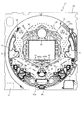
図2に示すように、遊技盤13は、正面視略正方形状に切削加工した木製のベース板60に、球案内用の多数の釘や風車およびレール61,62、一般入賞口63、第1入球口64、可変入賞装置65、可変表示装置ユニット80等を組み付けて構成され、その周縁部が内枠12の裏面側に取り付けられる。一般入賞口63、第1入球口64、可変入賞装置65、可変表示装置ユニット80は、ルータ加工によってベース板60に形成された貫通穴に配設され、遊技盤13の前面側から木ネジ等により固定されている。また、遊技盤13の前面中央部分は、前面枠14の窓部14c(図1参照)を通じて内枠12の前面側から視認することができる。以下に、主に図2を参照して、遊技盤13の構成について説明する。
As shown in FIG. 2, the
遊技盤13の前面には、帯状の金属板を略円弧状に屈曲加工して形成した外レール62が植立され、その外レール62の内側位置には外レール62と同様に帯状の金属板で形成した円弧状の内レール61が植立される。この内レール61と外レール62とにより遊技盤13の前面外周が囲まれ、遊技盤13とガラスユニット16(図1参照)とにより前後が囲まれることにより、遊技盤13の前面には、球の挙動により遊技が行われる遊技領域が形成される。遊技領域は、遊技盤13の前面であって2本のレール61,62と円弧部材70とにより区画して形成される略円形状の領域(入賞口等が配設され、発射された球が流下する領域)である。
An
2本のレール61,62は、球発射ユニット112a(図5参照)から発射された球を遊技盤13上部へ案内するために設けられたものである。内レール61の先端部分(図2の左上部)には戻り球防止部材68が取り付けられ、一旦、遊技盤13の上部へ案内された球が再度球案内通路内に戻ってしまうといった事態が防止される。外レール62の先端部(図2の右上部)には、球の最大飛翔部分に対応する位置に返しゴム69が取り付けられ、所定以上の勢いで発射された球は、返しゴム69に当たって、勢いが減衰されつつ中央部側へ跳ね返される。また、内レール61の右下側の先端部と外レール62の右上側の先端部との間には、レール間を繋ぐ円弧を内面側に設けて形成された樹脂製の円弧部材70がベース板60に打ち込んで固定されている。
The two
本パチンコ機10では、球が第1入球口64へ入球した場合に特別図柄(第1図柄)の抽選が行われ、球が第2入球口67を通過した場合に普通図柄(第2図柄)の抽選が行われる。第1入球口64への入球に対して行われる特別図柄の抽選では、特別図柄の大当たりか否かの当否判定が行われると共に、特別図柄の大当たりと判定された場合にはその大当たり種別の判定も行われる。特別図柄の大当たりになると、パチンコ機10が特別遊技状態へ移行すると共に、通常時には閉鎖されている特定入賞口65aが所定時間(例えば、30秒経過するまで、或いは、球が10個入賞するまで)開放され、その開放が5回(5ラウンド)繰り返される。その結果、その特定入賞口65aに多量の球が入賞するので、通常時より多量の賞球の払い出しが行われる。特別図柄の大当たり種別としては、「大当たりA」、「大当たりB」の2種類が設けられており、特別遊技状態の終了後には大当たり終了後の付加価値として、これらの大当たり種別に応じた遊技上の価値(遊技価値)が遊技者に付与される。
In the
また、特別図柄(第1図柄)の抽選が行われると、第1図柄表示装置37において特別図柄の変動表示(動的表示)が開始されて、所定時間(例えば、11秒〜60秒など)が経過した後に、抽選結果を示す特別図柄が停止表示される。第1図柄表示装置37において変動表示が行われている間に球が第1入球口64へ入球すると、その入球回数は最大4回まで保留され、その保留球数が第1図柄表示装置37により示されると共に、第3図柄表示装置81においても示される。第1図柄表示装置37において変動表示が終了した場合に、第1入球口64についての保留球数が残っていれば、次の特別図柄の抽選が行われると共に、その抽選に応じた変動表示が開始される。尚、パチンコ機10が特別遊技状態へ移行すると開閉される特別入賞口65aは、第1入球口64の直ぐ下に設けられている。よって、特別遊技状態中は、遊技者が特別入賞口65aに入賞させようとして球を打つので、第1入球口64にも球が多く入球する。従って、殆どの場合、パチンコ機10が特別遊技状態に移行している間に、第1入球口64についての保留球数は最大(4回)になる。
When a special symbol (first symbol) is drawn, the special symbol variable display (dynamic display) is started on the first
一方、第2入球口67における球の通過に対して行われる普通図柄の抽選では、普通図柄の当たりか否かの当否判定が行われる。普通図柄の当たりになると、所定時間(例えば、0.2秒または1秒)だけ第1入球口64に付随する電動役物が開放され、第1入球口64へ球が入球し易い状態になる。つまり、普通図柄の当たりになると、球が第1入球口64へ入球し易くなり、その結果、特別図柄の抽選が行われ易くなる。
On the other hand, in the normal symbol lottery performed for the passage of the ball at the
また、普通図柄(第2図柄)の抽選が行われると、第2図柄表示装置83において普通図柄の変動表示が開始されて、所定時間(例えば、3秒や30秒など)が経過した後に、抽選結果を示す普通図柄が停止表示される。第2図柄表示装置83において変動表示が行われている間に球が第2入球口67を通過すると、その通過回数は最大4回まで保留され、その保留球数が第1図柄表示装置37により表示されると共に、第2図柄保留ランプ84においても示される。第2図柄表示装置83において変動表示が終了した場合に、第2入球口67についての保留球数が残っていれば、次の普通図柄の抽選が行われると共に、その抽選に応じた変動表示が開始される。
In addition, when the normal symbol (the second symbol) is drawn, the normal symbol variation display is started on the second
上述したように、特別図柄の大当たり種別としては、「大当たりA」、「大当たりB」の2種類が設けられている。 As described above, there are two types of special jackpot types, “Big Jack A” and “Big Jack B”.
「大当たりA」、「大当たりB」になるといずれも、ラウンド数16ラウンドの特別遊技状態(16R大当たり)となり、その後、大当たり終了後の付加価値として、「大当たりA」であれば、次に大当たりとなるまでの間はパチンコ機10が特別図柄の高確率状態(特別図柄の確変中)へ移行する。一方、「大当たりB」であれば、その大当たりが終了してから、100回、抽選が実行されるまで(特別図柄の変動が開始されるまで)の間、普通図柄の時短状態となる。
Both “Big Jack A” and “Big Jack B” will be in a special gaming state with 16 rounds (16R jackpot). After that, if the jackpot value is “Big Jack A”, Until that time, the
ここで、「特別図柄の高確率状態」とは、特別図柄の大当たり確率がアップした状態、いわゆる特別図柄の確率状態(特別図柄の確変中)をいい、換言すれば、特別遊技状態(16R大当たり)へ移行し易い遊技の状態のことである。対して、「特別図柄の高確率状態」でない場合を「特別図柄の低確率状態」といい、これは特別図柄の確変状態よりも大当たり確率が低い状態、即ち、特別図柄の大当たり確率が通常の状態(特別図柄の通常状態)のことを示す。また、「普通図柄の時短状態」(普通図柄の時短中)とは、普通図柄の当たり確率がアップして、第1入球口64へ球が入球し易い遊技の状態のことをいう。対して、「普通図柄の時短状態」でない時を「普通図柄の通常状態」といい、これは普通図柄の当たり確率が通常の状態、即ち、時短中よりも当たり確率が低い状態のことを示す。
Here, the “high probability state of the special symbol” means a state where the special symbol jackpot probability is increased, that is, a so-called special symbol probability state (during special symbol change), in other words, the special gaming state (16R jackpot) ) Is a game state that is easy to shift to. On the other hand, a case that is not a “high probability state of a special symbol” is called a “low probability state of a special symbol”, which has a lower probability of jackpot than the probability variation state of a special symbol, that is, the jackpot probability of a special symbol is normal. Indicates the state (normal state of special symbol). The “normal symbol time-short state” (ordinary symbol time-short state) means a game state in which the probability of hitting the normal symbol increases and the ball easily enters the
上述したように、本実施形態における特別図柄の大当たりでは、大当たりの種別に関わらず大当たり時のラウンド数と、特別図柄の確変期間とを共通とし、その大当たりの種別に応じて「普通図柄の時短状態」となる期間を変えている。これに対して、大当たりの種別に応じてラウンド数を変えても良いし、大当たりの種別の一部のみラウンド数を変えても良い。また、例えば、大当たりの種別に応じて「普通図柄の時短状態」となる期間を変える代わりに、第1入球口64に付随する電動役物(図示せず)を開放する時間や、1回の普通図柄の当たりで電動役物を開放する回数を変更するものとしても良い。また、本実施形態では、大当たり終了後に、「特別図柄の高確率状態」および「普通図柄の時短状態」となるが、「特別図柄の高確率状態」が終了した後に、「普通図柄の時短状態」となるように構成しても良い。
As described above, in the special symbol jackpot in this embodiment, regardless of the type of jackpot, the number of rounds at the jackpot and the probability variation period of the special symbol are common, The period of “state” is changed. On the other hand, the number of rounds may be changed according to the type of jackpot, or the number of rounds may be changed only for a part of the jackpot type. Also, for example, instead of changing the period when the “normal symbol time-short state” is changed according to the type of jackpot, the time for opening the electric accessory (not shown) associated with the
本パチンコ機10では、電源などの投入等により初期設定が行われると、必ず「特別図柄の低確率状態」に設定される。その後、特別図柄の大当たりになると、「特別図柄の高確率状態」へ移行すると共に、「普通図柄の時短状態」へ移行する。
In the
遊技領域の正面視右側上部(図2の右側上部)には、発光手段である複数の発光ダイオード(以下、「LED」と略す。)37aと7セグメント表示器37bとが設けられた第1図柄表示装置37が配設されている。第1図柄表示装置37は、後述する主制御装置110で行われる各制御に応じた表示がなされるものであり、主にパチンコ機10の遊技状態の表示が行われる。複数のLED37aは、第1入球口64への入球(始動入賞)に伴って行われる特別図柄の抽選が実行中であるか否かを点灯状態により示すことによって変動表示を行ったり、変動終了後の停止図柄として、その特別図柄の抽選結果に応じた特別図柄(第1図柄)を点灯状態により示したり、第1入球口64に入球された球のうち変動が未実行である球(保留球)の数である保留球数を点灯状態により示すものである。
A first pattern provided with a plurality of light emitting diodes (hereinafter abbreviated as “LEDs”) 37a and a 7-
この第1図柄表示装置37において特別図柄(第1図柄)の変動表示が行われている間に球が第1入球口64へ入球した場合、その入球回数は最大4回まで保留され、その保留球数は第1図柄表示装置37により示されると共に、第3図柄表示装置81においても示される。なお、本実施形態においては、第1入球口64への入球は、最大4回まで保留されるように構成したが、最大保留回数は4回に限定されるものでなく、3回以下、又は、5回以上の回数(例えば、8回)に設定しても良い。
If a ball enters the
7セグメント表示器37bは、大当たり中のラウンド数やエラー表示を行うものである。なお、LED37aは、それぞれのLEDの発光色(例えば、赤、緑、青)が異なるよう構成され、その発光色の組み合わせにより、少ないLEDでパチンコ機10の各種遊技状態(特別図柄の高確率状態や、普通図柄の時短中など)を表示することができる。また、LED37aには、変動終了後の停止図柄として特別図柄の抽選結果が大当たりであるか否かが示されるだけでなく、大当たりである場合はその大当たり種別(大当たりA、大当たりB)に応じた特別図柄(第1図柄)が示される。
The 7-
また、遊技領域には、球が入賞することにより5個から15個の球が賞球として払い出される複数の一般入賞口63が配設されている。また、遊技領域の中央部分には、可変表示装置ユニット80が配設されている。可変表示装置ユニット80には、液晶ディスプレイ(以下単に「表示装置」と略す。)で構成された第3図柄表示装置81と、LEDで構成された第2図柄表示装置83とが設けられている。この可変表示装置ユニット80には、第3図柄表示装置81の外周を囲むようにして、センターフレーム86が配設されている。
The game area is provided with a plurality of general winning
第3図柄表示装置81は、第1図柄表示装置37の表示に応じた装飾的な表示を行うものである。例えば、第1入球口64へ球が入球(始動入賞)すると、それをトリガとして、第1図柄表示装置37において特別図柄(第1図柄)の変動表示が実行される。更に、第3図柄表示装置81では、その特別図柄の変動表示に同期して、その特別図柄の変動表示に対応する第3図柄の変動表示が行われる。
The third
第3図柄表示装置81は、8インチサイズの大型の液晶ディスプレイで構成されるものであり、後述する表示制御装置114によって表示内容が制御されることにより、例えば左、中及び右の3つの図柄列が表示される。各図柄列は複数の図柄によって構成され、これらの図柄が図柄列毎に縦スクロールして第3図柄表示装置81の表示画面上にて第3図柄が可変表示されるようになっている。本実施形態では、主制御装置110の制御に伴った遊技状態の表示が第1図柄表示装置37で行われるのに対して、第3図柄表示装置81はその第1図柄表示装置37の表示に応じた装飾的な表示が行われる。なお、表示装置に代えて、例えば、リール等を用いて第3図柄表示装置81を構成するようにしても良い。
The third
ここで、図4を参照して、第3図柄表示装置81の表示内容について説明する。図4は、第3図柄表示装置81の表示画面を説明するための図面であり、図4(a)は、表示画面の領域区分設定と有効ライン設定とを模式的に示した図であり、図4(b)は、実際の表示画面を例示した図である。
Here, with reference to FIG. 4, the display content of the 3rd
第3図柄は、「0」から「9」の数字を付した10種類の主図柄により構成されている。各主図柄は、木箱よりなる後方図柄の上に「0」から「9」の数字を付して構成され、そのうち奇数番号(1,3,5,7,9)を付した主図柄は、木箱の前面ほぼ一杯に大きな数字が付加されている。これに対し、偶数番号(0,2,4,6,8)を付した主図柄は、木箱の前面ほぼ一杯にかんな、風呂敷、ヘルメット等のキャラクタを模した付属図柄が付加されており、付属図柄の右下側に偶数の数字が緑色で小さく、且つ、付属図柄の前側に表示されるように付加されている。 The third symbol is composed of ten kinds of main symbols with numbers from “0” to “9”. Each main symbol is composed of numbers from “0” to “9” on the rear symbol consisting of a wooden box, of which the main symbols with odd numbers (1, 3, 5, 7, 9) are A large number is added to almost the front of the wooden box. On the other hand, the main symbols with even numbers (0, 2, 4, 6, 8) have attached symbols that imitate characters such as furoshiki, helmet, etc., almost full front of the wooden box, An even number is small in green on the lower right side of the attached symbol and is added so as to be displayed on the front side of the attached symbol.
また、本実施形態のパチンコ機10においては、後述する主制御装置110(図5参照)により行われる特別図柄の抽選結果が大当たりであった場合に、同一の主図柄が揃う変動表示が行われ、その変動表示が終わった後に大当たりが発生するよう構成されている。一方、特別図柄の抽選結果が外れであった場合は、同一の主図柄が揃わない変動表示が行われる。
Further, in the
例えば、特別図柄の抽選結果が「大当たりA」であれば、奇数番号である「1,3,5,7,9」が付加された主図柄が揃う変動表示が行われる。また、「大当たりB」であれば、偶数番号である「0,2,4,6,8」が付加された主図柄が揃う変動表示が行われる。また、「大当たりB」、「大当たりC」、「大当たりE」では、左右に同じ主図柄が停止し、中図柄にバトルという文字が示されたバトル図柄が停止する。一方、特別図柄の抽選結果が外れであれば、同一番号の主図柄が揃わない変動表示が行われる。 For example, if the lottery result of the special symbol is “Large A”, a variable display is performed in which the main symbols to which “1, 3, 5, 7, 9”, which is an odd number, are added are aligned. Further, if “big hit B”, the variable display is performed in which the main symbols to which the even numbers “0, 2, 4, 6, 8” are added are arranged. In addition, in “big hit B”, “big hit C”, and “big hit E”, the same main symbol is stopped on the left and right, and the battle symbol in which the character “battle” is shown in the middle symbol is stopped. On the other hand, if the lottery result of the special symbol is off, the variable display in which the main symbols of the same number are not aligned is performed.
図4(a)に示すように、第3図柄表示装置81の表示画面は、第3図柄を変動表示する主表示領域Dmで構成されている。主表示領域Dmは、左・中・右の3つの表示領域Dm1〜Dm3に区分けされており、その3つの表示領域Dm1〜Dm3に、それぞれ3つの図柄列Z1,Z2,Z3が表示される。各図柄列Z1〜Z3には、上述した第3図柄が規定の順序で表示される。即ち、各図柄列Z1〜Z3には、数字の昇順または降順に主図柄が配列され、各図柄列Z1〜Z3毎に周期性をもって上から下へとスクロールして変動表示が行われる。特に、左図柄列Z1においては主図柄の数字が降順に現れるように配列され、中図柄列Z2及び右図柄列Z3においては主図柄の数字が昇順に現れるように配列されている。
As shown in FIG. 4A, the display screen of the third
また、主表示領域Dmには、各図柄列Z1〜Z3毎に上・中・下の3段に第3図柄が表示される。この主表示領域Dmの中段部が有効ラインL1として設定されており、毎回の遊技に際して、左図柄列Z1→右図柄列Z3→中図柄列Z2の順に、有効ラインL1上に第3図柄が停止表示される。その第3図柄の停止時に有効ラインL1上に大当たり図柄の組合せ(本実施形態では、同一の主図柄の組合せ)で揃えば大当たりとして大当たり動画が表示される。 In the main display area Dm, the third symbols are displayed in the upper, middle, and lower three rows for each symbol row Z1 to Z3. The middle part of the main display area Dm is set as the active line L1, and in each game, the third symbol stops on the active line L1 in the order of the left symbol row Z1, the right symbol row Z3, and the middle symbol row Z2. Is displayed. If the combination of jackpot symbols (the same main symbol combination in this embodiment) is arranged on the effective line L1 when the third symbol is stopped, a jackpot moving image is displayed as a jackpot.
なお、本実施形態においては、第1入球口64への入球は、最大4回まで保留されるように構成したが、最大保留球数は4回に限定されるものでなく、3回以下、又は、5回以上の回数(例えば、8回)に設定しても良い。
In the present embodiment, the ball entering the
図2に戻って、説明を続ける。第2図柄表示装置83は、球が第2入球口67を通過することに伴って行われる普通図柄の抽選が実行中であるか否かを点灯状態により示すことによって変動表示を行ったり、変動終了後の停止図柄として、その普通図柄の抽選結果に応じた普通図柄(第2図柄)を点灯状態により示すものである。
Returning to FIG. 2, the description will be continued. The second
より具体的には、第2図柄表示装置83では、球が第2入球口67を通過する毎に、第2図柄としての「○」の図柄と「×」の図柄とを交互に点灯させる変動表示が行われる。パチンコ機10は、第2図柄表示装置83における変動表示が所定図柄(本実施形態においては「○」の図柄)で停止すると、第1入球口64に付随する電動役物が所定時間だけ作動状態となり(開放される)、その結果、第1入球口64に球が入り易い状態となるように構成されている。球が第2入球口67を通過した通過回数は最大4回まで保留され、その保留球数が上述した第1図柄表示装置37により表示されると共に第2図柄保留ランプ84においても点灯表示される。第2図柄保留ランプ84は、最大保留数分の4つ設けられ、第3図柄表示装置81の下方に左右対称に配設されている。
More specifically, in the second
なお、普通図柄(第2図柄)の変動表示は、本実施形態のように、第2図柄表示装置83において複数のランプの点灯と非点灯を切り換えることにより行うものの他、第1図柄表示装置37及び第3図柄表示装置81の一部を使用して行うようにしても良い。同様に、第2図柄保留ランプ84の点灯を第3図柄表示装置81の一部で行うようにしても良い。また、第2入球口67における球の通過は、第1入球口64と同様に、最大保留球数は4回に限定されるものでなく、3回以下、又は、5回以上の回数(例えば、8回)に設定しても良い。また、第1図柄表示装置37により保留球数が示されるので、第2図柄保留ランプ84により点灯表示を行わないものとしても良い。
The normal symbol (second symbol) variable display is performed by switching on and off of a plurality of lamps in the second
また、第2図柄保留ランプ84の下方には、バトル報知ランプ800aとミッション報知ランプ800bとが左右に設けられている。このバトル報知ランプ800aとミッション報知ランプ800bは、後述する、バトル演出、ミッション演出が選択されたことを遊技者に報知するための報知ランプである。図4(b)に、バトル報知ランプ800aとミッション報知ランプ800bとの拡大図を示した。バトル報知ランプ800aは、赤色のLEDがその裏面側に配置され、ミッション報知ランプ800bは、青色のLEDがその裏面側に配置されている。このように、バトル報知ランプ800aとミッション報知ランプ800bとの点灯色を異ならせることで、遊技者に、バトル報知ランプ800aとミッション報知ランプ800bとを識別させ易くできる。
Also, below the second
詳細については、後述するが、第3図柄にバトル報知図柄が付与された場合、または、ミッション報知図柄が付与された場合には、このバトル報知ランプ800aとミッション報知ランプ800bとがそれぞれ点滅して点灯される。その後、第3図柄表示装置81にバトル図柄が停止表示されると、バトル報知ランプ800aが点灯される。一方、ミッション図柄が停止表示されると、ミッション報知ランプ800bが点灯表示される。
Although details will be described later, when the battle notification symbol is assigned to the third symbol, or when the mission notification symbol is assigned, the
可変表示装置ユニット80の下方には、球が入球し得る第1入球口64が配設されている。この第1入球口64へ球が入球すると遊技盤13の裏面側に設けられる第1入球口スイッチ(図示せず)がオンとなり、その第1入球口スイッチのオンに起因して主制御装置110で特別図柄の抽選がなされ、その抽選結果に応じた表示が第1図柄表示装置37のLED37aで示される。また、第1入球口64は、球が入球すると5個の球が賞球として払い出される入賞口の1つにもなっている。
Below the variable
第1入球口64の下方には可変入賞装置65が配設されており、その略中央部分に横長矩形状の特定入賞口(大開放口)65aが設けられている。パチンコ機10においては、主制御装置110で行われる特別図柄の抽選が大当たりとなると、所定時間(変動時間)が経過した後に、大当たりの停止図柄となるよう第1図柄表示装置37のLED37aを点灯させると共に、その大当たりに対応した第3図柄の停止図柄を第3図柄表示装置81に表示させて、大当たりの発生が示される。その後、通常時より多量の賞球の払い出しが行われる特別遊技状態(16ラウンドの大当たり)に遊技状態が遷移する。この特別遊技状態として、通常時には閉鎖されている特定入賞口65aが、所定時間(例えば、30秒経過するまで、或いは、球が10個入賞するまで)開放される。
A variable winning
この特定入賞口65aは、所定時間が経過すると閉鎖され、その閉鎖後、再度、その特定入賞口65aが所定時間開放される。この特定入賞口65aの開閉動作は、16回(16ラウンド)繰り返し可能にされている。この開閉動作が行われている状態が、遊技者にとって有利な特別遊技状態の一形態であり、遊技者には、遊技上の価値(遊技価値)の付与として通常時より多量の賞球の払い出しが行われる。
The
可変入賞装置65は、具体的には、特定入賞口65aを覆う横長矩形状の開閉板と、その開閉板の下辺を軸として前方側に開閉駆動するための大開放口ソレノイド(図示せず)とを備えている。特定入賞口65aは、通常時は、球が入賞できないか又は入賞し難い閉状態になっている。大当たりの際には大開放口ソレノイドを駆動して開閉板を前面下側に傾倒し、球が特定入賞口65aに入賞しやすい開状態を一時的に形成し、その開状態と通常時の閉状態との状態を交互に繰り返すように作動する。
Specifically, the variable winning
なお、上記した形態に特別遊技状態は限定されるものではない。特定入賞口65aとは別に開閉される大開放口を遊技領域に設け、第1図柄表示装置37において大当たりに対応したLED37aが点灯した場合に、特定入賞口65aが所定時間開放され、その特定入賞口65aの開放中に、球が特定入賞口65a内へ入賞することを契機として特定入賞口65aとは別に設けられた大開放口が所定時間、所定回数開放される遊技状態を特別遊技状態として形成するようにしても良い。
Note that the special gaming state is not limited to the above-described form. When the game area is provided with a large opening that is opened and closed separately from the specific winning
遊技盤13の下側における左右の隅部には、証紙や識別ラベル等を貼着するための貼着スペースK1,K2が設けられ、貼着スペースK1に貼られた証紙等は、前面枠14の小窓35(図1参照)を通じて視認することができる。
Adhesive spaces K1 and K2 for adhering certificate stamps, identification labels, and the like are provided at the left and right corners on the lower side of the
更に、遊技盤13には、アウト口66が設けられている。いずれの入賞口63,64,65aにも入球しなかった球はアウト口66を通って図示しない球排出路へと案内される。遊技盤13には、球の落下方向を適宜分散、調整等するために多数の釘が植設されているとともに、風車等の各種部材(役物)が配設されている。
Further, the
図3に示すように、パチンコ機10の背面側には、制御基板ユニット90,91と、裏パックユニット94とが主に備えられている。制御基板ユニット90は、主基板(主制御装置110)と音声ランプ制御基板(音声ランプ制御装置113)と表示制御基板(表示制御装置114)とが搭載されてユニット化されている。制御基板ユニット91は、払出制御基板(払出制御装置111)と発射制御基板(発射制御装置112)と電源基板(電源装置115)とカードユニット接続基板116とが搭載されてユニット化されている。
As shown in FIG. 3,
裏パックユニット94は、保護カバー部を形成する裏パック92と払出ユニット93とがユニット化されている。また、各制御基板には、各制御を司る1チップマイコンとしてのMPU、各種機器との連絡をとるポート、各種抽選の際に用いられる乱数発生器、時間計数や同期を図る場合などに使用されるクロックパルス発生回路等が、必要に応じて搭載されている。
The
なお、主制御装置110、音声ランプ制御装置113及び表示制御装置114、払出制御装置111及び発射制御装置112、電源装置115、カードユニット接続基板116は、それぞれ基板ボックス100〜104に収納されている。基板ボックス100〜104は、ボックスベースと該ボックスベースの開口部を覆うボックスカバーとを備えており、そのボックスベースとボックスカバーとが互いに連結されて、各制御装置や各基板が収納される。
The
また、基板ボックス100(主制御装置110)及び基板ボックス102(払出制御装置111及び発射制御装置112)は、ボックスベースとボックスカバーとを封印ユニット(図示せず)によって開封不能に連結(かしめ構造による連結)している。また、ボックスベースとボックスカバーとの連結部には、ボックスベースとボックスカバーとに亘って封印シール(図示せず)が貼着されている。この封印シールは、脆性な素材で構成されており、基板ボックス100,102を開封するために封印シールを剥がそうとしたり、基板ボックス100,102を無理に開封しようとすると、ボックスベース側とボックスカバー側とに切断される。よって、封印ユニット又は封印シールを確認することで、基板ボックス100,102が開封されたかどうかを知ることができる。
Further, the substrate box 100 (main control device 110) and the substrate box 102 (dispensing
払出ユニット93は、裏パックユニット94の最上部に位置して上方に開口したタンク130と、タンク130の下方に連結され下流側に向けて緩やかに傾斜するタンクレール131と、タンクレール131の下流側に縦向きに連結されるケースレール132と、ケースレール132の最下流部に設けられ、払出モータ216(図15参照)の所定の電気的構成により球の払出を行う払出装置133とを備えている。タンク130には、遊技ホールの島設備から供給される球が逐次補給され、払出装置133により必要個数の球の払い出しが適宜行われる。タンクレール131には、当該タンクレール131に振動を付加するためのバイブレータ134が取り付けられている。
The
また、払出制御装置111には状態復帰スイッチ120が設けられ、発射制御装置112には可変抵抗器の操作つまみ121が設けられ、電源装置115にはRAM消去スイッチ122が設けられている。状態復帰スイッチ120は、例えば、払出モータ216(図15参照)部の球詰まり等、払出エラーの発生時に球詰まりを解消(正常状態への復帰)するために操作される。操作つまみ121は、発射ソレノイドの発射力を調整するために操作される。RAM消去スイッチ122は、パチンコ機10を初期状態に戻したい場合に電源投入時に操作される。
The
<本実施形態における第3図柄表示装置81で表示される表示態様について>
図5(a)に示すように、第3図柄表示装置81には、主図柄である第3図柄が抽選遊技の開始に基づいて変動表示(動的表示)される。予め定められた所定時間の間、変動表示した後に、変動開始時に予め定められた停止図柄で左図柄列(Z1)、右図柄列(Z3)、中図柄列(Z2)の順で、第3図柄が停止される。
<About the display mode displayed on the 3rd
As shown in FIG. 5A, the third
図5(b)に示すように、左図柄列(Z1)と右図柄列(Z3)との図柄がそれぞれ同じ図柄で停止されたリーチ表示態様となると、中図柄列(Z2)が低速で変動表示され、リーチ表示態様で停止されている図柄と同じ図柄で停止されて、大当たりとなるか否かの演出表示が実行される。その後、所定時間経過後に、予め定められた図柄で中図柄列(Z2)が停止表示される。 As shown in FIG. 5 (b), when the left symbol row (Z1) and the right symbol row (Z3) are in the reach display mode in which the symbols are stopped at the same symbol, the middle symbol row (Z2) fluctuates at a low speed. It is displayed and the display is stopped with the same symbol as the symbol stopped in the reach display mode, and the effect display of whether or not it is a big win is executed. Thereafter, after a predetermined time has elapsed, the middle symbol row (Z2) is stopped and displayed with a predetermined symbol.
図6(a)に示した表示態様は、リーチ表示態様となった場合に、バトル報知図柄が、左図柄列(Z1)と右図柄列(Z3)との図柄に付与されて、そのバトル報知図柄が第3図柄の周りを周回するように変動表示される表示態様を示している。このように、バトル報知図柄が、第3図柄に付与されると、この変動表示で遊技者に大当たりAまたは大当たりDが付与されることを示す停止図柄(本実施形態では、同じ図柄のぞろ目で停止表示される図柄)で第3図柄が停止表示されなかった場合に、図6(b)に示すようにバトル図柄が中図柄列(Z2)に停止することを遊技者に報知している。 When the display mode shown in FIG. 6 (a) is the reach display mode, the battle notification symbols are assigned to the symbols of the left symbol sequence (Z1) and the right symbol sequence (Z3), and the battle notification is performed. A display mode is shown in which the symbols are variably displayed so as to circulate around the third symbol. In this way, when the battle notification symbol is given to the third symbol, the stop symbol (in this embodiment, a set of the same symbols) indicating that the player receives a jackpot A or a jackpot D by this variable display. When the third symbol is not stopped and displayed by the eye), the player is informed that the battle symbol stops in the middle symbol row (Z2) as shown in FIG. 6B. Yes.
詳細については、後述するが、このバトル図柄が中図柄列(Z2)に停止表示されると、図8(a)に示すようなバトル演出が表示される。なお、このバトル図柄は、大当たりB、大当たりC、大当たりE、小当たりのいずれかの当否判定結果が判定されていることに基づいて中図柄列(Z2)に停止表示される。即ち、バトル報知図柄が第3図柄の変動中に付与されると、大当たりA、大当たりDが付与されなかった場合にも、遊技者に少なくとも、大当たりB、大当たりC、大当たりE、小当たりのいずれかの当たりが確定していることを報知している。 Although details will be described later, when this battle symbol is stopped and displayed in the middle symbol row (Z2), a battle effect as shown in FIG. 8A is displayed. Note that this battle symbol is stopped and displayed in the middle symbol row (Z2) based on the determination result of any one of the big hit B, big hit C, big hit E, and small hit. That is, if the battle notification symbol is given during the change of the third symbol, even if the jackpot A or jackpot D is not given, at least one of the jackpot B, jackpot C, jackpot E, or jackpot will be given to the player It is informing that the hit is fixed.
これによって、遊技者は、大当たりAまたは大当たりDが付与されなかった場合にも、その他の大当たりか、小当たりが付与されることを早期に識別でき、安心して遊技を行うことができる。よって、バトル報知図柄が停止表示されることを期待しながら遊技を行うことができる。 Thus, even if the jackpot A or jackpot D is not awarded, the player can identify early that other jackpots or jackpots will be awarded, and can play the game with peace of mind. Therefore, it is possible to play a game while expecting the battle notification symbols to be stopped and displayed.
また、バトル演出では、特定入賞口65aが開放されて、所定の大当たり遊技または小当たりが実行される。その大当たり遊技中には、第3図柄表示装置81には、図8(a)に示すように遊技者(プレイヤー)が敵(遊技機側)と魚釣りの勝負をする演出が表示される。特定入賞口65aに遊技球が入賞することに基づいて、プレイヤーが魚を釣れるか否かの演出が表示される。魚を釣ると、第3図柄表示装置81の表示領域の可部に表示されているインジケーターの1メモリ分が点灯して、魚を釣った数を報知する構成となっている。なお、この魚釣り演出が実行されている場合には、特定入賞口65aは、短時間(例えば、1秒間)の開放時間で複数回開放する開放制御が実行され、特定入賞口65aへの遊技球の入賞が困難に構成されている。そして、本実施形態では、プレイヤーが魚を4匹以上釣り上げると、大漁モード(図8(b)参照)という特定入賞口65aが長時間(本実施形態では、30秒または10球入賞するまで)の間、開放される大当たり遊技が実行される。なお、この大漁モードは、大当たりB、大当たりEである場合に実行される。
In the battle effect, the specific winning
このように、実際の抽選では、変動開始時に、大当たりの種別は決定されているが、大当たり遊技の開始から所定期間の間(本実施形態では、大当たり遊技の2Rが実行されるまでの間)において、大当たりの種別が大当たりBまたは大当たりEのいずれであるか否かの演出表示を特定入賞口65aに遊技球が入賞することに関わって実行することで、遊技者に、特定入賞口65aにより多くの遊技球を入賞させた方が、大当たりBまたは大当たりEが付与されるように思わせることができる。
In this way, in the actual lottery, the type of jackpot is determined at the start of variation, but during the predetermined period from the start of the jackpot game (in this embodiment, until 2R of jackpot game is executed) In this case, by performing the effect display of whether the jackpot type is the jackpot B or the jackpot E in relation to the winning of the game ball in the specific winning
なお、この大当たりB、大当たりC、大当たりE、小当たりである場合には、大当たり遊技の2Rまでは、特定入賞口65aに遊技球を入賞させることは困難(発射させた遊技球の数に対して、特定入賞口65aに入賞した遊技球の数の割合が少ない)であるように設定されている。よって、2Rまでは、多くの場合で、発射した遊技球の数の方が、特定入賞口65aに入賞したことに基づいて払い出される遊技球の数よりも多くなる。即ち、遊技者が損をする構成となっているが、遊技者は、バトル演出の演出表示態様を楽しむことで、損をしたことに注意が低下して、遊技を楽しむことができる。よって、遊技者に楽しんでもらいながら、遊技店側の利益を増大させることができる。
In the case of the jackpot B, jackpot C, jackpot E, and jackpot, it is difficult to win a game ball in the
また、図8(b)に示した大漁モードで実行される大当たり遊技では、特定入賞口65aに遊技球が入賞したことに基づいて、魚が釣れたか否かの演出が表示され、魚が釣れたことに基づいて、第3図柄表示装置81の表示領域の下部に表示されたインジケーターのメモリが1ずつ点灯表示される。このメモリが多くなればなるほど、この大当たりの種別が、大当たりB、即ち、確変大当たりである可能性が高い(確変大当たりである場合に、通常大当たりである場合よりもメモリが多くなり易い)ということを示している。
Further, in the big hit game executed in the big fishing mode shown in FIG. 8B, based on the fact that the game ball has won the specific winning
よって、遊技者は、大当たり遊技中に、特定入賞口65aに遊技球を入賞させることがより楽しくなり、大当たり遊技の価値を得られる遊技球(賞球)以上に向上させることができる。また、大当たり遊技を飽きることなく、第3図柄表示装置81で表示される演出を楽しむことができる。
Therefore, it becomes more fun for the player to win a game ball at the specific winning
次に、図7(a)に示した表示態様は、バトル報知図柄とミッション報知図柄とがそれぞれリーチ表示態様で表示されている第3図柄に付与された場合の表示態様を示したものである。バトル報知図柄とミッション報知図柄とが交互に第3図柄の周りを周回するように変動表示されることで、遊技者に、第3図柄の表示態様が大当たりAまたは大当たりDを示す停止表示態様で停止表示されなかった場合にも、バトル図柄またはミッション図柄のいずれか一方が中図柄列(Z2)に停止表示されることを報知している。 Next, the display mode shown in FIG. 7A shows the display mode when the battle notification symbol and the mission notification symbol are each given to the third symbol displayed in the reach display mode. . The battle notification symbol and the mission notification symbol are alternately displayed so as to circulate around the third symbol, so that the player can display the third symbol in a stop display mode in which the jackpot A or jackpot D is displayed. Even when the stop display is not performed, it is informed that either the battle symbol or the mission symbol is stopped and displayed in the middle symbol row (Z2).
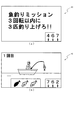
ミッション図柄が中図柄列(Z2)に停止表示されることで、ミッション演出が、その後の抽選遊技を利用して実行される。ミッション演出については、詳細について、後述するが、保留されている抽選遊技の当否判定結果や、選択される変動パターンを変動開始前に判別して、複数回の抽選遊技に跨った演出が実行される。本実施形態では、ミッション演出の最初の抽選遊技において、そのミッション演出の内容が報知される。図9(a)に示した例では、抽選遊技の開始において、「魚釣りミッション」というミッションの題名を示す文字が表示され、「3回転以内に3匹釣り上げろ!!」というミッションの内容が表示されている。このミッションの内容は、連続した3回の抽選遊技が実行されるまでに、魚を3匹釣りあげる表示態様が表示されると、遊技者に大当たりが付与されることを示している。なお、本実施形態では、ミッション演出の内容は、その他設定されており、例えば、抽選遊技の回数ではなく、3分間等の時間の制限であってもよい。また、ミッションの内容としても、本実施形態の内容に関わらず、第3図柄を変動表示させて、所定の図柄(例えば、7図柄)で所定回数リーチ表示態様で停止表示させるような内容であってもよい。 The mission effect is executed by using the lottery game after the mission symbol is stopped and displayed in the middle symbol row (Z2). The mission effect will be described in detail later, but the determination result of the lottery game being held or the variation pattern to be selected is determined before the start of the variation, and the effect over multiple lottery games is executed. The In the present embodiment, the content of the mission effect is notified in the first lottery game of the mission effect. In the example shown in FIG. 9A, at the start of the lottery game, a character indicating the title of the mission “fishing mission” is displayed, and the content of the mission “Five 3 fish within 3 rotations!” Is displayed. Has been. The contents of this mission indicate that a jackpot is awarded to a player when a display mode for picking up three fish is displayed before three consecutive lottery games are executed. In the present embodiment, the contents of the mission effect are set in addition, and may be, for example, a time limit such as 3 minutes instead of the number of lottery games. Also, the contents of the mission are such that, regardless of the contents of the present embodiment, the third symbol is variably displayed, and is stopped and displayed in a predetermined number of times with a predetermined symbol (for example, seven symbols). May be.
また、本実施形態では、ミッション内容が達成された場合には、大当たりが付与されることを報知する構成としたが、それに限らず、スーパーリーチとなる表示態様が変動表示されることを報知する構成であってもよい。 Further, in the present embodiment, when the mission content is achieved, it is configured to notify that the jackpot is awarded, but not limited thereto, it is notified that the display mode that becomes super reach is variably displayed. It may be a configuration.
図9(b)に示すように、ミッション中の抽選遊技では、ミッション開始からの抽選遊技の回数が表示領域の左上に表示される(図9(b)では、「1回目」の文字)。また、釣り上げた魚の数を示す図柄が表示領域の下部に魚の形を模して示されており、釣り上げると左から順に色が可変(例えば、白から青)されて表示される。ミッションの演出表示中にも第3図柄は、変動表示されるが、図9(a)〜(b)に示すように、右下に縮小されて変動表示される。なお、第3図柄の変動時間は、主制御装置110によって決定された変動時間で変動表示される。通常時には、その主制御装置110から出力される変動パターンコマンドに基づいて、その変動パターンコマンドが示す変動表示が実行されるが、ミッション時には、音声ランプ制御装置113によって、その変動表示が同一の変動時間でミッションの表示態様に置き換える制御処理が実行される。
As shown in FIG. 9B, in the lottery game during the mission, the number of lottery games from the start of the mission is displayed on the upper left of the display area (in FIG. 9B, “first” character). In addition, a pattern indicating the number of fish that have been picked up is shown at the bottom of the display area, imitating the shape of a fish, and when the fish is picked up, the color is changed in order from the left (for example, white to blue) and displayed. While the mission effect is displayed, the third symbol is variably displayed. However, as shown in FIGS. 9A to 9B, the third symbol is variably displayed at the lower right. Note that the variation time of the third symbol is variably displayed with the variation time determined by the
図10は、バトル図柄またはミッション図柄が停止表示される変動表示態様の別例を示した例である。図10(a)は、この変動表示態様の変動開始時の第3図柄表示装置81に表示された表示態様を示した図である。図10(a)に示すように、この変動表示態様の名前を示す表示態様(タイトル)が表示される。この場合、第3図柄は、図10(a)に示すように、第3図柄表示装置81の右下に縮小して表示される。
FIG. 10 is an example showing another example of the variation display mode in which the battle symbol or the mission symbol is stopped and displayed. FIG. 10A is a diagram showing a display mode displayed on the third
次に、第3図柄が変動表示されて、図10(b)に示すように、左図柄列(Z1)と右図柄列(Z3)が停止表示される。このとき、停止表示される図柄列の組み合わせにより、中図柄列(Z2)にバトル図柄、ミッション図柄、バトルまたはミッション図柄のいずれかが停止するかの期待度を遊技者に報知する構成となっている。本実施形態では、図11に示したように、左図柄列(Z1)には、1〜7までの図柄が停止する構成となっており、7に近づく程、期待度が高い(中図柄列(Z2)にバトル図柄、ミッション図柄、バトルまたはミッション図柄が停止し易い)ことを示している。
Next, the third symbol is variably displayed, and the left symbol row (Z1) and the right symbol row (Z3) are stopped and displayed as shown in FIG. 10 (b). At this time, according to the combination of the symbol sequences that are stopped and displayed, the player is notified of the expected degree of whether the battle symbol, the mission symbol, the battle, or the mission symbol is stopped in the middle symbol row (Z2). Yes. In the present embodiment, as shown in FIG. 11, the left symbol row (Z1) is configured such that
図11(a)では、左図柄列(Z1)に「1」、右図柄列(Z3)に「4」が停止して、期待度は一番低く構成されている。なお、図11(a)では、中図柄列(Z2)にバトル図柄が停止表示された例が示されている。図11(b)では、左図柄列(Z1)に「5」、右図柄列(Z3)に2が停止して、中図柄列(Z2)に、ミッション図柄が停止した例を示している。この場合、期待度は、中程度の期待度を報知している。図11(c)では、左図柄列(Z1)に「7」、右図柄列(Z3)に「6」が停止表示されて、最も、期待度が高いことを遊技者に報知している。図11(c)では、中図柄列(Z2)にバトル図柄が停止表示されたことを示している。 In FIG. 11A, “1” is stopped in the left symbol row (Z1) and “4” is stopped in the right symbol row (Z3), and the degree of expectation is the lowest. FIG. 11A shows an example in which the battle symbol is stopped and displayed in the middle symbol row (Z2). FIG. 11B shows an example in which “5” is stopped in the left symbol row (Z1), 2 is stopped in the right symbol row (Z3), and the mission symbol is stopped in the middle symbol row (Z2). In this case, the degree of expectation reports a medium degree of expectation. In FIG. 11C, “7” is stopped in the left symbol row (Z1) and “6” is stopped in the right symbol row (Z3) to notify the player that the expectation is the highest. FIG. 11C shows that the battle symbol is stopped and displayed in the middle symbol row (Z2).
なお、中図柄列(Z2)にバトルまたはミッション図柄(バトルorミッション図柄)が停止表示されると、バトル演出かミッション演出とのどちらか一方が実行されることを示している。遊技者は、その後の演出がどちらが開始されるかを楽しみに遊技を行うことができる。 When a battle or mission symbol (battle or mission symbol) is stopped and displayed in the middle symbol row (Z2), it indicates that one of the battle effect or the mission effect is executed. The player can play the game looking forward to which of the subsequent productions will start.
図12〜図14は、確変遊技状態であることを示す「大海モード」という遊技中に、変動表示中に出力される音楽(歌)とその音楽の歌詞を第3図柄表示装置81に表示された場合の例を示した図である。「大海モード」では、第3図柄表示装置81に海の上の船に乗ったキャラクターが釣りをする表示態様が表示されて、その船の上から釣りをする表示態様が表示される。キャラクターが魚を釣り上げると大当たりであることが報知される構成となっている。ここで、大当たり種別は、大当たりA〜Eまでのいずれかが抽選により決定される。
FIGS. 12 to 14 show the music (song) and the lyrics of the music that are output during the variable display during the game “Ohumi mode” indicating that the game is in the probability variation game state. FIG. In the “large sea mode”, a display mode in which a character on a ship on the sea fishes is displayed on the third
図12(a)では、第3図柄が右上で縮小して変動表示され、その間、音声出力装置226(スピーカー)より音楽(歌)が出力される場合の表示態様を示している。また、第3図柄表示装置81には、その出力されている音楽の歌詞が文字表示され、音楽の進行に合わせて表示される歌詞も色が順に白抜き文字から白色の文字に変化して表示される。
FIG. 12A shows a display mode in which the third symbol is reduced and displayed in the upper right and variably displayed, and during that time music (song) is output from the audio output device 226 (speaker). In addition, the 3rd
図12(b)では、図12(a)で示した音楽が進行し、次の歌詞が表示される。図12(b)に示した表示態様では、第3図柄表示装置81に「でっかい魚を追い求め」と表示されているが、音声出力装置226からは、「でっかい」までが出力されたところで、図13(a)に示すように、魚が釣り針にかかった表示態様となり、第3図柄がリーチ表示態様となるように構成される。その間には、音楽の出力が停止し、歌詞表示も非表示となる。その図13(a)に示す表示多様で、魚を釣りあげる表示態様が表示されると、第3図柄も大当たりAまたは大当たりDのいずれかで表示されて、遊技者に大当たり遊技が付与される、。
In FIG. 12B, the music shown in FIG. 12A progresses and the next lyrics are displayed. In the display mode shown in FIG. 12 (b), “Pursue a big fish” is displayed on the third
一方、図13(b)に示すように、魚が釣り針から逃げてしまう表示態様が表示されると、第3図柄が外れである表示態様で停止表示される。その後、図14(a)に示すように、再び、魚釣りをする表示態様が表示され、音楽は、その間に、進行していた歌の内容から引き続き出力され、第3図柄表示装置81に、その歌に合わせた歌詞が表示される。このように、歌が出力されない間にも、歌は進行するように構成されたので、遊技者に毎回同じ歌を聴かせてしまう不具合を防止できる。
On the other hand, as shown in FIG. 13B, when the display mode in which the fish escapes from the fishhook is displayed, the display is stopped in the display mode in which the third symbol is out of place. Thereafter, as shown in FIG. 14 (a), the display mode for fishing is displayed again, and the music continues to be output from the contents of the song that was in progress during that time, and the third
また、たとえば、確変中に休憩を遊技者がとった場合にも、その間に、音楽が出力されなくとも、歌の進行は継続されるので、遊技者は、休憩後に、どの程度休憩をしていたかを、歌の進行具合で把握することができる。 Also, for example, if a player takes a break during probability change, the song will continue to progress even if no music is output during that time, so the player will take a break after the break. Can be grasped by the progress of the song.
<パチンコ機10の電気的構成>
次に、図15を参照して、本パチンコ機10の電気的構成について説明する。図15は、パチンコ機10の電気的構成を示すブロック図である。
<Electric configuration of
Next, the electrical configuration of the
<主制御装置110の電気的構成>
主制御装置110には、演算装置である1チップマイコンとしてのMPU201が搭載されている。MPU201には、該MPU201により実行される各種の制御プログラムや固定値データを記憶したROM202と、そのROM202内に記憶される制御プログラムの実行に際して各種のデータ等を一時的に記憶するためのメモリであるRAM203と、そのほか、割込回路やタイマ回路、データ送受信回路などの各種回路が内蔵されている。なお、払出制御装置111や音声ランプ制御装置113などのサブ制御装置に対して動作を指示するために、主制御装置110から該サブ制御装置へ各種のコマンドがデータ送受信回路によって送信されるが、かかるコマンドは、主制御装置110からサブ制御装置へ一方向にのみ送信される。
<Electrical configuration of
The
主制御装置110では、特別図柄の抽選、普通図柄の抽選、第1図柄表示装置37における表示の設定、第2図柄表示装置83における表示の設定、および、第3図柄表示装置81における表示の設定といったパチンコ機10の主要な処理を実行する。そして、RAM203には、これらの処理を制御するための各種カウンタが設けられている。ここで、図6を参照して、主制御装置110のRAM203内に設けられるカウンタ等について説明する。これらのカウンタ等は、特別図柄の抽選、普通図柄の抽選、第1図柄表示装置37における表示の設定、第2図柄表示装置83における表示の設定、および、第3図柄表示装置81における表示の設定などを行うために、主制御装置110のMPU201で使用される。
In
特別図柄の抽選や、第1図柄表示装置37および第3図柄表示装置81の表示の設定には、図16に示すように、特別図柄の抽選に使用する第1当たり乱数カウンタC1と、特別図柄の大当たり種別を選択するために使用する第1当たり種別カウンタC2と、特別図柄における外れの停止種別を選択するために使用する停止種別選択カウンタC3と、第1当たり乱数カウンタC1の初期値設定に使用する第1初期値乱数カウンタCINI1と、変動パターン選択に使用する変動種別カウンタCS1とが用いられる。また、普通図柄の抽選には、第2当たり乱数カウンタC4が用いられ、第2当たり乱数カウンタC4の初期値設定には第2初期値乱数カウンタCINI2が用いられる。これら各カウンタは、更新の都度、前回値に1が加算され、最大値に達した後0に戻るループカウンタとなっている。
As shown in FIG. 16, for the special symbol lottery and the display setting of the first
各カウンタは、例えば、タイマ割込処理(図25参照)の実行間隔である2ミリ秒間隔で更新され、また、一部のカウンタは、メイン処理(図32参照)の中で不定期に更新されて、その更新値がRAM203の所定領域に設定されたカウンタ用バッファに適宜格納される。RAM203には、1つの実行エリアと4つの保留エリア(保留第1〜第4エリア)とからなる特別図柄保留球格納エリア203aが設けられており、これらの各エリアには、第1入球口64への入球タイミングに合わせて、第1当たり乱数カウンタC1、第1当たり種別カウンタC2、停止種別選択カウンタC3、変動種別カウンタCS1の各値がそれぞれ格納される。また、RAM203には、1つの実行エリアと4つの保留エリア(保留第1〜第4エリア)とからなる普通図柄保留球格納エリア203bが設けられており、これらの各エリアには、球が左右何れかの第2入球口(スルーゲート)67を通過したタイミングに合わせて、第2当たり乱数カウンタC4の値が格納される。
Each counter is updated, for example, at an interval of 2 milliseconds, which is the execution interval of the timer interrupt process (see FIG. 25), and some counters are updated irregularly in the main process (see FIG. 32). Then, the updated value is appropriately stored in a counter buffer set in a predetermined area of the
各カウンタについて詳しく説明する。第1当たり乱数カウンタC1は、所定の範囲(例えば、0〜299)内で順に1ずつ加算され、最大値(例えば、0〜299の値を取り得るカウンタの場合は299)に達した後0に戻る構成となっている。特に、第1当たり乱数カウンタC1が1周した場合、その時点の第1初期値乱数カウンタCINI1の値が当該第1当たり乱数カウンタC1の初期値として読み込まれる。 Each counter will be described in detail. The first per-random number counter C1 is incremented by 1 within a predetermined range (for example, 0 to 299) and reaches 0 after reaching the maximum value (for example, 299 for a counter that can take a value of 0 to 299). It is the composition which returns to. In particular, when the first random number counter C1 makes one round, the value of the first initial value random number counter CINI1 at that time is read as the initial value of the first random number counter C1.
また、第1初期値乱数カウンタCINI1は、第1当たり乱数カウンタC1と同一範囲で更新されるループカウンタとして構成される。即ち、例えば、第1当たり乱数カウンタC1が0〜299の値を取り得るループカウンタである場合には、第1初期値乱数カウンタCINI1もまた、0〜299の範囲のループカウンタである。この第1初期値乱数カウンタCINI1は、タイマ割込処理(図25参照)の実行毎に1回更新されると共に、メイン処理(図32参照)の残余時間内で繰り返し更新される。 The first initial value random number counter CINI1 is configured as a loop counter that is updated in the same range as the first random number counter C1. That is, for example, when the first random number counter C1 is a loop counter that can take a value of 0 to 299, the first initial value random number counter CINI1 is also a loop counter in the range of 0 to 299. The first initial value random number counter CINI1 is updated once every execution of the timer interrupt process (see FIG. 25), and is repeatedly updated within the remaining time of the main process (see FIG. 32).
第1当たり乱数カウンタC1の値は、例えば定期的に(本実施形態ではタイマ割込処理毎に1回)更新され、球が第1入球口64に入賞したタイミングでRAM203の特別図柄保留球格納エリア203aに格納される。そして、特別図柄の大当たりとなる乱数の値は、主制御装置110のROM202に格納される特別図柄大当たり乱数テーブル(図示せず)によって設定されており、第1当たり乱数カウンタC1の値が、特別図柄大当たり乱数テーブルによって設定された大当たりとなる乱数の値と一致する場合に、特別図柄の大当たりと判定する。また、この特別図柄大当たり乱数テーブルは、特別図柄の低確率時(特別図柄の低確率状態である期間)用と、その低確率時より特別図柄の大当たりとなる確率の高い高確率時(特別図柄の高確率状態である期間)用との2種類に分けられ、それぞれに含まれる大当たりとなる乱数の個数が異なって設定されている。このように、大当たりとなる乱数の個数を異ならせることにより、特別図柄の低確率時と特別図柄の高確率時とで、大当たりとなる確率が変更される。尚、特別図柄の高確率時用の特別図柄大当たり乱数テーブル(図示せず)と、特別図柄の低確率時用の特別図柄大当たり乱数テーブル(図示せず)とは、主制御装置110のROM202内に設けられている。
The value of the first random number counter C1 is updated, for example, periodically (in this embodiment, once for each timer interrupt process), and the special symbol holding ball in the
第1当たり種別カウンタC2は、特別図柄の大当たりとなった場合に、第1図柄表示装置37の表示態様を決定するものであり、所定の範囲(例えば、0〜99)内で順に1ずつ加算され、最大値(例えば、0〜99の値を取り得るカウンタの場合は99)に達した後0に戻る構成となっている。第1当たり種別カウンタC2の値は、例えば、定期的に(本実施形態ではタイマ割込処理毎に1回)更新され、球が第1入球口64に入賞したタイミングでRAM203の特別図柄保留球格納エリア203aに格納される。
The first hit type counter C2 determines the display mode of the first
ここで、特別図柄保留球格納エリア203aに格納された第1当たり乱数カウンタC1の値が、特別図柄の大当たりとなる乱数でなければ、即ち、特別図柄の外れとなる乱数であれば、第1図柄表示装置37に表示される停止図柄に対応した表示態様は、特別図柄の外れ時のものとなる。
Here, if the value of the first per-random number counter C1 stored in the special symbol reserved
一方で、特別図柄保留球格納エリア203aに格納された第1当たり乱数カウンタC1の値が、特別図柄の大当たりとなる乱数であれば、第1図柄表示装置37に表示される停止図柄に対応した表示態様は、特別図柄の大当たり時のものとなる。この場合、その大当たり時の具体的な表示態様は、同じ特別図柄保留球格納エリア203aに格納されている第1当たり種別カウンタC2の値が示す表示態様となる。
On the other hand, if the value of the first per-random number counter C1 stored in the special symbol holding
本実施形態のパチンコ機10における第1当たり乱数カウンタC1は、0〜299の範囲の2バイトのループカウンタとして構成されている。この第1当たり乱数カウンタC1において、特別図柄の低確率時に、特別図柄の大当たりとなる乱数値は3個あり、その乱数値である「7,107,282」は、低確率時用の特別図柄大当たり乱数テーブルに格納されている。このように特別図柄の低確率時には、乱数値の総数が300ある中で、大当たりとなる乱数値の総数が3なので、特別図柄の大当たりとなる確率は、「1/100」となる。
The first random number counter C1 in the
一方で、特別図柄の高確率時に、特別図柄の大当たりとなる乱数値は30個あり、その値である「4,11,28,38,45,52,64,78,83,99,106,112,122,134,140,151,168,176,183,197,207,218,222,231,249,256,263,270,285,299」は、高確率時用の特別図柄大当たり乱数テーブルに格納されている。このように特別図柄の高確率時には、乱数値の総数が300ある中で、大当たりとなる乱数値の総数が30なので、特別図柄の大当たりとなる確率は、「1/10」となる。 On the other hand, when there is a high probability of a special symbol, there are 30 random numbers that are jackpots of the special symbol, which are “4, 11, 28, 38, 45, 52, 64, 78, 83, 99, 106, 112, 122, 134, 140, 151, 168, 176, 183, 197, 207, 218, 222, 231, 249, 256, 263, 270, 285, 299 "is a special symbol jackpot random number table for high probability. Stored in Thus, when the special symbol has a high probability, the total number of random numbers that are jackpots is 30 among the total number of random number values, so the probability that the special symbol is jackpot is “1/10”.
また、外れと判別された場合のうち、「53〜62」までの乱数値は、小当たりとして判別される。 In addition, among the cases where it is determined that there is a loss, random numbers from “53 to 62” are determined as small hits.
尚、本実施形態では、低確率時用の特別図柄大当たり乱数テーブルに格納されている大当たりとなる乱数値と、高確率時用の特別図柄大当たり乱数テーブルに格納されている大当たりとなる乱数値とで、重複した値とならないように、それぞれの大当たりとなる乱数値を設定している。ここで、大当たりとなる乱数値としてパチンコ機10の状況にかかわらず常に用いられる値が存在すれば、その乱数値が外部より入力されて、不正に大当たりを引き当てられやすくなるおそれがある。これに対して、本実施形態のように、状況に応じて(即ち、パチンコ機10が特別図柄の高確率状態か、特別図柄の低確率状態かに応じて)、大当たりとなる乱数値を変えることで、特別図柄の大当たりとなる乱数値が予測され難くすることができるので、不正に対する抑制を図ることができる。
In this embodiment, the random number value that is a jackpot stored in the special symbol jackpot random number table for the low probability time, and the random number value that is the jackpot stored in the special symbol jackpot random number table for the high probability time In order to avoid duplicate values, random numbers for each jackpot are set. Here, if there is a value that is always used as a jackpot random value regardless of the situation of the
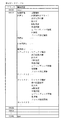
また、本実施形態のパチンコ機10における第1当たり種別カウンタC2の値は、0〜99の範囲のループカウンタとして構成されている。そして、図17(a)に示すように、この第1当たり種別カウンタC2において、乱数値が「0〜20」であった場合の大当たり種別は、「大当たりA」となり、値が「21〜50」であった場合の大当たり種別は、「大当たりB」となり、値が「51〜59」であった場合の大当たり種別は、「大当たりC」となり、値が「60〜80」であった場合の大当たり種別は、「大当たりD」となり、値が「81〜99」であった場合の大当たり種別は、「大当たりE」となる。
Further, the value of the first hit type counter C2 in the
このように、本実施形態のパチンコ機10は、第1当たり種別カウンタC2が示す乱数の値によって、5種類の当たり種別(大当たりA、大当たりB、大当たりC、大当たりD、大当たりE)が決定されるように構成されている。尚、第1当たり種別カウンタC2の値(乱数値)から、特別図柄の大当たり種別を決定するための乱数値は、特別図柄大当たり種別テーブル(図示せず)により設定されており、このテーブルは、主制御装置110のROM202内に設けられている。
Thus, in the
ここで、大当たりAは、奇数図柄で第3図柄停止表示されることで報知される当たりである。大当たりAでは、16ラウンドの特典遊技(特定入賞口65aが16回所定時間または所定個数の遊技球が入賞するまで開放される)が実行された後に、遊技状態が高確率遊技状態に設定される当たりである。
Here, the jackpot A is a hit that is notified when the third symbol is stopped and displayed with an odd symbol. In the jackpot A, after the 16-round bonus game (the specific winning
大当たりBは、バトル図柄が第3図柄表示装置81に停止表示されて実行される。この大当たりBは、16ラウンドの特典遊技で構成された16R確変特殊大当たりである。1ラウンドから2ラウンドまでは、後述する大当たりC、小当たりと同様に、短時間の開放時間(本実施形態では1秒)で複数回(本実施形態では、8回)開放して1ラウンドを構成する特殊開放が実行される。その後、大当たりAと同様の1ラウンドの開放時間で、3ラウンド〜16ラウンドまでが実行される。なお、1ラウンドから2ラウンドまでは、発射球数に対して、特定入賞口65aに入賞して払い出される賞球の方が少なくなるように設定されている。大当たり遊技後には、高確率遊技状態に設定される。なお、大当たりAとは異なり、普通図柄の確率は、通常確率のままであり、通常確率遊技状態と識別が困難に構成されている。
The jackpot B is executed with the battle symbol stopped and displayed on the third
大当たりCは、2ラウンド確変大当たりであり、大当たりBの1ラウンドから2ラウンドまでの大当たり遊技が実行される。この大当たりCも第3図柄表示装置81にバトル図柄が停止表示された場合に実行される。
The jackpot C is a two-round probability variable jackpot, and jackpot games from 1 to 2 rounds of the jackpot B are executed. This jackpot C is also executed when the battle symbol is stopped and displayed on the third
大当たりDは、16ラウンド通常大当たりであり、大当たりAと同様の大当たり遊技が実行され、偶数図柄の第3図柄が停止表示されることで報知される。なお、大当たり遊技後に、時短回数100回が設定されるが、大当たり確率は、低確率が設定される低確率遊技状態(通常遊技状態)が設定される。 The jackpot D is a normal jackpot for 16 rounds, and a jackpot game similar to the jackpot A is executed, and the third symbol of the even symbol is stopped and displayed. In addition, after the jackpot game, the number of time reductions is set to 100, but the jackpot probability is set to a low probability game state (normal game state) in which a low probability is set.
大当たりEは、16通常特殊大当たりであり、バトル図柄が第3図柄表示装置81に停止表示された後に実行される。大当たりAと同様の大当たり遊技が実行されるが、大当たり遊技後は、低確率遊技状態が設定される。なお、時短は付与されない。
The jackpot E is 16 special special jackpots, and is executed after the battle symbol is stopped and displayed on the third
小当たりは、当否判定結果が外れと判別されたもののうち、小当たりと判別された場合に実行される特典遊技であり、大当たりCと同様の1ラウンドから2ラウンドまでの特典遊技が実行される。この小当たりは、第3図柄表示装置81にバトル図柄が表示された場合または小当たり専用の第3図柄(本実施形態では「341」)が表示され、実行される。
The bonus game is a bonus game that is executed when it is determined that the jackpot is out of those determined to be out of play, and the bonus game from 1 to 2 rounds similar to the jackpot C is executed. . This small hit is executed when the battle symbol is displayed on the third
このように、本実施形態では、遊技者は、バトル図柄で停止表示された場合に実行される大当たり遊技の場合に、大当たりBであるか、大当たりEであるかを判別し難く構成されている。また。大当たりCと小当たりとについても判別が困難に構成されている。それぞれ、大当たり(小当たり)遊技後の遊技状態が高確率遊技状態か低確率遊技状態に移行するかの違いがあり、遊技者は、遊技状態が高確率遊技状態ではないかと期待して、実際は低確率遊技状態(大当たりEまたは小当たり後の遊技)であっても遊技を止めずに続けることができる。よって、遊技を長時間楽しんで行うことができる。 As described above, in the present embodiment, the player is configured to hardly determine whether the game is a jackpot B or a jackpot E in the case of a jackpot game that is executed when the game is stopped and displayed with a battle symbol. . Also. The big hit C and the small hit are also difficult to distinguish. Each of them has a difference in whether the gaming state after the big hit (small hit) game shifts to a high probability gaming state or a low probability gaming state, and the player expects that the gaming state is a high probability gaming state, in fact, Even in a low-probability gaming state (game after big hit E or small hit), the game can be continued without stopping. Therefore, the game can be enjoyed for a long time.
停止種別選択カウンタC3は、例えば0〜99の範囲内で順に1ずつ加算され、最大値(つまり99)に達した後0に戻る構成となっている。本実施形態では、停止種別選択カウンタC3によって、第3図柄表示装置81で表示される外れ時の停止種別が選択され、リーチが発生した後、最終停止図柄がリーチ図柄の前後に1つだけずれて停止する「前後外れリーチ」(例えば98,99)と、同じくリーチ発生した後、最終停止図柄がリーチ図柄の前後以外で停止する「前後外れ以外リーチ」(例えば90〜97の範囲)と、リーチ発生しない「完全外れ」(例えば0〜89の範囲)との3つの停止(演出)パターンが選択される。停止種別選択カウンタC3の値は、例えば定期的に(本実施形態ではタイマ割込処理毎に1回)更新され、球が第1入球口64に入賞したタイミングでRAM203の特別図柄保留球格納エリア203aに格納される。
For example, the stop type selection counter C3 is incremented by 1 within a range of 0 to 99, for example, and reaches a maximum value (that is, 99) and then returns to 0. In the present embodiment, the stop type at the time of release displayed on the third
尚、停止種別選択カウンタC3の値(乱数値)から、特別図柄の停止種別を決定するための乱数値は、停止種別選択テーブル(図示せず)により設定されており、このテーブルは、主制御装置110のROM202内に設けられている。また、本実施形態ではこのテーブルを、特別図柄の高確率時用と、特別図柄の低確率時用とに分けており、テーブルに応じて、外れの停止種別ごとに設定される乱数値の範囲を変えている。これは、パチンコ機10が特別図柄の高確率状態であるか、特別図柄の低確率状態であるか等に応じて、停止種別の選択比率を変更するためである。
The random value for determining the stop type of the special symbol from the value (random number value) of the stop type selection counter C3 is set by a stop type selection table (not shown). It is provided in the
例えば、高確率状態では、大当たりが発生し易いため必要以上にリーチ演出が選択されないように、「完全外れ」の停止種別に対応した乱数値の範囲が0〜89と広い高確率時用のテーブルが選択され、「完全外れ」が選択され易くなる。このテーブルは、「前後外れリーチ」が98,99と狭くなると共に「前後外れ以外リーチ」も90〜97と狭くなり、「前後外れリーチ」や「前後外れ以外リーチ」が選択され難くなる。また、低確率状態であれば、第1入球口64への球の入球時間を確保するために「完全外れ」の停止種別に対応した乱数値の範囲が0〜79と狭い低確率時用のテーブルが選択され、「完全外れ」が選択され難くなる。
For example, in a high-probability state, a table for a high-probability time with a wide range of random values from 0 to 89 corresponding to the stop type “completely out” is selected so that a reach effect is not selected more than necessary because a big hit is likely to occur. Is selected, and “completely off” is easily selected. In this table, the “front / rear detachment reach” is narrowed to 98,99, and the “reach other than front / rear detachment” is also narrowed to 90 to 97, making it difficult to select “rearward / rearward detachment reach” and “reach other than front / rear detachment”. In the low probability state, the random value range corresponding to the stop type “completely off” is 0 to 79 and the probability is low so as to secure the time for entering the ball into the
この停止種別選択テーブルは、「前後外れ以外リーチ」の停止種別に対応した乱数値の範囲が80〜97と広くなり、「前後外れ以外リーチ」が選択され易くなっている。よって、低確率状態では、演出時間の長いリーチ表示を多く行うことできるので、第1入球口64への球の入球時間を確保でき、第3図柄表示装置81による変動表示が継続して行われ易くなる。尚、後者のテーブルにおいても、「前後外れリーチ」の停止種別に対応した乱数値の範囲は98,99に設定される。
In this stop type selection table, the range of random values corresponding to the stop type of “reach other than front / rear out” is widened to 80 to 97, and “reach other than front / rear out” is easily selected. Therefore, in the low probability state, it is possible to perform a lot of reach display with a long production time, so it is possible to secure the time for entering the ball into the
変動種別カウンタCS1は、例えば0〜198の範囲内で順に1ずつ加算され、最大値(つまり198)に達した後0に戻る構成となっている。第1入球口64に遊技球が入球したタイミングで取得されて、主制御装置110のRAM203の特別図柄保留球格納エリア203aに格納される。変動種別カウンタCS1によって、いわゆるノーマルリーチ、スーパーリーチ等の大まかな表示態様が決定される。表示態様の決定は、具体的には、図柄変動の変動時間の決定である。変動種別カウンタCS1により決定された変動時間に基づいて、音声ランプ制御装置113や表示制御装置114により第3図柄表示装置81で表示される第3図柄のリーチ種別や細かな図柄変動態様が決定される。変動種別カウンタCS1の値は、後述するメイン処理(図32参照)が1回実行される毎に1回更新され、当該メイン処理内の残余時間内でも繰り返し更新される。尚、変動種別カウンタCS1の値(乱数値)から、図柄変動の変動時間を一つ決定する乱数値を格納した変動パターン選択テーブル(図18参照)は、主制御装置110のROM202内に設けられている。
The variation type counter CS1 is, for example, incremented by 1 within a range of 0 to 198, and returns to 0 after reaching the maximum value (that is, 198). It is acquired at the timing when a game ball enters the
変動パターンテーブル202bには、図18に示すように、当たり用の変動パターンとして、保留個数に関わらず、大当たりA、D専用の「ノーマル大当たり変動パターン(ノーマルリーチ当たり)」各種、「スーパーリーチ変動パターン」各種、大当たりB専用の「特殊大当たり変動パターンB」各種、大当たりC専用の「特殊大当たり変動パターンC」各種がそれぞれ設定されている。また、外れ用の変動パターンとして、保留個数0個〜2個と3個〜4個の別に、「短時間外れ変動パターン(短時間用)」、「長時間外れ変動パターン(長時間用)」、「ノーマルリーチ外れ変動パターン」各種、「スーパーリーチ外れ変動パターン」各種が規定されている。また、小当たり専用の変動パターンとして「小当たり専用変動パターン」各種が規定されている。そして、変動パターン選択テーブル202bに規定された各種変動パターンから、予測された抽選結果や、予測された停止種別(大当たりの場合には大当たり種別)に応じて変動パターンが選定される。
As shown in FIG. 18, the variation pattern table 202b includes various “normal jackpot variation patterns (per normal reach)” dedicated to jackpots A and D, “super reach variation patterns”, regardless of the number of reserves. "Various types of" Special jackpot fluctuation pattern B "dedicated to jackpot B and" Special jackpot fluctuation pattern C "dedicated to jackpot C are set. In addition, as a variation pattern for detachment, “short-time detachment variation pattern (for a short time)” and “long-time detachment variation pattern (for a long time)”, in addition to the holding
第2当たり乱数カウンタC4は、例えば0〜239の範囲内で順に1ずつ加算され、最大値(つまり239)に達した後0に戻るループカウンタとして構成されている。また、第2当たり乱数カウンタC4が1周した場合、その時点の第2初期値乱数カウンタCINI2の値が当該第2当たり乱数カウンタC4の初期値として読み込まれる。第2当たり乱数カウンタC4の値は、本実施形態ではタイマ割込処理毎に、例えば定期的に更新され、球が左右何れかの第2入球口(スルーゲート)67を通過したことが検知された時に取得され、RAM203の普通図柄保留球格納エリア203bに格納される。
The second random number counter C4 is configured as a loop counter that is incremented one by one within a range of, for example, 0 to 239 and returns to 0 after reaching the maximum value (that is, 239). Further, when the second random number counter C4 makes one round, the value of the second initial value random number counter CINI2 at that time is read as the initial value of the second random number counter C4. In this embodiment, the value of the second per-random number counter C4 is periodically updated, for example, every timer interrupt process, and it is detected that the ball has passed through either the left or right second entrance (through gate) 67. And is stored in the normal symbol holding
そして、普通図柄の当たりとなる乱数の値は、主制御装置のROM202に格納される普通図柄当たり乱数テーブル(図示せず)によって設定されており、第2当たり乱数カウンタC4の値が、普通図柄当たり乱数テーブルによって設定された当たりとなる乱数の値と一致する場合に、普通図柄の当たりと判定する。また、この普通図柄当たり乱数テーブルは、普通図柄の低確率時(普通図柄の通常状態である期間)用と、その低確率時より普通図柄の当たりとなる確率の高い高確率時(普通図柄の時短状態である期間)用との2種類に分けられ、それぞれに含まれる大当たりとなる乱数の個数が異なって設定されている。このように、当たりとなる乱数の個数を異ならせることにより、普通図柄の低確率時と普通図柄の高確率時とで、当たりとなる確率が変更される。
The value of the random number that becomes the normal symbol is set by a random number table (not shown) per normal symbol stored in the
図17(b)に示すように、普通図柄の低確率時に、普通図柄の当たりとなる乱数値は24個あり、その範囲は「5〜28」となっている。これら乱数値は、低確率時用の普通図柄当たり乱数テーブルに格納されている。このように普通図柄の低確率時には、乱数値の総数が240ある中で、大当たりとなる乱数値の総数が24なので、特別図柄の大当たりとなる確率は、「1/10」となる。 As shown in FIG. 17 (b), there are 24 random numbers that are hit by the normal symbol at the low probability of the normal symbol, and the range is “5-28”. These random values are stored in a random table per normal symbol for low probability. Thus, when the probability of a normal symbol is low, the total number of random numbers that are jackpots is 24 among the total number of random number values, and therefore the probability of jacking a special symbol is “1/10”.
パチンコ機10が普通図柄の低確率時である場合に、球が第2入球口67を通過すると、第2当たり乱数カウンタC4の値が取得されると共に、第2図柄表示装置83において普通図柄の変動表示が30秒間実行される。そして、取得された第2当たり乱数カウンタC4の値が「5〜28」の範囲であれば当選と判定されて、第2図柄表示装置83における変動表示が終了した後に、停止図柄(第2図柄)として「○」の図柄が点灯表示されると共に、第1入球口64が「0.2秒間×1回」だけ開放される。尚、本実施形態では、パチンコ機10が普通図柄の低確率時である場合に、普通図柄の当たりとなったら第1入球口64が「0.2秒間×1回」だけ開放されるが、開放時間や回数は任意に設定すれば良い。例えば、「0.5秒間×2回」開放しても良い。
When the
一方で、普通図柄の高確率時に、普通図柄の大当たりとなる乱数値は200個あり、その範囲は「5〜204」となっている。これらの乱数値は、高確率時用の普通図柄当たり乱数テーブルに格納されている。このように特別図柄の低確率時には、乱数値の総数が240ある中で、大当たりとなる乱数値の総数が200なので、特別図柄の大当たりとなる確率は、「1/1.2」となる。 On the other hand, when there is a high probability of a normal symbol, there are 200 random values that are jackpots of the normal symbol, and the range is “5-204”. These random values are stored in a random table per normal symbol for high probability. Thus, when the special symbol has a low probability, the total number of random numbers that are jackpots is 200 among the total number of random number values, and therefore, the probability that the special symbol is jackpot is “1 / 1.2”.
パチンコ機10が普通図柄の高確率時である場合に、球が第2入球口67を通過すると、第2当たり乱数カウンタC4の値が取得されると共に、第2図柄表示装置83において普通図柄の変動表示が3秒間実行される。そして、取得された第2当たり乱数カウンタC4の値が「5〜204」の範囲であれば当選と判定されて、第2図柄表示装置83における変動表示が終了した後に、停止図柄(第2図柄)として「○」の図柄が点灯表示されると共に、第1入球口64が「1秒間×2回」開放される。このように、普通図柄の高確率時には、普通図柄の低確率時と比較して、変動表示の時間が「30秒→3秒」と非常に短くなり、更に、第1入球口64の解放期間が「0.2秒×1回→1秒間×2回」と非常に長くなるので、第1入球口64へ球が入球し易い状態となる。尚、第2当たり乱数カウンタC4の値(乱数値)から、普通図柄の当たりか否かを判定する乱数値を格納したテーブル(図示せず)は、ROM202内に設けられている。尚、本実施形態では、パチンコ機10が普通図柄の高確率時である場合に、普通図柄の当たりとなったら第1入球口64が「1秒間×2回」だけ開放されるが、開放時間や回数は任意に設定すれば良い。例えば、「3秒間×3回」開放しても良い。
When the
第2初期値乱数カウンタCINI2は、第2当たり乱数カウンタC4と同一範囲で更新されるループカウンタとして構成され(値=0〜239)、タイマ割込処理(図25参照)毎に1回更新されると共に、メイン処理(図32参照)の残余時間内で繰り返し更新される。 The second initial value random number counter CINI2 is configured as a loop counter that is updated in the same range as the second random number counter C4 (value = 0 to 239), and is updated once every timer interrupt process (see FIG. 25). And repeatedly updated within the remaining time of the main process (see FIG. 32).
このように、RAM203には種々のカウンタ等が設けられており、主制御装置110では、このカウンタ等の値に応じて大当たり抽選や第1図柄表示装置37および第3図柄表示装置81における表示の設定、第2図柄表示装置83における表示結果の抽選といったパチンコ機10の主要な処理を実行することができる。
As described above, the
図15に戻り、説明を続ける。RAM203は、図16に図示した各種カウンタのほか、MPU201の内部レジスタの内容やMPU201により実行される制御プログラムの戻り先番地などが記憶されるスタックエリアと、各種のフラグおよびカウンタ、I/O等の値が記憶される作業エリア(作業領域)とを有している。
Returning to FIG. 15, the description will be continued. In addition to the various counters shown in FIG. 16, the
なお、RAM203は、パチンコ機10の電源の遮断後においても電源装置115からバックアップ電圧が供給されてデータを保持(バックアップ)できる構成となっており、RAM203に記憶されるデータは、すべてバックアップされる。
Note that the
停電などの発生により電源が遮断されると、その電源遮断時(停電発生時を含む。以下同様)のスタックポインタや、各レジスタの値がRAM203に記憶される。一方、電源投入時(停電解消による電源投入を含む。以下同様)には、RAM203に記憶される情報に基づいて、パチンコ機10の状態が電源遮断前の状態に復帰される。RAM203への書き込みはメイン処理(図32参照)によって電源遮断時に実行され、RAM203に書き込まれた各値の復帰は電源投入時の立ち上げ処理(図31参照)において実行される。なお、MPU201のNMI端子(ノンマスカブル割込端子)には、停電等の発生による電源遮断時に、停電監視回路252からの停電信号SG1が入力されるように構成されており、その停電信号SG1がMPU201へ入力されると、停電時処理としてのNMI割込処理(図30(b)参照)が即座に実行される。
When the power is shut down due to the occurrence of a power failure or the like, the stack pointer and the value of each register when the power is shut off (including when the power failure occurs, the same applies hereinafter) are stored in the
また、RAM203は、図15に示すように、特別図柄保留球格納エリア203aと、普通図柄保留球格納エリア203bと、特別図柄保留球数カウンタ203cと、普通図柄保留球数カウンタ203dと、時短中カウンタ203eと、その他メモリエリア203zとを有している。
As shown in FIG. 15, the
特別図柄保留球格納エリア203aは、1つの実行エリアと、4つの保留エリア(保留第1エリア〜保留第4エリア)とを有しており、これらの各エリアには、第1当たり乱数カウンタC1、第1当たり種別カウンタC2、及び停止種別選択カウンタC3の各値がそれぞれ格納される。
The special symbol holding
より具体的には、球が第1入球口64へ入賞(始動入賞)したタイミングで、各カウンタC1〜C3、CS1の各値が取得され、その取得されたデータが、4つの保留エリア(保留第1エリア〜保留第4エリア)の空いているエリアの中で、エリア番号(第1〜第4)の小さいエリアから順番に記憶される。つまり、エリア番号の小さいエリアほど、時間的に古い入賞に対応するデータが記憶され、保留第1エリアには、時間的に最も古い入賞に対応するデータが記憶される。尚、4つの保留エリアの全てにデータが記憶されている場合には、新たに何も記憶されない。
More specifically, each value of each of the counters C1 to C3 and CS1 is acquired at the timing when the ball wins (start winning) at the
その後、主制御装置110において、特別図柄の抽選が行われる場合には、特別図柄保留球格納エリア203aの保留第1エリアに記憶されている各カウンタC1〜C3、CS1の各値が、実行エリアへシフトされ(移動させられ)、その実行エリアに記憶された各カウンタC1〜C3、CS1の各値に基づいて、特別図柄の抽選などの判定が行われる。
Thereafter, when the special controller lottery is performed in the
尚、保留第1エリアから実行エリアへデータをシフトすると、保留第1エリアが空き状態となる。そこで、他の保留エリア(保留第2エリア〜保留第4エリア)に記憶されている入賞のデータを、エリア番号の1小さい保留エリア(保留第1エリア〜保留第3エリア)に詰めるシフト処理が行われる。本実施形態では、特別図柄保留球格納エリア203aにおいて、入賞のデータが記憶されている保留エリア(第2保留エリア〜第4保留エリア)についてのみデータのシフトが行われる。
Note that when the data is shifted from the reserved first area to the execution area, the reserved first area becomes empty. Therefore, a shift process is performed in which winning data stored in other reserved areas (holding second area to holding fourth area) is packed into a holding area having a smaller area number (holding first area to holding third area). Done. In the present embodiment, in the special symbol reserved
本パチンコ機10では、球が第1入球口64へ入賞(始動入賞)し、その始動入賞に応じて各カウンタC1〜C3、CS1の各値が取得されると直ちに、本来の特別図柄の大当たり抽選とは別に、その取得された各カウンタC1〜C3の各値から、本来の抽選が行われた場合に得られる各種情報が予測(推定)される。このように、本来の特別図柄の抽選が行われる前に、始動入賞に対応するデータ(各カウンタC1〜C3、CS1の各値)に基づいて、本来の抽選が行われた場合に得られる各種情報を予測することを、以後、特別図柄の抽選結果を先読みすると記載する。なお、各種情報としては、当否、停止種別、変動パターンなどが該当する。
In the
そして、先読みが終了すると、先読みにより得られた各種情報(当否、停止種別、変動パターン)を含む入賞情報コマンドが音声ランプ制御装置113へ送信される。入賞情報コマンドが音声ランプ制御装置113によって受信されると、音声ランプ制御装置113は、入賞情報コマンドから、当否、停止種別、および変動パターンを抽出し、それらを入賞情報としてRAM233の入賞情報格納エリア223aに格納する。
When the prefetching is completed, a winning information command including various types of information (presence / absence, stop type, variation pattern) obtained by the prefetching is transmitted to the sound
なお、特別図柄保留球格納エリア203aには、後述する主制御装置110のMPU201により実行される始動入賞処理(図28のS105)のS407により判定された当否判定結果(先読み判定の結果)も保留第1〜第4エリアにそれぞれ記憶される。
In addition, the special symbol reservation
普通図柄保留球格納エリア203bは、特別図柄保留球格納エリア203aと同様に、1つの実行エリアと、4つの保留エリア(保留第1エリア〜保留第4エリア)とを有している。これらの各エリアには、第2当たり乱数カウンタC4が格納される。
Similarly to the special symbol reserved
より具体的には、球が左右何れかの第2入球口67を通過したタイミングで、カウンタC4の値が取得され、その取得されたデータが、4つの保留エリア(保留第1エリア〜保留第4エリア)の空いているエリアの中で、エリア番号(第1〜第4)の小さいエリアから順番に記憶される。つまり、特別図柄保留球格納エリア203aと同様に、入賞した順序が保持されつつ、入賞に対応するデータが格納される。尚、4つの保留エリアの全てにデータが記憶されている場合には、新たに何も記憶されない。
More specifically, the value of the counter C4 is acquired at the timing when the ball passes through the left or right
その後、主制御装置110において、普通図柄の当たりの抽選が行われる場合には、普通図柄保留球格納エリア203bの保留第1エリアに記憶されているカウンタC4の値が、実行エリアへシフトされ(移動させられ)、その実行エリアに記憶されたカウンタC4の値に基づいて、普通図柄の当たりの抽選などの判定が行われる。
Thereafter, when the
尚、保留第1エリアから実行エリアへデータをシフトすると、保留第1エリアが空き状態となるので、特別図柄保留球格納エリア203aの場合と同様に、他の保留エリアに記憶されている入賞のデータを、エリア番号の1小さい保留エリアに詰めるシフト処理が行われる。また、データのシフトも、入賞のデータが記憶されている保留エリアについてのみ行われる。
When the data is shifted from the reserved first area to the execution area, the reserved first area becomes empty, and as in the case of the special symbol reserved
特別図柄保留球数カウンタ203cは、第1入球口64への入球(始動入賞)に基づいて第1図柄表示装置37で行われる特別図柄(第1図柄)の変動表示(第3図柄表示装置81で行われる変動表示)の保留球数(待機回数)を最大4回まで計数するカウンタである。この特別図柄保留球数カウンタ203cは、初期値がゼロに設定されており、第1入球口64へ球が入球して変動表示の保留球数が増加する毎に、最大値4まで1加算される(図16のS404参照)。一方、特別図柄保留球数カウンタ203cは、新たに特別図柄の変動表示が実行される毎に、1減算される(図26のS205参照)。
The special symbol reserved
この特別図柄保留球数カウンタ203cの値(特別図柄における変動表示の保留回数N)は、保留球数コマンドによって音声ランプ制御装置113に通知される(図26のS206、図28のS405参照)。保留球数コマンドは、特別図柄保留球数カウンタ203cの値が変更される度に、主制御装置110から音声ランプ制御装置113に対して送信されるコマンドである。
The value of the special symbol hold
音声ランプ制御装置113は、特別図柄保留球数カウンタ203cの値が変更される度に、主制御装置110より送信される保留球数コマンドによって、主制御装置110に保留された変動表示の保留球数そのものの値を取得することができる。これにより、音声ランプ制御装置113の特別図柄保留球数カウンタ223bによって管理される変動表示の保留球数が、ノイズ等の影響によって、主制御装置110に保留された実際の変動表示の保留球数からずれてしまった場合であっても、次に受信する保留球数コマンドによって、そのずれを修正することができる。
The voice
尚、音声ランプ制御装置113は、保留球数コマンドに基づいて保留球数を管理し、保留球数が変化する度に表示制御装置114に対して、保留球数を通知するための表示用保留球数コマンド、表示用保留図柄コマンドを送信する。
The voice
普通図柄保留球数カウンタ203dは、第2入球口67における球の通過に基づいて第2図柄表示装置83で行われる普通図柄(第2図柄)の変動表示の保留球数(待機回数)を最大4回まで計数するカウンタである。この普通図柄保留球数カウンタ203dは、初期値がゼロに設定されており、球が第2入球口67を通過して変動表示の保留球数が増加する毎に、最大値4まで1加算される(図30(a)のS704参照)。一方、普通図柄保留球数カウンタ203dは、新たに普通図柄(第2図柄)の変動表示が実行される毎に、1減算される(図29のS605参照)。
The normal symbol reserved ball number counter 203d displays the number of held balls (the number of waiting times) of the variable symbol display of the normal symbol (second symbol) performed by the second
球が左右何れかの第2入球口67を通過した場合に、この普通図柄保留球数カウンタ203dの値(普通図柄における変動表示の保留回数M)が4未満であれば、第2当たり乱数カウンタC4の値が取得され、その取得されたデータが、普通図柄保留球格納エリア203bに記憶される(図30(a)のS705)。一方、球が左右何れかの第2入球口67を通過した場合に、この普通図柄保留球数カウンタ203dの値が4であれば、普通図柄保留球格納エリア203bには新たに何も記憶されない(図30(a)のS703:No)。
If the value of the normal symbol reserved ball number counter 203d (the number M of the variable display hold in the normal symbol) is less than 4 when the ball passes through the left or right
時短中カウンタ203eは、パチンコ機10が普通図柄の時短状態であるか否かを示すカウンタであり、時短中カウンタ203eの値が1以上であれば、パチンコ機10が普通図柄の時短状態であることを示し、時短中カウンタ203eの値が0であれば、パチンコ機10が普通図柄の通常状態であることを示す。この時短中カウンタ203eは、初期値がゼロに設定されており、主制御装置110において特別図柄の抽選が行われ、特別図柄の大当たりと判定される度に、その大当たり種別に応じた値が設定される。即ち、特別図柄の大当たりになった場合には、時短中カウンタ203eの値が幾つであるかに関わらず、大当たり種別に応じた値が新たに設定される。
The hour /
具体的には、「大当たりD」であると判定されると100に設定される(図26のS214参照)。その後、時短中カウンタ203eの値が0になるまで、特別図柄の変動演出が終了する毎に1が減算される(図26のS217)。
Specifically, when it is determined that the jackpot is D, it is set to 100 (see S214 in FIG. 26). Thereafter, 1 is subtracted every time the special symbol variation effect is ended until the value of the hour /
普通図柄の当たりの抽選が行われる場合には、時短中カウンタ203eの値が参照され、その値が1以上であれば、高確率時用の普通図柄当たり乱数テーブルに基づいて、普通図柄の抽選が行われる一方、時短中カウンタ203eの値が0であれば、低確率時用の普通図柄当たり乱数テーブルに基づいて、普通図柄の抽選が行われる(図29のS610,S611参照)。
When the normal symbol winning lottery is performed, the value of the hour and
その他メモリエリア203zは、主制御装置110のMPU201がパチンコ機10の制御で必要なその他の各種フラグやデータ等が記憶されるエリアである。
The other memory area 203z is an area for storing various other flags and data necessary for the
主制御装置110のMPU201には、アドレスバス及びデータバスで構成されるバスライン204を介して入出力ポート205が接続されている。入出力ポート205には、払出制御装置111、音声ランプ制御装置113、第1図柄表示装置37、第2図柄表示装置83、第2図柄保留ランプ84、特定入賞口65aの開閉板の下辺を軸として前方側に開閉駆動するための大開放口ソレノイドや電動役物を駆動するためのソレノイドなどからなるソレノイド209が接続され、MPU201は、入出力ポート205を介してこれらに対し各種コマンドや制御信号を送信する。
An input /
また、入出力ポート205には、図示しないスイッチ群やセンサ群などからなる各種スイッチ208や、電源装置115に設けられた後述のRAM消去スイッチ回路253が接続され、MPU201は各種スイッチ208から出力される信号や、RAM消去スイッチ回路253より出力されるRAM消去信号SG2に基づいて各種処理を実行する。
The input /
払出制御装置111は、払出モータ216を駆動させて賞球や貸出球の払出制御を行うものである。演算装置であるMPU211は、そのMPU211により実行される制御プログラムや固定値データ等を記憶したROM212と、ワークメモリ等として使用されるRAM213とを有している。
The
払出制御装置111のRAM213は、主制御装置110のRAM203と同様に、MPU211の内部レジスタの内容やMPU211により実行される制御プログラムの戻り先番地などが記憶されるスタックエリアと、各種のフラグおよびカウンタ、I/O等の値が記憶される作業エリア(作業領域)とを有している。RAM213は、パチンコ機10の電源の遮断後においても電源装置115からバックアップ電圧が供給されてデータを保持(バックアップ)できる構成となっており、RAM213に記憶されるデータは、すべてバックアップされる。なお、主制御装置110のMPU201と同様、MPU211のNMI端子にも、停電等の発生による電源遮断時に停電監視回路252から停電信号SG1が入力されるように構成されており、その停電信号SG1がMPU211へ入力されると、停電時処理としてのNMI割込処理(図30(b)参照)が即座に実行される。
The
払出制御装置111のMPU211には、アドレスバス及びデータバスで構成されるバスライン214を介して入出力ポート215が接続されている。入出力ポート215には、主制御装置110や払出モータ216、発射制御装置112などがそれぞれ接続されている。また、図示はしないが、払出制御装置111には、払い出された賞球を検出するための賞球検出スイッチが接続されている。なお、該賞球検出スイッチは、払出制御装置111に接続されるが、主制御装置110には接続されていない。
An input /
発射制御装置112は、主制御装置110により球の発射の指示がなされた場合に、操作ハンドル51の回転操作量に応じた球の打ち出し強さとなるよう球発射ユニット112aを制御するものである。球発射ユニット112aは、図示しない発射ソレノイドおよび電磁石を備えており、その発射ソレノイドおよび電磁石は、所定条件が整っている場合に駆動が許可される。具体的には、遊技者が操作ハンドル51に触れていることをタッチセンサ51aにより検出し、球の発射を停止させるための打ち止めスイッチ51bがオフ(操作されていないこと)を条件に、操作ハンドル51の回動量に対応して発射ソレノイドが励磁され、操作ハンドル51の操作量に応じた強さで球が発射される。
The
<音声ランプ制御装置113の電気的構成>
音声ランプ制御装置113は、音声出力装置(図示しないスピーカなど)226における音声の出力、ランプ表示装置(電飾部29〜33、表示ランプ34など)227における点灯および消灯の出力、変動演出(変動表示)といった表示制御装置114で行われる第3図柄表示装置81の表示態様の設定などを制御するものである。演算装置であるMPU221は、そのMPU221により実行される制御プログラムや固定値データ等を記憶したROM222と、ワークメモリ等として使用されるRAM223とを有している。
<Electrical Configuration of Audio
The sound
音声ランプ制御装置113のMPU221には、アドレスバス及びデータバスで構成されるバスライン224を介して入出力ポート225が接続されている。入出力ポート225には、主制御装置110、表示制御装置114、音声出力装置226、ランプ表示装置227、枠ボタン22などがそれぞれ接続されている。
An input /
音声ランプ制御装置113は、枠ボタン22からの入力を監視し、遊技者によって枠ボタン22が操作された場合は、第3図柄表示装置81で表示されるステージを変更したり、スーパーリーチ時の演出内容を変更したりするように、音声出力装置226、ランプ表示装置227を制御し、また、表示制御装置114へ指示する。ステージが変更される場合は、変更後のステージに応じた背面画像を第3図柄表示装置81に表示させるべく、変更後のステージに関する情報を含めた背面画像変更コマンドを表示制御装置114へ送信する。ここで、背面画像とは、第3図柄表示装置81に表示させる主要な画像である第3図柄の背面側に表示される画像のことである。
The voice
音声ランプ制御装置113は、主制御装置110からのコマンドや、音声ランプ制御装置113に接続された各種装置等の状況に応じてエラーを判定し、そのエラーの種別を含めてエラーコマンドを表示制御装置114へ送信する。表示制御装置114では、受信したエラーコマンドによって示されるエラー種別(例えば、振動エラー)に応じたエラーメッセージ画像を第3図柄表示装置81に遅滞無く表示させる制御が行われる。
The sound
音声ランプ制御装置113のMPU221のROM222には、各種制御に必要な制御プログラムや、各種データ等が記憶されている。その一部として挙げると、図17(d)に示すように、先読み抽選テーブル222a、先読み回数決定テーブル222b、保留図柄選択テーブル222c、変動パターンデータ222dがそれぞれ設定されている。
The
先読み抽選テーブル222aは、図19(a)に示すように、先読みあり、先読みなしを音声ランプ制御装置113が受信した入賞コマンドの当否判定結果、保留球数、演出カウンタ223iの値に基づいて決定するための抽選テーブルである。先読みは、音声ランプ制御装置113のMPU221が主制御装置110のMPU201の特別図柄保留球数格納エリア203aに格納されている保留球の当否判定結果を変動開始前に入賞コマンドに基づいて判別して、その当否判定結果に基づく演出表示態様を決定して、その当否判定結果を報知する第3図柄が変動開始となる前に、所定の演出を行うための制御処理である。
As shown in FIG. 19A, the pre-read lottery table 222a is determined based on the result of determining whether or not the winning command has been received by the voice
なお、この先読み抽選テーブル222a(図19(a)参照)は、音声ランプ制御装置113のMPU221が実行する先読み抽選処理(図39、S1412)のS1513の処理において参照される。
The prefetch lottery table 222a (see FIG. 19A) is referred to in the process of S1513 of the prefetch lottery process (FIG. 39, S1412) executed by the
先読み回数決定テーブル222bは、先読み抽選テーブル222a(図19(a)参照)より先読みありと判別された場合に、その先読み回数(先読みする保留球数の数)を決定するための抽選テーブルである。この先読み回数決定テーブル222bは、図19(b)に示すように、外れである場合に参照され、現在の保留球数に対応して、それぞれ演出カウンタ223iの値が先読み回数別に割り付けされている。これにより、保留球数内で、先読み回数を選択できるように構成されている。なお、先読み回数が大きいほど、選択され難く構成されている。なお、当たりを示す入賞コマンドを受信した場合には、その時の保留球数すべて(当たりとなる保留まで)で、先読み回数が決定される。即ち、大当たりとなる保留が先読み回数の最後の変動する保留球となる。よって、先読み演出(本実施形態では、ミッション演出等)の最後の変動で大当たりとさせることができ、遊技者に先読み演出が実行されることで、大当たりとなり易いように感じさせることができる。
The pre-reading number determination table 222b is a lottery table for determining the number of pre-reading (the number of reserved balls to be pre-read) when it is determined that there is pre-reading from the pre-reading lottery table 222a (see FIG. 19A). . As shown in FIG. 19B, the pre-reading number determination table 222b is referred to when it is off, and the value of the
なお、音声ランプ制御装置113のMPU221のROM222には、その他、主制御装置110により選択される変動パターンの種類のデータや、各種遊技に必要なデータが記憶されている。
In addition, the
音声ランプ制御装置113のRAM223には、入賞情報格納エリア223aと、特別図柄保留球数カウンタ223bと、変動開始フラグ223cと、停止種別選択フラグ223dと、先読み演出フラグ223eと、先読み開始フラグ223fと、先読み回数カウンタ記憶エリア223gと、歌詞表示カウンタ223hと、演出カウンタ223iと、その他メモリエリア223zとが少なくとも設けられている。
In the
入賞情報格納エリア223aは、1つの実行エリアと、4つのエリア(第1エリア〜第4エリア)とを有しており、これらの各エリアには、入賞情報がそれぞれ格納される。本パチンコ機10では、主制御装置110において始動入賞となった場合に、その始動入賞に応じて取得された第1当たり乱数カウンタC1、第1当たり種別カウンタC2及び停止種別選択カウンタC3の各値から、その始動入賞に対応する特別図柄の抽選が行われた場合に得られる各種情報(当否、停止種別、変動パターン)が主制御装置110において予測(推定)され、その予測された各種情報が、主制御装置110から音声ランプ制御装置113へ入賞情報コマンドによって通知される。
The winning
音声ランプ制御装置113では、入賞情報コマンドが受信されると、その入賞情報コマンドにより通知された各種情報(当否、停止種別、変動パターン)が入賞情報として抽出されて、その入賞情報が、入賞情報格納エリア223aに記憶される。より具体的には、抽出された入賞情報が、4つのエリア(第1エリア〜第4エリア)の空いているエリアの中で、エリア番号(第1〜第4)の小さいエリアから順番に記憶される。つまり、エリア番号の小さいエリアほど、時間的に古い入賞に対応するデータが記憶され、第1エリアには、時間的に最も古い入賞に対応するデータが記憶される。
When the winning information command is received, the sound
特別図柄保留球数カウンタ223bは、主制御装置110の特別図柄保留球数カウンタ203cと同様に、第1図柄表示装置37(および第3図柄表示装置81)で行われる変動演出(変動表示)であって、主制御装置110において保留されている変動演出の保留球数(待機回数)を最大4回まで計数するカウンタである。
The special symbol reserved
上述したように、音声ランプ制御装置113は、主制御装置110に直接アクセスして、主制御装置110のRAM203に格納されている特別図柄保留球数カウンタ203cの値を取得することができない。よって、音声ランプ制御装置113では、主制御装置110から送信される保留球数コマンドに基づいて保留球数をカウントし、特別図柄保留球数カウンタ223bにて、その保留球数を管理するようになっている。
As described above, the sound
具体的には、主制御装置110では、第1入球口64への入球によって変動表示の保留球数が加算された場合、又は、主制御装置110において特別図柄における変動表示が実行されて保留球数が減算された場合に、加算後または減算後の特別図柄保留球数カウンタ203cの値を示す保留球数コマンドを、音声ランプ制御装置113へ送信する。
Specifically, in the
音声ランプ制御装置113は、主制御装置110より送信される保留球数コマンドを受信すると、その保留球数コマンドから、主制御装置110の特別図柄保留球数カウンタ203cの値を取得して、特別図柄保留球数カウンタ223bに格納する(図37のS1409,S1412参照)。このように、音声ランプ制御装置113では、主制御装置110より送信される保留球数コマンドに従って、特別図柄保留球数カウンタ223bの値を更新するので、主制御装置110の特別図柄保留球数カウンタ203cと同期させながら、その値を更新することができる。
When the voice
特別図柄保留球数カウンタ223bの値は、第3図柄表示装置81における保留球数図柄の表示に用いられる。即ち、音声ランプ制御装置113は、保留球数コマンドの受信に応じて、そのコマンドにより示される保留球数を特別図柄保留球数カウンタ223bに格納すると共に、格納後の特別図柄保留球数カウンタ223bの値を表示制御装置114に通知するべく、表示用保留球数コマンドを表示制御装置114に対して送信する。
The value of the special symbol reserved
変動開始フラグ223cは、主制御装置110から送信される変動パターンコマンドを受信した場合にオンに設定され(図37のS1402参照)、第3図柄表示装置81における変動表示の設定がなされるときにオフに設定される(図40のS1602参照)。変動開始フラグ223cがオンになると、受信した変動パターンコマンドから抽出された変動パターンに基づいて、表示用変動パターンコマンドが設定される。
The
ここで設定された表示用変動パターンコマンドは、RAM223に設けられたコマンド送信用のリングバッファに記憶され、MPU221により実行されるメイン処理(図36参照)のコマンド出力処理(S1302)の中で、表示制御装置114に向けて送信される。表示制御装置114では、この表示用変動パターンコマンドを受信することによって、この表示用変動パターンコマンドによって示される変動パターンで、第3図柄表示装置81において第3図柄の変動表示が行われるように、その変動演出の表示制御が開始される。
The display variation pattern command set here is stored in the command transmission ring buffer provided in the
停止種別選択フラグ223dは、主制御装置110から送信される停止種別コマンドを受信した場合にオンに設定され(図37のS1406参照)、第3図柄表示装置81における停止種別の設定がなされるときにオフに設定される(図40のS1605参照)。
The stop
先読み演出フラグ223eは、先読み演出を実行することが決定されているかを判別するためのフラグである。この先読み演出フラグ223eは、音声ランプ制御装置113のMPU221により実行される先読み抽選処理(図39、S1412)のS1515の処理でオンに設定される。一方、S1508の処理において、後述する先読み回数カウンタが初期化されるのに基づいて、先読み演出フラグ223eもオフに設定される。
The
先読み開始フラグ223fは、先読み演出が開始されることを示すフラグである。この先読み開始フラグ223fは、音声ランプ制御装置113のMPU221により実行される先読み抽選処理(図39、S1412)のS1517の処理においてオンに設定される。一方、先読み演出選択処理(図38、S1404)のS1503の処理でオフに設定される。
The
先読み回数カウンタ記憶エリア223gは、先読み回数をカウントするための記憶エリアである。ここに記憶される値を先読み回数カウンタという。この先読み回数カウンタ記憶エリア223gには、音声ランプ制御装置113のMPU221により実行される先読み抽選処理(図39、S1412)のS1516の処理において、先読み回数決定テーブルより先読み回数が決定され記憶される。一方、先読み演出選択処理(図38、S1404)のS1506の処理が実行される毎に、1ずつ減算されて更新され、値が0となると(S1507:Yes)、S1508の処理において、初期値である0に初期化される。
The prefetch count
歌詞表示カウンタ223hは、第3図柄表示装置81に歌詞を表示するための、表示する歌詞データを決定するためのカウンタである。この歌詞表示カウンタ223hは、対応する音楽データの再生が開始されることに基づいて更新開始される。具体的には、音声ランプ制御装置113のMPU221により実行される音編集・出力処理(図41、S1309)のS1703の処理で再生する音楽データの長さに合わせた上限値に設定される。また、S1705の処理で経過時間に対応して1ずつ加算されて更新される。一方、S1714の処理において、初期値である0にリセットされる。
The
演出カウンタ223iは、0〜199までの範囲で繰り返し更新されるカウンタである。この演出カウンタ223iは、保留図柄の選択や、保留図柄抽選等で使用されるカウンタである。なお、この演出カウンタ223iは、音声ランプ制御装置113のMPU221により実行されるメイン処理において繰り返し更新される。
The
RAM223は、その他、主制御装置110より受信したコマンドを、そのコマンドに対応した処理が行われるまで一時的に記憶するその他記憶エリア223zを有している。なお、コマンド記憶領域はリングバッファで構成され、FIFO(First In First Out)方式によってデータの読み書きが行われる。音声ランプ処理装置113のコマンド判定処理(図37参照)が実行されると、コマンド記憶領域に記憶された未処理のコマンドのうち、最初に格納されたコマンドが読み出され、コマンド判定処理によって、そのコマンドが解析されて、そのコマンドに応じた処理が行われる。
In addition, the
表示制御装置114は、音声ランプ制御装置113及び第3図柄表示装置81が接続され、音声ランプ制御装置113より受信したコマンドに基づいて、第3図柄表示装置81における第3図柄の変動表示(変動演出)を制御するものである。この表示制御装置114の詳細については、図20を参照して後述する。
The
電源装置115は、パチンコ機10の各部に電源を供給するための電源部251と、停電等による電源遮断を監視する停電監視回路252と、RAM消去スイッチ122(図3参照)が設けられたRAM消去スイッチ回路253とを有している。電源部251は、図示しない電源経路を通じて、各制御装置110〜114等に対して各々に必要な動作電圧を供給する装置である。その概要としては、電源部251は、外部より供給される交流24ボルトの電圧を取り込み、各種スイッチ208などの各種スイッチや、ソレノイド209などのソレノイド、モータ等を駆動するための12ボルトの電圧、ロジック用の5ボルトの電圧、RAMバックアップ用のバックアップ電圧などを生成し、これら12ボルトの電圧、5ボルトの電圧及びバックアップ電圧を各制御装置110〜114等に対して必要な電圧を供給する。
The
停電監視回路252は、停電等の発生による電源遮断時に、主制御装置110のMPU201及び払出制御装置111のMPU211の各NMI端子へ停電信号SG1を出力するための回路である。停電監視回路252は、電源部251から出力される最大電圧である直流安定24ボルトの電圧を監視し、この電圧が22ボルト未満になった場合に停電(電源断、電源遮断)の発生と判断して、停電信号SG1を主制御装置110及び払出制御装置111へ出力する。停電信号SG1の出力によって、主制御装置110及び払出制御装置111は、停電の発生を認識し、NMI割込処理を実行する。なお、電源部251は、直流安定24ボルトの電圧が22ボルト未満になった後においても、NMI割込処理の実行に充分な時間の間、制御系の駆動電圧である5ボルトの電圧の出力を正常値に維持するように構成されている。よって、主制御装置110及び払出制御装置111は、NMI割込処理(図30(b)参照)を正常に実行し完了することができる。
The power failure monitoring circuit 252 is a circuit for outputting a power failure signal SG1 to each NMI terminal of the
RAM消去スイッチ回路253は、RAM消去スイッチ122(図3参照)が押下された場合に、主制御装置110へ、バックアップデータをクリアさせるためのRAM消去信号SG2を出力するための回路である。主制御装置110は、パチンコ機10の電源投入時に、RAM消去信号SG2を入力した場合に、バックアップデータをクリアすると共に、払出制御装置111においてバックアップデータをクリアさせるための払出初期化コマンドを払出制御装置111に対して送信する。
The RAM erase
<表示制御装置114の電気的構成>
次に、図20を参照して、表示制御装置114の電気的構成について説明する。図20は、表示制御装置114の電気的構成を示すブロック図である。表示制御装置114は、MPU231と、ワークRAM233と、キャラクタROM234と、常駐用ビデオRAM235と、通常用ビデオRAM236と、画像コントローラ237と、入力ポート238と、出力ポート239と、バスライン240,241とを有している。
<Electrical Configuration of
Next, an electrical configuration of the
入力ポート238の入力側には音声ランプ制御装置113の出力側が接続され、入力ポート238の出力側には、MPU231、ワークRAM233、キャラクタROM234、画像コントローラ237がバスライン240を介して接続されている。画像コントローラ237には、常駐用ビデオRAM235及び通常用ビデオRAM236が接続されると共に、バスライン241を介して出力ポート239が接続されている。また、出力ポート239の出力側には、第3図柄表示装置81が接続されている。
The input side of the
なお、パチンコ機10は、特別図柄の大当たりとなる抽選確率や、1回の特別図柄の大当たりで払い出される賞球数が異なる別機種であっても、第3図柄表示装置81で表示される図柄構成が全く同じ仕様の機種があるので、表示制御装置114は共通部品化されコスト低減が図られている。
It should be noted that the
以下では、先にMPU231、キャラクタROM234、画像コントローラ237、常駐用ビデオRAM235、通常用ビデオRAM236について説明し、次いで、ワークRAM233について説明する。
In the following, the
まず、MPU231は、主制御装置110の変動パターンコマンドに基づく音声ランプ制御装置113から出力された表示用変動パターンコマンドに基づいて、第3図柄表示装置81の表示内容を制御するものである。MPU231は、命令ポインタ231aを内蔵しており、命令ポインタ231aで示されるアドレスに格納された命令コードを読み出してフェッチし、その命令コードに従って各種処理を実行する。MPU231には、電源投入(停電からの復電を含む。以下、同じ。)直後に、電源装置115からシステムリセットがかけられるようになっており、そのシステムリセットが解除されると、命令ポインタ231aは、MPU231のハードウェアによって自動的に「0000H」に設定される。そして、命令コードがフェッチされる度に、命令ポインタ231aは、その値が1ずつ加算される。また、MPU231が命令ポインタの設定命令を実行した場合は、その設定命令により指示されたポインタの値が命令ポインタ231aにセットされる。
First, the
なお、詳細については後述するが、本実施形態において、MPU231によって実行される制御プログラムや、その制御プログラムで使用される各種の固定値データは、従来の遊技機のように専用のプログラムROMを設けて記憶させるのではなく、第3図柄表示装置81に表示させる画像のデータを記憶させるために設けられたキャラクタROM234に記憶させている。
Although details will be described later, in this embodiment, the control program executed by the
詳細については後述するが、キャラクタROM234は、小面積で大容量化を図ることが可能なNAND型フラッシュメモリ234aによって構成されている。これにより、画像データだけでなく制御プログラム等を十分に記憶させておくことができる。そして、キャラクタROM234に制御プログラム等を記憶させておけば、制御プログラム等を記憶する専用のプログラムROMを設ける必要がない。よって、表示制御装置114における部品点数を削減することができ、製造コストを削減できるほか、部品数増加による故障発生率の増加を抑制することができる。
As will be described in detail later, the
一方で、NAND型フラッシュメモリは、特にランダムアクセスを行う場合において読み出し速度が遅くなるという問題点がある。例えば、複数のページに連続して並んだデータの読み出しを行う場合において、2ページ目以降のデータは高速読み出しが可能であるが、最初の1ページ目のデータの読み出しには、アドレスが指定されてからデータが出力されるまでに大きな時間を要する。また、連続していないデータを読み出す場合は、そのデータを読み出す度に大きな時間を要する。このように、NAND型フラッシュメモリは、その読み出しに係る速度が遅いため、MPU231が直接キャラクタROM234から制御プログラムを読み出して各種処理を実行するように構成すると、制御プログラムを構成する命令の読み出しに時間がかかる場合が発生し、MPU231として高性能のプロセッサを用いても、表示制御装置114の処理性能を悪化させてしまうおそれがある。
On the other hand, the NAND flash memory has a problem that the reading speed becomes slow particularly when random access is performed. For example, in the case of reading data continuously arranged on a plurality of pages, the data on the second and subsequent pages can be read at high speed, but an address is specified for reading the data on the first page. It takes a long time for the data to be output. Further, when reading non-continuous data, a long time is required every time the data is read. As described above, since the NAND flash memory is slow in reading, if the
そこで、本実施形態では、MPU231のシステムリセットが解除されると、まず、キャラクタROM234のNAND型フラッシュメモリ234aに記憶されている制御プログラムを、各種データの一時記憶用に設けたワークRAM233に転送して格納する。そして、MPU231はワークRAM233に格納された制御プログラムに従って、各種処理を実行する。ワークRAM233は、後述するようにDRAM(Dynamic RAM)によって構成され、高速でデータの読み書きが行われるので、MPU231は遅滞なく制御プログラムを構成する命令の読み出しを行うことができる。よって、表示制御装置114において高い処理性能を保つことができ、第3図柄表示装置81を用いて、多様化、複雑化させた演出を容易に実行することができる。
Therefore, in this embodiment, when the system reset of the
キャラクタROM234は、MPU231において実行される制御プログラムや、第3図柄表示装置81に表示される画像のデータを記憶したメモリであり、MPU231とバスライン240を介して接続されている。MPU231は、バスライン240を介してシステムリセット解除後にキャラクタROM234に直接アクセスし、そのキャラクタROM234の後述する第2プログラム記憶エリア234a1に記憶された制御プログラムを、ワークRAM233のプログラム格納エリア233aへ転送する。また、バスライン240には画像コントローラ237も接続されており、画像コントローラ237はキャラクタROM234の後述するキャラクタ記憶エリア234a2に格納された画像データを、画像コントローラ237に接続されている常駐用ビデオRAM235や通常用ビデオRAM236へ転送する。
The
このキャラクタROM234は、NAND型フラッシュメモリ234a、ROMコントローラ234b、バッファRAM234c、NOR型ROM234dをモジュール化して構成されている。
The
NAND型フラッシュメモリ234aは、キャラクタROM234におけるメインの記憶部として設けられる不揮発性のメモリであり、MPU231によって実行される制御プログラムの大部分や第3図柄表示装置81を駆動させるための固定値データを記憶する第2プログラム記憶エリア234a1、第3図柄表示装置81に表示させる画像(キャラクタ等)のデータを格納するキャラクタ記憶エリア234a2、第3図柄表示装置81に表示するための歌詞データが記憶された歌詞データ記憶エリア234a3、図21(a)に示した第3図柄に付与する報知図柄(付与図柄)を決定するための付与図柄選択テーブル234a4、図21(b)に示した第3図柄表示装置81に表示する歌詞の表示色を決定するための表示色選択テーブル234a5、図21(c)に示した第3図柄表示装置81に表示するインジケータのメモリを可変させる個数を決定する表示可変抽選テーブル234a6を少なくとも有している。
The NAND flash memory 234a is a non-volatile memory provided as a main storage unit in the
具体的には、付与図柄選択テーブル234a4は、図6(a)、図7(a)に示すようなバトル報知図柄や、ミッション報知図柄、バトルまたはミッション報知図柄のうち、どれを第3図柄に付与するかを決定するための選択テーブルである。大当たり種別により選択カウンタ233kがそれぞれバトル報知図柄、ミッション報知図柄、バトルまたはミッション報知図柄に割り付けられている。大当たりA、大当たりDである場合には、実際には、バトル図柄やミッション図柄は停止表示されないので、抽選によりどの報知図柄が選択されてもよいので、すべての報知図柄が選択されるように構成されている。一方、大当たり種別が大当たりB、大当たりC、大当たりEのいずれかである場合には、実際に、バトル図柄が停止されることとなるので、ミッション報知図柄は選択されないように、選択カウンタ233kの値が割り振られていない。よって、誤った報知が遊技者にされてしまうのを防止することができる。
Specifically, in the assigned symbol selection table 234a4, the battle notification symbol, the mission notification symbol, the battle, or the mission notification symbol as shown in FIG. It is a selection table for determining whether to give. The
表示色選択テーブル234a5は、図21(b)に示すように、当否判定結果の別に、選択カウンタ233kが表示色、白色、赤色、金色にそれぞれ割り振られている。当否判定結果が当たりである場合には、金色は選択されるが、外れの場合には選択されないように構成されている。よって、歌詞が金色に可変されることで、遊技者は、当否判定結果が当たりであることを識別できる。従って、早期に当否判定結果を歌詞表示から知ることができ、より歌詞表示に興味を持たせることができ、遊技の興趣を向上させることができる。また、当否判定結果が当たりの方が、赤色の表示色が外れの場合よりも選択され易く構成されており、赤色で表示されることで、遊技者が当たりを期待できるように構成されている。 In the display color selection table 234a5, as shown in FIG. 21B, selection counters 233k are assigned to display colors, white, red, and gold, respectively, according to the determination result. The gold color is selected when the determination result is a win, but is not selected when it is off. Therefore, by changing the lyrics to gold, the player can identify that the determination result is a hit. Therefore, it is possible to know the determination result at an early stage from the lyric display, to be more interested in the lyric display, and to improve the interest of the game. In addition, it is configured so that the winning / failing determination result is more easily selected than the case where the red display color is off, and the player is expected to win by displaying in red. .
表示可変抽選テーブル234a6は、小当たり、大当たりB、大当たりC、大当たりEのいずれかの大当たり遊技中に、特定入賞口65aに遊技球が入賞したことに基づいて、第3図柄表示装置81に表示されているインジケータを可変させるかを決定するめの抽選テーブルである。図19(c)に示すように、大当たり種別に分けて、それぞれ、可変させるデータに選択カウンタ233kの値が割り振られている。なお、大当たりの種別が、大当たりB、大当たりEである場合の方が、小当たり、大当たりBよりも可変され易く選択カウンタ233kの値が割り付けされている。よって、遊技者が、特定入賞口65aに遊技球を入賞させることで、大当たりの種別を判別することができる。
The display variable lottery table 234a6 is displayed on the third
また、本実施形態では、上記のように構成したが、各大当たり種別毎に選択される可変量の割合(確率)を変えるように設定してもよい。このように構成することで、例えば、大当たりCの方が、小当たりの場合よりもインジケータの増加がされ易く構成されれば、この特定入賞口65aの入賞によりその種別を遊技者が判別できる。よって、判定結果が小当たりであることを認識し易くなり、遊技を終える目安を判断し易い。よって、遊技者に安心して遊技を終えさせることができる。また、小当たりの場合に限って、抽選により、インジケータのメモリ等の色を特殊な色に可変させるように構成してもよい。このようにすることで、より小当たり等の種別を判別し易く構成できる。
In the present embodiment, the configuration is as described above. However, the ratio (probability) of the variable amount selected for each jackpot type may be set to be changed. By configuring in this way, for example, if the jackpot C is configured to increase the number of indicators more easily than the case of a small jackpot, the player can determine the type by winning the specific winning
ここで、NAND型フラッシュメモリは、小さな面積で大きな記憶容量が得られる特徴を有しており、キャラクタROM234を容易に大容量化することができる。これにより、本パチンコ機において、例えば2ギガバイトの容量を持つNAND型フラッシュメモリ234aを用いることにより、第3図柄表示装置81に表示させる画像として、多くの画像をキャラクタ記憶エリア234a2に記憶させることができる。よって、遊技者の興趣をより高めるために、第3図柄表示装置81に表示される画像を多様化、複雑化することができる。
Here, the NAND flash memory has a feature that a large storage capacity can be obtained with a small area, and the capacity of the
また、NAND型フラッシュメモリ234aは、多くの画像データをキャラクタ記憶エリア234a2に記憶させた状態で、更に、制御プログラムや固定値データも第2プログラム記憶エリア234a1に記憶させることができる。このように、制御プログラムや固定値データを、従来の遊技機のように専用のプログラムROMを設けて記憶させることなく、第3図柄表示装置81に表示させる画像のデータを記憶させるために設けられたキャラクタROM234に記憶させることができるので、表示制御装置114における部品点数を削減することができ、製造コストを削減できるほか、部品数増加による故障発生率の増加を抑制することができる。
In addition, the NAND flash memory 234a can store a control program and fixed value data in the second program storage area 234a1 in a state where a lot of image data is stored in the character storage area 234a2. Thus, the control program and fixed value data are provided for storing the image data to be displayed on the third
ROMコントローラ234bは、キャラクタROM234の動作を制御するためのコントローラであり、例えば、バスライン240を介してMPU231や画像コントローラ237から伝達されたアドレスに基づいて、NAND型フラッシュメモリ234a等から該当するデータを読み出し、バスライン240を介してMPU231又は画像コントローラ237へ出力する。
The
ここで、NAND型フラッシュメモリ234aは、その性質上、データの書き込み時にエラービット(誤ったデータが書き込まれたビット)が比較的多く発生したり、データを書き込むことができない不良データブロックが発生したりする。そこで、ROMコントローラ234bは、NAND型フラッシュメモリ234aから読み出したデータに対して公知の誤り訂正を施し、また、不良データブロックを避けてNAND型フラッシュメモリ234aへのデータの読み書きが行われるように公知のデータアドレスの変換を実行する。
Here, because of the nature of the NAND flash memory 234a, a relatively large number of error bits (bits in which erroneous data has been written) are generated when data is written, or defective data blocks in which data cannot be written are generated. Or Therefore, the
このROMコントローラ234bにより、エラービットを含むNAND型フラッシュメモリ234aから読み出されたデータに対して誤り訂正が行われるので、キャラクタROM234としてNAND型フラッシュメモリ234aを用いたとしても、誤ったデータに基づいてMPU231が処理を行ったり、画像コントローラ237が各種画像を生成したりすることを抑制することができる。
The
また、ROMコントローラ234bによってNAND型フラッシュメモリ234aの不良データブロックが解析され、その不良データブロックへのアクセスが回避されるので、MPU231や画像コントローラ237は、個々のNAND型フラッシュメモリ234aで異なる不良データブロックのアドレス位置を考慮することなく、キャラクタROM234へのアクセスを容易に行うことができる。よって、キャラクタROM234にNAND型フラッシュメモリ234aを用いても、キャラクタROM234へのアクセス制御が複雑化することを抑制することができる。
Further, since the
バッファRAM234cは、NAND型フラッシュメモリ234aから読み出したデータを一時的に記憶するバッファとして用いられるメモリである。MPU231や画像コントローラ237からバスライン240を介してキャラクタROM234に割り振られたアドレスが指定されると、ROMコントローラ234bは、その指定されたアドレスに対応するデータを含む1ページ分(例えば、2キロバイト)のデータがバッファRAM234cにセットされているか否かを判断する。そして、セットされていなければ、その指定されたアドレスに対応するデータを含む1ページ分(例えば、2キロバイト)のデータをNAND型フラッシュメモリ234a(またはNOR型ROM234d)より読み出してバッファRAM234cに一旦セットする。そして、ROMコントローラ234bは、公知の誤り訂正処理を施した上で、指定されたアドレスに対応するデータを、バスライン240を介してMPU231や画像コントローラ237に出力する。
The
このバッファRAM234cは、2バンクで構成されており、1バンク当たりNAND型フラッシュメモリ234aの1ページ分のデータがセットできるようになっている。これにより、ROMコントローラ234bは、例えば、一方のバンクにデータをセットした状態のまま他方のバンクを使用して、NAND型フラッシュメモリ234aのデータを外部に出力したり、MPU231や画像コントローラ237より指定されたアドレスに対応するデータを含む1ページ分のデータをNAND型フラッシュメモリ234aから一方のバンクに転送してセットする処理と、MPU231や画像コントローラ237によって指定されたアドレスに対応するデータを他方のバンクから読み出してMPU231や画像コントローラ237に対して出力する処理とを、並列して処理したりすることができる。よって、キャラクタROM234の読み出しにおける応答性を向上させることができる。
The
NOR型ROM234dは、キャラクタROM234におけるサブの記憶部として設けられる不揮発性のメモリであり、NAND型フラッシュメモリ234aを補完することを目的にそのNAND型フラッシュメモリ234aよりも極めて小容量(例えば、2キロバイト)に構成されている。このNOR型ROM234dには、キャラクタROM234に記憶される制御プログラムのうち、NAND型フラッシュメモリ234aの第2プログラム記憶エリア234a1に記憶されていないプログラム、具体的には、MPU231においてシステムリセット解除後に最初に実行されるブートプログラムの一部を格納する第1プログラム記憶エリア234d1が少なくとも設けられている。
The NOR
ブートプログラムは、第3図柄表示装置81に対する各種制御が実行可能となるように表示制御装置114を起動するための制御プログラムであり、システムリセット解除後にMPU231が先ずこのブートプログラムを実行する。これにより、表示制御装置114において各種制御が実行可能に状態とすることができる。第1プログラム記憶エリア234d1は、このブートプログラムのうち、バッファRAM234cの1バンク分(即ち、NAND型フラッシュメモリ234aの1ページ分)の容量の範囲で、システムリセット解除後にMPU231によって最初に処理すべき命令から所定数の命令(例えば、1ページの容量が2キロバイトであれば、1024ワード(1ワード=2バイト)分の命令)を格納する。なお、第1プログラム記憶エリア234d1に格納されるブートプログラムの命令数は、バッファRAM234cの1バンク分の容量以下に収まっていればよく、表示制御装置114の仕様に合わせて適宜設定されるものであってもよい。
The boot program is a control program for activating the
MPU231は、システムリセットが解除されると、ハードウェアによって命令ポインタ231aの値を「0000H」に設定すると共に、バスライン240に対して命令ポインタ231aにて示されるアドレス「0000H」を指定するように構成されている。一方、キャラクタROM234のROMコントローラ234bは、バスライン240にアドレス「0000H」が指定されたことを検知すると、NOR型ROM234dの第1プログラム記憶エリア234d1に記憶されたブートプログラムをバッファRAM234cの一方のバンクにセットして、対応するデータ(命令コード)をMPU231へ出力する。
When the system reset is released, the
MPU231は、キャラクタROM234から受け取った命令コードをフェッチすると、そのフェッチした命令コードに従って各種処理を実行するとともに、命令ポインタ231aを1だけ加算し、命令ポインタ231aにて示されるアドレスをバスライン240に対して指定する。そして、キャラクタROM234のROMコントローラ234bは、バスライン240によって指定されたアドレスがNOR型ROM234dに記憶されたプログラムを指し示すアドレスである間、先にNOR型ROM234dからバッファRAM234cにセットされたプログラムの中から、対応するアドレスの命令コードをバッファRAM234cより読み出して、MPU231に対して出力する。
When the
ここで、本実施形態において、制御プログラムを全てNAND型フラッシュメモリ234aに格納するのではなく、ブートプログラムのうち、システムリセット解除後にMPU231によって最初に処理すべき命令から所定数の命令をNOR型ROM234dに格納するのは、次の理由による。即ち、NAND型フラッシュメモリ234aは、上述したように、最初の1ページ目のデータの読み出しにおいて、アドレスを指定してからデータが出力されるまでに大きな時間を要する、というNAND型フラッシュメモリ特有の問題がある。
In this embodiment, instead of storing all the control programs in the NAND flash memory 234a, a predetermined number of instructions from the first instruction to be processed by the
このようなNAND型フラッシュメモリ234aに対して制御プログラムを全て格納すると、システムリセット解除後にMPU231が最初に実行すべき命令コードをフェッチするためにMPU231からバスライン240を介してアドレス「0000H」が指定された場合、キャラクタROM234はアドレス「0000H」に対応するデータ(命令コード)を含む1ページ分のデータをNAND型フラッシュメモリ234aから読み出してバッファRAM234cにセットしなければならい。そして、NAND型フラッシュメモリ234aの性質上、その読み出しからバッファRAM234cへのセットに多大な時間を要することになるので、MPU231は、アドレス「0000H」を指定してからアドレス「0000H」に対応する命令コードを受け取るまでに多くの待ち時間を消費する。よって、MPU231の起動にかかる時間が長くなるので、結果として、表示制御装置114における第3図柄表示装置81の制御が即座に開始されないおそれがあるという問題点が生じる。
When all the control programs are stored in the NAND flash memory 234a, the address “0000H” is designated from the
これに対し、NOR型ROMは高速にデータを読み出すことが可能なメモリであるので、ブートプログラムのうち、システムリセット解除後にMPU231によって最初に処理すべき命令から所定数の命令をNOR型ROM234dに格納することによって、システムリセット解除後にMPU231からバスライン240を介してアドレス「0000H」が指定されると、キャラクタROM234は即座にNOR型ROM234dの第1プログラム記憶エリア234d1に記憶されたブートプログラムをバッファRAM234cにセットして、対応するデータ(命令コード)をMPU231へ出力することができる。よって、MPU231は、アドレス「0000H」を指定してから短い時間でアドレス「0000H」に対応する命令コードを受け取ることができ、MPU231の起動を短時間で行うことができる。従って、読み出し速度の遅いNAND型フラッシュメモリ234aで構成されたキャラクタROM234に制御プログラムを格納しても、表示制御装置114における第3図柄表示装置81の制御を即座に開始することができる。
On the other hand, since the NOR-type ROM is a memory that can read data at high speed, a predetermined number of instructions from the first instruction to be processed by the
さて、ブートプログラムは、NAND型フラッシュメモリ234aの第2プログラム記憶エリア234a1に記憶されている制御プログラム、即ち、NOR型ROM234dの第1プログラム記憶エリア234d1に記憶されているブートプログラムを除く制御プログラムや、その制御プログラムで用いられる固定値データ(例えば、後述する表示データテーブル、転送データテーブルなど)を、所定量(例えば、NAND型フラッシュメモリ234aの1ページ分の容量)ずつワークRAM233のプログラム格納エリア233aやデータテーブル格納エリア233bへ転送するようにプログラミングされている。そして、MPU231は、まず、システムリセット解除後に第1プログラム記憶エリア234d1から読み出したブートプログラムに従って、第2プログラム記憶エリア234a1に記憶されている制御プログラムを、第1プログラム記憶エリア234d1のブートプログラムがセットされているバッファRAM234cのバンクとは異なるバンクを使用しながら、所定量だけプログラム格納エリア233aに転送し、格納する。
The boot program is a control program other than the control program stored in the second program storage area 234a1 of the NAND flash memory 234a, that is, the boot program stored in the first program storage area 234d1 of the NOR
ここで、第1プログラム記憶エリア234d1に記憶されているブートプログラムは、上述したように、バッファRAM234cの1バンク分に相当する容量で構成されているので、内部バスのアドレスが「0000H」に指定されたことを受けて第1プログラム記憶エリア234d1のブートプログラムがバッファRAM234cにセットされる場合、そのブートプログラムはバッファRAM234cの一方のバンクにのみセットされる。よって、第1プログラム記憶エリア234d1のブートプログラムに従って、第2プログラム記憶エリア234a1に記憶されている制御プログラムをプログラム格納エリア233aに転送する場合は、バッファRAM234cの一方のバンクにセットされた第1プログラム記憶エリア234d1のブートプログラムを残したまま、他方のバンクを使用してその転送処理を実行することができる。従って、その転送処理後に、第1プログラム記憶エリア234d1のブートプログラムを再度バッファRAM234cにセットし直すといった処理が不要であるので、ブート処理に係る時間を短くすることができる。
Here, since the boot program stored in the first program storage area 234d1 has a capacity corresponding to one bank of the
第1プログラム記憶エリア234d1に記憶されているブートプログラムは、第2プログラム記憶エリア234a1に記憶されている制御プログラムを所定量だけプログラム格納エリア233aに転送すると、命令ポインタ231aをプログラム格納エリア233a内の第1の所定番地に設定するようにプログラミングされている。これにより、システムリセット解除後、MPU231によって第2プログラム記憶エリア234a1に記憶されている制御プログラムが所定量だけプログラム格納エリア233aに転送されると、命令ポインタ231aがプログラム格納エリア233aの第1の所定番地に設定される。
When the boot program stored in the first program storage area 234d1 transfers a predetermined amount of the control program stored in the second program storage area 234a1 to the
よって、第2プログラム記憶エリア234a1に記憶されている制御プログラムのうち所定量のプログラムがプログラム格納エリア233aに格納されると、MPU231は、そのプログラム格納エリア233aに格納された制御プログラムを読み出して、各種処理を実行することができる。即ち、MPU231は、第2プログラム記憶エリア234a1を有するNAND型フラッシュメモリ234aから制御プログラムを読み出して命令フェッチするのではなく、プログラム格納エリア233aを有するワークRAM233に転送された制御プログラムを読み出して命令フェッチし、各種処理を実行することになる。後述するように、ワークRAM233はDRAMによって構成されるため、高速に読み出し動作が行われる。よって、制御プログラムの殆どを読み出し速度の遅いNAND型フラッシュメモリ234aに記憶させた場合であっても、MPU231は高速に命令をフェッチし、その命令に対する処理を実行することができる。
Therefore, when a predetermined amount of programs stored in the second program storage area 234a1 is stored in the
ここで、第2プログラム記憶エリア234a1に記憶されている制御プログラムには、第1プログラム記憶エリア234d1に記憶されていない残りのブートプログラムが含まれている。一方、第1プログラム記憶エリア234d1に記憶されているブートプログラムは、ワークRAM233のプログラム格納エリア233aに所定量だけ第2プログラム記憶エリア234a1から転送される制御プログラムの中に、その残りのブートプログラムが含まれるようにプログラミングされていると共に、プログラム格納エリア233aに格納されたその残りのブートプログラムの先頭アドレスを第1の所定番地として命令ポインタ231aを設定するようにプログラミングされている。
Here, the control program stored in the second program storage area 234a1 includes the remaining boot programs that are not stored in the first program storage area 234d1. On the other hand, the boot program stored in the first program storage area 234d1 is the control program transferred from the second program storage area 234a1 by a predetermined amount to the
これにより、MPU231は、第1プログラム記憶エリア234d1に記憶されているブートプログラムによって、第2プログラム記憶エリア234a1に記憶されている制御プログラムを所定量だけプログラム格納エリア233aに転送した後、その転送した制御プログラムに含まれる残りのブートプログラムを実行する。
Thereby, the
この残りのブートプログラムでは、プログラム格納エリア233aに転送されていない残りの制御プログラムやその制御プログラムで用いられる固定値データ(例えば、後述する表示データテーブル、転送データテーブルなど)を全て第2プログラム記憶エリア234a1から所定量ずつプログラム格納エリア233a又はデータテーブル格納エリア233bに転送する処理を実行する。また、ブートプログラムの最後で、命令ポインタ231aをプログラム格納エリア233a内の第2の所定番地に設定する。具体的には、この第2の所定番地として、プログラム格納エリア233aに格納された、ブートプログラムによるブート処理(図42のS1801参照)の終了後に実行される初期化処理(図42のS1802参照)に対応するプログラムの先頭アドレスを設定する。
In this remaining boot program, the remaining control program that has not been transferred to the
MPU231は、この残りのブートプログラムを実行することによって、第2プログラム記憶エリア234a1に記憶されている制御プログラムや固定値データが全てプログラム格納エリア233a又はデータテーブル格納エリア233bに転送される。そして、ブートプログラムがMPU231により最後まで実行されると、命令ポインタ231aが第2の所定番地に設定され、以後、MPU231は、NAND型フラッシュメモリ234aを参照することなく、プログラム格納エリア233aに転送された制御プログラムを用いて各種処理を実行する。
By executing the remaining boot program, the
よって、制御プログラムの殆どを読み出し速度の遅いNAND型フラッシュメモリ234aによって構成されるキャラクタROM234に記憶させた場合であっても、システムリセット解除後にその制御プログラムをワークRAM233のプログラム格納エリア233aに転送することで、MPU231は、読み出し速度が高速なDRAMによって構成されるワークRAMから制御プログラムを読み出して各種制御を行うことができる。従って、表示制御装置114において高い処理性能を保つことができ、第3図柄表示装置81を用いて、多様化、複雑化させた演出を容易に実行することができる。
Therefore, even when most of the control program is stored in the
また、上述したように、NOR型ROM234dにブートプログラムを全て格納せずに、システムリセット解除後にMPU231によって最初に処理すべき命令から所定数の命令を格納しておき、残りのブートプログラムについては、NAND型フラッシュメモリ234aの第2プログラム記憶エリア234a1に記憶させても、第2プログラム記憶エリア234a1に記憶されている制御プログラムを確実にプログラム格納エリア233aに転送することができる。よって、キャラクタROM234は、極めて小容量のNOR型ROM234dを追加するだけで、MPU231の起動を短時間で行うことができるようになるので、その短時間化に伴うキャラクタROM234のコスト増加を抑制することができる。
Further, as described above, a predetermined number of instructions are stored from the first instruction to be processed by the
画像コントローラ237は、画像を描画し、その描画した画像を所定のタイミングで第3図柄表示装置81に表示させるデジタル信号プロセッサ(DSP)である。画像コントローラ237は、MPU231から送信される後述の描画リスト(図24参照)に基づき1フレーム分の画像を描画して、後述する第1フレームバッファ236bおよび第2フレームバッファ236cのいずれか一方のフレームバッファに描画した画像を展開すると共に、他方のフレームバッファにおいて先に展開された1フレーム分の画像情報を第3図柄表示装置81へ出力することによって、第3図柄表示装置81に画像を表示させる。画像コントローラ237は、この1フレーム分の画像の描画処理と1フレーム分の画像の表示処理とを、第3図柄表示装置81における1フレーム分の画像表示時間(本実施形態では、20ミリ秒)の中で並列処理する。
The
画像コントローラ237は、1フレーム分の画像の描画処理が完了する20ミリ秒毎に、MPU231に対して垂直同期割込信号(以下、「V割込信号」と称す)を送信する。MPU231は、このV割込信号を検出する度に、V割込処理(図44(b)参照)を実行し、画像コントローラ237に対して、次の1フレーム分の画像の描画を指示する。この指示により、画像コントローラ237は、次の1フレーム分の画像の描画処理を実行すると共に、先に描画によって展開された画像を第3図柄表示装置81に表示させる処理を実行する。
The
このように、MPU231は、画像コントローラ237からのV割込信号に伴ってV割込処理を実行し、画像コントローラ237に対して描画指示を行うので、画像コントローラ237は、画像の描画処理および表示処理間隔(20ミリ秒)毎に、画像の描画指示をMPU231より受け取ることができる。よって、画像コントローラ237では、画像の描画処理や表示処理が終了していない段階で、次の画像の描画指示を受け取ることがないので、画像の描画途中で新たな画像の描画を開始したり、表示中の画像情報が格納されているフレームバッファに、新たな描画指示に伴って画像が展開されたりすることを防止することができる。
As described above, the
画像コントローラ237は、また、MPU231からの転送指示や、描画リストに含まれる転送データ情報に基づいて、画像データをキャラクタROM234から常駐用ビデオRAM235や通常用ビデオRAM236に転送する処理も実行する。
The
尚、画像の描画は、常駐用ビデオRAM235および通常用ビデオRAM236に格納された画像データを用いて行われる。即ち、描画の際に必要となる画像データは、その描画が行われる前に、MPU231からの指示に基づき、キャラクタROM234から常駐用ビデオRAM235または通常用ビデオRAM236へ転送される。
The image drawing is performed using image data stored in the
ここで、NAND型フラッシュメモリは、ROMの大容量化を容易にする一方、読み出し速度がその他のROM(マスクROMやEEPROMなど)と比して遅い。これに対し、表示制御装置114では、MPU231が、キャラクタROM234に格納されている画像データのうち一部の画像データを電源投入後に常駐用ビデオRAM235に転送するように、画像コントローラ237に対して指示するよう構成されている。そして、後述するように、常駐用ビデオRAM235に格納された画像データは、上書きされることなく常駐されるように制御される。
Here, the NAND flash memory facilitates an increase in the capacity of the ROM, while the reading speed is slower than other ROMs (mask ROM, EEPROM, etc.). On the other hand, in the
これにより、電源が投入されてから常駐用ビデオRAM235に常駐すべき画像データの転送が終了した後は、常駐用ビデオRAM235に常駐された画像データを使用しながら、画像コントローラ237にて画像の描画処理を行うことができる。よって、描画処理に使用する画像データが常駐用ビデオRAM235に常駐されていれば、画像描画時に読み出し速度の遅いNAND型フラッシュメモリ234aで構成されたキャラクタROM234から対応する画像データを読み出す必要がないため、その読み出しにかかる時間を省略でき、画像の描画を即座に行って第3図柄表示装置81に描画した画像を表示することができる。
Thus, after the transfer of the image data to be resident in the
特に、常駐用ビデオRAM235には、頻繁に表示される画像の画像データや、主制御装置110または表示制御装置114によって表示が決定された後、即座に表示すべき画像の画像データを常駐させるので、キャラクタROM234をNAND型フラッシュメモリ234aで構成しても、第3図柄表示装置81に何らかの画像を表示させるまでの応答性を高く保つことができる。
In particular, the
また、表示制御装置114は、常駐用ビデオRAM235に非常駐の画像データを用いて画像の描画を行う場合は、その描画が行われる前に、キャラクタROM234から通常用ビデオRAM236に対して描画に必要な画像データを転送するように、MPU231が画像コントローラ237に対して指示するよう構成されている。後述するように、通常用ビデオRAM236に転送された画像データは、画像の描画に用いられた後、上書きによって削除される可能性はあるものの、画像描画時には、読み出し速度の遅いNAND型フラッシュメモリ234aで構成されたキャラクタROM234から対応する画像データを読み出す必要がなく、その読み出しにかかる時間を省略できるので、画像の描画を即座に行って第3図柄表示装置81に描画した画像を表示することができる。
Further, when the image is drawn using the non-resident image data in the
また、通常用ビデオRAM236にも画像データを格納することによって、全ての画像データを常駐用ビデオRAM235に常駐させておく必要がないため、大容量の常駐用ビデオRAM235を用意する必要がない。よって、常駐用ビデオRAM235を設けたことによるコスト増大を抑えることができる。
Further, by storing the image data in the
画像コントローラ237は、NAND型フラッシュメモリ234aの1ブロック分の容量である132キロバイトのSRAMによって構成されたバッファRAM237aを有している。
The
MPU231が、転送指示や描画リストの転送データ情報によって画像コントローラ237に対して行う画像データの転送指示には、転送すべき画像データが格納されているキャラクタROM234の先頭アドレス(格納元先頭アドレス)と最終アドレス(格納元最終アドレス)、転送先の情報(常駐用ビデオRAM235及び通常用ビデオRAM236のいずれに転送するかを示す情報)、及び転送先(常駐用ビデオRAM235又は通常用ビデオRAM236)の先頭アドレスが含まれる。なお、格納元最終アドレスに代えて、転送すべき画像データのデータサイズを含めてもよい。
In the image data transfer instruction that the
画像コントローラ237は、この転送指示の各種情報に従って、キャラクタROM234の所定アドレスから1ブロック分のデータを読み出して一旦バッファRAM237aに格納し、常駐用ビデオRAM235または通常用ビデオRAM236の未使用時に、バッファRAM237aに格納された画像データを常駐RAM235または通常用ビデオRAM236に転送する。そして、転送指示により示された格納元先頭アドレスから格納元最終アドレスに格納された画像データが全て転送されるまで、その処理を繰り返し実行する。
The
これにより、キャラクタROM234から時間をかけて読み出された画像データを一旦そのバッファRAM237aに格納し、その後、その画像データをバッファRAM237aから常駐用ビデオRAM235又は通常用ビデオRAM236へ短時間で転送することができる。よって、キャラクタROM234から画像データが常駐用ビデオRAM235又は通常用ビデオRAM236へ転送される間に、常駐用ビデオRAM235又は通常用ビデオRAM236が、その画像データの転送で長時間占有されるのを防止することができる。従って、画像データの転送により常駐用ビデオRAM235や通常用ビデオRAM236が占有されることで、画像の描画処理にそれらのビデオRAM235,236が使用できず、結果として必要な時間までに画像の描画や、第3図柄表示装置81への表示が間に合わないことを防止することができる。
Thus, the image data read from the
また、バッファRAM234cから常駐用ビデオRAM235又は通常用ビデオRAM236への画像データへの転送は、画像コントローラ237によって行われるので、常駐用ビデオRAM235及び通常用ビデオRAM236が画像の描画処理や第3図柄表示装置81への表示処理に未使用である期間を容易に判定することができ、処理の単純化を図ることができる。
In addition, since the
常駐用ビデオRAM235は、キャラクタROM234より転送された画像データが、電源投入中、上書きされることがなく保持され続けるように用いられ、電源投入時主画像エリア235a、背面画像エリア235c、キャラクタ図柄エリア235e、エラーメッセージ画像エリア235fが設けられているほか、電源投入時変動画像エリア235b、第3図柄エリア235dが少なくとも設けられている。
The
電源投入時主画像エリア235aは、電源が投入されてから常駐用ビデオRAM235に常駐すべき全ての画像データが格納されるまでの間に第3図柄表示装置81に表示する電源投入時主画像に対応するデータを格納する領域である。また、電源投入時変動画像エリア235bは、第3図柄表示装置81に電源投入時主画像が表示されている間に遊技者によって遊技が開始され、第1入球口64への入球が検出された場合に、主制御装置110において行われた抽選結果を変動演出によって表示する電源投入時変動画像に対応する画像データを格納する領域である。
The power-on
MPU231は、電源部251から電源供給が開始されたときに、キャラクタROM234から電源投入時主画像および電源投入時変動画像に対応する画像データを電源投入時主画像エリア235aへ転送するように、画像コントローラ237へ転送指示を送信する(図42のS1803,S1804参照)。
When the power supply from the
ここで、電源投入時変動画像について説明する。表示制御装置114は、電源投入直後に、キャラクタROM234から電源投入時主画像および電源投入時変動画像に対応する画像データを、電源投入時主画像エリア235aおよび電源投入時変動画像エリア235bへ転送すると、続いて、常駐用ビデオRAM235に格納すべき残りの画像データを、キャラクタROM234から常駐用ビデオRAM235に対して転送する。この残りの画像データの転送が行われている間、表示制御装置114は、先に電源投入時主画像エリア235aに格納された画像データを用いて、電源投入時主画像(本実施形態では、電源投入中の文字)を第3図柄表示装置81に表示させる。
Here, the power-on variation image will be described. The
このとき、変動開始の指示コマンドである主制御装置110からの変動パターンコマンドに基づき音声ランプ制御装置113から送信される表示用変動パターンコマンドを受信すると、表示制御装置114は、電源投入時主画像の表示画面上に、画面に向かって右下の位置に「○」図柄の電源投入時変動画像と、「○」図柄と同位置に「×」図柄の電源投入時変動画像とを、変動期間中、交互に繰り返して表示する。そして、主制御装置110からの変動パターンコマンドや停止種別コマンドに基づき音声ランプ制御装置113から送信される表示用変動パターンコマンドおよび表示用停止種別コマンドから、主制御装置110にて行われた抽選の結果を判断し、「特別図柄の大当たり」である場合は「○」画像を変動演出の停止後に一定期間表示させ、「特別図柄の外れ」である場合は「×」画像を変動演出の停止後に一定期間表示させる。
At this time, when the display variation pattern command transmitted from the sound
MPU231は、常駐用ビデオRAM235に常駐すべき全ての画像データが常駐用ビデオRAM235に対して転送されるまで、画像コントローラ237に対し、電源投入時主画像エリア235aに格納された画像データを用いて電源投入時主画像の描画を行うよう指示する。これにより、残りの常駐すべき画像データが常駐用ビデオRAM235に転送されている間、遊技者やホール関係者は、第3図柄表示装置81に表示された電源投入時主画像を確認することができる。よって、表示制御装置114は、電源投入時主画像を第3図柄表示装置81に表示させている間に、時間をかけて残りの常駐すべき画像データをキャラクタROM234から常駐用ビデオRAM235に転送することができる。また、遊技者等は、電源投入時主画像が第3図柄表示装置81に表示されている間、何らかの処理が行われていることを認識できるので、残りの常駐用ビデオRAM235に常駐すべき画像データが、キャラクタROM234から常駐用ビデオRAM235に転送されるまでの間、動作が停止していないか、といった不安を持つことなく、常駐用ビデオRAM235への画像データの転送が完了するまで待機することができる。
The
また、製造時の工場等における動作チェックにおいても、電源投入時主画像がすぐに第3図柄表示装置81に表示されることによって、第3図柄表示装置81が電源投入によって問題なく動作が開始されていることをすぐに確認することができ、更に、キャラクタROM234に読み出し速度の遅いNAND型フラッシュメモリ234aを用いることにより動作チェックの効率が悪化することを抑制できる。
Also in the operation check at the factory or the like at the time of manufacturing, the main image at the time of turning on the power is immediately displayed on the third
また、電源投入時主画像が第3図柄表示装置81に表示されている間に遊技者が遊技を開始し、第1入口球64に入球が検出された場合は、電源投入時変動画像エリア235bに常駐された電源投入時変動画像に対応する画像データを用いて電源投入時変動画像が描画され、「○」と「×」の画像が交互に第3図柄表示装置81に表示されるように、MPU231から画像コントローラ237に対して指示される。これにより、電源投入時変動画像を用いて簡単な変動演出を行うことができる。よって、遊技者は、電源投入時主画像が第3図柄表示装置81に表示されている間であっても、その簡単な変動演出によって確実に抽選が行われたことを確認することができる。
In addition, when the player starts playing while the main image at the time of power-on is displayed on the third
また、電源投入時主画像が第3図柄表示装置81に表示される段階で、すでに電源投入時変動演出画像に対応する画像データが電源投入時変動画像エリア235bに常駐されているので、電源投入時主画像が第3図柄表示装置81に表示されている間に第1入口球64に入球が検出された場合は、対応する変動演出を第3図柄表示装置81に即座に表示させることができる。
Further, when the main image at power-on is displayed on the third
図20に戻って、説明を続ける。第3図柄エリア235dは、第3図柄表示装置81に表示される変動演出において使用される第3図柄を常駐するためのエリアである。即ち、第3図柄エリア235dには、第3図柄である「0」から「9」の数字を付した上述の10種類の主図柄(図4参照)に対応する画像データが常駐される。これにより、第3図柄表示装置81にて変動演出を行う場合、逐一キャラクタROM234から画像データを読み出す必要がないので、キャラクタROM234にNAND型フラッシュメモリ234aを用いても、第3図柄表示装置81において素早く変動演出を開始することができる。よって、第1入球口64への入球が発生してから、第1図柄表示装置37では変動演出が開始されているにも関わらず、第3図柄表示装置81において変動演出が即座に開始されないような状態が発生するのを抑制することができる。
Returning to FIG. 20, the description will be continued. The
また、第3図柄エリア235dには、「0」から「9」の数字が付されていない主図柄として、木箱といった後方図柄からなる主図柄や、後方図柄とかんな,風呂敷,ヘルメット等のキャラクタを模した付属図柄とからなる主図柄に対応する画像データも常駐される。これらの画像データは、一の変動演出が停止してから所定時間経過しても、始動入賞に伴う次の変動演出が開始されない場合に、第3図柄表示装置81に表示されるデモ演出に用いられる。これにより、デモ演出が第3図柄表示装置81に表示されると、そのデモ演出において、第3図柄として数字の付されていない主図柄が表示される。よって、遊技者は、数字の付されていない主図柄を第3図柄表示装置81の表示画像から視認することによって、当該パチンコ機10がデモ状態にあることを容易に認識することができる。
In addition, in the
キャラクタ図柄エリア235eは、第3図柄表示装置81に表示される各種演出で使用されるキャラクタ図柄に対応する画像データを格納する領域である。本パチンコ機10では、「少年」をはじめとする様々なキャラクタが各種演出にあわせて表示されるようになっており、これらに対応するデータがキャラクタ図柄エリア235eに常駐されることにより、表示制御装置114は、音声ランプ制御装置113より受信したコマンドの内容に基づいてキャラクタ図柄を変更する場合、キャラクタROM234から対応の画像データを新たに読み出すのではなく、常駐用ビデオRAM235のキャラクタ図柄エリア235eに予め常駐されている画像データを読み出すことによって、画像コントローラ237にて所定の画像を描画できるようになっている。これにより、キャラクタROM234から対応の画像データを読み出す必要がないので、キャラクタROM234に読み出し速度の遅いNAND型フラッシュメモリ234aを用いても、キャラクタ図柄を即座に変更することができる。
The
エラーメッセージ画象エリア235fは、パチンコ機10内にエラーが発生した場合に表示されるエラーメッセージに対応する画像データを格納する領域である。本パチンコ機10では、例えば、遊技盤13の裏面に取り付けられた振動センサ(図示せず)の出力から、音声ランプ制御装置113によって振動を検出すると、音声ランプ制御装置113は振動エラーの発生をエラーコマンドによって表示制御装置114に通知する。また、音声ランプ制御装置113により、その他のエラーの発生が検出された場合にも、音声ランプ制御装置113は、エラーコマンドによって、そのエラーの発生をそのエラー種別と共に表示制御装置114へ通知する。表示制御装置114では、エラーコマンドを受信すると、その受信したエラーに対応するエラーメッセージを第3図柄表示装置81に表示させるように構成されている。
The error
ここで、エラーメッセージは、遊技者の不正防止やエラーに対する遊技者の保護の観点から、エラーの発生とほぼ同時に表示されることが求められる。本パチンコ機10では、エラーメッセージ画像エリア235fに、各種エラーメッセージに対応する画像データが予め常駐されているので、表示制御装置114は、受信したエラーコマンドに基づいて、常駐用ビデオRAM235のエラーメッセージ画象エリア235fに予め常駐されている画像データを読み出すことによって、画像コントローラ237にて各エラーメッセージ画像を即座に描画できるようになっている。これにより、キャラクタROM234から逐次エラーメッセージに対応する画像データを読み出す必要がないので、キャラクタROM234に読み出し速度の遅いNAND型フラッシュメモリ234aを用いても、エラーコマンドを受信してから対応するエラーメッセージを即座に表示させることができる。
Here, the error message is required to be displayed almost simultaneously with the occurrence of the error from the viewpoint of preventing the player's fraud and protecting the player against the error. In the
通常用ビデオRAM236は、データが随時上書きされ更新されるように用いられるもので、画像格納エリア236a、第1フレームバッファ236b、第2フレームバッファ236cが少なくとも設けられている。
The
画像格納エリア236aは、第3図柄表示装置81に表示させる画像の描画に必要な画像データのうち、常駐用ビデオRAM235に常駐されていない画像データを格納するためのエリアである。画像格納エリア236aは、複数のサブエリアに分割されており、各サブエリア毎に、そのサブエリアに格納される画像データの種別が予め定められている。
The
MPU231は、常駐用ビデオRAM235に常駐されていない画像データのうち、その後の画像の描画で必要となる画像データを、キャラクタROM234から通常用ビデオRAM236の画像格納エリア236aに設けられたサブエリアのうち、その画像データの種別を格納すべき所定のサブエリアに転送するように、画像コントローラ237に対して指示をする。これにより画像コントローラ237は、MPU231により指示された画像データをキャラクタROM234から読み出し、バッファRAM237aを介して、画像格納エリア236aの指定された所定のサブエリアにその読み出した画像データを転送する。
The
尚、画像データの転送指示は、MPU231が画像コントローラ237に対して画像の描画を指示する後述の描画リストの中に、転送データ情報を含めることによって行われる。これにより、MPU231は、画像の描画指示と、画像データの転送指示とを、描画リストを画像コントローラ237に送信するだけで行うことができるので、処理負荷を低減することができる。
The image data transfer instruction is performed by including transfer data information in a drawing list (to be described later) in which the
第1フレームバッファ236bおよび第2フレームバッファ236cは、第3図柄表示装置81に表示すべき画像を展開するためのバッファである。画像コントローラ237は、MPU231からの指示に従って描画した1フレーム分の画像を、第1フレームバッファ236bおよび第2フレームバッファ236cのいずれか一方のフレームバッファに書き込むことによって、そのフレームバッファに1フレーム分の画像を展開すると共に、その一方のフレームバッファに画像を展開している間、他方のフレームバッファから先に展開された1フレーム分の画像情報を読み出し、駆動信号と共に第3図柄表示装置81に対してその画像情報を送信することによって、第3図柄表示装置81に、その1フレーム分の画像を表示させる処理を実行する。
The first frame buffer 236b and the
このように、フレームバッファとして、第1フレームバッファ236bおよび第2フレームバッファ236cの2つを設けることによって、画像コントローラ237は、一方のフレームバッファに描画した1フレーム分の画像を展開しながら、同時に、他方のフレームバッファから先に展開された1フレーム分の画像を読み出して、第3図柄表示装置81にその読み出した1フレーム分の画像を表示させることができる。
As described above, by providing the first frame buffer 236b and the
そして、1フレーム分の画像を展開するフレームバッファと、第3図柄表示装置81に画像を表示させるために1フレーム分の画像情報が読み出されるフレームバッファとは、1フレーム分の画像の描画処理が完了する20ミリ秒毎に、MPU231によって、それぞれ第1フレームバッファ236bおよび第2フレームバッファ236cのいずれかが交互に入れ替えて指定される。
A frame buffer for developing an image for one frame and a frame buffer for reading out image information for one frame for displaying an image on the third
即ち、あるタイミングで、1フレーム分の画像を展開するフレームバッファとして第1フレームバッファ236bが指定され、1フレーム分の画像情報が読み出されるフレームバッファとして第2フレームバッファ236cが指定されて、画像の描画処理および表示処理が実行されると、1フレーム分の画像の描画処理が完了する20ミリ秒後に、1フレーム分の画像を展開するフレームバッファとして第2フレームバッファ236cが指定され、1フレーム分の画像情報が読み出されるフレームバッファとして第1フレームバッファ236bが指定される。これにより、先に第1フレームバッファ236bに展開された画像の画像情報が読み出されて第3図柄表示装置81に表示させることができると同時に、第2フレームバッファ236cに新たな画像が展開される。
That is, at a certain timing, the first frame buffer 236b is designated as a frame buffer for developing an image for one frame, the
そして、更に次の20ミリ秒後には、1フレーム分の画像を展開するフレームバッファとして第1フレームバッファ236bが指定され、1フレーム分の画像情報が読み出されるフレームバッファとして第2フレームバッファ236cが指定される。これにより、先に第2フレームバッファ236cに展開された画像の画像情報が読み出されて第3図柄表示装置81に表示させることができると同時に、第1フレームバッファ236bに新たな画像が展開される。以後、1フレーム分の画像を展開するフレームバッファと、1フレーム分の画像情報が読み出されるフレームバッファとを、20ミリ秒毎に、それぞれ第1フレームバッファ236bおよび第2フレームバッファ236cのいずれかを交互に入れ替えて指定することによって、1フレーム分の画像の描画処理を行いながら、1フレーム分の画像の表示処理を20ミリ秒単位で連続的に行わせることができる。
Further, after the next 20 milliseconds, the first frame buffer 236b is designated as a frame buffer for developing an image for one frame, and the
ワークRAM233は、キャラクタROM234に記憶された制御プログラムや固定値データを格納したり、MPU231による各種制御プログラムの実行時に使用されるワークデータやフラグを一時的に記憶するためのメモリであり、DRAMによって構成される。このワークRAM233は、プログラム格納エリア233a、データテーブル格納エリア233b、簡易画像表示フラグ233c、表示データテーブルバッファ233d、転送データテーブルバッファ233e、ポインタ233f、描画リストエリア233g、計時カウンタ233h、格納画像データ判別フラグ233i、描画対象バッファフラグ233jを少なくとも有している。
The
プログラム格納エリア233aは、MPU231によって実行される制御プログラムを格納するためのエリアである。MPU231は、システムリセットが解除されると、キャラクタROM234から制御プログラムを読み出してワークRAM233へ転送し、このプログラム格納エリア233aに格納する。そして、全ての制御プログラムをプログラム格納エリア233aに格納すると、以後、MPU231はプログラム格納エリア233aに格納された制御プログラムを用いて各種制御を実行する。上述したように、ワークRAM233はDRAMによって構成されるため、高速に読み出し動作が行われる。よって、制御プログラムを読み出し速度の遅いNAND型フラッシュメモリ234aによって構成されるキャラクタROM234に記憶させた場合であっても、表示制御装置114において高い処理性能を保つことができ、第3図柄表示装置81を用いて、多様化、複雑化させた演出を容易に実行することができる。
The
データテーブル格納エリア233bは、主制御装置110からのコマンドに基づき表示させる一の演出に対し、時間経過に伴い第3図柄表示装置81に表示すべき表示内容を記載した表示データテーブルと、表示データテーブルにより表示される一の演出において使用される画像データのうち常駐用ビデオRAM235に常駐されていない画像データの転送データ情報ならびに転送タイミングを規定した転送データテーブルとが格納される領域である。
The data
これらのデータテーブルは、通常、キャラクタROM234のNAND型フラッシュメモリ234aに設けられた第2プログラム記憶エリア434に固定値データの一種として記憶されており、システムリセット解除後にMPU231によって実行されるブートプログラムに従って、これらのデータテーブルがキャラクタROM234からワークRAM233へ転送され、このデータテーブル格納エリア233bに格納される。そして、全てのデータテーブルがデータテーブル格納エリア233bに格納されると、以後、MPU231は、データテーブル格納エリア233bに格納されたデータテーブルを用いて第3図柄表示装置81の表示を制御する。上述したように、ワークRAM233はDRAMによって構成されるため、高速に読み出し動作が行われる。よって、各種データテーブルを読み出し速度の遅いNAND型フラッシュメモリ234aによって構成されるキャラクタROM234に記憶させた場合であっても、表示制御装置114において高い処理性能を保つことができ、第3図柄表示装置81を用いて、多様化、複雑化させた演出を容易に実行することができる。
These data tables are normally stored as a kind of fixed value data in the second program storage area 434 provided in the NAND type flash memory 234a of the
ここで、各種データテーブルの詳細について説明する。まず、表示データテーブルは、主制御装置110からのコマンドに基づいて第3図柄表示装置81に表示される各演出の演出態様毎に1つずつ用意されるもので、例えば、変動演出、ラウンド演出、エンディング演出、デモ演出に対応する表示データテーブルが用意されている。
Here, details of various data tables will be described. First, the display data table is prepared for each effect mode of each effect displayed on the third
変動演出は、音声ランプ制御装置113からの表示用変動パターンコマンドを受信した場合に、第3図柄表示装置81おいて開始される演出である。尚、表示用変動パターンコマンドが受信される場合には、変動演出の停止種別を示す表示用停止種別コマンドも受信される。例えば、変動演出が開始された場合に、その変動演出の停止種別が外れであれば、外れを示す停止図柄が最終的に停止表示される一方、その変動演出の停止種別が大当たりA、大当たりBのいずれかであれば、それぞれの大当たり示す停止図柄が最終的に停止表示される。遊技者は、この変動演出における停止図柄を視認することで大当たり種別を認識でき、大当たり種別に応じて付与される遊技価値を容易に判断することができる。
The variation effect is an effect that is started in the third
エンディング演出は、特別遊技状態の終了を遊技者に報知すると共に、大当たり終了後に遊技者に付与される遊技価値(普通図柄の時短期間)を遊技者に報知する、または、保留されている特別図柄の抽選において抽選結果が大当たりとなることを遊技者に報知するための演出である。 The ending effect informs the player of the end of the special gaming state and informs the player of the game value (ordinary symbol short time period) given to the player after the end of the jackpot, or a special symbol that is reserved This is an effect for notifying the player that the lottery result will be a big hit in the lottery.
尚、デモ演出は、上述したように、一の変動演出が停止してから所定時間経過しても、始動入賞に伴う次の変動演出が開始されない場合に、第3図柄表示装置81に表示される演出であり、「0」から「9」の数字が付されていない主図柄からなる第3図柄が停止表示されると共に、背面画像のみが変化する。第3図柄表示装置81にデモ演出が表示されていれば、遊技者やホール関係者が、当該パチンコ機10において遊技が行われていないことを認識することができる。
As described above, the demonstration effect is displayed on the third
データテーブル格納エリア233bには、ラウンド演出、エンディング演出およびデモ演出に対応する表示データテーブルをそれぞれ1つずつ格納する。また、変動演出用の表示データテーブルである変動表示データテーブルは、設定される変動演出パターンが32パターンあれば、1変動演出パターンに1テーブル、合計で32テーブルが用意される。
The data
ここで、図22を参照して、表示データテーブルの詳細について説明する。図14は、表示データテーブルのうち、変動表示データテーブルの一例を模式的に示した模式図である。表示データテーブルは、第3図柄表示装置81において1フレーム分の画像が表示される時間(本実施形態では、20ミリ秒)を1単位として表したアドレスに対応させて、その時間に表示すべき1フレーム分の画像の内容(描画内容)を詳細に規定したものである。 Here, the details of the display data table will be described with reference to FIG. FIG. 14 is a schematic diagram schematically showing an example of the variable display data table in the display data table. The display data table should be displayed at the time corresponding to the address in which the time for displaying an image for one frame on the third symbol display device 81 (in this embodiment, 20 milliseconds) is represented as one unit. The content (drawing content) of an image for one frame is defined in detail.
描画内容には、1フレーム分の画像を構成する表示物であるスプライト毎に、そのスプライトの種別を規定すると共に、そのスプライトの種別に応じて、表示位置座標、拡大率、回転角度、半透明値、αブレンディング情報、色情報、フィルタ指定情報といった、スプライトを第3図柄表示装置81に描画させるための描画情報が規定されている。
The drawing content specifies the type of sprite for each sprite that is a display object constituting an image for one frame, and according to the type of the sprite, the display position coordinates, the enlargement ratio, the rotation angle, and the translucency Drawing information for drawing the sprite on the third
スプライトの種別は、表示すべきスプライトを特定するための情報である。表示位置座標は、そのスプライトを表示すべき第3図柄表示装置81上の座標を特定するための情報である。拡大率は、そのスプライトに対して予め設定された標準的な表示サイズに対する拡大率を指定するための情報で、その拡大率に従って表示されるスプライトの大きさが特定される。尚、拡大率が100%より大きい場合は、そのスプライトが標準的な大きさよりも拡大されて表示され、拡大率が100%未満の場合は、そのスプライトが標準的な大きさもよりも縮小されて表示される。
The type of sprite is information for specifying the sprite to be displayed. The display position coordinates are information for specifying coordinates on the third
回転角度は、スプライトを回転させて表示させる場合の回転角度を特定するための情報である。半透明値は、スプライト全体の透明度を特定するためのものであり、半透明値が高いほど、スプライトの背面側に表示される画像が透けて見えるように画像が表示される。αブレンディング情報は、他のスプライトとの重ね合わせ処理を行う場合に用いられる既知のαブレンディング係数を特定するための情報である。色情報は、表示すべきスプライトの色調を指定するための情報である。そして、フィルタ指定情報は、指定されたスプライトを描画する場合に、そのスプライトに対して施すべき画像フィルタを指定するための情報である。 The rotation angle is information for specifying the rotation angle when the sprite is rotated and displayed. The translucency value is for specifying the transparency of the entire sprite. The higher the translucency value, the more the image is displayed so that the image displayed on the back side of the sprite can be seen through. The α blending information is information for specifying a known α blending coefficient used when performing superimposition processing with other sprites. The color information is information for designating the color tone of the sprite to be displayed. The filter designation information is information for designating an image filter to be applied to the sprite when the designated sprite is drawn.
変動表示データテーブルでは、各アドレスに対応して規定される1フレーム分の描画内容として、1つの背面画像、9個の第3図柄(図柄1,図柄2,・・・)、その画像において光の差し込みなどを表現するエフェクト、少年画像や文字などの各種演出に用いられるキャラクタといった各スプライトに対する描画情報が、アドレス毎に規定されている。尚、エフェクトやキャラクタに関する情報は、そのフレームに表示すべき内容に合わせて、1つ又は複数規定される。
In the variable display data table, as a drawing content for one frame defined corresponding to each address, one back image, nine third symbols (
ここで、背面画像は、表示位置は第3図柄表示装置81の画面全体に固定され、拡大率、回転角度、半透明値、αブレンディング情報、色情報およびフィルタ指定情報は、時間経過に対して一定とされるので、変動表示データテーブルでは、背面画像の種別を特定するための情報である背面種別のみが規定されている。この背面種別は、遊技者によって選択されているステージ(「街中ステージ」、「空ステージ」、「島ステージ」のいずれか)に対応する背面A〜Cのいずれかを表示させるか、背面A〜Cとは異なる背面画像を表示させるかを特定する情報が記載されている。また、背面種別は、背面A〜Cとは異なる背面画像を表示させることを特定する場合、どの背面画像を表示させるかを特定する情報も合わせて記載されている。
Here, the display position of the back image is fixed to the entire screen of the third
MPU231は、この背面種別によって、背面A〜Cのいずれかを表示させることが特定される場合は、背面A〜Cのうち遊技者によって指定されたステージに対応する背面画像を描画対象として特定し、また、そのフレームに対して表示すべき背面画像の範囲を時間経過に合わせて特定する。一方、背面A〜Cとは異なる背面画像を表示させることが特定される場合は、背面種別から表示させるべき背面画像を特定する。
When the
尚、本実施形態では、表示データテーブルにおいて、背面画像の描画内容として背面種別のみを規定する場合について説明するが、これに代えて、背面種別と、その背面種別に対応する背面画像のどの範囲を表示すべきかを示す位置情報とを規定するようにしてもよい。この位置情報は、例えば、初期位置に対応する範囲の背面画像が表示されてからの経過時間を示す情報であってもよい。この場合、MPU231は、そのフレームに対して表示すべき背面画像の範囲を、位置情報により示される初期位置に対応する範囲の背面画像が表示されてからの経過時間に基づいて特定する。
In this embodiment, the case where only the back surface type is specified as the rendering content of the back image in the display data table will be described, but instead, the back surface type and which range of the back image corresponding to the back surface type is described. Position information indicating whether or not should be displayed may be defined. This position information may be, for example, information indicating the elapsed time since the rear image in the range corresponding to the initial position is displayed. In this case, the
また、位置情報は、この表示データテーブルに基づく画像の描画(もしくは、第3図柄表示装置81の表示)が開始されてからの経過時間を示す情報であってもよい。この場合、MPU231は、そのフレームに対して表示すべき背面画像の範囲を、表示用データベースに基づき画像の描画(もしくは、第3図柄表示装置81の表示)が開始された段階で表示されていた背面画像の位置と、位置情報により示される該画像の描画(もしくは、第3図柄表示装置81の表示)が開始されてからの経過時間とに基づいて特定する。
Further, the position information may be information indicating an elapsed time from the start of image drawing (or display on the third symbol display device 81) based on the display data table. In this case, the
更に、位置情報は、背面種別に応じて、初期位置に対応する範囲の背面画像が表示されてからの経過時間を示す情報および表示データテーブルに基づく画像の描画(もしくは、第3図柄表示装置81の表示)が開始されてからの経過時間を示す情報のいずれかを示すものであってもよいし、背面種別および位置情報とともに、その位置情報の種別情報(例えば、初期位置に対応する範囲の背面画像が表示されてからの経過時間を示す情報であるか、表示用データベースに基づく画像の描画(もしくは、第3図柄表示装置81の表示)が開始されてからの経過時間を示す情報であるかを示す情報)を、背面画像の描画内容として規定してもよい。その他、位置情報は、経過時間を示す情報ではなく、表示すべき背面画像の範囲が格納されたアドレスを示す情報であってもよい。
Further, the position information includes information indicating the elapsed time since the rear image in the range corresponding to the initial position is displayed and the drawing of the image based on the display data table (or the third
第3図柄(図柄1,図柄2,・・・)は、表示すべき第3図柄を特定するための図柄種別情報として、図柄種別オフセット情報が記載されている。このオフセット情報は、各第3図柄に付された数字の差分を表す情報である。第3図柄の種別を直接特定するのではなく、オフセット情報を特定するのは、変動演出における第3図柄の表示は、1つ前に行われた変動演出の停止図柄および今回行われる変動演出の停止図柄に応じて変わるためであり、変動が開始されてから所定時間経過するまでの図柄オフセット情報では、1つ前に行われた変動演出の停止図柄からのオフセット情報を記載する。これにより、1つ前の変動演出における停止図柄から変動演出が開始される。
In the third symbol (
一方、変動が開始されてから所定時間経過後は、音声ランプ制御装置113を介して主制御装置110より受信した停止種別コマンド(表示用停止種別コマンド)に応じて設定される停止図柄からのオフセット情報を記載する。これにより、変動演出を、主制御装置110より指定された停止種別に応じた停止図柄で停止させることができる。
On the other hand, after a lapse of a predetermined time from the start of the fluctuation, an offset from the stop symbol set according to the stop type command (display stop type command) received from the
なお、各第3図柄には固有の数字が付されているので、1つ前の変動演出における変動図柄や、主制御装置110より指定された停止種別に応じた停止図柄を、その第3図柄に付された数字で管理し、また、オフセット情報を、各第3図柄に付された数字の差分で表すことにより、そのオフセット情報から容易に表示すべき第3図柄を特定することができる。
In addition, since a unique number is attached to each 3rd symbol, the 3rd symbol is displayed as a variation symbol in the previous variation effect or a stop symbol corresponding to the stop type specified by the
また、図柄オフセット情報において、1つ前に行われた変動演出の停止図柄のオフセット情報から今回行われている変動演出の停止図柄のオフセット情報に切り替えられる所定時間は、第3図柄が高速に変動表示されている時間となるように設定されている。第3図柄が高速に変動表示されている間は、その第3図柄が遊技者に視認不能な状態であるので、その間に、図柄オフセット情報を1つ前に行われた変動演出の停止図柄のオフセット情報から今回行われている変動演出の停止図柄のオフセット情報に切り替えることによって、第3図柄の数字の連続性が途切れても、その数字の連続性の途切れを遊技者に認識させないようにすることができる。
Also, in the symbol offset information, the third symbol fluctuates at a high speed for a predetermined time during which the offset information of the stop symbol of the variation effect performed immediately before is changed to the offset information of the stop symbol of the variation effect currently performed. It is set to be the displayed time. While the third symbol is variably displayed at a high speed, the third symbol is invisible to the player, and during that time, the symbol of the change effect that was performed immediately before the symbol offset information is displayed. By switching from the offset information to the offset information of the stop symbol of the variation effect currently being performed, even if the continuity of the
表示データテーブルの先頭アドレスである「0000H」には、データテーブルの開始を示す「Start」情報が記載され、表示データテーブルの最終アドレス(図14の例では、「02F0H」)には、データテーブルの終了を示す「End」情報が記載されている。そして、「Start」情報が記載されたアドレス「0000H」と「End」情報が記載されたアドレスとの間の各アドレスに対して、その表示データテーブルで規定すべき演出態様に対応させた描画内容が記載されている。 “0000H”, which is the head address of the display data table, describes “Start” information indicating the start of the data table, and the last address of the display data table (“02F0H” in the example of FIG. 14) contains the data table. "End" information indicating the end of is described. Then, for each address between the address “0000H” in which “Start” information is described and the address in which “End” information is described, the rendering contents corresponding to the rendering mode to be specified in the display data table Is described.
MPU231は、主制御装置110からのコマンド等に基づき音声ランプ制御装置113から送信されるコマンド(例えば、表示用変動パターンコマンド)等に応じて、使用する表示データテーブルを選定し、その選定した表示データテーブルをデータテーブル格納エリア233bから読み出して、表示データテーブルバッファ233dに格納すると共に、ポインタ233fを初期化する。そして、1フレーム分の描画処理が完了する度にポインタ233fを1加算し、表示データテーブルバッファ233dに格納された表示データテーブルにおいて、ポインタ233fが示すアドレスに規定された描画内容に基づき、次に描画すべき画像内容を特定して後述する描画リスト(図24参照)を作成する。この描画リストを画像コントローラ237に送信することで、その画像の描画指示を行う。これにより、ポインタ233fの更新に従って、表示データテーブルで規定された順に描画内容が特定されるので、その表示データテーブルで規定された通りの画像が第3図柄表示装置81に表示される。
The
このように、本パチンコ機10では、表示制御装置114において、主制御装置110からのコマンド等に基づき音声ランプ制御装置113から送信されるコマンド(例えば、表示用変動パターンコマンド)等に応じて、MPU231により実行すべきプログラムを変更するのではなく、表示データテーブルを表示データテーブルバッファ233dに適宜置き換えるという単純な操作だけで、第3図柄表示装置81に表示すべき演出画像を変更することができる。
As described above, in the
ここで、従来のパチンコ機のように、第3図柄表示装置81に表示させる演出画像を変更する度にMPU231で実行されるプログラムを起動するように構成した場合、演出画像の多種多様化に伴って複雑かつ膨大化するプログラムの起動や実行の処理に多大な負荷がかかるため、表示制御装置114における処理能力が制限となって、制御可能な演出画像の多様化に限界が生じてしまうおそれがあった。これに対し、本パチンコ機10では、表示データテーブルを表示データテーブルバッファ233dに適宜置き換えるという単純な操作だけで、第3図柄表示装置81に表示すべき演出画像を変更することができるので、表示制御装置114の処理能力に関係なく、多種態様な演出画像を第3図柄表示81に表示させることができる。
Here, when the program executed by the
また、このように各演出態様に対応して表示データテーブルを用意し、表示すべき演出態様に応じた表示データテーブルバッファを設定して、その設定されたデータテーブルに従い、1フレームずつ描画リストを作成することができるのは、パチンコ機10では、始動入賞に基づいて行われる抽選の結果に基づいて、予め第3図柄表示装置81に表示させる演出が決定されるためである。これに対し、パチンコ機といった遊技機を除くゲーム機などでは、ユーザの操作に基づいてその場その場で表示内容が変わるため、表示内容を予測することができず、よって、上述したような各演出態様に対応する表示データテーブルを持たせることはできない。このように、各演出態様に対応して表示データテーブルを用意し、表示すべき演出態様に応じた表示データテーブルバッファを設定して、その設定されたデータテーブルに従い、1フレームずつ描画リストを作成する構成は、パチンコ機10が、始動入賞に基づいて行われる抽選の結果に基づき予め第3図柄表示装置81に表示させる演出態様を決定する構成であることに基づいて初めて実現できるものである。
Also, in this way, a display data table is prepared corresponding to each effect mode, a display data table buffer corresponding to the effect mode to be displayed is set, and a drawing list is displayed frame by frame according to the set data table. The reason that the
次いで、図23を参照して、転送データテーブルの詳細について説明する。図23は、転送データテーブルの一例を模式的に示した模式図である。転送データテーブルは、各演出毎に用意された表示データテーブルに対応して用意されるもので、上述したように、表示データテーブルで規定されている演出において使用されるスプライトの画像データのうち、常駐用ビデオRAM235に常駐されていない画像データをキャラクタROM234から通常用ビデオRAM236の画像格納エリア236aに転送するための転送データ情報ならびにその転送タイミングが規定されている。
Next, the details of the transfer data table will be described with reference to FIG. FIG. 23 is a schematic diagram schematically showing an example of the transfer data table. The transfer data table is prepared corresponding to the display data table prepared for each effect, and as described above, among the sprite image data used in the effect specified in the display data table, Transfer data information and transfer timing for transferring image data not resident in the
尚、表示データテーブルに規定された演出において使用されるスプライトの画像データが、全て常駐用ビデオRAM235に格納されていれば、その表示データテーブルに対応する転送データテーブルは用意されていない。これにより、データテーブル格納エリア233bの容量増大を抑制することができる。
If all the sprite image data used in the production defined in the display data table is stored in the
転送データテーブルは、表示データテーブルにおいて規定されるアドレスに対応させて、そのアドレスで示される時間に転送を開始すべきスプライトの画像データ(以下、「転送対象画像データ」と称す)の転送データ情報が記載されている(図23のアドレス「0001H」及び「0097H」が該当)。ここで、表示データテーブルに従って所定のスプライトの描画が開始されるまでに、その所定のスプライトに対応する画像データが画像格納エリア236aに格納されるように、その転送対象画像データの転送開始タイミングが設定されており、転送データテーブルでは、その転送開始タイミングに対応するアドレスに対応させて、転送対象画像データの転送データ情報が規定される。
The transfer data table corresponds to an address defined in the display data table, and transfer data information of sprite image data (hereinafter referred to as “transfer target image data”) to be transferred at the time indicated by the address. (Addresses “0001H” and “0097H” in FIG. 23 correspond). Here, the transfer start timing of the transfer target image data is set so that the image data corresponding to the predetermined sprite is stored in the
一方、表示データテーブルにおいて規定されるアドレスで示される時間に、転送を開始すべき転送対象画像データが存在しない場合は、そのアドレスに対応して転送を開始すべき転送対象画像データが存在しないことを意味するNullデータが規定される(図22のアドレス「0002H」が該当)。 On the other hand, if there is no transfer target image data to start transfer at the time indicated by the address specified in the display data table, there is no transfer target image data to start transfer corresponding to the address. Is defined (corresponding to the address “0002H” in FIG. 22).
転送データ情報としては、その転送対象画像データが格納されているキャラクタROM234の先頭アドレス(格納元先頭アドレス)と最終アドレス(格納元最終アドレス)、及び、転送先(通常用ビデオRAM236)の先頭アドレスが含まれる。
As the transfer data information, the start address (storage source start address) and the end address (storage source end address) of the
尚、転送データテーブルの先頭アドレスである「0000H」には、表示データテーブルと同様に、データテーブルの開始を示す「Start」情報が記載され、転送データテーブルの最終アドレス(図23の例では、「02F0H」)には、データテーブルの終了を示す「End」情報が記載されている。そして、「Start」情報が記載されたアドレス「0000H」と「End」情報が記載されたアドレスとの間の各アドレスに対して、その転送データテーブルで規定すべき転送対象画像データの転送データ情報が記載されている。 Note that “0000H”, which is the start address of the transfer data table, describes “Start” information indicating the start of the data table, similarly to the display data table, and the final address of the transfer data table (in the example of FIG. 23, “02F0H”) describes “End” information indicating the end of the data table. For each address between the address “0000H” in which “Start” information is described and the address in which “End” information is described, transfer data information of transfer target image data to be defined in the transfer data table Is described.
MPU231は、主制御装置110からのコマンド等に基づき音声ランプ制御装置113から送信されるコマンド(例えば、表示用変動パターンコマンド)等に応じて、使用する表示データテーブルを選定すると、その表示データテーブルに対応する転送データテーブルが存在する場合は、その転送データテーブルをデータテーブル格納エリア233bから読み出して、後述するワークRAM233の転送データテーブルバッファ233eに格納する。そして、ポインタ233fの更新毎に、表示データテーブルバッファ233dに格納された表示データテーブルから、ポインタ233fが示すアドレスに規定された描画内容を特定して、後述する描画リスト(図24参照)を作成すると共に、転送データテーブルバッファ233eに格納された転送データテーブルから、その時点において転送を開始すべき所定のスプライトの画像データの転送データ情報を取得して、その転送データ情報を作成した描画リストに追加する。
When the
例えば、図23の例では、ポインタ233fが「0001H」や「0097H」となった場合に、MPU231は、転送データテーブルの当該アドレスに規定された転送データ情報を、表示データテーブルに基づいて作成した描画リストに追加して、その追加後の描画リストを画像コントローラ237へ送信する。一方、ポインタ233fが「0002H」である場合、転送データテーブルのアドレス「0002H」には、Nullデータが規定されているので、転送を開始すべき転送対象画像データが存在しないと判断し、生成した描画リストに転送データ情報を追加せずに、描画リストを画像コントローラ237へ送信する。
For example, in the example of FIG. 23, when the
そして、画像コントローラ237は、MPU231より受信した描画リストに転送データ情報が記載されていた場合、その転送データ情報に従って、転送対象画像データを、キャラクタROM234から画像格納エリア236aの所定のサブエリアに転送する処理を実行する。
When the transfer data information is described in the drawing list received from the
ここで、上述したように、表示データテーブルに従って所定のスプライトの描画が開始されるまでに、その所定のスプライトに対応する画像データが画像格納エリア236aに格納されるように、転送データテーブルでは、転送対象画像データの転送データ情報が所定のアドレスに対して規定されているので、この転送データテーブルに規定された転送データ情報に従って、画像データをキャラクタROM234から画像格納エリア236aに転送することにより、表示データテーブルに従って所定のスプライトを描画する場合に、そのスプライトの描画に必要な常駐用ビデオRAM235に常駐されていない画像データを、必ず画像格納エリア236aに格納させておくことができる。そして、その画像格納エリア236aに格納された画像データを用いて、表示データテーブルに基づき、所定のスプライトの描画を行うことができる。
Here, as described above, in the transfer data table, the image data corresponding to the predetermined sprite is stored in the
これにより、読み出し速度の遅いNAND型フラッシュメモリ234aによってキャラクタROM234を構成しても、遅滞なく表示に必要な画像を予めキャラクタROM234から読み出し、通常用ビデオRAM236へ転送しておくことができるので、表示データテーブルで指定された各スプライトの画像を描画しながら、対応する演出を第3図柄表示装置81に表示させることができる。また、転送データテーブルの記載によって、常駐用ビデオRAM235に非常駐の画像データだけを容易に且つ確実にキャラクタROM234から通常用ビデオRAM236へ転送することができる。
As a result, even if the
また、本パチンコ機10では、表示制御装置114において、主制御装置110からのコマンド等に基づき音声ランプ制御装置113から送信されるコマンド(例えば、表示用変動パターンコマンド)等に応じて、表示データテーブルを表示データテーブルバッファ233dに設定するのに合わせて、その表示データテーブルに対応する転送データテーブルが転送データテーブルバッファ233eに設定されるので、その表示データテーブルで用いられるスプライトの画像データを、所望のタイミングで確実にキャラクタROM234から通常用ビデオRAM236へ転送することができる。
Further, in the
また、転送データテーブルでは、スプライトに対応する画像データ毎にキャラクタROM234から通常用ビデオRAM236へ画像データが転送されるように、その転送データ情報を規定する。これにより、その画像データの転送をスプライト毎に管理し、また、制御することができるので、その転送に係る処理を容易に行うことができる。そして、スプライト単位でキャラクタROM234から通常用ビデオRAM236への画像データの転送を制御することにより、その処理を容易にしつつ、詳細に画像データの転送を制御できる。よって、転送にかかる負荷の増大を効率よく抑制することができる。
In the transfer data table, the transfer data information is defined so that the image data is transferred from the
また、転送データテーブルは、表示データテーブルと同様のデータ構造を有し、表示データテーブルにおいて規定されるアドレスに対応させて、そのアドレスで示される時間に転送を開始すべき転送対象画像データの転送データ情報が規定されているので、表示データテーブルバッファ233dに設定された表示データテーブルに基づいて所定のスプライトの画像データが用いられる前に、確実にその画像データが通常用ビデオRAM236へ格納されるように、転送開始のタイミングを指示することができるので、読み出し速度の遅いNAND型フラッシュメモリ234aによってキャラクタROM234を構成しても、多種多様な演出画像を容易に第3図柄表示装置81に表示させることができる。
The transfer data table has a data structure similar to that of the display data table, and transfers image data to be transferred that should start transfer at the time indicated by the address corresponding to the address defined in the display data table. Since the data information is defined, the image data is surely stored in the
簡易画像表示フラグ233cは、第3図柄表示装置81に、電源投入時画像(電源投入時主画像および電源投入時変動画像)である「初期設定中です」の文字を表示するか否かを示すフラグである。この簡易画像表示フラグ233cは、電源投入時主画像および電源投入時変動画像に対応する画像データが常駐用ビデオRAMの電源投入時主画像エリア235a又は電源投入時変動画像エリア235bに転送された後に、MPU231により実行されるメイン処理(図42参照)の中でオンに設定される(図42のS1805参照)。そして、画像転送処理の常駐画像転送処理によって、全ての常駐対象画像データが常駐用ビデオRAM235に格納された段階で、第3図柄表示装置81に電源投入時画像以外の画像を表示させるために、オフに設定される(図44(b)のS3405参照)。
The simple
この簡易画像表示フラグ233cは、画像コントローラ237から送信されるV割込信号を検出する毎にMPU231によって実行されるV割込処理の中で参照され(図44(b)のS2101参照)、簡易画像表示フラグ233cがオンである場合は、電源投入時画像が第3図柄表示装置81に表示されるように、簡易コマンド判定処理(図44(b)のS2108参照)および簡易表示設定処理(図44(b)のS2109参照)が実行される。一方、簡易画像表示フラグ233cがオフである場合は、主制御装置110からのコマンド等に基づき音声ランプ制御装置113から送信されるコマンドに応じて、種々の画像が表示されるように、コマンド判定処理(図45〜図49参照)および表示設定処理(図50〜図52参照)が実行される。
The simple
また、簡易画像表示フラグ233cは、V割込処理の中でMPU231により実行される転送設定処理の中で参照され(図44(a)のS3301参照)、簡易画像表示フラグ233cがオンである場合は、常駐用ビデオRAM235に格納されていない常駐対象画像データが存在するため、常駐対象画像データをキャラクタROM234から常駐用ビデオRAM235へ転送する常駐画像転送設定処理(図44(b)参照)を実行し、簡易画像表示フラグ233cがオフである場合は、描画処理に必要な画像データをキャラクタROM234から通常用ビデオRAM236へ転送する通常画像転送設定処理(図55参照)を実行する。
The simple
表示データテーブルバッファ233dは、主制御装置110からのコマンド等に基づき音声ランプ制御装置113から送信されるコマンド等に応じて第3図柄表示装置81に表示させる演出態様に対応する表示データテーブルを格納するためのバッファである。MPU231は、その音声ランプ制御装置113から送信されるコマンド等に基づいて、第3図柄表示装置81に表示させる演出態様を判断し、その演出態様に対応する表示データテーブルをデータテーブル格納エリア233bから選定して、その選定された表示データテーブルを表示データテーブルバッファ233dに格納する。そして、MPU231は、ポインタ233fを1ずつ加算しながら、表示データテーブルバッファ233dに格納された表示データテーブルにおいてそのポインタ233fで示されるアドレスに規定された描画内容に基づき、1フレーム毎に画像コントローラ237に対する画像描画の指示内容を記載した後述の描画リスト(図24参照)を生成する。これにより、第3図柄表示装置81には、表示データテーブルバッファ233dに格納された表示データテーブルに対応する演出が表示される。
The display
MPU231は、ポインタ233fを1ずつ加算しながら、表示データテーブルバッファ233dに格納された表示データテーブルにおいてそのポインタ233fで示されるアドレスに規定された描画内容に基づき、1フレーム毎に画像コントローラ237に対する画像描画の指示内容を記載した後述の描画リスト(図24参照)を生成する。これにより、第3図柄表示装置81には、表示データテーブルに対応する演出が表示される。
The
転送データテーブルバッファ233eは、主制御装置110からのコマンド等に基づき音声ランプ制御装置113から送信されるコマンド等に応じて、表示データテーブルバッファ233dに格納された表示データテーブルに対応する転送データテーブルを格納するためのバッファである。MPU231は、表示データテーブルバッファ233dに表示データテーブルを格納するのに合わせて、その表示データテーブルに対応する転送データテーブルをデータテーブル格納エリア233bから選定して、その選定された転送データテーブルを転送データテーブルバッファ233eに格納する。尚、表示データテーブルバッファ233dに格納される表示データテーブルにおいて用いられるスプライトの画像データが全て常駐用ビデオRAM235に格納されている場合は、その表示データテーブルに対応する転送データテーブルが用意されていないので、MPU231は、転送データテーブルバッファ233eに転送対象画像データが存在しないことを意味するNullデータを書き込むことで、その内容をクリアする。
The transfer
そして、MPU231は、ポインタ233fを1ずつ加算しながら、転送データテーブルバッファ233eに格納された転送データテーブルにおいてそのポインタ233fで示されるアドレスに規定された転送対象画像データの転送データ情報が規定されていれば(即ち、Nullデータが記載されていなければ)、1フレーム毎に生成される画像コントローラ237に対する画像描画の指示内容を記載した後述の描画リスト(図24参照)に、その転送データ情報を追加する。
Then, the
これにより、画像コントローラ237は、MPU231より受信した描画リストに転送データ情報が記載されていた場合、その転送データ情報に従って、転送対象画像データを、キャラクタROM234から画像格納エリア236aの所定のサブエリアに転送する処理を実行する。ここで、上述したように、表示データテーブルに従って所定のスプライトの描画が開始されるまでに、その所定のスプライトに対応する画像データが画像格納エリア236aに格納されるように、転送データテーブルでは、転送対象画像データの転送データ情報が所定のアドレスに対して規定されている。よって、この転送データテーブルに規定された転送データ情報に従って、画像データをキャラクタROM234から画像格納エリア236aに転送することにより、表示データテーブルに従って所定のスプライトを描画する場合に、そのスプライトの描画に必要な常駐用ビデオRAM235に常駐されていない画像データを、必ず画像格納エリア236aに格納させておくことができる。
Thereby, when the transfer data information is described in the drawing list received from the
これにより、読み出し速度の遅いNAND型フラッシュメモリ234aによってキャラクタROM234を構成しても、遅滞なく表示に必要な画像を予めキャラクタROM234から読み出し、通常用ビデオRAM236へ転送しておくことができるので、表示データテーブルで指定された各スプライトの画像を描画しながら、対応する演出を第3図柄表示装置81に表示させることができる。また、転送データテーブルの記載によって、常駐用ビデオRAM235に非常駐の画像データだけを容易に且つ確実にキャラクタROM234から通常用ビデオRAM236へ転送することができる。
As a result, even if the
ポインタ233fは、表示データテーブルバッファ233dおよび転送データテーブルバッファ233eの各バッファにそれぞれ格納された表示データテーブルおよび転送データテーブルから、対応する描画内容もしくは転送対象画像データの転送データ情報を取得すべきアドレスを指定するためのものである。MPU231は、表示データテーブルバッファ233dに表示データテーブルが格納されるのに合わせて、ポインタ233fを一旦0に初期化する。そして、画像コントローラ237から1フレーム分の画像の描画処理が完了する20ミリ秒ごとに送信されるV割込信号に基づいてMPU231により実行されるV割込処理の表示設定処理(図44(b)のS2103参照)の中で、ポインタ更新処理(図42のS3005参照)が実行され、ポインタ233fの値が1ずつ加算される。
The
MPU231は、このようなポインタ233fの更新が行われる毎に、表示データテーブルバッファ233dに格納された表示データテーブルから、ポインタ233fが示すアドレスに規定された描画内容を特定して、後述する描画リスト(図24参照)を作成すると共に、転送データテーブルバッファ233eに格納された転送データテーブルから、その時点において転送を開始すべき所定のスプライトの画像データの転送データ情報を取得して、その転送データ情報を作成した描画リストに追加する。
Each time the
これにより、表示データテーブルバッファ233dに格納された表示データテーブルに対応する演出が第3図柄表示装置81に表示される。よって、表示データテーブルバッファ233dに格納する表示データテーブルを変更するだけで、容易に第3図柄表示装置81に表示させる演出を変更することができる。従って、表示制御装置114の処理能力に関わらず、多種多様な演出を表示させることができる。
Thereby, the effect corresponding to the display data table stored in the display
また、転送データテーブルバッファ233eに格納された転送データテーブルが格納されている場合は、その転送データテーブルに基づいて、対応する表示データテーブルによって所定のスプライトの描画が開始されるまでに、そのスプライトの描画で用いられる常駐用ビデオRAM235に常駐されていない画像データを、必ず画像格納エリア236aに格納させておくことができる。これにより、読み出し速度の遅いNAND型フラッシュメモリ234aによってキャラクタROM234を構成しても、遅滞なく表示に必要な画像を予めキャラクタROM234から読み出し、通常用ビデオRAM236へ転送しておくことができるので、表示データテーブルで指定された各スプライトの画像を描画しながら、対応する演出を第3図柄表示装置81に表示させることができる。また、転送データテーブルの記載によって、常駐用ビデオRAM235に非常駐の画像データだけを容易に且つ確実にキャラクタROM234から通常用ビデオRAM236へ転送することができる。
Further, when the transfer data table stored in the transfer
描画リストエリア233gは、表示データテーブルバッファ233dに格納された表示データテーブル、及び、転送データテーブルバッファ233eに格納された転送データテーブルに基づいて生成される、1フレーム分の画像の描画を画像コントローラ237に指示する描画リストを格納するためのエリアである。
The
ここで、図24を参照して、描画リストの詳細について説明する。図24は、描画リストの内容を模式的に示した模式図である。描画リストは、画像コントローラ237に対して、1フレーム分の画像の描画を指示する指示表であり、図24に示すように、1フレームの画像で使用する背面画像、第3図柄(図柄1,図柄2,・・・)、付与図柄(ミッション報知図柄、バトル報知図柄、バトルまたはミッション報知図柄)、歌詞表示、エフェクト(エフェクト1,エフェクト2,・・・)、キャラクタ(キャラクタ1,キャラクタ2,・・・,保留球数図柄1,保留球数図柄2,・・・,エラー図柄)といった各スプライト毎に、そのスプライトの詳細な描画情報(詳細情報)を記述したものである。また、描画リストには、画像コントローラ237に対して所定の画像データをキャラクタROM234から通常用ビデオRAM236へ転送させるための転送データ情報もあわせて記述される。
Here, the details of the drawing list will be described with reference to FIG. FIG. 24 is a schematic diagram schematically showing the contents of the drawing list. The drawing list is an instruction table for instructing the
各スプライトの詳細な描画情報(詳細情報)には、対応するスプライト(表示物)の画像データが格納されているRAM種別(常駐用ビデオRAM235か、通常用ビデオRAM236か)を示す情報と、そのアドレスとが記述されており、画像コントローラ237は、そのRAM種別およびアドレスによって指定されるメモリ領域から、当該スプライトの画像データを取得する。また、その詳細な描画情報(詳細情報)には、表示位置座標、拡大率、回転角度、半透明値、αブレンディング情報、色情報およびフィルタ指定情報が含まれており、画像コントローラ237は、各種ビデオRAMより読み出した当該スプライトの画像データにより生成される標準的な画像に対し、拡大率に応じて拡大縮小処理を施し、回転角度に応じて回転処理を施し、半透明値に応じて半透明化処理を施し、αブレンディング情報に応じて他のスプライトとの合成処理を施し、色情報に応じて色調補正処理を施し、フィルタ指定情報に応じてその情報により指定された方法でフィルタリング処理を施した上で、表示位置座標に示される表示位置に各種処理を施して得られた画像を描画する。そして、描画した画像は、画像コントローラ237によって、描画対象バッファフラグ233jで指定される第1フレームバッファ236b又は第2フレームバッファ236cのいずれかに展開される。
Detailed drawing information (detailed information) of each sprite includes information indicating the RAM type (
MPU231は、表示データテーブルバッファ233dに格納された表示データテーブルにおいて、ポインタ233fによって示されるアドレスに規定された描画内容と、その他の描画すべき画像の内容(例えば、保留球数図柄を表示する保留画像や、エラーの発生を通知する警告画像など)とに基づき、1フレーム分の画像の描画に用いられる全スプライトに対する詳細な描画情報(詳細情報)を生成すると共に、その詳細情報をスプライト毎に並び替えることによって描画リストを作成する。
In the display data table stored in the display
ここで、各スプライトの詳細情報のうち、スプライト(表示物)のデータの格納RAM種別とアドレスとは、表示データテーブルに規定されるスプライト種別や、その他の画像の内容から特定されるスプライト種別に応じて生成される。即ち、スプライト毎に、そのスプライトの画像データが格納される常駐用ビデオRAM235のエリア、又は、通常用ビデオRAM236の画像格納エリア236aのサブエリアが固定されているので、MPU231は、スプライト種別に応じて、そのスプライトの画像データが格納されている格納RAM種別とアドレスとを即座に特定し、それらの情報を描画リストの詳細情報に容易に含めることができる。
Here, among the detailed information of each sprite, the storage RAM type and address of the data of the sprite (display object) are the sprite type specified in the display data table and the sprite type specified from the contents of other images. Is generated accordingly. That is, for each sprite, the area of the
また、MPU231は、各スプライトの詳細情報のうち、その他の情報(表示位置座標、拡大率、回転角度、半透明値、αブレンディング情報、色情報およびフィルタ指定情報)について、表示データテーブルに規定されるそれらの情報をそのままコピーする。
In addition, the
また、MPU231は、描画リストを生成するにあたり、1フレーム分の画像の中で、最も背面側に配置すべきスプライトから前面側に配置すべきスプライト順に並び替えて、それぞれのスプライトに対する詳細な描画情報(詳細情報)を記述する。即ち、描画リストでは、一番最初に背面画像に対応する詳細情報が記述され、次いで、第3図柄(図柄1,図柄2,・・・)、エフェクト(エフェクト1,エフェクト2,・・・)、キャラクタ(キャラクタ1,キャラクタ2,・・・,保留球数図柄1(保留図柄1),保留球数図柄2(保留図柄2),・・・,エラー図柄(図示せず)、先読み演出の予告表示1〜3)の順に、それぞれのスプライトに対応する詳細情報が記述される。
Further, when generating the drawing list, the
画像コントローラ237では、描画リストに記述された順番に従って、各スプライトの描画処理を実行し、フレームバッファにその描画されたスプライトを上書きによって展開していく。従って、描画リストによって生成した1フレーム分の画像において、最初に描画したスプライトが最も背面側に配置させ、最後に描画したスプライトが最も前面側に配置させることができるのである。
The
また、MPU231は、転送データテーブルバッファ233eに格納された転送データテーブルにおいて、ポインタ233fによって示されるアドレスに転送データ情報が記載されている場合、その転送データ情報(転送対象画像データが格納されたキャラクタROM234における格納元先頭アドレスおよび格納元最終アドレスと、その転送対象画像データを格納すべき画像格納エリア236aに設けられたサブエリアの格納先先頭アドレス)を、描画リストの最後に追加する。画像コントローラ237は、描画リストにこの転送データ情報が含まれていれば、その転送データ情報に基づいて、キャラクタROM234の所定の領域(格納元先頭アドレスおよび格納元最終アドレスによって示される領域)から画像データを読み出して、通常用ビデオRAM236の画像格納エリア236aに設けられた所定のサブエリア(格納先アドレス)に、転送対象となる画像データを転送する。
In addition, when the transfer data information is described at the address indicated by the
計時カウンタ233hは、表示データテーブルバッファ233dに格納された表示データテーブルにより第3図柄表示装置81にて表示される演出の演出時間をカウントするカウンタである。MPU231は、表示データテーブルバッファ233dに一の表示データテーブルを格納するのに合わせて、その表示データテーブルに基づいて表示される演出の演出時間を示す時間データを設定する。この時間データは、演出時間を第3図柄表示装置81における1フレーム分の画像表示時間(本実施形態では、20ミリ秒)で割った値である。
The
そして、1フレーム分の画像の描画処理および表示処理が完了する20ミリ秒毎に画像コントローラ237から送信されるV割込信号に基づいて、MPU231により実行されるV割込処理(図44(b)参照)の表示設定処理が実行される度に、計時カウンタ233hが1ずつ減算される(図44のS3008参照)。その結果、計時カウンタ233hの値が0以下となった場合、MPU231は、表示データテーブルバッファ233dに格納された表示データテーブルにより表示される演出が終了したことを判断し、演出終了に合わせて行うべき種々の処理を実行する。
Then, based on the V interrupt signal transmitted from the
格納画像データ判別フラグ233iは、対応する画像データが常駐用ビデオRAM235に常駐されない全てのスプライトに対して、それぞれ、そのスプライトに対応する画像データが通常用ビデオRAM236の画像格納エリア236aに格納されているか否かを表す格納状態を示すフラグである。
The stored image data discrimination flag 233i is stored in the
この格納画像データ判別フラグ233iは、電源投入時にメイン処理の中でMPU231により実行される初期設定処理(図42のS1802参照)によって生成される。ここで生成される格納画像データ判別フラグ233iは、全てのスプライトに対する格納状態が、画像格納エリア236aに格納されていないことを示す「オフ」に設定される。
The stored image data determination flag 233i is generated by an initial setting process (see S1802 in FIG. 42) executed by the
そして、格納画像データ判別フラグ233iの更新は、MPU231により実行される通常画像転送設定処理(図55参照)の中で、一のスプライトに対応する転送対象画像データの転送指示を設定した場合に行われる。この更新では、転送指示が設定された一のスプライトに対応する格納状態を、対応する画像データが画像格納エリア236aに格納されていることを示す「オン」に設定する。また、その一のスプライトと同じ画像格納エリア236aのサブエリアに格納されることになっているその他のスプライトの画像データは、一のスプライトの画像データが格納されることによって必ず未格納状態となるので、その他のスプライトに対応する格納状態を「オフ」に設定する。
The stored image data determination flag 233i is updated when a transfer instruction of transfer target image data corresponding to one sprite is set in the normal image transfer setting process (see FIG. 55) executed by the
また、MPU231は、常駐用ビデオRAM235に画像データが常駐されていないスプライトの画像データをキャラクタROM234から通常用ビデオRAM236へ転送する際に、格納画像データ判別フラグ233iを参照し、転送対象のスプライトの画像データが、既に通常用ビデオRAM235の画像格納エリア236aに格納されているか否かを判断する(図55のS3517参照)。そして、転送対象のスプライトに対応する格納状態が「オフ」であり、対応する画像データが画像格納エリア236aに格納されていなければ、その画像データの転送指示を設定し(図55のS3518参照)、画像コントローラ237に対して、その画像データをキャラクタROM234から画像格納エリア236aの所定サブエリアに転送させる。一方、転送対象のスプライトに対応する格納状態が「オン」であれば、既に対応する画像データが画像格納エリア236aに格納されているので、その画像データの転送処理を中止する。これにより、無駄にキャラクタROM234から通常用ビデオRAM236に対して転送されるのを抑制することができ、表示制御装置114の各部における処理負担の軽減や、バスライン240におけるトラフィックの軽減を図ることができる。
Further, the
描画対象バッファフラグ233jは、2つのフレームバッファ(第1フレームバッファ236bおよび第2フレームバッファ236c)の中から、画像コントローラ237によって描画された画像を展開するフレームバッファ(以下、「描画対象バッファ」と称す)を指定するためのフラグで、描画対象バッファフラグ233jが0である場合は描画対象バッファとして第1フレームバッファ236bを指定し、1である場合は第2フレームバッファ236cを指定する。そして、この指定された描画対象バッファの情報は、描画リストと共に画像コントローラ237に送信される(図56のS3602参照)。
The drawing target buffer flag 233j is a frame buffer that develops an image drawn by the
これにより、画像コントローラ237は、描画リストに基づいて描画した画像を、指定された描画対象バッファ上に展開する描画処理を実行する。また、画像コントローラ237は、描画処理と同時並列的に、描画対象バッファとは異なるフレームバッファから先に展開済みの描画画像情報を読み出し、駆動信号と共に第3図柄表示装置81に対して、その画像情報を転送することで、第3図柄表示装置81に画像を表示させる表示処理を実行する。
As a result, the
描画対象バッファフラグ233jは、描画対象バッファ情報が描画リストと共に画像コントローラ237に対して送信されるのに合わせて、更新される。この更新は、描画対象バッファフラグ233jの値を反転させることにより、即ち、その値が「0」であった場合は「1」に、「1」であった場合は「0」に設定することによって行われる。これにより、描画対象バッファは、描画リストが送信される度に、第1フレームバッファ236bと第2フレームバッファ236cとの間で交互に設定される。また、描画リストの送信は、1フレーム分の画像の描画処理および表示処理が完了する20ミリ秒毎に画像コントローラ237から送信されるV割込信号に基づいて、MPU231により実行されるV割込処理(図44(b)参照)の描画処理が実行される度に、行われる(図56のS3602参照)。
The drawing target buffer flag 233j is updated when the drawing target buffer information is transmitted to the
即ち、あるタイミングで、1フレーム分の画像を展開するフレームバッファとして第1フレームバッファ236bが指定され、1フレーム分の画像情報が読み出されるフレームバッファとして第2フレームバッファ236cが指定されて、画像の描画処理および表示処理が実行されると、1フレーム分の画像の描画処理が完了する20ミリ秒後に、1フレーム分の画像を展開するフレームバッファとして第2フレームバッファ236cが指定され、1フレーム分の画像情報が読み出されるフレームバッファとして第1フレームバッファ236bが指定される。これにより、先に第1フレームバッファ236bに展開された画像の画像情報が読み出されて第3図柄表示装置81に表示させることができると同時に、第2フレームバッファ236cに新たな画像が展開される。
That is, at a certain timing, the first frame buffer 236b is designated as a frame buffer for developing an image for one frame, the
そして、更に次の20ミリ秒後には、1フレーム分の画像を展開するフレームバッファとして第1フレームバッファ236bが指定され、1フレーム分の画像情報が読み出されるフレームバッファとして第2フレームバッファ236cが指定される。これにより、先に第2フレームバッファ236cに展開された画像の画像情報が読み出されて第3図柄表示装置81に表示させることができると同時に、第1フレームバッファ236bに新たな画像が展開される。以後、1フレーム分の画像を展開するフレームバッファと、1フレーム分の画像情報が読み出されるフレームバッファとを、20ミリ秒毎に、それぞれ第1フレームバッファ236bおよび第2フレームバッファ236cのいずれかを交互に入れ替えて指定することによって、1フレーム分の画像の描画処理を行いながら、1フレーム分の画像の表示処理を20ミリ秒単位で連続的に行わせることができる。
Further, after the next 20 milliseconds, the first frame buffer 236b is designated as a frame buffer for developing an image for one frame, and the
<主制御装置110のMPU201が実行する制御処理>
次に、図25から図34のフローチャートを参照して、主制御装置110内のMPU201により実行される各制御処理を説明する。かかるMPU201の処理としては大別して、電源投入に伴い起動される立ち上げ処理と、その立ち上げ処理後に実行されるメイン処理と、定期的に(本実施形態では2m秒間隔で)起動されるタイマ割込処理と、NMI端子への停電信号SG1の入力により起動されるNMI割込処理とがあり、説明の便宜上、はじめにタイマ割込処理とNMI割込処理とを説明し、その後、立ち上げ処理とメイン処理とを説明する。
<Control processing executed by
Next, each control process executed by the
図25は、主制御装置110内のMPU201により実行されるタイマ割込処理を示すフローチャートである。タイマ割込処理は、例えば2ミリ秒毎に実行される定期処理である。タイマ割込処理では、まず各種入賞スイッチの読み込み処理を実行する(S101)。即ち、主制御装置110に接続されている各種スイッチの状態を読み込むと共に、当該スイッチの状態を判定して検出情報(入賞検知情報)を保存する。
FIG. 25 is a flowchart showing a timer interrupt process executed by the
次に、第1初期値乱数カウンタCINI1と第2初期値乱数カウンタCINI2の更新を実行する(S102)。具体的には、第1初期値乱数カウンタCINI1を1加算すると共に、そのカウンタ値が最大値(本実施形態では299)に達した際、0にクリアする。そして、第1初期値乱数カウンタCINI1の更新値を、RAM203の該当するバッファ領域に格納する。同様に、第2初期値乱数カウンタCINI2を1加算すると共に、そのカウンタ値が最大値(本実施形態では239)に達した際、0にクリアし、その第2初期値乱数カウンタCINI2の更新値をRAM203の該当するバッファ領域に格納する。
Next, the first initial value random number counter CINI1 and the second initial value random number counter CINI2 are updated (S102). Specifically, the first initial value random number counter CINI1 is incremented by 1 and cleared to 0 when the counter value reaches the maximum value (299 in this embodiment). Then, the updated value of the first initial value random
更に、第1当たり乱数カウンタC1、第1当たり種別カウンタC2、停止種別選択カウンタC3及び第2当たり乱数カウンタC4の更新を実行する(S103)。具体的には、第1当たり乱数カウンタC1、第1当たり種別カウンタC2、停止種別選択カウンタC3及び第2当たり乱数カウンタC4をそれぞれ1加算すると共に、それらのカウンタ値が最大値(本実施形態ではそれぞれ、299,99,99,239)に達した際、それぞれ0にクリアする。そして、各カウンタC1〜C4の更新値を、RAM203の該当するバッファ領域に格納する。
Further, the first hit random number counter C1, the first hit type counter C2, the stop type selection counter C3, and the second hit random number counter C4 are updated (S103). Specifically, 1 is added to each of the first per-random number counter C1, the first per-type counter C2, the stop type selection counter C3, and the second per-random number counter C4, and these counter values are the maximum values (in this embodiment, When it reaches 299, 99, 99, 239), it is cleared to 0. Then, the updated values of the counters C1 to C4 are stored in the corresponding buffer area of the
次に、第1図柄表示装置37において表示を行うための処理であると共に、第3図柄表示装置81による第3図柄の変動パターンなどを設定する特別図柄変動処理を実行し(S104)、その後、第1入球口64への入賞(始動入賞)に伴う始動入賞処理を実行する(S105)。尚、特別図柄変動処理および始動入賞処理の詳細は、図26〜図28を参照して後述する。
Next, a special symbol variation process for setting a variation pattern of the third symbol by the third
始動入賞処理を実行した後は、第2図柄表示装置83において表示を行うための処理である普通図柄変動処理を実行し(S106)、第2入球口67における球の通過に伴うスルーゲート通過処理を実行する(S107)。尚、普通図柄変動処理、及び、スルーゲート通過処理の詳細は、図29および図30(a)を参照して後述する。スルーゲート通過処理を実行した後は、発射制御処理を実行し(S108)、更に、定期的に実行すべきその他の処理を実行して(S109)、タイマ割込処理を終了する。なお、発射制御処理は、遊技者が操作ハンドル51に触れていることをタッチセンサ51aにより検出し、且つ、発射を停止させるための打ち止めスイッチ51bが操作されていないことを条件に、球の発射のオン/オフを決定する処理である。主制御装置110は、球の発射がオンである場合に、発射制御装置112に対して球の発射指示をする。
After the start winning process is executed, a normal symbol variation process, which is a process for displaying on the second
次に、図26を参照して、主制御装置110内のMPU201により実行される特別図柄変動処理(S104)について説明する。図26は、この特別図柄変動処理(S104)を示すフローチャートである。この特別図柄変動処理(S104)は、タイマ割込処理(図16参照)の中で実行され、第1図柄表示装置37において行う特別図柄(第1図柄)の変動表示や、第3図柄表示装置81において行う第3図柄の変動表示などを制御するための処理である。
Next, the special symbol variation process (S104) executed by the
この特別図柄変動処理では、まず、今現在が、特別図柄の大当たり中であるか否かを判定する(S201)。特別図柄の大当たり中としては、第1図柄表示装置37及び第3図柄表示装置81において特別図柄の大当たり(特別図柄の大当たり遊技中も含む)を示す表示がなされている最中と、特別図柄の大当たり遊技終了後の所定時間の最中とが含まれる。判定の結果、特別図柄の大当たり中であれば(S201:Yes)、そのまま本処理を終了する。
In this special symbol variation process, first, it is determined whether or not the present symbol is a special symbol jackpot (S201). During the special symbol jackpot, the special symbol jackpot (including the special symbol jackpot game) is being displayed on the first
特別図柄の大当たり中でなければ(S201:No)、第1図柄表示装置37の表示態様が変動中であるか否かを判定し(S202)、第1図柄表示装置37の表示態様が変動中でなければ(S202:No)、特別図柄保留球数カウンタ203cの値(特別図柄における変動表示の保留回数N)を取得する(S203)。次に、特別図柄保留球数カウンタ203cの値(N)が0よりも大きいか否かを判別し(S204)、特別図柄保留球数カウンタ203cの値(N)が0であれば(S204:No)、そのまま本処理を終了する。
If the special symbol is not big hit (S201: No), it is determined whether or not the display mode of the first
一方、特別図柄保留球数カウンタ203cの値(N)が0でなければ(S204:Yes)、特別図柄保留球数カウンタ203cの値(N)を1減算し(S205)、演算により変更された特別図柄保留球数カウンタ203cの値を示す保留球数コマンドを設定する(S206)。ここで設定された保留球数コマンドは、RAM203に設けられたコマンド送信用のリングバッファに記憶され、MPU201により実行される後述のメイン処理(図26参照)の外部出力処理(S1001)の中で、音声ランプ制御装置113に向けて送信される。音声ランプ制御装置113は、保留球数コマンドを受信すると、その保留球数コマンドから特別図柄保留球数カウンタ203cの値を抽出し、抽出した値をRAM223の特別図柄保留球数カウンタ223bに格納する。
On the other hand, if the value (N) of the special symbol reserved
S206の処理により保留球数コマンドを設定した後は、特別図柄保留球格納エリア203aに格納されたデータをシフトする(S207)。S207の処理では、特別図柄保留球格納エリア203aの保留第1エリア〜保留第4エリアに格納されているデータを、実行エリア側に順にシフトさせる処理を行う。より具体的には、保留第1エリア→実行エリア、保留第2エリア→保留第1エリア、保留第3エリア→保留第2エリア、保留第4エリア→保留第3エリアといった具合に各エリア内のデータをシフトする。データをシフトした後は、第1図柄表示装置37において変動表示を開始するための特別図柄変動開始処理を実行する(S208)。なお、特別図柄変動開始処理については、図27を参照して後述する。
After setting the reserved ball number command by the process of S206, the data stored in the special symbol reserved
S202の処理において、第1図柄表示装置37の表示態様が変動中であれば(S202:Yes)、第1図柄表示装置37において実行している変動表示の変動時間が経過したか否かを判別する(S209)。第1図柄表示装置37において実行される変動表示の変動時間は、変動種別カウンタCS1により選択された変動パターンに応じて決められており(変動パターンコマンドに応じて決められており)、この変動時間が経過していなければ(S209:No)、本処理を終了する。
In the process of S202, if the display mode of the first
一方、S209の処理において、実行している変動表示の変動時間が経過していれば(S209:Yes)、第1図柄表示装置37の停止図柄に対応した表示態様を設定する(S210)。停止図柄の設定は、図26を参照して後述する特別図柄変動開始処理(S208)によって予め行われる。この特別図柄変動開始処理が実行されると、特別図柄保留球格納エリア203aの実行エリアに格納された各種カウンタの値に基づいて、特別図柄の抽選が行われる。より具体的には、第1当たり乱数カウンタC1の値に応じて特別図柄の大当たりか否かが決定されると共に、特別図柄の大当たりである場合には、第1当たり種別カウンタC2の値に応じて大当たりAとなるか、大当たりBとなるかが決定される。
On the other hand, in the process of S209, if the variation time of the variation display being executed has elapsed (S209: Yes), the display mode corresponding to the stop symbol of the first
尚、本実施形態では、大当たりAになる場合には、第1図柄表示装置37において青色のLEDを点灯させ、大当たりBになる場合には赤色のLEDを点灯させる。また、外れである場合には赤色のLEDと緑色のLEDとを点灯させる。なお、各LEDの表示は、次の変動表示が開始される場合に点灯が解除されるが、変動の停止後数秒間のみ点灯させるものとしても良い。
In this embodiment, when the jackpot A is reached, the blue LED is turned on in the first
S210の処理が終了した後は、第1図柄表示装置37において実行中の変動表示が開始されたときに、特別図柄変動開始処理によって行われた特別図柄の抽選結果(今回の抽選結果)が、特別図柄の大当たりであるかを判定する(S211)。今回の抽選結果が特別図柄の大当たりであれば(S211:Yes)、5種類ある特別図柄の大当たり(大当たりA、大当たりB、大当たりC、大当たりD、大当たりE)のうち、大当たり種別が何であるかを判定て、各大当たり種別に関する設定を実行する(S214)。その後、特別図柄の大当たりの開始を設定し(S215)、本処理を終了する。
After the process of S210 is completed, when the variation display being executed in the first
S211の処理において、今回の抽選結果が特別図柄の外れであれば(S211:No)、今回の抽選結果が小当たりであるか判別される(S216)。今回の判別結果が小当たりであると判別された場合には(S216)、小当たりの設定が実行される(S217)。一方、今回の抽選結果が小当たりでないと判別された場合には(S216:No)、時短中カウンタ203eの値が1以上であるか判断される(S218)。時短中カウンタ203eの値が1以上であると判別された場合には(S218:Yes)、時短中カウンタ203eの値を1減算して(S218)、本処理を終了する。一方、時短中カウンタ203eの値が0であれば(S218:No)、S219の処理をスキップして、本処理を終了する。
In the process of S211, if the current lottery result is out of the special symbol (S211: No), it is determined whether the current lottery result is a small hit (S216). If it is determined that the current determination result is a small hit (S216), the small hit setting is executed (S217). On the other hand, when it is determined that the current lottery result is not a small hit (S216: No), it is determined whether the value of the hour /
次に、図27を参照して、主制御装置110内のMPU201により実行される特別図柄変動開始処理(S208)について説明する。図27は、特別図柄変動開始処理(S208)を示したフローチャートである。この特別図柄変動開始処理(S208)は、タイマ割込処理(図25参照)の特別図柄変動処理(図26参照)の中で実行される処理であり、特別図柄保留球格納エリア203aの実行エリアに格納された各種カウンタの値に基づいて、「特別図柄の大当たり」又は「特別図柄の外れ」の抽選(当否判定)を行うと共に、第1図柄表示装置37および第3図柄表示装置81で行われる変動演出の演出パターン(変動演出パターン)を決定するための処理である。
Next, the special symbol variation start process (S208) executed by the
特別図柄変動開始処理では、まず、特別図柄保留球格納エリア203aの実行エリアに格納されている第1当たり乱数カウンタC1、第1当たり種別カウンタC2、及び、停止種別選択カウンタC3の各値を取得する(S301)。
In the special symbol variation start process, first, each value of the first per-random number counter C1, the first per-type counter C2, and the stop type selection counter C3 stored in the execution area of the special symbol holding
次に、現在の遊技状態が高確率状態(確変中)であるかを判定する(S302)。高確率遊技状態中である場合は(S302:Yes)、高確率時用の特別図柄大当たり乱数テーブルに基づいて抽選結果が取得される(S304)。 Next, it is determined whether or not the current game state is a high probability state (probability changing) (S302). If it is in the high probability gaming state (S302: Yes), the lottery result is acquired based on the special symbol jackpot random number table for high probability (S304).
S304の処理では、S301の処理で取得した第1当たり乱数カウンタC1の値と、高確率時用の特別図柄大当たり乱数テーブルとに基づいて、特別図柄の大当たりか否かの抽選結果を取得する。具体的には、第1当たり乱数カウンタC1の値を、高確率時用の特別図柄大当たり乱数テーブルに格納されている30の乱数値と1つ1つ比較する。上述したように、特別図柄の大当たりとなる乱数値としては、「4,11,28,38,45,52,64,78,83,99,106,112,122,134,140,151,168,176,183,197,207,218,222,231,249,256,263,270,285,299」の30個が設定されており、第1当たり乱数カウンタC1の値と、これらの当たりとなる乱数値とが一致する場合に、特別図柄の大当たりであると判定する。特別図柄の抽選結果を取得したら、S306の処理へ移行する。 In the process of S304, the lottery result as to whether or not the special symbol is a big hit is acquired based on the value of the first random number counter C1 acquired in the process of S301 and the special symbol big hit random number table for high probability. Specifically, the value of the first random number counter C1 is compared with 30 random numbers stored in the special symbol large random number table for high probability one by one. As described above, as random numbers that are big hits of special symbols, "4, 11, 28, 38, 45, 52, 64, 78, 83, 99, 106, 112, 122, 134, 140, 151, 168" , 176, 183, 197, 207, 218, 222, 231, 249, 256, 263, 270, 285, 299 ”are set, and the value of the first random number counter C1 and If the random number value matches, it is determined that the special symbol is a big hit. If the lottery result of the special symbol is acquired, the process proceeds to S306.
一方、S302の処理において、遊技状態が低確率遊技状態(通常遊技状態)である場合は(S302:No)、S301の処理で取得した第1当たり乱数カウンタC1の値と、低確率時用の特別図柄大当たり乱数テーブルとに基づいて、特別図柄の大当たりか否かの抽選結果を取得する(S305)。具体的には、第1当たり乱数カウンタC1の値を、低確率時用の特別図柄大当たり乱数テーブルに格納されている3の乱数値と1つ1つ比較する。特別図柄の大当たりとなる乱数値としては、「7,107,282」の3個が設定されており、第1当たり乱数カウンタC1の値と、これらの当たりとなる乱数値とが一致する場合に、特別図柄の大当たりであると判定する。特別図柄の抽選結果を取得したら、S306の処理へ移行する。 On the other hand, when the gaming state is the low probability gaming state (normal gaming state) in the process of S302 (S302: No), the value of the first per-random number counter C1 acquired in the process of S301 and the low probability Based on the special symbol jackpot random number table, a lottery result indicating whether or not the special symbol is jackpot is acquired (S305). Specifically, the value of the first random number counter C1 is compared one by one with the three random number values stored in the special symbol jackpot random number table for low probability. Three random numbers “7, 107, 282” are set as special symbol jackpots, and the value of the first random number counter C1 matches the random number value that hits them. It is determined that it is a big hit of the special symbol. If the lottery result of the special symbol is acquired, the process proceeds to S306.
そして、S304またはS305の処理によって取得した特別図柄の抽選結果が、特別図柄の大当たりであるかを判定し(S306)、特別図柄の大当たりであると判定された場合には(S306:Yes)、大当たり種別(大当たりA、大当たりB)に応じて、第1図柄表示装置37の表示態様(LED37aの点灯状態)が設定される(S307)。また、大当たり種別に対応した停止図柄を、第3図柄表示装置81において停止表示させるべく、大当たり種別(大当たりA、大当たりB)が停止種別として設定される。
Then, it is determined whether the special symbol lottery result acquired by the process of S304 or S305 is a special symbol jackpot (S306). If it is determined that the special symbol is a big jackpot (S306: Yes), The display mode (lighting state of the
次に、大当たり時の変動パターンを決定する(S308)。S308の処理で変動パターンが設定されると、第1図柄表示装置37における変動演出の変動時間(表示時間)が設定されると共に、第3図柄表示装置81において大当たり図柄で停止するまでの第3図柄の変動時間が決定される。このとき、RAM203のカウンタ用バッファに格納されている変動種別カウンタCS1の値を確認し、変動パターンテーブル(図示せず)より変動種別カウンタCS1の値に基づいてノーマルリーチ、スーパーリーチ等の図柄変動の変動パターン(変動時間)を決定する。なお、変動種別カウンタCS1の数値と変動時間との関係は、この変動パターンテーブルにより予め規定されている。
Next, the variation pattern at the time of jackpot is determined (S308). When the variation pattern is set in the process of S308, the variation time (display time) of the variation effect in the first
S306の処理において、特別図柄の外れである判定された場合には(S306:No)、外れ時の表示態様を設定する(S309)。S309の処理では、第1図柄表示装置37の表示態様を外れ図柄に対応した表示態様に設定する。
In the process of S306, when it is determined that the special symbol is out (S306: No), the display mode at the time of removal is set (S309). In the process of S309, the display mode of the first
次に、外れ時の変動パターンを変動パターンテーブル(図示せず)より決定する(S310)。ここでは、第1図柄表示装置37の表示時間が設定されると共に、第3図柄表示装置81において外れ図柄で停止するまでの第3図柄の変動時間が決定される。このとき、S307の処理と同様に、RAM203のカウンタ用バッファに格納されている変動種別カウンタCS1の値を確認し、変動種別カウンタCS1の値に基づいてノーマルリーチ、スーパーリーチ等の図柄変動の変動パターン(変動時間)を決定する。
Next, a variation pattern at the time of detachment is determined from a variation pattern table (not shown) (S310). Here, the display time of the first
S308の処理またはS310の処理が終わると、次に、S308の処理またはS310の処理で決定した変動パターンを表示制御装置114へ通知するための変動パターンコマンドを設定する(S311)。停止種別(大当たりのときの停止種別)を表示制御装置114へ通知するための停止種別コマンドを設定する(S312)。これらの変動パターンコマンドおよび停止種別コマンドは、RAM203に設けられたコマンド送信用のリングバッファに記憶され、メイン処理(図32)のS1001の処理で、これらのコマンドが音声ランプ制御装置113に送信される。音声ランプ制御装置113は、停止種別コマンドをそのまま表示制御装置114へ送信する。S312の処理が終わると、特別図柄変動処理へ戻る。
When the processing of S308 or the processing of S310 is completed, a variation pattern command for notifying the
次に、図28のフローチャートを参照して、主制御装置110内のMPU201により実行される始動入賞処理(S105)を説明する。図28は、この始動入賞処理(S105)を示すフローチャートである。この始動入賞処理(S105)は、タイマ割込処理(図16参照)の中で実行され、第1入球口64への入賞(始動入賞)の有無を判断し、始動入賞があった場合に、各種乱数カウンタが示す値の保留処理を実行するための処理である。
Next, the start winning process (S105) executed by the
始動入賞処理が実行されると、まず、球が第1入球口64に入賞(始動入賞)したか否かを判定する(S401)。ここでは、第1入球口64への入球を3回のタイマ割込処理にわたって検出する。そして、球が第1入球口64に入賞したと判別されると(S401:Yes)、特別図柄保留球数カウンタ203cの値(特別図柄における変動表示の保留回数N)を取得する(S402)。そして、特別図柄保留球数カウンタ203cの値(N)が上限値(本実施形態では4)未満であるか否かを判定する(S403)。
When the start winning process is executed, first, it is determined whether or not the ball has won the first winning slot 64 (start winning prize) (S401). Here, the entrance to the
そして、第1入球口64への入賞がないか(S401:No)、或いは、第1入球口64への入賞があっても特別図柄保留球数カウンタ203cの値(N)が4未満でなければ(S403:No)、S415の処理へ移行する。一方、第1入球口64への入賞があり(S401:Yes)、且つ、特別図柄保留球数カウンタ203cの値(N)が4未満であれば(S403:Yes)、特別図柄保留球数カウンタ203cの値(N)を1加算する(S404)。そして、演算により変更された特別図柄保留球数カウンタ203cの値を示す保留球数コマンドを設定する(S405)。
And, there is no winning at the first entrance 64 (S401: No), or even if there is a winning at the
ここで設定された保留球数コマンドは、RAM203に設けられたコマンド送信用のリングバッファに記憶され、MPU201により実行される後述のメイン処理(図32参照)の外部出力処理(S1001)の中で、音声ランプ制御装置113に向けて送信される。音声ランプ制御装置113は、保留球数コマンドを受信すると、その保留球数コマンドから特別図柄保留球数カウンタ203cの値を抽出し、抽出した値をRAM223の特別図柄保留球数カウンタ223bに格納する。
The reserved ball number command set here is stored in a ring buffer for command transmission provided in the
S405の処理により保留球数コマンドを設定した後は、上述したタイマ割込処理のS103で更新した第1当たり乱数カウンタC1、第1当たり種別カウンタC2及び停止種別選択カウンタC3の各値を、RAM203の特別図柄保留球格納エリア203aの空き保留エリア(保留第1エリア〜保留第4エリア)のうち最初のエリアに格納する(S406)。尚、S406の処理では、特別図柄保留球カウンタ203cの値を参照し、その値が0であれば、保留第1エリアを最初のエリアとする。同様に、その値が1であれば保留第2エリアを、その値が2であれば保留第3エリアを、その値が3であれば保留第4エリアを、それぞれ最初のエリアとする。
After setting the pending ball number command by the process of S405, the values of the first per-random number counter C1, the first per-type counter C2, and the stop type selection counter C3 updated in S103 of the timer interrupt process described above are stored in the
次に、S406の処理で、特別図柄保留球格納エリア203aに格納された第1当たり乱数カウンタC1に基づいて、変動開始となる遊技状態において当否判定結果が大当たりであるか判別される(S407)。当否判定結果が大当たりであると判別された場合には(S407:Yes)、大当たり入賞コマンドが設定される(S408)。一方、当否判定結果が外れであると判別された場合には(S407:No)、小当たりであるか判別される(S409)。小当たりであると判別された場合には(S409:Yes)、小当たり入賞コマンドが設定される(S410)。
Next, in the process of S406, based on the first per-random number counter C1 stored in the special symbol reserved
小当たりでないと判別された場合には、外れスーパーリーチであるか判別される(S411)。外れスーパーリーチであると判別された場合には(S411:Yes)、はずれリーチ入賞コマンドが設定される(S412)。一方、外れスーパーリーチでないと判別された場合には(S411:No)、外れ入賞コマンドが設定される(S413)。 If it is determined that it is not a small hit, it is determined whether or not the super-reach is out (S411). If it is determined that it is an outlier super reach (S411: Yes), a lost reach winning command is set (S412). On the other hand, if it is determined that it is not out of super reach (S411: No), a out winning prize command is set (S413).
なお、設定される各入賞コマンドには、S406の処理で格納した各カウンタ値の値も識別可能に生成される。これにより、音声ランプ制御装置113のMPU221は、入賞コマンドが正しいかを再度判別することができる(図示なし)。
It should be noted that the value of each counter value stored in the process of S406 is also generated to be identifiable for each winning command to be set. Thereby, the
次に、図29を参照して、主制御装置110内のMPU201により実行される普通図柄変動処理(S106)について説明する。図29は、この普通図柄変動処理(S106)を示すフローチャートである。この普通図柄変動処理(S106)は、タイマ割込処理(図16参照)の中で実行され、第2図柄表示装置83において行う第2図柄の変動表示や、第1入球口64に付随する電動役物の開放時間などを制御するための処理である。
Next, the normal symbol variation process (S106) executed by the
この普通図柄変動処理では、まず、今現在が、普通図柄(第2図柄)の当たり中であるか否かを判定する(S601)。普通図柄(第2図柄)の当たり中としては、第2図柄表示装置83において当たりを示す表示がなされている最中と、第1入球口64に付随する電動役物の開閉制御がなされている最中とが含まれる。判定の結果、普通図柄(第2図柄)の当たり中であれば(S601:Yes)、そのまま本処理を終了する。
In this normal symbol variation process, first, it is determined whether or not the present symbol is being hit by a normal symbol (second symbol) (S601). As a normal symbol (second symbol) hitting, while the second
一方、普通図柄(第2図柄)の当たり中でなければ(S601:No)、第2図柄表示装置83の表示態様が変動中であるか否かを判定し(S602)、第2図柄表示装置83の表示態様が変動中でなければ(S602:No)、普通図柄保留球数カウンタ203dの値(普通図柄における変動表示の保留回数M)を取得する(S603)。次に、普通図柄保留球数カウンタ203dの値(M)が0よりも大きいか否かを判別し(S604)、普通図柄保留球数カウンタ203dの値(M)が0であれば(S604:No)、そのまま本処理を終了する。一方、普通図柄保留球数カウンタ203dの値(M)が0でなければ(S604:Yes)、普通図柄保留球数カウンタ203dの値(M)を1減算する(S605)。
On the other hand, if the normal symbol (second symbol) is not hit (S601: No), it is determined whether the display mode of the second
次に、普通図柄保留球格納エリア203bに格納されたデータをシフトする(S606)。S606の処理では、普通図柄保留球格納エリア203bの保留第1エリア〜保留第4エリアに格納されているデータを、実行エリア側に順にシフトさせる処理を行う。より具体的には、保留第1エリア→実行エリア、保留第2エリア→保留第1エリア、保留第3エリア→保留第2エリア、保留第4エリア→保留第3エリアといった具合に各エリア内のデータをシフトする。データをシフトした後は、普通図柄保留球格納エリア203bの実行エリアに格納されている第2当たり乱数カウンタC4の値を取得する(S607)。
Next, the data stored in the normal symbol reserved
次に、RAM203の時短中カウンタ203eの値が1以上であるかを判定する(S608)。尚、時短中カウンタ203eは、パチンコ機10が普通図柄の時短状態であるか否かを示すカウンタであり、時短中カウンタ203eの値が1以上であれば、パチンコ機10が普通図柄の時短状態であることを示し、時短中カウンタ203eの値が0であれば、パチンコ機10が普通図柄の通常状態であることを示す。
Next, it is determined whether or not the value of the hour /
時短中カウンタ203eの値が1以上である場合は(S608:Yes)、今現在が、特別図柄の大当たり中であるか否かを判定する(S609)。特別図柄の大当たり中としては、第1図柄表示装置37及び第3図柄表示装置81において特別図柄の大当たり(特別図柄の大当たり遊技中も含む)を示す表示がなされている最中と、特別図柄の大当たり遊技終了後の所定時間の最中とが含まれる。判定の結果、特別図柄の大当たり中であれば(S609:Yes)、S611の処理に移行する。本実施形態では、特別図柄の大当たり中は、普通図柄の抽選が当たりとなりにくくなるように構成されている。これは、特別図柄の大当たり中(即ち、特別遊技状態中)は、遊技者が特別入賞口65aに入賞させようとして球を打つので、第1入球口64に付随する電動役物が開放されて、特別入賞口65aに入賞させようとした球が、第1入球口64に入ることをできるだけ抑制するためである。尚、特別入賞口65aは、第1入球口64の直ぐ下に設けられているので、特別図柄の大当たり中に第1入球口64に球が入ることを抑制していても、第1入球口64には球が多く入球する。その結果、殆どの場合、パチンコ機10が特別遊技状態に移行している間に、第1入球口64についての保留球数は最大(4回)になる。
When the value of the hour /
S609の処理において、特別図柄の大当たり中でなければ(S609:No)、パチンコ機10が特別図柄の大当たり中でなくて、パチンコ機10が普通図柄の時短状態であるので、S607の処理で取得した第2当たり乱数カウンタC4の値と、高確率時用の普通図柄当たり乱数テーブルと基づいて、普通図柄の当たりか否かの抽選結果を取得する(S610)。具体的には、第2当たり乱数カウンタC4の値と、高確率時用の普通図柄当たり乱数テーブルに格納されている乱数値と比較する。上述したように、第2当たり種別カウンタC4の値が「5〜204」の範囲にあれば、普通図柄の当たりであると判定し、「0〜4,205〜239」の範囲にあれば、普通図柄の外れであると判定する(図7(b)参照)。
In the process of S609, if the special symbol is not in a big hit (S609: No), the
S608の処理において、時短中カウンタ203eの値が0である場合は(S608:No)、S611の処理へ移行する。S611の処理では、パチンコ機10が特別図柄の大当たり中であるか、又は、パチンコ機10が普通図柄の通常状態であるので、S607の処理で取得した第2当たり乱数カウンタC4の値と、低確率時用の普通図柄当たり乱数テーブルとに基づいて、普通図柄の当たりか否かの抽選結果を取得する(S611)。具体的には、第2当たり乱数カウンタC4の値と、低確率時用の普通図柄当たり乱数テーブルに格納されている乱数値と比較する。上述したように、第2当たり種別カウンタC4の値が「5〜28」の範囲にあれば、普通図柄の当たりであると判定し、「0〜4,29〜239」の範囲にあれば、普通図柄の外れであると判定する(図7(b)参照)。
In the process of S608, when the value of the
次に、S610またはS611の処理によって取得した普通図柄の抽選結果が、普通図柄の当たりであるかを判定し(S612)、普通図柄の当たりであると判定された場合には(S612:Yes)、当たり時の表示態様を設定する(S613)。このS613の処理では、第2図柄表示装置83における変動表示が終了した後に、停止図柄(第2図柄)として「○」の図柄が点灯表示されるように設定する。
Next, it is determined whether the normal symbol lottery result acquired by the processing of S610 or S611 is a normal symbol win (S612), and if it is determined that the normal symbol wins (S612: Yes). The display mode for winning is set (S613). In the process of S613, after the variable display on the second
そして、時短中カウンタ203eの値が1以上であるかを判定し(S614)、時短中カウンタ203eの値が1以上であれば(S614:Yes)、今現在が、特別図柄の大当たり中であるか否かを判定する(S615)。判定の結果、特別図柄の大当たり中であれば(S615:Yes)、S617の処理に移行する。本実施形態では、特別図柄の大当たり中は、球が第1入球口64に入ることをできるだけ抑制するために、普通図柄の当たりになった場合でも、普通図柄の外れとなった場合と同様に、電動役物の開放回数および開放時間が設定される。
Then, it is determined whether the value of the hour /
S615の処理において、特別図柄の大当たり中でなければ(S615:No)、パチンコ機10が特別図柄の大当たり中でなくて、パチンコ機10が普通図柄の時短状態であるので、第1入球口64に付随する電動役物の開放期間を1秒間に設定すると共に、その開放回数を2回に設定し(S616)、S619の処理へ移行する。S614の処理において、時短中カウンタ203eの値が0である場合は(S614:No)、S617の処理へ移行する。S617の処理では、パチンコ機10が特別図柄の大当たり中であるか、又は、パチンコ機10が普通図柄の通常状態であるので、第1入球口64に付随する電動役物の開放期間を0.2秒間に設定すると共に、その開放回数を1回に設定し(S617)、S619の処理へ移行する。
In the process of S615, if the special symbol is not in a big hit (S615: No), the
S612の処理において、普通図柄の外れであると判定された場合には(S612:No)、外れ時の表示態様を設定する(S618)。このS618の処理では、第2図柄表示装置83における変動表示が終了した後に、停止図柄(第2図柄)として「×」の図柄が点灯表示されるように設定する。外れ時の表示態様の設定が終了したら、S619の処理へ移行する。
In the process of S612, when it is determined that the symbol is out of the normal symbol (S612: No), the display mode at the time of disconnection is set (S618). In the process of S618, after the variable display on the second
S619の処理では、時短中カウンタ203eの値が1以上であるかを判定し(S619)、時短中カウンタ203eの値が1以上であれば(S619:Yes)、第2図柄表示装置83における変動表示の変動時間を3秒間に設定して(S620)、本処理を終了する。一方、時短中カウンタ203eの値が0であれば(S619:No)、第2図柄表示装置83における変動表示の変動時間を30秒間に設定して(S621)、本処理を終了する。このように、特別図柄の大当たり中を除き、普通図柄の高確率時には、普通図柄の低確率時と比較して、変動表示の時間が「30秒→3秒」と非常に短くなり、更に、第1入球口64の解放期間が「0.2秒×1回→1秒間×2回」と非常に長くなるので、第1入球口64へ球が入球し易い状態となる。
In the process of S619, it is determined whether or not the value of the hour /
S602の処理において、第2図柄表示装置83の表示態様が変動中であれば(S602:Yes)、第2図柄表示装置83において実行している変動表示の変動時間が経過したか否かを判別する(S622)。尚、ここでの変動時間は、第2図柄表示装置83において変動表示が開始される前に、S620の処理またはS621の処理によって予め設定された時間である。
In the process of S602, if the display mode of the second
S622の処理において、変動時間が経過していなければ(S622:No)、本処理を終了する。一方、S622の処理において、実行している変動表示の変動時間が経過していれば(S622:Yes)、第2図柄表示装置83の停止表示を設定する(S623)。S623の処理では、普通図柄の抽選が当たりとなって、S613の処理により表示態様が設定されていれば、第2図柄としての「○」図柄が、第2図柄表示装置83において停止表示(点灯表示)されるように設定される。一方、普通図柄の抽選が外れとなって、S618の処理により表示態様が設定されていれば、第2図柄としての「×」図柄が、第2図柄表示装置83において停止表示(点灯表示)されるように設定される。S623の処理により、停止表示が設定されると、次にメイン処理(図32参照)の第2図柄表示更新処理(S1007参照)が実行された場合に、第2図柄表示装置83における変動表示が終了し、S613の処理またはS618の処理で設定された表示態様で、停止図柄(第2図柄)が第2図柄表示装置83に停止表示(点灯表示)される。
If the variation time has not elapsed in the process of S622 (S622: No), this process ends. On the other hand, if the variation time of the variation display being executed has elapsed in the process of S622 (S622: Yes), the stop display of the second
次に、第2図柄表示装置83において実行中の変動表示が開始されたときに、普通図柄変動処理によって行われた普通図柄の抽選結果(今回の抽選結果)が、普通図柄の当たりであるかを判定する(S624)。今回の抽選結果が普通図柄の当たりであれば(S624:Yes)、第1入球口64に付随する電動役物の開閉制御開始を設定し(S625)、本処理を終了する。S625の処理によって、電動役物の開閉制御開始が設定されると、次にメイン処理(図32参照)の電動役物開閉処理(S1005参照)が実行された場合に、電動役物の開閉制御が開始され、S616の処理またはS617の処理で設定された開放時間および開放回数が終了するまで電動役物の開閉制御が継続される。一方、S624の処理において、今回の抽選結果が普通図柄の外れであれば(S624:No)、S625の処理をスキップして、本処理を終了する。
Next, whether or not the normal symbol lottery result (the current lottery result) performed by the normal symbol variation process is the normal symbol hit when the variation display being executed in the second
次に、図30(a)のフローチャートを参照して、主制御装置110内のMPU201により実行されるスルーゲート通過処理(S107)を説明する。図30(a)は、このスルーゲート通過処理(S107)を示すフローチャートである。このスルーゲート通過処理(S107)は、タイマ割込処理(図25参照)の中で実行され、第2入球口67における球の通過の有無を判断し、球の通過があった場合に、第2当たり乱数カウンタC4が示す値を取得し保留するための処理である。
Next, the through gate passage process (S107) executed by the
スルーゲート通過処理では、まず、球が第2入球口67を通過したか否かを判定する(S701)。ここでは、第2入球口67における球の通過を3回のタイマ割込処理にわたって検出する。そして、球が第2入球口67を通過したと判定されると(S701:Yes)、普通図柄保留球数カウンタ203dの値(普通図柄における変動表示の保留回数M)を取得する(S702)。そして、普通図柄保留球数カウンタ203dの値(M)が上限値(本実施形態では4)未満であるか否かを判定する(S703)。
In the through gate passing process, it is first determined whether or not the ball has passed through the second entrance 67 (S701). Here, the passage of the ball at the
球が第2入球口67を通過していないか(S701:No)、或いは、球が第2入球口67を通過していても普通図柄保留球数カウンタ203dの値(M)が4未満でなければ(S703:No)、本処理を終了する。一方、球が第2入球口67を通過し(S701:Yes)、且つ、普通図柄保留球数カウンタ203dの値(M)が4未満であれば(S703:Yes)、普通図柄保留球数カウンタ203dの値(M)を1加算する(S704)。そして、上述したタイマ割込処理のS103で更新した第2当たり乱数カウンタC4の値を、RAM203の普通図柄保留球格納エリア203bの空き保留エリア(保留第1エリア〜保留第4エリア)のうち最初のエリアに格納して(S705)、本処理を終了する。尚、S705の処理では、普通図柄保留球カウンタ203dの値を参照し、その値が0であれば、保留第1エリアを最初のエリアとする。同様に、その値が1であれば保留第2エリアを、その値が2であれば保留第3エリアを、その値が3であれば保留第4エリアを、それぞれ最初のエリアとする。
Whether the ball has not passed through the second entrance 67 (S701: No), or even if the ball has passed through the
図30(b)は、主制御装置110内のMPU201により実行されるNMI割込処理を示すフローチャートである。NMI割込処理は、停電の発生等によるパチンコ機10の電源遮断時に、主制御装置110のMPU201により実行される処理である。このNMI割込処理により、電源断の発生情報がRAM203に記憶される。即ち、停電の発生等によりパチンコ機10の電源が遮断されると、停電信号SG1が停電監視回路252から主制御装置110内のMPU201のNMI端子に出力される。すると、MPU201は、実行中の制御を中断してNMI割込処理を開始し、電源断の発生情報の設定として、電源断の発生情報をRAM203に記憶し(S801)、NMI割込処理を終了する。
FIG. 30B is a flowchart showing the NMI interrupt process executed by the
なお、上記のNMI割込処理は、払出発射制御装置111でも同様に実行され、かかるNMI割込処理により、電源断の発生情報がRAM213に記憶される。即ち、停電の発生等によりパチンコ機10の電源が遮断されると、停電信号SG1が停電監視回路252から払出制御装置111内のMPU211のNMI端子に出力され、MPU211は実行中の制御を中断して、NMI割込処理を開始するのである。
The above NMI interrupt process is executed in the same manner in the payout and
次に、図31を参照して、主制御装置110に電源が投入された場合に主制御装置110内のMPU201により実行される立ち上げ処理について説明する。図31は、この立ち上げ処理を示すフローチャートである。この立ち上げ処理は電源投入時のリセットにより起動される。立ち上げ処理では、まず、電源投入に伴う初期設定処理を実行する(S901)。例えば、スタックポインタに予め決められた所定値を設定する。次いで、サブ側の制御装置(音声ランプ制御装置113、払出制御装置111等の周辺制御装置)が動作可能な状態になるのを待つために、ウエイト処理(本実施形態では1秒)を実行する(S902)。そして、RAM203のアクセスを許可する(S903)。
Next, a startup process executed by the
その後は、電源装置115に設けたRAM消去スイッチ122(図3参照)がオンに設定されているか否かを判別し(S904)、オンに設定されていれば(S904:Yes)、処理をS912へ移行する。一方、RAM消去スイッチ122がオンに設定されていなければ(S904:No)、更にRAM203に電源断の発生情報が記憶されているか否かを判別し(S905)、記憶されていなければ(S905:No)、前回の電源遮断時の処理が正常に終了しなかった可能性があるので、この場合も、処理をS912へ移行する。
Thereafter, it is determined whether or not the RAM erase switch 122 (see FIG. 3) provided in the
RAM203に電源断の発生情報が記憶されていれば(S905:Yes)、RAM判定値を算出し(S906)、算出したRAM判定値が正常でなければ(S907:No)、即ち、算出したRAM判定値が電源遮断時に保存したRAM判定値と一致しなければ、バックアップされたデータは破壊されているので、かかる場合にも処理をS912へ移行する。なお、図32のS1014の処理で後述する通り、RAM判定値は、例えばRAM203の作業領域アドレスにおけるチェックサム値である。このRAM判定値に代えて、RAM203の所定のエリアに書き込まれたキーワードが正しく保存されているか否かによりバックアップの有効性を判断するようにしても良い。
If the power failure occurrence information is stored in the RAM 203 (S905: Yes), the RAM determination value is calculated (S906). If the calculated RAM determination value is not normal (S907: No), that is, the calculated RAM If the determination value does not match the RAM determination value stored at the time of power-off, the backed up data has been destroyed. In such a case as well, the process proceeds to S912. Note that, as will be described later in the processing of S1014 in FIG. Instead of the RAM determination value, the validity of the backup may be determined based on whether or not the keyword written in a predetermined area of the
S912の処理では、サブ側の制御装置(周辺制御装置)となる払出制御装置111を初期化するために払出初期化コマンドを送信する(S912)。払出制御装置111は、この払出初期化コマンドを受信すると、RAM213のスタックエリア以外のエリア(作業領域)をクリアし、初期値を設定して、遊技球の払い出し制御を開始可能な状態となる。主制御装置110は、払出初期化コマンドの送信後は、RAM203の初期化処理(S913,S914)を実行する。
In the process of S912, a payout initialization command is transmitted in order to initialize the
上述したように、本パチンコ機10では、例えばホールの営業開始時など、電源投入時にRAMデータを初期化する場合にはRAM消去スイッチ122を押しながら電源が投入される。従って、立ち上げ処理の実行時にRAM消去スイッチ122が押されていれば、RAMの初期化処理(S913,S914)を実行する。また、電源断の発生情報が設定されていない場合や、RAM判定値(チェックサム値等)によりバックアップの異常が確認された場合も同様に、RAM203の初期化処理(S913,S914)を実行する。RAMの初期化処理(S913,S914)では、RAM203の使用領域を0クリアし(S913)、その後、RAM203の初期値を設定する(S914)。RAM203の初期化処理の実行後は、S910の処理へ移行する。
As described above, in the
一方、RAM消去スイッチ122がオンに設定されておらず(S904:No)、電源断の発生情報が記憶されており(S905:Yes)、更にRAM判定値(チェックサム値等)が正常であれば(S907:Yes)、RAM203にバックアップされたデータを保持したまま、電源断の発生情報をクリアする(S908)。次に、サブ側の制御装置(周辺制御装置)を駆動電源遮断時の遊技状態に復帰させるための復電時の払出復帰コマンドを送信し(S909)、S910の処理へ移行する。払出制御装置111は、この払出復帰コマンドを受信すると、RAM213に記憶されたデータを保持したまま、遊技球の払い出し制御を開始可能な状態となる。
On the other hand, if the
S910の処理では、演出許可コマンドを音声ランプ制御装置113へ送信し、音声ランプ制御装置113および表示制御装置114に対して各種演出の実行を許可する。次いで、割込みを許可して(S911)、後述するメイン処理に移行する。
In the process of S910, an effect permission command is transmitted to the sound
次に、図32を参照して、上記した立ち上げ処理後に主制御装置110内のMPU201により実行されるメイン処理について説明する。図32は、このメイン処理を示すフローチャートである。このメイン処理では遊技の主要な処理が実行される。その概要として、4m秒周期の定期処理としてS1001〜S1007の各処理が実行され、その残余時間でS1010,S1011のカウンタ更新処理が実行される構成となっている。
Next, with reference to FIG. 32, the main process executed by the
メイン処理においては、まず、タイマ割込処理(図25参照)の実行中に、RAM203に設けられたコマンド送信用のリングバッファに記憶されたコマンド等の出力データをサブ側の各制御装置(周辺制御装置)に送信する外部出力処理を実行する(S1001)。具体的には、タイマ割込処理(図25参照)におけるS101のスイッチ読み込み処理で検出した入賞検知情報の有無を判別し、入賞検知情報があれば払出制御装置111に対して獲得球数に対応する賞球コマンドを送信する。また、特別図柄変動処理(図26参照)や始動入賞処理(図28参照)で設定された保留球数コマンドを音声ランプ制御装置113に送信する。更に、この外部出力処理により、第3図柄表示装置81による第3図柄の変動表示に必要な変動パターンコマンド、停止種別コマンド等を音声ランプ制御装置113に送信する。加えて、球の発射を行う場合には、発射制御装置112へ球発射信号を送信する。
In the main processing, first, during execution of the timer interrupt processing (see FIG. 25), output data such as commands stored in the command transmission ring buffer provided in the
次に、変動種別カウンタCS1の値を更新する(S1002)。具体的には、変動種別カウンタCS1を1加算すると共に、そのカウンタ値が最大値(本実施形態では198)に達した際、0にクリアする。そして、変動種別カウンタCS1の更新値を、RAM203の該当するバッファ領域に格納する。
Next, the value of the variation type counter CS1 is updated (S1002). Specifically, the variation type counter CS1 is incremented by 1 and cleared to 0 when the counter value reaches the maximum value (198 in this embodiment). Then, the update value of the variation
変動種別カウンタCS1の更新が終わると、払出制御装置111より受信した賞球計数信号や払出異常信号を読み込み(S1003)、次いで、特別図柄の大当たり状態である場合に、大当たり演出の実行や、可変入賞装置65の特定入賞口(大開放口)65aを開放又は閉鎖するための大当たり制御処理を実行する(S1004)。大当たり制御処理では、大当たり状態のラウンド毎に特定入賞口65aを開放し、特定入賞口65aの最大開放時間が経過したか、又は特定入賞口65aに球が規定数入賞したかを判定する。そして、これら何れかの条件が成立すると特定入賞口65aを閉鎖する。この特定入賞口65aの開放と閉鎖とを所定ラウンド数繰り返し実行する。尚、本実施形態では、大当たり制御処理(S1004)をメイン処理において実行しているが、タイマ割込処理において実行しても良い。
When the update of the variation type counter CS1 is completed, the winning ball counting signal and the payout abnormality signal received from the
次に、第1入球口64に付随する電動役物の開閉制御を行う電動役物開閉処理を実行する(S1005)。電動役物開閉処理では、普通図柄変動処理(図29参照)のS625の処理によって電動役物の開閉制御開始が設定された場合に、電動役物の開閉制御を開始する。尚、この電動役物の開閉制御は、普通図柄変動処理におけるS616の処理またはS617の処理で設定された開放時間および開放回数が終了するまで継続される。
Next, an electric accessory opening / closing process for performing opening / closing control of the electric accessory associated with the
次に、第1図柄表示装置37の表示を更新する第1図柄表示更新処理を実行する(S1006)。第1図柄表示更新処理では、特別図柄変動開始処理(図27参照)のS308の処理またはS310の処理によって変動パターンが設定された場合に、その変動パターンに応じた変動表示を、第1図柄表示装置37において開始する。本実施形態では、第1図柄表示装置37のLED37aの内、変動が開始されてから変動時間が経過するまでは、例えば、現在点灯しているLEDが赤であれば、その赤のLEDを消灯すると共に緑のLEDを点灯させ、緑のLEDが点灯していれば、その緑のLEDを消灯すると共に青のLEDを点灯させ、青のLEDが点灯していれば、その青のLEDを消灯すると共に赤のLEDを点灯させる。
Next, the 1st symbol display update process which updates the display of the 1st
なお、メイン処理は4ミリ秒毎に実行されるが、そのメイン処理の実行毎にLEDの点灯色を変更すると、LEDの点灯色の変化を遊技者が確認することができない。そこで、遊技者がLEDの点灯色の変化を確認することができるように、メイン処理が実行される毎にカウンタ(図示せず)を1カウントし、そのカウンタが100に達した場合に、LEDの点灯色の変更を行う。即ち、0.4s毎にLEDの点灯色の変更を行う。尚、カウンタの値は、LEDの点灯色が変更されたら、0にリセットされる。 The main process is executed every 4 milliseconds, but if the LED lighting color is changed every time the main process is executed, the player cannot confirm the change in the LED lighting color. Therefore, a counter (not shown) is counted once every time the main process is executed so that the player can confirm the change in the lighting color of the LED. Change the lighting color of. That is, the lighting color of the LED is changed every 0.4 s. The counter value is reset to 0 when the lighting color of the LED is changed.
また、第1図柄表示更新処理では、特別図柄変動開始処理(図27参照)のS308の処理またはS310の処理によって設定された変動パターンに対応する変動時間が終了した場合に、第1図柄表示装置37において実行されている変動表示を終了し、特別図柄変動開始処理(図27参照)のS307の処理またはS309の処理によって設定された表示態様で、停止図柄(第1図柄)を第1図柄表示装置37に停止表示(点灯表示)する。
In the first symbol display update process, when the variation time corresponding to the variation pattern set by the process of S308 of the special symbol variation start process (see FIG. 27) or the process of S310 ends, the first symbol display device The variation display being executed in 37 is terminated, and the stop symbol (first symbol) is displayed as the first symbol in the display mode set by the processing of S307 or the processing of S309 of the special symbol variation start processing (see FIG. 27). The
次に、第2図柄表示装置83の表示を更新する第2図柄表示更新処理を実行する(S1007)。第2図柄表示更新処理では、普通図柄変動開始処理(図29参照)のS620の処理またはS621の処理によって第2図柄の変動時間が設定された場合に、第2図柄表示装置83において変動表示を開始する。これにより、第2図柄表示装置83では、第2図柄としての「○」の図柄と「×」の図柄とを交互に点灯させる変動表示が行われる。また、第2図柄表示更新処理では、普通図柄変動開始処理(図29参照)のS623の処理によって第2図柄表示装置83の停止表示が設定された場合に、第2図柄表示装置83において実行されている変動表示を終了し、普通図柄変動開始処理(図29参照)のS613の処理またはS618の処理によって設定された表示態様で、停止図柄(第2図柄)を第2図柄表示装置83に停止表示(点灯表示)する。
Next, a second symbol display update process for updating the display of the second
その後は、RAM203に電源断の発生情報が記憶されているか否かを判別し(S1008)、RAM203に電源断の発生情報が記憶されていなければ(S1008:No)、停電監視回路252から停電信号SG1は出力されておらず、電源は遮断されていない。よって、かかる場合には、次のメイン処理の実行タイミングに至ったか否か、即ち今回のメイン処理の開始から所定時間(本実施形態では4m秒)が経過したか否かを判別し(S1009)、既に所定時間が経過していれば(S1009:Yes)、処理をS1001へ移行し、上述したS1001以降の各処理を繰り返し実行する。 Thereafter, it is determined whether or not occurrence information of power interruption is stored in the RAM 203 (S1008). If no occurrence information of power interruption is stored in the RAM 203 (S1008: No), a power failure signal is output from the power failure monitoring circuit 252. SG1 is not output and the power supply is not shut off. Therefore, in such a case, it is determined whether or not the execution timing of the next main process has been reached, that is, whether or not a predetermined time (4 ms in the present embodiment) has elapsed since the start of the current main process (S1009). If the predetermined time has already elapsed (S1009: Yes), the process proceeds to S1001, and the above-described processes after S1001 are repeatedly executed.
一方、今回のメイン処理の開始から未だ所定時間が経過していなければ(S1009:No)、所定時間に至るまで間、即ち、次のメイン処理の実行タイミングに至るまでの残余時間内において、第1初期値乱数カウンタCINI1、第2初期値乱数カウンタCINI2及び変動種別カウンタCS1の更新を繰り返し実行する(S1010,S1011)。 On the other hand, if the predetermined time has not yet elapsed since the start of the current main process (S1009: No), the first time is reached until the predetermined time, that is, within the remaining time until the next main process execution timing. The initial value random number counter CINI1, the second initial value random number counter CINI2, and the variation type counter CS1 are repeatedly updated (S1010, S1011).
まず、第1初期値乱数カウンタCINI1と第2初期値乱数カウンタCINI2との更新を実行する(S1010)。具体的には、第1初期値乱数カウンタCINI1と第2初期値乱数カウンタCINI2を1加算すると共に、そのカウンタ値が最大値(本実施形態では299、239)に達した際、0にクリアする。そして、第1初期値乱数カウンタCINI1と第2初期値乱数カウンタCINI2の更新値を、RAM203の該当するバッファ領域にそれぞれ格納する。次に、変動種別カウンタCS1の更新を、S1002の処理と同一の方法によって実行する(S1011)。
First, the first initial value random number counter CINI1 and the second initial value random number counter CINI2 are updated (S1010). Specifically, the first initial value random number counter CINI1 and the second initial value random number counter CINI2 are incremented by 1 and cleared to 0 when the counter value reaches the maximum value (299, 239 in the present embodiment). . Then, the updated values of the first initial value random number counter CINI1 and the second initial value random number counter CINI2 are stored in the corresponding buffer areas of the
ここで、S1001〜S1007の各処理の実行時間は遊技の状態に応じて変化するため、次のメイン処理の実行タイミングに至るまでの残余時間は一定でなく変動する。故に、かかる残余時間を使用して第1初期値乱数カウンタCINI1と第2初期値乱数カウンタCINI2の更新を繰り返し実行することにより、第1初期値乱数カウンタCINI1と第2初期値乱数カウンタCINI2(即ち、第1当たり乱数カウンタC1の初期値、第2当たり乱数カウンタC4の初期値)をランダムに更新することができ、同様に変動種別カウンタCS1についてもランダムに更新することができる。 Here, since the execution time of each process of S1001 to S1007 changes according to the state of the game, the remaining time until the next main process execution timing is not constant and varies. Therefore, by repeatedly executing the update of the first initial value random number counter CINI1 and the second initial value random number counter CINI2 using the remaining time, the first initial value random number counter CINI1 and the second initial value random number counter CINI2 (that is, , The initial value of the first random number counter C1 and the initial value of the second random number counter C4) can be updated at random. Similarly, the variation type counter CS1 can be updated at random.
また、S1008の処理において、RAM203に電源断の発生情報が記憶されていれば(S1008:Yes)、停電の発生または電源のオフにより電源が遮断され、停電監視回路252から停電信号SG1が出力された結果、図30(b)のNMI割込処理が実行されたということなので、S1012以降の電源遮断時の処理が実行される。まず、各割込処理の発生を禁止し(S1012)、電源が遮断されたことを示す電源断コマンドを他の制御装置(払出制御装置111や音声ランプ制御装置113等の周辺制御装置)に対して送信する(S1013)。そして、RAM判定値を算出して、その値を保存し(S1014)、RAM203のアクセスを禁止して(S1015)、電源が完全に遮断して処理が実行できなくなるまで無限ループを継続する。ここで、RAM判定値は、例えば、RAM203のバックアップされるスタックエリア及び作業エリアにおけるチェックサム値である。
In the processing of S1008, if the occurrence information of the power supply interruption is stored in the RAM 203 (S1008: Yes), the power supply is shut down due to the occurrence of a power outage or the power off, and the power outage monitoring circuit 252 outputs the power outage signal SG1. As a result, since the NMI interrupt process of FIG. 30B has been executed, the process at the time of power-off after S1012 is executed. First, the generation of each interrupt process is prohibited (S1012), and a power-off command indicating that the power has been cut off is sent to other control devices (peripheral control devices such as the
なお、S1008の処理は、S1001〜S1007で行われる遊技の状態変化に対応した一連の処理の終了時、又は、残余時間内に行われるS1010とS1011の処理の1サイクルの終了時となるタイミングで実行されている。よって、主制御装置110のメイン処理において、各設定が終わったタイミングで電源断の発生情報を確認しているので、電源遮断の状態から復帰する場合には、立ち上げ処理の終了後、処理をS1001の処理から開始することができる。即ち、立ち上げ処理において初期化された場合と同様に、処理をS1001の処理から開始することができる。よって、電源遮断時の処理において、MPU201が使用している各レジスタの内容をスタックエリアへ退避したり、スタックポインタの値を保存しなくても、初期設定の処理(S901)において、スタックポインタが所定値(初期値)に設定されることで、S1001の処理から開始することができる。従って、主制御装置110の制御負担を軽減することができると共に、主制御装置110が誤動作したり暴走することなく正確な制御を行うことができる。
Note that the processing of S1008 is performed at the timing when the series of processing corresponding to the game state change performed in S1001 to S1007 ends, or at the end of one cycle of the processing of S1010 and S1011 performed within the remaining time. It is running. Therefore, in the main process of the
次に、図33を参照して、主制御装置110のMPU201により実行される大当たり制御処理(S1004)について説明する。図33は、この大当たり制御処理(S1004)を示したフローチャートである。
Next, the jackpot control process (S1004) executed by the
大当たり制御処理(図33、S1004)では、まず、特別図柄変動処理(図26、S104)におけるS215の処理で大当たりの開始が設定されたか判別される(S1101)。大当たりの開始が設定されたと判別された場合には(S1101:Yes)、大当たり遊技の開始を音声ランプ制御装置113に通知するためのオープニングコマンドが設定される(S1102)。
In the jackpot control process (FIG. 33, S1004), first, it is determined whether the start of the jackpot is set in the process of S215 in the special symbol variation process (FIG. 26, S104) (S1101). If it is determined that the jackpot start has been set (S1101: Yes), an opening command for notifying the sound
一方、大当たりの開始が設定されていないと判別された場合には(S1102:No)、大当たり遊技中であるか判別される(S1103)。大当たり遊技中でないと判別された場合には(S1103:No)、この処理を終了する。一方、大当たり遊技中であると判別された場合には(S1103:Yes)、新たなラウンド開始のタイミングであるか判別される(S1104)。新たなラウンド遊技の開始タイミングであると判別された場合には(S1104:Yes)、可変入賞装置65の特定入賞口65aを開放する処理が設定される(S1105)。
On the other hand, if it is determined that the jackpot start is not set (S1102: No), it is determined whether the jackpot game is being played (S1103). If it is determined that the jackpot game is not being played (S1103: No), this process is terminated. On the other hand, if it is determined that the game is a jackpot game (S1103: Yes), it is determined whether it is the timing for starting a new round (S1104). When it is determined that it is the start timing of a new round game (S1104: Yes), a process for opening the specific winning
新たに開放するラウンド数(大当たり遊技のラウンド数)を音声ランプ制御装置113に対して出力するためのラウンド数コマンドを設定する(S1106)。その後、この処理を終了する。
A round number command for outputting the number of newly opened rounds (number of rounds of jackpot game) to the sound
一方、S1104の処理において、新たなラウンドの開始タイミングでないと判別された場合には(S1104:No)、特定入賞口65aの閉鎖条件が成立したか判別される(S1107)。本実施形態では、大当たり遊技において、特定入賞口65aに遊技球が10球入賞するか、開放されてから30秒経過すると、閉鎖条件が成立したと判別される。特定入賞口65aの閉鎖条件が成立したと判別された場合には(S1107:Yes)、特定入賞口65aを閉鎖する処理が実行される(S1108)。
On the other hand, in the process of S1104, when it is determined that it is not the start timing of a new round (S1104: No), it is determined whether or not the closing condition for the specific winning
一方、S1107の処理において、特定入賞口65aの閉鎖条件が成立していないと判別された場合には(S1107:No)、エンディング演出の開始タイミングであるか判別される(S1109)。エンディング演出とは、音声や第3図柄表示装置81の表示態様で、大当たり遊技の終了を遊技者に報知する演出のことである。エンディング演出の開始タイミングであると判別された場合には(S1109:Yes)、音声ランプ制御装置113に対して、大当たり遊技の終了を通知するためのエンディングコマンドが設定される(S1110)。
On the other hand, if it is determined in the process of S1107 that the closing condition for the specific winning
一方、S1029の処理において、エンディング演出の開始タイミングでないと判別された場合には(S1109:No)、小当たり処理が実行される(S1113)。その後、この処理を終了する。 On the other hand, when it is determined in the process of S1029 that it is not the start timing of the ending effect (S1109: No), the small hit process is executed (S1113). Thereafter, this process is terminated.
小当たり処理(S1113)については、図34を参照して、詳細について説明する。図34は、この小当たり処理(S1113)を示したフローチャートである。 The details of the small hit processing (S1113) will be described with reference to FIG. FIG. 34 is a flowchart showing this small hitting process (S1113).
小当たり処理(図34、S1113)では、まず、特別図柄変動処理(図26、S104)におけるS217の処理において、小当たりの開始が設定されているか判別される(S1121)。小当たりの開始が設定されていると判別された場合には(S1121:Yes)、小当たり遊技の開始を音声ランプ制御装置113に通知するためのオープニングコマンドが設定される(S1102)。
In the small hit process (FIG. 34, S1113), it is first determined whether or not the small hit start is set in the process of S217 in the special symbol variation process (FIG. 26, S104) (S1121). If it is determined that the start of a small hit is set (S1121: Yes), an opening command for notifying the sound
一方、小当たりの開始が設定されていないと判別された場合には(S1121:No)、小当たり遊技中であるか判別される(S1123)。小当たり遊技中でないと判別された場合には(S1123:No)、この処理を終了する。一方、小当たり遊技中であると判別された場合には(S1123:Yes)、新たなラウンド開始のタイミングであるか判別される(S1124)。新たなラウンド遊技の開始タイミングであると判別された場合には(S1124:Yes)、可変入賞装置65の特定入賞口65aを開放する処理が設定される(S1125)。新たに開放するラウンド数(小当たり遊技のラウンド数)を音声ランプ制御装置113に対して出力するためのラウンド数コマンドを設定する(S1126)。その後、この処理を終了する。
On the other hand, when it is determined that the start of the small hit is not set (S1121: No), it is determined whether the small hit game is being played (S1123). If it is determined that the game is not a small hit game (S1123: No), this process is terminated. On the other hand, when it is determined that the game is a small hit game (S1123: Yes), it is determined whether it is the timing of a new round start (S1124). When it is determined that it is the start timing of a new round game (S1124: Yes), a process for opening the specific winning
一方、S1124の処理において、新たなラウンドの開始タイミングでないと判別された場合には(S1124:No)、特定入賞口65aの閉鎖条件が成立したか判別される(S1127)。特定入賞口65aの閉鎖条件が成立したと判別された場合には(S1127:Yes)、特定入賞口65aを閉鎖する処理が実行される(S1128)。
On the other hand, in the process of S1124, when it is determined that it is not the start timing of a new round (S1124: No), it is determined whether or not the closing condition for the specific winning
一方、S1127の処理において、特定入賞口65aの閉鎖条件が成立していないと判別された場合には(S1127:No)、エンディング演出の開始タイミングであるか判別される(S1129)。エンディング演出とは、音声や第3図柄表示装置81の表示態様で、小当たり遊技の終了を遊技者に報知する演出のことである。
On the other hand, in the process of S1127, when it is determined that the closing condition for the specific winning
エンディング演出の開始タイミングであると判別された場合には(S1129:Yes)、音声ランプ制御装置113に対して、大当たり遊技の終了を通知するためのエンディングコマンドが設定される(S1130)。その後、この処理を終了する。また、S1129の処理において、エンディング演出の開始タイミングでないと判別された場合には(S1129:No)、この処理を終了する。 If it is determined that it is the start timing of the ending effect (S1129: Yes), an ending command for notifying the end of the jackpot game is set to the audio lamp control device 113 (S1130). Thereafter, this process is terminated. If it is determined in S1129 that it is not the start timing of the ending effect (S1129: No), this process ends.
<音声ランプ制御装置113のMPU221が実行する制御処理>
次に、図35から図41を参照して、音声ランプ制御装置113内のMPU221により実行される各制御処理を説明する。かかるMPU221の処理としては大別して、電源投入に伴い起動される立ち上げ処理と、その立ち上げ処理後に実行されるメイン処理とがある。
<Control processing executed by the
Next, each control process executed by the
まず、図35を参照して、音声ランプ制御装置113内のMPU221により実行される立ち上げ処理を説明する。図35は、この立ち上げ処理を示したフローチャートである。この立ち上げ処理は電源投入時に起動される。
First, a startup process executed by the
立ち上げ処理が実行されると、まず、電源投入に伴う初期設定処理を実行する(S1201)。具体的には、スタックポインタに予め決められた所定値を設定する。その後、電源断処理中フラグがオンしているか否かによって、今回の立ち上げ処理が瞬間的な電圧降下(瞬間的な停電、所謂「瞬停」)によって、S1318の電源断処理(図35参照)の実行途中に開始されたものであるか否かが判断される(S1202)。図36を参照して後述する通り、音声ランプ制御装置113は、主制御装置110から電源断コマンドを受信すると(図35のS1315参照)、S1318の電源断処理を実行する。かかる電源断処理の実行前に、電源断処理中フラグがオンに設定され、該電源断処理の終了後に、電源断処理中フラグはオフに設定される。よって、S1318の電源断処理が実行途中であるか否かは、電源断処理中フラグの状態によって判断できる。
When the start-up process is executed, first, an initial setting process associated with power-on is executed (S1201). Specifically, a predetermined value set in advance for the stack pointer is set. Thereafter, depending on whether or not the power-off processing flag is turned on, the power-up processing in S1318 is performed in this startup process due to an instantaneous voltage drop (instantaneous power failure, so-called “instantaneous power failure”) (see FIG. 35). ) Is determined during execution (S1202). As will be described later with reference to FIG. 36, when the sound
電源断処理中フラグがオフであれば(S1202:No)、今回の立ち上げ処理は、電源が完全に遮断された後に開始されたか、瞬間的な停電が生じた後であってS1318の電源断処理の実行を完了した後に開始されたか、或いは、ノイズなどによって音声ランプ制御装置113のMPU221にのみリセットがかかって(主制御装置110からの電源断コマンドを受信することなく)開始されたものである。よって、これらの場合には、RAM223のデータが破壊されているか否かを確認する(S1203)。
If the power-off process flag is off (S1202: No), the current start-up process is started after the power supply is completely shut off, or after a momentary power failure occurs and the power-off process at S1318 is performed. It was started after the execution of the process was completed, or started only after the
RAM223のデータ破壊の確認は、次のように行われる。即ち、RAM223の特定の領域には、S1206の処理によって「55AAh」のキーワードとしてのデータが書き込まれている。よって、その特定領域に記憶されるデータをチェックし、該データが「55AAh」であればRAM223のデータ破壊は無く、逆に「55AAh」でなければRAM223のデータ破壊を確認することができる。RAM223のデータ破壊が確認されれば(S1203:Yes)、S1204へ移行して、RAM223の初期化を開始する。一方、RAM223のデータ破壊が確認されなければ(S1203:No)、S1208へ移行する。
Confirmation of data destruction of the
なお、今回の立ち上げ処理が、電源が完全に遮断された後に開始された場合には、RAM223の特定領域に「55AAh」のキーワードは記憶されていないので(電源断によってRAM223の記憶は喪失するから)、RAM223のデータ破壊と判断され(S1203:Yes)、S1204へ移行する。一方、今回の立ち上げ処理が、瞬間的な停電が生じた後であってS1318の電源断処理の実行を完了した後に開始されたか、或いは、ノイズなどによって音声ランプ制御装置113のMPU221にのみリセットがかかって開始された場合には、RAM223の特定領域には「55AAh」のキーワードが記憶されているので、RAM223のデータは正常と判断されて(S1203:No)、S1208へ移行する。
If the current start-up process is started after the power supply is completely shut down, the keyword “55AAh” is not stored in the specific area of the RAM 223 (the memory in the
電源断処理中フラグがオンであれば(S1202:Yes)、今回の立ち上げ処理は、瞬間的な停電が生じた後であって、S1318の電源断処理の実行途中に、音声ランプ制御装置113のMPU221にリセットがかかって開始されたものである。かかる場合は電源断処理の実行途中なので、RAM223の記憶状態は必ずしも正しくない。よって、かかる場合には制御を継続することはできないので、処理をS1204へ移行して、RAM223の初期化を開始する。
If the power-off process flag is on (S1202: Yes), the startup process this time is after an instantaneous power failure has occurred and during the execution of the power-off process in S1318, the sound
S1204の処理では、RAM223の全範囲の記憶領域をチェックする(S1204)。チェック方法としては、まず、1バイト毎に「0FFh」を書き込み、それを1バイト毎に読み出して「0FFh」であるか否かを確認し、「0FFh」であれば正常と判別する。かかる1バイト毎の書き込み及び確認を、「0FFh」に次いで、「55h」、「0AAh」、「00h」の順に行う。このRAM223の読み書きチェックにより、RAM223のすべての記憶領域が0クリアされる。
In the process of S1204, the entire storage area of the
RAM223のすべての記憶領域について、読み書きチェックが正常と判別されれば(S1205:Yes)、RAM223の特定領域に「55AAh」のキーワードを書き込んで、RAM破壊チェックデータを設定する(S1206)。この特定領域に書き込まれた「55AAh」のキーワードを確認することにより、RAM223にデータ破壊があるか否かがチェックされる。一方、RAM223のいずれかの記憶領域で読み書きチェックの異常が検出されれば(S1205:No)、RAM223の異常を報知して(S1207)、電源が遮断されるまで無限ループする。RAM223の異常は、表示ランプ34により報知される。なお、音声出力装置226により音声を出力してRAM223の異常報知を行うようにしても良いし、表示制御装置114にエラーコマンドを送信して、第3図柄表示装置81にエラーメッセージを表示させるようにしてもよい。
If it is determined that the read / write check is normal for all the storage areas of the RAM 223 (S1205: Yes), the keyword “55AAh” is written in the specific area of the
S1208の処理では、電源断フラグがオンに設定されているか否かを判別する(S1208)。電源断フラグはS1318の電源断処理の実行時にオンに設定される(図36のS1317参照)。つまり、電源断フラグは、S1318の電源断処理が実行される前にオンに設定されるので、電源断フラグがオンに設定された状態でS1208の処理に至るのは、今回の立ち上げ処理が、瞬間的な停電が生じた後であってS1318の電源断処理の実行を完了した状態で開始された場合である。従って、かかる場合には(S1208:Yes)、音声ランプ制御装置113の各処理を初期化するためにRAMの作業エリアをクリアし(S1209)、RAM223の初期値を設定した後(S1210)、割込み許可を設定して(S1211)、メイン処理へ移行する。なお、RAM223の作業エリアとしては、主制御装置110から受信したコマンド等を記憶する領域以外の領域をいう。
In the process of S1208, it is determined whether or not the power-off flag is set to ON (S1208). The power-off flag is set to ON when the power-off process in S1318 is executed (see S1317 in FIG. 36). In other words, since the power-off flag is set to ON before the power-off process in S1318 is executed, the process of S1208 in the state where the power-off flag is set to ON is the current startup process. This is a case where the process is started after an instantaneous power failure has occurred and the execution of the power-off process in S1318 is completed. Therefore, in such a case (S1208: Yes), the RAM work area is cleared to initialize each process of the sound lamp control device 113 (S1209), the initial value of the
一方、電源断フラグがオフに設定された状態でS1208の処理に至るのは、今回の立ち上げ処理が、例えば電源が完全に遮断された後に開始されたためにS1204からS1206の処理を経由してS1208の処理へ至ったか、或いは、ノイズなどによって音声ランプ制御装置113のMPU221にのみリセットがかかって(主制御装置110からの電源断コマンドを受信することなく)開始された場合である。よって、かかる場合には(S1208:No)、RAM223の作業領域のクリア処理であるS1209をスキップして、処理をS1210へ移行し、RAM223の初期値を設定した後(S1210)、割込み許可を設定して(S1211)、メイン処理へ移行する。
On the other hand, the process of S1208 is reached with the power-off flag set to OFF because the current start-up process is started after the power supply is completely shut down, for example, through the processes of S1204 to S1206. This is a case where the processing of S1208 has been reached, or only the
なお、S1209のクリア処理をスキップするのは、S1204からS1206の処理を経由してS1208の処理へ至った場合には、S1204の処理によって、既にRAM223のすべての記憶領域はクリアされているし、ノイズなどによって音声ランプ制御装置113のMPU221にのみリセットがかかって、立ち上げ処理が開始された場合には、RAM223の作業領域のデータをクリアせず保存しておくことにより、音声ランプ制御装置113の制御を継続できるからである。
The reason for skipping the clear process in S1209 is that when the process from S1204 to S1208 is reached via the process in S1206, all the storage areas of the
次に、図35を参照して、音声ランプ制御装置113の立ち上げ処理後に音声ランプ制御装置113内のMPU221により実行されるメイン処理について説明する。図35は、このメイン処理を示したフローチャートである。メイン処理が実行されると、まず、メイン処理が開始されてから、又は、今回のS1301の処理が実行されてから1m秒以上が経過したか否かが判別され(S1301)、1m秒以上経過していなければ(S1301:No)、S1302〜S1310の処理を行わずにS1311の処理へ移行する。S1301の処理で、1m秒経過したか否かを判別するのは、S1302〜S1310が主に表示(演出)に関する処理であり、短い周期(1m秒以内)で編集する必要がないのに対して、S1312の変動表示設定処理や、S1311のコマンド判定処理や、S1313およびS1314のカウンタ値を更新する処理を短い周期で実行する方が好ましいからである。S1311の処理が短い周期で実行されることにより、主制御装置110から送信されるコマンドの受信洩れを防止でき、S1311の処理が短い周期で実行されることにより、コマンド判定処理によって受信されたコマンドに基づき、変動演出に関する設定を遅滞なく行うことができる。
Next, a main process executed by the
S1301の処理で1m秒以上経過していれば(S1301:Yes)、まず、S1303〜S1311の処理によって設定された、表示制御装置114に対する各種コマンドを、表示制御装置114に対して送信する(S1302)。次いで、表示ランプ34の点灯態様の設定や後述するS1308の処理で編集されるランプの点灯態様となるよう各ランプの出力を設定し(S1303)、その後電源投入報知処理を実行する(S1304)。電源投入報知処理は、電源が投入された場合に所定の時間(例えば30秒)電源が投入されたことを知らせる報知を行うものであり、その報知は音声出力装置226やランプ表示装置227により行われる。また、第3図柄表示装置81の画面において電源が供給されたことを報知するようコマンドを表示制御装置114に送信するものとしても良い。なお、電源投入時でなければ、電源投入報知処理による報知は行わずにS1305の処理へ移行する。
If 1 msec or more has elapsed in the process of S1301 (S1301: Yes), first, various commands for the
S1305の処理では客待ち演出処理が実行され、その後、保留個数表示更新処理が実行される(S1306)。この保留個数表示更新処理(S1306)の詳細については、図34を参照して、詳細について説明する。 In the process of S1305, a waiting-for-waiting effect process is executed, and then a hold number display update process is executed (S1306). Details of the reserved number display update process (S1306) will be described with reference to FIG.
客待ち演出処理では、パチンコ機10が遊技者により遊技されない時間が所定時間経過した場合に、第3図柄表示装置81の表示をタイトル画面に切り替える設定などが行われ、その設定がコマンドとして表示制御装置114に送信される。保留個数表示更新処理では、特別図柄保留球数カウンタ223bの値に応じて保留ランプ(図示せず)を点灯させる処理が行われる。
In the customer waiting effect process, when a predetermined period of time elapses when the
その後、枠ボタン入力監視・演出処理が実行される(S1307)。この枠ボタン入力監視・演出処理(S1307)では、演出効果を高めるために遊技者に操作される枠ボタン22が押されたか否かの入力を監視し、枠ボタン22の入力が確認された場合に対応した演出を行うよう設定する処理である。この処理では、枠ボタン22の遊技者による操作が検出されると、表示制御装置114に対して枠ボタン22が操作されたことを通知する枠ボタン操作コマンドを設定する。
Thereafter, frame button input monitoring / effect processing is executed (S1307). In this frame button input monitoring / production process (S1307), the input of whether or not the
また、変動演出が未実行の期間や、高速変動期間中に枠ボタン22が押された場合は、ステージを変更する処理を行い、表示制御装置114に対する背面画像変更コマンドを設定する。この背面画像変更コマンドに、変更後のステージに対応する背面画像の種別に関する情報を含めることにより、表示制御装置114において、第3図柄表示装置81に表示される背面画像を、ステージに応じた画像に変更する処理が行われる。また、変動表示開始時に予告キャラが出現した場合に枠ボタン22を押すことで今回の変動による大当たりの期待値を表示したり、リーチ演出中に枠ボタン22を押すことで大当たりへの期待感を持てる演出に変更したり、枠ボタン22を複数のリーチ演出のうち1のリーチ演出を選択するための決定ボタンとしても良い。なお、枠ボタン22が配設されていない場合には、S1307の処理は省略される。
Also, when the
枠ボタン入力監視・演出処理が終わると、ランプ編集処理を実行し(S1308)、その後音編集・出力処理を実行する(S1309)。ランプ編集処理では、第3図柄表示装置81で行われる表示に対応するよう電飾部29〜33の点灯パターンなどが設定される。音編集・出力処理では、第3図柄表示装置81で行われる表示に対応するよう音声出力装置226の出力パターンなどが設定され、その設定に応じて音声出力装置226から音が出力される。なお、この音編集・出力処理(S1309)では、図41を参照して詳細について後述する。
When the frame button input monitoring / production process ends, the lamp editing process is executed (S1308), and then the sound editing / output process is executed (S1309). In the lamp editing process, lighting patterns and the like of the
S1309の処理後、液晶演出実行管理処理が実行され(S1310)、S1311の処理へ移行する。液晶演出実行管理処理では、主制御装置110から送信される変動パターンコマンドに基づいて第3図柄表示装置81で行われる変動表示に要する時間と同期した時間が設定される。この液晶演出実行監視処理で設定された時間に基づいてS1308のランプ編集処理が実行される。なお、S1309の音編集・出力処理も第3図柄表示装置81で行われる変動表示に要する時間と同期した時間で実行される。
After the process of S1309, a liquid crystal effect execution management process is executed (S1310), and the process proceeds to S1311. In the liquid crystal effect execution management process, a time synchronized with the time required for the variable display performed by the third
S1311の処理では、主制御装置110より受信したコマンドに応じた処理を行うコマンド判定処理を行う(S1311)。このコマンド判定処理の詳細については、図37を参照して後述する。
In the process of S1311, a command determination process for performing a process according to the command received from the
そして、コマンド判定処理の後、変動表示設定処理が実行される(S1312)。この変動表示設定処理(S1312)では、第3図柄表示装置81において変動演出を実行させるために、主制御装置110より受信した変動パターンコマンドに基づいて表示用変動パターンコマンドが生成されて設定される。その結果、そのコマンドが表示制御装置114に送信される。尚、この変動表示設定処理の詳細については、図40を参照して後述する。
Then, after the command determination process, the variable display setting process is executed (S1312). In this variation display setting process (S1312), a variation pattern command for display is generated and set based on the variation pattern command received from the
S1312の処理が終わると、ワークRAM233に電源断の発生情報が記憶されているか否かを判別する(S1313)。電源断の発生情報は、主制御装置110から電源断コマンドを受信した場合に記憶される。S1315の処理で電源断の発生情報が記憶されていれば(S1313:Yes)、電源断フラグ及び電源断処理中フラグを共にオンして(S1315)、電源断処理を実行する(S1316)。電源断処理の実行後は、電源断処理中フラグをオフし(S1317)、その後、処理を、無限ループする。電源断処理では、割込処理の発生を禁止すると共に、各出力ポートをオフして、音声出力装置226およびランプ表示装置227からの出力をオフする。また、電源断の発生情報の記憶も消去する。
When the processing of S1312 is finished, it is determined whether or not the information on occurrence of power interruption is stored in the work RAM 233 (S1313). The information on the occurrence of power-off is stored when a power-off command is received from the
一方、S1315の処理で電源断の発生情報が記憶されていなければ(S1313:No)、RAM223に記憶されるキーワードに基づき、RAM223が破壊されているか否かが判別され(S1314)、RAM223が破壊されていなければ(S1314:No)、S1301の処理へ戻り、繰り返しメイン処理が実行される。一方、RAM223が破壊されていれば(S1314:Yes)、以降の処理の実行を停止させるために、処理を無限ループする。ここで、RAM破壊と判別されて無限ループするとメイン処理が実行されないので、その後、第3図柄表示装置81による表示が変化しない。よって、遊技者は、異常が発生したことを知ることができるので、ホールの店員などを呼びパチンコ機10の修復などを頼むことができる。また、RAM223が破壊されていると確認された場合に、音声出力装置226やランプ表示装置227によりRAM破壊の報知を行うものとしても良い。
On the other hand, if the information on occurrence of power interruption is not stored in the process of S1315 (S1313: No), it is determined whether or not the
次に、図37を参照して、音声ランプ制御装置113内のMPU221により実行されるコマンド判定処理(S1311)について説明する。図37は、このコマンド判定処理(S1311)を示したフローチャートである。このコマンド判定処理(S1311)は、音声ランプ制御装置113内のMPU221により実行されるメイン処理(図36参照)の中で実行され、上述したように、主制御装置110から受信したコマンドを判定する。
Next, with reference to FIG. 37, a command determination process (S1311) executed by the
コマンド判定処理(S1311)では、まず、RAM223に設けられたコマンド記憶領域から、未処理のコマンドのうち主制御装置110より受信した最初のコマンドを読み出し、解析して、主制御装置110より変動パターンコマンドを受信したか否かを判定する(S1401)。変動パターンコマンドを受信した場合には(S1401:Yes)、RAM223に設けられた変動開始フラグ223cをオンに設定される(S1402)。次いで、受信した変動パターンコマンドから変動パターン種別が抽出される(S1403)。その後、先読み演出選択処理が実行される(S1404)。その後、メイン処理に戻る。ここで抽出された変動パターン種別は、RAM223に記憶され、後述の変動表示設定処理(図40参照)が実行される場合に参照される。そして、表示制御装置114に対して変動演出の開始とその変動パターン種別を通知する表示用変動パターンコマンドを設定するために用いられる。
In the command determination process (S 1311), first, the first command received from the
一方、変動パターンコマンドを受信していない場合には(S1401:No)、次いで、主制御装置110より停止種別コマンドを受信したか否かを判定する(S1405)。そして、停止種別コマンドを受信した場合には(S1405:Yes)、RAM223の停止種別選択フラグ223dをオンに設定し(S1406)、受信した停止種別コマンドから停止種別を抽出して(S1407)、メイン処理に戻る。ここで抽出された停止種別は、RAM223に記憶され、後述の変動表示設定処理(図40参照)が実行される場合に参照される。そして、表示制御装置114に対して変動演出の停止種別を通知する表示用停止種別コマンドを設定するために用いられる。
On the other hand, if the variation pattern command has not been received (S1401: No), it is then determined whether a stop type command has been received from the main control device 110 (S1405). When the stop type command is received (S1405: Yes), the stop
次いで、主制御装置110より保留球数コマンドを受信したか否かを判定する(S1408)。そして、保留球数コマンドを受信した場合には(S1408:Yes)、受信した保留球数コマンドに含まれている値、即ち、主制御装置110の特別図柄保留球数カウンタ203cの値(特別図柄における変動表示の保留回数N)を抽出し、これを音声ランプ制御装置113の特別図柄保留球数カウンタ223bに格納する(S1409)。
Next, it is determined whether or not a reserve ball number command is received from the main controller 110 (S1408). Then, when the reserved ball number command is received (S1408: Yes), the value included in the received held ball number command, that is, the value of the special symbol reserved
ここで、保留球数コマンドは、球が第1入球口64に入賞(始動入賞)したとき、又は、特別図柄の抽選が行われたときに主制御装置110から送信されるので、始動入賞が検出される毎に、又は、特別図柄の抽選が行われる毎に、S1409の処理によって音声ランプ制御装置113の特別図柄保留球数カウンタ223bの値を主制御装置110の特別図柄保留球数カウンタ203cの値に合わせることができる。よって、ノイズなどの影響により、音声ランプ制御装置113の特別図柄保留球数カウンタ223bの値が主制御装置110の特別図柄保留球数カウンタ203cの値とずれても、始動入賞の検出時や特別図柄の抽選時に、音声ランプ制御装置113の特別図柄保留球数カウンタ223bの値を修正し、主制御装置110の特別図柄保留球数カウンタ203cの値に合わせることができる。尚、S1409の処理が実行されると、更新された特別図柄保留球数カウンタ223bの値を表示制御装置114へ通知するための表示用保留球数コマンドが設定される。これにより、表示制御装置114では、保留球数に応じた保留球数図柄が第3図柄表示装置81に表示される。
Here, since the number-of-holding balls command is sent from the
S1408の処理において、保留球数コマンドを受信していない場合には(S14089:No)、入賞コマンドを主制御装置110より選択して、その受信した入賞コマンドが示す情報を入賞コマンド格納エリア223aに格納し、その後、S1412の処理が実行される。S1412の処理では、先読み抽選処理が実行される。
In the processing of S1408, when the pending ball number command has not been received (S14089: No), the winning command is selected from the
その他のコマンドを受信したか否かを判定し、その受信したコマンドに応じた処理を実行して(S1419)、メイン処理に戻る。例えば、その他のコマンドが、音声ランプ制御装置113で用いるコマンドであればそのコマンドに対応した処理を行い、処理結果をRAM223に記憶し、表示制御装置114で用いるコマンドであればそのコマンドを表示制御装置114に送信するように、コマンドの設定を行う。
It is determined whether or not another command has been received, the process corresponding to the received command is executed (S1419), and the process returns to the main process. For example, if the other command is a command used in the sound
次に、図38を参照して、音声ランプ制御装置113のMPU231が実行する先読み演出選択処理(S1404)について説明する。図38は、この先読み選出選択処理を示した図である。
Next, referring to FIG. 38, the prefetch effect selection process (S1404) executed by the
先読み演出選択処理(図38、S1404)では、まず、先読み開始フラグ223fはオンに設定されているか判別される。先読み開始フラグがオフであると判別された場合には(S1501:Yes)、先読み演出開始コマンドが設定され(S1502)、先読み開始フラグ223fがオンに設定される(S1503)。その後、抽出した変動パターンに基づいて、表示用変動パターンコマンドが設定される(S1504)。
In the prefetch effect selection process (FIG. 38, S1404), first, it is determined whether or not the
次に、S1501の処理において、先読み開始フラグ223fがオフであると判別された場合には、先読み演出フラグ223eがオンに設定されているか判別される(S1505)。先読み演出フラグ223eがオフであると判別された場合には(S1505:No)、S1504の処理が実行される。一方、S1505の処理において、先読み演出フラグ223eがオンであると判別された場合には(S1505:Yes)、先読み回数カウンタ223gの値が−1されて更新される(S1506)。
Next, in the process of S1501, when it is determined that the
その後、S1507の処理において、先読み回数カウンタ223gの値が0であるか判別される。先読み回数カウンタ223gの値が0であると判別された場合には(S1507:No)、先読み回数カウンタ223gの値が初期値である0に初期化される(S1508)。一方、先読み回数カウンタ223gの値が0より大きい値であると判別された場合には(S1507:Yes)、S1509の処理が実行される。S1509の処理では、抽出した変動パターンに基づいて、先読み回数に対応した先読み表示用変動パターンが設定される(S1509)。
Thereafter, in the processing of S1507, it is determined whether or not the value of the
次に、図39を参照して、音声ランプ制御装置113により実行されるコマンド判定処理(図37、S1311)内の一処理である、先読み抽選処理(S1412)について説明する。図39は、この先読み抽選処理(S1412)を示したフローチャートである。
Next, referring to FIG. 39, the prefetch lottery process (S1412), which is one process in the command determination process (FIG. 37, S1311) executed by the audio
先読み抽選処理(図39、S1412)では、まず、先読み演出フラグ223eがオンであるか判別される(S1511)。先読み演出フラグ223eがオンであると判別された場合には(S1511:Yes)、この処理を終了する。一方、S1511の処理において、先読み演出フラグ223eがオフであると判別された場合には、保留エリア(入賞情報格納エリア223a)に大当たりB、大当たりC、大当たりEまたは小当たりとなる保留情報(入賞情報)が含まれているか判別される(S1512)。
In the prefetch lottery process (FIG. 39, S1412), first, it is determined whether the
保留エリア(入賞情報格納エリア223a)に大当たりB、大当たりC、大当たりE、小当たりのいずれかとなる保留情報(入賞情報)が記憶されていると判別された場合には(S1512:Yes)、演出カウンタ223iの値に基づいて、先読み抽選テーブル222a(図19(a)参照)より、先読み抽選が実行される(S1513)。先読み抽選の結果が、先読みありと判別される(S1514)。S1514において、先読みありと判別された場合には(S1514:Yes)、先読み演出フラグ223eがオンに設定される(S1515)。
When it is determined that the hold information (winning information) that is one of the big hit B, the big win C, the big hit E, or the small win is stored in the holding area (winning
演出カウンタ223iの値に基づいて、先読み回数決定テーブル222bより、先読み回数が決定され、先読み回数カウンタの値として先読み回数カウンタ記憶エリア223gに記憶される。その後、先読み開始フラグ223fがオンに設定される。
Based on the value of the
次に、図40を参照して、音声ランプ制御装置113内のMPU221により実行される変動表示設定処理(S1312)について説明する。図40は、この変動表示設定処理(S1312)を示したフローチャートである。この変動表示設定処理(S1312)は、音声ランプ制御装置113内のMPU221により実行されるメイン処理(図36参照)の中で実行され、第3図柄表示装置81において変動演出を実行させるために、主制御装置110より受信した変動パターンコマンドに基づいて表示用変動パターンコマンドを生成し設定する。
Next, with reference to FIG. 40, the variable display setting process (S1312) executed by the
変動表示設定処理(図40、S1312)では、まず、RAM223に設けられた変動開始フラグ223cがオンか否かを判別する(S1601)。そして、変動開始フラグ223cがオンではない(即ち、オフである)と判別された場合(S1601:No)、主制御装置110より変動パターンコマンドを受信していない状態であるので、S1604の処理へ移行する。一方、変動開始フラグ223cがオンであると判別された場合(S1601:Yes)、変動開始フラグ223cをオフし(S1602)、次いで、コマンド判定処理(図37参照)のS1403の処理において、変動パターンコマンドから抽出した変動演出における変動パターン種別を、RAM223より取得し、取得した変動パターン種別に基づいて、表示制御装置114へ通知するための表示用変動パターンコマンドを生成して、そのコマンドを表示制御装置114へ送信するために設定する(S1603)。表示制御装置114では、この表示用変動パターンコマンドを受信することによって、この表示用変動パターンコマンドによって示される変動パターンで、第3図柄表示装置81において第3図柄の変動表示が行われるように、その変動演出の表示制御が開始される。
In the fluctuation display setting process (FIG. 40, S1312), first, it is determined whether or not the
S1604の処理では、RAM233に設けられた停止種別選択フラグ223dがオンか否かを判別する(S1704)。そして、停止種別選択フラグ223dがオンではない(即ち、オフである)と判別された場合(S1604:No)、主制御装置110より停止種別コマンドを受信していない状態であるので、この変動表示設定処理を終了し、メイン処理に戻る。一方、停止種別選択フラグ223dがオンであると判別された場合(S1604:Yes)、停止種別選択フラグ223dをオフし(S1605)、次いで、コマンド判定処理(図37参照)のS1407の処理において、停止種別コマンドから抽出された変動演出における停止種別を、RAM223より取得する(S1606)。
In the processing of S1604, it is determined whether or not the stop
S1607の処理では、主制御装置110からの停止種別コマンドによって指示された停止種別をそのまま、第3図柄表示装置81における変動演出の停止種別として設定する(S1607)。その後、表示用停止種別コマンドが設定される(S1608)。
In the processing of S1607, the stop type instructed by the stop type command from the
次に、図41を参照して、音声ランプ制御装置113により実行される音編集・出力処理(S1309)について説明する。図41は、この、音編集・出力処理(S1309)を示したフローチャートである。
Next, the sound editing / output process (S1309) executed by the sound
音編集・出力処理(図41、S1309)では、まず、確変遊技の開始タイミングであるか判別される(S1701)。確変遊技の開始のタイミングについては、図示を省略した確変フラグが大当たり遊技の終了が設定される場合にオンに設定されたかで判別される。なお、本実施形態では、確変フラグによって判別する構成としたが、この確変フラグとは別に、確変開始フラグを設定し、確変遊技の開始を判別する専用のフラグとして、設定するように構成してもよい。この場合、S1701の処理において、確変遊技の開始であると確変開始フラグのオンが判別されると、このフラグはオフに設定される。 In the sound editing / output process (FIG. 41, S1309), it is first determined whether it is the start timing of the probability variation game (S1701). The start timing of the probability change game is determined based on whether the probability change flag (not shown) is set to ON when the jackpot game end is set. In the present embodiment, the probability variation flag is used for determination. However, apart from this probability variation flag, a probability variation start flag is set and is configured as a dedicated flag for determining the start of the probability variation game. Also good. In this case, in the process of S1701, if it is determined that the probability change game is started, and the probability change start flag is turned on, this flag is set to off.
確変遊技の開始であると判別された場合には(S1701:Yes)、確変遊技中に対応する音楽データ(本実施形態では、確変遊技専用の歌データ)の再生が設定される。なお、この音楽データは、RAM223に設けられた音楽データより、音声出力装置226に設けられた専用のICによって読み出される処理が実行される。
When it is determined that the probability variation game is started (S1701: Yes), reproduction of music data corresponding to the probability variation game (in this embodiment, song data dedicated to probability variation game) is set. Note that the music data is read from the music data provided in the
歌詞表示カウンタ223hのカウントの開始が設定される(S1703)。なお、この歌詞表示カウンタ223hのカウントの開始が設定については、歌詞表示カウンタ223hが初期化される処理が実行される。
The count start of the
一方、S1701の処理において、確変遊技の開始タイミングでは無いと判別された場合には(S1701:No)、確変遊技中であるか判別される(S1704)。この確変遊技中であるかの判別は、大当たり遊技後に、大当たり遊技の開始となった大当たりの種別が、大当たりA、大当たりB、大当たりCのいずれかである場合に、図示しない確変フラグ(RAM223のその他エリア223z)がオンに設定されるフラグがオンであるか判別される。
On the other hand, when it is determined in the processing of S1701 that it is not the start timing of the probability change game (S1701: No), it is determined whether or not the probability change game is in progress (S1704). The determination of whether or not the probability change game is in progress is made after the jackpot game, when the jackpot type at which the jackpot game is started is any one of the jackpot A, jackpot B, or jackpot C, the probability change flag (not shown in the RAM 223). It is determined whether or not the flag for setting the
確変遊技中であると判別された場合には(S1704:Yes)、歌詞表示カウンタ223hの値が時間経過分に対応して更新される。その後、S1706の処理が実行される。S1706の処理では、音楽データを音声出力装置226のスピーカーから出力する期間であるか判別される。なお、この出力期間であるかの判別は、確変遊技中であって、スピーカーの出力を消音に設定する変動パターンが実行されている期間でないか判別される。このS1706の処理において、音楽データの出力タイミングであると判別された場合には(S1706:Yes)、再生されている音楽データが音声出力装置226のスピーカーより出力される設定が実行される(S1707)。
If it is determined that the probability variation game is being performed (S1704: Yes), the value of the
歌詞表示カウンタ223hの値に基づいて、歌詞表示を第3図柄表示装置81に表示する歌詞データに対応した表示用歌詞コマンドが設定される(S1708)。その後、その他の音声出力や、音編集に必要な処理が実行される(S1709)。一方、S1706の処理において、音楽データの出力期間でないと判別された場合には(S1706:No)、再生されている音楽データがスピーカーより出力されることが禁止される(S1710)。ここでは、音楽データの音量が最小である「0」に設定される処理が実行される。その他の音声については、スピーカーより、設定されている音量ツマミ(図示せず)の音量設定に基づいた音量で出力される。その後、第3図柄表示装置81で表示される歌詞表示を非表示に設定する表示用歌詞表示コマンドが設定される(S1711)。
Based on the value of the
一方、S1704の処理において、確変遊技中でないと判別された場合には(S1704:No)、確変遊技の終了タイミングであるか判別される(S1712)。確変遊技の終了タイミングであるかは、確変フラグがオンである場合に、大当たりとなる当否判定結果の第3図柄が停止表示されて、確変フラグがオフされたかが判別される。S1712の処理において、確変遊技の終了タイミングであると判別された場合には(S1712:Yes)、対応する音楽データの再生、即ち、S1707の処理で再生に設定された音楽データの再生の停止が設定される(S1713)。歌詞表示カウンタ223hの値が初期値である0にリセットされる(S1714)。
On the other hand, if it is determined in the processing of S1704 that the game is not in the probability change game (S1704: No), it is determined whether it is the end timing of the probability change game (S1712). Whether or not it is the probability variation game end timing, when the probability variation flag is on, the third symbol of the determination result of winning / decision that is a big hit is stopped and displayed to determine whether or not the probability variation flag is turned off. If it is determined in the process of S1712 that it is the end timing of the probability variation game (S1712: Yes), the reproduction of the corresponding music data, that is, the reproduction of the music data set to the reproduction in the process of S1707 is stopped. It is set (S1713). The value of the
このように、確変遊技中に音声出力装置226より出力される音楽データが再生に設定されると、その再生の停止が実行されるまで、スピーカーの出力、非出力に関わりなく再生され続けるので、遊技者は、短時間の間にスピーカーの非出力が設定されても、音楽データのいろいろな部分を聞くことができる。具体的には、スピーカーより非出力となる場合は、本実施形態では、確変遊技中にリーチ表示態様となる場合に、非出力に設定される。よって、短時間に確変遊技中に、複数回の外れリーチが発生した場合も、その間も、音楽データの再生処理は実行されているので、長い曲であっても、幅広い部分を遊技者に聞かせることができる。従って、確変遊技中に、音楽データが出力される期間が短くなってしまっても、毎回同じ部分の音楽データ出力される不具合を防止できる。また、歌詞表示については、再生時間に基づいてカウントされる歌詞表示カウンタ223hに基づいて、表示される歌詞が選択されるように設定したので、音楽データが再生されている箇所の歌詞データを的確に第3図柄表示装置81に表示させることができる。
In this way, when music data output from the audio output device 226 is set to playback during a probability change game, it continues to be played regardless of whether the speaker is output or not until the playback is stopped. The player can listen to various parts of the music data even if the speaker non-output is set for a short time. Specifically, in the case of non-output from the speaker, in this embodiment, non-output is set when the reach display mode is set during the probability change game. Therefore, even if multiple missed reach occurs during a probabilistic game in a short time, the music data playback process is executed during that time. Can. Therefore, even if the period during which the music data is output during the probability variation game is shortened, it is possible to prevent a problem that the same portion of the music data is output each time. In addition, the lyrics display is set so that the displayed lyrics are selected based on the
<表示制御装置114のMPU231が実行する制御処理>
次に、図42から図56を参照して、表示制御装置114のMPU231により実行される各制御について説明する。かかるMPU231の処理としては大別して、電源投入後から繰り返し実行されるメイン処理と、音声ランプ制御装置113よりコマンドを受信した場合に実行されるコマンド割込処理と、画像コントローラ237より1フレーム分の画像の描画処理が完了する20ミリ秒毎に送信されるV割込信号をMPU231が検出した場合に実行されるV割込処理とがある。MPU231は、通常、メイン処理を実行し、コマンドの受信やV割込信号の検出に合わせて、コマンド割込処理やV割込処理を実行する。尚、コマンドの受信とV割込信号の検出とが同時に行われた場合は、コマンド受信処理を優先的に実行する。これにより、音声ランプ制御装置113より受信したコマンドの内容を素早く反映して、V割込処理を実行させることができる。
<Control processing executed by
Next, each control executed by the
まず、図42を参照して、表示制御装置114内のMPU231により実行されるメイン処理について説明する。図42は、このメイン処理を示したフローチャートである。メイン処理は、電源投入時の初期化処理を実行するものである。
First, with reference to FIG. 42, main processing executed by the
このメイン処理の起動は、具体的には、以下の流れに従って行われる。電源回路115から表示制御装置114に対して電源が投入され、システムリセットが解除されると、MPU231は、そのハードウェア構成によって、MPU231内に設けられた命令ポインタ231aを「0000H」に設定すると共に、命令ポインタ231aにて示されるアドレス「0000H」をバスライン240に対して指定する。キャラクタROM234のROMコントローラ234bは、バスライン240に指定されたアドレスが「0000H」であることを検知すると、NOR型ROM234dの第1プログラム記憶エリア234d1に記憶されたブートプログラムをバッファRAM234cにセットして、対応するデータ(命令コード)をMPU231へ出力する。そして、MPU231は、キャラクタROM234から受け取った命令コードをフェッチし、そのフェッチした命令に応じた処理の実行を開始することで、メイン処理を起動する。
Specifically, the main process is activated according to the following flow. When power is turned on from the
ここで、仮にシステムリセット解除後にMPU231によって最初に処理されるブートプログラムを全てNAND型フラッシュメモリ234aに記憶させた場合、キャラクタROM234は、バスライン240に指定されたアドレスが「0000H」であることを検知すると、アドレス「0000H」に対応するデータ(命令コード)を含む1ページ分のデータをNAND型フラッシュメモリ234aから読み出してバッファRAM234cにセットしなければならない。そして、NAND型フラッシュメモリ234aの性質上、その読み出しからバッファRAM234cへのセットに多大な時間を要するので、MPU231は、アドレス「0000H」を指定してからアドレス「0000H」に対応する命令コードを受け取るまでに多くの待ち時間を消費することとなる。よって、MPU231の起動にかかる時間が長くなるので、結果として、表示制御装置114における第3図柄表示装置81の制御が即座に開始されないおそれがあるという問題点が生じる。
Here, if all the boot programs processed first by the
これに対し、本実施形態のように、ブートプログラムのうち、システムリセット解除後にMPU231によって最初に処理すべき命令から所定数の命令がNOR型ROM234dに格納されることにより、NOR型ROMは高速にデータを読み出すことが可能なメモリであるため、システムリセット解除後にMPU231からバスライン240を介してアドレス「0000H」が指定されると、キャラクタROM234は即座にNOR型ROM234dの第1プログラム記憶エリア234d1に記憶されたブートプログラムをバッファRAM234cにセットして、対応するデータ(命令コード)をMPU231へ出力することができる。よって、MPU231は、アドレス「0000H」を指定してから短い時間でアドレス「0000H」に対応する命令コードを受け取ることができるので、MPU231においてメイン処理の起動を短時間で行うことができる。従って、読み出し速度の遅いNAND型フラッシュメモリ234aで構成されたキャラクタROM234に制御プログラムを格納しても、表示制御装置114における第3図柄表示装置81の制御を即座に開始することができる。
On the other hand, as in this embodiment, a predetermined number of instructions from the first instruction to be processed by the
以上のようにしてメイン処理が実行されると、まず、ブートプログラムによって実行されるブート処理を実行し(S1801)、第3図柄表示装置81に対する各種制御が実行可能となるように表示制御装置114を起動する。
When the main processing is executed as described above, first, the boot processing executed by the boot program is executed (S1801), and the
ここで、図43を参照して、ブート処理(S1801)について説明する。図43は、表示制御装置114のMPU231において、メイン処理の中で実行されるブート処理(S1801)を示すフローチャートである。
Here, the boot process (S1801) will be described with reference to FIG. FIG. 43 is a flowchart showing a boot process (S1801) executed in the main process in the
上述したように、本実施形態では、MPU231によって実行される制御プログラムや固定値データは、従来の遊技機のように専用のプログラムROMを設けて記憶させるのではなく、第3図柄表示装置81に表示させる画像のデータを記憶させるために設けられたキャラクタROM234に記憶させている。そしてキャラクタROM234は、小面積で大容量化を図ることが可能なNAND型フラッシュメモリ234aによって構成されているため、画像データだけでなく制御プログラム等を十分に記憶させておくことができる一方、制御プログラム等を記憶する専用のプログラムROMを設ける必要がない。よって、表示制御装置114における部品点数を削減することができ、製造コストを削減できるほか、部品数増加による故障発生率の増加を抑制することができる。
As described above, in the present embodiment, the control program and fixed value data executed by the
一方、NAND型フラッシュメモリは、特にランダムアクセスを行う場合において読み出し速度が遅いため、MPU231がNAND型フラッシュメモリ234aに格納された制御プログラムや固定値データを直接読み出して処理していては、MPU231として高性能のプロセッサを用いても、表示制御装置114の処理性能を悪化させてしまうおそれがある。そこで、本ブート処理では、NAND型フラッシュメモリ234aの第2プログラム記憶エリア234a1に記憶されている制御プログラム及び固定値データを、DRAMによって構成されるワークRAM233に設けられたプログラム格納エリア233aやデータテーブル格納エリア233bへ転送し格納する処理を実行する。
On the other hand, the NAND type flash memory has a low reading speed especially when random access is performed. Even if a high-performance processor is used, the processing performance of the
具体的には、まず、上述のMPU231及びキャラクタROM234のハードウェアによる動作に基づき、システムリセット解除後にNOR型ROM234dの第1プログラム記憶エリア234d1より読み出されバッファRAM234cにセットされたブートプログラムに従って、第2プログラム記憶エリア234a1に記憶されている制御プログラムのうち、所定量だけプログラム格納エリア233aへ転送する(S1901)。ここで転送される所定量の制御プログラムには、第1プログラム記憶エリア234d1に記憶されていない残りのブートプログラムが含まれる。
Specifically, first, based on the hardware operations of the
そして、命令ポインタ231aをプログラム格納エリア233aの第1の所定番地、即ち、プログラム格納エリア233aに格納されたその残りのブートプログラムの先頭アドレスを設定する(S1902)。これにより、MPU231は、S1901の処理によってプログラム格納エリア233aに転送され格納された制御プログラムに含まれる残りのブートプログラムの実行を開始する。
Then, the instruction pointer 231a is set to the first predetermined address of the
また、S1902の処理により命令ポインタ231aをプログラム格納エリア233aの所定番地に設定することで、MPU231は、そのワークRAM233のプログラム格納エリア233aに格納された制御プログラムを読み出しながら、各種処理を実行することになる。即ち、MPU231は、第2プログラム記憶エリア234a1を有するNAND型フラッシュメモリ234aから制御プログラムを読み出して命令フェッチするのではなく、プログラム格納エリア233aを有するワークRAM233に転送された制御プログラムを読み出して命令フェッチし、各種処理を実行する。上述したように、ワークRAM233はDRAMによって構成されるため、高速に読み出し動作が行われる。よって、制御プログラムを読み出し速度の遅いNAND型フラッシュメモリ234aによって構成されるキャラクタROM234に記憶させた場合であっても、MPU231は高速に命令をフェッチし、その命令に対する処理を実行することができる。
In addition, by setting the instruction pointer 231a to a predetermined address in the
S1902の処理により命令ポインタ231aが設定されると、続いて、その設定された命令ポインタ231aによって実行が開始される残りのブートプログラムに従って、NAND型フラッシュメモリ234aの第2プログラム記憶エリア234a1に記憶されている制御プログラムのうちプログラム格納エリア233aに未転送である残りの制御プログラムと固定値データとを、所定量ずつプログラム格納エリア233a又はデータテーブル格納エリア233bへ転送する(S1903)。具体的には、制御プログラムおよび一部の固定データを、ワークRAM233のプログラム格納エリア233aに格納し、また、固定値データのうち上述の各種データテーブル(表示データテーブル、転送データテーブル)をデータテーブル格納エリア233bに転送する。
When the instruction pointer 231a is set by the processing of S1902, it is subsequently stored in the second program storage area 234a1 of the NAND flash memory 234a according to the remaining boot program that is started to be executed by the set instruction pointer 231a. The remaining control programs and fixed value data that have not been transferred to the
そして、ブート処理に必要なその他の処理を実行(S1904)した後、命令ポインタ231aをプログラム格納エリア233aの第2の所定番地、即ち、このブート処理(図36のS1801参照)の終了後に実行すべき初期化処理(図42のS1802参照)に対応するプログラムの先頭アドレスを設定することで(S1905)、ブートプログラムの実行を終え、本ブート処理を終了する。
Then, after executing other processes necessary for the boot process (S1904), the instruction pointer 231a is executed after the second predetermined address in the
このように、ブート処理(S1801)が実行されることによって、NAND型フラッシュメモリ234aの第2プログラム記憶エリア234a1に記憶されている制御プログラム及び固定値データは、全てDRAMによって構成されたワークRAM233のプログラム格納エリア233a及びデータテーブル格納エリア233bに転送され、格納される。そして、ブート処理の終了時に、命令ポインタ231aが上述の第2の所定番地に設定され、以後、MPU231は、NAND型フラッシュメモリ234aを参照することなく、プログラム格納エリア233aに転送された制御プログラムを用いて各種処理を実行する。
As described above, by executing the boot process (S1801), the control program and the fixed value data stored in the second program storage area 234a1 of the NAND flash memory 234a are all stored in the
よって、制御プログラムを読み出し速度の遅いNAND型フラッシュメモリ234aによって構成されるキャラクタROM234に記憶させた場合であっても、システムリセット解除後にその制御プログラムや固定値データをワークRAM233のプログラム格納エリア233a及びデータテーブル格納エリア233bに転送することで、MPU231は、読み出し速度が高速なDRAMによって構成されるワークRAMから制御プログラムや固定値データを読み出して各種制御を行うことができるので、表示制御装置114において高い処理性能を保つことができ、補助演出部を用いて、多様化、複雑化させた演出を容易に実行することができる。
Therefore, even when the control program is stored in the
一方、NOR型ROM234dにブートプログラムを全て格納せずに、システムリセット解除後にMPU231によって最初に処理すべき命令から所定数の命令を格納しておき、残りのブートプログラムについては、NAND型フラッシュメモリ234aの第2プログラム記憶エリア234a1に記憶させても、第2プログラム記憶エリア234a1に記憶されている制御プログラムを確実にプログラム格納エリア233aに転送することができる。よって、キャラクタROM234は、極めて小容量のNOR型ROM234dを追加するだけで、MPU231の起動を短時間で行うことができるようになるので、その短時間化に伴うキャラクタROM234のコスト増加を抑制することができる。
On the other hand, not all boot programs are stored in the NOR-
尚、図43に示すブート処理では、S1901の処理によってプログラム格納エリア233aに転送される所定量の制御プログラムに、第1プログラム記憶エリア234d1に記憶されていない残りのブートプログラムが全て含まれるように構成されているが、必ずしもこれに限られるものではなく、S1901の処理によってプログラム格納エリア233aに転送される所定量の制御プログラムは、S1902の処理に続いて処理すべきブート処理を実行するブートプログラムの一部としてもよい。ここで転送されるブートプログラムは、残りのブートプログラムを全て含む制御プログラムを所定量だけプログラム格納エリア233aに転送し、更に、これによりプログラム格納エリア233aに格納されたブートプログラムの先頭アドレスを命令ポインタ231aに設定する処理を実行するものであってもよい。そして、プログラム格納エリア233aに格納された残り全てのブートプログラムによって、S1903〜S1905の処理を実行するようにしてもよい。
In the boot process shown in FIG. 43, the predetermined amount of control program transferred to the
また、S1901の処理によって転送されるブートプログラムは、残りのブートプログラムの一部を更に所定量だけプログラム格納エリア233aに転送し、続いて、これによりプログラム格納エリア233aに格納されたブートプログラムの先頭アドレスを命令ポインタ231aに設定する処理を実行するものであってもよい。また、この処理によってプログラム格納エリア233aに格納された一部のブートプログラムは、更に残りのブートプログラムの一部を所定量だけプログラム格納エリア233aに転送し、続いて、これによりプログラム格納エリア233aに格納されたブートプログラムの先頭アドレスを命令ポインタ231aに設定する処理を実行するものであってもよい。そして、残りのブートプログラムの一部を所定量だけプログラム格納エリア233aに転送し、続いて、これによりプログラム格納エリア233aに格納されたブートプログラムの先頭アドレスを命令ポインタ231aに設定する処理を、S1901及びS1902の処理を含めて複数回繰り返した後、S1903〜S1905の処理を実行するようにしてもよい。
In addition, the boot program transferred by the process of S1901 further transfers a part of the remaining boot program by a predetermined amount to the
これにより、ブートプログラムのプログラムサイズが大きく、第1プログラム記憶エリア234d1に記憶されていない残りのブートプログラムが一度にプログラム格納エリア233aへ転送できなくても、MPU231はプログラム格納エリア233aに既に格納されたブートプログラムを使用して、所定量ずつプログラム格納エリア233aに転送することができる。
Thus, even if the boot program has a large program size and the remaining boot programs not stored in the first program storage area 234d1 cannot be transferred to the
また、本実施形態では、第1プログラム記憶エリア234d1に、ブートプログラムのうち、システムリセット解除時にまずMPU231によって実行されるブートプログラムの一部を記憶させる場合について説明したが、全てのブートプログラムを第1プログラム記憶エリア234d1に記憶させてもよい。この場合、MPU231は、ブート処理を開始すると、S1901及びS1902の処理を行わずに、S1903〜S1905の処理を実行してもよい。これにより、ブートプログラムをプログラム格納エリア233aへ転送する処理が不要となるので、キャラクタROM234かプログラム格納エリア233aへのプログラムの転送処理回数が減るため、ブート処理の処理時間を減らすことができる。よって、ブート処理後に可能となるMPU231における補助演出部の制御の開始をより早く行うことができる。
In the present embodiment, a case has been described in which a part of the boot program executed by the
ここで、図42の説明に戻る。ブート処理を終了すると、次いで、ワークRAM233のプログラム格納エリア233aに転送され格納された制御プログラムに従って、初期設定処理を実行する(S1802)。具体的には、スタックポインタの値をMPU231内に設定すると共に、MPU231内のレジスタ群や、I/O装置等に対する各種の設定などを行う。また、ワークRAM233、常駐用ビデオRAM235、通常用ビデオRAM236の記憶をクリアする処理などが行われる。更に、ワークRAM233に各種フラグを設け、それぞれのフラグに初期値を設定する。尚、各フラグの初期値として、特に明示した場合を除き、「オフ」又は「0」が設定される。
Now, the description returns to FIG. When the boot process is completed, an initial setting process is executed in accordance with the control program transferred and stored in the
更に、初期設定処理では、画像コントローラ237の初期設定を行った後、第3図柄表示装置81に特定の色の画像が画面全体に表示されるように、画像コントローラ237に対して、画像の描画および表示処理の実行を指示する。これにより、電源投入直後において、第3図柄表示装置81には、まず、特定の色の画像が画面全体に表示される。ここで、電源投入直後に第3図柄表示装置81の画面全体に表示される画像の色が、パチンコ機の機種に応じて異なる色となるように設定されている。これにより、製造時の工場等における動作チェックにおいて、電源投入直後に、その機種に応じた色の画像が第3図柄表示装置81に表示されるか否かを検査することで、パチンコ機10が正常に起動開始できるか否かを簡易かつ即座に判断することができる。
Further, in the initial setting process, after the initial setting of the
次いで、電源投入時主画像に対応する画像データを常駐用ビデオRAM235の電源投入時主画像エリア235aへ転送するように、画像コントローラ237に対して転送指示を送信する(S1803)。この転送指示には、電源投入時主画像に対応する画像データが格納されているキャラクタROM234の先頭アドレスおよび最終アドレスと、転送先の情報(ここでは、常駐用ビデオRAM235)と、転送先である電源投入時主画像エリア235aの先頭アドレスとが含まれており、画像コントローラ237は、この転送指示に従って、電源投入時主画像に対応する画像データがキャラクタROM234から常駐用ビデオRAM235の電源投入時主画像エリア235aに転送される。
Next, a transfer instruction is transmitted to the
そして、転送指示により示された画像データの転送が全て完了すると、画像コントローラ237は、MPU231に対して転送終了を示す転送終了信号を送信する。MPU231はこの転送終了信号を受信することにより、転送指示で指定した画像データの転送が終了したことを把握することができる。なお、画像コントローラ237は、転送指示により示された画像データの転送を全て完了した場合、画像コントローラ237の内部に設けられたレジスタまたは内蔵メモリの一部領域に、転送終了を示す転送終了情報を書き込むようにしてもよい。そして、MPU231は随時このレジスタまたは内蔵メモリの一部領域の情報を読み出し、画像コントローラ237による転送終了情報の書き込みを検出することによって、転送指示で指定した画像データの転送が終了したことを把握するようにしてもよい。
When the transfer of the image data indicated by the transfer instruction is completed, the
電源投入時主画像エリア235aに転送された画像データは、電源が遮断されるまで上書きされないように保持される。S1803の処理により画像コントローラ237に対して送信された転送指示に基づき、電源投入時主画像に対応する画像データの電源投入時主画像エリア235aへの転送が終了すると、次いで、電源投入時変動画像に対応する画像データを常駐用ビデオRAM235の電源投入時変動画像エリア235bへ転送するように、画像コントローラ237に対して転送指示を送信する(S1804)。この転送指示には、電源投入時変動画像に対応する画像データが格納されているキャラクタROM234の先頭アドレスと、その画像データのデータサイズと、転送先の情報(ここでは、常駐用ビデオRAM235)と、転送先である電源投入時変動画像エリア235bの先頭アドレスとが含まれており、画像コントローラ237は、この転送指示に従って、電源投入時変動画像に対応する画像データがキャラクタROM234から常駐用ビデオRAM235の電源投入時変動画像エリア235bに転送される。そして、電源投入時変動画像エリア235bに転送された画像データは、電源が遮断されるまで上書きされないように保持される。
The image data transferred to the
S1804の処理により画像コントローラ237に対して送信された転送指示に基づき、電源投入時変動画像に対応する画像データの電源投入時変動画像エリア235bへの転送が終了すると、次いで、簡易画像表示フラグ233cをオンする(S1805)。これにより、簡易画像表示フラグ233cがオンの間は、後述する転送設定処理(図44(a)参照)において、常駐用ビデオRAM235に常駐すべき全ての画像データをキャラクタROM234から常駐用ビデオRAM235へ転送するように画像コントローラ237へ転送を指示する常駐画像転送設定処理が実行される(図44(a)のS3302参照)。
When the transfer of the image data corresponding to the power-on variation image to the power-on
また、簡易画像表示フラグ233cは、この常駐画像転送設定処理による画像コントローラ237への転送指示に基づき、常駐用ビデオRAM235に常駐すべき全ての画像データのキャラクタROM234から常駐用ビデオRAM235への転送が終了するまでの間、オンに維持される。これにより、その間は、V割込処理(図44(b)参照)において、図示しない電源投入時画像(電源投入時主画像や電源投入時変動画像)が描画されるように、簡易コマンド判定処理(図44(b)のS2108参照)および簡易表示設定処理(図44(b)のS2109参照)が実行される。
The simple
上述したように、本パチンコ機10では、キャラクタROM234にNAND型フラッシュメモリ234aを用いているため、その読み出し速度が遅いことに起因して、常駐用ビデオRAM235に格納すべき全ての画像データが、キャラクタROM234から常駐用ビデオRAM235に転送されるまでに多くの時間を要する。そこで、本メイン処理のように、電源が投入された後、まず先に電源投入時主画像および電源投入時変動画像をキャラクタROM234から常駐用ビデオRAM235へ転送し、電源投入時主画像を第3図柄表示装置81に表示することで、残りの常駐すべき画像データが常駐用ビデオRAM235に転送されている間、遊技者やホール関係者は、第3図柄表示装置81に表示された電源投入時主画像を確認することができる。よって、表示制御装置114は、電源投入時主画像を第3図柄表示装置114に表示させている間に、時間をかけて残りの常駐すべき画像データをキャラクタROM234から常駐用ビデオRAM235に転送することができる。一方、遊技者等は、電源投入時主画像が第3図柄表示装置81に表示されている間、何らかの初期化処理が行われていることを認識できるので、残りの常駐用ビデオRAM235に常駐すべき画像データがキャラクタROM234から常駐用ビデオRAM235に転送されるまでの間、動作が停止していないか、といった不安を持つことなく、初期化が完了するまで待機することができる。
As described above, since the
また、製造時の工場等における動作チェックにおいても、電源投入時主画像がすぐに第3図柄表示装置81に表示されることによって、第3図柄表示装置81が電源投入によって問題なく動作が開始されていることをすぐに確認することができ、キャラクタROM234に読み出し速度の遅いNAND型フラッシュメモリ234aを用いることにより動作チェックの効率が悪化することを抑制できる。
Also in the operation check at the factory or the like at the time of manufacturing, the main image at the time of turning on the power is immediately displayed on the third
また、パチンコ機10の表示制御装置114では、電源投入後に電源投入時主画像とあわせて電源投入時変動画像もキャラクタROM234から常駐用ビデオRAM235へ転送するので、電源投入時主画像が第3図柄表示装置81に表示されている間に遊技者が遊技を開始したことにより、第1入球口64へ入球(始動入賞)があり、変動演出の開始指示が主制御装置110より音声ランプ制御装置113を介してあった場合、即ち、表示用変動パターンコマンドを受信した場合は、電源投入時変動画像をその変動演出期間中に即座に表示させ、簡単な変動演出を行うことができる。よって、遊技者は、電源投入時主画像が第3図柄表示装置81に表示されている間であっても、その簡単な変動演出によって確実に抽選が行われたことを確認することができる。
In the
また、上述したように、残りの常駐すべき画像データがキャラクタROM234から常駐用ビデオRAM235に転送されている間は、第3図柄表示装置81に電源投入時主画像が表示され続けるが、キャラクタROM234は読み出し速度の遅いNAND型フラッシュメモリ234aによって構成されているので、その転送に時間がかかるので、電源投入後、電源投入時主画像が表示され続ける時間も長くなる。しかしながら、本パチンコ機10では、電源投入後に常駐用ビデオRAM235に転送された電源投入時変動画像を用いて簡易的な変動演出を行うことができるので、電源が投入された直後、例えば、停電復帰直後などにおいて、電源投入時主画像が表示されている間であっても、遊技者に安心して遊技を行わせることができる。
As described above, while the remaining image data to be resident is transferred from the
S1805の処理の後、割込許可を設定し(S1806)、以後、メイン処理は電源が切断されるまで、無限ループ処理を実行する。これにより、S1806の処理によって割込許可が設定されて以降、コマンドの受信およびV割込信号の検出に従って、コマンド割込処理およびV割込処理を実行する。 After the processing of S1805, interrupt permission is set (S1806). Thereafter, the main processing executes infinite loop processing until the power is turned off. Thereby, after the interrupt permission is set by the process of S1806, the command interrupt process and the V interrupt process are executed in accordance with the reception of the command and the detection of the V interrupt signal.
次いで、図44(a)を参照して、表示制御装置114のMPU231で実行されるコマンド割込処理について説明する。図44(a)は、そのコマンド割込処理を示すフローチャートである。上述したように、音声ランプ制御装置113からコマンドを受信すると、MPU231によってコマンド割込処理が実行される。
Next, a command interrupt process executed by the
このコマンド割込処理では、受信したコマンドデータを抽出し、ワークRAM233に設けられたコマンドバッファ領域に、その抽出したコマンドデータを順次格納して(S2001)、終了する。このコマンド割込処理によってコマンドバッファ領域に格納された各種コマンドは、後述するV割込処理のコマンド判定処理または簡易コマンド判定処理によって読み出され、そのコマンドに応じた処理が行われる。 In this command interruption process, the received command data is extracted, the extracted command data is sequentially stored in the command buffer area provided in the work RAM 233 (S2001), and the process is terminated. Various commands stored in the command buffer area by the command interrupt process are read by a command determination process or a simple command determination process of a V interrupt process described later, and a process corresponding to the command is performed.
次いで、図44(b)を参照して、表示制御装置114のMPU231で実行されるV割込処理について説明する。図44(b)は、そのV割込処理を示すフローチャートである。このV割込処理では、コマンド割込処理によってコマンドバッファ領域に格納されたコマンドに対応する各種処理を実行すると共に、第3図柄表示装置81に表示させる画像を特定した上で、その画像の描画リスト(図24参照)を作成し、その描画リストを画像コントローラ237に送信することで、画像コントローラ237に対し、その画像の描画処理および表示処理の実行を指示するものである。
Next, with reference to FIG. 44 (b), the V interrupt process executed by the
上述したように、このV割込処理は、画像コントローラ237からのV割込信号が検出されることによって実行が開始される。このV割込信号は、画像コントローラ237において、1フレーム分の画像の描画処理が完了する20ミリ秒毎に生成され、MPU231に対して送信される信号である。よって、このV割込信号に同期させてV割込処理を実行することにより、画像コントローラ237に対して描画指示が、1フレーム分の画像の描画処理が完了する20ミリ秒毎に行われることになる。よって、画像コントローラ237では、画像の描画処理や表示処理が終了していない段階で、次の画像の描画指示を受け取ることがないので、画像の描画途中で新たな画像の描画を開始したり、表示中の画像情報が格納されているフレームバッファに、新たな描画指示に伴って画像が展開されたりすることを防止することができる。
As described above, the execution of this V interrupt process is started when the V interrupt signal from the
ここでは、まず、V割込処理のフローの概略について説明し、次いで、各処理の詳細について他の図面を参照して説明する。このV割込処理では、図44(b)に示すように、まず、簡易画像表示フラグ233cがオンであるか否かを判別し(S2101)、簡易画像表示フラグ233cがオンではない、即ち、オフであれば(S2101:No)、常駐用ビデオRAM235に常駐すべき全ての画像データの転送が完了していることを意味するので、電源投入時画像(図示しない)ではなく、通常の演出画像を第3図柄表示装置81に表示させるべく、コマンド判定処理(S2102)を実行し、次いで、表示設定処理(S2103)を実行する。
Here, the outline of the flow of the V interrupt process will be described first, and then the details of each process will be described with reference to other drawings. In this V interrupt process, as shown in FIG. 44B, first, it is determined whether or not the simple
コマンド判定処理(S2102)では、コマンド割込処理によってコマンドバッファ領域に格納された音声ランプ制御装置113からのコマンドの内容を解析し、そのコマンドに応じた処理を実行すると共に、表示用デモコマンドや表示用変動パターンコマンドが格納されていた場合は、デモ用表示データテーブル又は変動パターン種別に応じた変動表示データテーブルを表示データテーブルバッファ233dに設定すると共に、設定された表示データテーブルに対応する転送データテーブルを転送データテーブルバッファ233eに設定する。
In the command determination process (S2102), the content of the command from the voice
このコマンド判定処理では、その時点でコマンドバッファ領域に格納されている全てのコマンドを解析して、処理を実行する。これは、コマンド判定処理が、V割込処理の実行される20ミリ秒間隔で行われるため、その20ミリ秒の間に複数のコマンドがコマンドバッファ領域に格納されている可能性が高いためである。特に、主制御装置110において、変動演出の開始が決定された場合、表示用変動パターンコマンドや表示用停止種別コマンドなどが同時にコマンドバッファ領域に格納されている可能性が高い。従って、これらのコマンドを一度に解析して実行することによって、主制御装置110や音声ランプ制御装置113によって選定された変動演出の態様や停止種別を素早く把握し、その態様に応じた演出画像を第3図柄表示装置81に表示させるように、画像の描画を制御することができる。尚、このコマンド判定処理の詳細については、図45〜図49を参照して後述する。
In this command determination process, all commands stored in the command buffer area at that time are analyzed and the process is executed. This is because the command determination process is performed at intervals of 20 milliseconds when the V interrupt process is executed, and it is highly likely that a plurality of commands are stored in the command buffer area during the 20 milliseconds. is there. In particular, when the
表示設定処理(S2103)では、コマンド判定処理(S2102)などによって表示データテーブルバッファ233dに設定された表示データテーブルの内容に基づき、第3図柄表示装置81において次に表示すべき1フレーム分の画像の内容を具体的に特定する。また、処理の状況などに応じて、第3図柄表示装置81に表示すべき演出態様を決定し、その決定した演出態様に対応する表示データテーブルを表示データテーブルバッファ233dに設定する。尚、この表示設定処理の詳細については、図50〜図52を参照して後述する。
In the display setting process (S2103), based on the contents of the display data table set in the display
表示設定処理が実行された後、次いで、大当たり表示処理を実行する(S2104)。大当たり表示処理では、主に、大当たり遊技中に、特定入賞口65aに遊技球が入賞した場合に、第3図柄表示装置81で表示される表示態様を可変させるか否かの抽選を実行して、抽選に当選した場合に、その表示態様を所定の表示態様に可変させる処理が実行される。この大当たり表示処理(S2104)については、図53を参照して、詳細について後述する。大当たり表示処理(S2104)が実行された後には、タスク処理を実行する(S2105)。このタスク処理では、表示設定処理(S2103)もしくは簡易表示設定処理(S2110)によって設定された第3図柄表示装置81に表示すべき次の1フレーム分の画像の内容に基づき、その画像を構成するスプライト(表示物)の種別を特定すると共に、各スプライト毎に、表示座標位置や拡大率、回転角度といった描画に必要な各種パラメータを決定する。
After the display setting process is executed, a jackpot display process is then executed (S2104). In the jackpot display process, a lottery is executed to determine whether or not to change the display mode displayed on the third
次に、転送設定処理を実行する(S2106)。この転送設定処理(S2106)では、簡易画像表示フラグ233cがオンである間は、画像コントローラ237に対して、常駐用ビデオRAM235に常駐すべき画像データをキャラクタROM234から常駐用ビデオRAM235の所定エリアへ転送させる転送指示を設定する。尚、転送設定処理(S2106)の詳細については、図54〜図55を参照して後述する。
Next, a transfer setting process is executed (S2106). In this transfer setting process (S2106), while the simple
次いで、描画処理を実行する(S2107)。この描画処理では、タスク処理(S2105)で決定された、1フレームを構成する各種スプライトの種別やそれぞれのスプライトの描画に必要なパラメータと、転送設定処理(S2106)により設定された転送指示とから、図24に示す描画リストを生成し、描画対象バッファ情報と共に、その描画リストを画像コントローラ237に対して送信する。これにより、画像コントローラ237では、描画リストに従って、画像の描画処理を実行する。尚、描画処理の詳細については、図56を参照して後述する。
Next, a drawing process is executed (S2107). In this drawing process, the types of sprites constituting one frame determined in the task process (S2105), parameters necessary for drawing each sprite, and the transfer instruction set in the transfer setting process (S2106) are used. The drawing list shown in FIG. 24 is generated, and the drawing list is transmitted to the
次いで、表示制御装置114に設けられた各種カウンタの更新処理を実行する(S2108)。そして、V割込処理を終了する。S2108の処理によって更新されるカウンタとしては、例えば、停止図柄を決定するための停止図柄カウンタ(図示せず)、選択カウンタ233kがある。この停止図柄カウンタの値は、ワークRAM233に格納され、V割込処理が実行される度に、更新処理が行われる。
Next, update processing of various counters provided in the
一方、S2101の処理において、簡易画像表示フラグ233cがオンであると判別されると(S2101:Yes)、常駐用ビデオRAM235に常駐すべき全ての画像データの転送が完了していないことを意味するので、電源投入時画像を第3図柄表示装置81に表示させるべく、簡易コマンド判定処理(S2109)を実行し、次いで、簡易表示設定処理(S2110)を実行して、S2104の処理へ移行する。
On the other hand, if it is determined in the processing of S2101 that the simple
次いで、図45〜図49を参照して、表示制御装置114のMPU231で実行されるV割込処理の一処理である上述のコマンド判定処理(S2102)の詳細について説明する。まず、図45は、このコマンド判定処理を示すフローチャートである。
Next, with reference to FIGS. 45 to 49, the details of the above-described command determination process (S2102), which is one process of the V interrupt process executed by the
このコマンド判定処理では、図45に示すように、まず、コマンドバッファ領域に未処理の新規コマンドがあるか否かを判別し(S2201)、未処理の新規コマンドがなければ(S2201:No)、コマンド判定処理を終了してV割込処理に戻る。一方、未処理の新規コマンドがあれば(S2201:Yes)、オン状態で新規コマンドを処理したことを表示設定処理(S2103)に通知する新規コマンドフラグをオンに設定し(S2202)、次いで、コマンドバッファ領域に格納されている未処理のコマンドすべてについて、そのコマンドの種別を解析する(S2203)。 In this command determination process, as shown in FIG. 45, it is first determined whether or not there is an unprocessed new command in the command buffer area (S2201). If there is no unprocessed new command (S2201: No), The command determination process is terminated and the process returns to the V interrupt process. On the other hand, if there is an unprocessed new command (S2201: Yes), the new command flag for notifying the display setting process (S2103) that the new command has been processed in the ON state is set to ON (S2202), and then the command For all unprocessed commands stored in the buffer area, the command type is analyzed (S2203).
そして、未処理のコマンドの中に、まず、表示用変動パターンコマンドがあるか否かを判別し(S2204)、表示用変動パターンコマンドがあれば(S2204:Yes)、変動パターンコマンド処理を実行して(S2205)、付与図柄選択処理を実行した後に(S2206)、S2201の処理へ戻る。なお、先に、付与図柄選択処理(S2206)について、図46を参照して詳細について説明した後に、図47(a)を参照して、変動パターンコマンド受信処理(S2205)について説明する。 In the unprocessed command, first, it is determined whether or not there is a display variation pattern command (S2204). If there is a display variation pattern command (S2204: Yes), the variation pattern command processing is executed. (S2205) After executing the assigned symbol selection process (S2206), the process returns to S2201. First, the details of the assigned symbol selection process (S2206) will be described with reference to FIG. 46, and then the variation pattern command reception process (S2205) will be described with reference to FIG. 47 (a).
図46は、表示制御装置114のMPU231が実行するコマンド判定処理(図45、S2102)内の一処理である付与図柄選択処理(S2206)を示したフローチャートである。なお、この付与図柄選択処理(S2206)では、第3図柄表示装置81で表示される抽選遊技の第3図柄にバトル報知図柄またはミッション報知図柄を付与するか否かの抽選が実行される。
FIG. 46 is a flowchart showing an assigned symbol selection process (S2206) which is one process in the command determination process (FIG. 45, S2102) executed by the
付与図柄選択処理(図46、S2206)では、まず、受信した変動パターンが示す当否判定結果が大当たりであるか判別される(S2311)。当否判定結果が大当たりであると判別された場合には(S2311:Yes)、選択カウンタ233kの値を取得して、付与図柄選択テーブル234a4より大当たり種別、選択カウンタ233の値に基づいて、バトル報知図柄、ミッション報知図柄、バトルまたはミッション報知図柄のいずれかが選択される(S2312)。その後、S2314の処理が実行される。
In the assigned symbol selection process (FIG. 46, S2206), first, it is determined whether or not the determination result indicated by the received variation pattern is a jackpot (S2311). If it is determined that the determination result is a jackpot (S2311: Yes), the value of the
一方、受信した表示用変動パターンコマンドが示す当否判定結果が外れであると判別された場合には(S2311:No)、ミッション報知図柄が設定されているか判別される。ミッション報知図柄が設定されていると判別された場合には、S2314の処理が実行される。なお、ミッション報知図柄は、コマンド判定処理(図45、S2102)のS2210の処理において、設定される。 On the other hand, if it is determined that the result of the determination as to whether the received variation pattern command for display is incorrect (S2311: No), it is determined whether the mission notification symbol is set. If it is determined that the mission notification symbol is set, the process of S2314 is executed. The mission notification symbol is set in the process of S2210 of the command determination process (FIG. 45, S2102).
S2314の処理では、選択された付与図柄(バトル報知図柄、ミッション報知図柄、バトルまたはミッション報知図柄のいずれか)が表示データテーブルに設定される。ここで、設定する表示データテーブルは、後述する変動パターンコマンド処理(図47(a)、S2205)のS2301で設定されたものである。 In the processing of S2314, the selected assigned symbol (battle notification symbol, mission notification symbol, battle or mission notification symbol) is set in the display data table. Here, the display data table to be set is set in S2301 of the variation pattern command processing (FIG. 47A, S2205) described later.
次に、図47(a)を参照して、変動パターンコマンド処理(S2205)の詳細について説明する。図47(a)は、変動パターンコマンド処理を示すフローチャートである。この変動パターンコマンド処理(S2205)は、音声ランプ制御装置114より受信した表示用変動パターンコマンドに対応する処理を実行するものである。
Next, details of the variation pattern command process (S2205) will be described with reference to FIG. FIG. 47A is a flowchart showing the variation pattern command process. This variation pattern command processing (S2205) is to execute processing corresponding to the display variation pattern command received from the sound
変動パターンコマンド処理(S2205)では、まず、表示用変動パターンコマンドによって示される変動演出パターンに対応した変動表示データテーブルを決定し、その決定した変動表示データテーブルをデータテーブル格納エリア233bから読み出して、表示データテーブルバッファ233dに設定する(S2301)。
In the variation pattern command process (S2205), first, a variation display data table corresponding to the variation effect pattern indicated by the variation pattern command for display is determined, and the determined variation display data table is read from the data
ここで、主制御装置110において変動の開始の判断は、必ず数秒以上離れて行われるので、20ミリ秒以内に2以上の表示用変動パターンコマンドを受信することはなく、したがって、コマンド判定処理を実行する場合に、コマンドバッファ領域に2以上の表示用変動パターンコマンドが格納されている場合はあり得ないが、ノイズ等の影響によってコマンドの一部が変化し、別のコマンドが誤って表示用変動パターンコマンドとして解釈されるおそれもあり得る。S2301の処理では、このような場合に備え、2以上の表示用変動パターンコマンドがコマンドバッファ領域に格納されていると判断される場合は、変動時間が最も短い変動パターンに対応する変動表示データテーブルを表示データテーブルバッファ233dに設定する。
Here, since the determination of the start of fluctuation is always performed several seconds or more in the
仮に、変動時間の長い変動パターンに対応する変動表示データテーブルを表示データテーブルバッファ233dに設定してしまうと、実際には、設定した表示データテーブルよりも短い変動時間を有する変動演出が主制御装置110によって指示されていた場合に、設定された変動表示データテーブルに従った変動演出を第3図柄表示装置81に表示させている最中に主制御装置110から次の表示用変動パターンコマンドを受信することとなり、別の変動表示が急に開始されてしまうので、遊技者に対して違和感を持たせるおそれがあった。
If a change display data table corresponding to a change pattern with a long change time is set in the display
これに対し、本実施形態のように、変動時間が最も短い変動パターンに対応する変動表示データテーブルを表示データテーブルバッファ233dに設定することで、実際には、設定した表示データテーブルよりも長い変動時間を有する変動演出が主制御装置110によって指示されていた場合であっても、後述するように、表示データテーブルバッファ233dに従った変動演出が終了したのち、主制御装置110から次の表示用パターンコマンドを受信するまでの間、デモ演出が表示されるように、表示設定処理によって、第3図柄表示装置81の表示が制御されるので、遊技者は違和感なく第3図柄表示装置81における第3図柄の変動を見続けることができる。
On the other hand, as shown in the present embodiment, by setting the display
次いで、S2301で設定された表示データテーブルに対応する転送データテーブルを決定してデータテーブル格納エリア233bから読み出し、それを転送データテーブルバッファ233eに設定する(S2302)。そして、各変動パターンに対応する変動表示データテーブル毎に設けられたデータテーブル判別フラグのうち、S2301の処理によって設定された変動表示データテーブルに対応するデータテーブル判別フラグをオンすると共に、その他の変動表示データテーブルに対応するデータテーブル判別フラグをオフに設定する(S2303)。表示設定処理では、S2303の処理によって設定されるデータテーブル判別フラグを参照することによって、表示データテーブルバッファ233dに設定された変動表示データテーブルが、どの変動パターンに対応するものであるかを容易に判断することができる。
Next, a transfer data table corresponding to the display data table set in S2301 is determined and read from the data
次いで、S2301の処理によって表示データテーブルバッファ233dに設定された変動表示データテーブルに対応する変動パターンの変動時間を基に、その変動時間を表す時間データを計時カウンタ233hに設定し(S2304)、ポインタ233fを0に初期化する(S2305)。そして、デモ表示フラグおよび確定表示フラグをいずれもオフに設定する(S2306)。
Next, based on the variation time of the variation pattern corresponding to the variation display data table set in the display
その後、変動パターンコマンド処理を終了し、コマンド判定処理に戻る。この変動パターンコマンド処理が実行されることにより、表示設定処理では、S2305の処理によって初期化されたポインタ233fを更新しながら、S2301の処理によって表示データテーブルバッファ233dに設定された変動表示データテーブルから、ポインタ233fに示されるアドレスに規定された描画内容を抽出し、第3図柄表示装置81において次に表示すべき1フレーム分の画像の内容を特定すると同時に、S2302の処理によって転送データテーブルバッファ233eに設定された転送データテーブルから、ポインタ233fに示されるアドレスに規定された転送データ情報を抽出し、設定された変動表示データテーブルにおいて必要なスプライトの画像データが、予めキャラクタROM234から通常用ビデオRAM236の画像格納エリア236aに転送されるように、画像コントローラ237を制御する。
Thereafter, the variation pattern command process is terminated, and the process returns to the command determination process. By executing this variation pattern command process, in the display setting process, the
また、表示設定処理では、S2304の処理によって時間データが設定された計時カウンタ233hを用いて、変動表示データテーブルで規定された変動演出の時間を計時し、変動表示データテーブルにおける変動演出が終了すると判断された場合、主制御装置110からの表示用停止種別コマンドに応じた停止図柄を第3図柄表示装置81に表示するように、その停止表示の設定を制御する。
In the display setting process, the time of the variation effect defined in the variation display data table is measured using the
ここで、図45の説明に戻る。S2204の処理において、表示用変動パターンコマンドがないと判別されると(S2204:No)、次いで、未処理のコマンドの中に、表示用停止種別コマンドがあるか否かを判別し(S2207)、表示用停止種別コマンドがあれば(S2207:Yes)、停止種別コマンド処理を実行して(S2208)、S2201の処理へ戻る。 Now, the description returns to FIG. If it is determined in step S2204 that there is no display variation pattern command (S2204: No), it is then determined whether there is a display stop type command among the unprocessed commands (S2207). If there is a display stop type command (S2207: Yes), stop type command processing is executed (S2208), and the process returns to S2201.
ここで、図47(b)を参照して、停止種別コマンド処理(S2208)の詳細について説明する。図47(b)は、停止種別コマンド処理を示すフローチャートである。この停止種別コマンド処理は、音声ランプ制御装置114より受信した表示用変動種別コマンドに対応する処理を実行するものである。
Details of the stop type command processing (S2208) will be described here with reference to FIG. FIG. 47B is a flowchart showing stop type command processing. This stop type command process executes a process corresponding to the display variation type command received from the sound
停止種別コマンド処理では、まず、表示用停止種別コマンドによって示される停止種別情報(大当たりA、大当たりB、前後外れリーチ、前後外れ以外リーチ、完全外れのいずれか)に対応する停止種別テーブルを決定し(S2401)、その停止種別テーブルと、V割込処理(図44(b)参照)が実行されるたびに更新される停止種別カウンタの値とを比較して、第3図柄表示装置81に表示される変動演出後の停止図柄を最終的に設定する(S2402)。
In the stop type command process, first, the stop type table corresponding to the stop type information (one of big hit A, big hit B, front / rear outreach, reach other than front / rear out, or complete out) indicated by the display stop type command is determined. (S2401), the stop type table is compared with the value of the stop type counter updated every time the V-interrupt process (see FIG. 44B) is executed, and displayed on the third
そして、各停止図柄毎に設けられた停止図柄判別フラグのうち、S2402の処理によって設定された停止図柄に対応する停止図柄判別フラグをオンすると共に、その他の停止図柄に対応する停止図柄判別フラグをオフに設定する(S2403)。 Then, among the stop symbol determination flags provided for each stop symbol, the stop symbol determination flag corresponding to the stop symbol set by the processing of S2402 is turned on, and the stop symbol determination flags corresponding to other stop symbols are set. It is set to off (S2403).
ここで、上述したように、変動表示データテーブルでは、そのデータテーブルに基づく変動が開始されてから所定時間経過後において、第3図柄表示装置81に表示すべき第3図柄を特定する種別情報として、S2402の処理によって設定された停止図柄からのオフセット情報(図柄オフセット情報)が記載されている。上述のタスク処理(S2105)では、変動が開始されてから所定時間が経過した後、S2403によって設定された停止図柄判別フラグからS2402の処理によって設定された停止図柄を特定すると共に、その特定した停止図柄に対して表示設定処理により取得された図柄オフセット情報を加算することによって、実際に表示すべき第3図柄を特定する。そして、この特定された第3図柄に対応する画像データが格納されたアドレスを特定する。尚、第3図柄に対応する画像データは、上述したように、常駐用ビデオRAM235の第3図柄エリア235dに格納されている。
Here, as described above, in the variation display data table, as the type information for specifying the third symbol to be displayed on the third
上述したように、本実施形態では、キャラクタROM234を、読み出し速度の遅いNAND型フラッシュメモリ234aで構成しているが、第3図柄表示装置81において描画が行われる前に、キャラクタROM234から通常用ビデオRAM236に対して描画に必要な画像データを転送することができる。よって、キャラクタROM234をNAND型フラッシュメモリ234aで構成しても、第3図柄表示装置81における描画の応答性を高く保つことができる。
As described above, in this embodiment, the
尚、主制御装置110において変動の開始の判断は、必ず数秒以上離れて行われるので、20ミリ秒以内に2以上の表示用停止種別コマンドを受信することはなく、したがって、コマンド判定処理を実行する場合に、コマンドバッファ領域に2以上の表示用停止種別コマンドが格納されている場合はあり得ないが、ノイズ等の影響によってコマンドの一部が変化し、別のコマンドが誤って表示用停止種別コマンドとして解釈されるおそれもあり得る。S2401の処理では、このような場合に備え、2以上の表示用停止種別コマンドがコマンドバッファ領域に格納されていると判断される場合は、停止種別が完全外れであると仮定して、停止種別テーブルを決定する。これにより、完全外れに対応する停止図柄がS2402の処理によって設定される。
In addition, since the determination of the start of fluctuation is always performed several seconds or more in the
仮に、「特別図柄の大当たり」に対応する停止図柄が設定されてしまうと、実際には、「特別図柄の外れ」であった場合であっても、第3図柄表示装置81には「特別図柄の大当たり」に対応する停止図柄が表示されることとなり、遊技者にパチンコ機10が「特別図柄の大当たり」となったと勘違いさせてしまい、パチンコ機10の信頼性を低下させるおそれがあった。これに対し、本実施形態のように、完全外れに対応する停止図柄が設定されることで、実際には、「特別図柄の大当たり」であれば、第3図柄表示装置81に完全外れの停止図柄が表示されても、パチンコ機10が「特別図柄の大当たり」になるので、遊技者を喜ばせることができる。
If the stop symbol corresponding to the “special symbol jackpot” is set, the third
ここで、図45の説明に戻る。S2207の処理において、表示用停止種別コマンドがないと判別されると(S2207:No)、先読み演出開始コマンドを受信しているか判別される(S2209)。先読み演出開始コマンドを受信していると判別された場合には(S2209:Yes)、ミッション報知図柄が設定される。ここでは、図示は省略したが、ミッション報知図柄選択フラグが表示制御装置114のワークRAMに設定されており、そのフラグがオンに設定される。このフラグは、付与図柄選択処理(図46、S2206)のS2313の処理で判別され、オンであると判別された場合に、オフに設定される。その後、S2201の処理に戻る。
Now, the description returns to FIG. If it is determined in the process of S2207 that there is no display stop type command (S2207: No), it is determined whether a prefetch effect start command is received (S2209). If it is determined that a prefetch effect start command is received (S2209: Yes), a mission notification symbol is set. Although not shown here, the mission notification symbol selection flag is set in the work RAM of the
一方、S2209の処理において先読み演出開始コマンドを受信していないと判別された場合には(S2209:No)、表示用歌詞コマンドを受信しているか判別される(S2211)。表示用歌詞コマンドを受信していると判別された場合には(S2211:Yes)、歌詞表示設定処理が実行される(S2212)。その後、S2201の処理が実行される。 On the other hand, if it is determined in step S2209 that a prefetch effect start command has not been received (S2209: No), it is determined whether a display lyrics command has been received (S2211). If it is determined that the display lyrics command is received (S2211: Yes), the lyrics display setting process is executed (S2212). Thereafter, the process of S2201 is executed.
ここで、図48を参照して、歌詞表示設定処理(S2212)について説明する。図48は、この歌詞表示設定処理(S2212)を示したフローチャートである。歌詞表示設定処理(図48、S2212)では、まず、受信した表示用歌詞コマンドが歌詞表示の設定(第3図柄表示装置81に歌詞を表示すること)を指示するコマンドであるか判別される(S2501)。歌詞表示の設定を指示するコマンドであると判別された場合には(S2501:Yes)、コマンドが示す歌詞データが表示データテーブルバッファ233dに設定されている表示データテーブルに設定される。なお、本実施形態では、表示データテーブルバッファ233dに設定されている表示データテーブルに表示する歌詞データを設定する構成としたが、歌詞表示専用のデータテーブルを設定して、専用の転送データテーブルによって、描画リストを作成するように構成してもよい。
Here, the lyrics display setting process (S2212) will be described with reference to FIG. FIG. 48 is a flowchart showing the lyrics display setting process (S2212). In the lyrics display setting process (FIG. 48, S2212), first, it is determined whether or not the received display lyrics command is a command for instructing setting of lyrics display (displaying lyrics on the third symbol display device 81) (FIG. 48). S2501). If it is determined that the command is an instruction to set the lyrics display (S2501: Yes), the lyrics data indicated by the command is set in the display data table set in the display
歌詞表示の色が可変可能か判別される(S2503)。なお、本実施形態では、当否判定結果に関わる表示をしている場合に、歌詞が表示されているときに歌詞表示の色が可変可能であると判別される。歌詞表示の色が可変可能であると判別された場合には(S2503:Yes)、選択カウンタ233kの値と変動中の第3図柄の当否判定結果とに基づいて、表示色選択テーブル234a5より表示色を決定し、表示データテーブルバッファ233dに設定されている表示データテーブルに設定される(S2504)。一方、S2503の処理において、歌詞表示の色が可変不可能であると判別された場合には(S2503:No)、この処理を終了する。また、S2501の処理において、受信したコマンドが歌詞表示を非表示に設定することを指示するコマンドであると判別された場合には(S2501:No)、表示データテーブルに設定されている歌詞データが非表示に設定される。その後、この処理を終了する。
It is determined whether the color of the lyric display can be changed (S2503). In the present embodiment, when the display related to the determination result is performed, it is determined that the color of the lyrics display can be changed when the lyrics are displayed. If it is determined that the color of the lyric display is variable (S2503: Yes), the display color selection table 234a5 displays it based on the value of the
このように、歌詞表示を設定するコマンドを受信すると、その歌詞表示をする処理が実行されるので、適宜、曲の進行に合わせた歌詞を表示することができる。また、非表示の設定もされるので、音楽の出力停止タイミングに合わせて、歌詞を非表示に設定できる。 As described above, when the command for setting the lyrics display is received, the processing for displaying the lyrics is executed, so that the lyrics corresponding to the progress of the song can be appropriately displayed. In addition, since non-display is set, the lyrics can be set to non-display in accordance with the music output stop timing.
また、表示されている歌詞の色が通常は、白色であるが当否判定結果に基づいて、当否判定結果が当たりであると、外れである場合よりも赤色や金色の表示色が選択され易く構成してた。これにより、歌詞表示に合わせて当否判定結果についても遊技者に認識させることができ、遊技者が歌詞の表示により興味を持つことができる。 In addition, the displayed lyrics are usually white, but if the result of the determination is correct, the display color of red or gold is easier to select than if it is out of place. I was doing it. Accordingly, the player can be made to recognize the result of the determination as to whether or not the lyrics are displayed, and the player can be interested in displaying the lyrics.
ここで、図45に戻って説明を続ける。S2211の処理において、表示用歌詞コマンドを受信していないと判別された場合には(S2211:No)、未処理のコマンドの中に、エラーコマンドがあるか否かを判別し(S2213)、エラーコマンドがあれば(S2213:Yes)、エラーコマンド処理を実行して(S2214)、S2201の処理へ戻る。 Here, returning to FIG. 45, the description will be continued. If it is determined in step S2211 that the display lyrics command has not been received (S2211: No), it is determined whether there is an error command in the unprocessed command (S2213). If there is a command (S2213: Yes), an error command process is executed (S2214), and the process returns to S2201.
ここで、図49を参照して、エラーコマンド処理(S2214)の詳細について説明する。図49は、エラーコマンド処理を示すフローチャートである。このエラーコマンド処理(S2214)は、音声ランプ制御装置114より受信したエラーコマンドに対応する処理を実行するものである。
Details of the error command process (S2214) will be described with reference to FIG. FIG. 49 is a flowchart showing error command processing. This error command process (S2214) executes a process corresponding to the error command received from the sound
エラーコマンド処理(図49、S2214)では、まず、オン状態でエラーが発生していることを示すエラー発生フラグをオンに設定する(S2901)。そして、エラー種別毎に設けられたエラー判別フラグのうち、エラーコマンドによって示されるエラー種別に対応するエラー判別フラグをオンすると共に、その他のエラー判別フラグをオフに設定して(S2902)、エラーコマンド処理を終了し、コマンド判定処理に戻る。 In the error command process (FIG. 49, S2214), first, an error occurrence flag indicating that an error has occurred in the ON state is set to ON (S2901). Then, among the error determination flags provided for each error type, the error determination flag corresponding to the error type indicated by the error command is turned on, and the other error determination flags are set to OFF (S2902). The process ends, and the process returns to the command determination process.
表示設定処理では、S2901の処理によって設定されたエラー発生フラグに基づいて、エラーの発生を検出すると、S2902の処理によって設定されたエラー判別フラグから発生したエラー種別を判断し、そのエラー種別に対応する警告画像を第3図柄表示装置81に表示させるように処理を実行する。
In the display setting process, when the occurrence of an error is detected based on the error occurrence flag set by the process of S2901, the error type generated from the error determination flag set by the process of S2902 is determined, and the error type is dealt with. The processing is executed so that the warning image to be displayed is displayed on the third
尚、2以上のエラーコマンドがコマンドバッファ領域に格納されていると判断される場合、S2902の処理では、それぞれのエラーコマンドによって示される全てのエラー種別に対応するエラー判別フラグをオンに設定する。これにより、全てのエラー種別に対応する警告画像が第3図柄表示装置81に表示されるので、遊技者やホール関係者が、エラーの発生状況を正しく把握することができる。
If it is determined that two or more error commands are stored in the command buffer area, the error determination flags corresponding to all the error types indicated by the respective error commands are set to ON in the process of S2902. As a result, warning images corresponding to all error types are displayed on the third
ここで、図45の説明に戻る。S2211の処理において、エラーコマンドがないと判別されると(S2211:No)、次いで、その他の未処理のコマンドに対応する処理を実行し(S2219)、S2201の処理へ戻る。 Now, the description returns to FIG. If it is determined in the process of S2211 that there is no error command (S2211: No), then the process corresponding to the other unprocessed command is executed (S2219), and the process returns to S2201.
各コマンドの処理が実行された後に再び実行されるS2201の処理では、再度、コマンドバッファ領域に未処理の新規コマンドがあるか否かを判別し、未処理の新規コマンドがあれば(S2201:Yes)、再びS2202〜S2214,S2219までの各処理を実行する。そして、コマンドバッファ領域に未処理の新規コマンドがなくなるまで、S2201〜S2214,S2219の処理が繰り返し実行され、S2201の処理で、コマンドバッファ領域に未処理の新規コマンドがないと判別されると、このコマンド判定処理を終了する。 In the processing of S2201 executed again after the processing of each command is executed, it is determined again whether or not there is an unprocessed new command in the command buffer area, and if there is an unprocessed new command (S2201: Yes). ), Each process from S2202 to S2214 and S2219 is executed again. Then, the processes of S2201 to S2214 and S2219 are repeatedly executed until there are no unprocessed new commands in the command buffer area. If it is determined in the process of S2201 that there are no unprocessed new commands in the command buffer area, The command determination process ends.
尚、V割込処理(図44(b)参照)において簡易画像表示フラグ233cがオンの場合に実行される簡易コマンド判定処理(S2109)も、コマンド判定処理と同様の処理が行われる。ただし、簡易コマンド判定処理では、コマンドバッファ領域に格納されている未処理のコマンドから、電源投入時画像を表示するのに必要なコマンド、即ち、表示用変動パターンコマンドおよび表示用停止種別コマンドだけを抽出して、それぞれのコマンドに対応する処理である、変動パターンコマンド処理(図47(a)参照)および停止種別コマンド処理(図47(b)参照)を実行すると共に、その他のコマンドについては、そのコマンドに対応する処理を実行せずに破棄する処理を行う。
Note that the simple command determination process (S2109) executed when the simple
ここで、この場合に実行される、変動パターンコマンド処理(図47(a)参照)では、S2301の処理で、電源投入時変動画像の表示に対応した表示データテーブルバッファが表示データテーブルバッファ233dに設定され、また、その場合に必要となる電源投入時主画像および電源投入時変動画像の画像データは常駐用ビデオRAM235の電源投入時主動画像エリア235aおよび電源投入時変動動画像エリア235bに格納されているので、S2302の処理では、転送データテーブルバッファ233bにはNullデータを書き込み、その内容をクリアする処理が行われる。
Here, in the variation pattern command processing (see FIG. 47A) executed in this case, the display data table buffer corresponding to the display of the variation image at power-on is displayed in the display
次いで、図50〜図52を参照して、表示制御装置114のMPU231で実行されるV割込処理の一処理である上述の表示設定処理(S2103)の詳細について説明する。図50は、この表示設定処理を示すフローチャートである。
Next, with reference to FIGS. 50 to 52, the details of the above-described display setting process (S2103), which is one process of the V interrupt process executed by the
この表示設定処理では、図50に示すように、新規コマンドフラグがオンであるか否かを判別し(S3001)、新規コマンドフラグがオンではない、即ち、オフであれば(S3001:No)、先に実行されるコマンド判定処理おいて新規コマンドが処理されていないと判断して、S3002〜S3004の処理をスキップし、S3005の処理へ移行する。一方、新規フラグがオンであれば(S3001:Yes)、先に実行されるコマンド判定処理おいて新規コマンドが処理されたと判断し、新規コマンドフラグをオフに設定した後(S3002)、S3003〜S3004の処理によって、新規コマンドに対応する処理を実行する。 In this display setting process, as shown in FIG. 50, it is determined whether or not the new command flag is on (S3001). If the new command flag is not on, that is, if it is off (S3001: No), In the command determination process executed first, it is determined that a new command has not been processed, the process of S3002 to S3004 is skipped, and the process proceeds to S3005. On the other hand, if the new flag is on (S3001: Yes), it is determined that a new command has been processed in the command determination process executed first, and after setting the new command flag to off (S3002), S3003 to S3004. By this process, the process corresponding to the new command is executed.
S3003の処理では、エラー発生フラグがオンであるか否かを判別する(S3003)。そして、エラー発生フラグがオンであれば(S3003:Yes)、警告画像設定処理を実行する(S3004)。 In the process of S3003, it is determined whether or not the error occurrence flag is on (S3003). If the error occurrence flag is on (S3003: Yes), a warning image setting process is executed (S3004).
ここで、図51を参照して、警告画像設定処理の詳細について説明する。図51は、警告画像設定処理を示すフローチャートである。この処理は、発生したエラーに対応する警告画像を第3図柄表示装置81に表示させる画像データを展開するための処理で、まず、エラー判別フラグを参照し、オンが設定された全てのエラー判別フラグに対応したエラーの警告画像を第3図柄表示装置81に表示させる警告画像データを展開する(S3101)。
Here, the details of the warning image setting process will be described with reference to FIG. FIG. 51 is a flowchart showing the warning image setting process. This process is a process for developing image data that causes the third
タスク処理では、この展開された警告画像データを元に、その警告画像を構成するスプライト(表示物)の種別を特定すると共に、各スプライト毎に、表示座標位置や拡大率、回転角度といった描画に必要な各種パラメータを決定する。 In the task processing, the type of sprite (display object) constituting the warning image is specified based on the developed warning image data, and the display coordinate position, the enlargement ratio, and the rotation angle are drawn for each sprite. Determine the various parameters required.
そして、警告画像設定処理では、S3101の処理の後、エラー発生フラグをオフに設定して(S3102)、表示設定処理に戻る。 In the warning image setting process, after the process of S3101, the error occurrence flag is set to OFF (S3102), and the process returns to the display setting process.
ここで、図50の説明に戻る。警告画像設定処理(S3004)の後、又は、S3003の処理において、エラー発生フラグがオンではない、即ち、オフであると判別されると(S3003:No)、次いで、S3005の処理へ移行する。 Now, the description returns to FIG. After the warning image setting process (S3004) or in the process of S3003, if it is determined that the error occurrence flag is not on, that is, is off (S3003: No), the process proceeds to S3005.
S3005では、ポインタ更新処理を実行する(S3005)。ここで、図52を参照して、ポインタ更新処理の詳細について説明する。図52は、ポインタ更新処理を示すフローチャートである。このポインタ更新処理は、表示データテーブルバッファ233dおよび転送データテーブルバッファ233eの各バッファにそれぞれ格納された表示データテーブルおよび転送データテーブルから、対応する描画内容もしくは転送対象画像データの転送データ情報を取得すべきアドレスを指定するポインタ233fの更新を行う処理である。
In S3005, pointer update processing is executed (S3005). Here, the details of the pointer update processing will be described with reference to FIG. FIG. 52 is a flowchart showing the pointer update process. This pointer update processing acquires the corresponding drawing content or transfer data information of the transfer target image data from the display data table and transfer data table respectively stored in the display
このポインタ更新処理(図52、S3005)では、まず、ポインタ233fに1を加算する(S3201)。即ち、ポインタ233fは、原則、V割込処理が実行される度に1だけ加算されるように更新処理が行われる。また、上述したように、各種データテーブルは、アドレス「0000H」には、Start情報が記載されており、それぞれのデータの実体はアドレス「0001H」以降に規定されているところ、表示データテーブルが表示データテーブルバッファ233dに格納されるのに合わせてポインタ233fの値が0に初期化された場合は、このポインタ更新処理によってその値が1に更新されるので、アドレス「0001H」から順に、それぞれのデータテーブルから実体的なデータを読み出すことができる。
In this pointer update process (FIG. 52, S3005), first, 1 is added to the
S3201の処理によって、ポインタ233fの値を更新した後、次いで、表示データテーブルバッファ233dに設定された表示データテーブルにおいて、その更新後のポインタ233fで示されるアドレスのデータがEnd情報であるか否かを判別する(S2802)。その結果、End情報であれば(S3202:Yes)、表示データテーブルバッファ233dに設定された表示データテーブルにおいて、その実体データが記載されたアドレスを過ぎてポインタ233fが更新されたことを意味する。
After updating the value of the
そこで、表示データテーブルバッファ233dに格納されている表示データテーブルがデモ用表示データテーブルであるか否かを判別して(S3203)、デモ用表示データテーブルであれば(S3203:Yes)、表示データテーブルバッファ233dに設定されているデモ用表示データテーブルの演出時間に対応する時間データを計時カウンタ233hに設定し(S3204)、ポインタ233fを1に設定して初期化し(S3205)、本処理を終了し、表示設定処理に戻る。これにより、表示設定処理では、デモ用表示データテーブルの先頭から順に描画内容を展開することができるので、第3図柄表示装置81には、デモ演出を繰り返し表示させることができる。
Therefore, it is determined whether or not the display data table stored in the display
一方、S2803の処理において、表示データテーブルバッファ233dに格納されている表示データテーブルがデモ用表示データテーブルでないと判別された場合は(S3203:No)、ポインタ233fの値を1だけ減算して(S3206)、本処理を終了し、表示設定処理に戻る。これにより、表示設定処理では、表示データテーブルバッファ233dにデモ用表示データテーブル以外の表示データテーブル、例えば、変動表示データテーブルが設定されている場合は、End情報が記載された1つ前のアドレスの描画内容が常に展開されるので、第3図柄表示装置81には、その表示データテーブルで規定される最後の画像を停止させた状態で表示させることができる。一方、S3202の処理において、更新後のポインタ233fで示されるアドレスのデータがEnd情報でなければ(S3202:No)、本処理を終了し、表示設定処理に戻る。
On the other hand, in the process of S2803, when it is determined that the display data table stored in the display
ここで、図50に戻り説明を続ける。ポインタ更新処理の後、表示データテーブルバッファ233dに設定されている表示データテーブルから、ポインタ更新処理によって更新されたポインタ233fで示されるアドレスの描画内容を展開する(S3006)。タスク処理では、先に展開された警告画像などと共に、S3006の処理で展開された描画内容を元に、画像を構成するスプライト(表示物)の種別を特定すると共に、各スプライト毎に、表示座標位置や拡大率、回転角度といった描画に必要な各種パラメータを決定する。
Here, returning to FIG. 50, the description will be continued. After the pointer update process, the drawing contents at the address indicated by the
次いで、計時カウンタ233hの値を1だけ減算し(S3007)、減算後の計時カウンタ233hの値が0以下であるか否かを判別する(S3008)。そして、計時カウンタ233hの値が1以上である場合は(S3008:No)、そのまま表示設定処理を終了してV割込処理に戻る。一方、計時カウンタ233hの値が0以下である場合は(S3008:Yes)、表示データテーブルバッファ233dに設定されている表示データテーブルに対応する演出の演出時間が経過したことを意味する。このとき、表示データテーブルバッファ233dに変動表示データテーブルが設定されている場合は、その変動表示を終了すると共に停止表示を行うタイミングであるので、確定表示フラグがオンであるか否かを確認する(S3009)。
Next, 1 is subtracted from the value of the
その結果、確定表示フラグがオフであれば(S3009:Yes)、まだ確定表示の演出を行っておらず、確定表示の演出を行うタイミングなので、まず、確定表示データテーブルを表示データテーブルバッファ233dに設定し(S3010)、次いで、転送データテーブルバッファ233eにNullデータを書き込むことで、その内容をクリアする(S3011)。そして、確定表示データテーブルの演出時間に対応する時間データを計時カウンタ233hに設定し(S3012)、更に、ポインタ233fの値を0に初期化する(S3013)。そして、オン状態で確定表示演出中であることを示す確定表示フラグをオンに設定した後(S3014)、停止図柄判別フラグの内容をそのままワークRAM233に設けられた前回停止図柄判別フラグにコピーして(S3015)、V割込処理に戻る。
As a result, if the confirmed display flag is off (S3009: Yes), the confirmed display data table has not been performed yet and the confirmed display effect has been performed. Therefore, the confirmed display data table is first stored in the display
これにより、表示データテーブルバッファ233dに変動表示データテーブルが設定されている場合などにおいて、その演出の終了に合わせて、変動演出における停止図柄の確定表示演出が第3図柄表示装置81に表示されるように、その描画内容を設定することができる。また、表示データテーブルバッファ233bに設定される表示データテーブルを確定表示データテーブルに変更するだけで、容易に、第3図柄表示装置81に表示させる演出を確定表示演出に変更することができる。そして、従来のように、別のプログラムを起動させることによって表示内容を変更する場合と比較して、プログラムが複雑かつ肥大化することなく、よって、MPU231に多大な負荷がかかることがないので、表示制御装置114の処理能力に関係なく、多種態様な演出画像を第3図柄表示81に表示させることができる。
As a result, when the variable display data table is set in the display
尚、S3015の処理によって設定された前回停止図柄判別フラグは、次に行われる変動演出において第3図柄表示装置81に表示すべき第3図柄を特定するために用いられる。即ち、上述したように、変動演出における第3図柄の表示は、1つ前に行われた変動演出の停止図柄に応じて変わるためであり、変動表示データテーブルでは、そのデータテーブルに基づく変動が開始されてから所定時間経過するまでは、1つ前に行われた変動演出の停止図柄からの図柄オフセット情報が記載されている。タスク処理(S2104)では、変動が開始されてから所定時間が経過するまで、S3015によって設定された前回停止図柄判別フラグから、1つ前に行われた変動演出の停止図柄を特定すると共に、その特定した停止図柄に対して表示設定処理により取得された図柄オフセット情報を加算することによって、実際に表示すべき第3図柄を特定する。これにより、1つ前の変動演出における停止図柄から変動演出が開始される。
The previous stop symbol determination flag set by the process of S3015 is used to specify the third symbol to be displayed on the third
一方、S3009の処理において、確定表示フラグがオンではなくオフであれば(S3009:No)、デモ表示フラグがオンであるか否かを判別する(S3016)。そして、デモ表示フラグがオフであれば(S3016:No)、確定表示演出の終了に伴って計時カウンタ233hの値が0以下になったことを意味するので、デモ用表示データテーブルを表示データテーブルバッファ233dに設定し(S3017)、次いで、転送データテーブルバッファ233eにNullデータを書き込むことで、その内容をクリアする(S3018)。そして、デモ表示データテーブルの演出時間に対応する時間データを計時カウンタ233hに設定する(S3019)。そして、ポインタ233fを0に初期化し(S3020)、オン状態でデモ演出中であることを示すデモ表示フラグをオンに設定して(S3021)、本処理を終了し、V割込処理に戻る。
On the other hand, in the process of S3009, if the confirmation display flag is not on but off (S3009: No), it is determined whether or not the demonstration display flag is on (S3016). If the demo display flag is off (S3016: No), it means that the value of the
これにより、確定表示演出が終了した後に、次の変動演出開始を示す表示用変動パターンコマンドを受信しなかった場合には、自動的に、第3図柄表示装置81にデモ演出が表示されるように、その描画内容を設定することができる。
Thus, when the display variation pattern command indicating the start of the next variation effect is not received after the final display effect is finished, the demonstration effect is automatically displayed on the third
S3016の処理において、デモ表示フラグがオンであれば(S3017:Yes)、確定表示演出が終了した後にデモ演出が行われ、そのデモ演出が終了したことを意味するので、そのまま表示設定処理を終了し、V割込処理に戻る。そして、この場合、次回のV割込処理の中で実行されるポインタ更新処理によって、上述したように、再びデモ演出が開始されるように、各種設定が行われるので、音声ランプ制御装置113より新たな表示用変動パターンコマンドを受信するまでは、デモ演出を繰り返し第3図柄表示装置81に表示させることができる。
In the process of S3016, if the demonstration display flag is on (S3017: Yes), it means that the demonstration effect is performed after the final display effect is ended, and the demonstration effect is ended. Then, the process returns to the V interrupt process. In this case, as described above, various settings are made so that the demonstration effect is started again by the pointer update process executed in the next V interrupt process. The demonstration effect can be repeatedly displayed on the third
尚、V割込処理(図44(b)参照)において簡易画像表示フラグ233cがオンの場合に実行される簡易表示設定処理(S2109)でも、表示設定処理と同様の処理が行われる。ただし、簡易表示設定処理では、電源投入時変動画像による変動演出の演出時間が終了した後、所定時間、表示用停止種別コマンドに基づいて設定された停止図柄に応じた電源投入時変動画像の画像を停止表示させることを規定した表示データテーブルを、表示データテーブルバッファ233dに設定する処理が行われる。
In the V interrupt process (see FIG. 44B), the same process as the display setting process is also performed in the simple display setting process (S2109) executed when the simple
次いで、図53を参照して、表示制御装置114のMPU231で実行されるV割込処理の一処理である上述の大当たり表示処理(S2104)の詳細について説明する。まず、図53は、この大当たり表示処理(S2104)を示すフローチャートである。
Next, with reference to FIG. 53, the details of the jackpot display process (S2104) described above, which is one process of the V interrupt process executed by the
大当たり表示処理(図53、S2104)では、まず、大当たりB、大当たりC、大当たりE、小当たりのいずれかを実行中であるか判別される(S3211)。この判別については、図示を省略した大当たり種別フラグの判別により実行される。この大当たり種別フラグは、音声ランプ制御装置113より受信する表示用大当たり種別コマンドに基づいて、対応する種別のフラグがオンに設定される。なお、このフラグは、大当たり遊技の終了に基づいて、オフに設定される。
In the jackpot display process (FIG. 53, S2104), it is first determined whether the jackpot B, jackpot C, jackpot E, or jackpot is being executed (S3211). This determination is executed by determining a jackpot type flag (not shown). The jackpot type flag is set to ON based on the display jackpot type command received from the sound
S3211の処理において、大当たりB、大当たりC、大当たりE、小当たりのいずれかを実行中であると判別された場合には(S3211:Yes)、表示用大入賞コマンドを受信したか判別される(S3212)。表示用大入賞コマンドを受信したと判別された場合には(S3212:Yes)、表示可変データが設定されているデータの最大値であるか判別される(S3213)。ここで、最大値については、大当たりBまたは大当たりEである場合には、6ポイントに設定されており、大当たりCまたは小当たりである場合には2ポイントに設定されている。 If it is determined in the processing of S3211 that any one of the jackpot B, jackpot C, jackpot E, or jackpot is being executed (S3211: Yes), it is determined whether or not a display big prize command has been received (S3211: Yes). S3212). When it is determined that the display big prize command is received (S3212: Yes), it is determined whether the display variable data is the maximum value of the set data (S3213). Here, the maximum value is set to 6 points when jackpot B or jackpot E, and is set to 2 points when jackpot C or jackpot.
なお、大当たりB,大当たりC、大当たりE、小当たりである場合には、図8(a)に示すような敵より魚を多く釣り上げられるか否かを競う表示態様が表示される。3匹以上釣りあげられると敵より多く釣り上げられることが確定し、図8(b)に示すような大漁モードという演出が実行されることが報知される。ここで、大漁モードとは、大当たり種別が大当たりBまたは大当たりEである場合に実行される演出であり、3ラウンド以降の大当たり遊技の演出のことである。大当たりCまたは小当たりは、2ラウンドの大当たり遊技が実行されるので、遊技者は、図8(a)の2ラウンドまでの大当たり遊技中に、敵より多く魚を釣り上げて大当たりの種別が大当たりBまたは大当たりEであることを期待しながら遊技を行う。 In the case of big hit B, big hit C, big hit E, and small hit, a display mode for competing whether or not more fish can be caught than the enemy as shown in FIG. 8A is displayed. When three or more animals are picked up, it is determined that more than the enemy will be picked up, and it is notified that the effect of the large fishing mode as shown in FIG. 8B is executed. Here, the big catch mode is an effect executed when the jackpot type is jackpot B or jackpot E, and is a jackpot game effect after three rounds. Since the jackpot C or jackpot is a two-round jackpot game, the player catches more fish than the enemy during the jackpot game up to two rounds in FIG. Or play a game while expecting a big hit E.
また、魚が釣れたか否かの演出は、特定入賞口65aに遊技球が入賞したタイミングに基づいて、実行されるので、遊技者は、特定入賞口65aになるべく多く遊技球を入賞させて、魚を多く釣り上げようと遊技をする。しかしながら、この2ラウンドの間は、特定入賞口65aの開放時間が短く設定されているので、発射した遊技球よりも多くの賞球を得ることが難しく設定されている。よって、実際には、この2ラウンドの間は、遊技者は遊技球を発射しない方が得であるが、魚を釣るために、遊技球を発射して遊技を行わせることができる。よって、遊技店の利益を向上させることができる。
In addition, the effect of whether or not the fish has been caught is executed based on the timing at which the game ball wins the specific winning
S3213の処理において、表示可変データが最大値未満であると判別された場合には(S3213:No)、選択カウンタ233kの値に基づいて、表示可変抽選テーブル234a6(図21(c)参照)より、表示可変データ(釣り上げる魚の数)が選択される(S3214)。
In the process of S3213, when it is determined that the display variable data is less than the maximum value (S3213: No), based on the value of the
ここで、敵側は、時間の経過によって、大当たりBまたは大当たりEである場合には、2匹まで魚を釣り上げる。大当たりCまたは小当たりである場合には、6匹まで魚を釣り上げる。釣り上げる間隔は、3秒間隔で釣り上げるように構成されている。 Here, the enemy side fishes up to two fishes when the jackpot B or jackpot E is over time. If the jackpot is C or the jackpot, fish up to six fish. The fishing interval is configured to catch at intervals of 3 seconds.
なお、本実施形態では、敵側は、時間の経過によって、魚を釣り上げるように設定したが、それに限らず、敵側が釣り上げる魚も、特定入賞口65aに入賞したタイミングで、選択カウンタ233kの値を取得して、抽選を実行して、その選択カウンタ233kの値により、敵側、プレイヤー側のどちらが何匹の魚を釣り上げるかを決定する構成としてもよい。このように構成することで、より特定入賞口65aに遊技球を入賞させる喜びを増大させることができる。
In the present embodiment, the enemy side is set to catch the fish over time, but the value of the
S3214の処理において、選択された表示可変データが表示データテーブルバッファ233dに設定されている表示データテーブルに設定される(S3215)。一方、大当たりAまたは大当たりDであると判別された場合には(S3211:No)、表示用大入賞コマンドを受信していないと判別された場合(S3212:No)、表示可変データが最大値であると判別された場合には(S3213:Yes)、この処理を終了する。
In the process of S3214, the selected display variable data is set in the display data table set in the display
次いで、図54及び図55を参照して、表示制御装置114のMPU231で実行されるV割込処理の一処理である上述の転送設定処理(S2105)の詳細について説明する。まず、図54(a)は、この転送設定処理を示すフローチャートである。
Next, with reference to FIG. 54 and FIG. 55, details of the transfer setting process (S2105) described above, which is one process of the V interrupt process executed by the
この転送設定処理では、まず、簡易画像表示フラグ233cがオンか否かを判別する(S3301)。そして、簡易画像表示フラグ233cがオンであれば、(S3301:Yes)、常駐用ビデオRAM235に常駐すべき全ての画像データがキャラクタROM234から常駐用ビデオRAM235に転送されていないので、常駐画像転送設定処理を実行して(S3302)、転送設定処理を終了し、V割込処理へ戻る。これにより、画像コントローラ237に対して、常駐用ビデオRAM235に常駐すべき画像データをキャラクタROM234から常駐用ビデオRAM235へ転送させるための転送指示が設定される。なお、常駐画像転送設定処理の詳細については、図54(b)を参照して後述する。
In this transfer setting process, first, it is determined whether or not the simple
一方、S3301の処理の結果、簡易画像表示フラグ233cがオンではない、即ち、オフであれば、(S3301:No)、常駐用ビデオRAM235に常駐すべき全ての画像データがキャラクタROM234から常駐用ビデオRAM235に転送されている。この場合は、通常画像転送設定処理を実行し(S3303)、転送設定処理を終了して、V割込処理へ戻る。これにより、以後のキャラクタROM234からの画像データの転送は、通常用ビデオRAM236に対して行われるように転送指示が設定される。なお、通常画像転送設定処理の詳細については、図55を参照して後述する。
On the other hand, if the simple
次いで、図54(b)を参照して、表示制御装置114のMPU231で実行される転送設定処理(S2105)の一処理である常駐画像転送設定処理(S3302)について説明する。図54(b)は、この常駐画像転送設定処理(S3302)を示すフローチャートである。
Next, the resident image transfer setting process (S3302), which is one process of the transfer setting process (S2105) executed by the
この常駐画像転送設定処理では、まず、画像コントローラ237に対して、未転送の画像データの転送指示をしているか否かを判別し(S3401)、転送指示を送信していれば(S3401:Yes)、更に、その転送指示に基づき画像コントローラ237により行われる画像データの転送処理が終了したか否かを判別する(S3402)。このS3402の処理では、画像コントローラ237に対して画像データの転送指示を行った後、画像コントローラ237から、転送処理の終了を示す転送終了信号を受信した場合に、転送処理が終了したと判断する。そして、S3402の処理により、転送処理が終了していないと判別される場合(S3402:No)、画像コントローラ237において画像の転送処理が継続して行われているので、この常駐画像転送設定処理を終了する。一方、転送処理が終了したと判別される場合(S3402:Yes)、S3403の処理へ移行する。また、S3301の処理の結果、画像コントローラ237に対して、未転送の画像データの転送指示を送信していない場合も(S3401:No)、S3403の処理へ移行する。
In this resident image transfer setting process, first, it is determined whether or not an instruction to transfer untransferred image data is issued to the image controller 237 (S3401), and if a transfer instruction is transmitted (S3401: Yes). Further, based on the transfer instruction, it is determined whether or not the image data transfer process performed by the
S3403の処理では、常駐用ビデオRAM235に常駐すべき全ての常駐対象画像データを転送したか否かを判別し(S3403)、未転送の常駐対象画像データがあれば(S3403:No)、その未転送の常駐対象画像データをキャラクタROM234から常駐用ビデオRAM235へ転送するように、画像コントローラ237に対する転送指示を設定し(S3404)、常駐画像転送設定処理を終了する。
In the process of S3403, it is determined whether or not all the resident target image data to be resident in the
これにより、描画処理において画像コントローラ237に対して送信される描画リストに、未転送の常駐対象画像データに関する転送データ情報が含められることになり、画像コントローラ237は、その描画リストに記載された転送データ情報を基に、常駐対象画像データをキャラクタROM234から常駐用ビデオRAM236へ転送することができる。尚、転送データ情報には、常駐対象画像データが格納されているキャラクタROM234の先頭アドレスと最終アドレス、転送先の情報(この場合は、常駐用ビデオRAM235)、及び転送先(ここで転送される常駐対象画像データを格納すべき常駐用ビデオRAM235に設けられたエリア)の先頭アドレスが含められる。画像コントローラ237は、この転送データ情報に基づいて画像転送処理を実行し、転送処理で指定された画像データをキャラクタROM234から読み出して一旦バッファRAM237aに格納した後、常駐用ビデオRAM236の未使用期間中に、常駐用ビデオRAM236の指定されたアドレスに転送する。そして、転送が完了すると、MPU231に対して、転送終了信号を送信する。
As a result, transfer data information relating to untransferred resident object image data is included in the drawing list transmitted to the
S3403の処理の結果、全ての常駐対象画像データが転送されていれば(S3403:Yes)、簡易画像表示フラグ233cをオフに設定して(S3405)、常駐画像転送設定処理を終了する。これにより、V割込処理(図44(b)参照)において、簡易コマンド判定処理および簡易表示設定処理ではなく、コマンド判定処理(図45〜図49参照)および表示設定処理(図50〜図52参照)が実行されるので、通常時の画像の描画が設定されることになり、第3図柄表示装置81には通常時の画像が表示される。また、以後のキャラクタROM234からの画像データの転送は、通常画像転送設定処理(図55参照)により、通常用ビデオRAM236に対して行われる(図54(a)のS3301:No参照)。
If all the resident target image data has been transferred as a result of the process of S3403 (S3403: Yes), the simple
MPU231は、この常駐画像転送設定処理を実行することにより、既にメイン処理の中で転送されている電源投入時主画像および電源投入時変動画像を除く、常駐用ビデオRAM235に常駐すべき全ての常駐対象画像データをキャラクタROM234から常駐用ビデオRAM235に対して転送することができる。そして、MPU231は、常駐用ビデオRAM235に転送された画像データを、電源投入中、上書きすることなく保持され続けるよう制御する。これにより、常駐画像転送設定処理によって常駐用ビデオRAM235に転送された画像データは、電源投入中、常駐用ビデオRAM235に常駐されることになる。
By executing this resident image transfer setting process, the
よって、常駐用ビデオRAM235に常駐すべき全ての画像データが常駐用ビデオRAM235に転送された後、表示制御装置114は、この常駐用ビデオRAM235に常駐された画像データを使用しながら、画像コントローラ237にて画像の描画処理を行うことができる。これにより、描画処理に使用する画像データが常駐用ビデオRAM235に常駐されていれば、画像描画時に読み出し速度の遅いNAND型フラッシュメモリ234aで構成されたキャラクタROM234から対応する画像データを読み出す必要がないため、その読み出しにかかる時間を省略でき、画像の描画を即座に行って第3図柄表示装置81に描画した画像を表示することができる。
Therefore, after all image data to be resident in the
特に、常駐用ビデオRAM235には、背面画像や、第3図柄、キャラクタ図柄、エラーメッセージといった、頻繁に表示される画像の画像データや、主制御装置110、音声ランプ制御装置113や表示制御装置114などによって表示が決定された後、即座に表示すべき画像の画像データを常駐させるので、キャラクタROM234をNAND型フラッシュメモリ234aで構成しても、遊技者によって任意のタイミングで行われる種々の操作から、第3図柄表示装置81に何らかの画像を表示させるまでの応答性を高く保つことができる。
In particular, in the
次いで、図55を参照して、表示制御装置114のMPU231で実行される転送設定処理(S2105)の一処理である通常画像転送設定処理(S3303)について説明する。図55は、この通常画像転送設定処理(S3303)を示すフローチャートである。
Next, a normal image transfer setting process (S3303), which is a process of the transfer setting process (S2105) executed by the
この通常画像転送設定処理(図55、S3303)では、まず、転送データテーブルバッファ233eに設定されている転送データテーブルから、先に実行された表示設定処理(S2103)のポインタ更新処理(S3005)によって更新されたポインタ233fで示されるアドレスに記載された情報を取得する(S3501)。ここでは、表示データテーブルの転送データテーブルおよび予告データテーブルの予告転送データテーブルのポインタで示される情報がそれぞれ取得される。そして、取得した情報が転送データ情報であるか否かを判別し(S3502)、転送データ情報であれば(S3502:Yes)、その転送データ情報から、転送対象画像データが格納されているキャラクタROM234の先頭アドレス(格納元先頭アドレス)と最終アドレス(格納元最終アドレス)、及び、転送先(通常用ビデオRAM236)の先頭アドレスを抽出して、ワークRAM233に設けられた転送データバッファに格納し(S3503)、更に、ワークRAM233に設けられ、オン状態で転送開始すべき画像データが存在することを示す転送開始フラグをオンに設定して(S3504)、S3505の処理へ移行する。
In this normal image transfer setting process (FIG. 55, S3303), first, from the transfer data table set in the transfer
また、S3502の処理において、取得した情報が転送データ情報ではなく、Nullデータであれば(S3502:No)、S3503及びS3504の処理をスキップして、S3505の処理へ移行する。S3505の処理では、画像コントローラ237に対して、前回行われた画像データの転送が終了した後に、新たに画像データの転送指示を設定したか否かを判別し(S3505)、転送指示を設定していれば(S3505:Yes)、更に、その転送指示に基づき画像コントローラ237により行われる画像データの転送が終了したか否かを判別する(S3506)。
In the process of S3502, if the acquired information is not transfer data information but Null data (S3502: No), the processes of S3503 and S3504 are skipped, and the process proceeds to S3505. In the processing of S3505, it is determined whether or not a new image data transfer instruction has been set for the
このS3406の処理では、画像コントローラ237に対して画像データの転送指示を設定した後、画像コントローラ237から、転送処理の終了を示す転送終了信号を受信した場合に、転送処理が終了したと判断する。そして、S3506の処理により、転送処理が終了していないと判別される場合(S3506:No)、画像コントローラ237において画像の転送処理が継続して行われているので、この通常画像転送設定処理を終了する。一方、転送処理が終了したと判別される場合(S3506:Yes)、S3507の処理へ移行する。また、S3505の処理の結果、前回の転送処理の終了後に、画像コントローラ237に対して画像データの転送指示を設定していない場合も(S3505:No)、S3507の処理へ移行する。
In the process of S3406, when an image data transfer instruction is set for the
S3507の処理では、転送開始フラグがオンか否かを判別し(S3507)、転送開始フラグがオンであれば(S3507:Yes)、転送開始すべき画像データが存在しているので、転送開始フラグをオフにし(S3508)、S3517の処理では、転送対象画像データが通常用ビデオRAM236に既に格納されているか否かを判別する(S3517)。このS3517の処理における判別では、格納画像データ判別フラグ233iを参照することによって行われる。即ち、転送対象画像データとされたスプライトに対応する格納状態を格納画像データ判別フラグ233iより読み出して、その格納状態が「オン」であれば、転送対象となったスプライトの画像データが通常用ビデオRAM236に格納されていると判断し、格納状態が「オフ」であれば、転送対象となったスプライトの画像データが通常用ビデオRAM236に格納されていないと判断する。
In the process of S3507, it is determined whether or not the transfer start flag is on (S3507). If the transfer start flag is on (S3507: Yes), there is image data to be transferred, so the transfer start flag is present. Is turned off (S3508), and in the processing of S3517, it is determined whether the transfer target image data is already stored in the normal video RAM 236 (S3517). The determination in the process of S3517 is performed by referring to the stored image data determination flag 233i. That is, when the storage state corresponding to the sprite that is the transfer target image data is read from the stored image data determination flag 233i and the storage state is “ON”, the image data of the sprite that is the transfer target is the normal video. If it is determined that the image is stored in the
そして、S3517の処理の結果、転送対象画像データが通常用ビデオRAM236に格納されていれば(S3517:Yes)、キャラクタROM234から通常用ビデオRAM236に対して、その画像データを転送する必要がないので、そのまま通常画像転送設定処理を終了する。これにより、無駄に画像データがキャラクタROM234から通常用ビデオRAM236に対して転送されるのを抑制することができ、表示制御装置114の各部における処理負担の軽減や、バスライン240におけるトラフィックの軽減を図ることができる。
If the transfer target image data is stored in the
一方、S3517の処理の結果、転送対象画像データが通常用ビデオRAM236に格納されていなければ(S3517:No)、その転送対象画像データの転送指示を設定する(S3418)。これにより、描画処理において画像コントローラ237に対して送信される描画リストに、転送対象画像データの転送データ情報が含められることになり、画像コントローラ237は、その描画リストに記載された転送データ情報を基に、転送対象画像の画像データをキャラクタROM234から通常用ビデオRAM236へ転送することができる。尚、転送データ情報には、転送対象画像の画像データが格納されているキャラクタROM234の先頭アドレスと最終アドレス、転送先の情報(この場合は、通常用ビデオRAM236)、及び転送先(ここで転送される転送対象画像の画像データを格納すべき通常用ビデオRAM236の画像格納エリア236aに設けられたサブエリア)の先頭アドレスが含められる。画像コントローラ237は、この転送データ情報に基づいて画像転送処理を実行し、転送処理で指定された画像データをキャラクタROM234から読み出して、指定されたビデオRAM(ここでは、通常用ビデオRAM236)の指定されたアドレスに転送する。そして、転送が完了すると、MPU231に対して、転送終了信号を送信する。
On the other hand, if the transfer target image data is not stored in the
S3518の処理の後、格納画像データ判別フラグ233iを更新し(S3519)、この通常用転送設定処理を終了する。格納画像データ判別フラグ233iの更新は、上述したように、転送対象画像データとなったスプライトに対応する格納状態を「オン」に設定し、また、その一のスプライトと同じ画像格納エリア236aのサブエリアに格納されることになっているその他のスプライトに対応する格納状態を「オフ」に設定することによって行われる。
After the process of S3518, the stored image data discrimination flag 233i is updated (S3519), and the normal transfer setting process is terminated. As described above, the stored image data determination flag 233i is updated by setting the storage state corresponding to the sprite that has become the transfer target image data to “on” and substituting the same
次いで、背面画像変更フラグはオンか否かを判別する(S3513)。そして、背面画像変更フラグがオンではなく、オフであれば(S3513:No)、転送開始すべき画像データが存在していないので、そのまま通常画像転送設定処理を終了する。 Next, it is determined whether or not the rear image change flag is on (S3513). If the back image change flag is not on but off (S3513: No), there is no image data to be transferred, and the normal image transfer setting process is terminated.
一方、背面画像変更フラグがオンであれば(S3513:Yes)、背面画像の変更を意味するので、背面画像変更フラグをオフに設定した後(S3514)、背面画像種別毎に設けられた背面画像判別フラグのうち、オン状態にある背面画像判別フラグに対応する背面画像の画像データを特定し、その画像データを転送対象画像データに設定する(S3515)。更に、オン状態にある背面画像判別フラグに対応する背面画像の画像データが格納されているキャラクタROM234の先頭アドレス(格納元先頭アドレス)と最終アドレス(格納元最終アドレス)、及び、転送先(通常用ビデオRAM236)の先頭アドレスを取得し(S3516)、S3517の処理へ移行する。
On the other hand, if the back image change flag is on (S3513: Yes), it means that the back image is changed. Therefore, after the back image change flag is set to off (S3514), the back image provided for each back image type Among the discrimination flags, the image data of the back image corresponding to the back image discrimination flag in the on state is specified, and the image data is set as transfer target image data (S3515). Furthermore, the head address (storage source start address) and final address (storage source final address) of the
尚、オン状態にある背面画像判別フラグが背面Aのものである場合、対応する画像データは全て常駐用ビデオRAM235の背面画像エリア235cに常駐されているので、通常用ビデオRAM236に転送すべき画像データが存在しない。よって、S3515の処理では、オン状態にある背面画像判別フラグが背面Aのものであれば、そのまま通常画像転送処理を終了する。
When the back image discrimination flag in the on state is that of the back A, all the corresponding image data is resident in the
また、本実施形態では、主制御装置110からのコマンド等に基づき音声ランプ制御装置113から送信されるコマンド(例えば、表示用変動パターンコマンド)等に応じて、表示データテーブルが表示データテーブルバッファ233dに設定されるのに合わせて、その表示データテーブルに対応する転送データテーブルが転送データテーブルバッファ233eに設定される。そして、MPU231は、通常画像転送設定処理を実行することにより、転送データテーブルバッファ233eに設定された転送データテーブルのポインタ233fで示されるエリアに記載されている転送データ情報に従って、画像コントローラ237に対し転送対象画像データの転送指示を設定するので、表示データテーブルバッファ233dに設定された表示データテーブルで用いられるスプライトの画像データを、所望のタイミングで確実にキャラクタROM234から通常用ビデオRAM236へ転送することができる。
In the present embodiment, the display data table is displayed in the display
ここで、表示データテーブルに従って所定のスプライトの描画が開始されるまでに、その所定のスプライトに対応する画像データが画像格納エリア236aに格納されるように、転送データテーブルでは、転送対象画像データの転送データ情報が所定のアドレスに対して規定されているので、この転送データテーブルに規定された転送データ情報に従って、画像データをキャラクタROM234から画像格納エリア236aに転送することにより、表示データテーブルに従って所定のスプライトを描画する場合に、そのスプライトの描画に必要な常駐用ビデオRAM235に常駐されていない画像データを、必ず画像格納エリア236aに格納させておくことができる。
In the transfer data table, the image data corresponding to the predetermined sprite is stored in the
これにより、読み出し速度の遅いNAND型フラッシュメモリ234aによってキャラクタROM234を構成しても、遅滞なく表示に必要な画像を予めキャラクタROM234から読み出し、通常用ビデオRAM236へ転送しておくことができるので、表示データテーブルで指定された各スプライトの画像を描画しながら、対応する演出を第3図柄表示装置81に表示させることができる。また、転送データテーブルの記載によって、常駐用ビデオRAM235に非常駐の画像データだけを容易に且つ確実にキャラクタROM234から通常用ビデオRAM236へ転送することができる。
As a result, even if the
また、転送データテーブルでは、スプライトに対応する画像データ毎にキャラクタROM234から通常用ビデオRAM236へ画像データが転送されるように、その転送データ情報を規定する。これにより、その画像データの転送をスプライト毎に管理し、また、制御することができるので、その転送に係る処理を容易に行うことができる。そして、スプライト単位でキャラクタROM234から通常用ビデオRAM236への画像データの転送を制御することにより、その処理を容易にしつつ、詳細に画像データの転送を制御できる。よって、転送にかかる負荷の増大を効率よく抑制することができる。
In the transfer data table, the transfer data information is defined so that the image data is transferred from the
次いで、図56を参照して、表示制御装置114のMPU231で実行されるV割込処理の一処理である上述の描画処理(S2106)の詳細について説明する。図56は、この描画処理を示すフローチャートである。
Next, with reference to FIG. 56, the details of the above-described drawing process (S2106), which is one process of the V interrupt process executed by the
描画処理では、タスク処理(S2105)で決定された1フレームを構成する各種スプライトの種別ならびにそれぞれのスプライトの描画に必要なパラメータ(表示位置座標、拡大率、回転角度、半透明値、αブレンディング情報、色情報、フィルタ指定情報)、及び、転送設定処理(S2105)により設定された転送指示から、図24に示す描画リストを生成する(S3601)。即ち、S3601の処理では、タスク処理(S2105)で決定された1フレームを構成する各種スプライトの種別から、各スプライト毎に、そのスプライトの画像データが格納されている格納RAM種別とアドレスとを特定し、その特定された格納RAM種別とアドレスとに対して、タスク処理で決定されたそのスプライトに必要なパラメータを対応付ける。そして、各スプライトを、1フレーム分の画像の中で最も背面側に配置すべきスプライトから前面側に配置すべきスプライト順に並び替えた上で、その並び替え後のスプライト順に、それぞれのスプライトに対する詳細な描画情報(詳細情報)として、スプライトの画像データが格納されている格納RAM種別ならびにアドレスおよびそのスプライトの描画に必要なパラメータを記述することで、描画リストを生成する。また、転送設定処理(S2105)により転送指示が設定された場合は、その描画リストの末尾に、転送データ情報として、転送対象画像データが格納されているキャラクタROM234の先頭アドレス(格納元先頭アドレス)と最終アドレス(格納元最終アドレス)、及び、転送先(通常用ビデオRAM236)の先頭アドレスを追記する。
In the drawing process, various sprite types constituting one frame determined in the task process (S2105) and parameters necessary for drawing each sprite (display position coordinates, enlargement ratio, rotation angle, translucency value, α blending information) , Color information, filter designation information), and the transfer list set by the transfer setting process (S2105), the drawing list shown in FIG. 24 is generated (S3601). That is, in the process of S3601, the storage RAM type and address for storing the image data of each sprite are specified for each sprite from the types of various sprites constituting one frame determined in the task process (S2105). Then, the parameters necessary for the sprite determined by the task processing are associated with the specified storage RAM type and address. Then, after rearranging each sprite in the order of the sprite that should be placed on the front side from the sprite that should be placed on the back side in the image for one frame, the details for each sprite in the order of the sprite after the rearrangement As a drawing information (detailed information), a drawing list is generated by describing a storage RAM type and address where sprite image data is stored, and parameters necessary for drawing the sprite. When a transfer instruction is set by the transfer setting process (S2105), the leading address (storage source leading address) of the
尚、上述したように、スプライト毎に、そのスプライトの画像データが格納される常駐用ビデオRAM235のエリア、又は、通常用ビデオRAM236の画像格納エリア236aのサブエリアが固定されているので、MPU231は、スプライト種別に応じて、そのスプライトの画像データが格納されている格納RAM種別とアドレスとを即座に特定し、それらの情報を描画リストの詳細情報に容易に含めることができる。
As described above, since the area of the
描画リストを生成すると、その生成した描画リストと、描画対象バッファフラグ233jによって特定される描画対象バッファ情報とを画像コントローラ237へ送信する(S3502)。ここでは、描画対象バッファフラグ233jが0である場合は、描画対象バッファ情報として第1フレームバッファ236bに描画された画像を展開するよう指示する情報を含め、描画対象バッファフラグ233jが1である場合は、描画対象バッファ情報として第2フレームバッファ236cに描画された画像を展開するよう指示する情報を含める。
When the drawing list is generated, the generated drawing list and the drawing target buffer information specified by the drawing target buffer flag 233j are transmitted to the image controller 237 (S3502). Here, when the drawing target buffer flag 233j is 0, the drawing target buffer flag 233j is 1 including the information to instruct to expand the image drawn in the first frame buffer 236b as the drawing target buffer information. Includes information instructing to expand the image drawn in the
画像コントローラ237は、MPU231より受信した描画リストに基づいて、その描画リストの先頭に記述されたスプライトから順に画像を描画し、それを描画対象バッファ情報によって指示されたフレームバッファに上書きによって展開する。これにより、描画リストによって生成された1フレーム分の画像において、最初に描画したスプライトが最も背面側に配置させ、最後に描画したスプライトが最も前面側に配置させることができる。
Based on the drawing list received from the
また、描画リストに転送データ情報が含まれている場合は、その転送データ情報から、転送対象画像データが格納されているキャラクタROM234の先頭アドレス(格納元先頭アドレス)と最終アドレス(格納元最終アドレス)、及び、転送先(通常用ビデオRAM236)の先頭アドレスを抽出し、その格納元先頭アドレスから格納元最終アドレスまでに格納された画像データを順にキャラクタROM234から読み出してバッファRAM237aに一時的に格納した後、通常用ビデオRAM236が未使用状態にあるときを見計らって、バッファRAM237aに格納した画像データを通常用ビデオRAM236の転送先先頭アドレスによって示されるエリアに順次転送する。そして、この通常用ビデオRAM236に格納された画像データは、その後にMPU231より送信される描画リストに基づいて使用され、描画リストに従った画像の描画が行われる。
Further, when transfer data information is included in the drawing list, the start address (storage source start address) and the final address (storage source final address) of the
尚、画像コントローラ237は、描画対象バッファ情報によって指示されたフレームバッファとは異なるフレームバッファから、先に展開された画像の画像情報を読み出して、駆動信号と共にその画像情報を第3図柄表示装置81に送信する。これにより、第3図柄表示装置81に対して、フレームバッファに展開した画像を表示させることができる。また、一方のフレームバッファに描画した画像を展開しながら、一方のフレームバッファから展開した画像を第3図柄表示81に表示させることができ、描画処理と表示処理とを同時並列的に処理することができる。
The
描画処理は、S3602の処理の後、描画対象バッファフラグ233jを更新する(S3603)。そして、描画処理を終了して、V割込処理に戻る。描画対象バッファフラグ233jの更新は、その値を反転させることにより、即ち、値が「0」であった場合は「1」に、「1」であった場合は「0」に設定することによって行われる。これにより、描画対象バッファは、描画リストが送信される度に、第1フレームバッファ236bと第2フレームバッファ236cとの間で交互に設定される。
In the drawing process, after the process of S3602, the drawing target buffer flag 233j is updated (S3603). Then, the drawing process ends, and the process returns to the V interrupt process. The drawing target buffer flag 233j is updated by inverting the value, that is, by setting the value to “1” when the value is “0” and setting it to “0” when the value is “1”. Done. As a result, the drawing target buffer is alternately set between the first frame buffer 236b and the
ここで、描画リストの送信は、1フレーム分の画像の描画処理および表示処理が完了する20ミリ秒毎に画像コントローラ237から送信されるV割込信号に基づいて、MPU231により実行されるV割込処理(図44(b)参照)の描画処理が実行される度に、行われることになる。これにより、あるタイミングで、1フレーム分の画像を展開するフレームバッファとして第1フレームバッファ236bが指定され、1フレーム分の画像情報が読み出されるフレームバッファとして第2フレームバッファ236cが指定されて、画像の描画処理および表示処理が実行されると、1フレーム分の画像の描画処理が完了する20ミリ秒後に、1フレーム分の画像を展開するフレームバッファとして第2フレームバッファ236cが指定され、1フレーム分の画像情報が読み出されるフレームバッファとして第1フレームバッファ236bが指定される。よって、先に第1フレームバッファ236bに展開された画像の画像情報が読み出されて第3図柄表示装置81に表示させることができると同時に、第2フレームバッファ236cに新たな画像が展開される。
Here, the drawing list is transmitted based on the V interrupt signal executed by the
そして、更に次の20ミリ秒後には、1フレーム分の画像を展開するフレームバッファとして第1フレームバッファ236bが指定され、1フレーム分の画像情報が読み出されるフレームバッファとして第2フレームバッファ236cが指定される。よって、先に第2フレームバッファ236cに展開された画像の画像情報が読み出されて第3図柄表示装置81に表示させることができると同時に、第1フレームバッファ236bに新たな画像が展開される。以後、1フレーム分の画像を展開するフレームバッファと、1フレーム分の画像情報が読み出されるフレームバッファとを、20ミリ秒毎に、それぞれ第1フレームバッファ236bおよび第2フレームバッファ236cのいずれかを交互に指定することによって、1フレーム分の画像の描画処理を行いながら、1フレーム分の画像の表示処理を20ミリ秒単位で連続的に行わせることができる。
Further, after the next 20 milliseconds, the first frame buffer 236b is designated as a frame buffer for developing an image for one frame, and the
なお、本実施形態では、第3図柄により当否判定結果が報知されるよりも前に、変動中の第3図柄の当否判定結果が、保留図柄により報知される。よって、遊技者は、第3図柄の変動中に、より早く当否判定結果を知ろうとして、遊技球を発射して、入球口64に遊技球を入賞させて保留球を発生させようとして遊技を行う。従って、第3図柄が変動中にも遊技者に遊技球を発射させ続けさせることができ、遊技店の売上げを増加させることができる。
In the present embodiment, the determination result of the changing third symbol is notified by the reserved symbol before the determination result is notified by the third symbol. Therefore, the player tries to know the result of the success / failure determination earlier during the change of the third pattern, fires the game ball, wins the game ball at the
また、本実施形態では、保留球としてカウントされる場合に、保留図柄を表示して第3図柄の当否判定を報知する構成としたが、それに限らず、保留球の上限個数を越えて遊技球が入賞した場合にも、表示されている保留図柄が変更されて表示されるように構成してもよい。このように構成することで、保留図柄で当たり保留図柄が表示されていない場合には、保留球が上限まで記憶されている状態であっても、遊技者は、保留図柄を更新させて、当たり保留図柄を表示させようと遊技球を発射させ続けて遊技を行うことができる。よって、遊技球を発射して遊技を行う時間を長くさせることができ、遊技店の売上げを増大させることができる。 Moreover, in this embodiment, when it counts as a reservation ball | bowl, it was set as the structure which displays a hold | maintenance symbol and alert | reports the 3rd symbol's success / failure determination, but it is not restricted to this, A game ball exceeding the upper limit number of a reservation ball | bowl Even when a prize is won, the displayed reserved symbols may be changed and displayed. By configuring in this way, if the winning symbol is not displayed in the reserved symbol, the player can update the reserved symbol even if the reserved ball is stored up to the upper limit, A game can be played by continuously firing a game ball so as to display a reserved symbol. Therefore, it is possible to lengthen the time for playing the game ball and playing the game, and increase the sales of the game store.
また、本実施形態では、保留個数4個目を示す保留図柄は、卵の図柄として、変動中の第3図柄の当否判定結果を報知しない図柄としたが、それに限らず、第3図柄の当否判定結果に基づいて、卵の色を選択するように構成してもよい。具体的には、金色、赤色、青色を設定しておき、金色は、当否判定結果が当たりの場合のみに選択され、赤色は、当否判定結果が当たりである方が外れである場合よりも選択されやすく構成し、青色は、当否判定結果が外れである方が当たりである場合よりも選択されやすいように構成してもよい。このように構成することで、より保留4個となるまで保留を成立させようと、遊技を継続して遊技者に行わせることができる。よって、遊技店の売上げを増大させることができる。 In the present embodiment, the reserved symbol indicating the fourth reserved number is a symbol that does not notify the determination result of the changing third symbol as an egg symbol. You may comprise so that the color of an egg may be selected based on a determination result. Specifically, gold, red, and blue are set, and gold is selected only when the success / failure determination result is win, and red is selected when the success / failure determination result is incorrect The blue color may be configured so that it is easier to select the blue color than the case where the result of the determination is wrong. By configuring in this way, the game can be continued to be performed by the player so as to establish the hold until the number of the hold becomes four. Therefore, sales at the amusement store can be increased.
また、本実施形態では、変動中の第3図柄の当否判定結果を保留図柄により報知する構成としたが、それに限らず、変動中の第3図柄がリーチの表示態様であれば、そのリーチ表示態様を示すように同じくリーチ表示態様で保留図柄を表示してもよい。 In the present embodiment, the determination result of the changing third symbol is notified by the reserved symbol. However, the present invention is not limited to this, and if the changing third symbol is a reach display mode, the reach display is performed. Similarly, the reserved symbols may be displayed in the reach display mode as shown.
<第2実施形態におけるパチンコ機10について>
次に、図57〜図58を参照して、第2実施形態におけるパチンコ機10について説明する。上述の第1実施形態におけるパチンコ機10では、音楽データの再生を実行すると、その音をスピーカーより出力する期間、非出力とする期間に関わらず、ずっと再生を続ける構成について説明した。
<About the
Next, the
これに対し、本第2実施形態におけるパチンコ機10では、音楽が出力される期間に対応する確変遊技状態となった場合に基づいて、カウンタの更新を開始して、そのカウンタ値に基づいた再生位置から再生を開始する点で第1実施形態におけるパチンコ機10とは相違する。なお、第1実施形態と同一の要素には同一の符号を付し、その説明を省略する。
On the other hand, in the
<第2実施形態における電気的構成について>
図57は、第2実施形態におけるパチンコ機10の電気的構成を示したブロック図である。第2実施形態では、第1実施形態に対して、音声ランプ制御装置113のMPU221の歌詞表示カウンタ223hが削除され、再生カウンタ223jが追加されている点で異なる。その他の構成については、第1実施形態と同一であるので、その詳細な説明を省略する。
<Electric Configuration in Second Embodiment>
FIG. 57 is a block diagram showing an electrical configuration of the
再生カウンタ223jは、再生する音楽の再生位置を設定する為のカウンタである。この再生カウンタ223jは、後述する、音声ランプ制御装置113により実行される音編集・出力処理2(図58、S1320)のS1724の処理において、1ずつカウントされ更新される。なお、このカウンタは、音楽データの1曲分(本実施形態では、60秒)を示す値までカウントされると、その次に更新されると初期値である0に更新される。よって、S1722の処理において、再生を設定する曲に合わせて、上限値等の設定が実行される。なお、この再生カウンタ233jは、電源投入時等の初期設定においては、初期値である0に設定される。
The
次に、本第2実施形態における制御処理では、第1実施形態における制御処理に対して、音声ランプ制御装置113により実行されるメイン処理(図36参照)内の音編集・出力処理(S1309)が音編集・出力処理2(S1320)に変更されている。その他の処理については、第1実施形態と同一の処理が実行される。
Next, in the control process in the second embodiment, the sound editing / output process (S1309) in the main process (see FIG. 36) executed by the sound
次に、図58を参照して、本第2実施形態における音声ランプ制御装置113により実行される音編集・出力処理2(S1320)について説明する。図58は、この音編集・出力処理2(S1320)を示したフローチャートである。
Next, with reference to FIG. 58, the sound editing / output process 2 (S1320) executed by the sound
音編集・出力処理2(図58、S1320)では、まず、確変遊技の開始タイミングであるか判別される(S1721)。ここで、確変遊技(高確率遊技)の開始タイミングについては、主制御装置110より出力される状態設定コマンド(図示なし)により設定される。この状態設定コマンドは、大当たり遊技終了時に、主制御装置110より、大当たり遊技後の遊技状態(低確率遊技、高確率遊技、時短遊技のいずれか)に基づいて生成される。
In the sound editing / output process 2 (FIG. 58, S1320), it is first determined whether it is the start timing of the probability variation game (S1721). Here, the start timing of the probability variation game (high probability game) is set by a state setting command (not shown) output from the
確変遊技の開始であると判別された場合には(S1721:Yes)、再生カウンタ233jの上限値が音楽データに対応して設定される(S1722)。その後、S1725の処理が実行される。一方、確変遊技の開始タイミングでないと判別された場合には(S1721:No)、確変遊技中であるか判別される(S1723)。確変遊技中であると判別された場合には(S1723:Yes)、再生カウンタ233jの値が1加算されて更新される(S1724)。その後、S1725の処理が実行される。 When it is determined that the probability variation game is started (S1721: Yes), the upper limit value of the reproduction counter 233j is set corresponding to the music data (S1722). Thereafter, the process of S1725 is executed. On the other hand, when it is determined that it is not the start timing of the probability variation game (S1721: No), it is determined whether the probability variation game is being performed (S1723). When it is determined that the probability variation game is being performed (S1723: Yes), the value of the reproduction counter 233j is incremented by 1 and updated (S1724). Thereafter, the process of S1725 is executed.
S1725の処理では、音楽データ出力期間であるか判別される。ここで、音楽データの出力期間は、確変遊技中の、第3図柄がリーチ表示態様となる以外の期間である。音楽データの出力期間であると判別された場合には(S1725:Yes)、再生カウンタ233jに基づいて、音楽データの再生が実行される(S1726)。ここでは、再生カウンタ233jが示す時間に対応する位置から音楽データが再生される。再生カウンタ233jの値に基づいて、表示用歌詞コマンドが設定される(S1727)。その後、その他の遊技に必要な音声や効果音等の出力に必要な処理が実行される。その後、この処理を終了する。なお、本実施形態では、その他の音声や効果音等の再生に関わる処理については、既に公知のものであるので、その詳細な説明は省略する。 In the process of S1725, it is determined whether it is a music data output period. Here, the music data output period is a period during which the third symbol is in the reach display mode during the probability variation game. If it is determined that the output period is the music data (S1725: Yes), the music data is played based on the playback counter 233j (S1726). Here, music data is reproduced from a position corresponding to the time indicated by the reproduction counter 233j. Based on the value of the reproduction counter 233j, a display lyrics command is set (S1727). Thereafter, processing necessary for outputting other sounds and sound effects necessary for the game is executed. Thereafter, this process is terminated. In the present embodiment, the processes related to the reproduction of other sounds, sound effects, and the like are already known, and thus detailed description thereof is omitted.
一方、S1725の処理において、音楽データ非出力期間であると判別された場合、即ち、リーチ表示態様中であると判別された場合には(S1725:No)、音楽データの再生が停止される。歌詞表示を非表示にすることを示す表示表歌詞コマンドが設定される。その後、この処理を終了する。 On the other hand, in the process of S1725, when it is determined that it is the music data non-output period, that is, when it is determined that it is in the reach display mode (S1725: No), the reproduction of the music data is stopped. A display table lyrics command indicating that the lyrics display is to be hidden is set. Thereafter, this process is terminated.
一方、S1723の処理において、確変遊技中でないと判別された場合には(S1723:No)、確変遊技の終了タイミングであるか判別される(S1731)。確変遊技の終了タイミングであると判別された場合には(S1731:Yes)、対応する音楽データの再生が停止される(S1732)。その後、再生カウンタ233jが初期値である0にリセットされる。一方、S1731の処理において、確変遊技の終了タイミングでないと判別された場合には(S1731:No)、この処理を終了する。 On the other hand, if it is determined in the processing of S1723 that the game is not in the probability variation game (S1723: No), it is determined whether it is the end timing of the probability variation game (S1731). If it is determined that the probability change game end timing is reached (S1731: Yes), the reproduction of the corresponding music data is stopped (S1732). Thereafter, the reproduction counter 233j is reset to 0, which is an initial value. On the other hand, in the process of S1731, when it is determined that it is not the end timing of the probability variation game (S1731: No), this process ends.
このように、本第2実施形態における構成では、再生カウンタ233jにより、確変遊技が開始されてからの時間を計測して、その時間に基づいて、再生位置を決定するように構成したので、遊技者は、音楽が非出力となるリーチ表示態様が実行されても、リーチ表示態様が終わると、その時間の経過後に対応する位置から音楽データを聞くことができる。よって、音楽データを自然に継続して聞くことができる。また、歌詞についても、再生カウンタ233jの値に基づいて、表示されるように構成したので、出力される音楽と歌詞とをより容易に一致させることができる。 As described above, in the configuration according to the second embodiment, the playback counter 233j measures the time from the start of the probability variation game and determines the playback position based on the time. Even if the reach display mode in which the music is not output is executed, when the reach display mode ends, the person can listen to the music data from the corresponding position after the elapse of the time. Therefore, music data can be heard naturally and continuously. Further, since the lyrics are also displayed based on the value of the reproduction counter 233j, the output music and the lyrics can be more easily matched.
なお、本実施形態では、再生時間をリーチ中も継続してカウントするように構成したが、それに限らず、リーチ中は再生カウンタ233jの更新を停止させるように構成して、リーチ終了後から、リーチ前の再生位置より音楽データ再生されるように構成してもよい。 In the present embodiment, the playback time is continuously counted even during the reach. However, the present invention is not limited to this, and the update of the playback counter 233j is stopped during the reach. The music data may be played from the playback position before reach.
<第3実施形態におけるパチンコ機10について>
次に、図59〜図63を参照して第3実施形態におけるパチンコ機10について説明する。第1実施形態におけるパチンコ機10では、先読み演出として、所定の抽選遊技の回数内で、魚を釣り上げる数を指定して、その指令通りの演出が表示されると大当たりが付与されることを遊技者に報知する演出(ミッション演出)が実行されるように構成した。
<About the
Next, the
それに対して、本第3実施形態では、ミッション演出において、所定のアイテムがそれぞれ表示され、そのアイテムに大当たりへの期待度を示すポイントが付与されており、そのポイントの合計値で大当たりへの期待度を遊技者に報知する演出が実行される点で第1実施形態とは相違する。なお、第1実施形態と同一の要素には同一の符号を付し、その説明を省略する。 On the other hand, in the third embodiment, in the mission effect, each predetermined item is displayed, and points indicating the degree of expectation for the jackpot are given to each item, and the expected value for the jackpot is the total value of the points. This is different from the first embodiment in that an effect of notifying the player of the degree is executed. In addition, the same code | symbol is attached | subjected to the element same as 1st Embodiment, and the description is abbreviate | omitted.
<第3実施形態における先読み演出の表示態様について>
図59を参照して、第3実施形態における先読み演出(ミッション演出)の表示態様について説明する。図59(a)は、先読み演出が開始される最初の抽選遊技における第3図柄表示装置81の表示態様について示した図である。先読み演出が開始されると、遊技者にそのことを示す表示態様である「魚釣りミッション」という文字が表示される。さらに、大当たりへの期待度が表示されることを示す演出が表示されることを示す「決戦に備えよ!」という文字が表示される。この時、第3図柄は、変動表示が開始されており、図59(a)に示すように、第3図柄表示装置81の表示領域の左上に縮小した状態で変動表示される。
<About the display mode of the pre-reading effect in the third embodiment>
With reference to FIG. 59, the display aspect of the prefetch effect (mission effect) in 3rd Embodiment is demonstrated. FIG. 59 (a) is a diagram showing a display mode of the third
次に、図59(b)に示すように、釣り竿の種類を選択する演出が表示される。第3図柄表示装置81に「釣りざおは?」という文字が表示され、釣り竿の種類を選択することを示す文字が表示される。その下に、選択された釣り竿の種類を示す「カーボンロッド」という文字が表示される。これにより、遊技者は、カーボンロッドの釣り竿が選択されたことを判別できる。そして、カーボンロッドに設定されている大当たりへの期待度を示すポイント数が1ポイントであることを示す「→1P」という文字が表示される。これにより、カーボンロッドの大当たりへの期待度は、1ポイントであることを判別できる。さらに、第3図柄表示装置81には、これまで選択されたアイテムが示す大当たりへの期待度の合計値を示すインジケータが表示されている。このインジケータは、選択されたアイテムの期待度に基づいて、そのポイント数のメモリで表示色が変化してポイントが加算されたことが分かるように表示される。
Next, as shown in FIG. 59 (b), an effect for selecting the type of fishing rod is displayed. On the third
このインジケータの上部には、ポイント数を示す値「5P」、「10P」とあり、そのポイントがどの程度の期待度であるかを示す文字、5ポイントであれば「チャンス」、10Pであれば「激熱」の文字が表示されている。このように、インジケータを表示することで、大当たりへの期待度を遊技者に分かり易く示すことができる。 Above the indicator, there are values “5P” and “10P” indicating the number of points. A character indicating how much the point is expected, “chance” if it is 5 points, “chance” if it is 10P The text “Intense heat” is displayed. Thus, by displaying the indicator, the expectation degree to the jackpot can be easily shown to the player.
図59(c)は、次のアイテムであるエサ「エサは?」の文字が表示され、選択されたエサが2ポイントの特殊ルアーであることを示す「特殊ルアー→2P」という文字が表示される。そして、その2ポイント分のインジケータの色が可変されて表示される。 In FIG. 59 (c), the next item, “Ewa?” Is displayed, and the character “Special Luer → 2P” indicating that the selected food is a 2-point special lure is displayed. The Then, the indicator colors for the two points are changed and displayed.
本第2実施形態では、このアイテム選択の演出が表示された後に、第1実施形態の先読み演出(図9参照)と同様の魚を釣るミッション演出が実行される。これにより、ミッション演出のミッションが表示される前に、大当たりへの期待度を遊技者がアイテムが選択される演出から予期することにより判別できる。また、複数の期待度の異なるアイテムが選択されるように構成したので、大当たりへの期待度の低いアイテムが先に選択されても、次に大当たりへの期待度の高いアイテムが選択されるのではと、遊技者に最後まで期待を持たせることができる。 In the second embodiment, after this item selection effect is displayed, a mission effect of catching the same fish as the prefetch effect (see FIG. 9) of the first embodiment is executed. Thereby, before the mission effect mission is displayed, the player can determine the degree of expectation for the jackpot from the effect that the item is selected. Also, since multiple items with different expectations are selected, even if an item with low expectation for jackpot is selected first, the item with the highest expectation for jackpot is selected next. Then, it is possible to make the player have expectations until the end.
なお、本実施形態では、アイテムに設定されている期待度を報知するように構成したが、それに限らず、大当たりへの期待度は示さずに、遊技者に予想させるように構成してもよい。このように構成することで、遊技者は、何度もアイテムの組み合わせとその後の当否判定結果とを体験することで、そのアイテムの期待度を予測できるようになり、遊技を重ねる楽しみを持つことができる。 In the present embodiment, the expectation level set for the item is notified. However, the present invention is not limited to this, and the expectation level for the jackpot may not be shown, and the player may be expected to predict it. . By configuring in this way, the player can predict the expectation level of the item by experiencing the combination of the items and the subsequent success / failure determination result many times, and have the pleasure of repeating the game. Can do.
<第3実施形態における電気的構成について>
本第3実施形態におけるパチンコ機10の電気的構成では、音声ランプ制御装置113のMPU221のROM222に、第1実施形態における音声ランプ制御装置113のMPU221のROM222に対して、期待度演出テーブル222eが追加されている。
<Electrical Configuration in Third Embodiment>
In the electrical configuration of the
この期待度演出テーブル222eは、図61(a)に示した、期待度演出のデータに対して、その各アイテムの種類をそれぞれ選択する組み合わせを決定するために、図61(b)に示すように当否判定結果と演出カウンタ223iの値に対応して、各組み合わせが設定されているデータテーブルである。なお、実際には、期待度演出テーブル222eは、更に複数種類の組み合わせを設定すると良いが、説明のため簡略化して記載した。合計ポイントが割り振られており、その合計ポイントが多い程、遊技者に期待度が高いことを示す演出(組み合わせ)となっている。よって、期待度演出テーブル222eにおいても、先読み演出で設定されている先読み回数(本実施形態では、先読み回数の最終回)における抽選遊技の当否判定結果が当たりがある場合に、ポイントの高い組み合わせが選択され易いように演出カウンタ223iの値が割り振られている。
This expectation degree effect table 222e is shown in FIG. 61 (b) in order to determine a combination for selecting the type of each item for the expectation effect effect data shown in FIG. 61 (a). 4 is a data table in which each combination is set corresponding to the determination result and the value of the
なお、本実施形態では、期待度演出テーブル222eは、図61(b)に示すような構成としたが、それに限らず、例えば、期待度を示す合計ポイントを期待度演出テーブル222eより選択して、その合計ポイント内でそれぞれのアイテムを抽選により選択するように構成してもよい。そして、選択したアイテムにより選択されている合計ポイントを超えてしまう場合には、アイテムを最もポイントの低いものや、合計ポイントを超えないものに差し替える処理を実行するようにしてもよい。また、各先読み演出の変動パターンに、期待度を示す最大ポイントを予め設定しておき、そのポイント内のアイテムを抽選によりランダムに選択するように構成してもよい。 In the present embodiment, the expectation degree effect table 222e is configured as shown in FIG. 61 (b). However, the present invention is not limited to this. Each item may be selected by lottery within the total points. If the total point selected by the selected item is exceeded, processing for replacing the item with the one with the lowest point or one that does not exceed the total point may be executed. In addition, a maximum point indicating the degree of expectation may be set in advance in the variation pattern of each prefetch effect, and an item within the point may be selected at random by lottery.
次に、図60(b)に示すように、本第3実施形態におけるパチンコ機の音声ランプ制御装置113のMPU221のRAM223は、第1実施形態におけるパチンコ機の音声ランプ制御装置113のMPU221のRAM223に対して、期待度演出フラグ223kが追加されている。
Next, as shown in FIG. 60 (b), the
この期待度演出フラグ223kは、図59(a)〜(c)に示したような、ミッション演出の期待度を報知する期待度演出を実行可能であるかを示すフラグである。なお、本実施形態では、先読み回数で設定された総変動時間が、30秒以上である場合に、期待度演出を実行可能であると判別される構成とした。期待度演出フラグ223kは、音声ランプ制御装置113のMPU221により実行される先読み演出選択処理(図63、S1404)のS1525の処理において、先読み回数の総変動時間が30秒以上であると判別された場合(S1524:Yes)、期待度演出フラグ223kがオンに設定される。また、S1531の処理において期待度演出フラグ223kがオンであると判別された場合に(S1531:Yes)、期待度演出フラグ223kがオフに設定される。
This expectation level effect flag 223k is a flag indicating whether or not the expectation level effect for notifying the expectation level of the mission effect as shown in FIGS. 59 (a) to 59 (c) can be executed. In the present embodiment, when the total variation time set by the number of pre-reads is 30 seconds or more, it is determined that the expectation effect can be executed. The expectation effect flag 223k is determined in the process of S1525 of the prefetch effect selection process (FIG. 63, S1404) executed by the
その他のほん実施形態におけるパチンコ機10の電気的構成については、第1実施形態と同一であるので、その詳細な説明は省略する。
Since the electrical configuration of the
<第3実施形態における音声ランプ制御装置113による制御処理>
次に、図62〜図63を参照して、本第3実施形態における音声ランプ制御装置113のMPU221により実行される制御処理について説明する。本第3実施形態における音声ランプ制御装置113のMPU221の実行する制御処理は、第1実施形態に対して、コマンド処理(図37、S1311)がコマンド判定処理2(図62、S1330)に変更されている。その他の処理については、第1実施形態と同一の処理が実行される。
<Control Processing by Audio
Next, a control process executed by the
図62を参照して、本第3実施形態における音声ランプ制御装置113のMPU221により実行されるコマンド判定処理2(S1330)について説明する。図62は、このコマンド判定処理2(S1330)を示したフローチャートである。本第3実施形態におけるコマンド判定処理2(図62、S1330)は、第1実施形態におけるコマンド判定処理(図37、S1311)に対して、先読み演出選択処理(図38、S1404)が先読み演出選択処理2(図62、S1420)に変更されている。その他の処理については、第1実施形態と同一であるので、その詳細な説明を省略する。
With reference to FIG. 62, the command determination process 2 (S1330) executed by the MPU 221 of the sound
図63を参照して、本第3実施形態における音声ランプ制御装置113のMPU221により実行されるコマンド判定処理2(図62、S1330)内の一処理である先読み演出選択処理2(S1420)について説明する。図63は、この先読み演出選択処理2(S1440)を示したフローチャートである。
With reference to FIG. 63, the prefetch effect selection process 2 (S1420) which is one process in the command determination process 2 (FIG. 62, S1330) executed by the
先読み演出選択処理2(図63、S1420)は、先読み開始フラグ223fがオンであるか判別される(S1521)。先読み開始フラグ223fがオンであると判別された場合には(S1521:Yes)、先読み演出開始コマンドが設定される(S1522)。先読み開始フラグ223fがオフに設定される(S1523)。期待度演出を実行可能か、即ち、先読み回数で設定された抽選遊技の総変動時間の合計が30秒以上あるか判別される(S1524)。総変動時間の合計が30秒以上であると判別された場合には(S1524:Yes)、期待度演出フラグ223kがオンに設定される(S1525)。その後、抽出した変動パターンに基づいて、表示用変動パターンコマンドが設定される(S1526)。
In the prefetch effect selection process 2 (FIG. 63, S1420), it is determined whether the prefetch start
一方、先読み開始フラグ223fがオフであると判別された場合には(S1521:No)、先読み演出フラグ223eがオンであるか判別される(S1527)。先読み演出フラグ223eがオンであると判別された場合には(S1527:Yes)、先読み回数カウンタ記憶エリア223gの先読み回数の値が1減算される(S1528)。先読み回数カウンタの値が0であるか判別される(S1529)。先読み回数カウンタの値が0であると判別された場合には(S1529:No)、先読み回数カウンタの値を初期化して(S1530)、その後、S1531の処理が実行される。
On the other hand, if it is determined that the prefetch start
一方、S1529の処理において、先読み回数カウンタの値が0より大きい値であると判別された場合には(S1529:Yes)、S1531の処理が実行される。S1531の処理では、期待度演出フラグ223kがオンであるか判別される(S1531)。期待度演出フラグ223kがオンであると判別された場合には(S1531:Yes)、期待度演出フラグ223kをオフに設定し(S1532)、期待度演出テーブル222eよろ期待度を示す組み合わせが選択され、その期待度演出を示す期待度演出の表示用変動パターンコマンドが生成される(S1533)。この表示用変動パターンコマンドは、抽出している変動パターンの変動時間と同じ変動時間で設定され、図59(a)〜(c)に示すような、期待度演出の表示を指示するコマンドが設定される。 On the other hand, if it is determined in the process of S1529 that the value of the prefetch count counter is greater than 0 (S1529: Yes), the process of S1531 is executed. In the process of S1531, it is determined whether the expectation effect flag 223k is on (S1531). If it is determined that the expectation degree effect flag 223k is on (S1531: Yes), the expectation degree effect flag 223k is set to off (S1532), and the combination indicating the expectation degree is selected based on the expectation degree effect table 222e. Then, a display variation pattern command for the expected degree effect indicating the expected degree effect is generated (S1533). This display variation pattern command is set with the same variation time as the variation time of the extracted variation pattern, and a command for instructing the display of the expectation effect as shown in FIGS. 59A to 59C is set. Is done.
一方、S1531の処理において、期待度演出フラグ223kがオフであると判別された場合には(S1531:No)、抽出した変動パターンに基づいて、先読み回数に対応した表示用先読み変動パターンコマンドが設定される(S1534)。 On the other hand, if it is determined in step S1531 that the expectation effect flag 223k is off (S1531: No), a display prefetch variation pattern command corresponding to the number of prefetches is set based on the extracted variation pattern. (S1534).
このように、先読みの演出が設定され、期待度を報知する演出を実行可能な変動時間がある場合には、期待度演出の表示が実行される。よって、先読み演出であるミッション演出の遊技の興趣をより向上させることができ、遊技者が遊技に飽きてしまうのを防止できる。 In this way, when the pre-reading effect is set and there is a fluctuating time in which the effect of notifying the expectation can be executed, the display of the expectation effect is executed. Therefore, it is possible to further improve the interest of the game of the mission effect that is the pre-reading effect, and to prevent the player from getting bored with the game.
また、この期待度演出では、複数のアイテムが選択され、そのそれぞれに期待度を示すポイントが付与されている。よって、1つのアイテムが選択されて、それが期待度が低いアイテムであったとしても、大当たりへの期待感を失うことなく、次のアイテムで大当たりへの期待度が高いものが選択されないかと期待して遊技を行うことができる。 In this expectation level effect, a plurality of items are selected, and points indicating the degree of expectation are given to each item. Therefore, even if one item is selected and it is an item with low expectations, it is expected that the next item with high expectation for jackpot will be selected without losing the expectation for jackpot And can play games.
また、期待度演出において、高い期待度のアイテムが選択されたとしても、その他のアイテムが期待度が低いものが選択されると、遊技者は、その総合的な期待度を判別して、遊技を行うことができる。よって、当否判定結果が外れであるにも関わらず過度な大当たりへの期待を持たせて、遊技を継続させる意欲を削いでしまう不具合を抑制できる。 Also, even if an item with a high degree of expectation is selected in the expectation degree production, if another item with a low degree of expectation is selected, the player determines the overall expectation and plays the game It can be performed. Therefore, it is possible to suppress the problem that the player is expected to have an excessive jackpot despite the fact that the determination result is wrong, and the desire to continue the game is cut off.
なお、本実施形態では、先読み回数のうちの1回の抽選遊技の変動時間を利用して、期待度演出を行うように構成したが、先読み回数の毎変動において、期待度演出を行うように構成してもよい。このように構成することで、先読み回数が多い程、沢山のアイテムが選択され、先読み回数に比例して、遊技者に大当たりへの期待度を高めることができる。 In the present embodiment, the expectation effect is performed using the fluctuation time of one lottery game in the number of pre-reads. However, the expectation effect is performed in every change of the number of pre-reads. It may be configured. By configuring in this way, the larger the number of pre-reads, the more items are selected, and it is possible to increase the player's expectation of jackpot in proportion to the number of pre-reads.
<第4実施形態について>
本第4実施形態について述べる。本第4実施形態は、第3実施形態の変形例である。第3実施形態では、ポイントが付されたアイテムが選択されると、そのアイテムのポイントを第3図柄表示装置81のインジケータで表示することで遊技者に報知した。しかしながら、本第4実施形態におけるパチンコ機10では、アイテムを選択しても遊技者にそのアイテムが何ポイントであるかを報知せず、これまでに選択されたポイントの合計についても報知しない。
<About the fourth embodiment>
The fourth embodiment will be described. The fourth embodiment is a modification of the third embodiment. In the third embodiment, when an item with a point is selected, the player is notified by displaying the point of the item with the indicator of the third
音声ランプ制御装置113のMPU221が、選択されたアイテムについて、ポイント数を内部的にROM223に記憶して、その値の合計値が所定値以上となった場合、例えば、10ポイント以上となった場合に、変動中の第3図柄の当否判定結果が当たりである場合には、当たりであることを報知する報知音や、予告表示態様(例えば、「大当たり!!」という文字)を第3図柄表示装置81に表示させる。
When the
また、合計ポイントが3ポイント以上5ポイント未満である場合には、特定のキャラクタや効果音、ランプ等を点灯させる演出が行われる。3ポイント以上が選択される場合(合計が3ポイント以上)には、スーパーリーチの変動パターンが選択された場合に達成できるように構成しておくことで、遊技者は、そのような報知がされることで、先読み演出でスーパーリーチとなることを識別できる。 When the total points are 3 points or more and less than 5 points, an effect of lighting a specific character, sound effect, lamp or the like is performed. When 3 points or more are selected (total is 3 points or more), the player can be notified by such a configuration that can be achieved when the super reach variation pattern is selected. By doing so, it can be identified that the pre-reading effect is super reach.
なお、本実施形態では、上記に示したような演出を行ったがその他の演出を実行するように構成してもよい。 In the present embodiment, the effects as described above are performed, but other effects may be performed.
また、第3実施形態では、先読み演出で複数変動に跨ってその中に、当たりが含まれているかで選択されるポイント(アイテム)が変るように構成したが、当該変動の当否判定結果や、選択されている変動パターン等に基づいて、アイテムを選択するように構成してもよい。 In the third embodiment, the point (item) to be selected is changed depending on whether or not the hit is included in a plurality of variations in the pre-reading effect. You may comprise so that an item may be selected based on the selected variation pattern etc.
また、本実施形態では、アイテムを選択する演出でポイントが付与される構成としたがそれに限らず、通常の変動パターン等で表示される背景を変化する予告や、表示するキャラクタ、コメント予告等のそれぞれにポイントを付与しておき、そのポイント数を変動毎に合計して、所定値以上となった場合にそれぞれ、その合計値に基づいて、専用の演出を実行するように構成してもよい。このように構成することで、遊技者に様々な予告等の演出が複合されることで、専用の演出がされるのではないか(例えば、大当たり確定の報知等)と期待をさせることができる。よって、遊技者が、様々な予告等のポイントを予測して、大当たりの期待度等を予測する楽しみを付与できる。また、遊技を長時間行うことで、各予告のポイント等を正確に判別できるようになり、遊技の面白さを遊技するほどに深めることができる。 Further, in the present embodiment, the point is given by the effect of selecting an item, but the present invention is not limited to this, but a notice of changing the background displayed in a normal variation pattern, a character to be displayed, a notice of comment A point may be given to each, and the number of points may be summed up for each variation, and when a predetermined value or more is reached, a dedicated effect may be executed based on the total value. . By configuring in this way, it is possible to expect the player to expect a special effect (for example, notification of jackpot confirmation etc.) by combining various effects such as notices. . Therefore, it is possible to give pleasure for the player to predict various points such as notices and to predict the degree of expectation and the like of the jackpot. Further, by playing the game for a long time, it becomes possible to accurately determine the points of each notice, and the fun of the game can be deepened as the game is played.
また、上記実施形態では、まず、主制御装置110から音声ランプ制御装置113へコマンドが送信され、音声ランプ制御装置113によりコマンドが受信されると、音声ランプ制御装置113において表示制御装置114へ送信すべきコマンドが決定され、その後、音声ランプ制御装置113から表示制御装置114へコマンドが送信されるように構成されている。これに対して、まず、主制御装置110から表示制御装置114へコマンドが送信し、表示制御装置114によりコマンドが受信されたら、表示制御装置114において音声ランプ制御装置113へ送信すべきコマンドを決定させ、その後、表示制御装置114から音声ランプ制御装置113へコマンドを送信するように構成しても良い。
In the above embodiment, first, a command is transmitted from the
また、上記実施形態では、画像コントローラ237がキャラクタROM234から常駐用ビデオRAM235又は通常用ビデオRAM236へ画像データを転送する処理を実行する場合について説明したが、必ずしもこれに限られるものではない。例えば、MPU231が直接キャラクタROM234にアクセスし、キャラクタROM234から画像データを読み出して、常駐用ビデオRAM235又は通常用ビデオRAM236へ転送してもよい。そして、この場合、MPU231がキャラクタROM234から読み出した画像データを一旦バッファRAM237aに格納し、次いで、MPU231が、転送先の常駐用ビデオRAM235又は通常用ビデオRAM236が未使用であるか否かを判別して、未使用であれば、バッファRAM237aから転送先の常駐用ビデオRAM235又は通常用ビデオRAM236へ画像データを転送するようにしてもよい。
In the above embodiment, the case where the
この場合、転送先の常駐用ビデオRAM235又は通常用ビデオRAM236が未使用であるか否かの判別は、画像コントローラ237が常駐用ビデオRAM235にアクセスしていること(即ち、使用中であること)を示す常駐用ビデオRAMアクセスフラグ(図示せず)と、画像コントローラ237が通常用ビデオRAM236にアクセスしていること(即ち、使用中であること)を示す通常用ビデオRAMアクセスフラグ(図示せず)とを画像コントローラ237に設け、MPU231が転送先のバッファRAMに対応するアクセスフラグを確認することで行うようにしてもよい。
In this case, whether or not the transfer destination
或いは、画像コントローラ237と常駐用ビデオRAM235との間で送受信される信号、或いは、画像コントローラ237と通常用ビデオRAM236との間で送受信される信号をMPU231によって監視し、その信号の状態から常駐用ビデオRAM235や通常用ビデオRAM236が未使用であるか否かを確認してもよい。或いは、画像コントローラ237が常駐用ビデオRAM235や通常用ビデオRAM236に対してアクセスを開始する場合や、アクセスを終了する場合に、随時、その情報を画像コントローラ237からMPU231に通知することによって、MPU231はその通知に基づいて常駐用ビデオRAM235や通常用ビデオRAM236が未使用であるか否かを判断してもよい。
Alternatively, a signal transmitted / received between the
或いは、画像コントローラ237が第3図柄表示装置81を走査する場合に、その走査がブランク期間中であるか否かを、MPU231が画像コントローラ237の駆動状態を確認するか若しくは画像コントローラ237からの通知によって把握し、走査状態がブランク期間にある場合は、各ビデオRAM235,236が未使用中であると判断してもよい。これにより、画像コントローラ237は第3図柄表示装置81の走査状態だけを確認して、未使用中であるか否かを判断するので、その判断を簡単に行うことができる。
Alternatively, when the
また、この場合、MPU231は、転送データテーブルバッファ233eに設定された転送データテーブル、又は、表示データテーブルバッファ233dに設定された表示データテーブルにおいて、ポインタ233fで示されるアドレスにNullデータではない転送データ情報が存在する場合に、その転送データ情報に従って、キャラクタROM234から画像データを読み出して、通常用ビデオRAM236へ転送する処理を開始するようにしてもよい。ここで、表示データテーブル等に従って所定のスプライトの描画が開始されるまでに、その所定のスプライトに対応する画像データが通常用ビデオRAM236に格納されるように、転送対象画像データの転送データ情報が所定のアドレスに対して規定されているので、この転送データテーブルに規定された転送データ情報に従って画像データを転送することにより、表示データテーブル等に従って所定のスプライトを描画する場合に、そのスプライトの描画に必要な常駐用ビデオRAM235に常駐されていない画像データを、必ず通常用ビデオRAM236に格納させておくことができる。そして、その通常用ビデオRAM236に格納された画像データを用いて、表示データテーブルに基づき、所定のスプライトの描画を行うことができる。
In this case, the
なお、キャラクタROM234から画像データを読み出して、通常用ビデオRAM236へ転送する処理は、MPU231によって実行される表示メイン処理またはメイン処理のループの中で行うようにしてもよい。これにより、MPU231において、コマンド割込処理やV割込処理といった表示制御装置114における重要な処理が行われていない時間を利用して、画像データの転送処理を実行することができる。また、コマンド割込処理やV割込処理は、表示メイン処理などよりも優先して実行される処理であるので、コマンド割込処理やV割込処理に影響を与えることなく、MPU231が画像データの転送処理を実行することができる。
Note that the process of reading the image data from the
上記実施形態において、MPU231は、常駐用ビデオRAM235及び通常用ビデオRAM236のそれぞれが持つアドレスを用いて、各ビデオRAMを管理するのではなく、常駐用ビデオRAM235及び通常用ビデオRAM236とで共通に用いられるアドレス体系の中で、各ビデオRAM毎に異なるアドレス領域を割り当てて、それぞれのビデオRAMを管理してもよい。このようにすれば、MPU231から画像コントローラ237に対して、アクセスしたいビデオRAM(常駐用ビデオRAM235か、通常用ビデオRAM236か)を直接指定することなく、単にアドレスを指定するだけで、そのアドレスで指定された領域が常駐用ビデオRAM235に対するものであるのか、通常用ビデオRAM236に対するものであるのかを画像コントローラ237が判断することができる。即ち、MPU231から画像コントローラ237に対して、アクセスすべきビデオRAMとそのビデオRAMの領域のアドレスとを指定する場合に、単に共通のアドレス体系の中で設定されたアドレスを指定すればよいので、その指定を行う命令の構成を単純化することができる。例えば、MPU231から画像コントローラ237に対して送信され描画リストにおいて、スプライトのデータの格納先を示す情報として、格納RAM種別を含めることなく、単に共通のアドレス体系の中で設定されたアドレスを用いて格納先のアドレスを指定するだけでよいので、その描画リストの構成を単純化することができる。
In the above embodiment, the
上記実施形態では、キャラクタROM234をMPU231と画像コントローラ237の接続される内部バス(バスライン240)に直接接続して設ける場合について説明したが、必ずしもこれに限られるものではなく、キャラクタROM234を画像コントローラ237に直接接続して設けてもよい。また、キャラクタROM234の入出力仕様を、マスクROMの入出力仕様に変換するブリッジ回路を設け、そのブリッジ回路を介してキャラクタROM234を内部バス(バスライン240)または画像コントローラ237に接続して設けてもよい。
In the above embodiment, the case where the
このブリッジ回路を設けることにより、キャラクタROMとして一般的なマスクROMを用いることを前提に設計された既存の画像コントローラ237又は内部バス(バスライン240)をそのまま使用して、NAND型フラッシュメモリ234aにより構成されたキャラクタROM234を接続することができる。尚、キャラクタROM234が画像コントローラ237やブリッジ回路を介して接続される場合であっても、MPU231からキャラクタROM234に直接アクセスできるように構成してもよい。
By providing this bridge circuit, the NAND flash memory 234a uses the existing
上記実施形態では、キャラクタROM234がNAND型フラッシュメモリ234aで構成される場合について説明したが、必ずしもこれに限られるものではなく、大容量で且つ安価な不揮発性の記憶手段、例えば、ハードディスクなどによって構成されてもよい。このような大容量で且つ安価な記憶手段は、一般的に読み出し速度が遅いが、表示制御装置114を上記実施形態で説明した構成とすることにより、表示させたい時間に画像を問題なく表示させることができる。
In the above embodiment, the case in which the
上記実施形態では、キャラクタROM234にNOR型ROM234dを設け、その第1プログラム格納エリア234d1にMPU231においてシステムリセット解除後に最初に実行されるブートプログラムの一部を格納する場合について説明したが、必ずしもこれに限られるものではなく、NAND型フラッシュメモリ234aよりも高速に読み出し動作が可能な不揮発性の記憶媒体によって構成されたメモリに第1プログラム格納エリアを設けて、そのエリアにMPU231においてシステムリセット解除後に最初に実行されるブートプログラムの一部を格納するようにしてもよい。例えば、NOR型ROM234dに代えて、FeRAM(Ferroelectric RAM)、MRAM(Magnetoresistive RAM)又はPRAM(Phase change RAM)などをキャラクタROM234に設け、それに第1プログラム格納エリアを設けて、MPU231においてシステムリセット解除後に最初に実行されるブートプログラムの一部を格納してもよい。
In the above embodiment, the case where the NOR
また、上記実施形態では、内部バス(バスライン240)に接続されたNOR型ROM234dに第1プログラム格納エリア234d1を設け、そのエリアにMPU231においてシステムリセット解除後に最初に実行されるブートプログラムの一部を格納する場合について説明したが、必ずしもこれに限られるものではなく、NAND型フラッシュメモリ234aよりも高速に読み出し動作が可能な不揮発性の記憶媒体によって構成されたメモリを内部バス(バスライン240)に接続し、そのメモリに第1プログラム格納エリアを設けて、そのエリアにMPU231においてシステムリセット解除後に最初に実行されるブートプログラムの一部を格納するようにしてもよい。例えば、NOR型ROM234dに代えて、FeRAM(Ferroelectric RAM)、MRAM(Magnetoresistive RAM)又はPRAM(Phase change RAM)などを内部バス(バスライン240)に設け、それに第1プログラム格納エリアを設けて、MPU231においてシステムリセット解除後に最初に実行されるブートプログラムの一部を格納してもよい。
In the above embodiment, the first program storage area 234d1 is provided in the NOR-
上記実施形態では、ROMコントローラ234bにおいて、内部バス(バスライン240)のアドレスが「0000H」に指定されたことを検知すると、第1プログラム記憶エリア234d1に記憶されているブートプログラムをバッファRAM234cへセットした上で、指定されたアドレスに対応するデータ(命令コード)をバッファRAM234cから読み出して、内部バス(バスライン240)を介してMPU231へ出力する場合について説明した。これに対し、ROMコントローラ234bが電源装置115から電源が投入されたことを検出すると、ROMコントローラ234bが第1プログラム記憶エリア234d1に記憶されているブートプログラムをバッファRAM234cへセットしておき、次いで、ROMコントローラ234bにおいて内部バス(バスライン240)のアドレスが「0000H」に指定されたことを検知すると、指定されたアドレスに対応するデータ(命令コード)をバッファRAM234cから読み出して、内部バス(バスライン240)を介してMPU231へ出力してもよい。この場合、MPU231がシステムリセット解除後に内部バス(バスライン240)に対してアドレス「0000H」を指定すると、既にバッファRAM234cに第1プログラム記憶エリア234d1に記憶されているブートプログラムがセットされているか、セットされる途中であるので、キャラクタROM234は、アドレス「0000H」がMPU231によって指定されてからより少ないディレイで対応するデータ(命令コード)を出力することができる。従って、MPU231は、アドレス「0000H」を指定してから短い時間でアドレス「0000H」に対応する命令コードを受け取ることができるので、MPU231において表示メイン処理の起動を短時間で行うことができる。その結果、読み出し速度の遅いNAND型フラッシュメモリ234aで構成されたキャラクタROM234に制御プログラムを格納しても、表示制御装置114における補助演出部または第3図柄表示装置81の制御を即座に開始することができる。
In the above embodiment, when the
また、ROMコントローラ234bは、内部バス(バスライン240)に指定されたアドレスが、第1プログラム記憶エリア234d1に記憶されている制御プログラムを指定するものであると検知すると、第1プログラム記憶エリア234d1から直接、指定されたアドレスに対応するデータ(命令コード)を読み出し、内部バス(バスライン240)を介してMPU231に対して出力するようにしてもよい。これにより、MPU231は、アドレス「0000H」を指定してから短い時間でアドレス「0000H」に対応する命令コードを受け取ることができるので、MPU231において表示メイン処理の起動を短時間で行うことができる。その結果、読み出し速度の遅いNAND型フラッシュメモリ234aで構成されたキャラクタROM234に制御プログラムを格納しても、表示制御装置114における補助演出部または第3図柄表示装置81の制御を即座に開始することができる。また、この場合、第1プログラム記憶エリア234d1に記憶されている制御プログラム(ブートプログラム)をバッファRAM234cにセットする処理を行わないようにしてもよい。これにより、キャラクタROM234における電力消費を抑制することができる。
When the
上記実施形態では、常駐用ビデオRAM235を画像コントローラ237に接続して設ける場合について説明したが、必ずしもこれに限られるものではなく、MPU231とキャラクタROM234と画像コントローラ237とが接続される内部バス(バスライン240)に直接接続して設けてもよい。また、キャラクタROM234が上記ブリッジ回路を介して内部バス(バスライン240)または画像コントローラ237に接続される場合、そのブリッジ回路に常駐用ビデオRAM235を接続して設けてもよい。ブリッジ回路に常駐用ビデオRAM235を接続するように構成すれば、既存の画像コントローラ237又は内部バス(バスライン240)が、常駐用ビデオRAM235を直接接続可能に構成されていなくても、常駐用ビデオRAM235を表示制御装置114に容易に設けることができる。
In the above embodiment, the case where the
上記実施形態では、表示制御装置114に1つの常駐用ビデオRAM235と1つの通常用ビデオRAM236とを設ける場合について説明したが、各種ビデオRAMの数はこれに限定されるものではなく、より多くのビデオRAMを設けてもよい。また、常駐用ビデオRAMを複数設け、それぞれに各種モードなどに応じた画像に対応する画像データを常駐させておき、そのモードに応じて使用する常駐用ビデオRAMを選択するようにしてもよい。
In the above embodiment, the case where one
上記実施形態では、常駐用ビデオRAM235や通常用ビデオRAM236を、1ポート型(入出力ポートが1ポート)のDRAMによって構成される場合について説明したが、必ずしもこれに限られるものではなく、マルチポート型のRAMを用いてもよい。これにより、常駐用ビデオRAM235や通常用ビデオRAM236への書き込みと読み出しを同時に行うことができるので、例えば、通常用ビデオRAM236から画像データを読み出して画像の描画を行いながら、キャラクタROM234から読み出された画像データを通常用ビデオRAM236へ書き込む処理を並列処理することができる。よって、画像データの書き込みによって描画処理が遅延するおそれを抑制することができる。
In the above-described embodiment, the case where the
また、上記実施形態では、常駐用ビデオRAM235と通常用ビデオRAM236とを別のメモリによって構成する場合について説明したが、必ずしもこれに限られるものではなく、1つのRAMを常駐領域と通常領域とに分割し、それぞれの領域に対して、常駐用ビデオRAM235及び通常用ビデオRAM236のそれぞれと同一の内容が記憶されるようにしてもよい。尚、1つのRAMで常駐領域と通常領域とを構成する場合、そのメモリの入出力ポートが、常駐領域および通常領域のうち一方の領域によって、読み出し又は書き込み処理で占有されることを防止するため、マルチポート型のRAMを用いるのが望ましい。
In the above embodiment, the case where the
上記実施形態における常駐用ビデオRAM235に格納される画像データの種類は一例であり、その種類は、第3図柄表示装置81に表示させる画像の内容に応じて適宜設定されるものであってもよい。この場合、主制御装置110または音声ランプ制御装置113から受信した受信コマンドやその他外部からの入力に応じて、即座に第3図柄表示装置81へ表示すべき画像に対応する画像データを少なくとも常駐用ビデオRAM235へ常駐させるのが好ましい。
The type of image data stored in the
上記実施形態では、キャラクタROM234に格納された画像データの一部を常駐用ビデオRAM235へ転送し、常駐させる場合について説明したが、キャラクタROM234に格納された全ての画像データを常駐用ビデオRAM235へ転送してもよい。この場合、常駐用ビデオRAM235に非常駐のキャラクタROM234に格納された画像データは存在しないので、通常用ビデオRAM236は、画像コントローラ237による描画によって得られた描画画像データを格納するための専用メモリとして用いてもよい。
In the above embodiment, a part of the image data stored in the
上記実施形態では、常駐用ビデオRAM235は、電源投入中、上書きされずにその内容が保持され続ける場合について説明したが、必ずしもこれに限られるものではなく、主制御装置110または音声ランプ制御装置113から受信したコマンドに基づき、第3図柄表示装置81に表示させる画像を大きく異ならせる場合など、所定の契機に基づいて、常駐用ビデオRAM235に常駐させる画像データを上書きして更新するようにしてもよい。この場合、第3図柄表示装置81に表示させる画像を変更する間、移行期間として所定の移行画像を表示させてもよい。また、その移行画像に対応する画像データは、電源投入時に常駐用ビデオRAM235に格納され、その他の常駐用画像が更新されるときにも更新されずに常駐用ビデオRAM235に保持され続けるようにしておいてもよい。また、その移行画像を表示させている間に、MPU231が直接キャラクタROM234にアクセスして新たに常駐すべき画像データを読み出し、その読み出した画像データを、バッファRAM237aを介して、常駐用ビデオRAM235の未使用中(即ち、移行画像に対応する画像データが読み出されていない期間中)に転送するようにしてもよい。或いは、その移行画像を表示させている間に、MPU231が画像コントローラ237に対して新たに常駐すべき画像データの転送指示(転送データ情報)を送信し、画像コントローラ237が、その転送指令(転送データ情報)に従ってキャラクタROM234から常駐すべき画像データを読み出し、バッファRAM237aを介して、常駐用ビデオRAM235の未使用中(即ち、移行画像に対応する画像データが読み出されていない期間中)に転送するようにしてもよい。
In the above embodiment, the case where the contents of the
また、常駐用ビデオRAM235を更新する場合、予め移行画像に対応する画像データをキャラクタROM234から通常用ビデオRAM236へ転送しておき、通常用ビデオRAM236に格納された画像データを用いて移行画像を第3図柄表示装置81に表示させもよい。そして、その移行画像が表示されている間に、MPU231が直接キャラクタROM234にアクセスして、新たに常駐すべき画像データを読み出し、その読み出した画像データを、バッファRAM237aを介して転送するようにしてもよい。或いは、MPU231より常駐すべき画像データの転送指示を受けた画像コントローラ237がキャラクタROM234にアクセスして、新たに常駐すべき画像データを読み出し、その読み出した画像データを、バッファRAM237aを介して転送するようにしてもよい。移行画像を表示させている間に、常駐用ビデオRAM235の内容を更新することにより、遊技者に違和感を持たせることなく、その常駐用ビデオRAM235の更新を行うことができる。
When the
上記実施形態において、常駐用ビデオRAM235に常駐すべき画像データを全て常駐した後、停電解消時に常駐用ビデオRAM235のデータが正常か否かを判定するためのRAM判定値を記憶させておき、電源投入後に表示制御装置114のMPU231で実行される表示メイン処理またはメイン処理の中で、電源投入時主画像データをキャラクタROM234から常駐用ビデオRAM235へ転送開始する前に、RAM判定値を確認し、そのRAM判定値が正常な値であれば、常駐用ビデオRAM235に常駐すべき画像データが正常に格納され続けていることを意味するので、常駐用ビデオRAM235への画像データの転送を非実行とするように構成してもよい。この場合、簡易画像表示フラグをオフにすることで、常駐用ビデオRAM235への画像データの転送を非実行となるようにしてもよい。これにより、瞬停の発生によって、表示制御装置114にシステムリセットが入力され、MPU231によって表示メイン処理またはメイン処理の実行が開始された場合であっても、常駐用ビデオRAM235のデータが正常に格納されている場合は、無駄にキャラクタROM234から常駐用ビデオRAM235に画像データが転送されるのを防ぐことができ、停電復帰にかかる時間を短縮することができる。特に、キャラクタROM234は、読み出し速度の遅いキャラクタROM234aによって構成されているので、キャラクタROM234から常駐用ビデオRAM235に画像データを転送する場合には長い時間を要する。これに対し、本変形例のように常駐用ビデオRAM235にRAM判定値を記憶させることで、瞬停などにより常駐用ビデオRAM235のデータが正常に残っている場合は、その画像データの転送に要する時間を短縮できるので、第3図柄表示装置81に対して、即座に通常の演出画像を表示させることができる。よって、遊技者に即座に遊技を開始させることができる。なお、RAM判定値は、例えば常駐用ビデオRAM235に記憶される画像データのチェックサム値であってもよい。また、このRAM判定値に代えて、常駐用ビデオRAM235の所定のエリアに書き込まれたキーワードが正しく保存されているか否かによりデータの有効性を判断するようにしても良い。
In the above embodiment, after all the image data to be resident in the
上記実施形態では、バッファRAM237aを画像コントローラ237内に設ける場合について説明したが、必ずしもこれに限られるものではなく、画像コントローラ237の外に設けてもよい。例えば、バッファRAMを単独で構成し、内部バス(バスライン240)に直接接続するように構成してもよい。また、キャラクタROM234が上記ブリッジ回路を介して内部バス(バスライン240)または画像コントローラ237に接続される場合、そのブリッジ回路内にバッファRAMを設けてもよい。更に、そのバッファRAMを有するブリッジ回路に常駐用ビデオRAM235が直接接続されてもよい。この場合、ブリッジ回路に接続されたキャラクタROM234から、ブリッジ回路に設けられたバッファRAMを介して、常駐用ビデオRAM235へ画像データを転送できるので、データ信号のやりとりが多い内部バス(バスライン240)に影響されることなく、効率的に転送を行うことができる。
In the above embodiment, the case where the
上記実施形態では、バッファRAM237aの記憶容量を、NAND型フラッシュメモリ234aの1ブロック分とする場合について説明したが、必ずしもこれに限られるものではなく、適宜設定されるものであってもよい。例えば、第3図柄表示装置81が有する表示画面の走査期間のうち、実際の画像が表示される表示領域以外の走査領域であるブランク領域上を走査している期間(ブランク期間)中に、バッファRAM237aから常駐用ビデオRAM235又は通常用ビデオRAM236へ画像データの転送が完了できる程度のデータ容量を、バッファRAM237aの記憶容量としてもよい。これにより、バッファRAM237aから常駐用ビデオRAM235又は通常用ビデオRAM236への画像データへの転送は、このブランク期間に生じる各ビデオRAM235,236の未使用期間を利用することで、確実に行うことができる。
In the above embodiment, a case has been described in which the storage capacity of the
上記実施形態では、バッファRAM237aを1つ設ける場合について説明したが、必ずしもこれに限られるものではなく、バッファRAMを2つまたはそれ以上設けてもよい。この場合、一のバッファRAMにキャラクタROM234から読み出された画像データを格納している間に、別のバッファRAMから常駐用ビデオRAM235又は通常用ビデオRAM236へ格納された画像データを転送するように構成してもよい。また、1つのバッファRAMの中で領域を2つ又はそれ以上に分割し、一の領域にキャラクタROM234から読み出された画像データを格納している間に、画像データが格納されている別の領域から常駐用ビデオRAM235又は通常用ビデオRAM236へ、その画像データを転送するように構成してもよい。いずれの場合であっても、キャラクタROM234から読み出された画像データのバッファRAMへの書き込みと、バッファRAMに書き込まれた画像データの常駐用ビデオRAM235又は通常用ビデオRAM236への転送とを並列して処理できるので、その処理にかかる時間を短縮できる。
In the above embodiment, the case where one
上記実施形態では、電源投入時主画像に対応する画像データを電源投入後にキャラクタROM234から常駐用ビデオRAM235の電源投入時主画像エリア235aへ転送する場合について説明したが、この電源投入時主画像に対応する画像データを電源投入後にキャラクタROM234から通常用ビデオRAM236へ転送してもよい。これにより、通常用ビデオRAM236に格納された電源投入時主画像に対応する画像データを用いて、電源投入時主画像を表示させながら、キャラクタROM234から常駐用ビデオRAM235へ常駐すべき画像データを転送することができる。そして、この間、常駐用ビデオRAM235からは画像データが読み出されないので、常駐用ビデオRAM235の使用状態を監視することなく、キャラクタROM234から常駐用ビデオRAM235へ画像データを転送できるので、その画像データの転送を早く完了させることができると共に、処理の簡素化を図ることができる。
In the above embodiment, the case where the image data corresponding to the main image at power-on is transferred from the
同様に、上記実施形態では、電源投入時主画像および電源投入時変動画像に対応する画像データを電源投入後にキャラクタROM234から常駐用ビデオRAM235の電源投入時主画像エリア235aおよび電源投入時変動画像エリア235bへ転送する場合について説明したが、この電源投入時主画像および電源投入時変動画像に対応する画像データを電源投入後にキャラクタROM234から通常用ビデオRAM236へ転送してもよい。これにより、通常用ビデオRAM236に格納された電源投入時主画像や電源投入時変動画像に対応する画像データを用いて、第3図柄表示装置81に電源投入時画像を表示させながら、キャラクタROM234から常駐用ビデオRAM235へ常駐すべき画像データを転送することができる。そして、この間、常駐用ビデオRAM235からは画像データが読み出されないので、常駐用ビデオRAM235の使用状態を監視することなく、キャラクタROM234から常駐用ビデオRAM235へ画像データを転送できるので、その画像データの転送を早く完了させることができると共に、処理の簡素化を図ることができる。
Similarly, in the above embodiment, the power-on
上記実施形態では、電源投入時主画像に対応する画像データをキャラクタROM234からバッファRAM237aを介して常駐用ビデオRAM235の電源投入時主画像エリア235aへ転送する場合について説明したが、電源投入時主画像に対応する画像データを転送する間は、常駐用ビデオRAM235から画像データの読み出しが行われないので、電源投入時主画像に対応する画像データをキャラクタROM234からバッファRAM237aを介さずに常駐用ビデオRAM235の電源投入時主画像エリア235aへ直接転送してもよい。また、電源投入時主画像に対応する画像データを電源投入後にキャラクタROM234から通常用ビデオRAM236へ転送し、通常用ビデオRAM236に格納された電源投入時主画像に対応する画像データを用いて電源投入時主画像を表示させることなどにより、キャラクタROM234から常駐用ビデオRAM235へ常駐すべき画像データを転送する間、常駐用ビデオRAM235から画像データの読み出しが行われないように構成されている場合は、常駐すべき画像データをキャラクタROM234からバッファRAM237aを介さずに常駐用ビデオRAM235へ直接転送してもよい。これにより、バッファRAM237aを介さずに、より早く画像データの転送を終えることができる。
In the above embodiment, the case where image data corresponding to the main image at power-on is transferred from the
同様に、上記実施形態では、電源投入時主画像および電源投入時変動画像に対応する画像データをキャラクタROM234からバッファRAM237aを介して常駐用ビデオRAM235の電源投入時主画像エリア235aおよび電源投入時変動画像エリア235bへ転送する場合について説明したが、電源投入時主画像および電源投入時変動画像に対応する画像データを転送する間は、常駐用ビデオRAM235から画像データの読み出しが行われないので、電源投入時主画像および電源投入時変動画像に対応する画像データをキャラクタROM234からバッファRAM237aを介さずに常駐用ビデオRAM235の電源投入時主画像エリア235aおよび電源投入時変動画像エリア235bへ直接転送してもよい。また、電源投入時主画像および電源投入時変動画像に対応する画像データを電源投入後にキャラクタROM234から通常用ビデオRAM236へ転送し、通常用ビデオRAM236に格納された電源投入時主画像および電源投入時変動画像に対応する画像データを用いて第3図柄表示装置81に電源投入時画像を表示させることなどにより、キャラクタROM234から常駐用ビデオRAM235へ常駐すべき画像データを転送する間、常駐用ビデオRAM235から画像データの読み出しが行われないように構成されている場合は、常駐すべき画像データをキャラクタROM234からバッファRAM237aを介さずに常駐用ビデオRAM235へ直接転送してもよい。これにより、バッファRAM237aを介さずに、より早く画像データの転送を終えることができる。
Similarly, in the above embodiment, the image data corresponding to the power-on main image and the power-on variation image is transferred from the
上記実施形態では、遊技者によって枠ボタン22が操作された場合に、音声ランプ制御装置113により背面画像変更コマンドや枠ボタン操作コマンドが生成され、表示制御装置114によってその背面画像変更コマンドや枠ボタン操作コマンドに基づき、第3図柄表示装置81に表示される背面画像やスーパーリーチの演出態様を変更する場合について説明したが、必ずしもこれに限られるものではない。例えば、音声ランプ制御装置113は、主制御装置110より受信したコマンドの内容に基づいて、遊技機10の遊技状態を把握し、その遊技状態に応じて、例えば、遊技状態の変更にあわせて、背面画像変更コマンドや遊技状態コマンドを生成してもよい。これにより、表示制御装置114では、その背面画像変更コマンドや遊技状態コマンドに基づき、遊技状態に応じて背面画像やスーパーリーチの演出態様を変更することができる。また、表示制御装置114が直接遊技機10の遊技状態を把握し、その遊技状態に応じて、背面画像やスーパーリーチの演出態様を変更してもよい。そして、変更後の背面画像、または、変更後の演出態様のスーパーリーチに対応する背面画像の少なくとも一部の範囲に対応する画像データが常駐用ビデオRAM235の背面画像エリア235cに常駐されることによって、その常駐された範囲から、その背面画像を、背面画像エリア235cに常駐された画像データを用いて即座に表示させることができる。
In the above embodiment, when the
また、表示制御装置114は、表示データテーブル、転送データテーブル、追加データテーブルや合成データテーブルの規定に従って背面画像を変更してもよい。この場合、変更後の背面画像に対応する画像データは、転送データテーブル、合成データテーブルや表示データテーブルに記載された転送データ情報に従って、キャラクタROM234から通常用ビデオRAM236へ予め転送されるように構成してもよい。ここで、転送データテーブル、合成データテーブルや表示データテーブルに記載された転送データ情報によって背面画像の画像データを転送する場合、元々の背面画像が格納された通常用ビデオRAM236の画像格納エリア236aのサブエリアに新たな背面画像が格納されるように転送データテーブルの転送データ情報を規定してもよいし、元々の背面画像が格納された通常用ビデオRAM236の画像格納エリア236aのサブエリアとは別のエリアに新たな背面画像が格納されるように転送データテーブルの転送データ情報を規定してもよい。後者の場合、背面画像を遊技者によって選択されて表示されていた元の背面画像に戻す際に、改めて元の背面画像に対応する画像データを転送する必要がないので、表示制御装置114の処理負荷の増大を抑制することができる。
Further, the
また、上記実施形態では、振動センサの出力信号を音声ランプ制御装置113に入力し、音声ランプ制御装置113にて振動エラーが検出された場合、エラーコマンドを表示制御装置114へ送信することにより、表示制御装置114にて第3図柄表示装置81へ即座に警告画像を表示させる場合について説明したが、必ずしもこれに限られるものではなく、振動センサの出力信号を主制御装置110へ入力し、主制御装置110にて振動エラーを検出して、主制御装置110からそのエラーを通知するエラーコマンドを音声ランプ制御装置113および表示制御装置114のいずれかへ送信するようにしてもよい。そして、音声ランプ制御装置113に対してエラーコマンドが送信される場合は、音声ランプ制御装置113がそのエラーコマンドを受けて、表示制御装置114へ更にそのエラーを通知するエラーコマンドを送信するようにしてもよい。
In the above embodiment, the output signal of the vibration sensor is input to the sound
一方、振動センサの出力信号を表示制御装置114に入力し、表示制御装置114にて振動エラーの有無を検出するように構成してもよい。そして、振動エラーが検出された場合、エラー発生フラグをオンにし、更に、振動エラーに対応するエラー判別フラグをオンすることによって、表示設定処理(図38参照)においてエラー発生フラグがオンであることを判別した場合に警告画像設定処理(図39参照)を実行することで、第3図柄表示装置81へ即座に警告画像を表示させてもよい。この場合、これにより、音声ランプ制御装置113から表示制御装置114へのエラーコマンドの送受信が不要となるため、より早く警告画像を第3図柄表示装置81へ表示させることができる。
On the other hand, the output signal of the vibration sensor may be input to the
また、上記実施形態では、振動センサが遊技板13の裏面に取り付けられている場合について説明したが、振動センサに代えて、若しくは、振動センサと共に、磁石センサが遊技板13の裏面に取り付けられてもよい。この磁石センサは、磁石などの磁界によって球の流れが変えられ、意図的に入球口への入球が行われることを抑制するために、遊技板に加えられた磁界を検出するためのセンサであり、磁石センサの出力信号は、主制御装置110,音声ランプ制御装置113および表示制御装置114のいずれかに入力されるようにしてもよい。そして、磁石センサの出力信号が主制御装置110に入力される場合は、その磁石センサの出力信号に基づき主制御装置110によって遊技板13に磁界が加えられたと判断されると、その磁界エラーを伝えるエラーコマンドが主制御装置110から音声ランプ制御装置113経由で、または、直接、表示制御装置114に対して送信されるようにしてもよい。また、磁石センサの出力信号が音声ランプ制御装置113に入力される場合は、その磁石センサの出力信号に基づき音声ランプ制御装置113によって遊技板13に磁界が加えられたと判断されると、その磁界エラーを伝えるエラーコマンドが音声ランプ制御装置113から表示制御装置114に対して送信されるようにしてもよい。そして、表示制御装置113の常駐用ビデオRAM235のエラーメッセージ画象エリア235fには、磁界エラーを第3図柄表示装置81の表示によって報知するためのエラーメッセージ画像に対応する画像データが常駐されるように構成し、主制御装置110又は音声ランプ制御装置113から磁界エラーを伝えるエラーコマンドを受信すると、表示制御装置113は、第3図柄表示装置81にその警告画像を表示するようにしてもよい。また、磁石センサの出力信号が表示制御装置110に入力される場合は、その磁石センサの出力信号に基づき表示制御装置114によって遊技板13に磁界が加えられたと判断されると、表示制御装置113は、エラー発生フラグをオンすると共に、磁界エラーに対応するエラー種別フラグをオンに設定することで、第3図柄表示装置81にその警告画像を表示するようにしてもよい。これにより、表示制御装置114は、主制御装置110又は音声ランプ制御装置113からのエラーコマンドを受信し、或いは、磁石センサからの出力信号に基づいて、磁界エラーの発生を把握すると、キャラクタROM234をNAND型フラッシュメモリ234aで構成した場合であっても、常駐用ビデオRAM235のエラーメッセージ画像エリア235fに常駐されているエラーメッセージ画像を用いて、遅滞なく磁界エラーを報知するエラーメッセージ画像を第3図柄表示装置81に表示させることができる。よって、遊技者により遊技板に対して磁界が加えられると、第3図柄表示装置81によるエラーメッセージ画像の表示によって、その磁界エラーが即座に報知されるので、遊技者に対して不正な行動を抑止させることができる。
Moreover, although the said embodiment demonstrated the case where the vibration sensor was attached to the back surface of the
一の演出における一部または全部の色調を変化させるために必要な描画内容を追加データテーブル又は表示データテーブルによって規定する場合、その追加データテーブル又は表示データテーブルでは、第3図柄表示装置81において1フレーム分の画像が表示される時間(本実施形態では、20ミリ秒)を1単位として表したアドレスに対応させて、その時間において、色調を変化させるスプライトの種別と、そのスプライトにおける変化後の色調を指定する色情報とを規定するものであってもよい。そして、MPU231は、表示データテーブルバッファ452dに設定された表示データテーブルに規定される追加描画内容においてポインタ233fにより示されるアドレスに色調を変化させるスプライトの種別と、そのスプライトにおける変化後の色調を指定する色情報とが規定されていた場合、表示データテーブルバッファ233dに設定された表示データテーブルに規定される描画内容においてポインタ233fにより示されるアドレスに規定された対応のスプライト種別の色情報を、表示データテーブルの追加描画内容により規定された色情報に置き換えて、描画リストを作成するようにしてもよい。これにより、画像コントローラ237では、追加データテーブルによって規定された色情報に基づいて、そのスプライトの色調を変化させながら画像の描画を行うことができる。
When the drawing contents necessary for changing a part or all of the color tone in one effect are defined by the additional data table or the display data table, the additional data table or the display data table uses 1 in the third
また、一の演出において表示される画像を変更して表示させるために必要な描画内容が表示データテーブルによって規定される場合、その表示データテーブルでは、第3図柄表示装置81において1フレーム分の画像が表示される時間(本実施形態では、20ミリ秒)を1単位として表したアドレスに対応させて、その時間において、置き換え対象のスプライト種別と、新たに表示すべきスプライト種別と、その新たに表示すべきスプライトの描画情報とを規定するものであってもよい。そして、MPU231は、表示データテーブルバッファ452dに設定された表示データテーブルに規定される追加描画内容において、ポインタ233fにより示されるアドレスに、置き換え対象のスプライト種別と、新たに表示すべきスプライト種別と、その新たに表示すべきスプライトの描画情報とが規定されていた場合、表示データテーブルバッファ233dに設定された表示データテーブルに規定される描画内容において、ポインタ233fにより示されるアドレスに規定された各種スプライトのうち、置き換え対象のスプライトに代えて、新たに表示すべきスプライト種別と、そのスプライトの描画情報とを描画リストに含めるようにしてもよい。これにより、画像コントローラ237では、新たに表示すべきスプライトを含む画像の描画を行うことができる。
In addition, when the display data table defines the drawing content necessary to change and display the image displayed in one effect, the display data table displays an image for one frame in the third
また、上記実施形態では、表示データテーブルにおいて、その表示データテーブルに規定された描画内容に従って画像を描画する場合に必要となる画像データの転送データ情報を含める場合について説明したが、それに加えて、表示データテーブルに規定された追加描画内容に従って画像を描画する場合に必要となる画像データの転送データ情報(追加転送データ情報)を含めてもよい。この場合、追加転送データ情報は、各アドレス毎に、その追加表示可能な演出を識別するための識別情報(「追加演出1」、「追加演出2」・・・等)に対応付けて、追加描画内容と共にまたは追加描画内容とは別個に規定されるものであってもよい。そして、MPU231は、追加して表示すべき演出を決定すると、その決定された演出に対応する識別情報に対応付けられた追加描画内容と追加転送データ情報とを含めて、描画リストを作成するように構成してもよい。
Further, in the above-described embodiment, the case has been described in which the transfer data information of the image data necessary for drawing the image according to the drawing content defined in the display data table is included in the display data table. Transfer data information (additional transfer data information) of image data required when an image is drawn according to the additional drawing content defined in the display data table may be included. In this case, the additional transfer data information is added in association with identification information (“
これにより、画像コントローラ237では、描画リストに従って、追加描画内容に従った描画で用いられるスプライトの画像データを、その画像データが用いられる前に予め通常用ビデオRAM236に転送しておくことができる。よって、読み出し速度の遅いNAND型フラッシュメモリ234aによってキャラクタROM234を構成しても、追加して表示すべき演出を容易に且つ確実に第3図柄表示装置81に表示させることができる。また、表示データテーブルに規定された追加転送データ情報を用いることによって、追加描画内容に基づく画像の描画を指示しながら、必要な画像データを通常用ビデオRAM236へ転送しておくことができるので、追加描画内容によって多くのスプライトの描画を指定することができる。よって、読み出し速度の遅いNAND型フラッシュメモリ234aによってキャラクタROM234を構成しても、多種態様な演出を第3図柄表示装置81に表示させることができる。
As a result, the
上記実施形態では、遊技者にスーパーリーチを選択させる変動パターンに対応する表示テーブルにおいて、遊技者により選択され得る全てのスーパーリーチに対応する描画内容を表示データテーブル内に規定しておき、遊技者によって選択されたスーパーリーチに対応する描画内容だけを特定する場合について説明したが、必ずしもこれに限られるものではなく、選択されたスーパーリーチに対応する描画内容を、表示データテーブルに追記するようにしてもよい。これによって、遊技者により選択されたスーパーリーチの描画内容を容易に特定することができる。また、表示データテーブルに全てのスーパーリーチに対応する描画内容を規定しておく必要がないので、表示データテーブルのデータサーズが大きくなることを抑制できる。 In the above embodiment, in the display table corresponding to the variation pattern that allows the player to select a super reach, the drawing contents corresponding to all the super reach that can be selected by the player are defined in the display data table. However, the present invention is not limited to this, and the drawing content corresponding to the selected super reach is added to the display data table. May be. Thereby, the drawing contents of the super reach selected by the player can be easily specified. In addition, since it is not necessary to prescribe drawing contents corresponding to all super reach in the display data table, it is possible to suppress an increase in data size of the display data table.
上記実施形態では、表示データテーブルに、描画内容と、転送データ情報とを含める場合について説明したが、必ずしもこれに限られるものではなく、表示データテーブルには、描画内容と転送データ情報とを規定し、追加して表示すべき演出の追加描画内容は、追加データテーブルに規定してもよい。この場合、ワークRAM233には、追加データテーブルバッファを設け、追加して表示すべき演出が決定された場合に、その演出に対応する追加データテーブルを追加データテーブルバッファに設定するようにしてもよい。また、その追加データテーブルは、追加描画内容だけでなく、その追加描画内容に従って行われる画像の描画に必要な画像データの転送データ情報(追加転送データ情報)を含めて規定するものであってもよい。これにより、追加データテーブルを用いて追加して表示すべき演出の描画内容と、その描画に必要な画像の転送データ情報とを特定することができるので、追加データテーブルおよび追加用転送データテーブルからそれぞれ描画内容と転送データ情報とを特定する場合と比較して、その特定に要する処理の負荷を軽くすることができる。
In the above embodiment, the case where the display data table includes the drawing content and the transfer data information has been described. However, the present invention is not limited to this, and the display data table defines the drawing content and the transfer data information. The additional drawing contents of the effects to be additionally displayed may be defined in the additional data table. In this case, the
上記実施形態では、表示制御装置114において、表示用変動パターンコマンドによって示される変動パターン毎に表示データテーブルを用意する場合について説明したが、必ずしもこれに限られるものではなく、変動演出を、例えば、「変動立ち上げ」、「高速変動」、「予告演出」、「ノーマルリーチ」、「スーパーリーチ」といった各要素毎に表示データテーブルを用意し、表示用変動パターンコマンドに示される変動パターンに応じてその変動演出に必要な要素を特定した上で、その特定された変動演出に必要な用紙に対応する表示データテーブルを1つにまとめて、その変動パターンに対応する最終定期な表示データテーブルを生成するようにしてもよい。「変動立ち上げ」、「高速変動」、「ノーマルリーチ」などは、それぞれの変動パターンに共通した表示が行われる場合が多い。よって、このように変動演出を要素化し、それぞれの要素に対応して表示データテーブルを用意することで、データテーブルを効率的に持たせることができる。
In the above embodiment, the
上記実施形態では、表示データテーブルおよび転送データテーブルで、共通のポインタ233fを用いて、そのポインタ233fによって示されるアドレスから描画内容や転送データ情報を特定する場合について説明したが、それぞれのデータテーブルに対して、ポインタを用意してもよい。
In the above embodiment, a case has been described in which the display data table and the transfer data table use the
上記実施形態では、画像コントローラ237が、描画処理を終了する1フレーム分の画像の表示間隔毎(上記実施形態では20ミリ秒毎)に、V割込信号をMPU231に対して送信する場合について説明したが、画像コントローラ237は、第3図柄表示装置81を駆動して1フレーム分の画像を表示させる度に、このV割込信号をMPU231に対して送信するようにしてもよい。第3図柄表示装置81の駆動は、常に1フレーム分の画像を常に等時間間隔(20ミリ秒間隔)で表示されるように行われるので、1フレーム分の画像の表示毎にV割込信号を送信することで、その時間間隔を計時しなくても正確に保つことができる。
In the above-described embodiment, a case where the
上記実施形態では、画像コントローラ237は、MPU231から送信される描画対象バッファ情報に基づいて、描画した画像を展開すべきフレームバッファを特定すると共に、もう一方のフレームバッファから先に展開された画像情報を読み出して、第3図柄表示装置81に送信する場合について説明したが、必ずしもこれに限られるものではなく、画像コントローラ237が、描画リストを受信する毎に、描画した画像を展開すべきフレームバッファを交互に選択するようにし、その選択されたフレームバッファとは異なるフレームバッファから、先に展開された画像情報を読み出して、第3図柄表示装置81に送信するようにしてもよい。また、画像コントローラ237が、第3図柄表示装置81に1フレーム分の画像情報を送信する度に、描画した画像を展開すべきフレームバッファと、第3図柄表示装置81に対して画像情報を出力するフレームバッファとを入れ替えるようにしてもよい。
In the above embodiment, the
上記実施形態では、確定表示演出に対応する確定表示データテーブルが表示データテーブルバッファ233dに設定された後、その確定表示演出が終了するまでに、音声ランプ制御装置113を介して主制御装置110より変動パターンコマンド(表示用変動パターンコマンド)及びデモコマンド(表示用デモコマンド)のいずれも受信しなかった場合は、デモ演出に対応するデモ用表示データテーブルを表示データテーブルバッファ233dに設定する場合について説明したが、これを、再び確定表示演出に対応する確定表示データテーブルを表示データテーブルバッファ233dに設定するようにしてもよい。また、この場合、音声ランプ制御装置113を介して主制御装置110より変動パターンコマンド(表示用変動パターンコマンド)及びデモコマンド(表示用デモコマンド)のいずれかが受信されるまで、確定表示演出が終了するたびに、確定表示演出に対応する確定表示データテーブルを表示データテーブルバッファ233dに再設定するようにしてもよい。これにより、主制御装置110から変動パターンコマンド又はデモコマンドを受信するまで、第3図柄表示装置81に確定表示演出を表示させ続けることができる。
In the above-described embodiment, after the confirmed display data table corresponding to the confirmed display effect is set in the display
上記実施形態では、デモ演出が、背面画像を変化させると共に「0」から「9」の数字が付されていない主図柄からなる第3図柄を停止表示させるものである場合について説明したが、必ずしもこれに限られるものではなく、数字の付された主図柄または数字の付されていない主図柄からなる第3図柄を、半透明状態で停止表示させるものであってもよい。また、第3図柄を表示させずに背面画像だけを変化させるものであってもよい。また、変動表示で用いられる第3図柄や背面画像とは全く異なるキャラクタや背面画像を表示させるものであってもよい。 In the above-described embodiment, the case where the demonstration effect is to change and display the back image and stop and display the third symbol composed of the main symbols without the numerals “0” to “9”, is not necessarily described. However, the present invention is not limited to this, and a third symbol composed of a main symbol with a number or a main symbol without a number may be stopped and displayed in a semi-transparent state. Alternatively, only the back image may be changed without displaying the third symbol. Moreover, you may display a character and back image completely different from the 3rd pattern and back image used by a variable display.
上記実施形態では、表示制御手段114において、電源投入後にまず電源投入時主画像および電源投入時変動画像に対応する画像データをキャラクタROM234から常駐用ビデオRAM235の電源投入時主画像エリア235aおよび電源投入時変動画像エリア235bへ転送し、その転送完了後に電源投入時主画像を第3図柄表示装置81に表示させてから、残りの常駐すべき画像データをキャラクタROM234から常駐用ビデオRAM235へ転送する場合について説明したが、必ずしもこれに限られるものではない。例えば、表示制御手段114において、電源投入後にまず電源投入時主画像に対応する画像データのみをキャラクタROM234から常駐用ビデオRAM235の電源投入時主画像エリア235aへ転送し、その転送完了後に電源投入時主画像を第3図柄表示装置81に表示させてから、電源投入時変動画像に対応する画像データを含む常駐すべき画像データをキャラクタROM234から常駐用ビデオRAM235へ転送するようにしてもよい。これにより、電源投入時主画像を電源投入後により早く第3図柄表示装置81へ表示させることができるので、遊技者やホール関係者、又は、製造時の工場等における動作チェックにおいて、パチンコ機10が電源投入によって問題なく動作が開始されていることをすぐに確認することができる。
In the above embodiment, after the power is turned on, the
また、この場合、MPU231が、電源投入時変動画像に対応する画像データの電源投入時変動画像エリア235bへの転送完了を監視するようにしてもよい。これにより、電源投入時変動画像エリア235bに電源投入時変動画像に対応する画像データが格納されて以降に、音声ランプ制御装置113より表示用変動パターンコマンドを受信すれば、その表示用変動パターンコマンドに基づき、電源投入時変動画像エリア235bに格納された電源投入時変動画像に対応する画像データを用いて、簡易的な変動表示を第3図柄表示装置81に表示させることができる。なお、電源投入時変動画像に対応する画像データの電源投入時変動画像エリア235bへの転送は、電源投入時主画像を第3図柄表示装置81に表示させた直後に行うのが望ましい。これにより、電源投入時変動画像による変動表示をより早く行えるようにすることができる。
In this case, the
上記実施形態において、表示データテーブルおよび転送データテーブルは、20ミリ秒を1単位として表した時間に対応して、その時間に描画すべき画像の内容(描画内容)や、その時間に転送すべき画像データの情報(転送データ情報)を規定する場合について説明したが、必ずしもこれに限られるものではなく、所定の時間間隔毎に表示内容を規定するものであればよい。この所定の時間間隔は、第3図柄表示装置81のフレームレートにあわせて設定するようにしてもよい。例えば、第3図柄表示装置81のフレームレートが30fps、即ち、第3図柄表示装置81が、1秒間に30フレームの画像を表示するものである場合は、第3図柄表示装置81は1/30秒毎に1フレームの画像が表示されるので、表示データテーブルは、1/30秒間隔毎に表示内容を規定するものにしてもよい。
In the above embodiment, the display data table and the transfer data table correspond to the time represented by 20 milliseconds as one unit, and the content of the image to be rendered (rendering content) at that time and the data to be transferred at that time. Although the case of defining the image data information (transfer data information) has been described, the present invention is not necessarily limited to this, and any display content may be defined at predetermined time intervals. This predetermined time interval may be set in accordance with the frame rate of the third
また、表示データテーブルにおいて、所定の時間間隔毎に規定される描画すべきスプライト種別として、そのスプライト種別そのものを指示するのではなく、そのスプライト種別に対応する画像データが格納されたキャラクタROM234のアドレスを規定するものであってもよい。表示制御装置114では、第3図柄表示装置81に表示すべきスプライト種別に対応する画像データをキャラクタROM234から読み出すため、各スプライト種別に対応付けて、そのスプライト種別の画像データが格納されたキャラクタROM234のアドレスを管理している。よって、表示データテーブルにおいて、所定の時間間隔毎に規定される表示内容として、そのスプライト種別に対応する画像データが格納されたキャラクタROM234のアドレスを規定すれば、各スプライト種別に対応付けて、スプライトを特定する情報とキャラクタROM234のアドレスとの両方を管理する必要がなくなるため、処理負担の軽減を図ることができる。
Further, in the display data table, the sprite type to be drawn specified at predetermined time intervals is not indicated, but the address of the
上記実施形態では、表示制御装置114のワークRAM233に格納画像データ判別フラグ233iを設け、スプライト毎に、対応する画像データが通常用ビデオRAM236の画像格納エリア236aに格納されているか否かを記憶させる場合について説明したが、これに代えて、画像格納エリア236aに格納されているスプライト種別を示す情報をワークRAM233に記憶させてもよい。この場合、MPU231は、所定のスプライト種別の画像データを転送指示する場合に、ワークRAM233に記憶された画像格納エリア236aに格納されているスプライト種別を示す情報を参照して、その所定の画像データが既に画像格納エリア236aに格納されているか否かを判別し、格納されていなければ、その所定のスプライト種別の画像データの転送指示を設定してもよい。また、MPU231は、所定のスプライト種別の画像データの転送指示を設定した場合、その転送指示が設定されたスプライト種別を示す情報をワークRAM233に格納すると共に、そのスプライト種別の画像データが格納される画像格納エリア236aのサブエリアに格納されていたスプライト種別を示す情報を消去するようにしてもよい。
In the above embodiment, the stored image data determination flag 233i is provided in the
上記実施形態では、キャラクタROM234から通常用ビデオRAM236へ所定のスプライト種別の画像データを転送する際に、格納画像データ判別フラグ233iに基づいて、そのスプライト種別の画像データが通常用ビデオRAM236に格納されているか否かを判断し、通常用ビデオRAM236に、その所定のスプライト種別の画像データが格納されていれば、その転送処理を非実行とする処理を、MPU231が行う場合について説明したが、この処理を、画像コントローラ237が行うようにしてもよい。この場合、画像コントローラ237に設けられたワークRAMに、格納画像データ判別フラグ233iと同等のフラグを用意して、各スプライト毎に、対応する画像データが通常用ビデオRAM236に格納されているかどうかを記憶させてもよい。また、画像コントローラ237に設けられたワークRAMに、通常用ビデオRAM236の画像格納エリア236aに格納されているスプライト種別を記憶させるようにしてもよい。なお、この場合、MPU231は、キャラクタROM234から通常用ビデオRAM236への所定のスプライト種別の画像データの転送が必要であれば、通常用ビデオRAM236における画像データの格納状態に関わらず、画像コントローラ237に対して、その画像データの転送データ情報を送信するようにしてもよい。
In the above embodiment, when image data of a predetermined sprite type is transferred from the
上記実施形態では、複数の背面画像のうち、「背面A」に対応する画像データのみを常駐用ビデオRAM235の背面画像エリア235cに常駐させる場合について説明したが、必ずしもこれに限られるものではなく、2以上の背面画像に対応する画像データを常駐用ビデオRAM235の背面画像エリア235cに常駐させるようにしてもよい。例えば、一部のスーパーリーチで用いられる背面画像の画像データを常駐用ビデオRAM235の背面画像エリア235cに常駐させてもよい。特に、出現頻度が高い又は高いと予想されるスーパーリーチの背面画像を常駐用ビデオRAM235の背面画像エリア235cに常駐させることにより、キャラクタROM737から通常用ビデオRAM536への画像データの転送処理が実行される回数を抑制することができる。
In the above-described embodiment, the case where only the image data corresponding to “Back A” is made resident in the
上記実施形態では、転送データテーブル又は表示データテーブルによって、ポインタ233fで示されるアドレスに対応付けて画像データの転送指令が規定され、MPU231は、その表示ポインタにより規定される所定の時間にその転送指令で指示された画像データをキャラクタROM234から通常用ビデオRAM236へ転送するように画像コントローラ237を制御する場合について説明したが、必ずしもこれに限られるものではなく、表示データテーブルの先頭に、その表示データテーブルにおいて必要となるスプライト種別に関する情報を記載し、MPU231は、その表示データテーブルの先頭に記載された情報に基づいて、必要な画像データをキャラクタROM234から通常用ビデオRAM236へ転送するように画像コントローラ237を制御してもよい。若しくは、音声ランプ制御装置113から受信したコマンドに基づき、MPU231がそのコマンドに対応して第3図柄表示装置81に表示すべきスプライト種別を判断して、その画像種別の画像データをキャラクタROM234から通常用ビデオRAM236へ転送するように画像コントローラ237を制御してもよい。
In the above embodiment, the transfer data table or the display data table defines the image data transfer command in association with the address indicated by the
上記実施形態では、変動演出を実行する場合に、全図柄Z1〜Z3を遊技者が視認不可な程度に高速にスクロールする高速変動を表示させる場合について説明したが、この高速変動の表示に代えて、全図柄Z1〜Z3をそれぞれ視認不可な程度に縮小して表示したり、全図柄Z1〜Z3をそれぞれ多数の白い点がランダムに表示されるスノーノイズ状の画y像として表示してもよい。 In the above-described embodiment, when the variation effect is executed, the case where the high-speed variation is displayed in which all the symbols Z1 to Z3 are scrolled at such a high speed that the player cannot visually recognize is displayed. , All the symbols Z1 to Z3 may be displayed so as to be reduced to an invisible level, or all symbols Z1 to Z3 may be displayed as a snow noise-like image y image in which a large number of white dots are randomly displayed. .
上記実施形態では、主制御装置110において特別図柄保留球数カウンタ203cの値(N)が更新される度(即ち、増加した場合や、減少した場合にそれぞれ)に、保留球数コマンドを主制御装置110から音声ランプ制御装置113へ送信する場合について説明したが、必ずしもこれに限られるものではない。例えば、主制御装置110において特別図柄保留球数カウンタ203cの値(N)が増加する場合だけ、保留数コマンドを主制御装置110から音声ランプ制御装置113へ送信する。また、音声ランプ制御装置113では、主制御装置110より送信された変動パターンコマンドを受信すると、特別図柄保留球数カウンタ223bの値を1減らすように構成する。これにより、主制御装置110が音声ランプ制御装置113へ保留数コマンドを送信する回数と、音声ランプ制御装置113が保留数コマンドを受信する回数とをそれぞれ減らすことができるので、主制御装置110および音声ランプ制御装置113の制御的負担を軽減することができる。
In the above embodiment, each time the value (N) of the special symbol reserved
上記実施形態においては、第1入球口64への入賞および第2入球口67の通過は、それぞれ最大4回まで保留されるように構成したが、最大保留球数は4回に限定されるものでなく、3回以下、又は、5回以上の回数(例えば、8回)に設定してもよい。また、第1入球口64への入賞に基づく変動表示の保留球数を、第3図柄表示装置81の一部において、数字で、或いは、4つに区画された領域を保留球数分だけ異なる態様(例えば、色や点灯パターン)にして表示するようにしてもよく、第1図柄表示装置37とは別体でランプ等の発光部材を設け、該発光部材によって保留球数を通知するように構成してもよい。
In the above-described embodiment, it is configured that each of the winning at the
また、上記実施形態に示すように、動的表示の一種である変動表示は、第3図柄表示装置81の表示画面上で識別情報としての図柄を縦方向にスクロールさせるものに限定されず、縦方向あるいはL字形等の所定経路に沿って図柄を移動表示して行うものであってもよい。また、識別情報の動的表示としては、図柄の変動表示に限られるものではなく、例えば、1又は複数のキャラクタを図柄と共に、若しくは、図柄とは別に多種多様に動作表示または変化表示させて行われる演出表示なども含まれるのである。この場合、1又は複数のキャラクタが、第3図柄として用いられる。
In addition, as shown in the above embodiment, the variable display, which is a kind of dynamic display, is not limited to the one that scrolls the symbol as identification information in the vertical direction on the display screen of the third
また、本発明を上記実施形態とは異なるタイプのパチンコ機等に実施してもよい。例えば、一度大当たりすると、それを含めて複数回(例えば2回、3回)大当たり状態が発生するまで、大当たり期待値が高められるようなパチンコ機(通称、2回権利物、3回権利物と称される)として実施してもよい。また、大当たり図柄が表示された後に、所定の領域に球を入賞させることを必要条件として遊技者に所定の遊技価値を付与する特別遊技を発生させるパチンコ機として実施してもよい。また、Vゾーン等の特別領域を有する入賞装置を有し、その特別領域に球を入賞させることを必要条件として特別遊技状態となるパチンコ機に実施してもよい。更に、スロットマシンやパチンコ機以外にも、アレパチ、雀球、いわゆるパチンコ機とスロットマシンとが融合した遊技機などの各種遊技機として実施するようにしてもよい。 Further, the present invention may be implemented in a pachinko machine of a type different from the above embodiment. For example, once a big hit, a pachinko machine that raises the expected value of the big hit until a big hit state occurs (for example, two times or three times) including that (for example, a two-time right item, a three-time right item) May also be implemented. Further, after the jackpot symbol is displayed, it may be implemented as a pachinko machine that generates a special game that gives a player a predetermined game value on the condition that a ball is won in a predetermined area. Further, the present invention may be implemented in a pachinko machine that has a special area such as a V-zone and has a special gaming state as a necessary condition for winning a ball in the special area. Further, in addition to the slot machine and the pachinko machine, the present invention may be implemented as various game machines such as an alepacchi, a sparrow ball, a game machine in which a so-called pachinko machine and a slot machine are integrated.
パチンコ機とスロットマシンとが融合した遊技機の具体例としては、複数の図柄からなる図柄列を変動表示した後に図柄を確定表示する表示装置を備えており、球打出用のハンドルを備えていないものが挙げられる。この場合、所定の操作(ボタン操作)に基づく所定量の球の投入の後、例えば操作レバーの操作に起因して図柄の変動が開始され、例えばストップスイッチの操作に起因して、或いは、所定時間経過することにより、図柄の変動が停止され、その停止時の確定図柄がいわゆる大当たり図柄であることを必要条件として遊技者に所定の遊技価値を付与する特別遊技が発生させられ、遊技者には、下部の受皿に多量の球が払い出されるものである。かかる遊技機をスロットマシンに代えて使用すれば、遊技ホールでは球のみを遊技価値として取り扱うことができるため、パチンコ機とスロットマシンとが混在している現在の遊技ホールにおいてみられる、遊技価値たるメダルと球との別個の取扱による設備上の負担や遊技機設置個所の制約といった問題を解消し得る。 As a specific example of a gaming machine in which a pachinko machine and a slot machine are integrated, a display device that displays a fixed display of symbols after variably displaying a symbol string composed of a plurality of symbols is provided, and a handle for ball launching is not provided. Things. In this case, after throwing a predetermined amount of spheres based on a predetermined operation (button operation), for example, the change of the symbol is started due to the operation of the operation lever, for example, due to the operation of the stop switch, or With the passage of time, the variation of the symbol is stopped, and a special game that gives a predetermined game value to the player is generated on the condition that the determined symbol at the time of stoppage is a so-called jackpot symbol. In this case, a large amount of balls are paid out to the lower tray. If such a gaming machine is used in place of a slot machine, only a ball can be handled as a gaming value in the gaming hall. Therefore, the gaming value seen in the current gaming hall in which pachinko machines and slot machines are mixed is used. Problems such as the burden on equipment due to the separate handling of medals and balls and restrictions on the location of the gaming machine can be solved.
また、上記に記載した各実施形態および変形例等の一部または全部を組み合わせて実施してもよい。 Moreover, you may implement combining some or all of each embodiment described above, a modification, etc.
以下に、本発明の遊技機に加えて、上述した実施形態に含まれる各種発明の概念を示す。 Hereinafter, in addition to the gaming machine of the present invention, concepts of various inventions included in the above-described embodiments are shown.
<特徴A群>
始動条件の成立に基づいて、第1情報を取得する取得手段と、その取得手段により取得された前記第1情報に基づいて遊技の当否判定を実行する当否判定手段と、その当否判定手段による当否判定結果を示す複数の図柄列で構成された識別図柄を表示する表示手段と、その表示手段に前記識別図柄を動的表示する表示制御手段と、前記当否判定手段により当たりと判定された場合に、遊技者に有利となる特典遊技を実行する特典遊技実行手段と、を有した遊技機において、前記始動条件の成立に基づいて、前記動的表示される前記識別図柄のうち、少なくとも1つの図柄列に、前記識別図柄が示す前記当否判定結果に関する情報をその識別図柄で表示されるよりも前に報知する付与図柄を決定する付与図柄決定手段と、その付与図柄決定手段により決定された付与図柄を所定の契機に基づいて、対応する前記図柄列に付与して前記表示手段に表示する付与図柄表示制御手段と、を有するものであることを特徴とする遊技機A1。
<Feature A group>
An acquisition unit that acquires first information based on the establishment of the start condition, a determination unit that determines whether or not the game is correct based on the first information acquired by the acquisition unit, and the determination by the determination unit When the display means for displaying the identification symbol composed of a plurality of symbol strings indicating the determination result, the display control means for dynamically displaying the identification symbol on the display means, and the success / failure determination means when the winning determination is made And a bonus game executing means for executing a bonus game that is advantageous to the player, and based on the establishment of the start condition, at least one of the identification symbols that are dynamically displayed An assigned symbol determining means for determining an imparted symbol to be notified before the information on the result of the determination of the success / failure indicated by the identified symbol is displayed in the column before the identification symbol is displayed, and the assigned symbol determining means Based more determined granted symbols to a predetermined trigger, the corresponding gaming machine, wherein the at by applying the symbol sequence having and a grant symbol display control means for displaying on the display unit A1.
遊技機A1によれば、始動条件の成立に基づいて、第1情報が取得手段により取得される。その取得手段により取得された第1情報に基づいて遊技の当否判定が当否判定手段により実行される。その当否判定手段による当否判定結果を示す複数の図柄列で構成された識別図柄が表示手段により表示される。その表示手段に識別図柄が表示制御手段により動的表示される。当否判定手段により当たりと判定された場合に、遊技者に有利となる特典遊技が特典遊技実行手段により実行される。始動条件の成立に基づいて、動的表示される識別図柄のうち、少なくとも1つの図柄列に表示される識別図柄に、識別図柄が示す当否判定結果に関する情報をその識別図柄で表示されるよりも前に報知する付与図柄が付与図柄決定手段により決定される。その付与図柄決定手段により決定された付与図柄を所定の契機に基づいて、対応する図柄列に付与して付与図柄表示制御手段により表示手段に表示される。これにより、識別図柄の図柄列に付与される付与図柄により、識別図柄で表示される当否判定結果に関する情報をその識別図柄で表示されるよりも前に判別することができる。よって、識別図柄が動的表示されている間にも、識別図柄に付与される付与図柄に遊技者は興味を持つことができる。従って、遊技に早期に飽きてしまうのを抑制できるという効果がある。 According to the gaming machine A1, the first information is acquired by the acquisition unit based on the establishment of the start condition. Based on the first information acquired by the acquisition unit, the determination of whether or not the game is successful is executed by the determination unit. An identification symbol composed of a plurality of symbol strings indicating the result of the determination of the success / failure by the determination unit is displayed on the display unit. The identification symbol is dynamically displayed on the display means by the display control means. When it is determined that the winning determination means is a winning game, a privilege game advantageous to the player is executed by the privilege game executing means. Based on the establishment of the start condition, out of the identification symbols that are dynamically displayed, the identification symbol displayed in at least one symbol row has more information on the determination result of the identification symbol than that displayed in the identification symbol. The assigned symbol to be notified before is determined by the assigned symbol determining means. The assigned symbol determined by the imparted symbol determining means is given to the corresponding symbol sequence based on a predetermined trigger and displayed on the display means by the imparted symbol display control means. Thereby, it is possible to discriminate information related to the result of the determination as to whether or not to be displayed with the identification symbol before the information is displayed with the identification symbol, based on the assigned symbol assigned to the symbol string of the identification symbol. Therefore, the player can be interested in the assigned symbol given to the identification symbol even while the identification symbol is dynamically displayed. Therefore, there is an effect that it is possible to prevent the game from getting bored early.
遊技機A1において、前記表示制御手段は、抽選開始条件の成立に基づいて、前記識別図柄を動的表示開始させ、所定時間経過後に、予め定められた順で前記識別図柄の図柄列を停止表示させるものであり、前記付与図柄表示制御手段は、前記識別図柄が前記当否判定結果が当たりであることを示す組み合わせのうち、1つの図柄以外が揃った状態で停止表示されたリーチ表示態様の図柄列の少なくとも1つに前記付与図柄を付与して表示するものであることを特徴とする遊技機A2。 In the gaming machine A1, the display control means starts dynamic display of the identification symbols based on the establishment of the lottery start condition, and stops displaying the symbol sequences of the identification symbols in a predetermined order after a predetermined time has elapsed. The given symbol display control means is a reach display mode in which the identification symbol is stopped and displayed in a state in which a combination other than one symbol is aligned among the combinations indicating that the determination result is successful. A gaming machine A2 characterized in that the given symbol is given to at least one of the columns and displayed.
遊技機A2によれば、遊技機A1の奏する効果に加え、次の効果を奏する。即ち、抽選開始条件の成立に基づいて、識別図柄が表示制御手段により動的表示開始される。そして、所定時間経過後に、予め定められた順で識別図柄の図柄列が表示制御手段により停止表示される。付与図柄表示制御手段は、識別図柄が当否判定結果が当たりであることを示す組み合わせのうち、1つの図柄以外が揃った状態で停止表示されたリーチ表示態様の図柄列の少なくとも1つに付与図柄が付与図柄表示制御手段により付与して表示される。これにより、リーチ表示態様となっていることから、遊技者は、識別図柄で表示される当否判定結果に関わる情報が、当たりであるか、付与図柄で示されている情報のどちらかであることを容易に判別できる。よって、遊技者により分かり易く遊技を行わせることができるという効果がある。 According to the gaming machine A2, in addition to the effects achieved by the gaming machine A1, the following effects are achieved. That is, based on the establishment of the lottery start condition, the identification symbol is dynamically displayed by the display control means. Then, after the predetermined time has elapsed, the display control means stops and displays the symbol strings of the identification symbols in a predetermined order. The assigned symbol display control means assigns the symbol to at least one of the symbols in the reach display mode which is stopped and displayed in a state where all the symbols other than the one symbol are aligned among the combinations indicating that the identification symbol is the winning / failing determination result. Is given and displayed by the given symbol display control means. As a result, since the reach display mode is set, the player is either the winning or the information related to the determination result displayed in the identification symbol is the information shown in the assigned symbol. Can be easily identified. Therefore, there is an effect that the game can be performed more easily by the player.
遊技機A1または遊技機A2において、前記付与図柄は、前記識別図柄が予め定められた特定の識別図柄で停止表示されることを報知するものであることを特徴とする遊技機A3。 In the gaming machine A1 or the gaming machine A2, the given symbol notifies that the identification symbol is stopped and displayed with a predetermined specific identification symbol.
遊技機A3によれば、遊技機A1または遊技機A2の奏する効果に加え、付与図柄は、識別図柄が予め定められた特定の識別図柄で停止表示されることが付与図柄により報知されるので、遊技者に予め識別図柄の停止表示態様を報知して、分かり易くすることができるという効果がある。 According to the gaming machine A3, in addition to the effect played by the gaming machine A1 or the gaming machine A2, the imparted symbol is notified by the imparted symbol that the identification symbol is stopped and displayed with a predetermined specific identification symbol. There is an effect that the player can be informed of the stop display mode of the identification symbol in advance to make it easier to understand.
遊技機A1から遊技機A3のいずれかにおいて、前記特典遊技には、第1特典遊技と、その第1特典遊技とは遊技者に有利となる利益が異なる第2特典遊技とが少なくとも設定され、前記付与図柄は、前記第1特典遊技が実行されることを示す識別図柄が表示されなかった場合に、前記第2特典遊技が実行されることを示す前記特定の識別図柄が表示されることを報知するものであることを特徴とする遊技機A4。 In any one of the gaming machines A1 to A3, at least the first award game and the second award game having a profit that is advantageous to the player are different from the first award game. The given symbol is displayed when the identification symbol indicating that the first privilege game is executed is not displayed and the specific identification symbol indicating that the second privilege game is executed is displayed. A gaming machine A4 characterized by being informed.
遊技機A4によれば、遊技機A1から遊技機A3のいずれかの奏する効果に加え、次の効果を奏する。即ち、第1特典遊技と、その第1特典遊技とは遊技者に有利となる利益が異なる第2特典遊技とが少なくとも特典遊技として設定される。付与図柄は、第1特典遊技が実行されることを示す識別図柄が表示されなかった場合に、第2特典遊技が実行されることを示す特定の識別図柄が表示されることが付与図柄により報知される。これにより、遊技者は、次に行われる特典遊技の種別の候補を付与図柄により事前に判別することができる。よって、遊技者は、実行される特典遊技に備えることができ、より安心して遊技を行うことができるという効果がある。 According to the gaming machine A4, in addition to the effects produced by any of the gaming machines A1 to A3, the following effects are produced. That is, at least a first award game and a second award game having a profit that is advantageous to the player are set as at least a award game. The granted symbol notifies that the specific symbol indicating that the second privilege game is executed is displayed when the identification symbol indicating that the first privilege game is executed is not displayed. Is done. Thereby, the player can discriminate in advance the candidate of the type of the privilege game to be performed next by the assigned symbol. Therefore, the player can be prepared for the privileged game to be executed, and there is an effect that the player can play the game with more peace of mind.
遊技機A4において、前記特典遊技の開始に基づいて、遊技媒体が入賞可能な入賞手段と、その入賞手段に遊技媒体が前記入賞手段に入賞したことに基づいて、遊技者に有利となる特典を付与する特典付与手段と、前記第2特典遊技中に特典表示態様を前記表示手段に表示する特典表示態様表示手段と、前記第2特典遊技で遊技媒体の入賞に基づいて、前記特典表示態様の表示態様を可変させるように設定する可変設定手段と、を有するものであることを特徴とする遊技機A5。 In the gaming machine A4, on the basis of the start of the privilege game, a winning means capable of winning the game medium, and a bonus that is advantageous to the player based on the winning means that the game medium has won the winning means. Based on the prize display mode display means for displaying the privilege display mode on the display means during the second privilege game, and the bonus display mode based on the winning of the game medium in the second privilege game. A gaming machine A5, comprising: variable setting means for setting the display mode to be variable.
遊技機A5によれば、遊技機A4の奏する効果に加え、次の効果を奏する。即ち、特典遊技の開始に基づいて、遊技媒体が入賞可能な入賞手段に遊技媒体が入賞手段に入賞したことに基づいて、遊技者に有利となる特典が特典付与手段により付与される。第2特典遊技中に特典表示態様が特典表示態様表示手段により表示手段に表示される。第2特典遊技で遊技媒体の入賞に基づいて、特典表示態様の表示態様を可変させるように可変設定手段により設定される。これにより、第2特典遊技で入賞手段に遊技球が入賞したことを遊技者に報知できる。よって、遊技者は、より入賞手段に遊技球をより入賞させようと遊技を行うことができ、遊技者の遊技に対する意欲を向上させることができるという効果がある。 According to the gaming machine A5, in addition to the effects achieved by the gaming machine A4, the following effects are achieved. That is, on the basis of the start of the privilege game, a privilege that is advantageous to the player is granted by the privilege granting unit based on the fact that the game medium has won the winning unit in the winning unit that can win the game medium. During the second privilege game, the privilege display mode is displayed on the display unit by the privilege display mode display unit. Based on the winning of the game medium in the second privilege game, the variable setting means is set so as to vary the display mode of the privilege display mode. Thereby, it is possible to notify the player that the game ball has won the winning means in the second privilege game. Therefore, the player can play the game in order to make the game ball more winning by the winning means, and the player's motivation for the game can be improved.
遊技機A1において、遊技の制御を実行する主制御手段と、その主制御手段から出力される制御信号に基づいて、遊技の制御を実行する従制御手段と、前記主制御手段は、前記取得手段により取得された前記第1情報が記憶される記憶手段と、その記憶手段に前記第1情報が記憶される毎に、その第1情報に基づいた入賞信号を前記第1情報の当否判定結果を示す識別図柄が動的表示されるよりも前に生成し、前記従制御手段に対して出力する入賞信号生成手段と、を有し、前記従制御手段は、前記主制御手段から受信した前記入賞信号に基づく入賞情報を記憶する入賞情報記憶手段と、その入賞情報記憶手段に記憶された前記入賞情報に基づいて、当否判定結果を判別する従当否判別手段と、その従当否判別手段による判別結果に基づいて、前記識別図柄が動的表示を開始する前に、前記表示手段に表示する前記当否判定結果に基づいた演出表示態様を決定する演出表示態様決定手段と、を有し、前記付与図柄は、当たりを示す前記識別図柄が停止表示されなかった場合に、前記演出表示態様決定手段により決定された前記演出表示態様が前記表示手段に表示されることを報知するものであることを特徴とする遊技機A6。 In the gaming machine A1, main control means for executing control of the game, sub control means for executing control of the game based on a control signal output from the main control means, and the main control means include the acquisition means. The storage means for storing the first information acquired by the method, and each time the first information is stored in the storage means, a winning signal based on the first information is displayed as a result of determining whether or not the first information is appropriate. A winning signal generating means that generates before the dynamic display of the identification symbol to be displayed and outputs the winning symbol to the slave control means, wherein the slave control means receives the winning received from the master control means A winning information storing means for storing winning information based on the signal, a compliant determination means for determining a determination result based on the winning information stored in the winning information storage means, and a determination result by the compliant determination means On the basis of the Effect display mode determining means for determining an effect display mode based on the result determination result displayed on the display means before the identification symbol starts dynamic display, and the given symbol is a win When the identification symbol to be displayed is not stopped and displayed, the gaming machine A6 is to notify that the effect display mode determined by the effect display mode determining unit is displayed on the display unit. .
遊技機A6によれば、遊技機A1の奏する効果に加え、次の効果を奏する。即ち、遊技の制御が主制御手段により実行される。その主制御手段から出力される制御信号に基づいて、遊技の制御が従制御手段により実行される。主制御手段では、取得手段により取得された第1情報が記憶手段により記憶される。その記憶手段に第1情報が記憶される毎に、その第1情報に基づいた入賞信号が前記入賞信号生成手段により第1情報の当否判定結果を示す識別図柄が動的表示されるよりも前に生成される。また、その生成された入賞信号が従制御手段に対して入賞信号生成手段により出力される。従制御手段では、主制御手段から受信した入賞信号に基づく入賞情報が入賞情報記憶手段により記憶される。その入賞情報記憶手段に記憶された入賞情報に基づいて、当否判定結果が従当否判別手段により判別される。その従当否判別手段による判別結果に基づいて、識別図柄が動的表示を開始する前に、表示手段に表示する当否判定結果に基づいた演出表示態様が演出表示態様決定手段により決定される。付与図柄は、当たりを示す識別図柄が停止表示されなかった場合に、演出表示態様決定手段により決定された演出表示態様が表示手段に表示されることが付与図柄により報知される。これにより、付与図柄により、その後、動的表示を開始する識別図柄に対する演出表示態様について遊技者に知らせることができる。よって、遊技者は、事前に表示される演出表示態様について知ることができ、その演出表示態様の開始をより楽しみに遊技を行うことができる。従って、遊技者の遊技に対する興趣をより向上させることができるという効果がある。 According to the gaming machine A6, in addition to the effects achieved by the gaming machine A1, the following effects are achieved. That is, game control is executed by the main control means. Based on the control signal output from the main control means, control of the game is executed by the sub control means. In the main control means, the first information acquired by the acquisition means is stored in the storage means. Each time the first information is stored in the storage means, the winning signal based on the first information is displayed before the winning symbol generating means dynamically displays the identification symbol indicating the result of the first information. Is generated. The generated winning signal is output from the winning signal generating means to the slave control means. In the slave control means, winning information based on the winning signal received from the main control means is stored in the winning information storage means. Based on the winning information stored in the winning information storage means, the determination result is determined by the attendance determining means. Based on the determination result by the compliance determination unit, the effect display mode determination unit determines an effect display mode based on the determination result displayed on the display unit before the identification symbol starts dynamic display. As for the assigned symbol, when the identification symbol indicating the winning is not stopped and displayed, the imparted symbol notifies that the effect display mode determined by the effect display mode determining unit is displayed on the display unit. Thereby, a player can be notified about the effect display mode with respect to the identification symbol which starts a dynamic display by a given symbol. Therefore, the player can know about the effect display mode displayed in advance, and can play the game with more pleasure in starting the effect display mode. Therefore, there is an effect that the interest of the player in the game can be further improved.
<特徴B群>
音楽データが記憶された記憶手段と、その記憶手段より音楽データを読み出して音楽の再生処理を実行する再生制御手段と、その再生制御手段により再生された音信号に基づく音を出力する音出力手段と、を有した遊技機において、前記音出力手段の出力を所定条件の成立に基づいて禁止する禁止手段を有し、前記再生制御手段は、禁止手段による禁止が解除される場合に、前記禁止手段により禁止されている期間のうち少なくとも一部の期間分、音楽データを再生させた位置で音楽データを再生するものであることを特徴とする遊技機B1。
<Feature B group>
Storage means for storing music data, reproduction control means for reading out music data from the storage means and executing music reproduction processing, and sound output means for outputting sound based on the sound signal reproduced by the reproduction control means A prohibiting means for prohibiting the output of the sound output means based on establishment of a predetermined condition, and the reproduction control means is configured to perform the prohibition when the prohibition by the prohibiting means is released. The gaming machine B1 is characterized in that the music data is reproduced at a position where the music data is reproduced for at least a part of the period prohibited by the means.
遊技機B1によれば、音楽データが記憶された記憶手段より音楽データを読み出して音楽の再生処理が再生制御手段により実行される。その再生制御手段により再生された音信号に基づく音が音出力手段により出力される。音出力手段の出力が所定条件の成立に基づいて禁止手段により禁止される。再生制御手段は、禁止手段による禁止が解除される場合に、禁止手段により禁止されている期間のうち少なくとも一部の期間分、音楽データを再生させた位置で音楽データが再制御手段により再生される。これにより、音の出力が禁止手段により禁止された後にも、音楽データを止手段により禁止されている期間のうち少なくとも一部の期間分再生させた位置より再生されるので、進行された音楽を楽しむことができる。よって、音楽のうち、同じ部分が繰り返し再生されるような不具合を抑制でき、音楽データのいろんな部分について、遊技者に聞かせることができる。従って、遊技者のマンネリ感を低減させ、早期に遊技に飽きてしまうのを防止できるという効果がある。 According to the gaming machine B1, the music data is read from the storage means storing the music data, and the music playback process is executed by the playback control means. A sound based on the sound signal reproduced by the reproduction control means is output by the sound output means. The output of the sound output means is prohibited by the prohibit means based on the establishment of a predetermined condition. The reproduction control means, when the prohibition by the prohibition means is released, the music data is reproduced by the recontrol means at a position where the music data is reproduced for at least a part of the period prohibited by the prohibition means. The As a result, even after the output of the sound is prohibited by the prohibiting means, the music data is reproduced from the position where it was reproduced for at least a part of the period prohibited by the stopping means. I can enjoy it. Therefore, the trouble that the same part of music is repeatedly reproduced can be suppressed, and the player can be told about various parts of the music data. Therefore, there is an effect that it is possible to reduce the sense of feeling of the player and to prevent getting bored with the game at an early stage.
遊技機B1において、前記再生制御手段は、前記禁止手段により前記音出力手段の出力が禁止されている間にも、前記音楽データを再生し続ける再生継続手段を有するものであることを特徴とする遊技機B2。 In the gaming machine B1, the reproduction control means includes a reproduction continuation means that continues to reproduce the music data even when the output of the sound output means is prohibited by the prohibition means. Game machine B2.
遊技機B2によれば、遊技機B1の奏する効果に加え、再生手段では、禁止手段により音出力手段の出力が禁止されている間にも、音楽データにより再生継続手段により再生し続けられるので、遊技者に音楽データのいろいろな部位を聞かせることができるという効果がある。 According to the gaming machine B2, in addition to the effects played by the gaming machine B1, the playback means can continue to play back the music data by the playback continuation means while the output of the sound output means is prohibited by the prohibiting means. There is an effect that the player can hear various parts of the music data.
遊技機B1において、前記再生制御手段が前記音楽データの再生を開始することに基づいて、再生進度をカウントするカウント手段を有し、前記禁止手段による禁止が解除されたことに基づいて、前記再生制御手段は、前記カウント手段のカウント値に対応する音楽データを再生処理するものであることを特徴とする遊技機B3。 In the gaming machine B1, the reproduction control unit has a counting unit that counts the reproduction progress based on the start of the reproduction of the music data, and the reproduction based on the release of the prohibition by the prohibition unit The gaming machine B3, wherein the control means reproduces music data corresponding to the count value of the counting means.
遊技機B3によれば、遊技機B1の奏する効果に加え、次の効果を奏する。即ち、再生制御手段が音楽データの再生を開始することに基づいて、再生進度がカウント手段によりカウントされる。記禁止手段による禁止が解除されたことに基づいて、前記カウント手段のカウント値に対応する音楽データが再生手段により再生処理される。これにより、禁止手段により禁止が解除された場合に、音楽データの再生位置を容易に判別することができる。よって、音楽データの再生に関わる制御不可を軽減させることができるという効果がある。 According to the gaming machine B3, in addition to the effects achieved by the gaming machine B1, the following effects are achieved. That is, the playback progress is counted by the counting means based on the start of the playback of the music data by the playback control means. Based on the cancellation of the prohibition by the recording prohibiting means, the music data corresponding to the count value of the counting means is reproduced by the reproducing means. Thereby, when the prohibition is canceled by the prohibiting means, the reproduction position of the music data can be easily determined. Therefore, there is an effect that it is possible to reduce the inability to control the reproduction of music data.
遊技機B3において、前記音出力手段より出力される音に対応する歌詞データに基づく歌詞を表示可能な表示手段と、その表示手段に前記カウント手段のカウント値に対応する前記歌詞データに基づいた歌詞を表示させる歌詞表示制御手段と、を有することを特徴とする遊技機B4。 In the gaming machine B3, display means capable of displaying lyrics based on lyrics data corresponding to the sound output from the sound output means, and lyrics based on the lyrics data corresponding to the count value of the counting means on the display means And a lyric display control means for displaying the game machine B4.
遊技機B4によれば、遊技機B3の奏する効果に加え、次の効果を奏する。即ち、音出力手段より出力される音に対応する歌詞データに基づく歌詞が表示手段に表示される。その表示手段にカウント手段のカウント値に対応する歌詞データに基づいた歌詞が歌詞表示制御手段により表示される。よって、容易に出力される音と歌詞とを一致させることができるという効果がある。
<特徴C群>
始動条件の成立に基づいて、抽選情報を取得する取得手段と、その取得手段により取得された前記抽選情報に基づいて遊技の当否判定を実行する当否判定手段と、その当否判定手段による当否判定結果に基づいた演出が表示される表示手段と、その表示手段に前記演出を動的表示する表示制御手段と、前記当否判定手段により当たりと判定されたことに基づいて、遊技者に有利となる特典遊技を実行する特典遊技実行手段と、を有した遊技機において、前記当否判定手段の当否判定結果に基づいて、その当否判定結果に基づく特別情報を遊技者に報知するか否かを決定するための数値情報を選択する数値情報選択手段と、その数値情報選択手段により選択された数値情報を記憶する数値情報記憶手段と、その数値情報記憶手段に記憶された前記数値情報の合計が所定の基準値以上である場合に、前記特別情報を遊技者に報知する報知手段と、を有するものであることを特徴とする遊技機C1。
According to the gaming machine B4, in addition to the effects achieved by the gaming machine B3, the following effects are achieved. That is, the lyrics based on the lyrics data corresponding to the sound output from the sound output means are displayed on the display means. Lyrics based on the lyrics data corresponding to the count value of the counting means are displayed on the display means by the lyrics display control means. Therefore, there is an effect that the sound and the lyrics that are easily output can be matched.
<Feature C group>
An acquisition unit that acquires lottery information based on the establishment of the start condition, a determination unit that determines whether or not the game is correct based on the lottery information acquired by the acquisition unit, and a determination result of the determination by the determination unit A benefit that is advantageous to the player based on the display means for displaying the effect based on the display, the display control means for dynamically displaying the effect on the display means, and the winning / non-recognition determining means determined to be successful. In a gaming machine having a bonus game executing means for executing a game, to determine whether or not to notify the player of special information based on the result of the success / failure determination based on the result of the success / failure determination means Numerical information selection means for selecting the numerical information, numerical information storage means for storing the numerical information selected by the numerical information selection means, and previous numerical information stored in the numerical information storage means Gaming machine C1 the sum of the numerical information, characterized in that if more than a predetermined reference value, and has a, and informing means for informing the specials to the player.
遊技機C1によれば、始動条件の成立に基づいて、抽選情報が取得手段により取得される。その取得手段により取得された抽選情報に基づいて遊技の当否判定が当否判定手段により実行される。その当否判定手段による当否判定結果に基づいた演出が表示手段により表示される。その表示手段に演出が表示制御手段により動的表示される。当否判定手段により当たりと判定されたことに基づいて、遊技者に有利となる特典遊技が特典遊技実行手段により実行される。当否判定手段の当否判定結果に基づいて、その当否判定結果に基づく特別情報を遊技者に報知するか否かを決定するための数値情報が数値情報選択手段により選択される。その数値情報選択手段により選択された数値情報が数値情報記憶手段により記憶される。その数値情報記憶手段に記憶された数値情報の合計が所定の基準値以上である場合に、特別情報が報知手段により遊技者に報知される。これにより、数値情報の合計が所定の基準値以上となると、特別情報が遊技者に報知されるので、ランダムな契機で遊技者に特別情報を報知することができる。よって、遊技者に新鮮味のある遊技演出を提供することができるので、遊技者が早期に遊技に飽きてしまうのを抑制できるという効果がある。 According to the gaming machine C1, the lottery information is acquired by the acquisition unit based on the establishment of the start condition. Based on the lottery information acquired by the acquisition unit, the game determination is executed by the determination unit. An effect based on the result of the determination by the determination unit is displayed on the display unit. The effect is dynamically displayed on the display means by the display control means. Based on what is determined to be a win by the hit determination unit, a privilege game advantageous to the player is executed by the privilege game execution unit. Based on the determination result of the determination unit, numerical information for determining whether or not to notify the player of the special information based on the determination result is selected by the numerical information selection unit. The numerical information selected by the numerical information selection means is stored by the numerical information storage means. When the sum of the numerical information stored in the numerical information storage means is equal to or greater than a predetermined reference value, the special information is notified to the player by the notification means. Thereby, when the sum of the numerical information is equal to or more than a predetermined reference value, the special information is notified to the player, so that the special information can be notified to the player at random occasions. Therefore, since it is possible to provide a fresh game effect to the player, there is an effect that the player can be prevented from getting bored of the game at an early stage.
遊技機C1において、前記表示制御手段は、前記数値情報選択手段により前記数値情報が選択される毎に、その数値情報に対応する示唆表示態様を前記表示手段に表示するものであることを特徴とする遊技機C2。 In the gaming machine C1, the display control means displays a suggestion display mode corresponding to the numerical information on the display means every time the numerical information is selected by the numerical information selection means. A gaming machine C2.
遊技機C2によれば、遊技機C1の奏する効果に加え、表示制御手段は、数値情報選択手段により数値情報が選択される毎に、その数値情報に対応する示唆表示態様が表示制御手段により表示手段に表示されるので、数値情報選択手段により選択された数値情報について、遊技者は示唆表示態様により予測することができ、より遊技の興趣を向上させることができるという効果がある。 According to the gaming machine C2, in addition to the effects produced by the gaming machine C1, the display control means displays the suggestion display mode corresponding to the numerical information by the display control means every time the numerical information is selected by the numerical information selection means. Since the information is displayed on the means, the player can predict the numerical information selected by the numerical information selection means by the suggestion display mode, and there is an effect that the interest of the game can be further improved.
遊技機C1またはC2において、前記演出は、前記当否判定結果を示す識別情報が少なくとも含まれ、前記特別情報は、前記識別情報が前記当否判定結果を示す表示態様で前記表示手段に表示されるよりも前に、前記報知手段により報知するものであることを特徴とする遊技機C3。 In the gaming machine C1 or C2, the effect includes at least identification information indicating the success / failure determination result, and the special information is displayed on the display unit in a display mode in which the identification information indicates the determination result. The gaming machine C3 is characterized in that the information is notified by the notification means.
遊技機C3によれば、遊技機C1または遊技機C2の奏する効果に加え、次の効果を奏する。即ち、当否判定結果を示す識別情報が演出に少なくとも含まれている。特別情報は、識別情報が当否判定結果を示す表示態様で表示手段に表示されるよりも前に、報知手段により特別情報によって報知される。これにより、遊技者は、特別情報によって、当否判定結果をより早期に判別することができる。よって、特別情報が報知されることを遊技者に期待させることができ、遊技に対する興趣をより向上させることができるという効果がある。 According to the gaming machine C3, in addition to the effects produced by the gaming machine C1 or the gaming machine C2, the following effects are produced. In other words, at least identification information indicating the result of the determination is included in the effect. The special information is notified by the special information by the notification means before the identification information is displayed on the display means in a display mode indicating the determination result. Thereby, the player can discriminate | determine the determination result by special information earlier. Therefore, the player can be expected to be notified of the special information, and there is an effect that the interest in the game can be further improved.
遊技機C1から遊技機C3のいずれかにおいて、複数の異なる前記特別情報が記憶された特別情報記憶手段を有し、前記所定の基準値には、複数の基準値が予め設定されているものであり、前記報知手段は、前記複数の基準値のうち、前記数値情報記憶手段に記憶された数値情報の合計値が越える最も大きな基準値に基づいて、前記特別情報記憶手段より一の前記特別情報を選択して報知するものであることを特徴とする遊技機C4。 Any one of the gaming machine C1 to the gaming machine C3 has special information storage means in which a plurality of different special information is stored, and a plurality of reference values are set in advance as the predetermined reference value. Yes, the notifying means is one special information from the special information storage means based on the largest reference value that exceeds the total value of the numerical information stored in the numerical information storage means among the plurality of reference values. A gaming machine C4 characterized by selecting and notifying.
遊技機C4によれば、遊技機C1から遊技機C3のいずれかの奏する効果に加え、次の効果を奏する。即ち、複数の異なる特別情報が特別情報記憶手段により記憶される。所定の基準値には、複数の基準値が予め所定の基準値として設定されている。複数の基準値のうち、数値情報記憶手段に記憶された数値情報の合計値が越える最も大きな基準値に基づいて、特別情報記憶手段より一の特別情報が選択され、報知手段により報知される。これにより、数値情報の合計値によって、異なる特別情報を報知することができる。よって、遊技者に多様な特別情報を報知することができ、その多様な遊技の演出により遊技者が早期に飽きてしまうのを抑制できるという効果がある。 According to the gaming machine C4, in addition to the effects produced by any of the gaming machines C1 to C3, the following effects are produced. That is, a plurality of different special information is stored by the special information storage means. As the predetermined reference value, a plurality of reference values are set in advance as predetermined reference values. One special information is selected from the special information storage means based on the largest reference value that exceeds the total value of the numerical information stored in the numerical information storage means, and is notified by the notification means. Thereby, different special information can be notified by the total value of numerical information. Therefore, various special information can be notified to the player, and it is possible to prevent the player from getting bored early due to the various game effects.
遊技機C1から遊技機C4のいずれかにおいて、前記数値情報選択手段により選択された数値情報に基づく選択情報を遊技者に報知する選択情報報知手段を有するものであることを特徴とする遊技機C5。 In any one of the gaming machines C1 to C4, the gaming machine C5 includes selection information notifying means for notifying a player of selection information based on the numerical information selected by the numerical information selecting means. .
遊技機C5によれば、遊技機C1から遊技機C4のいずれかの奏する効果に加え、数値情報選択手段により選択された数値情報に基づく選択情報が選択情報報知手段により遊技者に報知されるので、遊技者は、選択された数値情報を判別することができ、当否判定結果以外にも興味を持って遊技を行わせることができるという効果がある。 According to the gaming machine C5, in addition to the effects produced by any of the gaming machines C1 to C4, selection information based on the numerical information selected by the numerical information selection means is notified to the player by the selection information notification means. The player can discriminate the selected numerical information, and there is an effect that the game can be performed with interest other than the determination result.
遊技機C1からC5のいずれかにおいて、前記表示手段に表示する前記演出を複数の前記演出から一の前記演出を前記当否判定結果に基づいて選択する演出選択手段を有し、前記複数の演出には、それぞれ、前記数値情報の最大値が予め定められており、前記数値情報選択手段は、一の前記当否判定結果に基づいて、複数の前記数値情報を前記演出選択手段により選択された前記演出に設定されている前記数値情報の最大値以内で前記数値情報をそれぞれ選択するものであることを特徴とする遊技機C6。 In any one of the gaming machines C1 to C5, there is provided an effect selection means for selecting the effect to be displayed on the display means from a plurality of the effects based on the determination result, and the plurality of effects Each of which has a predetermined maximum value of the numerical information, and the numerical information selecting means selects the plurality of pieces of numerical information selected by the effect selecting means on the basis of the one determination result. The gaming machine C6 is characterized in that each of the numerical information is selected within the maximum value of the numerical information set in the above.
遊技機C6によれば、遊技機C1から遊技機C5のいずれかの奏する効果に加え、次の効果を奏する。即ち、表示手段に表示する演出を複数の演出から一の演出が当否判定結果に基づいて演出選択手段により選択される。複数の演出には、それぞれ、数値情報の最大値が予め定められている。数値情報選択手段は、一の当否判定結果に基づいて、複数の数値情報を演出選択手段により選択された演出に設定されている数値情報の最大値以内で数値情報がそれぞれ数値情報選択手段により選択される。これにより、演出選択手段により選択される演出の内容に合わせて、数値情報の上限値を定めることができる。よって、演出の内容に合わせて特別情報が表示されるかを制御することができるという効果がある。 According to the gaming machine C6, in addition to the effects produced by any of the gaming machines C1 to C5, the following effects are produced. That is, an effect to be displayed on the display means is selected by the effect selecting means based on the result of the determination as to whether or not an effect is a plurality of effects. The maximum value of the numerical information is determined in advance for each of the plurality of effects. The numerical information selecting means selects the numerical information by the numerical information selecting means within the maximum value of the numerical information set for the effect selected by the effect selecting means based on one result of the determination of success / failure. Is done. Thereby, the upper limit of numerical information can be determined according to the content of the effect selected by the effect selection means. Therefore, there is an effect that it is possible to control whether the special information is displayed according to the content of the effect.
前記各遊技機は、パチンコ遊技機であることを特徴とする遊技機Z1。中でも、パチンコ遊技機の基本構成としては操作ハンドルを備え、その操作ハンドルの操作に応じて球を所定の遊技領域へ発射し、球が遊技領域内の所定の位置に配設された入賞口に入賞(又は入賞口を通過)することを必要条件として、表示手段において動的表示されている識別情報が所定時間後に確定停止されるものが挙げられる。また、特別遊技状態の発生時には、遊技領域内の所定の位置に配設された可変入賞装置(特定入賞口)が所定の態様で開放されて球を入賞可能とし、その入賞個数に応じた有価価値(景品球のみならず、磁気カードへ書き込まれるデータ等も含む)が付与されるものが挙げられる。 Each gaming machine is a pachinko gaming machine, wherein the gaming machine Z1. Above all, the basic configuration of a pachinko gaming machine is provided with an operation handle, and in response to the operation of the operation handle, a ball is launched into a predetermined game area, and the ball is placed in a winning opening arranged at a predetermined position in the game area. As a necessary condition for winning a prize (or passing through a prize opening), the identification information dynamically displayed on the display means is confirmed and stopped after a predetermined time. In addition, when a special gaming state occurs, a variable winning device (specific winning opening) disposed at a predetermined position in the gaming area is opened in a predetermined manner so that a ball can be won, and a value corresponding to the number of winnings is obtained. Examples include those to which values (including data written on magnetic cards as well as premium balls) are given.
前記各遊技機は、スロットマシンであることを特徴とする遊技機Z2。中でも、スロットマシンの基本構成としては、「複数の識別情報からなる識別情報列を動的表示した後に識別情報を確定表示する可変表示手段を備え、始動用操作手段(例えば操作レバー)の操作に起因して識別情報の動的表示が開始され、停止用操作手段(ストップボタン)の操作に起因して、或いは、所定時間経過することにより、識別情報の動的表示が停止され、その停止時の確定識別情報が特定識別情報であることを必要条件として、遊技者に有利な特別遊技状態を発生させる特別遊技状態発生手段とを備えた遊技機」となる。この場合、遊技媒体はコイン、メダル等が代表例として挙げられる。 Each of the gaming machines is a slot machine, and the gaming machine Z2. Above all, the basic configuration of the slot machine is “equipped with variable display means for confirming and displaying the identification information after dynamically displaying an identification information string composed of a plurality of identification information, and for operating the starting operation means (for example, an operation lever). As a result, the dynamic display of the identification information is started, and the dynamic display of the identification information is stopped due to the operation of the stop operation means (stop button) or after a predetermined time has elapsed. The game machine is provided with special game state generating means for generating a special game state advantageous to the player on the condition that the confirmed identification information is specific identification information. In this case, examples of the game media include coins and medals.
前記各遊技機は、パチンコ遊技機とスロットマシンとを融合させたものであることを特徴とする遊技機Z3。中でも、融合させた遊技機の基本構成としては、「複数の識別情報からなる識別情報列を動的表示した後に識別情報を確定表示する可変表示手段を備え、始動用操作手段(例えば操作レバー)の操作に起因して識別情報の変動が開始され、停止用操作手段(例えばストップボタン)の操作に起因して、或いは、所定時間経過することにより、識別情報の動的表示が停止され、その停止時の確定識別情報が特定識別情報であることを必要条件として、遊技者に有利な特別遊技状態を発生させる特別遊技状態発生手段とを備え、遊技媒体として球を使用すると共に、前記識別情報の動的表示の開始に際しては所定数の球を必要とし、特別遊技状態の発生に際しては多くの球が払い出されるように構成されている遊技機」となる。
<その他>
従来より、始動口への遊技球の入賞に伴って抽選を行い、所定の図柄を表示装置で所定時間の間、変動表示させた後、抽選結果を示す図柄で停止表示させる抽選遊技が実行される。所定の図柄が変動中に、抽選結果を遊技者に報知する予告図柄等が表示される(例えば、特許文献1:特開2012−223600号公報)。
この種のパチンコ機において、さらに、遊技の興趣を向上させた遊技の演出が求められていた。
本技術的思想は、上記例示した問題点等を解決するためになされたものであり、遊技の興趣を向上させて、遊技者が遊技に早期に飽きてしまうのを防止できる遊技機を提供することを目的とする。
<手段>
この目的を達成するために技術的思想1の遊技機は、始動条件の成立に基づいて、第1情報を取得する取得手段と、その取得手段により取得された前記第1情報に基づいて遊技の当否判定を実行する当否判定手段と、その当否判定手段による当否判定結果を示す複数の図柄列で構成された識別図柄を表示する表示手段と、その表示手段に前記識別図柄を動的表示する表示制御手段と、前記当否判定手段により当たりと判定された場合に、遊技者に有利となる特典遊技を実行する特典遊技実行手段と、を有し、前記始動条件の成立に基づいて、前記動的表示される前記識別図柄のうち、少なくとも1つの図柄列に、前記識別図柄が示す前記当否判定結果に関する情報をその識別図柄で表示されるよりも前に報知する付与図柄を決定する付与図柄決定手段と、その付与図柄決定手段により決定された付与図柄を所定の契機に基づいて、対応する前記図柄列に付与して前記表示手段に表示する付与図柄表示制御手段と、を有するものである。
技術的思想2の遊技機は、技術的思想1記載の遊技機において、前記表示制御手段は、抽選開始条件の成立に基づいて、前記識別図柄を動的表示開始させ、所定時間経過後に、予め定められた順で前記識別図柄の図柄列を停止表示させるものであり、前記付与図柄表示制御手段は、前記識別図柄が前記当否判定結果が当たりであることを示す組み合わせのうち、1つの図柄以外が揃った状態で停止表示されたリーチ表示態様の図柄列の少なくとも1つに前記付与図柄を付与して表示するものである。
<効果>
技術的思想1記載の遊技機によれば、始動条件の成立に基づいて、第1情報が取得手段により取得される。その取得手段により取得された第1情報に基づいて遊技の当否判定が当否判定手段により実行される。その当否判定手段による当否判定結果を示す複数の図柄列で構成された識別図柄が表示手段により表示される。その表示手段に識別図柄が表示制御手段により動的表示される。当否判定手段により当たりと判定された場合に、遊技者に有利となる特典遊技が特典遊技実行手段により実行される。
始動条件の成立に基づいて、動的表示される識別図柄のうち、少なくとも1つの図柄列に表示される識別図柄に、識別図柄が示す当否判定結果に関する情報をその識別図柄で表示されるよりも前に報知する付与図柄が付与図柄決定手段により決定される。その付与図柄決定手段により決定された付与図柄を所定の契機に基づいて、対応する図柄列に付与して付与図柄表示制御手段により表示手段に表示される。
これにより、識別図柄の図柄列に付与される付与図柄により、識別図柄で表示される当否判定結果に関する情報をその識別図柄で表示されるよりも前に判別することができる。よって、識別図柄が動的表示されている間にも、識別図柄に付与される付与図柄に遊技者は興味を持つことができる。従って、遊技に早期に飽きてしまうのを抑制できるという効果がある。
技術的思想2記載の遊技機によれば、技術的思想1記載の遊技機の奏する効果に加え、次の効果を奏する。即ち、抽選開始条件の成立に基づいて、識別図柄が表示制御手段により動的表示開始される。そして、所定時間経過後に、予め定められた順で識別図柄の図柄列が表示制御手段により停止表示される。
付与図柄表示制御手段は、識別図柄が当否判定結果が当たりであることを示す組み合わせのうち、1つの図柄以外が揃った状態で停止表示されたリーチ表示態様の図柄列の少なくとも1つに付与図柄が付与図柄表示制御手段により付与して表示される。
これにより、リーチ表示態様となっていることから、遊技者は、識別図柄で表示される当否判定結果に関わる情報が、当たりであるか、付与図柄で示されている情報のどちらかであることを容易に判別できる。よって、遊技者により分かり易く遊技を行わせることができるという効果がある。
Each gaming machine is a gaming machine Z3, which is a combination of a pachinko gaming machine and a slot machine. Among them, the basic configuration of the merged gaming machine includes “a variable display means for confirming and displaying the identification information after dynamically displaying an identification information string composed of a plurality of identification information, and a starting operation means (for example, an operation lever). Due to the operation of the identification information, the change of the identification information is started, and the dynamic display of the identification information is stopped due to the operation of the stop operation means (for example, the stop button) or after a predetermined time has passed Special game state generating means for generating a special game state advantageous to the player on the condition that the fixed identification information at the time of stoppage is specific identification information, and using a ball as a game medium, and the identification information The game machine is configured such that a predetermined number of balls are required at the start of the dynamic display, and a large number of balls are paid out when the special gaming state occurs.
<Others>
Conventionally, a lottery game is executed in which a lottery is performed in accordance with the winning of a game ball at the start opening, a predetermined symbol is variably displayed on the display device for a predetermined time, and then the symbol indicating the lottery result is stopped. The While the predetermined symbol is fluctuating, a notice symbol or the like for notifying the player of the lottery result is displayed (for example, Patent Document 1: JP 2012-223600 A).
In this type of pachinko machine, there has been a demand for the production of a game that further enhances the interest of the game.
This technical idea was made in order to solve the above-described problems and the like, and provides a gaming machine that can improve the interest of the game and prevent the player from getting bored with the game early. For the purpose.
<Means>
In order to achieve this object, a gaming machine of the
In the gaming machine of
<Effect>
According to the gaming machine described in the
Based on the establishment of the start condition, out of the identification symbols that are dynamically displayed, the identification symbol displayed in at least one symbol row has more information on the determination result of the identification symbol than that displayed in the identification symbol. The assigned symbol to be notified before is determined by the assigned symbol determining means. The assigned symbol determined by the imparted symbol determining means is given to the corresponding symbol sequence based on a predetermined trigger and displayed on the display means by the imparted symbol display control means.
Thereby, it is possible to discriminate information related to the result of the determination as to whether or not to be displayed with the identification symbol before the information is displayed with the identification symbol, based on the assigned symbol assigned to the symbol string of the identification symbol. Therefore, the player can be interested in the assigned symbol given to the identification symbol even while the identification symbol is dynamically displayed. Therefore, there is an effect that it is possible to prevent the game from getting bored early.
According to the gaming machine described in the
The assigned symbol display control means assigns the symbol to at least one of the symbols in the reach display mode which is stopped and displayed in a state where all the symbols other than the one symbol are aligned among the combinations indicating that the identification symbol is the winning / failing determination result. Is given and displayed by the given symbol display control means.
As a result, since the reach display mode is set, the player is either the winning or the information related to the determination result displayed in the identification symbol is the information shown in the assigned symbol. Can be easily identified. Therefore, there is an effect that the game can be performed more easily by the player.
10 パチンコ機(遊技機)
81 第3図柄表示装置(表示手段)
114 表示制御装置(表示制御手段)
S306 判定手段
S1004 特典遊技実行手段
S2206 付与図柄決定手段
10 Pachinko machines (game machines)
81 3rd symbol display device (display means)
114 Display control device (display control means)
S306-size Teite stage S1004 privilege game execution means S2206 grant symbol determination hand stage
Claims (2)
その判定手段による判定結果を示すための複数の図柄列で構成された識別図柄を表示する表示手段と、
その表示手段に前記識別図柄を動的表示した後に、前記判定結果を示すための表示態様で前記識別図柄を停止表示する表示制御手段と、
前記判定手段により特定の判定結果を示すための表示態様で前記識別図柄が停止表示された場合に、遊技者に有利となる第1特典遊技とその第1特典遊技よりも遊技者に有利となる第2特典遊技との少なくともいずれかの特典遊技を実行する特典遊技実行手段と、を有した遊技機において、
前記判定手段により前記特定の判定結果と判定された場合に、前記特典遊技実行手段により実行される前記特典遊技の種別情報を決定する種別情報決定手段と、
前記識別図柄が示す前記判定結果に関する情報をその識別図柄で表示されるよりも前に報知し、前記複数の図柄列で構成された前記識別図柄が停止表示される表示位置とは異なる位置に前記識別図柄とは別に表示される付与図柄を決定する付与図柄決定手段と、
その付与図柄決定手段により決定された前記付与図柄を前記識別図柄の動的表示とは異なる動的表示態様で前記表示手段に動的表示させることが可能な付与図柄動的表示手段と、を有し、
前記付与図柄は、前記第1特典遊技が実行されることを示す識別図柄が表示されなかった場合に、前記第2特典遊技が実行されることを示す識別図柄が表示されることを報知するものであり、
前記付与図柄は、前記種別情報決定手段により決定される少なくとも1の前記種別情報に対応しているものであることを特徴とする遊技機。 A determination means for performing a predetermined determination;
Display means for displaying an identification symbol composed of a plurality of symbol strings for indicating a determination result by the determination means;
Display control means for stopping and displaying the identification symbol in a display mode for displaying the determination result after dynamically displaying the identification symbol on the display means;
When the identification symbol is stopped and displayed in a display mode for indicating a specific determination result by the determination means, the first privilege game that is advantageous to the player and the player is more advantageous than the first privilege game. In a gaming machine having a bonus game executing means for executing at least one of the bonus games with the second bonus game,
Type information determining means for determining type information of the privilege game executed by the privilege game executing means when the determination means determines that the specific determination result is;
Information on the determination result indicated by the identification symbol is notified before the identification symbol is displayed, and the identification symbol composed of the plurality of symbol rows is displayed at a position different from a display position where the identification symbol is stopped and displayed. An assigned symbol determining means for determining an assigned symbol to be displayed separately from the identification symbol ;
And a given symbol dynamic display means capable of dynamically displaying the given symbol determined by the given symbol determining means on the display means in a dynamic display mode different from the dynamic display of the identification symbol. And
The given symbol notifies that the identification symbol indicating that the second privilege game is executed is displayed when the identification symbol indicating that the first privilege game is executed is not displayed. der is,
The gaming machine is characterized in that the assigned symbol corresponds to at least one type information determined by the type information determining means .
Priority Applications (1)
| Application Number | Priority Date | Filing Date | Title |
|---|---|---|---|
| JP2013051094A JP6127604B2 (en) | 2013-03-13 | 2013-03-13 | Game machine |
Applications Claiming Priority (1)
| Application Number | Priority Date | Filing Date | Title |
|---|---|---|---|
| JP2013051094A JP6127604B2 (en) | 2013-03-13 | 2013-03-13 | Game machine |
Related Child Applications (2)
| Application Number | Title | Priority Date | Filing Date |
|---|---|---|---|
| JP2014222058A Division JP5900577B2 (en) | 2014-10-30 | 2014-10-30 | Game machine |
| JP2017078852A Division JP6323590B2 (en) | 2017-04-12 | 2017-04-12 | Game machine |
Publications (3)
| Publication Number | Publication Date |
|---|---|
| JP2014176434A JP2014176434A (en) | 2014-09-25 |
| JP2014176434A5 JP2014176434A5 (en) | 2016-12-01 |
| JP6127604B2 true JP6127604B2 (en) | 2017-05-17 |
Family
ID=51697115
Family Applications (1)
| Application Number | Title | Priority Date | Filing Date |
|---|---|---|---|
| JP2013051094A Active JP6127604B2 (en) | 2013-03-13 | 2013-03-13 | Game machine |
Country Status (1)
| Country | Link |
|---|---|
| JP (1) | JP6127604B2 (en) |
Families Citing this family (6)
| Publication number | Priority date | Publication date | Assignee | Title |
|---|---|---|---|---|
| JP6655293B2 (en) * | 2015-03-11 | 2020-02-26 | 株式会社三共 | Gaming machine |
| JP6097329B2 (en) * | 2015-04-13 | 2017-03-15 | 京楽産業.株式会社 | Game machine |
| JP2016209730A (en) * | 2016-09-20 | 2016-12-15 | 京楽産業.株式会社 | Game machine |
| JP6343318B2 (en) * | 2016-09-21 | 2018-06-13 | 京楽産業.株式会社 | Game machine |
| JP2018047007A (en) * | 2016-09-21 | 2018-03-29 | 京楽産業.株式会社 | Game machine |
| JP6343317B2 (en) * | 2016-09-21 | 2018-06-13 | 京楽産業.株式会社 | Game machine |
Family Cites Families (6)
| Publication number | Priority date | Publication date | Assignee | Title |
|---|---|---|---|---|
| JP4264227B2 (en) * | 2002-06-13 | 2009-05-13 | 株式会社ニューギン | Game machine |
| JP2004351130A (en) * | 2003-05-30 | 2004-12-16 | Aruze Corp | Game machine and simulation program |
| JP4621606B2 (en) * | 2006-02-27 | 2011-01-26 | 株式会社ニューギン | Game machine |
| JP5148218B2 (en) * | 2007-09-12 | 2013-02-20 | 株式会社三共 | Game machine |
| JP5520869B2 (en) * | 2011-03-31 | 2014-06-11 | 株式会社三共 | Game machine |
| JP5900577B2 (en) * | 2014-10-30 | 2016-04-06 | 株式会社三洋物産 | Game machine |
-
2013
- 2013-03-13 JP JP2013051094A patent/JP6127604B2/en active Active
Also Published As
| Publication number | Publication date |
|---|---|
| JP2014176434A (en) | 2014-09-25 |
Similar Documents
| Publication | Publication Date | Title |
|---|---|---|
| JP6127604B2 (en) | Game machine | |
| JP6127606B2 (en) | Game machine | |
| JP6102435B2 (en) | Game machine | |
| JP2014176434A5 (en) | ||
| JP2014176436A5 (en) | ||
| JP2014198204A5 (en) | ||
| JP6103118B2 (en) | Game machine | |
| JP6103119B2 (en) | Game machine | |
| JP6094560B2 (en) | Game machine | |
| JP2016193241A5 (en) | ||
| JP2016179316A5 (en) | ||
| JP5900577B2 (en) | Game machine | |
| JP2014184214A (en) | Game machine | |
| JP6103117B2 (en) | Game machine | |
| JP2014166295A (en) | Game machine | |
| JP5900578B2 (en) | Game machine | |
| JP2018126558A (en) | Game machine | |
| JP6127605B2 (en) | Game machine | |
| JP6323591B2 (en) | Game machine | |
| JP6323590B2 (en) | Game machine | |
| JP6409899B2 (en) | Game machine | |
| JP6332499B2 (en) | Game machine | |
| JP2016179315A5 (en) | ||
| JP6927371B2 (en) | Pachinko machine | |
| JP6721016B2 (en) | Amusement machine |
Legal Events
| Date | Code | Title | Description |
|---|---|---|---|
| A621 | Written request for application examination |
Free format text: JAPANESE INTERMEDIATE CODE: A621 Effective date: 20160224 |
|
| RD04 | Notification of resignation of power of attorney |
Free format text: JAPANESE INTERMEDIATE CODE: A7424 Effective date: 20160224 |
|
| RD02 | Notification of acceptance of power of attorney |
Free format text: JAPANESE INTERMEDIATE CODE: A7422 Effective date: 20160311 |
|
| A521 | Request for written amendment filed |
Free format text: JAPANESE INTERMEDIATE CODE: A523 Effective date: 20161014 |
|
| A871 | Explanation of circumstances concerning accelerated examination |
Free format text: JAPANESE INTERMEDIATE CODE: A871 Effective date: 20161014 |
|
| A975 | Report on accelerated examination |
Free format text: JAPANESE INTERMEDIATE CODE: A971005 Effective date: 20161104 |
|
| A977 | Report on retrieval |
Free format text: JAPANESE INTERMEDIATE CODE: A971007 Effective date: 20161109 |
|
| A131 | Notification of reasons for refusal |
Free format text: JAPANESE INTERMEDIATE CODE: A131 Effective date: 20161115 |
|
| A521 | Request for written amendment filed |
Free format text: JAPANESE INTERMEDIATE CODE: A523 Effective date: 20170116 |
|
| TRDD | Decision of grant or rejection written | ||
| A01 | Written decision to grant a patent or to grant a registration (utility model) |
Free format text: JAPANESE INTERMEDIATE CODE: A01 Effective date: 20170314 |
|
| A61 | First payment of annual fees (during grant procedure) |
Free format text: JAPANESE INTERMEDIATE CODE: A61 Effective date: 20170327 |
|
| R150 | Certificate of patent or registration of utility model |
Ref document number: 6127604 Country of ref document: JP Free format text: JAPANESE INTERMEDIATE CODE: R150 |
|
| R250 | Receipt of annual fees |
Free format text: JAPANESE INTERMEDIATE CODE: R250 |
|
| R250 | Receipt of annual fees |
Free format text: JAPANESE INTERMEDIATE CODE: R250 |
|
| R250 | Receipt of annual fees |
Free format text: JAPANESE INTERMEDIATE CODE: R250 |
|
| R250 | Receipt of annual fees |
Free format text: JAPANESE INTERMEDIATE CODE: R250 |
|
| R250 | Receipt of annual fees |
Free format text: JAPANESE INTERMEDIATE CODE: R250 |