JP6124718B2 - Imaging apparatus and control method thereof - Google Patents
Imaging apparatus and control method thereof Download PDFInfo
- Publication number
- JP6124718B2 JP6124718B2 JP2013150186A JP2013150186A JP6124718B2 JP 6124718 B2 JP6124718 B2 JP 6124718B2 JP 2013150186 A JP2013150186 A JP 2013150186A JP 2013150186 A JP2013150186 A JP 2013150186A JP 6124718 B2 JP6124718 B2 JP 6124718B2
- Authority
- JP
- Japan
- Prior art keywords
- image
- area
- noise
- subject
- light
- Prior art date
- Legal status (The legal status is an assumption and is not a legal conclusion. Google has not performed a legal analysis and makes no representation as to the accuracy of the status listed.)
- Active
Links
Images


Description
本発明は、観察対象物に光を照射しデジタル画像を取得する撮像装置に関するものであり、特に、画像のノイズを軽減する技術に関する。 The present invention relates to an imaging apparatus that irradiates an observation target with light to acquire a digital image, and particularly relates to a technique for reducing image noise.
病理標本等の観察対象物が載ったスライドを撮影し、高精細のデジタル画像を生成する撮像装置が知られている。この種の撮像装置は、スライドスキャナ、デジタルスキャナ、バーチャルスライドシステム、デジタル顕微鏡システムなどと呼ばれている。従来、このような撮像装置は、小口径のレンズとイメージセンサを用い、スライドをスイープしながら複数回撮影を行うことで複数の部分画像を得て、それらを合成して観察対象物全体のデジタル画像を生成する構成が一般的である。しかし、撮像装置は、撮影の時間差など撮影条件の影響で(例えば温度特性により)スライドが微小に変位し物点がずれるドリフト現象が発生することが知られている。その結果、部分画像同士の境界に不連続が発生するため、部分画像同士を合成する(繋ぎ合わせる)際にはその境界が目立たぬよう画像処理が行われる。一方、撮影時間の短縮と合成処理及び境界補正処理の削減のため、大口径のレンズとイメージセンサを用いて広い視野内を一度に撮影する方法が提案されている。しかし、広い範囲を一度に撮影すると、広く照射された光がスライドで拡散し、思わぬ方向からレンズ内へ入光してしまう課題がある。そこで、レンズ面や鏡筒内の乱反射によるフレアを減らすために、視野を複数の小領域に分割し、小領域ごとに照明(小領域外は消灯する)して撮影を行い、得られた小領域ごとの画像を合成する方法(例えば、特許文献1)が提案されている。 2. Description of the Related Art An imaging device that captures a slide on which an observation object such as a pathological specimen is mounted and generates a high-definition digital image is known. This type of imaging apparatus is called a slide scanner, a digital scanner, a virtual slide system, a digital microscope system, or the like. Conventionally, such an imaging apparatus uses a small-diameter lens and an image sensor, obtains a plurality of partial images by photographing a plurality of times while sweeping a slide, and synthesizes them to digitally display the entire observation object. A configuration for generating an image is common. However, it is known that the imaging apparatus has a drift phenomenon in which a slide is slightly displaced and an object point is shifted due to an influence of photographing conditions such as a photographing time difference (for example, due to temperature characteristics). As a result, discontinuity occurs at the boundary between the partial images, and therefore, when the partial images are combined (joined), image processing is performed so that the boundary is not conspicuous. On the other hand, a method of photographing a wide field of view at a time using a large-diameter lens and an image sensor has been proposed in order to shorten the photographing time and the composition processing and the boundary correction processing. However, if a wide range is photographed at once, there is a problem that light that is widely irradiated is diffused by the slide and enters the lens from an unexpected direction. Therefore, in order to reduce flare due to irregular reflection in the lens surface and the lens barrel, the field of view is divided into a plurality of small areas, and each small area is illuminated (lights off outside the small area) and shot. A method for synthesizing images for each region (for example, Patent Document 1) has been proposed.
しかしながら、特許文献1の方法では、小口径のレンズとイメージセンサを用いて撮影した場合と同様、観察対象物を分割して撮影し、部分画像同士を合成して全体のデジタル画像を生成する。そのため、画像の境界における不連続が目立つ可能性があった。 However, in the method of Patent Document 1, as in the case of shooting using a small-diameter lens and an image sensor, the observation object is divided and shot, and the partial images are combined to generate an entire digital image. For this reason, there is a possibility that the discontinuity at the boundary of the image is noticeable.
そこで、本発明は、広い視野の撮像装置において、照明光の拡散等に起因するノイズを除去しつつ、画像の境界における不連続を低減することのできる技術を提供することを目的とする。 SUMMARY OF THE INVENTION An object of the present invention is to provide a technique capable of reducing discontinuities at image boundaries while removing noise caused by diffusion of illumination light or the like in an imaging device having a wide field of view.
本発明の第1態様は、被写体を照明する光源部と、前記光源部により照明された前記被写体を撮影する受光素子部と、前記光源部により前記被写体の全体を照明した状態で前記被写体を撮影することにより、第1の画像を取得する第1の撮影処理と、前記光源部により前記被写体の第1エリアを照明せず、且つ、前記第1エリアの周辺の第2エリアを照明した状態で前記被写体を撮影することにより、前記第2エリアを照明した光に起因して前記第1エリア内に生じるノイズを表す第2の画像を取得する第2の撮影処理と、を実行する制御部と、前記第2の画像を用いて、前記第1の画像の前記第1エリアに対応する部分からノイズを除去するノイズ除去処理を実行する画像処理部と、を備えることを特徴とする撮像装置である。 According to a first aspect of the present invention, a light source unit that illuminates a subject, a light receiving element unit that photographs the subject illuminated by the light source unit, and the subject is photographed in a state where the whole of the subject is illuminated by the light source unit. Thus, in a state where the first photographing process for acquiring the first image and the first area of the subject are not illuminated by the light source unit and the second area around the first area is illuminated. A second imaging process for acquiring a second image representing noise generated in the first area due to light illuminating the second area by photographing the subject ; the second image with the imaging and wherein the obtaining Bei and an image processing unit that performs a denoising process of removing noise from the corresponding portion to the first area of said first image device It is.
本発明の第2態様は、被写体を照明する光源部と、前記光源部により照明された前記被写体を撮影する受光素子部と、画像処理部と、を備える撮像装置の制御方法であって、前記光源部により前記被写体の全体を照明した状態で前記被写体を撮影することにより、第1の画像を取得するステップと、前記光源部により前記被写体の第1エリアを照明せず、且つ、前記第1エリアの周辺の第2エリアを照明した状態で前記被写体を撮影することにより、前記第2エリアを照明した光に起因して前記第1エリア内に生じるノイズを表す第2の画像を取得するステップと、前記画像処理部によって、前記第2の画像を用いて、前記第1の画像の前記第1エリアに対応する部分からノイズを除去するステップと、を含むことを特徴とする撮像装置の制御方法である。 According to a second aspect of the present invention, there is provided a control method for an imaging apparatus including a light source unit that illuminates a subject, a light receiving element unit that captures the subject illuminated by the light source unit, and an image processing unit. The first image is acquired by photographing the subject in a state where the whole of the subject is illuminated by the light source unit , the first area of the subject is not illuminated by the light source unit, and the first Capturing a second image representing noise generated in the first area due to light illuminating the second area by photographing the subject in a state where the second area around the area is illuminated. When, by the image processing unit, the second image using a control of the image pickup apparatus characterized by comprising the steps of removing noise from a portion corresponding to the first area of the first image, the It is a method.
本発明によれば、広い視野の撮像装置において、照明光の拡散等に起因するノイズを除去しつつ、画像の境界における不連続を低減することができる。 ADVANTAGE OF THE INVENTION According to this invention, the discontinuity in the boundary of an image can be reduced, removing the noise resulting from the spreading | diffusion of illumination light etc. in the imaging device of a wide visual field.
<第1実施形態>
本発明の第1実施形態は、被写体の全体(視野全体)を照明した状態で撮影したノイズ込画像と、視野の一部エリアを消灯し、周辺エリアからのノイズ光のみを撮影したノイズ画像とから、一部エリアのノイズを軽減した差分画像を導出する例である。視野とは、撮像装置が一度に照明し撮影することのできる範囲をいう。
<First Embodiment>
The first embodiment of the present invention includes a noise-incorporated image captured in a state where the entire subject (entire field of view) is illuminated, a noise image in which a part of the field of view is extinguished and only noise light from the surrounding area is captured, 3 is an example of deriving a differential image with reduced noise in a part area. The field of view refers to a range in which the imaging apparatus can illuminate and shoot at a time.
以下、本発明の第1実施形態について、図面を参照して説明する。
図1は本発明の第1実施形態に係る撮像装置の構成を示すブロック図である。なおここでは、撮像装置として、透過照明光を用いた明視野光学顕微鏡の光学系を持つデジタルスキャナを用いて説明する。
Hereinafter, a first embodiment of the present invention will be described with reference to the drawings.
FIG. 1 is a block diagram showing the configuration of the imaging apparatus according to the first embodiment of the present invention. Here, a description will be given using a digital scanner having an optical system of a bright-field optical microscope using transmitted illumination light as the imaging device.
デジタルスキャナ100は、受光素子部101、導光部102、固定部104、光源部105、画像保存部106、画像差分出力部(画像処理部)107、出力インターフェース108、全体制御部109を有する。デジタルスキャナ100は、被写体(撮影対象)である観察対象物103が投入されると、透過光の拡散により発生するノイズを抑えた(除去された)観察対象物103のデジタル画像を生成し、出力インターフェース108より出力する。なお、出力された観察対象物103のデジタル画像は、補助記憶装置に保存されたり、ディスプレイに出力されたり、印刷装置に出力されたりする。例えば、高精細のデジタル画像をディスプレイ表示することにより、観察対象物103の細部の観察を肉眼で行うことが容易になる。このようなシステムは、例えば、病理診断、分析、検査など様々な用途に利用される。なお本実施形態はデジタル画像の生成処理に特徴があり、生成されたデジタル画像の用途は問わないので、ここでは詳しい説明を割愛する。
The
次に各ブロックについて説明する。
受光素子部101は、イメージセンサであり、2次元に配列された個々の受光素子で検知した光の明暗(強度)を電気信号化し、デジタル画像を作成する機能を持つ。イメージ
センサは、例えば、電荷結合素子(CCD:Charge Coupled Device)又は相補性金属酸化膜半導体(CMOS:Complementary Metal
Oxide Semiconductor)を用いた固体撮像素子である。受光素子部101は、全体制御部109より指示を受けると、全体もしくは一部の受光素子からのみ電気信号を得ることにより、全体もしくは一部のエリアのデジタル画像を作成することができる。受光素子部101は、電気信号を得る受光素子のエリアを指定することができる。
Next, each block will be described.
The light
This is a solid-state imaging device using Oxide Semiconductor). Upon receiving an instruction from the
導光部102は、観察対象物103からの光(光像)を受光素子部101に導く結像光学系であり、接眼レンズ及び対物レンズおよび鏡筒からなる。接眼レンズは、対物レンズから導かれた像を拡大し受光素子部101の受光面(像面)に結像させる。対物レンズは、観察対象物103の像を拡大し接眼レンズに導く。鏡筒は、対物レンズと接眼レンズの位置を保ち受光素子部101への焦点が合うよう位置の固定、意図しない方向から受光素子部101への入光を防ぐ機能を持つ。
The
観察対象物103は、顕微鏡で観察するためのガラス標本である。ガラス標本はスライドガラスと観察対象である組織片と組織片を覆うカバーガラスとからなり、プレパラートとも呼ばれる。本実施形態では、観察対象物103を透過した光の明暗を受光素子部101で観察するので、光が透過可能な組織片を用いる。観察対象物103は、ユーザもしくは挿入機(不図示)によって固定部104にセットされる。
The
固定部104は、観察対象物103を支持し、光源部105から受光素子101に至る光路の間に固定しておくステージである。固定部104はX,Y,Zの3方向に移動可能であり、観察対象物103をXY面内(光軸に垂直な面内)で移動したり、Z方向(光軸に平行な方向)に移動したりすることができる。
The
光源部105は、観察対象物103に平行光を照射する照明装置であり、照射するエリアを部分的に点灯/消灯することができるマイクロミラーアレイ素子を用いた光源である。光源部105は、全体制御部109より点灯させるエリアの指示を受けると、マイクロミラーアレイ素子単位で点灯することができる。照射された平行光は、観察対象物103が無ければ全て受光素子部101に達する。さらに、部分的に点灯した光源部105のエリアと受光素子部101のエリアとが常に一致する。光源部105、固定部104、導光部102から構成されるユニットを顕微鏡装置とも呼ぶ。
The
図2(a)〜図2(c)を用いて、光源部105で点灯したエリアと受光素子部101のエリアとの対応と、光源部105からの光がノイズとして受光素子部101に到達する理由について説明する。
図2(a)は、受光素子部101、観察対象物103、光源部105を模式的に示している図である。この例では、光源部105が4つのエリア251、252、253、254に分かれ、各エリア251〜254はマイクロミラーアレイ素子によって独立して点灯消灯できる。受光素子部101も4つのエリア211、212、213、214に分かれている。各エリア211〜214は、複数の受光素子からなり、独立して照射された光の明暗を電気信号に変えることができる。観察対象物103の4つのエリア231、232、233、234は、光源部105と受光素子部105の各エリアとの対応を説明するために示したエリアである。
2A to 2C, the correspondence between the area lit by the
FIG. 2A is a diagram schematically showing the light receiving
エリアの対応関係を、光源部105のエリア251のみ点灯した場合を例に挙げて、説明する。光源部105のエリア251から発した光は、図2(a)の実線矢印のように、観察対象物103のエリア231を透過し受光素子部101のエリア211に達する。次に、観察対象物103を透過した光によってノイズが発生するしくみについて説明する。
観察対象物103のエリア231に照射された光が観察対象物103を透過する際、反射や屈折等により拡散光が発生してしまう。この拡散光は、意図しない角度で導光部102へ入光するため、導光部102内で反射や屈折等が発生し、図2(a)の点線矢印のように、受光素子部101のエリア211以外にノイズ光として達してしまう。
The correspondence relationship between the areas will be described using an example in which only the
When the light applied to the
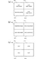
図2(b)の201は、光源部105のエリア251のみ点灯した状態で受光素子部101により撮影される画像を模式的に示している。画像201の4つのエリアI211、I212、I213、I214はそれぞれ受光素子部101のエリア211、212、213、234に対応している。また、各エリアI211〜I214の中に記載された符号は、各エリアI211〜I214の明るさ(受光素子部101で検出される光の強度)を示している。具体的には、S231は、観察対象物103のエリア231の透過光(図2(a)の実線矢印)に基づく明るさを表し、N231は、観察対象物103のエリア231を光が透過する際に発生した拡散光(図2(a)の点線矢印)に基づく明るさを表している。このように、光源部105のエリア251だけを点灯した場合であっても、観察対象物103のエリア231の拡散光が受光素子部101の他のエリア212、213、214にノイズN231として撮影されてしまう。
2B schematically illustrates an image photographed by the light receiving
図2(c)の202は、光源部105の全エリア251〜254を点灯した状態で受光素子部101により撮影される画像を模式的に示している。各エリアI211〜I214の中に記載された符号は、各エリアI211〜I214の明るさ(受光素子部101で検出される光の強度)を示している。S231、S232、S233、S234は、それぞれ観察対象物103のエリア231、232、233、234の透過光に基づく明るさを表している。また、N231、N232、N233、N234は、それぞれ観察対象物103のエリア231、232、233、234を光が透過する際に発生した拡散光に基づく明るさを表している。
2C schematically illustrates an image captured by the light receiving
受光素子部101のエリア211には、観察対象物101の対応エリア231の透過光と、対応エリア231の周辺のエリア232、233、234の拡散光とが到達し、それらの合成光が受光素子部101のエリア211にて画像化される。すなわち、画像202のエリアI211の明るさは、観察対象物103の対応エリア231の透過光に基づく明るさと、周辺エリア232、233、234の拡散光に基づく明るさの合計(S231+(N232+N233+N234))となる。拡散光に基づく明るさ(N232+N233+N234)はノイズ成分である。同様に、画像202のエリアI212の明るさは(S232+(N231+N233+N234))となる。また、エリアI213の明るさは、(S233+(N231+N232+N234))となり、エリアI214の明るさは、(S234+(N231+N232+N233))となる。このように、光源部105の全エリア251〜254を点灯させて受光素子部101の全エリア211〜214で撮影すると、対応エリア以外のエリアから到来するノイズ光に起因するノイズ成分を含む全体画像(ノイズ込画像)が取得されてしまう。
The transmitted light of the
次に図3(a)と図3(b)を用いて、光源の一部分を消灯してノイズ光のみを撮影する方法について説明する。
図3(a)の301は、光源部105のエリア251を消灯し、周辺の他のエリア252、253、254を点灯した状態で受光素子部101により撮影される画像を模式的に示している。このように、光源部105のエリア251のみを点灯させなかった場合、受光素子部101のエリア211には、観察対象物103の対応エリア以外のエリア232、233、234からのノイズ光のみが到達する。したがって、光源部105のエリア251を消灯して受光素子部101のエリア211で撮影することによって、観察対象物103のエリア232、233、234から受光素子部101のエリア211に入射するノイズ光のみを画像化することができる。このようにして得た画像301のエリアI211
の部分を、エリア211のノイズ画像と呼ぶ。ノイズ画像I211の明るさは、(N232+N233+N234)となる。
Next, a method for photographing only noise light by turning off a part of the light source will be described with reference to FIGS.
Is called a noise image of the
画像保存部106は、受光素子部101から電気信号化された画像データを受け取り保存する。画像保存部106は、全体制御部109からの指示により、受光素子部101全体で撮影した「ノイズ込画像」と受光素子部101の一部のエリアで撮影した「ノイズ画像」を保存する。
画像差分出力部107は、全体制御部109からの指示により、画像保存部106からノイズ込画像とノイズ画像を読み込み、ノイズ込画像からノイズ画像を減算した差分画像を作成し出力する。
The
The image
ノイズ込画像とノイズ画像との差分が、ノイズが除去された画像になることを説明する。
図3(b)の302は、ノイズ込画像である図2(c)の画像202と、エリア211のノイズ画像である図3(a)の画像301のエリアI211の部分との差分画像を示している。出力された差分画像302のエリアI211では、ノイズ成分(N232+N233+N234)が除去され、観察対象物103の対応エリア231の透過光のみに基づく画像が得られていることがわかる。なお、他のエリア212、213、214のノイズ成分を除去したい場合には、同様の処理を行えばよい。
It will be described that the difference between the noise-containing image and the noise image becomes an image from which noise has been removed.
302 in FIG. 3B shows a difference image between the
出力インターフェース108は、画像差分出力部107から出力される画像データを出力するインターフェースである。出力インターフェース108は、例えばTCP/IP(Transmission Control Protocol/Internet Protocol)等のプロトコルに従い補助記憶装置にデータを送信する。
The
全体制御部109は、受光素子部101と、光源部105と、画像保存部106と、画像差分出力部107に指示を出し、全体のノイズ込画像とノイズ画像を撮影させ、部分的にノイズが除去された画像を出力させる。
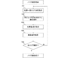
全体制御部109の制御について、図4(a)〜図4(c)のフローチャートを用いて説明する。図4(a)は、全体制御部109の制御全体の流れを示すフローチャートであり、ユーザにより設定された撮影指示により処理が開始され、ノイズが除去された画像を出力することで終了する。図4(b)は、全体撮影(図4(a)のステップ420)の詳細を示すフローチャートであり、図4(c)は、ノイズ撮影(図4(a)のステップ430)の詳細を示すフローチャートである。
The
The control of the
ステップ410において、ユーザからの撮影開始指示を受け取ると、全体制御部109がデジタルスキャナ100の各ユニットを制御し撮影準備を行う。例えば、観察対象物103であるスライドの搬送・設置、受光素子部101及び光源部105の起動、画像保存部105及び画像差分出力部107の初期化、ノイズを除去するエリアの設定などが実行される。
In
ステップ420の全体撮影処理(第1の撮影処理)は、光源部105により視野の全体を照明した状態で観察対象物103を撮影することにより、ノイズ込画像を取得する処理である。ステップ420の処理を図4(b)を用いて説明する。ステップ421では、全体制御部109が、光源部105に対し、全エリアの点灯を指示する。これにより、受光素子部101の全エリアに、観察対象物103の透過光が入光する。ステップ422では、全体制御部109が、受光素子部101に対し、全エリアの撮影を指示する。ステップ423では、全体制御部109が、光源部105に対し、全エリアの消灯を指示する。ステップ424では、全体制御部109が、画像保存部106に対し、受光素子101で撮影された全エリアの画像を「ノイズ込画像」として保存することを指示する。その結果、
図2(c)のノイズ込画像202を取得することができる。実際の装置では、受光素子部101から得られる画像データ(生データ)に対し、デモザイキング、ホワイトバランス調整、ガンマ補正、色補正、エンコードなどの必要な画像処理が行われるが、ここでは説明を割愛する。
The entire image capturing process (first image capturing process) in
The
ステップ430のノイズ撮影処理(第2の撮影処理)は、視野の一部エリアを照明しない(周辺エリアは照明する)状態で観察対象物103を撮影することにより、周辺エリアを照明した光に起因して一部エリア内に生じるノイズを画像化する処理である。ステップ430の処理を図4(c)を用いて説明する。ステップ431では、全体制御部109が、光源部105に対し、ノイズを除去するエリアに対応する光源を消灯し、それ以外のエリアに対応する光源(ノイズ光の原因となる光源)を点灯させる指示を行う。ステップ432では、全体制御部109が、受光素子部101に対し、ノイズを除去するエリア(消灯したエリアと対になるエリア)の撮影を指示する。消灯したエリアと対になるエリアには、観察対象物103の透過光が入射しないので、点灯したエリアに由来するノイズ光のみが撮影される。ステップ433では、全体制御部109が、光源部105に対し、全エリアの消灯を指示する。ステップ434では、全体制御部109が、画像保存部106に対し、受光素子101で撮影されたエリアの画像を「ノイズ画像」として保存することを指示する。その結果、図3(a)のノイズ画像I211を取得することができる。
The noise imaging process (second imaging process) in
ステップ440では、全体制御部109が、画像差分出力部107に対し、ノイズ込画像とノイズ画像との差分を出力するよう指示する。画像差分出力部107は、ノイズ込画像の各画素の画素値からノイズ画像の対応画素の画素値を減算することで、差分画像を生成する。なお、ノイズ込画像の画素値よりもノイズ画像の画素値の方が大きい場合には、差分画像の画素値はゼロにすればよい。その結果、図3(b)のノイズが除去された画像302を取得することができる。
In
ところで、特許文献1(特開2006−292421号公報)に提案された方法のように、撮影するエリアに対応する光源のみ点灯し、他を消灯すれば、撮影するエリアに入り込むノイズ光を低減することができる。これを応用すれば、ノイズ込画像の一部エリアのノイズを除去する方法として、一部エリアに対応する光源のみ点灯した状態で当該エリアのノイズなし画像を撮影し、ノイズ込画像の一部エリアをノイズなし画像に差し替える、という方法も考えられる。しかしながら、そのような方法の場合には、ドリフト現象に起因する画像境界の不連続の問題が顕在化する。つまり、ノイズ込画像の撮影とノイズなし画像の撮影のあいだに時間差があるため、その間に生じる温度変化によりフォーカス面等の変化が発生し、ノイズ込画像とノイズなし画像とのあいだに僅かなズレが生じる。そのため、ノイズ込画像の一部をノイズなし画像に差し替えると、その繋ぎ目において画像の不連続が発生してしまうのである。 By the way, as in the method proposed in Patent Document 1 (Japanese Patent Laid-Open No. 2006-292421), if only the light source corresponding to the area to be photographed is turned on and the others are turned off, the noise light entering the area to be photographed is reduced. be able to. If this is applied, as a method of removing the noise in a part of the noisy image, a noise-free image of the area is shot with only the light source corresponding to the part area turned on. It is also possible to replace the image with a noise-free image. However, in the case of such a method, the problem of discontinuity of the image boundary due to the drift phenomenon becomes obvious. In other words, since there is a time difference between shooting a noisy image and shooting a no-noise image, a change in the focus surface or the like occurs due to a temperature change that occurs during that time, and there is a slight deviation between the noisy image and the no-noise image. Occurs. For this reason, if a part of a noisy image is replaced with a noise-free image, discontinuity of the image occurs at the joint.
これに対し、本実施形態の方法では、観察対象物の全体画像(ノイズ込画像)を一度の撮影で取得するので(つまり画像の繋ぎ合わせを行わないので)、観察対象物の像の不連続という問題は発生しない。しかも、ノイズ画像はノイズ込画像に比べてダイナミックレンジが十分小さいので、ドリフト現象によりノイズ画像とノイズ込画像に含まれるノイズ成分とのあいだに多少のズレが生じたとしても、最終結果である差分画像の上では殆ど無視できる。したがって、本実施形態の方法によれば、画像全体で連続性が高く、且つ、ノイズ光に起因するノイズ成分が軽減された、高品質な画像を簡易な方法で得ることができる。 On the other hand, in the method of the present embodiment, since the entire image of the observation object (an image including noise) is acquired by one shooting (that is, the images are not joined together), the image of the observation object is discontinuous. The problem does not occur. In addition, the noise image has a sufficiently small dynamic range compared to the noise-included image, so even if there is some deviation between the noise image and the noise component included in the noise-included image due to the drift phenomenon, the difference that is the final result It is almost negligible on the image. Therefore, according to the method of the present embodiment, it is possible to obtain a high-quality image with high continuity over the entire image and with reduced noise components due to noise light by a simple method.
本実施形態では、明視野光学顕微鏡を持つデジタルスキャナを用いて説明したが、イメージセンサで撮影される領域の一部分を輝度制御できる方式であれば、光学系は明視野に限定されるものでなく、暗視野や蛍光などの顕微鏡でもよい。また、イメージセンサで撮
影できる光が得られれば、光学系は透過光に限定されるものではなく、反射光であってもよい。
In the present embodiment, a digital scanner having a bright field optical microscope has been described. However, the optical system is not limited to a bright field as long as it can control the brightness of a part of an area captured by an image sensor. A microscope such as dark field or fluorescence may be used. Further, the optical system is not limited to transmitted light as long as light that can be captured by an image sensor is obtained, and reflected light may be used.
ノイズ画像を作成するエリア(ノイズを除去するエリア)は、ユーザによって指定させてもよいし、固定のエリア(予め決まったエリア)でもよいし、全体制御部109がノイズを除去するエリアを自動で選択してもよい。例えば、事前の検査により観察対象物の中の関心部位(病変部位など)が分かっていれば、その関心部位に該当するエリアのノイズを除去すればよい。関心部位の検出は、ユーザが行ってもよいし、観察対象物103をプリスキャンしたデータもしくは全体撮影で得たノイズ込画像から画像処理により自動検出してもよい。デジタルスキャナ100が、画像診断を支援するための診断支援装置(不図示)と接続されており、診断支援装置から関心部位に関する情報の入力を受けてもよい。
An area for generating a noise image (an area for removing noise) may be designated by the user, or may be a fixed area (an area determined in advance), or the area for which the
本実施形態では、説明の便宜から、2×2の4つのエリアに分割する例を示したが、エリアの分割数や形状などは適宜設計できる。また本実施形態では、ノイズ画像の生成のため、ノイズを除去したいエリアと対になる光源部105のエリアのみ消灯し、他のエリアはすべて点灯した。しかし、ノイズを除去したいエリアへの影響が少ないと考えられるエリア、例えばノイズを除去したいエリアから遠いエリア、の光源は消灯してもよい。また本実施形態では、マイクロミラーアレイ素子を駆動することで光源部105の点灯/消灯エリアを制御したが、2次元のシャッターアレイにより光源部105の光を選択的に遮ることによっても同様の制御が実現できる。また本実施形態では、ノイズ画像を撮影する際に、一部の受光素子のみを用いて、ノイズを除去したいエリアの画像データのみを取得する構成としたが、受光素子部101の全体の画像データを取得した後にノイズ画像データを切り出してもよい。すなわち、観察対象物103の一部のエリアに対する照明は行わず、当該エリアの周辺のエリアは照明した状態で、当該エリアを撮影した画像(ノイズ画像)を取得できさえすれば、光源部105や受光素子部101の構成はどのようなものでもよい。
In the present embodiment, for the sake of convenience of explanation, an example in which the area is divided into 2 × 2 four areas is shown, but the number of areas and the shape of the areas can be designed as appropriate. In this embodiment, in order to generate a noise image, only the area of the
以上述べたように、本実施形態では、視野全体を照明した状態で観察対象物を撮影することでノイズ込画像(第1の画像)を取得すると共に、視野の一部エリアを消灯した状態で撮影することにより当該一部エリアのノイズ画像(第2の画像)を取得する。そして、ノイズ込画像の当該一部エリアに対応する部分から、ノイズ画像で表されるノイズ成分を減算することで、ノイズ除去処理を行う。したがって、広い視野の撮像装置であっても、照明光の拡散等に起因するノイズを除去しつつ、画像の境界における不連続を低減することができる。 As described above, in this embodiment, a noise-containing image (first image) is acquired by photographing the observation object with the entire field of view illuminated, and a part of the field of view is turned off. A noise image (second image) of the partial area is acquired by photographing. Then, noise removal processing is performed by subtracting the noise component represented by the noise image from the portion corresponding to the partial area of the noise-containing image. Therefore, even in an imaging device with a wide field of view, discontinuities at image boundaries can be reduced while removing noise caused by diffusion of illumination light or the like.
<第2実施形態>
前述した第1実施形態では、被写体の一部エリア(視野の一部)のノイズを軽減したが、第2実施形態では、被写体の全エリア(全視野)のノイズを軽減する。具体的には、第2実施形態では、一部エリアを消灯し当該エリアのノイズを撮影するという処理を、消灯するエリアを切り替えながら繰り返すことで、全エリアのノイズ画像を取得し、全エリアのノイズ込画像とノイズ画像とから差分画像を生成する。デジタルスキャナの基本構成は第1実施形態のものと同じであるが、全エリアのノイズ画像を取得するための制御が異なる。以下では、先に説明した第1実施形態と異なる構成を主に説明し、第1実施形態と共通する構成については説明を省略する。
Second Embodiment
In the first embodiment described above, noise in a part of the subject (part of the field of view) is reduced. In the second embodiment, noise in the whole area of the subject (full field of view) is reduced. Specifically, in the second embodiment, by repeating the process of turning off a part of the area and photographing the noise in the area while switching the area to be turned off, a noise image of the whole area is obtained. A difference image is generated from the noise-containing image and the noise image. The basic configuration of the digital scanner is the same as that of the first embodiment, but the control for acquiring noise images in all areas is different. In the following, the configuration different from the first embodiment described above will be mainly described, and the description of the configuration common to the first embodiment will be omitted.
図5(a)〜図5(c)を用いて、受光素子部101の全エリア(視野全体)のノイズ画像を撮影し差分画像を出力する方法について説明する。
With reference to FIGS. 5A to 5C, a method of capturing a noise image of all areas (entire field of view) of the light
図5(a)の601は、光源部105のエリア252を消灯し、周辺の他のエリア251、253、254を点灯した状態で受光素子部101により撮影される画像を模式的に
示している。エリア252を消灯し、観察対象物103の対応エリア232を照明しないことで、他のエリア231、233、234からのノイズ光に由来するノイズ画像I212を受光素子部101のエリア212で撮影できる。なお、ノイズのみを画像化できる理由は、第1実施形態の図3(a)の画像301について説明したのと同じ理由である。同様に、光源部105のエリア253を消灯し他のエリアを点灯した状態で、受光素子101のエリア213で撮影を行うことで、エリア213に対応するノイズ画像が得られる。また、光源部105のエリア254を消灯し他のエリアを点灯した状態で、受光素子101のエリア214で撮影を行うことで、エリア214に対応するノイズ画像が得られる。このように視野内を部分的に消灯しノイズ画像を撮影する処理を繰り返すことで、視野全体のノイズ画像を取得することができる。図5(b)の602は、4つのエリアのノイズ画像I211、I212、I213、I214を合成して得た、視野全体のノイズ画像を示している。
図5(c)の603は、ノイズ込画像(図2(c)の画像202)と、全体ノイズ画像(図5(b)の画像602)との差分画像を示している。このように、第1実施形態で作成したノイズ込画像とエリアごとに作成したノイズ画像とを用いることで、視野全体のノイズを除去できることがわかる。
第2実施形態の全体制御部109の制御について、図4(a)、図4(b)、図6のフローチャートを用いて説明する。第1実施形態との違いは、図4(a)のステップ430のノイズ撮影の処理が図6に示すものに置き換わっている点のみであり、その他の処理は第1実施形態と同じである。
The control of the
本実施形態のノイズ撮影ステップ430では、受光素子部101の一部分のエリアでノイズ画像を取得する処理を繰り返し、ステップ420で撮影した全エリア分のノイズ画像を取得する。本実施形態のノイズ撮影ステップ430の処理を図6を用いて説明する。
In the
ステップ731では、全体制御部109が、光源部105に対し、一部エリアの光源を消灯し、その周辺エリアの光源(ノイズ光の原因となる光源)を点灯させる指示を行う。全体制御部109は、ステップ731〜ステップ735のループを繰り返す度に、光源を消灯するエリア(ノイズ画像を撮影するエリア)を切り換える。例えば、全体制御部109は、初回は光源部105のエリア251を消灯し、2回目はエリア252、3回目はエリア253、4回目はエリア254を順に消灯する。
In
ステップ432、ステップ433、ステップ434は、図4(c)と同じ処理であり、消灯されたエリアのノイズ画像を撮影し保存するステップである。ステップ735では、全体制御部509が、全エリアのノイズ画像を撮影したかどうか判定を行い、不足があった場合にステップ731に戻り、次のエリアの撮影を行うよう指示する。具体的には光源部105の各エリア251、252、253、254を順に消灯し、対となる受光素子部101のエリア211、212、213、214を順に撮影することで、図5(b)に示す全エリアのノイズ画像602を作成することができる。全エリアのノイズ画像が撮影された場合、ノイズ撮影処理を終了し、図4(a)のステップ440に進む。
ステップ440では、全体制御部109が、画像差分出力部107に対し、ノイズ込画像(図2の202)とノイズ画像(図5の602)の差分を出力するよう指示する。その結果、全エリアのノイズが除去された画像(図5の603)を取得することができる。
In
前述したように、ノイズ込画像と各ノイズ画像とのあいだには、撮影の時間差に起因するズレが発生する。しかしながら、本実施形態の方法では、観察対象物の全体画像(ノイズ込画像)を一度の撮影で取得するので、観察対象物の像の不連続という問題は発生しな
い。しかも、ノイズ画像はノイズ込画像に比べてダイナミックレンジが十分小さいので、ドリフト現象によりノイズ画像とノイズ込画像に含まれるノイズ成分とのあいだに多少のズレが生じたとしても、最終結果である差分画像の上では殆ど無視できる。したがって、本実施形態の方法によれば、画像全体で連続性が高く、且つ、ノイズ光に起因するノイズ成分が軽減された、高品質な画像を簡易な方法で得ることができる。
As described above, there is a difference between the noise-included image and each noise image due to the time difference of shooting. However, in the method according to the present embodiment, the entire image of the observation target (an image including noise) is acquired by one shooting, and therefore the problem of discontinuity of the image of the observation target does not occur. In addition, the noise image has a sufficiently small dynamic range compared to the noise-included image, so even if there is some deviation between the noise image and the noise component included in the noise-included image due to the drift phenomenon, the difference that is the final result It is almost negligible on the image. Therefore, according to the method of the present embodiment, it is possible to obtain a high-quality image with high continuity over the entire image and with reduced noise components due to noise light by a simple method.
本実施形態では、光源部105を消灯するエリア(照明しないエリア)が互いに重ならないようにノイズ撮影処理を複数回実行することで、複数のエリアそれぞれのノイズ画像を取得し、それらを繋ぎあわせることで視野全体のノイズ画像を作成した。しかし、視野全体のノイズ画像を取得することができれば、前述の方法に限らない。例えば、ノイズを発生させてしまう光源を順に点灯し、受光素子101の対応する消灯エリアの撮影を行うことでノイズ画像を取得する方法でも構わない。つまり、消灯エリア(照明しないエリア)が部分的に重なりをもち、且つ、点灯エリア(照明するエリア)が互いに重ならないように、ノイズ撮影処理を複数回実行し、それらを足し合わせる(重ね合せる)ことで視野全体のノイズ画像を作成するのである。図7(a)〜図7(d)を用いて詳しく説明する。
In the present embodiment, the noise image capturing process is performed a plurality of times so that areas where the
図7(a)の801は、光源部105のエリア252、253、254を消灯し、エリア251だけを点灯した状態で、受光素子部101により撮影される画像を模式的に示している。受光素子部101のエリア212、213、214において、観察対象物103のエリア231からのノイズ光に起因するノイズ成分N231を画像化できることがわかる。図7(b)の802は、光源部105のエリア252のみを点灯した状態で、観察対象物103のエリア232からのノイズ光を撮影した画像である。図7(c)の803は、光源部105のエリア253のみを点灯した状態で、観察対象物103のエリア233からのノイズ光を撮影した画像である。図7(d)の804は光源部105のエリア254のみを点灯した状態で、観察対象物103のエリア234からのノイズ光を撮影した画像である。画像801のエリアI212〜I214と、画像802のエリアI211、I213、I214と、画像803のエリアI211、I212、I214と、画像804のエリアI211〜I213とを合算すると、図5(b)と同様の全体ノイズ画像が得られる。
図7(a)〜図7(d)に示す方法は、各エリアにおいてノイズ画像の足し合わせを行うので、ノイズ画像間の撮影時間差による像ズレを分散させる効果がある。したがって、図5(a)に示すようなエリア毎にノイズ画像を撮影する方法に比べ、差分画像全体の連続性を更に向上することができる。 The method shown in FIGS. 7A to 7D adds noise images in each area, and thus has an effect of dispersing image displacement due to a photographing time difference between noise images. Therefore, the continuity of the entire difference image can be further improved as compared with the method of capturing a noise image for each area as shown in FIG.
本実施形態では、ノイズ画像を作成するエリアを受光素子部101の全体エリアとしたが、必ずしも全体のエリアである必要はなく、ノイズを軽減したい複数エリアのみでもよい。また、デジタルスキャナが1つの視野内に複数の受光素子部101を備える構成であれば、複数の受光素子部101のそれぞれに対し、上記処理を適用してもよい。また、一度に撮影可能な視野に比べて観察対象物が大きいために、観察対象物を相対移動させて複数回の撮影を行う場合には、撮影の度に上記処理を適用してもよい。
In the present embodiment, the area where the noise image is created is the entire area of the light
以上述べたように、本実施形態では、ノイズ撮影処理を複数回実行することで、視野内の複数エリア又は全エリアに対応するノイズ画像を取得する。そして、視野全体を照明した状態で撮影したノイズ込画像から、複数エリア又は全エリアのノイズ成分を除去する。したがって、第1実施形態と同様、広い視野の撮像装置であっても、照明光の拡散等に起因するノイズを除去しつつ、画像の境界における不連続を低減することができる。さらに、本実施形態の方法によれば、第1実施形態よりも広い範囲のノイズ除去が可能である。 As described above, in this embodiment, noise images corresponding to a plurality of areas or all areas in the field of view are acquired by executing the noise imaging process a plurality of times. Then, noise components in a plurality of areas or all areas are removed from the noise-containing image captured in a state where the entire field of view is illuminated. Therefore, as in the first embodiment, even an imaging device with a wide field of view can reduce discontinuities at the image boundaries while removing noise caused by diffusion of illumination light or the like. Furthermore, according to the method of the present embodiment, it is possible to remove noise in a wider range than in the first embodiment.
100 デジタルスキャナ
101 受光素子部
103 観察対象物
105 光源部
107 画像差分出力部
109 全体制御部
DESCRIPTION OF
Claims (14)
前記光源部により照明された前記被写体を撮影する受光素子部と、
前記光源部により前記被写体の全体を照明した状態で前記被写体を撮影することにより、第1の画像を取得する第1の撮影処理と、前記光源部により前記被写体の第1エリアを照明せず、且つ、前記第1エリアの周辺の第2エリアを照明した状態で前記被写体を撮影することにより、前記第2エリアを照明した光に起因して前記第1エリア内に生じるノイズを表す第2の画像を取得する第2の撮影処理と、を実行する制御部と、
前記第2の画像を用いて、前記第1の画像の前記第1エリアに対応する部分からノイズを除去するノイズ除去処理を実行する画像処理部と、
を備える
ことを特徴とする撮像装置。 A light source for illuminating the subject;
A light receiving element portion for photographing the subject illuminated by the light source portion;
A first photographing process for obtaining a first image by photographing the subject in a state where the whole of the subject is illuminated by the light source unit, and a first area of the subject is not illuminated by the light source unit, And a second image representing noise generated in the first area due to light illuminating the second area by photographing the subject in a state where the second area around the first area is illuminated. A second imaging process for acquiring an image ;
An image processing unit that performs noise removal processing for removing noise from a portion corresponding to the first area of the first image using the second image ;
Imaging device according to claim Bei obtain <br/> things.
ことを特徴とする請求項1に記載の撮像装置。 The imaging apparatus according to claim 1, wherein the noise removal process is a process of subtracting the second image from a portion corresponding to the first area of the first image.
ことを特徴とする請求項1又は2に記載の撮像装置。 The imaging device according to claim 1, wherein the light source unit is an illumination device that illuminates the subject with parallel light.
前記光源部と前記固定部と前記光学系によって顕微鏡装置が構成されている
ことを特徴とする請求項1〜3のうちいずれか1項に記載の撮像装置。 A fixed portion that supports the subject, and an optical system that expands an optical image of the subject and guides it to the light receiving element portion,
The imaging apparatus according to claim 1, wherein a microscope apparatus is configured by the light source unit, the fixed unit, and the optical system.
前記画像処理部は、前記複数の第2の画像を用いて、前記第1の画像の前記複数の第1エリアに対応する部分からノイズを除去する
ことを特徴とする請求項1〜4のうちいずれか1項に記載の撮像装置。 The controller obtains a plurality of second images for a plurality of first areas by executing the second imaging process a plurality of times while changing the first area that is not illuminated,
The image processing unit removes noise from a portion corresponding to the plurality of first areas of the first image using the plurality of second images. The imaging device according to any one of the above.
ことを特徴とする請求項5に記載の撮像装置。 The imaging apparatus according to claim 5, wherein the control unit acquires the plurality of second images so that the first areas that are not illuminated do not overlap each other.
ことを特徴とする請求項5に記載の撮像装置。 Claim wherein the control unit, the first area that does not lighting has partially overlap, and, wherein said second area which illuminates to acquire the plurality of second image so as not to overlap each other 5. The imaging device according to 5.
前記光源部により照明された前記被写体を撮影する受光素子部と、
画像処理部と、
を備える撮像装置の制御方法であって、
前記光源部により前記被写体の全体を照明した状態で前記被写体を撮影することにより、第1の画像を取得するステップと、
前記光源部により前記被写体の第1エリアを照明せず、且つ、前記第1エリアの周辺の第2エリアを照明した状態で前記被写体を撮影することにより、前記第2エリアを照明した光に起因して前記第1エリア内に生じるノイズを表す第2の画像を取得するステップと、
前記画像処理部によって、前記第2の画像を用いて、前記第1の画像の前記第1エリアに対応する部分からノイズを除去するステップと、
を含むことを特徴とする撮像装置の制御方法。 A light source for illuminating the subject;
A light receiving element portion for photographing the subject illuminated by the light source portion;
An image processing unit;
An imaging apparatus control method comprising:
Obtaining a first image by photographing the subject in a state where the whole of the subject is illuminated by the light source unit;
Not illuminate the first area of the subject by the light source unit, and, by photographing the subject while illuminating the second area of the periphery of the first area, due to the light illuminating the second area And obtaining a second image representing noise occurring in the first area;
Removing noise from a portion corresponding to the first area of the first image using the second image by the image processing unit;
A method for controlling an imaging apparatus, comprising:
ことを特徴とする請求項8に記載の撮像装置の制御方法。 The imaging apparatus according to claim 8, wherein the image processing unit removes noise by subtracting the second image from a portion corresponding to the first area of the first image. Control method.
ことを特徴とする請求項8又は9に記載の撮像装置の制御方法。 The method of controlling an imaging apparatus according to claim 8, wherein the light source unit is an illumination device that illuminates the subject with parallel light.
前記光源部と前記固定部と前記光学系によって顕微鏡装置が構成されている
ことを特徴とする請求項8〜10のうちいずれか1項に記載の撮像装置の制御方法。 The imaging apparatus includes a fixing unit that supports the subject, and an optical system that expands an optical image of the subject and guides it to the light receiving element unit,
The method for controlling an imaging apparatus according to claim 8, wherein a microscope apparatus is configured by the light source unit, the fixed unit, and the optical system.
前記画像処理部は、前記複数の第2の画像を用いて、前記第1の画像の前記複数の第1エリアに対応する部分からノイズを除去する
ことを特徴とする請求項8〜11のうちいずれか1項に記載の撮像装置の制御方法。 Acquiring a plurality of second images for a plurality of first areas by executing the step of acquiring the second image a plurality of times while changing the first area not illuminated;
The image processing unit removes noise from a portion corresponding to the plurality of first areas of the first image using the plurality of second images. The control method of an imaging device given in any 1 paragraph.
ことを特徴とする請求項12に記載の撮像装置の制御方法。 The imaging according to claim 12, wherein the plurality of second images are acquired so that the first areas that are not illuminated partially overlap each other and the second areas that are illuminated do not overlap each other. Control method of the device.
Priority Applications (1)
| Application Number | Priority Date | Filing Date | Title |
|---|---|---|---|
| JP2013150186A JP6124718B2 (en) | 2013-07-19 | 2013-07-19 | Imaging apparatus and control method thereof |
Applications Claiming Priority (1)
| Application Number | Priority Date | Filing Date | Title |
|---|---|---|---|
| JP2013150186A JP6124718B2 (en) | 2013-07-19 | 2013-07-19 | Imaging apparatus and control method thereof |
Publications (3)
| Publication Number | Publication Date |
|---|---|
| JP2015023433A JP2015023433A (en) | 2015-02-02 |
| JP2015023433A5 JP2015023433A5 (en) | 2016-09-08 |
| JP6124718B2 true JP6124718B2 (en) | 2017-05-10 |
Family
ID=52487540
Family Applications (1)
| Application Number | Title | Priority Date | Filing Date |
|---|---|---|---|
| JP2013150186A Active JP6124718B2 (en) | 2013-07-19 | 2013-07-19 | Imaging apparatus and control method thereof |
Country Status (1)
| Country | Link |
|---|---|
| JP (1) | JP6124718B2 (en) |
Family Cites Families (3)
| Publication number | Priority date | Publication date | Assignee | Title |
|---|---|---|---|---|
| JP2006292421A (en) * | 2005-04-06 | 2006-10-26 | Sharp Corp | Fluorescence detector |
| JP5006062B2 (en) * | 2007-02-05 | 2012-08-22 | オリンパス株式会社 | Virtual slide creation device, virtual slide creation method, and virtual slide creation program |
| EP2604176A4 (en) * | 2010-09-30 | 2015-11-04 | Olympus Corp | Imaging device |
-
2013
- 2013-07-19 JP JP2013150186A patent/JP6124718B2/en active Active
Also Published As
| Publication number | Publication date |
|---|---|
| JP2015023433A (en) | 2015-02-02 |
Similar Documents
| Publication | Publication Date | Title |
|---|---|---|
| JP5856733B2 (en) | Imaging device | |
| JP6104493B1 (en) | Imaging system | |
| JP2004101871A (en) | Photographing apparatus for microscope image | |
| JP5677864B2 (en) | Microscope imaging apparatus and microscope observation method | |
| JP6624939B2 (en) | Image processing device, imaging device, and image processing program | |
| JP2014230708A (en) | Endoscope | |
| JP2008043742A (en) | Electronic endoscope system | |
| JPWO2018163500A1 (en) | Endoscope device | |
| JP7012549B2 (en) | Endoscope device, control method of endoscope device, control program of endoscope device, and recording medium | |
| JP5272699B2 (en) | Image processing apparatus, imaging apparatus, program, and image processing method | |
| JP2007215907A (en) | Endoscope processor, endoscopic system and black balance adjustment program | |
| JP2014228851A (en) | Endoscope device, image acquisition method, and image acquisition program | |
| JP6430880B2 (en) | Endoscope system and method for operating endoscope system | |
| JP2019080623A (en) | Endoscope apparatus | |
| JP6124718B2 (en) | Imaging apparatus and control method thereof | |
| JP2021104229A (en) | Ocular fundus image processing device and ocular fundus image processing program | |
| JP2008304541A (en) | Microscope imaging device | |
| JP6017749B1 (en) | IMAGING DEVICE AND IMAGING DEVICE OPERATING METHOD | |
| JP2013074929A (en) | Oral cavity interior observation device and oral cavity interior observation system | |
| JP6277138B2 (en) | Endoscope system and operating method thereof | |
| JP3981376B2 (en) | Magnification imaging adapter | |
| JP2012239766A (en) | Light source device for endoscope | |
| JP2007036951A (en) | Camera having electronic viewfinder | |
| JP2012183193A (en) | Electronic endoscope apparatus | |
| WO2012117673A1 (en) | Digital microscope |
Legal Events
| Date | Code | Title | Description |
|---|---|---|---|
| A521 | Request for written amendment filed |
Free format text: JAPANESE INTERMEDIATE CODE: A523 Effective date: 20160715 |
|
| A621 | Written request for application examination |
Free format text: JAPANESE INTERMEDIATE CODE: A621 Effective date: 20160715 |
|
| A977 | Report on retrieval |
Free format text: JAPANESE INTERMEDIATE CODE: A971007 Effective date: 20170223 |
|
| TRDD | Decision of grant or rejection written | ||
| A01 | Written decision to grant a patent or to grant a registration (utility model) |
Free format text: JAPANESE INTERMEDIATE CODE: A01 Effective date: 20170307 |
|
| A61 | First payment of annual fees (during grant procedure) |
Free format text: JAPANESE INTERMEDIATE CODE: A61 Effective date: 20170404 |
|
| R151 | Written notification of patent or utility model registration |
Ref document number: 6124718 Country of ref document: JP Free format text: JAPANESE INTERMEDIATE CODE: R151 |