JP6124483B2 - Game machine - Google Patents

Game machine Download PDF

Info

Publication number
JP6124483B2
JP6124483B2 JP2016051157A JP2016051157A JP6124483B2 JP 6124483 B2 JP6124483 B2 JP 6124483B2 JP 2016051157 A JP2016051157 A JP 2016051157A JP 2016051157 A JP2016051157 A JP 2016051157A JP 6124483 B2 JP6124483 B2 JP 6124483B2
Authority
JP
Japan
Prior art keywords
guide plate
light guide
light
display
frame
Prior art date
Legal status (The legal status is an assumption and is not a legal conclusion. Google has not performed a legal analysis and makes no representation as to the accuracy of the status listed.)
Expired - Fee Related
Application number
JP2016051157A
Other languages
Japanese (ja)
Other versions
JP2016105901A (en
JP2016105901A5 (en
Inventor
小倉 敏男
敏男 小倉
Current Assignee (The listed assignees may be inaccurate. Google has not performed a legal analysis and makes no representation or warranty as to the accuracy of the list.)
Sankyo Co Ltd
Original Assignee
Sankyo Co Ltd
Priority date (The priority date is an assumption and is not a legal conclusion. Google has not performed a legal analysis and makes no representation as to the accuracy of the date listed.)
Filing date
Publication date
Application filed by Sankyo Co Ltd filed Critical Sankyo Co Ltd
Priority to JP2016051157A priority Critical patent/JP6124483B2/en
Publication of JP2016105901A publication Critical patent/JP2016105901A/en
Publication of JP2016105901A5 publication Critical patent/JP2016105901A5/ja
Application granted granted Critical
Publication of JP6124483B2 publication Critical patent/JP6124483B2/en
Expired - Fee Related legal-status Critical Current
Anticipated expiration legal-status Critical

Links

Images

Description

本発明は、遊技機に係り、詳しくは、遊技用価値を用いて遊技を行うことが可能なパチンコ遊技機やスロットマシン等の遊技機に関する。   The present invention relates to a gaming machine, and more particularly, to a gaming machine such as a pachinko gaming machine or a slot machine capable of playing a game using gaming value.

遊技機の一例として、遊技球などの遊技媒体を発射装置によって遊技領域に発射し、遊技領域に設けられている入賞口などの入賞領域に遊技媒体が入賞したことに基づいて、所定の遊技価値を付与可能としたパチンコ遊技機がある。また、遊技機の他の一例として、メダルやコイン、あるいは、パチンコ遊技機と同様の遊技球といった遊技媒体を用いて1ゲームに対する所定数の賭数を設定した後、遊技者がスタートレバーを操作することにより可変表示装置による表示図柄の可変表示を開始し、導出された表示結果に基づいて所定の遊技価値を付与可能としたスロットマシンがある。   As an example of a gaming machine, a gaming medium such as a game ball is launched into a gaming area by a launching device, and a predetermined gaming value is determined based on the winning of a gaming medium in a winning area such as a winning opening provided in the gaming area. There is a pachinko machine that can be granted. As another example of the gaming machine, after setting a predetermined number of bets for one game using a game medium such as a medal, a coin, or a game ball similar to a pachinko gaming machine, the player operates the start lever. Thus, there is a slot machine that starts variable display of display symbols by the variable display device, and can give a predetermined game value based on the derived display result.

この種の遊技機では、遊技に関連する演出を行う演出手段の一例として、例えば、導光板を用いた表示装置を備えるものがある(例えば、特許文献1参照)。この表示装置では、発光ダイオードなどの光源から導光板の端面を透して内部に光を入射させ、導光板に設けた反射部により入射光を反射させることで、導光板に表示情報を表示することができる(例えば、特許文献1参照)。   In this type of gaming machine, as an example of an effect unit that performs an effect related to a game, for example, there is one provided with a display device using a light guide plate (see, for example, Patent Document 1). In this display device, light is incident from the light source such as a light-emitting diode through the end face of the light guide plate, and the incident light is reflected by a reflection portion provided on the light guide plate, thereby displaying display information on the light guide plate. (For example, refer to Patent Document 1).

特開2009−207880号公報JP 2009-207880 A

特許文献1に記載の表示装置では、表示可能な表示情報を増やすために、それぞれに異なるパターンに反射部が設けられた2枚の導光板を重ねて配置している。しかし、導光板は、光が入射されないときには反射部が目立たないように形成されているので、2枚の導光板を重ねて表示装置を組み立てるときには、2枚の導光板の前後を間違えて組み付けてしまったり、同一の導光板を2枚重ねて組み付けてしまう虞がある。   In the display device described in Patent Document 1, in order to increase display information that can be displayed, two light guide plates each provided with a reflective portion in a different pattern are overlapped. However, the light guide plate is formed so that the reflecting portion is not conspicuous when light is not incident. Therefore, when assembling the display device with the two light guide plates stacked, the front and rear of the two light guide plates are mistakenly assembled. There is a possibility that two identical light guide plates may be stacked and assembled.

この発明は、上記実状に鑑みてなされたものであり、複数の導光板を容易に組み付けることができる遊技機を提供することを目的とする。   This invention is made | formed in view of the said actual condition, and it aims at providing the game machine which can assemble | attach a some light-guide plate easily.

(1) 上記目的を達成するため、本発明の第1の観点に係る遊技機は、遊技用価値を用いて遊技を行うことが可能な遊技機(例えば、パチンコ遊技機1)であって、透光性を有し、遊技者が視認可能に配置された第1導光板(例えば、前導光板42A)と、透光性を有し、遊技者が視認可能に配置された第2導光板(例えば、後導光板42B)と、前記第1導光板と前記第2導光板とを対面させて保持する保持部材(例えば、フレーム体50)と、を備え、前記第1導光板は、該第1導光板の側面から内部に入射される光源からの光により発光して該第1導光板に画像を表示させる第1発光部(例えば、前導光板42Aの前面と背面とに形成された発光部46Aa、46Ab)を有するとともに、光源からの光が入射される面から離れた位置に第1取付部が設けられ(例えば集光レンズ62と面しない位置に貫通孔43が形成されるなど)、前記第2導光板は、該第2導光板の側面から内部に入射される光源からの光により発光して該第2導光板に前記第1導光板とは異なる画像を表示させる第2発光部を有するとともに(例えば、後導光板42Bの前面と背面とに形成された発光部46Ba、46Bb)、光源からの光が入射される面から離れ、かつ前記第1導光板の第1取付部とは異なる位置に第2取付部が設けられ(例えば、集光レンズ62と面しない位置で、かつ前導光板42Aの貫通孔43とは異なる位置に貫通孔43が形成されるなど)、前記保持部材には、前記第1導光板の第1取付部に対応する位置に第1固定部が設けられているとともに前記第2導光板の第2取付部に対応する位置に第2固定部が設けられており、該保持部材は、前記第1固定部と前記第1取付部とが第1の係合部材で係合されることにより前記第1導光板を保持するとともに、前記第2固定部と前記第2取付部とが第2の係合部材で係合されることにより前記第2導光板を保持し(例えば、フレーム体50の前面に、前導光板42Aの貫通孔43に対応して凹部52e、54e、56eが形成され、フレーム体50の背面に、後導光板42Bの貫通孔43に対応して凹部52f、54f、56fが形成され、前面の凹部52e、54e、56eを通じて前導光板42Aをフレーム体50のネジ孔52d、54d、56dにネジ止めするとともに、背面の凹部52f、54f、56fを通じて後導光板42Bをフレーム体50のネジ孔52d、54d、56dにネジ止めするなど)、前記第1導光板及び前記第2導光板のうち、一方の導光板に画像を表示して行う演出と、両方の導光板に画像を表示して行う演出とを実行可能な(例えば、後導光板42Bのみに画像を表示する演出(図14(a)、(b))、前導光板42Aのみに画像を表示する演出(図15(a)、(b))、及び前導光板42A及び後導光板42Bに画像を表示する演出(図14(c))を実行する)演出実行手段(例えば、表示用LED67を制御するためのLED基板66)と、前記光源からの光が入射し、前記第1導光板あるいは前記第2導光板に向けて光を出射して発光させる集光部材(例えば、図12に記載の集光レンズ62)と、を更に備え、前記集光部材の光出射面は、前記第1導光板あるいは前記第2導光板に向けて凸状の湾曲面である(例えば図4に記載のように、集光レンズ62における前導光板42A及び後導光板42Bに対向する面(出射面)は、複数の湾曲面(レンズ面)を構成している)、ことを特徴とする。 (1) In order to achieve the above object, a gaming machine according to the first aspect of the present invention is a gaming machine (for example, pachinko gaming machine 1) capable of playing a game using a gaming value, A first light guide plate (for example, the front light guide plate 42A) that is translucent and disposed so that the player can visually recognize, and a second light guide plate that is translucent and disposed so that the player can visually recognize ( For example, the rear light guide plate 42B) and a holding member (for example, the frame body 50) that holds the first light guide plate and the second light guide plate facing each other, the first light guide plate includes the first light guide plate 1st light emission part which light-emits with the light from the light source incident inside from the side surface of 1 light-guide plate, and displays an image on this 1st light-guide plate (For example, the light emission part formed in the front surface and back surface of 42 A of front light-guide plates 46Aa, 46Ab) and a position away from the surface on which light from the light source is incident A first mounting portion (for example, a through hole 43 is formed at a position not facing the condenser lens 62), and the second light guide plate is a light source that is incident on the inside from the side surface of the second light guide plate. A second light emitting unit that emits light from the light and causes the second light guide plate to display an image different from the first light guide plate (for example, a light emitting unit formed on the front and back surfaces of the rear light guide plate 42B). 46Ba, 46Bb), a second mounting portion is provided at a position different from the first mounting portion of the first light guide plate away from the surface on which light from the light source is incident (for example, does not face the condensing lens 62) The through hole 43 is formed at a position different from the through hole 43 of the front light guide plate 42A), and the holding member is first fixed at a position corresponding to the first mounting portion of the first light guide plate. A second portion of the second light guide plate is provided. A second fixing portion is provided at a position corresponding to the portion, and the holding member is configured such that the first fixing portion and the first mounting portion are engaged with each other by the first engaging member. While holding the light guide plate, the second fixing portion and the second mounting portion are engaged by the second engaging member to hold the second light guide plate (for example, on the front surface of the frame body 50). The recesses 52e, 54e, 56e are formed corresponding to the through holes 43 of the front light guide plate 42A, and the recesses 52f, 54f, 56f are formed on the back surface of the frame body 50 corresponding to the through holes 43 of the rear light guide plate 42B. The front light guide plate 42A is screwed to the screw holes 52d, 54d, 56d of the frame body 50 through the front recesses 52e, 54e, 56e, and the rear light guide plate 42B is screwed into the screw of the frame body 50 through the rear recesses 52f, 54f, 56f. Hole 2d, 54d, 56d, etc.), of the first light guide plate and the second light guide plate, displaying the image on one light guide plate, and displaying the image on both light guide plates (For example, an effect of displaying an image only on the rear light guide plate 42B (FIGS. 14A and 14B), an effect of displaying an image only on the front light guide plate 42A (FIG. 15A), (b)), and effect of displaying an image before the light guide plate 42A and the rear light guide plate 42B and executes (FIG 14 (c))) demonstration execution unit (e.g., LED board 66 for controlling the display LED 67) A light condensing member (for example, the condensing lens 62 shown in FIG. 12) that emits light by emitting light toward the first light guide plate or the second light guide plate when light from the light source enters. further example Bei, the light emitting surface of the light focusing element, the first light guide plate Oh Alternatively, it is a curved surface convex toward the second light guide plate (for example, as shown in FIG. 4, the surface (outgoing surface) facing the front light guide plate 42 </ b> A and the rear light guide plate 42 </ b> B of the condenser lens 62 is A plurality of curved surfaces (lens surfaces)) .

このような構成によれば、第1導光板と第2導光板とのそれぞれに光源から光を入射させることによって、第1導光板と第2導光板に画像を表示させることができる。そして、第1導光板の取付部と第2導光板の取付部の位置が異なっているので、第1導光板と第2導光板と保持部材との組み付け間違いを防止することができ、複数の導光板と保持部材を容易に組み付けることができる。
尚、「第1発光部」と「第2発光部」は、光源からの光を反射させて光出射面から出射させる凹部等からなる反射部や、光出射面に形成されて光源からの光を全反射させずに光出射面から出射させる凸部等からなる透光部を含む。
According to such a configuration, an image can be displayed on the first light guide plate and the second light guide plate by causing light from the light source to enter each of the first light guide plate and the second light guide plate. And since the position of the attachment part of the 1st light guide plate and the attachment part of the 2nd light guide plate is different, the assembly mistake of the 1st light guide plate, the 2nd light guide plate, and a holding member can be prevented, and a plurality of The light guide plate and the holding member can be easily assembled.
The “first light emitting part” and the “second light emitting part” are a reflecting part including a concave part that reflects light from the light source and emits the light from the light emitting surface, and light from the light source formed on the light emitting surface. Including a light-transmitting portion made of a convex portion that emits light from the light-emitting surface without being totally reflected.

(2) 本発明の第2の観点に係る遊技機は、遊技用価値を用いて遊技を行うことが可能な遊技機(例えば、パチンコ遊技機1)であって、透光性を有し、遊技者が視認可能に配置された第1導光板(例えば、前導光板142A)と、透光性を有し、遊技者が視認可能に配置された第2導光板(例えば、後導光板142B)と、前記第1導光板と前記第2導光板とを対面させて保持する保持部材(例えば、フレーム枠体504)と、を備え、前記第1導光板は、該第1導光板の側面から内部に入射される光源からの光により発光して該第1導光板の板面に画像を表示させる第1発光部(例えば、前導光板142Aの背面に形成された発光部46)を有するとともに、光源からの光が入射される面から離れた位置に第1被当接部(例えば、前導光板142Aに、集光レンズ62と面しない位置に差込部143Aが形成されるなど)が設けられ、前記第2導光板は、該第2導光板の側面から内部に入射される光源からの光により発光して該第2導光板の板面に前記第1導光板とは異なる画像を表示させる第2発光部(例えば、後導光板42Bの背面とに形成された発光部46)を有するとともに、光源からの光が入射される面から離れ、かつ前記第1導光板の第1被当接部とは異なる形状の第2被当接部が設けられ(例えば、後導光板142Bに、集光レンズ62と面しない位置に、前導光板142Aの差込部143Aとは異なる形状の差込部143Bが形成されるなど)、前記保持部材には、前記第1導光板を保持するときに該第1導光板の第1被当接部に当接する第1当接部が設けられているとともに(例えば、フレーム枠体504に、前導光板142Aを保持するときに差込部143Aと当接する差込溝508aが形成されるなど)、前記第2導光板を保持するときに該第2導光板の第2被当接部に当接する第2当接部が設けられ(例えば、フレーム枠体504に、後導光板142Bを保持するときに差込部143Bと当接する差込溝508bが形成されるなど)、前記第1導光板及び前記第2導光板のうち、一方の導光板の板面に画像を表示して行う演出と、両方の導光板の板面に画像を表示して行う演出とを実行可能な(例えば、後導光板42Bのみに画像を表示する演出(図14(a)、(b))、前導光板42Aのみに画像を表示する演出(図15(a)、(b))、及び前導光板42A及び後導光板42Bに画像を表示する演出(図14(c))を実行する)演出実行手段(例えば、表示用LED67を制御するためのLED基板66)と、前記光源からの光が入射し、前記第1導光板あるいは前記第2導光板に向けて光を出射して発光させる集光部材(例えば、図12に記載の集光レンズ62)と、を更に備え、前記集光部材の光出射面は、前記第1導光板あるいは前記第2導光板に向けて凸状の湾曲面である(例えば図4に記載のように、集光レンズ62における前導光板42A及び後導光板42Bに対向する面(出射面)は、複数の湾曲面(レンズ面)を構成している)、ことを特徴とする。 (2) A gaming machine according to the second aspect of the present invention is a gaming machine (for example, a pachinko gaming machine 1) capable of playing a game using a gaming value, and has translucency. A first light guide plate (for example, the front light guide plate 142A) disposed so as to be visible to the player, and a second light guide plate (for example, the rear light guide plate 142B) that is translucent and disposed so as to be visible to the player. And a holding member (for example, a frame frame 504) that holds the first light guide plate and the second light guide plate facing each other, and the first light guide plate is formed from a side surface of the first light guide plate. While having a first light emitting unit (for example, a light emitting unit 46 formed on the back surface of the front light guide plate 142A) that emits light from a light source incident on the inside and displays an image on the plate surface of the first light guide plate, The first contacted part (for example, the front light guide) is located away from the surface on which light from the light source is incident. The plate 142A is provided with an insertion portion 143A formed at a position that does not face the condenser lens 62), and the second light guide plate is supplied from a light source incident inside from the side surface of the second light guide plate. A second light emitting unit (for example, a light emitting unit 46 formed on the back surface of the rear light guide plate 42B) that emits light and displays an image different from the first light guide plate on the plate surface of the second light guide plate. In addition, a second abutted portion that is separated from the surface on which light from the light source is incident and is different from the first abutted portion of the first light guide plate is provided (for example, on the rear light guide plate 142B, For example, an insertion portion 143B having a shape different from the insertion portion 143A of the front light guide plate 142A is formed at a position not facing the condensing lens 62), and the holding member holds the first light guide plate. A first abutting portion that abuts on the first abutted portion of the first light guide plate is provided. (For example, an insertion groove 508a that contacts the insertion portion 143A when the front light guide plate 142A is held is formed in the frame frame body 504), and the second light guide plate is held when the second light guide plate is held. 2 A second abutting portion that abuts on the second abutted portion of the light guide plate is provided (for example, an insertion groove 508b that abuts the insertion portion 143B when holding the rear light guide plate 142B on the frame frame 504). Of the first light guide plate and the second light guide plate, and displays the image on the plate surface of one light guide plate, and displays the images on the plate surfaces of both light guide plates. (For example, an effect of displaying an image only on the rear light guide plate 42B (FIGS. 14A and 14B), an effect of displaying an image only on the front light guide plate 42A (FIG. 15A) , (B)), and the images on the front light guide plate 42A and the rear light guide plate 42B. Displays an effect executes (FIG 14 (c))) demonstration execution means (e.g., an LED substrate 66) for controlling the display LED 67, the light is incident from the light source, the first light guide plate or the second light guide plate to emit light to condensing member to emit light toward (e.g., a condenser lens 62 according to FIG. 12) further example Bei and, a light emitting surface of the light focusing element, the first A curved surface convex toward one light guide plate or the second light guide plate (for example, as shown in FIG. 4, a surface (outgoing surface) facing the front light guide plate 42 </ b> A and the rear light guide plate 42 </ b> B in the condenser lens 62. Is a plurality of curved surfaces (lens surfaces) .

このような構成によれば、光源から第1導光板と第2導光板とのそれぞれに光を入射させることによって、第1導光板と第2導光板の板面に画像を表示させることができる。そして、第1導光板の被当接部と第2導光板の被当接部の形状が異なっているので、第1導光板と第2導光板と保持部材との組み付け間違いを防止することができ、複数の導光板と保持部材を容易に組み付けることができる。   According to such a structure, an image can be displayed on the plate | board surface of a 1st light guide plate and a 2nd light guide plate by making light enter into each of a 1st light guide plate and a 2nd light guide plate from a light source. . And since the shape of the to-be-contacted part of the 1st light guide plate and the to-be-contacted part of the 2nd light guide plate is different, it can prevent the mistake of the assembly of the 1st light guide plate, the 2nd light guide plate, and a holding member. The plurality of light guide plates and the holding member can be easily assembled.

(3) 上記(1)の遊技機において、前記第1導光板の第1取付部および前記第2導光板の第2取付部は、該第1導光板および該第2導光板を予め定められた組付姿勢に対して裏返したときおよび/または回転させたときに、前記保持部材の第1固定部および第2固定部と対応しない位置に形成されてもよい(例えば、前導光板42Aの貫通孔43および後導光板42Bの貫通孔43は、前導光板42Aおよび後導光板42Bを裏返したり回転させたると、貫通孔43の位置が移動して元の位置と対応しなくなるなど)。   (3) In the gaming machine of (1), the first light guide plate and the second light guide plate are predetermined for the first attachment portion of the first light guide plate and the second attachment portion of the second light guide plate. It may be formed at a position that does not correspond to the first fixing portion and the second fixing portion of the holding member when turned over and / or rotated with respect to the assembled posture (for example, through the front light guide plate 42A) When the front light guide plate 42A and the rear light guide plate 42B are turned upside down or rotated, the position of the through hole 43 moves and does not correspond to the original position.

このような構成によれば、第1導光板および第2導光板を裏返したり回転させた状態で第1導光板および第2導光板と保持部材とを組み付けてしまうのを防止することができる。   According to such a configuration, it is possible to prevent the first light guide plate, the second light guide plate, and the holding member from being assembled while the first light guide plate and the second light guide plate are turned over or rotated.

(4) 上記(2)の遊技機において、前記第1導光板の第1被当接部および前記第2導光板の第2被当接部は、該第1導光板および該第2導光板を予め定められた組付姿勢に対して裏返したときおよび/または回転させたときに、前記保持部材の第1当接部および第2当接部と対応しないように形成されてもよい(例えば、前導光板142Aの差込部143Aおよび後導光板142Bの差込部143Bは、角に切り欠き145が形成されており、回転させると、切り欠き145の位置が移動してフレーム枠体504の差込溝508a、508bと対応しなくなるなど)。   (4) In the gaming machine of the above (2), the first abutted portion of the first light guide plate and the second abutted portion of the second light guide plate are the first light guide plate and the second light guide plate. May be formed so as not to correspond to the first contact portion and the second contact portion of the holding member when it is turned upside down and / or rotated with respect to a predetermined assembly posture (for example, The insertion portion 143A of the front light guide plate 142A and the insertion portion 143B of the rear light guide plate 142B have notches 145 formed at the corners, and when rotated, the position of the notches 145 moves and the frame frame body 504 moves. Etc.) such that it does not correspond to the insertion grooves 508a and 508b.

このような構成によれば、第1導光板および第2導光板を裏返したり回転させた状態で第1導光板および第2導光板と保持部材とを組み付けてしまうのを防止することができる。   According to such a configuration, it is possible to prevent the first light guide plate, the second light guide plate, and the holding member from being assembled while the first light guide plate and the second light guide plate are turned over or rotated.

(5) 上記(1)〜(4)のいずれか1つの遊技機において、前記保持部材には、前記第1導光板と前記第2導光板とのそれぞれに光を入射する光源が設けられていてもよい(例えば、前導光板42Aと後導光板42Bとのそれぞれに光を入射する光出射部60がフレーム体50に取り付けられたり、前導光板142Aと後導光板142Bとのそれぞれに光を入射する光出射部60がフレーム枠体504に取り付けられるなど)。   (5) In any one of the above gaming machines (1) to (4), the holding member is provided with a light source that makes light incident on each of the first light guide plate and the second light guide plate. (For example, the light emitting part 60 that enters the light to each of the front light guide plate 42A and the rear light guide plate 42B is attached to the frame body 50, or the light is incident to each of the front light guide plate 142A and the rear light guide plate 142B. The light emitting part 60 to be attached is attached to the frame body 504).

このような構成によれば、第1導光板と第2導光板とのそれぞれに光を入射する光源が保持部材に設けられているので、第1導光板と第2導光板と光源との位置決めを容易に行うことができる。   According to such a structure, since the light source which injects light into each of the 1st light guide plate and the 2nd light guide plate is provided in the holding member, positioning of the 1st light guide plate, the 2nd light guide plate, and a light source Can be easily performed.

(6) 上記(1)〜(5)のいずれか1つの遊技機において、前記第1導光板と光源の間に設けられ、光源からの光を前記第1導光板の板厚方向に集光して該第1導光板の側面に向けて出射する第1集光部材と(例えば、前導光板42A、142Aと表示用LED67との間に集光レンズ62が設けられるなど)、前記第2導光板と光源の間に設けられ、光源からの光を前記第2導光板の板厚方向に集光して該第2導光板の側面に向けて出射する第2集光部材(例えば、後導光板42B、142Bと表示用LED67との間に集光レンズ62が設けられるなど)と、を備えてもよい。   (6) In any one of the above gaming machines (1) to (5), the light is provided between the first light guide plate and the light source, and condenses light from the light source in a thickness direction of the first light guide plate. The first light collecting member that emits light toward the side surface of the first light guide plate (for example, a light collecting lens 62 is provided between the front light guide plates 42A and 142A and the display LED 67), and the second guide. A second condensing member (for example, a rear guide) is provided between the light plate and the light source, and condenses light from the light source in the thickness direction of the second light guide plate and emits the light toward the side surface of the second light guide plate. A condensing lens 62 may be provided between the light plates 42B and 142B and the display LED 67).

このような構成によれば、光源からの光を第1集光部材または第2集光部材を透して第1導光板または第2導光板に入射させることで、光源からの光を板厚方向に拡散させることなく導光板の側面に導くことができ、これにより光の減衰が抑制されるため、第1発光部または第2発光部の輝度の低下を防止できる。   According to such a configuration, the light from the light source is incident on the first light guide plate or the second light guide plate through the first light collecting member or the second light collecting member, so that the light from the light source has a plate thickness. Since the light can be guided to the side surface of the light guide plate without being diffused in the direction, thereby suppressing the attenuation of light, it is possible to prevent the luminance of the first light emitting unit or the second light emitting unit from being lowered.

この実施の形態におけるパチンコ遊技機の正面図である。It is a front view of the pachinko gaming machine in this embodiment. (a)は表示ユニットを斜め前方から示す斜視図、(b)は表示ユニットを斜め後方から示す斜視図である。(A) is a perspective view which shows a display unit from diagonally forward, (b) is a perspective view which shows a display unit from diagonally back. 導光板とフレーム体とを分解して示す斜視図である。It is a perspective view which decomposes | disassembles and shows a light-guide plate and a frame body. 導光板とフレーム体との構造を示す分解斜視図である。It is a disassembled perspective view which shows the structure of a light-guide plate and a frame body. (a)は前導光板を示す正面図、(b)は後導光板を示す正面図である。(A) is a front view which shows a front light-guide plate, (b) is a front view which shows a rear light-guide plate. (a)は前導光板の表示パターンを示す図、(b)は後導光板の表示パターンを示す図、(c)は後導光板のドットパターンの一部を示す拡大図、(d)は裏面側のドットパターンでの光の反射を説明する断面図である。(A) is a figure which shows the display pattern of a front light-guide plate, (b) is a figure which shows the display pattern of a back light-guide plate, (c) is an enlarged view which shows a part of dot pattern of a back light-guide plate, (d) is a back surface. It is sectional drawing explaining reflection of the light by the dot pattern of the side. (a)は上フレームを下方から見た斜視図であり、(b)は上フレームの前側の差込溝より後方を示す断面図であり、(c)は上フレームの後側の差込溝より後方を示す断面図である。(A) is the perspective view which looked at the upper frame from the lower part, (b) is a sectional view showing back from the insertion slot on the front side of the upper frame, (c) is the insertion slot on the rear side of the upper frame It is sectional drawing which shows the back. (a)は左フレームを右側(中央側)から見た図、(b)は左フレームの前側の差込溝より後方を前方から見た断面図、(c)は左フレームの後側の差込溝より後方を前方から見た断面図である。(A) is a view of the left frame as viewed from the right side (center side), (b) is a cross-sectional view of the rear of the left frame as viewed from the front, and (c) is a difference between the rear side of the left frame. It is sectional drawing which looked at the back from the insertion groove from the front. (a)は下フレームを上側(中央側)から見た図、(b)は下フレームの前側の差込溝より後方を前方から見た断面図、(c)は下フレームの後側の差込溝より後方を前方から見た断面図である。(A) is the figure which looked at the lower frame from the upper side (center side), (b) is the sectional view which looked behind from the insertion slot on the front side of the lower frame from the front, (c) is the difference on the rear side of the lower frame It is sectional drawing which looked at the back from the insertion groove from the front. (a)は集光レンズの正面図、(b)は集光レンズの平面図、(c)は(a)のA−A断面図、(d)は(a)のB−B断面図である。(A) is a front view of a condensing lens, (b) is a top view of a condensing lens, (c) is AA sectional drawing of (a), (d) is BB sectional drawing of (a). is there. (a)は下フレームを示す要部拡大断面図、(b)は(a)のC−C断面図、(c)は(a)のD−D断面図である。(A) is a principal part expanded sectional view which shows a lower frame, (b) is CC sectional drawing of (a), (c) is DD sectional drawing of (a). 表示ユニットの縦断面を示す要部拡大断面図である。It is a principal part expanded sectional view which shows the longitudinal cross-section of a display unit. (a)は下方の光出射部が駆動されたときの後導光板の表示パターンを示す模式図、(b)は左方の光出射部が駆動されたときの後導光板の表示パターンを示す模式図である。(A) is a schematic diagram showing a display pattern of the rear light guide plate when the lower light emitting unit is driven, and (b) shows a display pattern of the rear light guide plate when the left light emitting unit is driven. It is a schematic diagram. 表示ユニットの表示制御の一例である。It is an example of display control of a display unit. 表示ユニットの表示制御の他の例である。It is another example of display control of a display unit. (a)は変形例の表示ユニットを斜め前方から示す斜視図、(b)は変形例の表示ユニットを斜め後方から示す斜視図である。(A) is a perspective view which shows the display unit of a modification from diagonally forward, (b) is a perspective view which shows the display unit of a modification from diagonally back. 変形例の表示ユニットの内部構造を示す分解斜視図である。It is a disassembled perspective view which shows the internal structure of the display unit of a modification. 変形例の導光板を示す正面図である。It is a front view which shows the light-guide plate of a modification. (a)は変形例の前導光板を示す正面図、(b)は変形例の後導光板を示す正面図である。(A) is a front view which shows the front light-guide plate of a modification, (b) is a front view which shows the back light-guide plate of a modification. (a)変形例の表示ユニットの縦断面図、(b)は変形例の表示ユニットの横断面図である。(A) The longitudinal cross-sectional view of the display unit of a modification, (b) is a cross-sectional view of the display unit of a modification. 導光板の他の変形例を示す図であり、(a)は前導光板の正面図、(b)は後導光板の正面図である。It is a figure which shows the other modification of a light-guide plate, (a) is a front view of a front light-guide plate, (b) is a front view of a back light-guide plate. 集光レンズの変形例を示す図である。It is a figure which shows the modification of a condensing lens. 集光レンズの他の変形例を示す図である。It is a figure which shows the other modification of a condensing lens. 集光レンズの他の変形例を示す図である。It is a figure which shows the other modification of a condensing lens.

以下、図面を参照しつつ、本発明の一実施形態を詳細に説明する。図1は、本実施の形態におけるパチンコ遊技機の正面図であり、主要部材の配置レイアウトを示す。パチンコ遊技機(遊技機)1は、大別して、遊技盤面を構成する遊技盤(ゲージ盤)2と、遊技盤2を支持固定する遊技機用枠(台枠)3とから構成されている。遊技盤2には、ガイドレールによって囲まれた、外縁をほぼ円形状とする遊技領域が形成されている。この遊技領域には、遊技媒体としての遊技球が、所定の打球発射装置から発射されて打ち込まれる。   Hereinafter, an embodiment of the present invention will be described in detail with reference to the drawings. FIG. 1 is a front view of a pachinko gaming machine according to the present embodiment and shows an arrangement layout of main members. The pachinko gaming machine (gaming machine) 1 is roughly composed of a gaming board (gauge board) 2 constituting a gaming board surface and a gaming machine frame (base frame) 3 for supporting and fixing the gaming board 2. The game board 2 is formed with a game area surrounded by guide rails and having a substantially circular outer edge. In this game area, a game ball as a game medium is launched from a predetermined hitting ball launching device and driven.

遊技盤2の所定位置(図1に示す例では、遊技領域の右下の縁上)には、第1特別図柄表示装置4Aと、第2特別図柄表示装置4Bとが設けられている。第1特別図柄表示装置4Aと第2特別図柄表示装置4Bはそれぞれ、例えば7セグメントやドットマトリクスのLED(発光ダイオード)等から構成され、可変表示ゲームの一例となる特図ゲームにおいて、各々を識別可能な複数種類の識別情報(特別識別情報)である特別図柄(「特図」ともいう)が、変動可能に表示(可変表示)される。例えば、第1特別図柄表示装置4Aと第2特別図柄表示装置4Bはそれぞれ、「0」〜「9」を示す数字や「−」を示す記号等から構成される複数種類の特別図柄を可変表示する。なお、第1特別図柄表示装置4Aや第2特別図柄表示装置4Bにおいて表示される特別図柄は、「0」〜「9」を示す数字や「−」を示す記号等から構成されるものに限定されず、例えば7セグメントのLEDにおいて点灯させるものと消灯させるものとの組合せを異ならせた複数種類の点灯パターンが、複数種類の特別図柄として予め設定されていればよい。   A first special symbol display device 4A and a second special symbol display device 4B are provided at predetermined positions of the game board 2 (on the lower right edge of the game area in the example shown in FIG. 1). Each of the first special symbol display device 4A and the second special symbol display device 4B is composed of, for example, 7-segment or dot matrix LEDs (light emitting diodes) and the like. Special symbols (also referred to as “special graphics”), which are a plurality of types of identification information (special identification information) that can be displayed, are variably displayed (variable display). For example, each of the first special symbol display device 4A and the second special symbol display device 4B variably displays a plurality of types of special symbols composed of numbers indicating "0" to "9", symbols indicating "-", and the like. To do. The special symbols displayed on the first special symbol display device 4A and the second special symbol display device 4B are limited to those composed of numbers indicating "0" to "9", symbols indicating "-", and the like. However, for example, a plurality of types of lighting patterns in which the combination of the LED to be turned on and the LED to be turned off in the 7-segment LED may be set in advance as a plurality of types of special symbols.

複数種類の特別図柄には、それぞれに対応した図柄番号が付されている。一例として、「0」〜「9」を示す数字それぞれには、「0」〜「9」の図柄番号が付され、「−」を示す記号には、「10」の図柄番号が付されていればよい。以下では、第1特別図柄表示装置4Aにおいて可変表示される特別図柄を「第1特図」ともいい、第2特別図柄表示装置4Bにおいて可変表示される特別図柄を「第2特図」ともいう。   A plurality of special symbols are assigned symbol numbers corresponding thereto. As an example, symbol numbers “0” to “9” are assigned to numbers indicating “0” to “9”, and symbol numbers “10” are assigned to symbols indicating “−”. Just do it. Hereinafter, the special symbol variably displayed on the first special symbol display device 4A is also referred to as "first special symbol", and the special symbol variably displayed on the second special symbol display device 4B is also referred to as "second special symbol". .

第1特別図柄表示装置4Aと第2特別図柄表示装置4Bはともに、例えば方形状に形成されている。なお、第1特図の種類と第2特図の種類は同じ(例えば、ともに「0」〜「9」を示す数字、及び、「−」を示す記号)であってもよいし、種類が異なっていてもよい。また、第1特別図柄表示装置4Aと第2特別図柄表示装置4Bはそれぞれ、例えば「00」〜「99」を示す数字(あるいは2桁の記号)を可変表示するように構成されていてもよい。   Both the first special symbol display device 4A and the second special symbol display device 4B are formed, for example, in a square shape. Note that the type of the first special figure and the type of the second special figure may be the same (for example, a number indicating “0” to “9” and a symbol indicating “−”), and the type may be different. May be different. Further, each of the first special symbol display device 4A and the second special symbol display device 4B may be configured to variably display numbers (or two-digit symbols) indicating, for example, “00” to “99”. .

遊技盤2における遊技領域の中央付近には、画像表示装置5が設けられている。画像表示装置5は、例えばLCD(液晶表示装置)等から構成され、各種の演出画像を表示する表示領域を形成している。画像表示装置5の表示領域では、特図ゲームにおける第1特別図柄表示装置4Aによる第1特図の可変表示や第2特別図柄表示装置4Bによる第2特図の可変表示のそれぞれに対応して、例えば3つといった複数の可変表示部となる飾り図柄表示エリアにて、各々を識別可能な複数種類の識別情報(装飾識別情報)である飾り図柄が可変表示される。この飾り図柄の可変表示も、可変表示ゲームに含まれる。   An image display device 5 is provided near the center of the game area on the game board 2. The image display device 5 is composed of, for example, an LCD (liquid crystal display device) or the like, and forms a display area for displaying various effect images. In the display area of the image display device 5, the first special symbol variable display by the first special symbol display device 4A and the second special symbol variable display by the second special symbol display device 4B in the special symbol game respectively correspond to the variable display. For example, in a decorative symbol display area serving as a plurality of variable display units such as three, decorative symbols that are a plurality of types of identification information (decorative identification information) that can be identified are variably displayed. This variable display of decorative designs is also included in the variable display game.

一例として、画像表示装置5の表示領域には、「左」、「中」、「右」の飾り図柄表示エリア5L、5C、5Rが配置されている。そして、特図ゲームにおいて第1特別図柄表示装置4Aにおける第1特図の変動と第2特別図柄表示装置4Bにおける第2特図の変動のうち、いずれかが開始されることに対応して、「左」、「中」、「右」の各飾り図柄表示エリア5L、5C、5Rにおいて飾り図柄の変動(例えば上下方向のスクロール表示)が開始される。その後、特図ゲームにおける可変表示結果として確定特別図柄が停止表示されるときに、画像表示装置5における「左」、「中」、「右」の各飾り図柄表示エリア5L、5C、5Rにて、飾り図柄の可変表示結果となる確定飾り図柄(最終停止図柄)が停止表示される。   As an example, “left”, “middle”, and “right” decorative symbol display areas 5L, 5C, and 5R are arranged in the display area of the image display device 5. And in response to the start of one of the changes in the first special symbol in the first special symbol display device 4A and the second special symbol in the second special symbol display device 4B in the special symbol game, In the “left”, “middle”, and “right” decorative symbol display areas 5L, 5C, and 5R, the variation of decorative symbols (for example, vertical scroll display) is started. Thereafter, when the fixed special symbol is stopped and displayed as a variable display result in the special symbol game, the “left”, “middle”, and “right” decorative symbol display areas 5L, 5C, and 5R in the image display device 5 are displayed. Then, the finalized decorative symbol (final stop symbol) that is the variable display result of the decorative symbol is stopped and displayed.

このように、画像表示装置5の表示領域では、第1特別図柄表示装置4Aにおける第1特図を用いた特図ゲーム、または、第2特別図柄表示装置4Bにおける第2特図を用いた特図ゲームと同期して、各々が識別可能な複数種類の飾り図柄の可変表示を行い、可変表示結果となる確定飾り図柄を導出表示(あるいは単に「導出」ともいう)する。なお、例えば特別図柄や飾り図柄といった、各種の表示図柄を導出表示するとは、飾り図柄等の識別情報を停止表示(完全停止表示や最終停止表示ともいう)して可変表示を終了させることである。これに対して、飾り図柄の可変表示を開始してから可変表示結果となる確定飾り図柄が導出表示されるまでの可変表示中には、飾り図柄の変動速度が「0」となって、飾り図柄が停留して表示され、例えば微少な揺れや伸縮などを生じさせる表示状態となることがある。このような表示状態は、仮停止表示ともいい、可変表示における表示結果が確定的に表示されていないものの、スクロール表示や更新表示による飾り図柄の変動が進行していないことを遊技者が認識可能となる。なお、仮停止表示には、微少な揺れや伸縮なども生じさせず、所定時間(例えば1秒間)よりも短い時間だけ、飾り図柄を完全停止表示することなどが含まれてもよい。   As described above, in the display area of the image display device 5, a special game using the first special graphic in the first special symbol display device 4A or a special graphic using the second special graphic in the second special symbol display device 4B is used. In synchronism with the figure game, variable display of a plurality of types of decorative symbols that can be identified is performed, and a definite decorative symbol that is a variable display result is derived and displayed (or simply referred to as “derivation”). In addition, for example, deriving and displaying various display symbols such as a special symbol and a decorative symbol means that identification information such as a decorative symbol is stopped and displayed (also referred to as a complete stop display or a final stop display) and the variable display is ended. . On the other hand, during the variable display from the start of the variable display of the decorative pattern until the fixed decorative pattern that is the variable display result is derived and displayed, the variation speed of the decorative pattern becomes “0”, The symbol may be displayed in a stationary state, for example, in a display state that causes slight shaking or expansion / contraction. Such a display state is also called a temporary stop display, and although the display result in the variable display is not displayed deterministically, the player can recognize that the variation of the decorative pattern due to the scroll display or the update display is not progressing. It becomes. The temporary stop display may include displaying the decorative symbols completely stopped for a time shorter than a predetermined time (for example, 1 second) without causing slight shaking or expansion / contraction.

「左」、「中」、「右」の各飾り図柄表示エリア5L、5C、5Rにて可変表示される飾り図柄には、例えば8種類の図柄(英数字「1」〜「8」あるいは漢数字や、英文字、所定のモチーフに関連する8個のキャラクタ画像、数字や文字あるいは記号とキャラクタ画像との組合せなどであればよく、キャラクタ画像は、例えば人物や動物、これら以外の物体、もしくは、文字などの記号、あるいは、その他の任意の図形を示す飾り画像であればよい)で構成される。飾り図柄のそれぞれには、対応する図柄番号が付されている。例えば、「1」〜「8」を示す英数字それぞれに対して、「1」〜「8」の図柄番号が付されている。なお、飾り図柄は8種類に限定されず、大当り組合せやハズレとなる組合せなど適当な数の組合せを構成可能であれば、何種類であってもよい(例えば7種類や9種類など)。   The decorative symbols variably displayed in the “left”, “middle”, and “right” decorative symbol display areas 5L, 5C, and 5R include, for example, eight types of symbols (alphanumeric characters “1” to “8” or Chinese characters). It may be any combination of numbers, English letters, eight character images related to a predetermined motif, a combination of numbers, letters, symbols, and character images. Character images may be, for example, people, animals, other objects, or , A decorative image showing a symbol such as a character or other arbitrary figure). A corresponding symbol number is assigned to each of the decorative symbols. For example, symbol numbers “1” to “8” are assigned to alphanumeric characters indicating “1” to “8”, respectively. Note that the number of decorative symbols is not limited to eight, and may be any number as long as an appropriate number of combinations such as a jackpot combination or a combination that is lost can be configured (for example, seven types or nine types).

飾り図柄の可変表示が開始された後、可変表示結果となる確定飾り図柄が導出表示されるまでには、「左」、「中」、「右」の各飾り図柄表示エリア5L、5C、5Rにおいて、例えば図柄番号が小さいものから大きいものへと順次に上方から下方へと流れるようなスクロール表示が行われ、図柄番号が最大(例えば「8」)である飾り図柄が表示されると、続いて図柄番号が最小(例えば「1」)である飾り図柄が表示される。あるいは、飾り図柄表示エリア5L、5C、5Rのうち少なくともいずれか1つ(例えば「左」の飾り図柄表示エリア5Lなど)において、図柄番号が大きいものから小さいものへとスクロール表示を行って、図柄番号が最小である飾り図柄が表示されると、続いて図柄番号が最大である飾り図柄が表示されるようにしてもよい。   After the decorative symbol variable display is started, the “left”, “middle”, and “right” decorative symbol display areas 5L, 5C, and 5R are displayed until the fixed decorative symbol that is the variable display result is derived and displayed. In FIG. 5, for example, scroll display is performed such that the symbol number sequentially flows from the top to the bottom from the smallest to the largest, and when the decorative symbol having the largest symbol number (for example, “8”) is displayed, The decorative symbol having the smallest symbol number (for example, “1”) is displayed. Alternatively, in at least one of the decorative symbol display areas 5L, 5C, and 5R (for example, the “left” decorative symbol display area 5L), the symbols are scrolled from the largest symbol number to the smallest symbol symbol. When the decorative design having the smallest number is displayed, the decorative design having the largest design number may be displayed.

画像表示装置5の表示領域には、始動入賞記憶表示エリア5Hが配置されている。始動入賞記憶表示エリア5Hでは、特図ゲームに対応した可変表示の保留数(特図保留記憶数)を特定可能に表示する保留記憶表示が行われる。ここで、特図ゲームに対応した可変表示の保留は、普通入賞球装置6Aが形成する第1始動入賞口や、普通可変入賞球装置6Bが形成する第2始動入賞口を、遊技球が通過(進入)することによる始動入賞に基づいて発生する。すなわち、特図ゲームや飾り図柄の可変表示といった可変表示ゲームを実行するための始動条件(「実行条件」ともいう)は成立したが、先に成立した開始条件に基づく可変表示ゲームが実行中であることやパチンコ遊技機1が大当り遊技状態に制御されていることなどにより、可変表示ゲームの開始を許容する開始条件が成立していないときに、成立した始動条件に対応する可変表示の保留が行われる。   In the display area of the image display device 5, a start winning storage display area 5H is arranged. In the start winning memory display area 5H, a hold memory display for displaying the variable display hold number corresponding to the special figure game (special figure hold memory number) is specified. Here, the variable display suspension corresponding to the special game is that the game ball passes through the first start winning opening formed by the normal winning ball apparatus 6A and the second starting winning opening formed by the normal variable winning ball apparatus 6B. Generated based on the start winning by entering (entering). That is, the start condition (also referred to as “execution condition”) for executing a variable display game such as a special figure game or a variable display of decorative symbols has been established, but a variable display game based on the previously established start condition is being executed. When the start condition that allows the start of the variable display game is not satisfied due to the fact that the pachinko gaming machine 1 is controlled to the big hit gaming state, the variable display corresponding to the established start condition is suspended. Done.

図1に示す例では、始動入賞記憶表示エリア5Hとともに、第1特別図柄表示装置4A及び第2特別図柄表示装置4Bの下部に、特図保留記憶数を特定可能に表示するための第1保留表示器25Aと第2保留表示器25Bとが設けられている。第1保留表示器25Aは、第1特図保留記憶数を特定可能に表示する。第2保留表示器25Bは、第2特図保留記憶数を特定可能に表示する。第1特図保留記憶数は、第1特図を用いた特図ゲームの実行が保留されている記憶数である。第2特図保留記憶数は、第2特図を用いた特図ゲームの実行が保留されている記憶数である。第1特図保留記憶数と第2特図保留記憶数とを加算した可変表示の保留記憶数は、特に、合計保留記憶数ともいう。単に「特図保留記憶数」というときには、通常、第1特図保留記憶数、第2特図保留記憶数及び合計保留記憶数のいずれも含む概念を指すが、特に、これらの一部(例えば第1特図保留記憶数と第2特図保留記憶数を含む一方で合計保留記憶数は除く概念)を指すこともあるものとする。   In the example shown in FIG. 1, together with the start winning memory display area 5H, the first hold for displaying the number of special figure hold memories identifiable on the lower part of the first special symbol display device 4A and the second special symbol display device 4B. A display 25A and a second hold display 25B are provided. The first hold indicator 25A displays the first special figure hold memory number so that it can be specified. The second hold indicator 25B displays the second special figure hold memory number so that it can be specified. The number of first special figure hold memory is the number of memory in which the execution of the special figure game using the first special figure is suspended. The second special figure hold memory number is the number of memories in which the execution of the special figure game using the second special figure is suspended. The variable display hold memory number obtained by adding the first special figure hold memory number and the second special figure hold memory number is also referred to as a total hold memory number. When simply referring to the “number of special figure hold memory”, it usually refers to a concept including any of the first special figure hold memory number, the second special figure hold memory number, and the total hold memory number. It may refer to a concept that includes the first special figure reserved memory number and the second special figure reserved memory number but excludes the total reserved memory number).

画像表示装置5の前面には、表示ユニット40が設けられている。表示ユニット40は、透明な導光板を備え、遊技者は、導光板を通して画像表示装置5を視認することができる。表示ユニット40は、例えば、特図ゲームにおける第1特別図柄表示装置4Aによる第1特図の可変表示や第2特別図柄表示装置4Bによる第2特図の可変表示のそれぞれに対応して、導光板に画像を表示する。表示ユニット40の詳細については後述する。   A display unit 40 is provided on the front surface of the image display device 5. The display unit 40 includes a transparent light guide plate, and the player can visually recognize the image display device 5 through the light guide plate. The display unit 40, for example, corresponds to the variable display of the first special symbol by the first special symbol display device 4A and the variable display of the second special symbol by the second special symbol display device 4B in the special symbol game. An image is displayed on the light plate. Details of the display unit 40 will be described later.

遊技盤2における遊技領域の下方には、普通入賞球装置6Aと、普通可変入賞球装置6Bとが設けられている。普通入賞球装置6Aは、例えば所定の玉受部材によって常に一定の開放状態に保たれる始動領域(第1始動領域)としての第1始動入賞口を形成する。普通可変入賞球装置6Bは、普通電動役物用となるソレノイドによって、垂直位置となる通常開放状態と傾動位置となる拡大開放状態とに変化する一対の可動翼片を有する電動チューリップ型役物(普通電動役物)を備え、始動領域(第2始動領域)第2始動入賞口を形成する。   Below the game area on the game board 2, an ordinary winning ball device 6A and an ordinary variable winning ball device 6B are provided. The normal winning ball device 6A forms a first starting winning opening as a starting area (first starting area) that is always kept in a constant open state by a predetermined ball receiving member, for example. The normally variable winning ball apparatus 6B is an electric tulip-type accessory having a pair of movable wing pieces that are changed into a normal open state that is a vertical position and an enlarged open state that is a tilt position by a solenoid that is used for a normal electric accessory. A normal starter), and a start area (second start area) that forms a second start winning opening.

一例として、普通可変入賞球装置6Bでは、普通電動役物用のソレノイド81がオフ状態であるときに可動翼片が垂直位置となることにより、遊技球が第2始動入賞口を通過(進入)しがたい通常開放状態となる。その一方で、普通可変入賞球装置6Bでは、普通電動役物用のソレノイド81がオン状態であるときに可動翼片が傾動位置となる傾動制御により、遊技球が第2始動入賞口を通過(進入)しやすい拡大開放状態となる。なお、普通可変入賞球装置6Bは、通常開放状態であるときでも、第2始動入賞口には遊技球が進入可能であるものの、拡大開放状態であるときよりも遊技球が進入する可能性が低くなるように構成してもよい。あるいは、普通可変入賞球装置6Bは、通常開放状態において、例えば第2始動入賞口を閉鎖することなどにより、第2始動入賞口には遊技球が進入しないように構成してもよい。このように、第2始動領域としての第2始動入賞口は、遊技球が通過(進入)しやすい拡大開放状態と、遊技球が通過(進入)しにくいまたは通過(進入)できない通常開放状態とに変化する。   As an example, in the normally variable winning ball apparatus 6B, the movable wing piece is in the vertical position when the solenoid 81 for the normal electric accessory is in the OFF state, so that the game ball passes (enters) the second starting winning opening. It is difficult to open normally. On the other hand, in the normal variable winning ball apparatus 6B, the game ball passes through the second start winning opening by the tilt control in which the movable blade piece is tilted when the solenoid 81 for the normal electric accessory is in the ON state ( It will be in an expanded open state that is easy to enter. In the normal variable winning ball apparatus 6B, although the game ball can enter the second start winning opening even in the normal open state, there is a possibility that the game ball may enter more than in the expanded open state. You may comprise so that it may become low. Alternatively, the normally variable winning ball apparatus 6B may be configured such that the game ball does not enter the second starting winning opening in the normally open state, for example, by closing the second starting winning opening. In this way, the second start winning port as the second start area is in an expanded open state in which game balls easily pass (enter) and in a normally open state in which game balls are difficult to pass (enter) or cannot pass (enter). To change.

普通入賞球装置6Aに形成された第1始動入賞口を遊技球が通過(進入)すると、所定個数(例えば3個)の遊技球が賞球として払い出され、第1特図保留記憶数が所定の上限値(例えば「4」)以下であれば、第1始動条件が成立する。普通可変入賞球装置6Bに形成された第2始動入賞口を遊技球が通過(進入)すると、所定個数(例えば3個)の遊技球が賞球として払い出され、第2特図保留記憶数が所定の上限値(例えば「4」)以下であれば、第2始動条件が成立する。なお、第1始動入賞口を遊技球が通過したことに基づいて払い出される賞球の個数と、第2始動入賞口を遊技球が通過したことに基づいて払い出される賞球の個数は、互いに同一の個数であってもよいし、異なる個数であってもよい。   When the game ball passes (enters) through the first start winning port formed in the normal winning ball device 6A, a predetermined number (for example, three) of gaming balls are paid out as the winning ball, and the first special figure holding memory number is If it is below a predetermined upper limit (for example, “4”), the first start condition is satisfied. When the game ball passes (enters) through the second start winning port formed in the normal variable winning ball apparatus 6B, a predetermined number (for example, three) of the game balls are paid out as the number of second special figure reserved memory. Is less than or equal to a predetermined upper limit (eg, “4”), the second start condition is satisfied. Note that the number of prize balls paid out based on the passing of the game ball through the first start winning opening is the same as the number of prize balls paid out based on the passing of the game ball through the second starting prize opening. Or a different number.

普通入賞球装置6Aと普通可変入賞球装置6Bの下方には、特別可変入賞球装置7が設けられている。特別可変入賞球装置7は、図10に示す大入賞口扉用となるソレノイドによって開閉駆動される大入賞口扉を備え、その大入賞口扉によって開放状態と閉鎖状態とに変化する特定領域としての大入賞口を形成する。   A special variable winning ball device 7 is provided below the normal winning ball device 6A and the normal variable winning ball device 6B. The special variable winning ball apparatus 7 includes a large winning opening door that is opened and closed by a solenoid for the large winning opening shown in FIG. 10, and the specific winning area is changed into an open state and a closed state by the large winning opening door. Form a big prize opening.

一例として、特別可変入賞球装置7では、大入賞口扉用のソレノイドがオフ状態であるときに大入賞口扉が大入賞口を閉鎖状態として、遊技球が大入賞口を通過(進入)できなくする。その一方で、特別可変入賞球装置7では、大入賞口扉用のソレノイドがオン状態であるときに大入賞口扉が大入賞口を開放状態として、遊技球が大入賞口を通過(進入)しやすくする。このように、特定領域としての大入賞口は、遊技球が通過(進入)しやすく遊技者にとって有利な開放状態と、遊技球が通過(進入)できず遊技者にとって不利な閉鎖状態とに変化する。なお、遊技球が大入賞口を通過(進入)できない閉鎖状態に代えて、あるいは閉鎖状態の他に、遊技球が大入賞口を通過(進入)しにくい一部開放状態を設けてもよい。   As an example, in the special variable winning ball apparatus 7, when the solenoid for the big prize opening door is in the off state, the big winning opening door closes the big winning opening and the game ball can pass (enter) the big winning opening. To lose. On the other hand, in the special variable winning ball apparatus 7, when the solenoid for the special prize opening door is in the ON state, the special prize opening door opens the big winning prize opening, and the game ball passes (enters) the big winning prize opening. Make it easier to do. In this way, the special winning opening as a specific area changes into an open state in which a game ball easily passes (enters) and is advantageous to the player, and a closed state in which the game ball cannot pass (enters) and is disadvantageous to the player To do. Instead of the closed state where the game ball cannot pass (enter) through the big prize opening, or in addition to the closed state, a partially opened state where the game ball hardly passes (enters) through the big prize port may be provided.

大入賞口を遊技球が通過(進入)すると、所定個数(例えば15個)の遊技球が賞球として払い出される。こうして、特別可変入賞球装置7において開放状態となった大入賞口を遊技球が通過(進入)したときには、例えば第1始動入賞口や第2始動入賞口といった、他の入賞口を遊技球が通過(進入)したときよりも多くの賞球が払い出される。したがって、特別可変入賞球装置7において大入賞口が開放状態となれば、その大入賞口に遊技球が進入可能となり、遊技者にとって有利な第1状態となる。その一方で、特別可変入賞球装置7において大入賞口が閉鎖状態となれば、大入賞口に遊技球を通過(進入)させて賞球を得ることが不可能または困難になり、遊技者にとって不利な第2状態となる。   When a game ball passes (enters) through the big prize opening, a predetermined number (for example, 15) of game balls are paid out as a prize ball. In this way, when the game ball passes (enters) through the large winning opening opened in the special variable winning ball apparatus 7, the gaming ball passes through other winning openings such as the first starting winning opening and the second starting winning opening, for example. More prize balls are paid out than when passing (entering). Therefore, if the special prize winning ball device 7 is in the open state, the game ball can enter the special prize winning opening, which is a first state advantageous to the player. On the other hand, when the special prize winning device 7 is closed in the special variable prize winning ball device 7, it becomes impossible or difficult for the player to get a prize ball by passing (entering) the gaming ball into the special prize winning port. This is a disadvantageous second state.

遊技盤2の所定位置(図1に示す例では、遊技領域の左側方)には、普通図柄表示器20が設けられている。一例として、普通図柄表示器20は、第1特別図柄表示装置4Aや第2特別図柄表示装置4Bと同様に7セグメントやドットマトリクスのLED等から構成され、特別図柄とは異なる複数種類の識別情報である普通図柄(「普図」あるいは「普通図」ともいう)を変動可能に表示(可変表示)する。このような普通図柄の可変表示は、普図ゲーム(「普通図ゲーム」ともいう)と称される。   A normal symbol display 20 is provided at a predetermined position of the game board 2 (on the left side of the game area in the example shown in FIG. 1). As an example, the normal symbol display 20 is composed of 7 segments, dot matrix LEDs, and the like, like the first special symbol display device 4A and the second special symbol display device 4B, and a plurality of types of identification information different from the special symbols. Is displayed (variably displayed) in a variable manner. Such variable display of normal symbols is called a general game (also referred to as “normal game”).

普通図柄表示器20の上方には、普図保留表示器25Cが設けられている。普図保留表示器25Cは、例えば4個のLEDを含んで構成され、通過ゲート26を通過した有効通過球数としての普図保留記憶数を表示する。   Above the normal symbol display 20, a universal figure holding display 25 </ b> C is provided. The general-purpose hold indicator 25C is configured to include, for example, four LEDs, and displays the general-purpose hold storage number as the number of effective passing balls that have passed through the passing gate 26.

遊技盤2の表面には、上記の構成以外にも、遊技球の流下方向や速度を変化させる風車及び多数の障害釘が設けられている。また、第1始動入賞口、第2始動入賞口及び大入賞口とは異なる入賞口として、例えば所定の玉受部材によって常に一定の開放状態に保たれる単一または複数の一般入賞口が設けられてもよい。この場合には、一般入賞口のいずれかに進入した遊技球が所定の一般入賞球スイッチによって検出されたことに基づき、所定個数(例えば10個)の遊技球が賞球として払い出されればよい。遊技領域の最下方には、いずれの入賞口にも進入しなかった遊技球が取り込まれるアウト口が設けられている。   In addition to the above-described configuration, the surface of the game board 2 is provided with a windmill for changing the flow direction and speed of the game ball and a number of obstacle nails. In addition, as a winning opening different from the first starting winning opening, the second starting winning opening, and the large winning opening, for example, a single or plural general winning openings that are always kept in a certain open state by a predetermined ball receiving member are provided. May be. In this case, a predetermined number (for example, 10) of game balls may be paid out as a prize ball based on the fact that a game ball that has entered one of the general prize openings is detected by a predetermined general prize ball switch. In the lowermost part of the game area, there is provided an out port through which game balls that have not entered any winning port are taken.

遊技機用枠3の左右上部位置には、効果音等を再生出力するためのスピーカ8L、8Rが設けられており、さらに遊技領域周辺部には、遊技効果ランプ9が設けられている。パチンコ遊技機1の遊技領域における各構造物(例えば普通入賞球装置6A、普通可変入賞球装置6B、特別可変入賞球装置7、内側フレーム40等)の周囲には、装飾用LEDが配置されていてもよい。遊技機用枠3の右下部位置には、遊技媒体としての遊技球を遊技領域に向けて発射するために遊技者等によって操作される打球操作ハンドル(操作ノブ)が設けられている。例えば、打球操作ハンドルは、遊技者等による操作量(回転量)に応じて遊技球の弾発力を調整する。打球操作ハンドルには、打球発射装置が備える発射モータの駆動を停止させるための単発発射スイッチや、タッチリング(タッチセンサ)が設けられていればよい。   Speakers 8L and 8R for reproducing and outputting sound effects and the like are provided at the left and right upper positions of the gaming machine frame 3, and a game effect lamp 9 is provided at the periphery of the game area. A decorative LED is arranged around each structure (for example, the normal winning ball device 6A, the normal variable winning ball device 6B, the special variable winning ball device 7, the inner frame 40, etc.) in the game area of the pachinko gaming machine 1. May be. At the lower right position of the gaming machine frame 3, there is provided a hitting operation handle (operation knob) operated by a player or the like to launch a game ball as a game medium toward the game area. For example, the hitting operation handle adjusts the resilience of the game ball according to the operation amount (rotation amount) by the player or the like. The hitting operation handle only needs to be provided with a single shot switch or a touch ring (touch sensor) for stopping the driving of a shooting motor included in the hitting ball shooting device.

遊技領域の下方における遊技機用枠3の所定位置には、賞球として払い出された遊技球や所定の球貸機により貸し出された遊技球を、打球発射装置へと供給可能に保持(貯留)する上皿(打球供給皿)が設けられている。遊技機用枠3の下部には、上皿から溢れた余剰球などを、パチンコ遊技機1の外部へと排出可能に保持(貯留)する下皿が設けられている。   At a predetermined position of the gaming machine frame 3 below the gaming area, a game ball paid out as a prize ball or a game ball lent out by a predetermined ball lending machine is held (stored) so as to be supplied to a ball hitting device. )) Is provided. Below the gaming machine frame 3, there is provided a lower plate that holds (stores) surplus balls overflowing from the upper plate so as to be discharged to the outside of the pachinko gaming machine 1.

下皿を形成する部材には、例えば下皿本体の上面における手前側の所定位置(例えば下皿の中央部分)などに、遊技者が把持して傾倒操作が可能なスティックコントローラ31Aが取り付けられている。スティックコントローラ31Aは、遊技者が把持する操作桿を含み、操作桿の所定位置(例えば遊技者が操作桿を把持したときに操作手の人差し指が掛かる位置など)には、トリガボタンが設けられている。トリガボタンは、遊技者がスティックコントローラ31Aの操作桿を操作手(例えば左手など)で把持した状態において、所定の操作指(例えば人差し指など)で押引操作することなどにより所定の指示操作ができるように構成されていればよい。操作桿の内部には、トリガボタンに対する押引操作などによる所定の指示操作を検知するトリガセンサが内蔵されていればよい。   For example, a stick controller 31A that can be held and tilted by the player is attached to a member that forms the lower plate, for example, at a predetermined position on the front side of the upper surface of the lower plate main body (for example, a central portion of the lower plate). Yes. The stick controller 31A includes an operation stick that the player holds, and a trigger button is provided at a predetermined position of the operation stick (for example, a position where the index finger of the operator is hooked when the player holds the operation stick). Yes. The trigger button can be operated in a predetermined direction by performing a push-pull operation with a predetermined operation finger (for example, an index finger) in a state where the player holds the operation stick of the stick controller 31A with an operation hand (for example, the left hand). What is necessary is just to be comprised. A trigger sensor that detects a predetermined instruction operation such as a push / pull operation on the trigger button may be incorporated in the operation rod.

スティックコントローラ31Aの下部における下皿の本体内部などには、操作桿に対する傾倒操作を検知する傾倒方向センサユニットが設けられていればよい。例えば、傾倒方向センサユニットは、パチンコ遊技機1と正対する遊技者の側からみて操作桿の中心位置よりも左側で遊技盤2の盤面と平行に配置された2つの透過形フォトセンサ(平行センサ対)と、この遊技者の側からみて操作桿の中心位置よりも右側で遊技盤2の盤面と垂直に配置された2つの透過形フォトセンサ(垂直センサ対)とを組み合わせた4つの透過形フォトセンサを含んで構成されていればよい。   A tilt direction sensor unit for detecting a tilting operation with respect to the operating rod may be provided inside the lower pan main body or the like below the stick controller 31A. For example, the tilt direction sensor unit includes two transmissive photosensors (parallel sensors) arranged in parallel to the board surface of the game board 2 on the left side of the center position of the operation pole when viewed from the player side facing the pachinko gaming machine 1. And a pair of transmissive photosensors (vertical sensor pairs) arranged perpendicularly to the surface of the game board 2 on the right side of the center position of the operation rod when viewed from the player side. What is necessary is just to be comprised including the photo sensor.

上皿を形成する部材には、例えば上皿本体の上面における手前側の所定位置(例えばスティックコントローラ31Aの上方)などに、遊技者が押下操作などにより所定の指示操作を可能なプッシュボタン31Bが設けられている。プッシュボタン31Bは、遊技者からの押下操作などによる所定の指示操作を、機械的、電気的、あるいは、電磁的に、検出できるように構成されていればよい。プッシュボタン31Bの設置位置における上皿の本体内部などには、プッシュボタン31Bに対してなされた遊技者の操作行為を検知するプッシュセンサが設けられていればよい。なお、スティックコントローラ31Aやプッシュボタン31Bは、遊技者による操作が検出された場合、図10に示す演出制御基板12によって表示装置5における表示演出が変更されたり、演出可動機構50における動作やスピーカ8L、8Rからの音声出力や遊技効果ランプ9などの発光体における点灯動作(点滅動作)などが行われる演出(例えば予告演出やリーチ演出)などにおいて使用されればよい。   The member that forms the upper plate includes, for example, a push button 31B that allows a player to perform a predetermined instruction operation by a pressing operation or the like at a predetermined position on the front side of the upper surface of the upper plate body (for example, above the stick controller 31A). Is provided. The push button 31B only needs to be configured to be able to detect a predetermined instruction operation such as a pressing operation from a player mechanically, electrically, or electromagnetically. A push sensor for detecting the player's operation act on the push button 31B may be provided inside the main body of the upper plate at the installation position of the push button 31B. Note that when an operation by the player is detected, the stick controller 31A and the push button 31B are changed in the display effect on the display device 5 by the effect control board 12 shown in FIG. 10, the operation in the effect moving mechanism 50, and the speaker 8L. The sound output from 8R and the lighting operation (flashing operation) of the light emitter such as the game effect lamp 9 may be used in an effect (for example, a notice effect or a reach effect).

次に、パチンコ遊技機1における遊技の進行を概略的に説明する。   Next, the progress of the game in the pachinko gaming machine 1 will be schematically described.

パチンコ遊技機1では、遊技領域に設けられた通過ゲート26を遊技球が通過するなどといった、普通図柄表示器20にて普通図柄の可変表示を実行するための普図始動条件が成立した後に、例えば前回の普図ゲームが終了したことといった、普通図柄の可変表示を開始するための普図開始条件が成立したことに基づいて、普通図柄表示器20による普図ゲームが開始される。   In the pachinko gaming machine 1, after the normal figure starting condition for executing variable display of the normal symbol on the normal symbol display 20, such as a game ball passing through the passing gate 26 provided in the game area, is established, For example, the general symbol display device 20 starts the general symbol game on the basis of the fact that the general symbol start condition for starting the variable symbol normal display such as the end of the previous general symbol game has been completed.

この普図ゲームでは、普通図柄の変動を開始させた後、普図変動時間となる所定時間が経過すると、普通図柄の可変表示結果となる確定普通図柄を停止表示(導出表示)する。このとき、確定普通図柄として、例えば「7」を示す数字といった、特定の普通図柄(普図当り図柄)が停止表示されれば、普通図柄の可変表示結果が「普図当り」となる。その一方、確定普通図柄として、例えば「7」を示す数字以外の数字や記号といった、普図当り図柄以外の普通図柄が停止表示されれば、普通図柄の可変表示結果が「普図ハズレ」となる。普通図柄の可変表示結果が「普図当り」となったことに対応して、普通可変入賞球装置6Bを構成する電動チューリップの可動翼片が傾動位置となる拡大開放制御(傾動制御)が行われ、所定時間が経過すると垂直位置に戻る通常開放制御が行われる。   In this normal game, after the normal symbol change is started, when a predetermined time as the normal symbol change time elapses, the fixed normal symbol that is a variable display result of the normal symbol is stopped and displayed (derived display). At this time, if a specific normal symbol (symbol per symbol), such as a number indicating “7”, is stopped and displayed as the fixed normal symbol, the variable symbol display result of the normal symbol is “per symbol”. On the other hand, if a normal symbol other than the symbol per symbol such as a number or symbol other than the number indicating “7” is stopped and displayed as the fixed ordinary symbol, the variable symbol display result of the normal symbol is “ordinary loss”. Become. Corresponding to the fact that the normal symbol variable display result is “per standard”, the expansion / release control (tilt control) is performed in which the movable tulip of the electric tulip constituting the normal variable winning ball apparatus 6B is tilted. The normal opening control is performed to return to the vertical position when a predetermined time has elapsed.

普通入賞球装置6Aに形成された第1始動入賞口を通過(進入)した遊技球が図示しない第1始動口スイッチによって検出されたことなどにより第1始動条件が成立した後に、例えば前回の特図ゲームや大当り遊技状態が終了したことなどにより第1開始条件が成立したことに基づいて、第1特別図柄表示装置4Aによる特図ゲームが開始される。また、普通可変入賞球装置6Bに形成された第2始動入賞口を通過(進入)した遊技球が図示しない第2始動口スイッチによって検出されたことなどにより第2始動条件が成立した後に、例えば前回の特図ゲームや大当り遊技状態が終了したことなどにより第2開始条件が成立したことに基づいて、第2特別図柄表示装置4Bによる特図ゲームが開始される。   After the first start condition is satisfied, for example, after the first start condition is satisfied, for example, the game ball that has passed (entered) through the first start winning port formed in the normal winning ball device 6A is detected by a first start port switch (not shown), Based on the fact that the first start condition is satisfied due to the end of the figure game or the big hit gaming state, the special figure game by the first special symbol display device 4A is started. In addition, after the second start condition is satisfied, for example, when a game ball that has passed (entered) the second start winning opening formed in the normally variable winning ball apparatus 6B is detected by a second start opening switch (not shown), for example, The special symbol game by the second special symbol display device 4B is started based on the fact that the second start condition is satisfied due to, for example, the end of the previous special symbol game or the big hit gaming state.

第1特別図柄表示装置4Aや第2特別図柄表示装置4Bによる特図ゲームでは、特別図柄の可変表示を開始させた後、特図ゲームが行われるごとに設定される特図変動時間としての可変表示時間が経過すると、特別図柄の可変表示結果となる確定特別図柄(特図表示結果)を導出表示する。このとき、確定特別図柄として特定の特別図柄(大当り図柄)が停止表示されれば、特定表示結果としての「大当り」となり、大当り図柄とは異なる所定の特別図柄(小当り図柄)が停止表示されれば、所定表示結果としての「小当り」となる。また、大当り図柄や小当り図柄とは異なる特別図柄が確定特別図柄として停止表示されれば「ハズレ」となる。   In the special symbol game by the first special symbol display device 4A or the second special symbol display device 4B, after the special symbol variable display is started, the variable as the special symbol variation time set every time the special symbol game is performed. When the display time elapses, a fixed special symbol (special symbol display result) that is a variable symbol display result is derived and displayed. At this time, if a specific special symbol (big hit symbol) is stopped and displayed as a confirmed special symbol, it becomes a “big hit” as the specific display result, and a predetermined special symbol (small bonus symbol) different from the big hit symbol is stopped and displayed. Then, it becomes “small hit” as a predetermined display result. Further, if a special symbol different from the big hit symbol or the small hit symbol is stopped and displayed as the confirmed special symbol, the game is “lost”.

特図ゲームでの可変表示結果が「大当り」になった後には、遊技者にとって有利なラウンド(「ラウンド遊技」ともいう)を所定回数実行する特定遊技状態としての大当り遊技状態に制御される。特図ゲームでの可変表示結果が「小当り」になった後には、大当り遊技状態とは異なる特殊遊技状態としての小当り遊技状態に制御される。   After the variable display result in the special figure game becomes “big hit”, the game is controlled to the big hit gaming state as a specific gaming state in which a round advantageous to the player (also referred to as “round game”) is executed a predetermined number of times. After the variable display result in the special figure game becomes “small hit”, the small hit game state is controlled as a special game state different from the big hit game state.

画像表示装置5に設けられた「左」、「中」、「右」の飾り図柄表示エリア5L、5C、5Rでは、第1特別図柄表示装置4Aにおける第1特図を用いた特図ゲームと、第2特別図柄表示装置4Bにおける第2特図を用いた特図ゲームとのうち、いずれかの特図ゲームが開始されることに対応して、飾り図柄の可変表示が開始される。そして、飾り図柄の可変表示が開始されてから「左」、「中」、「右」の各飾り図柄表示エリア5L、5C、5Rにおける確定飾り図柄の停止表示により可変表示が終了するまでの期間では、飾り図柄の可変表示状態が所定のリーチ状態となったり、このリーチ状態となったことに対応して、画像表示装置5における表示動作や、スピーカ8L、8Rによる音声出力動作、遊技効果ランプ9などの発光体における点灯動作(点滅動作)により、リーチ状態となる以前とは異なる演出動作が実行される。   In the “left”, “middle”, and “right” decorative symbol display areas 5L, 5C, and 5R provided in the image display device 5, a special symbol game using the first special symbol in the first special symbol display device 4A and In response to the start of any one of the special symbol games using the second special symbol in the second special symbol display device 4B, the decorative symbol variable display is started. The period from the start of variable display of decorative symbols to the end of variable display due to the stop display of the fixed decorative symbols in the “left”, “middle”, and “right” decorative symbol display areas 5L, 5C, and 5R Then, in response to the variable display state of the decorative symbols becoming a predetermined reach state or the reach state, the display operation in the image display device 5, the sound output operation by the speakers 8L and 8R, the game effect lamp The lighting operation (flashing operation) in the light emitter such as 9 performs an effect operation different from that before reaching the reach state.

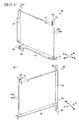
次に、画像表示装置5の前面に設けられている表示ユニット40の詳細な構造について説明する。図2は、(a)は表示ユニットを斜め前方から示す斜視図、(b)は表示ユニットを斜め後方から示す斜視図である。図3は、導光板とフレーム体とを分解して示す斜視図である。図4は、導光板とフレーム体との構造を示す分解斜視図である。なお、以下の説明においては、パチンコ遊技機1の正面に対峙した状態を基準として上下左右方向を説明する。   Next, the detailed structure of the display unit 40 provided on the front surface of the image display device 5 will be described. 2A is a perspective view showing the display unit obliquely from the front, and FIG. 2B is a perspective view showing the display unit obliquely from the rear. FIG. 3 is an exploded perspective view showing the light guide plate and the frame body. FIG. 4 is an exploded perspective view showing the structure of the light guide plate and the frame body. In the following description, the vertical and horizontal directions will be described with reference to the state facing the front of the pachinko gaming machine 1 as a reference.

図2から図4に示すように、表示ユニット40は、透明な2枚の導光板42(前導光板42A、後導光板42B)と、前導光板42A及び後導光板42Bを重ねて(対面させて)保持するフレーム体50と、前導光板42Aと後導光板42Bとのそれぞれに個別に光を出射可能な光出射部60と、から主に構成される。   As shown in FIGS. 2 to 4, the display unit 40 includes two transparent light guide plates 42 (a front light guide plate 42 </ b> A and a rear light guide plate 42 </ b> B), and a front light guide plate 42 </ b> A and a rear light guide plate 42 </ b> B that overlap (face each other). ) Mainly composed of a holding frame body 50 and a light emitting portion 60 capable of individually emitting light to each of the front light guide plate 42A and the rear light guide plate 42B.

図5は、(a)は前導光板を示す正面図、(b)は後導光板を示す正面図である。なお、図5には、光出射部60の集光レンズ62についても合わせて示している。導光板42は、所定の前後幅寸法L3(例えば5mm板厚など)を有するアクリルやポリカーボネートなどの透明な合成樹脂板で形成され、正面視横長長方形状に形成されている。前導光板42A及び後導光板42Bのそれぞれには、フレーム体50に取り付けるためのネジNを挿通させる複数の貫通孔43Aa〜43Af、43Ba〜43Bf(以下、まとめて貫通孔43ともいう)が形成されている。複数の貫通孔43のそれぞれは、導光板42における光出射部60からの光が入射される面(図5中、網掛部参照)から離れた位置に、つまり光出射部60の集光レンズ62が対向する位置とは異なる位置に形成されている。   5A is a front view showing the front light guide plate, and FIG. 5B is a front view showing the rear light guide plate. In FIG. 5, the condensing lens 62 of the light emitting unit 60 is also shown. The light guide plate 42 is formed of a transparent synthetic resin plate such as acrylic or polycarbonate having a predetermined front-rear width dimension L3 (for example, 5 mm plate thickness), and is formed in a horizontally long rectangular shape when viewed from the front. Each of the front light guide plate 42A and the rear light guide plate 42B is formed with a plurality of through holes 43Aa to 43Af and 43Ba to 43Bf (hereinafter collectively referred to as the through holes 43) through which screws N for attaching to the frame body 50 are inserted. ing. Each of the plurality of through holes 43 is located at a position away from the surface (see the shaded portion in FIG. 5) on the light guide plate 42 on which light from the light emitting portion 60 is incident, that is, the condenser lens 62 of the light emitting portion 60. Is formed at a position different from the facing position.

複数の貫通孔43のそれぞれは、前導光板42Aと後導光板42Bとで異なる位置となるように形成されている。この実施の形態では、図5に示すように、導光板42には、上縁、左縁、下縁のそれぞれに2つずつ貫通孔43が形成されており、前導光板42Aの上縁の2つの貫通孔43Aa、43Abのそれぞれは、後導光板42Bの上縁の2つの貫通孔43Ba、43Bbのそれぞれよりも右側に形成されている。また、前導光板42Aの左縁の2つの貫通孔43Ac、43Adは、後導光板42Bの左縁の2つの貫通孔43Bc、43Bdよりも上下方向の端側に形成されており、前導光板42Aの下縁の2つの貫通孔42Ae、42Afは、後導光板42Bの下縁の2つの貫通孔42Be、42Bfよりも右側に形成されている。さらに、前導光板42A及び後導光板42Bの上縁の2つの貫通孔43の間には切り欠き44A、44Bが形成されており、前導光板の切り欠き44Aは、後導光板の切り欠き44Bよりも右側に形成されている。   Each of the plurality of through-holes 43 is formed at different positions on the front light guide plate 42A and the rear light guide plate 42B. In this embodiment, as shown in FIG. 5, the light guide plate 42 is formed with two through holes 43 on each of the upper edge, the left edge, and the lower edge, and 2 on the upper edge of the front light guide plate 42A. Each of the through holes 43Aa and 43Ab is formed on the right side of each of the two through holes 43Ba and 43Bb on the upper edge of the rear light guide plate 42B. Further, the two through holes 43Ac and 43Ad on the left edge of the front light guide plate 42A are formed on the end side in the vertical direction with respect to the two through holes 43Bc and 43Bd on the left edge of the rear light guide plate 42B. The two through holes 42Ae and 42Af at the lower edge are formed on the right side of the two through holes 42Be and 42Bf at the lower edge of the rear light guide plate 42B. Furthermore, notches 44A and 44B are formed between the two through holes 43 on the upper edges of the front light guide plate 42A and the rear light guide plate 42B. The notches 44A on the front light guide plate are formed from the notches 44B on the rear light guide plate. Is also formed on the right side.

前導光板42A及び後導光板42Bは、予め定められた向き(組付姿勢、図3など参照)でフレーム体50に取り付けられるように設計されており、この向きに対して裏返したり、回転させたときには、貫通孔43の位置が元の位置からずれるように構成されている。例えば、前導光板42Aは、上縁と下縁に形成されている貫通孔43Aa、43Ab、43Ae、43Afのそれぞれが左右方向に見て互いに異なる位置に形成されている。同様に、後導光板42Bは、上縁と下縁に形成されている貫通孔43Ba、43Bb、43Be、43Bfのそれぞれが左右方向に見て互いに異なる位置に形成されている。また、前導光板42A及び後導光板42Bには、左下に切り欠き45が形成されており、この切り欠き45を基準にして、導光板42の向きを判断することができる。   The front light guide plate 42A and the rear light guide plate 42B are designed to be attached to the frame body 50 in a predetermined direction (assembling posture, see FIG. 3 and the like), and are turned over or rotated with respect to this direction. Sometimes, the position of the through-hole 43 is configured to deviate from the original position. For example, in the front light guide plate 42A, through holes 43Aa, 43Ab, 43Ae, and 43Af formed in the upper edge and the lower edge are formed at different positions when viewed in the left-right direction. Similarly, in the rear light guide plate 42B, through holes 43Ba, 43Bb, 43Be, and 43Bf formed in the upper edge and the lower edge are formed at different positions when viewed in the left-right direction. The front light guide plate 42A and the rear light guide plate 42B have a notch 45 formed in the lower left, and the orientation of the light guide plate 42 can be determined with reference to the notch 45.

なお、前導光板42Aと後導光板42Bとは、上縁、左縁、下縁に2つずつ貫通孔43が形成されるものに限定されず、上縁、左縁、下縁に1つずつ又は3つ以上ずつ貫通孔43が形成されてもよいし、異なる数の貫通孔43が形成されていてもよい。   The front light guide plate 42A and the rear light guide plate 42B are not limited to those having two through holes 43 on the upper edge, the left edge, and the lower edge, but one each on the upper edge, the left edge, and the lower edge. Alternatively, three or more through holes 43 may be formed, or a different number of through holes 43 may be formed.

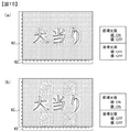
前導光板42A及び後導光板42Bには、光出射部60からの光によって発光する発光部46Aa、46Ab、46Ba、46Bbが形成されている。図6は、(a)は前導光板の表示パターンを示す図、(b)は後導光板の表示パターンを示す図、(c)は後導光板のドットパターンの一部を示す拡大図、(d)は裏面側のドットパターンでの光の反射を説明する断面図である。図6(a)に示すように、前導光板42Aの前面には、中央に「大当り」の文字が表れるように発光部46Aaが形成され(図6(a)中、実線参照)、前導光板42Aの背面には、前面の「大当り」の文字の上下両側に、「確変」の文字が表れるように発光部46Abが形成されている(図6(a)中、破線参照)。また、図6(b)に示すように、後導光板42Bの前面には、「チャンス」の文字が上下に2つずつ表れるとともに、左側中央に上に凸となる三角形の図形が、右側中央に下に凸となる三角形の図形が表れるように発光部が46Ba形成されている(図6(b)中、実線参照)。さらに、後導光板42Bの背面には、前面の「チャンス」に冠して「大」の文字が表れるとともに、前面の左側の三角形の図形に重なって下に凸となる三角形の図形が、前面の右側の三角形の図形に重なって上に凸となる三角形の図形が表れるように発光部46Bbが形成されている(図6(b)中、破線参照)。この実施の形態では、前導光板42A及び後導光板42Bに上下方向に沿って光が入射したときには、主に前面に形成された発光部46Aa、46Baが光を反射し、左右方向に沿って光が入射したときには、主に裏面に形成された発光部46Ab、46Bbが光を反射するように構成されている。このため、表示ユニット40では、前導光板42Aと後導光板42Bのそれぞれに対して、光出射部60により下側と左側とから光を出射することにより、計4種類の画像を表示することができる。   On the front light guide plate 42A and the rear light guide plate 42B, light emitting portions 46Aa, 46Ab, 46Ba, and 46Bb that emit light by light from the light emitting portion 60 are formed. 6A is a diagram showing a display pattern of the front light guide plate, FIG. 6B is a diagram showing a display pattern of the rear light guide plate, FIG. 6C is an enlarged view showing a part of the dot pattern of the rear light guide plate, d) is a cross-sectional view illustrating reflection of light by a dot pattern on the back surface side. As shown in FIG. 6A, a light emitting portion 46Aa is formed on the front surface of the front light guide plate 42A so that the letters “big hit” appear in the center (see the solid line in FIG. 6A). On the back surface of the, light-emitting portions 46Ab are formed on both the upper and lower sides of the “big hit” character on the front surface so that the characters “probability change” appear (see the broken line in FIG. 6A). Further, as shown in FIG. 6B, on the front surface of the rear light guide plate 42B, two “chance” characters appear at the top and bottom, and a triangular figure that protrudes upward in the center on the left side has a right center. A light emitting portion 46Ba is formed so that a triangular figure projecting downward appears (see a solid line in FIG. 6B). Further, on the back surface of the rear light guide plate 42B, a “large” character appears in front of the “chance” on the front surface, and a triangular figure that protrudes downward is superimposed on the triangular figure on the left side of the front surface. The light-emitting portion 46Bb is formed so that a triangular figure that protrudes upward is formed so as to overlap the triangular figure on the right side (see the broken line in FIG. 6B). In this embodiment, when light is incident on the front light guide plate 42A and the rear light guide plate 42B along the vertical direction, the light emitting portions 46Aa and 46Ba formed mainly on the front surface reflect the light, and light is emitted along the horizontal direction. When light enters, the light emitting portions 46Ab and 46Bb formed mainly on the back surface are configured to reflect light. For this reason, the display unit 40 can display a total of four types of images by emitting light from the lower side and the left side by the light emitting unit 60 with respect to each of the front light guide plate 42A and the rear light guide plate 42B. it can.

発光部46(発光部46Aa、46Ab、46Ba、46Bb)は、図6(c)、(d)に示すように、導光板42内を導光される光の進行方向の断面視が一定ピッチの略三角波形状をなす凹凸状態(粗面)に形成されている。また、前面に形成された発光部46Aa、46Baは、導光板42に上下方向に沿って入射した光によって発光するように横長に形成されており、背面に形成された発光部46Ab、46Bbは、導光板42に左右方向に沿って入射した光によって発光するように縦長に形成されている。発光部46は、具体的には、スタンパーやインジェクションにより導光板の表面に凹凸部をつける成型方式にて構成されているが、例えばアクリル板に白色インクで反射ドットを印刷したシルク印刷方式や、アクリル板と反射板とをドット状の粘着材で貼り付けた貼着ドット方式や、溝加工方式等により発光部を構成してもよい。   As shown in FIGS. 6C and 6D, the light emitting unit 46 (light emitting units 46Aa, 46Ab, 46Ba, 46Bb) has a constant pitch in a cross-sectional view in the traveling direction of light guided through the light guide plate 42. It is formed in an uneven state (rough surface) having a substantially triangular wave shape. Further, the light emitting portions 46Aa and 46Ba formed on the front surface are formed in a horizontally long shape so as to emit light by light incident on the light guide plate 42 along the vertical direction, and the light emitting portions 46Ab and 46Bb formed on the back surface are It is formed in a vertically long shape so as to emit light by light incident on the light guide plate 42 along the left-right direction. Specifically, the light emitting unit 46 is configured by a molding method in which an uneven portion is provided on the surface of the light guide plate by a stamper or injection. For example, a silk printing method in which reflective dots are printed with white ink on an acrylic plate, You may comprise a light emission part by the sticking dot system which affixed the acrylic board and the reflecting plate with the dot-shaped adhesive material, a groove processing system, etc. FIG.

なお、この実施の形態では、導光板42の発光部46を光の進行方向の断面視が略三角波形状の横長又は縦長の凹凸部としているが、本発明はこれに限定されるものではなく、これら発光部46の断面形状を略半円形状等、光を前面に向けて反射して導光板42に画像を表示するものであれば種々に変形可能である。なお、図6(a)、(b)などにおいて、発光部46は枠線で囲まれた文字や図柄として表されているが、実際には枠線はなく、上記ドット等の集まりによって文字や絵柄が形成されている。   In this embodiment, the light-emitting portion 46 of the light guide plate 42 is a horizontally or vertically concavo-convex portion having a substantially triangular wave shape in cross section in the light traveling direction, but the present invention is not limited to this, The light emitting section 46 can be variously modified as long as the cross-sectional shape of the light emitting portion 46 is a substantially semicircular shape or the like so as to reflect light toward the front and display an image on the light guide plate 42. In FIGS. 6A and 6B, the light emitting unit 46 is represented as a character or a pattern surrounded by a frame line. However, in actuality, there is no frame line. A pattern is formed.

また、この実施の形態では、導光板42によって表示可能とする画像(表示情報)として文字や図形が例示されているが、これら以外にも、記号、絵柄、あるいは模様などの装飾も含む他の画像を表示可能としてもよい。   Further, in this embodiment, characters and figures are illustrated as images (display information) that can be displayed by the light guide plate 42, but other than these, decorations such as symbols, patterns, patterns, etc. are also included. An image may be displayed.

フレーム体50は、非透光性を有する部材(例えば合成樹脂材など)で形成され、前導光板42A及び後導光板42Bと、光出射部60とを保持する。フレーム体50は、上フレーム52と、左フレーム54と、下フレーム56とからなり、各フレーム52、54、56には、表示ユニット40をパチンコ遊技機1に組み付けるための取付具58が設けられている。図7は、(a)は上フレームを下方から見た斜視図、(b)は上フレームの前側の差込溝より後方を前方から見た断面図、(c)は上フレームの後側の差込溝より後方を前方から見た断面図である。なお、図7および後述する図8、図9では、パチンコ遊技機1に組み付けるための取付具58の図示を省略している。図7に示すように、上フレーム52の内側面には、前後2つの差込溝52a,52bが長手方向に連続して、かつ平行に形成されている。上フレーム52の2つの差込溝52a,52bを隔てる隔壁52cには、前導光板42Aと後導光板42Bとに形成されている貫通孔43に対応した位置に、ネジ孔52dが形成されている。また、上フレーム52の前面には、前導光板42Aの貫通孔43に対応する位置に、ネジNを挿通させる凹部52eが形成されており(図7(a)参照)、背面には、後導光板42Bの貫通孔43に対応する位置に、ネジNを挿通させる凹部52fが形成されている(図7(a)(c)参照)。さらに、上フレーム52には、図7(b)に示すように、前側の差込溝52aに、前導光板42Aに形成されている切り欠き44Aに対応して凸部52gが形成され、後側の差込溝52bに、後導光板42Bに形成されている切り欠き44Bに対応して凸部52hが形成されている。なお、この実施の形態では、図7に示すように、上フレーム52の2つの差込溝52a、52bを隔てる隔壁52cには、ネジ孔52dが形成されている部分を除いて2つの差込溝52a、52bに平行する溝が中央に形成されており、上フレーム52の軽量化が図られている。ただし、上フレーム52の隔壁52cに、こうした溝が形成されなくてもよい。   The frame body 50 is formed of a non-translucent member (for example, a synthetic resin material), and holds the front light guide plate 42A, the rear light guide plate 42B, and the light emitting portion 60. The frame body 50 includes an upper frame 52, a left frame 54, and a lower frame 56. Each frame 52, 54, 56 is provided with a fixture 58 for assembling the display unit 40 to the pachinko gaming machine 1. ing. 7A is a perspective view of the upper frame as viewed from below, FIG. 7B is a sectional view of the rear of the upper frame as viewed from the front, and FIG. 7C is a rear view of the upper frame. It is sectional drawing which looked at the back from the insertion groove from the front. In addition, in FIG. 7 and FIG. 8, FIG. 9 mentioned later, illustration of the attachment tool 58 for assembling | attaching to the pachinko gaming machine 1 is omitted. As shown in FIG. 7, two front and rear insertion grooves 52 a and 52 b are formed on the inner surface of the upper frame 52 so as to be continuous in parallel with each other in the longitudinal direction. A screw hole 52d is formed at a position corresponding to the through hole 43 formed in the front light guide plate 42A and the rear light guide plate 42B in the partition wall 52c separating the two insertion grooves 52a and 52b of the upper frame 52. . In addition, a recess 52e through which the screw N is inserted is formed on the front surface of the upper frame 52 at a position corresponding to the through hole 43 of the front light guide plate 42A (see FIG. 7A). A recess 52f through which the screw N is inserted is formed at a position corresponding to the through hole 43 of the optical plate 42B (see FIGS. 7A and 7C). Further, as shown in FIG. 7B, the upper frame 52 is provided with a protrusion 52g in the front insertion groove 52a corresponding to the notch 44A formed in the front light guide plate 42A. A protrusion 52h is formed in the insertion groove 52b corresponding to the notch 44B formed in the rear light guide plate 42B. In this embodiment, as shown in FIG. 7, the partition 52c that separates the two insertion grooves 52a and 52b of the upper frame 52 has two insertions except for a portion where a screw hole 52d is formed. A groove parallel to the grooves 52a and 52b is formed in the center, and the weight of the upper frame 52 is reduced. However, such a groove may not be formed in the partition wall 52c of the upper frame 52.

図8は、(a)は左フレームを右側(中央側)から見た図、(b)は左フレームの前側の差込溝より後方を前方から見た断面図、(c)は左フレームの後側の差込溝より後方を前方から見た断面図である。図8に示すように、左フレーム54の内側(右側)の側面には、前後2つの差込溝54a、54bが上下方向に沿って平行に形成されている。2つの差込溝54a、54bのそれぞれは、上下方向の両端に、前導光板42A及び後導光板42Bと当接する底部55aが形成されており、上下方向の中央は左右方向に貫通する貫通孔55bとなっている。この貫通孔55bの上下端部には、上下中央に向けて突出するリブ55cが形成されるとともに、中央には、前後方向に隔壁54cを繋ぐ中央係止部55dが形成されており、光出射部60の集光レンズ62が左側(外側)から挿入される。貫通孔55bは、導光板42に向けて(外側から内側に)漸次前後幅寸法が小さくなるようにテーパ状に形成されている(図12参照)。左フレーム54の2つの差込溝54a、54bを隔てる隔壁54cには、前導光板42Aと後導光板42Bとに形成されている貫通孔43に対応した位置に、ネジ孔54dが形成されている。このネジ孔54dは、図8(b)に示すように、前導光板42A、後導光板42Bと当接する底部55aが形成されている部分の隔壁54cに形成されている。つまり、左フレーム54のネジ孔54dは、上下方向に、光出射部60の集光レンズ62から離れた位置に形成されている。また、左フレーム54の前面には、前導光板42Aの貫通孔43に対応する位置に、ネジを挿通させる凹部54e(図8(a)参照)が形成されており、背面には、後導光板42Bの貫通孔43に対応する位置に、ネジを挿通させる凹部54fが形成されている(図8(a)、(c)参照)。   8A is a view of the left frame as viewed from the right side (center side), FIG. 8B is a cross-sectional view of the left frame as viewed from the front side, and FIG. 8C is a view of the left frame. It is sectional drawing which looked at the back from the insertion slot of the rear side from the front. As shown in FIG. 8, two front and rear insertion grooves 54 a and 54 b are formed in parallel in the vertical direction on the inner (right) side surface of the left frame 54. Each of the two insertion grooves 54a and 54b has a bottom 55a that contacts the front light guide plate 42A and the rear light guide plate 42B at both ends in the vertical direction, and the center in the vertical direction is a through hole 55b that penetrates in the left and right direction. It has become. At the upper and lower ends of the through hole 55b, ribs 55c projecting toward the center in the vertical direction are formed, and at the center, a central locking portion 55d that connects the partition wall 54c in the front-rear direction is formed. The condenser lens 62 of the unit 60 is inserted from the left side (outside). The through-hole 55b is formed in a tapered shape so that the front-rear width dimension gradually decreases toward the light guide plate 42 (from the outside to the inside) (see FIG. 12). A screw hole 54d is formed at a position corresponding to the through hole 43 formed in the front light guide plate 42A and the rear light guide plate 42B in the partition wall 54c separating the two insertion grooves 54a and 54b of the left frame 54. . As shown in FIG. 8B, the screw hole 54d is formed in a partition wall 54c where a bottom portion 55a that contacts the front light guide plate 42A and the rear light guide plate 42B is formed. That is, the screw hole 54d of the left frame 54 is formed at a position away from the condenser lens 62 of the light emitting unit 60 in the vertical direction. Further, a recess 54e (see FIG. 8A) through which a screw is inserted is formed on the front surface of the left frame 54 at a position corresponding to the through hole 43 of the front light guide plate 42A, and the rear light guide plate is formed on the rear surface. A recess 54f through which a screw is inserted is formed at a position corresponding to the through hole 43 of 42B (see FIGS. 8A and 8C).

図9は、(a)は下フレームを上側(中央側)から見た図、(b)は下フレームの前側の差込溝より後方を前方から見た断面図、(c)は下フレームの後側の差込溝より後方を前方から見た断面図である。図7に示すように、下フレーム56の内側(上側)の側面には、前後2つの差込溝56a、56bが左右方向に沿って形成されている。2つの差込溝56a、56bのそれぞれは、左右方向の両端に前導光板42A、後導光板42Bと当接する底部57aが形成されており、左右方向の中央は上下方向に貫通する貫通孔57bとなっている。この貫通孔57bの左右端部には、左右方向の中央に向けて突出するリブ57cが形成されるとともに、中央には、前後方向に隔壁56cを繋ぐ中央係止部57dが2箇所に形成されており、光出射部60の集光レンズ62が下側(外側)から挿入される。この実施の形態では、下フレーム56の前側に収容される集光レンズ62は、後側に収容される集光レンズ62よりも長手方向に短く構成されており、前側の差込溝56aの貫通孔57aは、集光レンズ62の形状に合わせて左右方向に短く、つまりリブ57c同士の間が狭く形成されている。また、集光レンズ62の形状に合わせて、前側の差込溝56aの中央係止部57dは、後側の差込溝56bの中央係止部57dよりも間隔が狭く形成されている。下フレーム56の2つの差込溝56a、56bを隔てる隔壁56cには、前導光板42Aと後導光板42Bとに形成されている貫通孔43に対応した位置に、ネジ孔56dが形成されている。このネジ孔56dは、図7(b)に示すように、前導光板42A、後導光板42Bと当接する底部57aが形成されている部分の隔壁56cに形成されている。つまり、下フレーム56のネジ孔56dは、左右方向に、光出射部60の集光レンズ62から離れた位置に形成されている。また、下フレーム56の前面には、前導光板42Aの貫通孔43に対応する位置に、ネジを挿通させる凹部56eが形成されており、背面には、後導光板42Bの貫通孔43に対応する位置に、ネジを挿通させる凹部56fが形成されている。   9A is a view of the lower frame as viewed from the upper side (center side), FIG. 9B is a sectional view of the lower frame as viewed from the front side from the insertion groove on the front side, and FIG. 9C is a view of the lower frame. It is sectional drawing which looked at the back from the insertion slot of the rear side from the front. As shown in FIG. 7, front and rear insertion grooves 56 a and 56 b are formed along the left-right direction on the inner (upper) side surface of the lower frame 56. Each of the two insertion grooves 56a and 56b has a bottom portion 57a that contacts the front light guide plate 42A and the rear light guide plate 42B at both ends in the left and right direction, and the center in the left and right direction is a through hole 57b that penetrates in the vertical direction. It has become. At the left and right ends of the through hole 57b, ribs 57c projecting toward the center in the left-right direction are formed, and at the center, two central locking portions 57d that connect the partition walls 56c in the front-rear direction are formed. The condenser lens 62 of the light emitting unit 60 is inserted from the lower side (outer side). In this embodiment, the condensing lens 62 accommodated in the front side of the lower frame 56 is configured to be shorter in the longitudinal direction than the condensing lens 62 accommodated in the rear side, and penetrates through the front insertion groove 56a. The holes 57a are short in the left-right direction according to the shape of the condenser lens 62, that is, the gaps between the ribs 57c are narrowly formed. Further, in accordance with the shape of the condenser lens 62, the central locking portion 57d of the front insertion groove 56a is formed to be narrower than the central locking portion 57d of the rear insertion groove 56b. A screw hole 56d is formed at a position corresponding to the through hole 43 formed in the front light guide plate 42A and the rear light guide plate 42B in the partition wall 56c separating the two insertion grooves 56a and 56b of the lower frame 56. . As shown in FIG. 7B, the screw hole 56d is formed in a partition wall 56c at a portion where a bottom portion 57a that contacts the front light guide plate 42A and the rear light guide plate 42B is formed. That is, the screw hole 56d of the lower frame 56 is formed at a position away from the condenser lens 62 of the light emitting unit 60 in the left-right direction. Further, a recess 56e through which a screw is inserted is formed on the front surface of the lower frame 56 at a position corresponding to the through hole 43 of the front light guide plate 42A, and on the back surface, the recess 56e corresponds to the through hole 43 of the rear light guide plate 42B. A recess 56f for inserting a screw is formed at the position.

図4及び図7から図9に示すように、この実施の形態の前導光板42Aと後導光板42Bとのそれぞれは、フレーム体50との取り付けのための貫通孔43が互いに異なる位置に形成されているので、前導光板42Aをフレーム体50の後側の差込溝52b、54b、56bに差し込んで取り付けようとした場合には、フレーム体50の背面に形成されたネジ止め凹部52f、54f、56fと前導光板42Aの貫通孔43との位置が合わないため前導光板42Aをフレーム体50に取り付けることができず、後導光板42Bをフレーム体50の前側の差込溝52a、54a、56aに差し込んで取り付けようとした場合には、フレーム体50の前面に形成されたネジ止め凹部52e、54e、56eと後導光板42Aの貫通孔43の位置が合わないため後導光板42Aをフレーム体50に取り付けることができない。したがって、前導光板42Aと後導光板42Bとフレーム体50との組み付け間違いを防止することができ、導光板42とフレーム体50とを容易に組み付けることができる。しかも、前導光板42Aと後導光板42Bとのそれぞれは、前導光板42Aと後導光板42Bを予め定められた組付姿勢(図3など参照)に対して裏返したり、回転させたときには、貫通孔43の位置がずれるように構成されており、予め定められた組付姿勢に対して裏返したり、回転させたときには、フレーム体50におけるネジ止めをするためのネジ孔54d、56dやネジ止め凹部55c、57cと位置が対応しないように構成されているので、前導光板42Aや後導光板42Bを裏返したり回転させた状態で前導光板42や後導光板42Bとフレーム体50とを組み付けてしまうのを防止することができる。   As shown in FIGS. 4 and 7 to 9, in each of the front light guide plate 42 </ b> A and the rear light guide plate 42 </ b> B of this embodiment, through holes 43 for attachment to the frame body 50 are formed at different positions. Therefore, when the front light guide plate 42A is inserted into the insertion grooves 52b, 54b, 56b on the rear side of the frame body 50 to be attached, screwing recesses 52f, 54f formed on the back surface of the frame body 50, Since the positions of 56f and the through hole 43 of the front light guide plate 42A are not aligned, the front light guide plate 42A cannot be attached to the frame body 50, and the rear light guide plate 42B is inserted into the insertion grooves 52a, 54a, 56a on the front side of the frame body 50. When trying to insert and attach, the positions of the screw recesses 52e, 54e, 56e formed on the front surface of the frame body 50 and the through hole 43 of the rear light guide plate 42A are It is impossible to attach the rear light guide plate 42A to the frame member 50 for not adversely. Therefore, it is possible to prevent an assembly error between the front light guide plate 42A, the rear light guide plate 42B, and the frame body 50, and the light guide plate 42 and the frame body 50 can be easily assembled. Moreover, each of the front light guide plate 42A and the rear light guide plate 42B has a through hole when the front light guide plate 42A and the rear light guide plate 42B are turned over or rotated with respect to a predetermined assembly posture (see FIG. 3 and the like). 43, the screw holes 54d and 56d for screwing in the frame body 50 and screwing recesses 55c when turned over or rotated with respect to a predetermined mounting posture. 57c, the positions of the front light guide plate 42A and the rear light guide plate 42B are turned over or rotated, and the front light guide plate 42 or the rear light guide plate 42B and the frame body 50 are assembled. Can be prevented.

また、この実施の形態のフレーム体50は、前導光板42A及び後導光板42Bを上側から保持する上フレーム52と、前導光板42A及び後導光板42Bを左側から保持する左フレーム54と、前導光板42A及び後導光板42Bを下側から保持する下フレーム56との複数のフレームで構成され、前導光板42A及び後導光板42Bは、上フレーム52、左フレーム54、下フレーム56の各フレームに取り付けるための貫通孔43のそれぞれが、前導光板42Aと後導光板42Bとで異なる位置に形成されている。このため、上フレーム52、左フレーム54、下フレーム56のそれぞれに対して、前導光板42Aと後導光板42Bとの組み付け間違いを防止することができる。さらに、前導光板42A及び後導光板42Bは、前導光板42Aと後導光板42Bを予め定められた組付姿勢(図3など参照)に対して裏返したり、回転させたときには、上フレーム52、左フレーム54、下フレーム56の各フレームに取り付けるための貫通孔43のそれぞれの位置がずれるように構成されており、上フレーム52、左フレーム54、下フレーム56の各フレームについて、前導光板42Aや後導光板42Bを裏返したり回転させた状態で前導光板42や後導光板42Bとフレーム体50とを組み付けてしまうのを防止することができる。   Further, the frame body 50 of this embodiment includes an upper frame 52 that holds the front light guide plate 42A and the rear light guide plate 42B from the upper side, a left frame 54 that holds the front light guide plate 42A and the rear light guide plate 42B from the left side, and the front light guide plate. The front light guide plate 42A and the rear light guide plate 42B are attached to the upper frame 52, the left frame 54, and the lower frame 56, respectively. Each of the through-holes 43 is formed at a different position between the front light guide plate 42A and the rear light guide plate 42B. For this reason, it is possible to prevent an assembly error between the front light guide plate 42A and the rear light guide plate 42B for each of the upper frame 52, the left frame 54, and the lower frame 56. Further, when the front light guide plate 42A and the rear light guide plate 42B are turned over or rotated with respect to a predetermined assembly posture (see FIG. 3 or the like), the front light guide plate 42A and the rear light guide plate 42B The positions of the through holes 43 to be attached to the respective frames 54 and 56 are configured to be shifted, and the front light guide plate 42 </ b> A and the rear frame of each of the upper frame 52, the left frame 54, and the lower frame 56 are configured. It is possible to prevent the front light guide plate 42 or the rear light guide plate 42B and the frame body 50 from being assembled in a state where the light guide plate 42B is turned over or rotated.

また、フレーム体50は、上フレーム52、左フレーム54、下フレーム56の3つの部材で構成されるものに限定されず、例えば、上フレーム52を備えずに左フレーム54、下フレーム56とでフレーム体50が構成されてもよいし、各フレーム52、54、56が一体に形成されてもよい。   Further, the frame body 50 is not limited to the three members of the upper frame 52, the left frame 54, and the lower frame 56. For example, the frame body 50 includes the left frame 54 and the lower frame 56 without the upper frame 52. The frame body 50 may be configured, or the frames 52, 54, and 56 may be formed integrally.

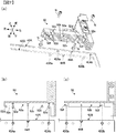
光出射部60は、フレーム体50の左フレーム54と下フレーム54のそれぞれに取り付けられて支持される。図4に示すように、光出社部60は、表示用LED67が複数取り付けられたLED基板66と、表示用LED67からの光を前導光板42A及び後導光板42Bに案内する集光レンズ62とを有する。図10は、(a)は集光レンズの正面図、(b)は集光レンズの平面図、(c)は(a)のA−A断面図、(d)は(a)のB−B断面図である。図11は、(a)は下フレームを示す要部拡大断面図、(b)は(a)のC−C断面図、(c)は(a)のD−D断面図である。   The light emitting unit 60 is attached to and supported by each of the left frame 54 and the lower frame 54 of the frame body 50. As shown in FIG. 4, the light office 60 includes an LED substrate 66 on which a plurality of display LEDs 67 are attached, and a condensing lens 62 that guides light from the display LEDs 67 to the front light guide plate 42A and the rear light guide plate 42B. Have. 10A is a front view of the condenser lens, FIG. 10B is a plan view of the condenser lens, FIG. 10C is a cross-sectional view taken along the line AA in FIG. 10A, and FIG. It is B sectional drawing. 11A is an enlarged cross-sectional view of the main part showing the lower frame, FIG. 11B is a cross-sectional view taken along the line CC of FIG. 11A, and FIG. 11C is a cross-sectional view taken along the line DD of FIG.

集光レンズ62は、アクリルまたはポリカーボネート等の透光性を有する部材(例えば合成樹脂材など)によって長尺板状に形成される。集光レンズ62は、正面視で前導体板42Aおよび後導体板42B側(内側)に膨出する略半円形状の複数の凸部62aが長手方向に連続して並接されている。各凸部62aは、表示用LED67のそれぞれに対応して1つずつ形成され、各凸部62aの先端面、つまり、集光レンズ62における前導光板42A及び後導光板42Bに対向する面(出射面)には、複数の湾曲面(レンズ面)を構成している。また、集光レンズ62には、フレーム体50のリブ55c、57cと当接するフック片62bがの長手方向の両端に設けられるとともに、フレーム体50の中央係止部55d、57dと当接する係子凹部62cが、中央係止部55d、57dに対応して設けられている(図8、図9参照)。   The condensing lens 62 is formed in a long plate shape by a translucent member such as acrylic or polycarbonate (for example, a synthetic resin material). In the condenser lens 62, a plurality of substantially semicircular convex portions 62a bulging toward the front conductor plate 42A and the rear conductor plate 42B (inner side) in front view are continuously juxtaposed in the longitudinal direction. Each convex portion 62a is formed one by one corresponding to each of the display LEDs 67, and the front end surface of each convex portion 62a, that is, the surface facing the front light guide plate 42A and the rear light guide plate 42B in the condenser lens 62 (outgoing light). A plurality of curved surfaces (lens surfaces). Further, the condenser lens 62 is provided with hook pieces 62b that come into contact with the ribs 55c and 57c of the frame body 50 at both ends in the longitudinal direction, and an engaging member that comes into contact with the central locking portions 55d and 57d of the frame body 50. The recessed part 62c is provided corresponding to the center latching | locking parts 55d and 57d (refer FIG. 8, FIG. 9).

なお、複数の凸部62aは表示用LEDのそれぞれに対応に一体一に対応するものに限らず、例えば2以上のLED(発光体)に対応する凸部(レンズ面)が複数設けられていてもよい。また、集光レンズ62は、複数の凸部62aが一体に設けられた単一の部材にて構成されるものとしたが、LED(発光体)に対応して別個に形成された複数の集光レンズを用いてもよい。   The plurality of convex portions 62a are not limited to one corresponding to each of the display LEDs, and for example, a plurality of convex portions (lens surfaces) corresponding to two or more LEDs (light emitters) are provided. Also good. Further, although the condenser lens 62 is constituted by a single member integrally provided with a plurality of convex portions 62a, a plurality of condenser lenses separately formed corresponding to the LEDs (light emitting bodies) are used. An optical lens may be used.

集光レンズ62の表示用LED側(外側)の面には、正面視で外側に僅かに膨張する湾曲形状の膨出部62eが長手方向に複数連続して形成されている。各膨出部62eは、表示用LEDの各々に対応して1つずつ形成され、各膨出部62eの先端面、つまり集光レンズ62における表示用LED67に対向する面(入射面)は、複数の湾曲面(レンズ面)を構成している。なお、表示用LED67に対向する湾曲面は、前導光板42A及び後導光板42Bに対向する湾曲面に比べて曲率は小さく、僅かに膨出する程度に形成されている。   On the display LED side (outside) surface of the condenser lens 62, a plurality of curved bulging portions 62e that slightly bulge outward in a front view are continuously formed in the longitudinal direction. Each bulging portion 62e is formed one by one corresponding to each of the display LEDs, and the tip surface of each bulging portion 62e, that is, the surface (incident surface) facing the display LED 67 in the condenser lens 62 is A plurality of curved surfaces (lens surfaces) are formed. The curved surface facing the display LED 67 has a smaller curvature than the curved surfaces facing the front light guide plate 42A and the rear light guide plate 42B, and is formed so as to slightly bulge.

また、集光レンズ62は、前導光板42A及び後導光板42Bに対向する面の前後幅寸法L1(板厚)は、表示用LEDに対向する面の前後幅寸法L2(板厚)よりも短寸とされている(L1<L2)。また、集光レンズ62における前導光板42A及び後導光板42Bに対向する面の前後幅寸法L1は、前導光板42A及び後導光板42Bの前後幅寸法L3とほぼ同寸とされ(L1≒L3)、集光レンズ62における表示用LED67に対向する面の前後幅寸法L2は、表示用LED67の発光面67aの前後幅寸法L4(図12参照)とほぼ同寸に形成されている(L2≒L4)。   Further, in the condensing lens 62, the front-rear width dimension L1 (plate thickness) of the surface facing the front light guide plate 42A and the rear light guide plate 42B is shorter than the front-rear width dimension L2 (plate thickness) of the surface facing the display LED. It is set as a dimension (L1 <L2). Further, the front-rear width dimension L1 of the surface facing the front light guide plate 42A and the rear light guide plate 42B in the condenser lens 62 is substantially the same as the front and rear width dimension L3 of the front light guide plate 42A and the rear light guide plate 42B (L1≈L3). The front-rear width dimension L2 of the surface of the condenser lens 62 facing the display LED 67 is substantially the same as the front-rear width dimension L4 (see FIG. 12) of the light emitting surface 67a of the display LED 67 (L2≈L4). ).

そして、集光レンズ62は、表示用LED67側から前導光板42A及び後導光板42B側(外側から内側)に向けて、前面62Fが漸次後側に傾斜する平坦な傾斜面を構成するとともに、背面62Bが漸次前側に傾斜する平坦な傾斜面を構成している。つまり、集光レンズ62は、表示用LED67側から前導光板42A及び後導光板42B側に向けて漸次板厚が薄くなるテーパ状に形成されている。なお、この実施の形態では、集光レンズ62は、表示用LED側(外側)の端部に、板厚が均一な短寸の非傾斜部62fが設けられている。   The condensing lens 62 constitutes a flat inclined surface in which the front surface 62F gradually inclines toward the rear side from the display LED 67 side toward the front light guide plate 42A and the rear light guide plate 42B (from the outside to the inside). 62B constitutes a flat inclined surface that gradually inclines forward. That is, the condensing lens 62 is formed in a tapered shape in which the plate thickness gradually decreases from the display LED 67 side toward the front light guide plate 42A and the rear light guide plate 42B. In this embodiment, the condensing lens 62 is provided with a short non-inclined portion 62f having a uniform thickness at the end of the display LED side (outside).

図4や図11に示すように、このように構成された集光レンズ62は、左フレーム54や下フレーム56の貫通孔55b、57bに外側から差し込まれ、外側の面が左フレーム54や下フレーム56の外側の面とほぼ面一となる位置まで差し込まれると、集光レンズ62のフック片62bが左フレーム54や下フレーム56のリブ55c、57cに当接する。この状態で、外側からLED基板66がフレーム体50にネジ止めされることによって、集光レンズ62は、前後に所定の隙間を隔ててフレーム体50に保持される。このように光出射部60がフレーム体50に保持されることによって、フレーム体50に取り付けられる導光板42と光出射部60との位置ずれを防止することができる。しかも、この実施の形態では、集光レンズ62は、フック片62bが左フレーム54や下フレーム56のリブ55c、57cに当接するとともに、集光レンズ62の係止凹部62cと左フレーム54や下フレーム56の中央係止部57dとが係止されるので、集光レンズ62とフレーム体50との位置ずれを防止することができる。   As shown in FIGS. 4 and 11, the condensing lens 62 configured in this way is inserted into the through holes 55b and 57b of the left frame 54 and the lower frame 56 from the outside, and the outer surface is the left frame 54 and the lower frame. When inserted to a position that is substantially flush with the outer surface of the frame 56, the hook pieces 62 b of the condenser lens 62 abut against the ribs 55 c and 57 c of the left frame 54 and the lower frame 56. In this state, the LED substrate 66 is screwed to the frame body 50 from the outside, whereby the condenser lens 62 is held by the frame body 50 with a predetermined gap in the front and rear direction. As described above, the light emitting unit 60 is held by the frame body 50, thereby preventing the positional deviation between the light guide plate 42 attached to the frame body 50 and the light emitting unit 60. Moreover, in this embodiment, the condensing lens 62 has the hook piece 62b abutting against the ribs 55c and 57c of the left frame 54 and the lower frame 56, and the locking recess 62c of the condensing lens 62 and the left frame 54 and the lower frame. Since the center locking portion 57d of the frame 56 is locked, it is possible to prevent the positional deviation between the condenser lens 62 and the frame body 50.

また、集光レンズ62は、表示用LED67側の面の前後幅寸法L2と表示用LED62の発光面67aの前後幅寸法L4とがほぼ同寸のため(L2≒L4)、表示用LED67からの出射光は前後方向に拡散されることなく集光レンズ62に入射される。さらに、集光レンズ62は、導光板42側の面の前後幅寸法L1と導光板42の前後幅寸法L3とがほぼ同寸のため(L1≒L3)、集光レンズ62からの出射光は前後方向に拡散されることなく導光板42に入射される。   Further, in the condenser lens 62, the front-rear width dimension L2 of the surface on the display LED 67 side and the front-rear width dimension L4 of the light emitting surface 67a of the display LED 62 are almost the same dimension (L2≈L4). The emitted light enters the condenser lens 62 without being diffused in the front-rear direction. Further, since the front-rear width dimension L1 of the surface on the light guide plate 42 side and the front-rear width dimension L3 of the light guide plate 42 of the condenser lens 62 are substantially the same (L1≈L3), the light emitted from the condenser lens 62 is The light is incident on the light guide plate 42 without being diffused in the front-rear direction.

また、この実施の形態では、フレーム体50に集光レンズ62と導光板42とが取り付けられたときには、集光レンズ62と導光板42との間に若干(例えば、約1mm〜3mm程度など)の隙間が設けられる。これにより、パチンコ遊技機1の輸送や使用の際に生じる振動によって集光レンズ62や導光板42に傷が付くことを防止することができる。   In this embodiment, when the condensing lens 62 and the light guide plate 42 are attached to the frame body 50, a slight amount (for example, about 1 mm to 3 mm) is provided between the condensing lens 62 and the light guide plate 42. Is provided. Thereby, it is possible to prevent the condensing lens 62 and the light guide plate 42 from being damaged by vibrations generated during transportation and use of the pachinko gaming machine 1.

次に、表示用LED67からの出射光の導光状態について説明する。図12は、表示ユニットの縦断面を示す要部拡大断面図である。図13は、(a)は下方の光出射部が駆動されたときの後導光板の表示パターンを示す模式図、(b)は左方の光出射部が駆動されたときの後導光板の表示パターンを示す模式図である。図12及び図13に示すように、各表示用LED67から出射された出射光は、集光レンズ62に入射される。ここで、集光レンズ62の表示用LED側の面の前後幅寸法L2と、表示用LEDの発光面67aの前後幅寸法L4とはほぼ同寸であるため(L2≒L4)、各表示用LED67からの出射光は、前後方向に拡散せずにほぼ集光レンズ62内に入射する。LEDの光は指向性が高いが、集光レンズ62の入射面62eは、レンズ面をなすように湾曲状に形成されているので、集光レンズ62への入射光は、集光レンズ62内で左右方向に放射状に拡散される。そして、入射光は、内側(導光板側)の湾曲状のレンズ面を通過する際に、下フレーム56に支持された光出射部60では上方向(鉛直方向)に向けて屈折し(図13(a)参照)、左フレーム54に支持された光出射部60では右方向(水平方向)に向けて屈折して出射される(図13(b)参照)。   Next, the light guide state of the emitted light from the display LED 67 will be described. FIG. 12 is an enlarged cross-sectional view of a main part showing a vertical cross section of the display unit. 13A is a schematic diagram showing a display pattern of the rear light guide plate when the lower light emitting portion is driven, and FIG. 13B is a diagram of the rear light guide plate when the left light emitting portion is driven. It is a schematic diagram which shows a display pattern. As shown in FIGS. 12 and 13, the emitted light emitted from each display LED 67 is incident on the condenser lens 62. Here, since the front-rear width dimension L2 of the surface of the condenser lens 62 on the display LED side and the front-rear width dimension L4 of the light emitting surface 67a of the display LED are substantially the same dimension (L2≈L4), The light emitted from the LED 67 is substantially diffused into the condenser lens 62 without being diffused in the front-rear direction. Although the light from the LED has high directivity, the incident surface 62e of the condenser lens 62 is formed in a curved shape so as to form a lens surface. Is diffused radially in the horizontal direction. Then, when the incident light passes through the curved lens surface on the inner side (light guide plate side), the incident light is refracted upward (vertical direction) in the light emitting portion 60 supported by the lower frame 56 (FIG. 13). (See (a)), the light emitting unit 60 supported by the left frame 54 refracts and emits rightward (horizontal direction) (see FIG. 13B).

これにより、指向性が高い表示用LEDからの出射光を、集光レンズ62によってある程度放射状に拡散させることができ、導光板42における発光領域を広げることが可能となる。また、集光レンズ62から出射される光は、鉛直方向または水平方向に向けて誘導されて放射状に拡がることはないので、各表示用LED67に対応する領域のみを部分的に発光させることができる。   Thereby, the emitted light from the display LED having high directivity can be diffused radially to some extent by the condenser lens 62, and the light emitting region in the light guide plate 42 can be widened. Further, since the light emitted from the condenser lens 62 is guided in the vertical direction or the horizontal direction and does not spread radially, only the region corresponding to each display LED 67 can be caused to emit light partially. .

また、図13に示すように、表示用LED67から集光レンズ62に入射された入射光は、前後(板厚)方向に全反射を繰り返し、前後方向の略中央位置に向けて集光され、最終的に前後幅が小さい導光板42側の端面から出射される。   In addition, as shown in FIG. 13, the incident light incident on the condenser lens 62 from the display LED 67 repeats total reflection in the front-rear (plate thickness) direction, and is condensed toward a substantially central position in the front-rear direction. Finally, the light is emitted from the end surface on the light guide plate 42 side having a small front-rear width.

このように、表示用LED67からの光を前後幅(板厚)方向に拡散させることなく集光して導光板42から出射させることができるので、光の減衰が抑制される。特に、表示用LEDの発光面67aの前後幅寸法L4が、集光レンズ62における表示用LED側端部の前後幅寸法L2よりも大きい場合(L4>L2)であっても、表示用LED67からの光を前後幅(板厚)方向に拡散させることなく導光板42に導くことができるので、表示用LED67からの光が周囲に拡散されることが防止される。   As described above, the light from the display LED 67 can be collected without being diffused in the front-rear width (plate thickness) direction and emitted from the light guide plate 42, so that attenuation of light is suppressed. In particular, even when the front-rear width dimension L4 of the light emitting surface 67a of the display LED is larger than the front-rear width dimension L2 of the display LED side end portion of the condenser lens 62 (L4> L2), Can be guided to the light guide plate 42 without being diffused in the front-rear width (plate thickness) direction, so that the light from the display LED 67 is prevented from diffusing to the surroundings.

また、特に図示しないが、例えば表示用LED67が前後幅方向に複数配置される場合でも、集光レンズ62における表示用LED67側の前後幅寸法L2を表示用LEDに応じて拡げ、これにより出射光を周囲に拡散させずに集光レンズ62に入射さえることができる。よって、導光板42の前後幅寸法(板厚)L3よりも表示用LED67の発光領域の前後幅寸法が大きい場合でも、表示用LED67からの出射光を誘導しながら板厚方向に集光して導光板42に入射させることができる。   Although not particularly illustrated, for example, even when a plurality of display LEDs 67 are arranged in the front-rear width direction, the front-rear width dimension L2 on the display LED 67 side of the condensing lens 62 is expanded in accordance with the display LEDs, thereby emitting light. Can be incident on the condenser lens 62 without being diffused to the surroundings. Therefore, even when the front-rear width dimension of the display LED 67 is larger than the front-rear width dimension (plate thickness) L3 of the light guide plate 42, the light emitted from the display LED 67 is condensed in the thickness direction while guiding the emitted light. The light can be incident on the light guide plate 42.

集光レンズ67から導光板42に光が出射され、発光部46に光が到達すると、発光部46にて光が前面側に向けて反射されることで、遊技者からは、それぞれの発光部46に対応する箇所が反射光により発光されることで、所定の文字や図形などの画像(表示情報)が表示されるようになる。   When light is emitted from the condensing lens 67 to the light guide plate 42 and reaches the light emitting unit 46, the light is reflected toward the front side by the light emitting unit 46, so that each light emitting unit is received from the player. A portion corresponding to 46 is emitted by reflected light, so that an image (display information) such as a predetermined character or figure is displayed.

表示ユニット40による表示演出の一例を説明する。パチンコ遊技機1では、例えばリーチ演出や大当り演出が行われるときに、特図変動時演出制御パターンに従って表示ユニット40による演出演出が行われる。図14及び図15は、表示ユニットの表示制御の一例である。例えば、パチンコ遊技機1が備えるコンピュータによって、下フレーム56に取り付けられた後導光板42Bに対応する光出射部60の表示用LED67を点灯させることで、「チャンス」の文字と三角形の図形が表示され(図14(a)参照)、続いて左フレーム54に取り付けられた後導光板42Bに対応する光出射部60の表示用LED67を点灯させることで「チャンス」に冠する「大」の文字と、前面側の三角形に重なる三角形の図形とが表示される(図14(b)参照)。そして、大当り演出として、下フレーム56に取り付けられた前導光板42Aに対応する光出射部60の表示用LED67を点灯させることで「大当り」の文字が表示される(図14(c)参照)。   An example of the display effect by the display unit 40 will be described. In the pachinko gaming machine 1, for example, when a reach effect or a jackpot effect is performed, an effect effect by the display unit 40 is performed according to the special-fluctuation effect control pattern. 14 and 15 are examples of display control of the display unit. For example, the computer of the pachinko gaming machine 1 displays the letters “chance” and a triangular figure by turning on the display LED 67 of the light emitting unit 60 corresponding to the light guide plate 42B after being attached to the lower frame 56. (See FIG. 14 (a)), followed by turning on the display LED 67 of the light emitting section 60 corresponding to the rear light guide plate 42B attached to the left frame 54, and the word “Large” And a triangular figure that overlaps with the triangle on the front side are displayed (see FIG. 14B). Then, as a big hit effect, by turning on the display LED 67 of the light emitting unit 60 corresponding to the front light guide plate 42A attached to the lower frame 56, the character of "big hit" is displayed (see FIG. 14C).

また、例えば、表示ユニット40に「大当り」の文字だけが表示されている状態で(図15(a)参照)、続いて左フレーム54に取り付けられた前導光板42Aに対応する光出射部60の表示用LED67を点灯させることで、「大当り」の文字の上下に「確変」の文字が表示される(図15(b)参照)。   Further, for example, in a state where only the character “big hit” is displayed on the display unit 40 (see FIG. 15A), the light emitting unit 60 corresponding to the front light guide plate 42 </ b> A attached to the left frame 54 subsequently. By turning on the display LED 67, the characters “probability change” are displayed above and below the characters “big hit” (see FIG. 15B).

このように、前後の導光板42Aの前面と背面とのそれぞれに対応する表示用LED67を個別に表示制御可能とすることで、1枚の導光板を用いたり、2枚の導光板の前面と背面との一方だけを用いたりする場合に比べて、表示のバリエーションを増やすことができる。このため、多彩な表示パターンでの表示が可能となる。   In this way, the display LEDs 67 corresponding to the front and back surfaces of the front and rear light guide plates 42A can be individually controlled to display one light guide plate or the front surfaces of the two light guide plates. As compared with the case where only one of the rear side and the rear side is used, display variations can be increased. For this reason, display in various display patterns is possible.

ここで、リーチ演出における表示ユニット40を用いた演出動作では、大当り期待度が高いリーチ演出のときほど、演出効果の高い演出動作が行われるように予め演出パターンを定めておいてもよい。例えば、ノーマルリーチ演出が行われるときには、表示ユニットに「チャンス」の文字だけが表され(図14(a)参照)、スーパーリーチ演出が行われるときには、「チャンス」の文字に冠して、「大」の文字が表されるように演出制御を行うなどとしてもよい(図14(b)参照)。   Here, in the production operation using the display unit 40 in the reach production, the production pattern may be determined in advance so that the production operation having a higher production effect is performed as the reach production has a higher degree of expectation of jackpot. For example, when the normal reach effect is performed, only the word “chance” is displayed on the display unit (see FIG. 14A), and when the super reach effect is performed, the character “chance” is added to “large”. Production control may be performed so that the characters "" are represented (see FIG. 14B).

なお、表示ユニット40を用いた演出動作については、これらの例に限定されるものではなく、光出射部60を駆動することによって実現できる種々の演出動作が採用されればよい。また、リーチ演出や大当り演出以外の演出において、表示ユニット40を用いた演出動作が行われてもよい。例えば、リーチ演出とは異なり、飾り図柄の可変表示状態がリーチ状態となる可能性があることや、可変表示結果が「大当り」となる可能性があることなどを、飾り図柄の可変表示態様などにより遊技者に報知するための可変表示演出において、表示ユニット40を用いた演出動作が行われてもよいし、飾り図柄の可変表示状態がリーチ状態となる可能性があることや、スーパーリーチによるリーチ演出が実行される可能性があること、可変表示結果が「大当り」となる可能性があることなどを、遊技者に予め報知するための予告演出において、表示ユニット40を用いた演出動作が行われてもよい。   Note that the rendering operation using the display unit 40 is not limited to these examples, and various rendering operations that can be realized by driving the light emitting unit 60 may be employed. In addition, in the effects other than the reach effect and the jackpot effect, an effect operation using the display unit 40 may be performed. For example, unlike the reach effect, the variable display state of the decorative symbol may indicate that the variable display state of the decorative symbol may become the reach state, or that the variable display result may be a “hit”, etc. In the variable display effect for informing the player through the display unit 40, an effect operation using the display unit 40 may be performed, and there is a possibility that the variable display state of the decorative symbol may be in the reach state, or by super reach In the notice effect for informing the player in advance that there is a possibility that the reach effect will be executed and that the variable display result may be a “hit”, the effect operation using the display unit 40 is performed. It may be done.

また、この実施の形態の表示ユニット40は、導光板42の背面側に、表示ユニット40とは異なる別個の画像表示装置5が設けられていることで、画像表示装置5にて表示を行っているときに、非表示の導光板42の発光部46を構成する凹凸部が目立つのを防止することができる。さらに、図1に示すように、表示ユニット40とともに、画像表示装置5を表示制御することで、さらに表示のバリエーションを増やすことが可能となる。   In addition, the display unit 40 according to this embodiment is provided with a separate image display device 5 different from the display unit 40 on the back side of the light guide plate 42, so that the image display device 5 performs display. It is possible to prevent the concavities and convexities constituting the light emitting portion 46 of the non-display light guide plate 42 from being noticeable. Furthermore, as shown in FIG. 1, display variations can be further increased by controlling the display of the image display device 5 together with the display unit 40.

また、例えば表示ユニット40の表示領域を、上下方向や左右方向に複数に分割して、分割した領域毎に光出射部60の表示用LED67の駆動を行って表示演出を行ってもよい。例えば、リーチ演出として、初めに、下フレーム56に取り付けられた前導光板42Aに対応する表示用LED67のうち、左側3分の1の表示用LED67だけから光を出射させて「大」の文字を表示し、続いて、下フレーム56に取り付けられた前導光板42Aに対応する表示用LED67のうち、右側3分の1の表示用LED67から光を出射させて「り」の文字を表示し、最後に、大当り演出として、下フレーム56に取り付けられた前導光板42Aに対応する表示用LED67のうち、中央3分の1の表示用LED67から光を出射させて「当」の文字を表示するなどとしてもよい。   Further, for example, the display area of the display unit 40 may be divided into a plurality of parts in the vertical direction and the horizontal direction, and the display LED 67 of the light emitting unit 60 may be driven for each divided area to perform a display effect. For example, as a reach effect, first, out of the display LEDs 67 corresponding to the front light guide plate 42A attached to the lower frame 56, light is emitted only from the left third display LED 67, and the letters “Large” are displayed. Next, among the display LEDs 67 corresponding to the front light guide plate 42A attached to the lower frame 56, light is emitted from the right third display LED 67 to display the letters “ri”. In addition, as a big hit effect, among the display LEDs 67 corresponding to the front light guide plate 42A attached to the lower frame 56, light is emitted from the display LED 67 of the center third to display the character “O”. Also good.

また、例えば表示用LED67から複数色の光を出射できるものとし、表示用LED67からの光を反射させる発光部46を設定すると同時に、表示用LED67から出射する光の色を設定して表示演出を実行してもよい。   Further, for example, it is assumed that a plurality of colors of light can be emitted from the display LED 67, and at the same time as setting the light emitting unit 46 that reflects the light from the display LED 67, the color of the light emitted from the display LED 67 is set and display effects are provided. May be executed.

この実施の形態の表示ユニット40では、導光板の前後幅寸法(板厚)L3を、表示用LED67の配置位置や発光面67aの前後幅寸法L4によって制限されることなく、肉薄とすることができるため、製造コストを低減できるとともに、装置の小型化を図ることができる。さらに、導光板42の前後幅寸法L3である板厚を薄くできることで、例えば遊技者が、パチンコ遊技機1の正面から左右いずれか側にややずれた位置から画像表示装置5を視認する場合に、導光板42の板厚によって表示画像が屈折して見えてしまうことも極力抑えることができる。   In the display unit 40 according to this embodiment, the front-rear width dimension (plate thickness) L3 of the light guide plate is not limited by the arrangement position of the display LEDs 67 or the front-rear width dimension L4 of the light emitting surface 67a. Therefore, the manufacturing cost can be reduced and the apparatus can be downsized. Furthermore, by reducing the thickness of the light guide plate 42, which is the front-rear width dimension L3, for example, when a player views the image display device 5 from a position slightly shifted to the left or right from the front of the pachinko gaming machine 1. Further, it is possible to suppress the display image from being refracted by the thickness of the light guide plate 42 as much as possible.

以上説明した本実施の形態のパチンコ遊技機1では、左フレーム54に取り付けられた光出射部60と、下フレーム56に取り付けられた光出射部60とのそれぞれから前導光板42Aと後導光板42Bとに光を入射させることによって、前導光板42Aと後導光板42Bとに画像を表示させることができる。そして、前導光板42Aと後導光板42Bとでは、フレーム体50に取り付けるための貫通孔43が異なる位置に形成されているので、前導光板42Aと後導光板42Bとフレーム体50との組み付け間違いを防止することができ、導光板42とフレーム体50とを容易に組み付けることができる。   In the pachinko gaming machine 1 according to the present embodiment described above, the front light guide plate 42A and the rear light guide plate 42B are respectively connected to the light emitting unit 60 attached to the left frame 54 and the light emitting unit 60 attached to the lower frame 56. By making the light incident on the front light guide plate 42A, an image can be displayed on the front light guide plate 42A and the rear light guide plate 42B. Since the front light guide plate 42A and the rear light guide plate 42B have the through holes 43 for attachment to the frame body 50 formed at different positions, the assembly of the front light guide plate 42A, the rear light guide plate 42B, and the frame body 50 is not correct. The light guide plate 42 and the frame body 50 can be easily assembled.

また、前導光板42Aと後導光板42Bとのそれぞれは、前導光板42Aと後導光板42Bを予め定められた組付姿勢(図3など参照)に対して裏返したり、回転させたときには、貫通孔43の位置がずれるように構成されている。つまり、予め定められた組付姿勢に対して裏返したり、回転させたときには、フレーム体50におけるネジ止めをするためのネジ孔52d、54d、56dやネジ止め凹部52e、52f、54e、54f、56e、56fと位置が対応しないように構成されているので、前導光板42Aや後導光板42Bを裏返したり回転させた状態で前導光板42や後導光板42Bとフレーム体50とを組み付けてしまうのを防止することができる。   Each of the front light guide plate 42A and the rear light guide plate 42B has a through hole when the front light guide plate 42A and the rear light guide plate 42B are turned over or rotated with respect to a predetermined assembly posture (see FIG. 3 and the like). It is comprised so that the position of 43 may shift | deviate. That is, when turned over or rotated with respect to a predetermined assembly posture, screw holes 52d, 54d, 56d for screwing in the frame body 50 and screwing recesses 52e, 52f, 54e, 54f, 56e 56f, the positions of the front light guide plate 42A and the rear light guide plate 42B are turned over or rotated, and the front light guide plate 42 or the rear light guide plate 42B and the frame body 50 are assembled. Can be prevented.

また、前導光板42Aと後導光板42Bとのそれぞれに光を入射する光出射部60は、前導光板42A及び後導光板42Bを保持するフレーム体50に取り付けられるので、前導光板42Aと後導光板42Bと光出射部60との位置決めを容易に行うことができる。   In addition, the light emitting section 60 for entering light into each of the front light guide plate 42A and the rear light guide plate 42B is attached to the frame body 50 that holds the front light guide plate 42A and the rear light guide plate 42B, so the front light guide plate 42A and the rear light guide plate Positioning of 42B and the light emission part 60 can be performed easily.

また、光源としての表示用LED67と導光板42との間には、表示用LED67からの光を導光板42の板厚方向に集光して導光板42の側面に向けて出射する集光レンズ62が設けられているので、表示用LED67からの光を板厚方向に拡散させることなく導光板42の側面に導くことができ、これにより光の減衰が抑制されるので、導光板42における表示の輝度の低下を防止できる。   Further, a condensing lens that condenses light from the display LED 67 in the thickness direction of the light guide plate 42 and emits the light toward the side surface of the light guide plate 42 between the display LED 67 as a light source and the light guide plate 42. 62 is provided, the light from the display LED 67 can be guided to the side surface of the light guide plate 42 without diffusing in the plate thickness direction, thereby suppressing the attenuation of the light. It is possible to prevent a decrease in luminance.

次に、変形例の表示ユニット40’について説明する。図16は、(a)は変形例の表示ユニットを斜め前方から示す斜視図、(b)は変形例の表示ユニットを斜め後方から示す斜視図である。図17は、変形例の表示ユニットの内部構造を示す分解斜視図である。図18は、変形例の導光板を示す正面図である。図19は、(a)は変形例の前導光板を示す正面図、(b)は変形例の後導光板を示す正面図である。図20は、(a)変形例の表示ユニットのフレーム枠体の縦断面図、(b)は変形例の表示ユニットのフレーム枠体の横断面図である。   Next, a display unit 40 'according to a modification will be described. FIG. 16A is a perspective view showing a display unit of a modified example from an oblique front, and FIG. 16B is a perspective view showing the display unit of a modified example from an oblique rear. FIG. 17 is an exploded perspective view showing the internal structure of a display unit according to a modification. FIG. 18 is a front view showing a modified light guide plate. FIG. 19A is a front view showing a modified front light guide plate, and FIG. 19B is a front view showing a modified rear light guide plate. 20A is a longitudinal sectional view of a frame frame of a display unit according to a modification, and FIG. 20B is a transverse sectional view of the frame frame of a display unit according to a modification.

変形例の表示ユニット40’は、図16及び図17に示すように、液晶表示器51の前面側に配置されて、液晶表示器51と一体的に組み付けられてなる。液晶表示器51は、パチンコ遊技機1に組み付けるための取付け金具59aが左右側辺に設けられた取付部材59の前面に取り付けられている。表示ユニット40’は、液晶表示器51の前面側を覆うように配置された状態で、上辺及び下辺から背面側に向けて突設された係止爪503aを介して取付部材59に係止されている。   As shown in FIGS. 16 and 17, the display unit 40 ′ according to the modification is disposed on the front side of the liquid crystal display 51 and is assembled integrally with the liquid crystal display 51. The liquid crystal display 51 is attached to the front surface of an attachment member 59 provided on the left and right sides with attachment fittings 59a for assembling to the pachinko gaming machine 1. The display unit 40 ′ is locked to the mounting member 59 via a locking claw 503 a protruding from the upper side and the lower side toward the back side in a state of being disposed so as to cover the front side of the liquid crystal display 51. ing.

変形例の表示ユニット40’は、光を透過可能な透光性を有する前導光板142A及び後導光板142Bからなる導光板142と、非透光性を有する部材(例えば合成樹脂など)により四角枠状に形成されたフレーム枠体504と、導光板142の端面に光を入射可能に設けられる光出射部60とを備える。変形例の表示ユニット40’では、光出射部60は、上側にだけ設けられ、導光板142には上端面からのみ光が入射される。そして、変形例の導光板142には、背面にだけ発光部46が形成されており、光出射部60から光が入射されるたときに発光部46が発光し、導光板142に画像が表示される。   The display unit 40 ′ according to the modification includes a rectangular frame made of a light guide plate 142 including a front light guide plate 142A and a rear light guide plate 142B having translucency capable of transmitting light, and a non-translucent member (for example, a synthetic resin). The frame frame body 504 formed in a shape and a light emitting portion 60 provided on the end face of the light guide plate 142 so that light can enter. In the display unit 40 ′ of the modification, the light emitting unit 60 is provided only on the upper side, and light enters the light guide plate 142 only from the upper end surface. The light guide plate 142 of the modified example has a light emitting unit 46 formed only on the back surface. When light is incident from the light emitting unit 60, the light emitting unit 46 emits light, and an image is displayed on the light guide plate 142. Is done.

変形例の表示ユニット40’の導光板142は、所定の前後幅寸法(例えば5mm板厚など)を有するアクリルやポリカーボネートなどの透明な合成樹脂板で形成され、正面視横長長方形状に形成されている。変形例の表示ユニット40’の導光板142は、図18及び図19に示すように、フレーム枠体504に差し込まれる差込部143A、143Bのうち、光出射部60が設けられていない下方と左右両方の差込部(つまり、前導光板及び後導光板における光源から光が入射される面から離れた部分、図19中、網掛部参照)143A、143Bが、前導光板142Aと後導光板142Bとで異なる形状に構成されている。具体的には、変形例の表示ユニット40’では、前導光板142Aは、フレーム枠体504に差し込まれる差込部143Aのうち下方の差込部143Aが後導光板142Bの下方の差込部143Bよりも上下幅寸法が短寸に形成され、左右両側の差込部143Aが後導光板142Bの左右両側の差込部143Aよりも左右幅寸法が長寸に形成されている。反対に、後導光板142Bは、フレーム枠体504に差し込まれる差込部143Bのうち下方の差込部143Bが前導光板142Aの下方の差込部143Aよりも上下幅寸法が長寸に形成され、左右両側の差込部143Bが前導光板142Aの左右両側の差込部143Bよりも左右幅寸法が短寸に形成されている。   The light guide plate 142 of the display unit 40 ′ of the modified example is formed of a transparent synthetic resin plate such as acrylic or polycarbonate having a predetermined front and rear width dimension (for example, 5 mm plate thickness), and is formed in a horizontally long rectangular shape when viewed from the front. Yes. As shown in FIGS. 18 and 19, the light guide plate 142 of the display unit 40 ′ of the modified example is located below the insertion portion 143 </ b> A, 143 </ b> B that is inserted into the frame frame body 504, where the light emitting portion 60 is not provided. Both the left and right plugs (that is, the portions of the front light guide plate and the rear light guide plate separated from the light incident surface from the light source, see the shaded portion in FIG. 19) 143A and 143B are the front light guide plate 142A and the rear light guide plate 142B. And are configured in different shapes. Specifically, in the display unit 40 ′ of the modified example, the front light guide plate 142A has a lower insertion portion 143A of the insertion portion 143A inserted into the frame body 504, and a lower insertion portion 143B of the rear light guide plate 142B. The left and right insertion portions 143A are formed to be longer than the left and right insertion portions 143A of the rear light guide plate 142B. On the contrary, the rear light guide plate 142B is formed such that the lower insertion portion 143B of the insertion portion 143B inserted into the frame frame body 504 has a longer vertical dimension than the lower insertion portion 143A of the front light guide plate 142A. The left and right insertion portions 143B are formed to have shorter left and right width dimensions than the left and right insertion portions 143B of the front light guide plate 142A.

なお、図18及び図19に示すように、変形例の表示ユニット40’の前導光板142Aと後導光板142Bとのそれぞれには、下端部の左右両端に凹部145が形成されており、この凹部145を基準にして導光板142の上下の向きを判断することができる。この実施の形態では、前導光板142Aと後導光板142Bの下端部の凹部145は、左右で対称な形状に形成されているが、左右で異なる形状に形成することによって、凹部145を基準にして導光板142の左右の向きを判断できるようにしてもよい。また、凹部145は、導光板142の下端に形成されるものに限らず、左右側端部や上端に形成されてもよく、2つ以上の端部に形成されてもよい。   As shown in FIGS. 18 and 19, the front light guide plate 142A and the rear light guide plate 142B of the display unit 40 ′ according to the modified example are formed with concave portions 145 at the left and right ends of the lower end portion. The vertical direction of the light guide plate 142 can be determined with reference to 145. In this embodiment, the recesses 145 at the lower end portions of the front light guide plate 142A and the rear light guide plate 142B are formed in a symmetrical shape on the left and right, but by forming different shapes on the left and right, the recess 145 is used as a reference. The left and right orientations of the light guide plate 142 may be determined. Moreover, the recessed part 145 is not restricted to what is formed in the lower end of the light-guide plate 142, You may form in the left-right side edge part and upper end, and may be formed in two or more edge parts.

変形例の表示ユニット40’のフレーム枠体504は、左フレーム504a及び右フレーム504bと、これら左フレーム504a及び右フレーム504bの下端間を連結する下フレーム504c及び上端間を連結する上フレーム504dと、により四角枠状に形成されている。左フレーム504a、右フレーム504b及び下フレーム504cは、一体化されて上向きに開口するコ字状に形成されており、上フレーム504dは、左フレーム504a及び右フレーム504bの上端にネジN1により着脱可能に取り付けられ、上辺を開放可能に設けられている。   The frame unit 504 of the display unit 40 ′ according to the modification includes a left frame 504a and a right frame 504b, a lower frame 504c that connects the lower ends of the left frame 504a and the right frame 504b, and an upper frame 504d that connects the upper ends. Are formed in a square frame shape. The left frame 504a, the right frame 504b, and the lower frame 504c are integrally formed in a U-shape that opens upward, and the upper frame 504d can be attached to and detached from the upper ends of the left frame 504a and the right frame 504b with screws N1. It is attached so that the upper side can be opened.

左フレーム504a、右フレーム504b及び下フレーム504cの内側面には、前導光板142Aが差し込まれる差込溝508aと、後導光板142Bが差し込まれる差込溝508bと、が長手方向にわたり連続して、かつ平行に形成されており、図17に示すように上フレーム504dを取り外すことで導光板142を上方から差込溝508a,508bに差込み及び上方に抜き取り可能とされている。このように導光板142を左フレーム504a、右フレーム504b及び下フレーム504cから取り外し可能に設けることで、導光板142を容易に交換することができる。   An insertion groove 508a into which the front light guide plate 142A is inserted and an insertion groove 508b into which the rear light guide plate 142B are inserted are continuously provided in the longitudinal direction on the inner surfaces of the left frame 504a, the right frame 504b, and the lower frame 504c. In addition, as shown in FIG. 17, the light guide plate 142 can be inserted into the insertion grooves 508a and 508b from above and removed upward as shown in FIG. Thus, the light guide plate 142 can be easily replaced by providing the light guide plate 142 so as to be removable from the left frame 504a, the right frame 504b, and the lower frame 504c.

左フレーム504a、右フレーム504b及び下フレーム504cに形成された差込溝508a、508bは、導光板142の差込部143A、143Bの形状に対応した形状となっており、導光板142がフレーム枠体504に保持されるときに、導光板142の差込部143A、143Bがフレーム枠体504と当接する。具体的には、導光板142の下方の差込部143A、143Bは、前導光板142Aの下方の差込部143Aが後導光板142Bの下方の差込部143Bよりも上下幅寸法が短寸に形成されているため、図20(a)に示すように、下フレーム504cでは、前側の差込溝508aの方が後側の差込溝508bよりも浅く(後側の差込溝508bの方が前側の差込溝508aよりも深く)構成されている。また、導光板142の左右両側の差込部143A、143Bは、前導光板142Aの左右両側の差込部143Aが後導光板142Bの左右両側の差込部143Bよりも左右幅寸法が長寸に形成されているため、図20(b)に示すように、左フレーム504a及び右フレーム504bでは、前側の差込溝508aの方が後側の差込溝508bよりも深く(後側の差込溝508bの方が前側の差込溝508aよりも浅く)構成されている。   The insertion grooves 508a and 508b formed in the left frame 504a, the right frame 504b, and the lower frame 504c have shapes corresponding to the shapes of the insertion portions 143A and 143B of the light guide plate 142, and the light guide plate 142 is the frame frame. When being held by the body 504, the insertion portions 143 </ b> A and 143 </ b> B of the light guide plate 142 abut on the frame body 504. Specifically, the insertion portions 143A and 143B below the light guide plate 142 are such that the insertion portion 143A below the front light guide plate 142A has a shorter vertical width than the insertion portion 143B below the rear light guide plate 142B. 20A, in the lower frame 504c, the front insertion groove 508a is shallower than the rear insertion groove 508b (rear insertion groove 508b). Is deeper than the front insertion groove 508a). Further, the insertion portions 143A and 143B on both the left and right sides of the light guide plate 142 are such that the insertion portions 143A on the left and right sides of the front light guide plate 142A are longer in the left and right width than the insertion portions 143B on the left and right sides of the rear light guide plate 142B. As shown in FIG. 20B, in the left frame 504a and the right frame 504b, the front insertion groove 508a is deeper than the rear insertion groove 508b (rear insertion) as shown in FIG. The groove 508b is shallower than the front insertion groove 508a).

この変形例の前導光板142Aと後導光板142Bは、フレーム枠体504と当接する差込部143A、143Bが互いに異なる形状に形成されているので、前導光板142Aをフレーム枠体504の後側の差込溝508bに差し込んで取り付けようとしても、フレーム枠体504の後側の差込溝508bの左右幅寸法よりも前導光板142Aの左右幅寸法の方が大きいので、前導光板142Aを後側の差込溝508aに差し込むことができず、後導光板142Bをフレーム体508の前側の差込溝508aに差し込んで取り付けようとした場合には、後導光板142Bの差込部143Bの全てが差し込まれる前に後導光板142Bと下フレーム508cとが当接し、後導光板143Bの上端が左フレーム504a及び右フレーム504bの上端よりも突出して後導光板143Bをフレーム枠体504に収容することができない。したがって、変形例の表示ユニット40’によっても、前導光板142Aと後導光板142Bとフレーム枠体504との組み付け間違いを防止することができ、導光板142とフレーム枠体504とを容易に組み付けることができる。   Since the front light guide plate 142A and the rear light guide plate 142B of this modification are formed in different shapes from each other with the insertion portions 143A and 143B contacting the frame frame body 504, the front light guide plate 142A is disposed on the rear side of the frame frame body 504. Even if it is to be inserted into the insertion groove 508b and attached, the left and right width dimension of the front light guide plate 142A is larger than the left and right width dimension of the insertion groove 508b on the rear side of the frame frame 504. When the rear light guide plate 142B cannot be inserted into the insertion groove 508a and the rear light guide plate 142B is to be inserted into the insertion groove 508a on the front side of the frame body 508, the entire insertion portion 143B of the rear light guide plate 142B is inserted. The rear light guide plate 142B and the lower frame 508c are in contact with each other before the upper end of the rear light guide plate 143B is connected to the left frame 504a and the right frame 504b. It can not accommodate the rear light guide plate 143B in the frame frame 504 protrudes from the end. Therefore, the display unit 40 ′ of the modified example can also prevent an incorrect assembly of the front light guide plate 142A, the rear light guide plate 142B, and the frame frame body 504, and can easily assemble the light guide plate 142 and the frame frame body 504. Can do.

以上説明した変形例の表示ユニット40’においても、上フレーム504dに取り付けられた光出射部60から前導光板142Aと後導光板142Bとに光を入射させることによって、前導光板142Aと後導光板142Bとに画像を表示させることができる。そして、前導光板142Aと後導光板142Bとでは、フレーム枠体504に保持されるときにフレーム枠体504と当接する差込部143A、143Bが互いに異なる形状に形成されているので、前導光板142Aと後導光板142Bとフレーム枠体508との組み付け間違いを防止することができ、導光板142とフレーム枠体508とを容易に組み付けることができる。   Also in the display unit 40 ′ of the modified example described above, the front light guide plate 142A and the rear light guide plate 142B are obtained by causing light to enter the front light guide plate 142A and the rear light guide plate 142B from the light emitting unit 60 attached to the upper frame 504d. And an image can be displayed. In the front light guide plate 142A and the rear light guide plate 142B, the insertion portions 143A and 143B that come into contact with the frame frame body 504 when held by the frame frame body 504 are formed in different shapes. In addition, it is possible to prevent an assembly error between the rear light guide plate 142B and the frame frame body 508, and the light guide plate 142 and the frame frame body 508 can be easily assembled.

この発明は、上記実施の形態に限定されず、様々な変形及び応用が可能である。例えば、パチンコ遊技機1では、上記実施の形態で示した全ての技術的特徴を備えるものでなくてもよく、従来技術における少なくとも1つの課題を解決できるように、上記実施の形態で説明した一部の構成を備えたものであってもよい。例えば、上記実施の形態で説明した表示ユニット40と、変形例の表示ユニット40’とを組み合わせてもよく、図21の変形例の導光板242A、242Bに示すように、導光板242A、242Bにおけるフレーム体50(フレーム枠体508)の差込溝に差し込む差込部(フレーム体50(フレーム枠体508)に保持されるときに当接する部分)244A、244Bが、前導光板242Aと後導光板242Bとで異なる形状に形成されるとともに、前導光板242A及び後導光板242Bをフレーム体50(フレーム枠体508)に取り付けるための貫通孔(取付部)243が、前導光板242Aと後導光板242Bとで異なる位置に形成されてもよい。図21の例では、前導光板242Aおよび後導光板242Bのそれぞれの右下端部が異なる形状に切り欠かれて差込部244A、244Bが形成されているとともに(前導光板242Aでは横長の三角形状、後導光板242Bでは縦長の三角形状)、前導光板242Aおよび後導光板242Bをフレーム体50(フレーム枠体508)にネジ止めするための貫通孔243が異なる位置に形成されている(前導光板242Aの上部の貫通孔243が後導光板242Bの上部の貫通孔243よりも右に位置し、前導光板242Aの左部の貫通孔243が後導光板242Bの左部の貫通孔243よりも下に位置する)。   The present invention is not limited to the above embodiment, and various modifications and applications are possible. For example, the pachinko gaming machine 1 may not have all the technical features shown in the above embodiment, and the one described in the above embodiment so as to solve at least one problem in the prior art. The structure of the part may be provided. For example, the display unit 40 described in the above embodiment may be combined with the display unit 40 ′ according to the modified example. As illustrated in the light guide plates 242A and 242B according to the modified example in FIG. Insertion portions (portions abutting when held by the frame body 50 (frame frame body 508)) 244A and 244B inserted into the insertion grooves of the frame body 50 (frame frame body 508) are the front light guide plate 242A and the rear light guide plate. The front light guide plate 242A and the rear light guide plate 242B have a through hole (attachment portion) 243 for attaching the front light guide plate 242A and the rear light guide plate 242B to the frame body 50 (frame frame body 508). And may be formed at different positions. In the example of FIG. 21, the right lower end portions of the front light guide plate 242A and the rear light guide plate 242B are notched into different shapes to form insertion portions 244A and 244B (the front light guide plate 242A has a horizontally long triangular shape, Through holes 243 for screwing the front light guide plate 242A and the rear light guide plate 242B to the frame body 50 (frame frame body 508) are formed at different positions (the front light guide plate 242A). The upper through hole 243 is positioned to the right of the upper through hole 243 of the rear light guide plate 242B, and the left through hole 243 of the front light guide plate 242A is lower than the left through hole 243 of the rear light guide plate 242B. To position).

上記実施の形態の表示ユニット40では、前導光板42Aと後導光板42Bとには、フレーム体50との取り付けのためにネジNが挿通される貫通孔43が互いに異なる位置に形成されるものとしたが、導光板42は、係合部材によってフレーム体と係合されるものであればよく、貫通孔43に代えてネジ孔や溝などが前導光板42Aと後導光板42Bとで異なる位置に形成されていてもよい。   In the display unit 40 of the above embodiment, the front light guide plate 42A and the rear light guide plate 42B have through holes 43 through which screws N are inserted for attachment to the frame body 50 at different positions. However, the light guide plate 42 only needs to be engaged with the frame body by the engaging member, and instead of the through holes 43, screw holes, grooves and the like are located at different positions on the front light guide plate 42A and the rear light guide plate 42B. It may be formed.

上記変形例の表示ユニット40’では、前導光板42Aと後導光板42Bとで、フレーム枠体504の差込溝508a、508bに差し込まれる差込部143の寸法が異なるものとしたが、フレーム枠体508に保持されるときにフレーム枠体508と当接する当接部が前導光板142Aと後導光板142Bとで異なる形状に形成されていればよく、例えば図21に示すように、導光板142A、142Bの四角や側面に、前導光板142Aと後導光板142Bとで異なる形状の切り欠きが形成されるなどとしてもよい。   In the display unit 40 ′ of the above modification, the front light guide plate 42A and the rear light guide plate 42B have different sizes of the insertion portion 143 inserted into the insertion grooves 508a and 508b of the frame frame body 504. The abutting portion that abuts the frame frame body 508 when held by the body 508 may be formed in different shapes in the front light guide plate 142A and the rear light guide plate 142B. For example, as shown in FIG. , 142B may be formed with notches having different shapes in the front light guide plate 142A and the rear light guide plate 142B on the squares and side surfaces thereof.

上記実施の形態では、表示ユニット40、40’は、フレーム体50(フレーム枠体508)に導光板42、142が差し込まれるものとしたが、フレーム体50(フレーム枠体508)は、前導光板42A、142Aと後導光板42B、142Bとを対面させた状態で保持することができるものであればよく、例えば前導光板42A、142A及び後導光板42B、142Bを前方と後方とから支持する2以上の部材でフレーム体50(フレーム枠体508)が構成されるなどでもよい。   In the above embodiment, the display units 40 and 40 ′ are configured such that the light guide plates 42 and 142 are inserted into the frame body 50 (frame frame body 508), but the frame body 50 (frame frame body 508) is the front light guide plate. 42A, 142A and the rear light guide plates 42B, 142B may be used as long as they can be held facing each other. For example, the front light guide plates 42A, 142A and the rear light guide plates 42B, 142B are supported from the front and rear. The frame body 50 (frame frame body 508) may be configured by the above members.

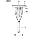
上記実施の形態や変形例では、集光レンズ62は長尺板状に形成されていたが、表示用LED67からの入射光を導光板42、142側に誘導しながら板厚(前後)方向に集光して導光板42、142に向けて光を出射することが可能であれば、例えば図22に示すように、表示用LED67として被覆可能なドーム形状の透光性部材からなる集光レンズを用いてもよい。   In the above-described embodiment and modification, the condensing lens 62 is formed in a long plate shape, but in the plate thickness (front-rear) direction while guiding the incident light from the display LED 67 to the light guide plates 42 and 142 side. If the light can be condensed and emitted toward the light guide plates 42 and 142, for example, as shown in FIG. 22, a condensing lens made of a dome-shaped translucent member that can be covered as the display LED 67 May be used.

この集光レンズには、表示用LEDを収納可能な凹部162aが形成され、その凹部162aの内面が入射面となっている。形状は、表示用LED67側から導光板側42に向けて先細りとなるドーム形状をなし、図22中の下端部から光を出射可能に構成されている。このような集光レンズ162にあっても、表示用LED67から導光板42に向けて前後幅寸法が漸次短寸となり、入射光を全反射により導光板42側に誘導しながら前後方向に集光させて出射させることができる。   The condensing lens is formed with a concave portion 162a capable of accommodating a display LED, and the inner surface of the concave portion 162a is an incident surface. The shape is a dome shape that tapers from the display LED 67 side toward the light guide plate side 42, and is configured such that light can be emitted from the lower end in FIG. Even in such a condensing lens 162, the front-rear width dimension gradually becomes shorter from the display LED 67 toward the light guide plate 42, and the incident light is condensed in the front-rear direction while being guided to the light guide plate 42 side by total reflection. Can be emitted.

上記実施の形態の集光レンズ62は、前面及び背面のそれぞれが平坦状の傾斜面に形成されていたが、内部に入射された光を導光板42、142側に誘導可能であれば、図22に示す集光レンズ162のような曲面に構成されてもいてもよい。   In the condensing lens 62 of the above embodiment, each of the front surface and the back surface is formed on a flat inclined surface. However, if the light incident on the condensing lens 62 can be guided to the light guide plates 42 and 142 side, it is 22 may be configured as a curved surface like a condensing lens 162 shown in FIG.

上記実施の形態の集光レンズ62の出射面は、正面視略半円形状に形成され、入射面が湾曲状に構成されていたが、例えば図23の変形例の集光レンズ262に示すように、凸部262aが台形状に形成されるなど種々に変更可能である。また、入射面も、必ずしも湾曲面に構成されていなくてもよい。   The exit surface of the condensing lens 62 in the above embodiment is formed in a substantially semicircular shape when viewed from the front, and the entrance surface is formed in a curved shape. For example, as shown in the condensing lens 262 of the modification of FIG. In addition, the projection 262a can be variously changed such as being formed in a trapezoidal shape. Further, the incident surface does not necessarily have to be a curved surface.

上記実施の形態及び変形例では、導光板42、142の発光部46は、導光板42、142の表面に形成される凹部で構成されていたが、導光板42、142の内部に入射された入射光を前面に出射させることで導光板42,142に表示情報を表示可能なものであれば、例えば図24に示すように、導光板42、142の内部に入射された入射光を全反射させずに、前面から出射させる複数の凸部等の透光誘導部であってもよいし、あるいは、前後面に形成される凹部や凸部ではなく、導光板42、142の内部に形成される反射部等であってもよい。   In the embodiment and the modification described above, the light emitting portion 46 of the light guide plates 42 and 142 is configured by the concave portion formed on the surface of the light guide plates 42 and 142, but is incident on the inside of the light guide plates 42 and 142. If the display information can be displayed on the light guide plates 42 and 142 by emitting the incident light to the front surface, for example, as shown in FIG. 24, the incident light incident on the light guide plates 42 and 142 is totally reflected. Instead, it may be a light transmission guiding portion such as a plurality of convex portions that are emitted from the front surface, or may be formed inside the light guide plates 42 and 142 instead of the concave portions and convex portions formed on the front and rear surfaces. It may be a reflective part or the like.

上記実施の形態では、表示ユニット40、40’には、光源としての表示用LED67と導光板42、142との間に、表示用LED67からの光を導光板42、142の板厚方向に集光して導光板42、142の側面に向けて出射する集光レンズ67が設けられたが、こうした集光レンズを備えなくてもよい。   In the above embodiment, the display units 40 and 40 ′ collect light from the display LED 67 in the thickness direction of the light guide plates 42 and 142 between the display LED 67 as a light source and the light guide plates 42 and 142. Although the condensing lens 67 which radiates | emits and radiate | emits toward the side surface of the light-guide plates 42 and 142 was provided, such a condensing lens does not need to be provided.

上記実施の形態では、表示ユニット40、40’の導光板42、142は、前導光板42A、142Aと後導光板42B、142Bとから構成されていたが、前後方向に重畳して配置した3枚以上の導光板から構成されてもよい。   In the above embodiment, the light guide plates 42 and 142 of the display units 40 and 40 ′ are composed of the front light guide plates 42A and 142A and the rear light guide plates 42B and 142B. You may comprise from the above light-guide plate.

上記実施の形態及び変形例では、前導光板42A、142Aと後導光板42B、142Bとが所定の隙間を隔てて離間配置されることで、後導光板142Bにて反射されて前側に出射された出射光により前側の導光板42、142の発光部で反射して光ることが防止されていたが、互いに当接して配置されていてもよい。   In the embodiment and the modification described above, the front light guide plates 42A and 142A and the rear light guide plates 42B and 142B are spaced apart from each other with a predetermined gap, and are reflected by the rear light guide plate 142B and emitted to the front side. Although the light emitted from the light-emitting portions of the front light guide plates 42 and 142 is prevented from being emitted by the emitted light, they may be disposed in contact with each other.

上記実施の形態及び変形例では、表示ユニット40には、導光板42、142の左端面と下端面とから光を入射可能に構成され、表示ユニット40’は、導光板の上端面から光を入射可能に構成されていたが、表示ユニット40の導光板42の一辺にのみ光源が設けられてもよいし、表示ユニット40’の導光板142の二辺に光源が設けられてもよい。また、光源から導光板42、142への光の出射は、上下側端面、左右側端面のいずれからなされてもよい。さらに光源は、LEDに限定されるものではなく、例えば冷陰極管等他の発光体を用いてもよい。   In the embodiment and the modification described above, the display unit 40 is configured to allow light to enter from the left end surface and the lower end surface of the light guide plates 42 and 142, and the display unit 40 ′ receives light from the upper end surface of the light guide plate. Although it is configured to be incident, a light source may be provided only on one side of the light guide plate 42 of the display unit 40, or a light source may be provided on two sides of the light guide plate 142 of the display unit 40 '. In addition, light may be emitted from the light source to the light guide plates 42 and 142 from either the upper or lower end face or the left or right end face. Furthermore, the light source is not limited to the LED, and other light emitters such as a cold cathode tube may be used.

上記実施の形態及び変形例では、表示ユニット40は、遊技盤2の画像表示装置5の前面に取り付けられるものとしたが、遊技盤2の画像表示装置5の前面以外の場所に取り付けられてもよいし、例えば遊技機用枠3の前面板が導光板42、142で形成されて、この導光板42に光が入射されるように表示ユニット40が構成されるなど、遊技用枠3に表示ユニット40が設けられてもよい。   In the above embodiment and modification, the display unit 40 is attached to the front surface of the image display device 5 of the game board 2, but it may be attached to a place other than the front surface of the image display device 5 of the game board 2. For example, the display unit 40 may be configured such that the front plate of the gaming machine frame 3 is formed by the light guide plates 42 and 142 and light is incident on the light guide plate 42. A unit 40 may be provided.

上記実施の形態及び変形例では、前導光板42A、142A及び後導光板42B、142Bは、透明板で構成されるものとしたが、光源からの光を反射して表示情報を表示できるように透光性を有するものであればよく、半透明や不透明であってもよい。また、着色されていてもよく、有色透明などであってもよい。   In the above-described embodiment and modification, the front light guide plates 42A and 142A and the rear light guide plates 42B and 142B are made of transparent plates. Any material having light properties may be used, and it may be translucent or opaque. Moreover, it may be colored and may be colored and transparent.

上記実施の形態では、遊技機として、パチンコ遊技機1に、本発明を適用して説明したが、例えば、スロットマシンやゲーム機などに上述の表示ユニット40、40’が搭載されるなど、他の遊技機に本発明を適用してもよい。   In the above-described embodiment, the present invention is applied to the pachinko gaming machine 1 as a gaming machine. However, for example, the display units 40 and 40 ′ described above are mounted on a slot machine or a gaming machine. The present invention may be applied to other gaming machines.

1 … パチンコ遊技機
2 … 遊技盤
3 … 遊技機用枠
4A、4B … 特別図柄表示装置
5 … 表示装置
6A … 普通入賞球装置
6B … 普通可変入賞球装置
7 … 特別可変入賞球装置
8L、8R … スピーカ
9 … 遊技効果ランプ
20 … 普通図柄表示器
21 … ゲートスイッチ
26 … 通過ゲート
40、40’ … 表示ユニット
42 … 導光板
42A … 前導光板
42B … 後導光板
46、46Aa、46Ab、46Ba、46Bb … 発光部
50 … フレーム体
52 … 上フレーム
54 … 左フレーム
56 … 下フレーム
60 … 光表示部
62 … 集光レンズ
66 … LED基板
67 … 表示用LED
142A、142B … 導光板
143A、143B … 差込部
504 … フレーム枠体
N、N1 … ネジ
DESCRIPTION OF SYMBOLS 1 ... Pachinko machine 2 ... Game board 3 ... Gaming machine frame 4A, 4B ... Special symbol display device 5 ... Display device 6A ... Ordinary winning ball device 6B ... Ordinary variable winning ball device 7 ... Special variable winning ball device 8L, 8R ... Speaker 9 ... Game effect lamp 20 ... Normal symbol display 21 ... Gate switch 26 ... Passing gate 40, 40 '... Display unit 42 ... Light guide plate 42A ... Front light guide plate 42B ... Rear light guide plates 46, 46Aa, 46Ab, 46Ba, 46Bb ... Light emitting part 50 ... Frame body 52 ... Upper frame 54 ... Left frame 56 ... Lower frame 60 ... Optical display part 62 ... Condensing lens 66 ... LED substrate 67 ... LED for display
142A, 142B ... Light guide plates 143A, 143B ... Insertion part 504 ... Frame frame N, N1 ... Screw

Claims (2)

遊技用価値を用いて遊技を行うことが可能な遊技機であって、
透光性を有し、遊技者が視認可能に配置された第1導光板と、
透光性を有し、遊技者が視認可能に配置された第2導光板と、
前記第1導光板と前記第2導光板とを対面させて保持する保持部材と、を備え、
前記第1導光板は、該第1導光板の側面から内部に入射される光源からの光により発光して該第1導光板に画像を表示させる第1発光部を有するとともに、光源からの光が入射される面から離れた位置に第1取付部が設けられ、
前記第2導光板は、該第2導光板の側面から内部に入射される光源からの光により発光して該第2導光板に前記第1導光板とは異なる画像を表示させる第2発光部を有するとともに、光源からの光が入射される面から離れ、かつ前記第1導光板の第1取付部とは異なる位置に第2取付部が設けられ、
前記保持部材には、前記第1導光板の第1取付部に対応する位置に第1固定部が設けられているとともに前記第2導光板の第2取付部に対応する位置に第2固定部が設けられており、該保持部材は、前記第1固定部と前記第1取付部とが第1の係合部材で係合されることにより前記第1導光板を保持するとともに、前記第2固定部と前記第2取付部とが第2の係合部材で係合されることにより前記第2導光板を保持し、
前記第1導光板及び前記第2導光板のうち、一方の導光板に画像を表示して行う演出と、両方の導光板に画像を表示して行う演出とを実行可能な演出実行手段と、
前記光源からの光が入射し、前記第1導光板あるいは前記第2導光板に向けて光を出射して発光させる集光部材と、を更に備え、
前記集光部材の光出射面は、前記第1導光板あるいは前記第2導光板に向けて凸状の湾曲面である、
ことを特徴とする遊技機。
A gaming machine capable of playing a game using gaming value,
A first light guide plate having translucency and disposed so as to be visible to a player;
A second light guide plate having translucency and disposed so as to be visible to the player;
A holding member that holds the first light guide plate and the second light guide plate facing each other,
The first light guide plate includes a first light emitting unit that emits light from a light source incident inside from a side surface of the first light guide plate and displays an image on the first light guide plate. A first mounting portion is provided at a position away from the surface on which the light is incident;
The second light guide plate emits light from a light source incident inside from a side surface of the second light guide plate, and causes the second light guide plate to display an image different from the first light guide plate. And a second mounting portion is provided at a position different from the first mounting portion of the first light guide plate, away from the surface on which light from the light source is incident,
The holding member is provided with a first fixing portion at a position corresponding to the first mounting portion of the first light guide plate and a second fixing portion at a position corresponding to the second mounting portion of the second light guide plate. The holding member holds the first light guide plate by engaging the first fixing portion and the first attachment portion with a first engaging member, and the second holding member. The fixed portion and the second attachment portion are engaged by the second engagement member to hold the second light guide plate,
An effect execution means capable of executing an effect of displaying an image on one of the first light guide plate and the second light guide plate and an effect of displaying an image on both light guide plates ;
And light incident from the light source, further example Bei and a condensing member to emit light to emit light toward the first light guide plate or the second light guide plate,
The light exit surface of the light collecting member is a curved surface that is convex toward the first light guide plate or the second light guide plate.
A gaming machine characterized by that.
遊技用価値を用いて遊技を行うことが可能な遊技機であって、
透光性を有し、遊技者が視認可能に配置された第1導光板と、
透光性を有し、遊技者が視認可能に配置された第2導光板と、
前記第1導光板と前記第2導光板とを対面させて保持する保持部材と、を備え、
前記第1導光板は、該第1導光板の側面から内部に入射される光源からの光により発光して該第1導光板の板面に画像を表示させる第1発光部を有するとともに、光源からの光が入射される面から離れた位置に第1被当接部が設けられ、
前記第2導光板は、該第2導光板の側面から内部に入射される光源からの光により発光して該第2導光板の板面に前記第1導光板とは異なる画像を表示させる第2発光部を有するとともに、光源からの光が入射される面から離れ、かつ前記第1導光板の第1被当接部とは異なる形状の第2被当接部が設けられ、
前記保持部材には、前記第1導光板を保持するときに該第1導光板の第1被当接部に当接する第1当接部が設けられているとともに、前記第2導光板を保持するときに該第2導光板の第2被当接部に当接する第2当接部が設けられ、
前記第1導光板及び前記第2導光板のうち、一方の導光板の板面に画像を表示して行う演出と、両方の導光板の板面に画像を表示して行う演出とを実行可能な演出実行手段と、
前記光源からの光が入射し、前記第1導光板あるいは前記第2導光板に向けて光を出射して発光させる集光部材と、を更に備え、
前記集光部材の光出射面は、前記第1導光板あるいは前記第2導光板に向けて凸状の湾曲面である、
ことを特徴とする遊技機。
A gaming machine capable of playing a game using gaming value,
A first light guide plate having translucency and disposed so as to be visible to a player;
A second light guide plate having translucency and disposed so as to be visible to the player;
A holding member that holds the first light guide plate and the second light guide plate facing each other,
The first light guide plate includes a first light emitting unit that emits light from a light source incident inside from a side surface of the first light guide plate and displays an image on the plate surface of the first light guide plate. A first contacted portion is provided at a position away from the surface on which the light from is incident,
The second light guide plate emits light from a light source incident inside from a side surface of the second light guide plate, and displays a different image from the first light guide plate on the plate surface of the second light guide plate. A second abutting portion having a shape different from the first abutting portion of the first light guide plate, and having a light emitting portion, and being away from a surface on which light from the light source is incident;
The holding member is provided with a first contact portion that contacts the first contacted portion of the first light guide plate when holding the first light guide plate, and holds the second light guide plate. A second abutting portion that abuts on the second abutted portion of the second light guide plate when
An effect of displaying an image on the plate surface of one of the first light guide plate and the second light guide plate and an effect of displaying an image on the plate surfaces of both light guide plates can be executed. Directing execution means ,
And light incident from the light source, further example Bei and a condensing member to emit light to emit light toward the first light guide plate or the second light guide plate,
The light exit surface of the light collecting member is a curved surface that is convex toward the first light guide plate or the second light guide plate.
A gaming machine characterized by that.
JP2016051157A 2016-03-15 2016-03-15 Game machine Expired - Fee Related JP6124483B2 (en)

Priority Applications (1)

Application Number Priority Date Filing Date Title
JP2016051157A JP6124483B2 (en) 2016-03-15 2016-03-15 Game machine

Applications Claiming Priority (1)

Application Number Priority Date Filing Date Title
JP2016051157A JP6124483B2 (en) 2016-03-15 2016-03-15 Game machine

Related Parent Applications (1)

Application Number Title Priority Date Filing Date
JP2012197597A Division JP5926657B2 (en) 2012-09-07 2012-09-07 Game machine

Publications (3)

Publication Number Publication Date
JP2016105901A JP2016105901A (en) 2016-06-16
JP2016105901A5 JP2016105901A5 (en) 2016-09-23
JP6124483B2 true JP6124483B2 (en) 2017-05-10

Family

ID=56120259

Family Applications (1)

Application Number Title Priority Date Filing Date
JP2016051157A Expired - Fee Related JP6124483B2 (en) 2016-03-15 2016-03-15 Game machine

Country Status (1)

Country Link
JP (1) JP6124483B2 (en)

Families Citing this family (3)

* Cited by examiner, † Cited by third party
Publication number Priority date Publication date Assignee Title
JP6777484B2 (en) * 2016-09-23 2020-10-28 株式会社三共 Game machine
JP6939232B2 (en) * 2017-08-10 2021-09-22 オムロン株式会社 Pachinko machine
JP7466203B2 (en) 2021-05-31 2024-04-12 株式会社サンセイアールアンドディ Gaming Machines

Family Cites Families (3)

* Cited by examiner, † Cited by third party
Publication number Priority date Publication date Assignee Title
JP4839643B2 (en) * 2005-03-15 2011-12-21 株式会社三洋物産 Game machine
JP2012165799A (en) * 2011-02-10 2012-09-06 Daiichi Shokai Co Ltd Pachinko game machine
JP5926657B2 (en) * 2012-09-07 2016-05-25 株式会社三共 Game machine

Also Published As

Publication number Publication date
JP2016105901A (en) 2016-06-16

Similar Documents

Publication Publication Date Title
JP5926657B2 (en) Game machine
JP2019017883A (en) Game machine
JP6124483B2 (en) Game machine
JP2015076308A (en) Game machine
JP2011087686A (en) Light-emitting unit
JP6769938B2 (en) Game machine
JP4803585B2 (en) Electrical equipment for bullet ball machines
JP2019141214A (en) Game machine
JP2007267891A (en) Illumination device for game machine
JP2007267892A (en) Illumination device for game machine
JP2005185471A (en) Game machine
JP6569787B2 (en) Game machine
JP2019129948A (en) Game machine
JP6340676B2 (en) Game machine
JP5476426B2 (en) Game machine
WO2021059556A1 (en) Display device and game device
JP5667155B2 (en) Game machine
JP7074496B2 (en) Pachinko machine
JP6953283B2 (en) Pachinko machine
JP7041533B2 (en) Pachinko machine
JP6614267B2 (en) Game machine
JP6649322B2 (en) Gaming machine
JP2009082340A (en) Game machine
JP2006320765A (en) Pinball game machine
JP6319479B2 (en) Game machine

Legal Events

Date Code Title Description
A621 Written request for application examination

Free format text: JAPANESE INTERMEDIATE CODE: A621

Effective date: 20160315

A521 Request for written amendment filed

Free format text: JAPANESE INTERMEDIATE CODE: A523

Effective date: 20160804

A131 Notification of reasons for refusal

Free format text: JAPANESE INTERMEDIATE CODE: A132

Effective date: 20161213

A521 Request for written amendment filed

Free format text: JAPANESE INTERMEDIATE CODE: A523

Effective date: 20170210

TRDD Decision of grant or rejection written
A01 Written decision to grant a patent or to grant a registration (utility model)

Free format text: JAPANESE INTERMEDIATE CODE: A01

Effective date: 20170314

A61 First payment of annual fees (during grant procedure)

Free format text: JAPANESE INTERMEDIATE CODE: A61

Effective date: 20170403

R150 Certificate of patent or registration of utility model

Ref document number: 6124483

Country of ref document: JP

Free format text: JAPANESE INTERMEDIATE CODE: R150

R250 Receipt of annual fees

Free format text: JAPANESE INTERMEDIATE CODE: R250

R250 Receipt of annual fees

Free format text: JAPANESE INTERMEDIATE CODE: R250

LAPS Cancellation because of no payment of annual fees