JP6124017B2 - Sash upper frame - Google Patents
Sash upper frame Download PDFInfo
- Publication number
- JP6124017B2 JP6124017B2 JP2014073387A JP2014073387A JP6124017B2 JP 6124017 B2 JP6124017 B2 JP 6124017B2 JP 2014073387 A JP2014073387 A JP 2014073387A JP 2014073387 A JP2014073387 A JP 2014073387A JP 6124017 B2 JP6124017 B2 JP 6124017B2
- Authority
- JP
- Japan
- Prior art keywords
- sash
- indoor
- outdoor
- shoji
- partition
- Prior art date
- Legal status (The legal status is an assumption and is not a legal conclusion. Google has not performed a legal analysis and makes no representation as to the accuracy of the status listed.)
- Active
Links
Images


Classifications
-
- E—FIXED CONSTRUCTIONS
- E06—DOORS, WINDOWS, SHUTTERS, OR ROLLER BLINDS IN GENERAL; LADDERS
- E06B—FIXED OR MOVABLE CLOSURES FOR OPENINGS IN BUILDINGS, VEHICLES, FENCES OR LIKE ENCLOSURES IN GENERAL, e.g. DOORS, WINDOWS, BLINDS, GATES
- E06B3/00—Window sashes, door leaves, or like elements for closing wall or like openings; Layout of fixed or moving closures, e.g. windows in wall or like openings; Features of rigidly-mounted outer frames relating to the mounting of wing frames
- E06B3/32—Arrangements of wings characterised by the manner of movement; Arrangements of movable wings in openings; Features of wings or frames relating solely to the manner of movement of the wing
- E06B3/34—Arrangements of wings characterised by the manner of movement; Arrangements of movable wings in openings; Features of wings or frames relating solely to the manner of movement of the wing with only one kind of movement
- E06B3/42—Sliding wings; Details of frames with respect to guiding
- E06B3/46—Horizontally-sliding wings
- E06B3/4609—Horizontally-sliding wings for windows
Description
本発明は、サッシ上枠に関する。 The present invention relates to a sash upper frame.
従来、サッシ枠およびサッシ障子の框に、アルミニウムなどの金属と樹脂とを用いた複合サッシが知られている(例えば、特許文献1参照)。このような複合サッシを用いることで、断熱性能を高めることができるとともに、室内側の意匠性を高めることができる。
通常、引違窓の複合サッシには、サッシ枠の上下に、それぞれ開口部の内側に向かって突出し、室外側のサッシ障子の開閉移動をガイドする室外側レールおよび室内側のサッシ障子の開閉移動をガイドする室内側レールが設けられていて、これらの室外側レールおよび室内側レールとの間に樹脂カバーが設けられている。
Conventionally, a composite sash is known in which a metal such as aluminum and a resin are used for a sash frame and a sash shoji (see, for example, Patent Document 1). By using such a composite sash, the heat insulation performance can be enhanced and the design of the indoor side can be enhanced.
Normally, a sliding window composite sash has an outdoor rail that projects toward the inside of the opening at the top and bottom of the sash frame and guides the opening and closing movement of the outdoor sash door and the opening and closing movement of the indoor sash door. An indoor rail for guiding is provided, and a resin cover is provided between the outdoor rail and the indoor rail.
ところで、引違窓は、サッシ障子の上框および下框に形成された溝部にサッシ枠の室外側レールまたは室内側レールが嵌めこまれる構造であるため、サッシ枠にサッシ障子を建て込む際に、けんどん式に建て込まれている。このため、サッシ障子とサッシ上枠との間には、建て込み代となる下方に開口された空部が必要となっている。
このため、室外側レールと室内側レールの間に樹脂カバーが設けられている複合サッシであっても、室外の冷温によってサッシ障子とサッシ上枠との間の空部の空気が冷却され、室内の温度が低下したり、室内において結露が生じたりする虞がある。
これに対し、この空部に断熱材や空気層などの断熱機構を設けることが望まれるが、この空部がサッシ障子を建て込む際の建て込み代となるため、断熱機構を設けることができない、または、この空部に断熱機構を設けるためには、空部を大きくする必要があり、サッシ枠を大きくしなければならないという問題がある。
By the way, the sliding window is a structure in which the outdoor rail or the indoor rail of the sash frame is fitted into the grooves formed in the upper and lower ridges of the sash shoji, so when installing the sash shoji into the sash frame, It is built in a kendo style. For this reason, a vacant part opened downward is required between the sash shoji and the sash upper frame.
For this reason, even in a composite sash in which a resin cover is provided between the outdoor rail and the indoor rail, the air in the empty space between the sash shoji and the sash upper frame is cooled by the outdoor cold temperature, There is a risk that the temperature of the battery may decrease or condensation may occur in the room.
On the other hand, it is desirable to provide a heat insulating mechanism such as a heat insulating material or an air layer in this empty portion, but since this empty portion is an installation allowance when a sash shoji is installed, it is not possible to provide a heat insulating mechanism. Alternatively, in order to provide a heat insulating mechanism in the empty portion, there is a problem that the empty portion needs to be enlarged and the sash frame must be enlarged.
そこで、本発明は、室内外の断熱ができ、室内の結露を防止できるとともに、サッシ枠にサッシ障子をけんどん式に建て込むことができるサッシ上枠を提供することを目的とする。 Therefore, an object of the present invention is to provide a sash upper frame that can insulate indoors and outdoors, prevent dew condensation in the room, and can sash sash shojis in a sash frame.
上記目的を達成するため、本発明に係るサッシ上枠は、室外側サッシ障子および室内側サッシ障子をスライド可能に支持するサッシ枠のサッシ上枠において、躯体に固定された本体部と、該本体部から下方に突出し、前記室外側サッシ障子のスライド移動をガイドする室外側レールと、前記本体部から下方に突出し、前記室内側サッシ障子のスライド移動をガイドする室内側レールと、前記室外側レールと前記室内側レールとの間に配置され、前記本体部の少なくとも一部を覆い、内部空間を形成するように区画された区画部と、を備え、前記区画部は、上下方向に移動可能または弾性変形可能に構成されているとともに、前記サッシ枠に支持された前記室外側サッシ障子および前記室内側サッシ障子と上下方向に離間していることを特徴とする。 In order to achieve the above object, a sash upper frame according to the present invention includes a main body portion fixed to a housing in a sash upper frame of a sash frame that slidably supports an outdoor sash shoji and an indoor sash shoji, and the main body. An outdoor rail that protrudes downward from a section and guides the sliding movement of the outdoor sash shoji, an indoor rail that protrudes downward from the main body and guides the sliding movement of the indoor sash shoji, and the outdoor rail And a partition part that is disposed between the indoor side rail and covers at least a part of the main body part and forms an internal space, and the partition part is movable in the vertical direction or It is configured to be elastically deformable, and is vertically spaced from the outdoor sash shoji supported by the sash frame and the indoor sash shoji. That.
本発明では、本体部、室外側レールおよび室内側レールの間の空部が区画部によって区画されることにより、区画部によって区画された空間が断熱空気層となってその上側と下側とを断熱できるため、室内外の断熱ができて、室内側の結露を防止できる。
そして、区画部は、上下方向に移動可能または弾性変形可能に構成されていることにより、サッシ枠にサッシ障子をけんどん式に建て込む際に、上側に移動する室外側サッシ障子および室内側サッシ障子と区画部とが干渉しても、区画部が上側に移動したり、弾性変形したりするため、室外側サッシ障子および室内側サッシ障子の上側への移動が阻止されずスムーズに室外側サッシ障子および室内側サッシ障子をサッシ枠に建て込むことができる。また、室外側サッシ障子および室内側サッシ障子が建て込まれた後は、区画部が重力によって下側に移動したり、弾性変形が復元されたりするため、区画部によって区画された空間を確実に確保することができる。
In the present invention, the main body portion, by an empty portion between the outdoor side rails and the indoor side rails are partitioned by the partition portion, the upper and lower Accordingly compartmented space partition portion becomes a heat insulating air layer Since the inside can be insulated, indoor and outdoor insulation can be achieved, and condensation on the indoor side can be prevented.
The partition portion is configured to be movable in the vertical direction or to be elastically deformable, so that when the sash shoji is built into the sash frame in an ergonomic manner, the outdoor sash shoji and the indoor sash are moved upward. Even if the shoji and the compartment part interfere, the compartment part moves upward or elastically deforms. Therefore, the outdoor sash shoji and the indoor sash shoji are not prevented from moving upward, and the outdoor sash is smoothly moved. Shoji and indoor sash shoji can be built in the sash frame. In addition, after the outdoor sash shoji and the indoor sash shoji are installed, the partition part moves downward due to gravity and elastic deformation is restored, so that the space partitioned by the partition part is surely secured. Can be secured.
また、本発明に係るサッシ上枠では、前記本体部に係止され前記区画部を支持する支持部を備え、該支持部は、硬質樹脂で形成され、前記区画部は、軟質樹脂で形成されている構成としてもよい。
このような構成とすることにより、区画部が軟質樹脂で形成されていて弾性変形可能であったとしても、支持部は、硬質樹脂で形成されていて容易に変形しないため、本体部への取付を容易に行うことができる。また、支持部を介して区画部が本体部へ固定されるため、区画部が本体部から外れることを防止できる。
The sash upper frame according to the present invention includes a support portion that is locked to the main body portion and supports the partition portion. The support portion is formed of a hard resin, and the partition portion is formed of a soft resin. It is good also as composition which has.
By adopting such a configuration, even if the partition part is formed of a soft resin and can be elastically deformed, the support part is formed of a hard resin and does not easily deform. Can be easily performed. Moreover, since a partition part is fixed to a main-body part via a support part, it can prevent that a partition part remove | deviates from a main-body part.
また、本発明に係るサッシ上枠では、前記区画部は、上下方向に移動可能に構成され、上側に移動した前記区画部を下側に押し戻す区画部位置戻し材を備える構成としてもよい。
このような構成とすることにより、区画部が上側に移動した際に、重力だけでなく区画部位置戻し材に下側に押し戻されることによって、区画部を確実に元の位置および元の形状に戻すことができ、断熱空気層を確実に確保することができる。
Moreover, in the sash upper frame which concerns on this invention, the said division part is comprised so that a vertical movement is possible, It is good also as a structure provided with the division part position return material which pushes back the said division part which moved to the upper side.
By adopting such a configuration, when the partition portion moves upward, not only gravity but also the partition portion position return material is pushed back downward to ensure that the partition portion is in the original position and shape. It can return, and a heat insulation air layer can be ensured reliably.
また、本発明に係るサッシ上枠では、前記区画部は、前記内部空間を複数に区画することが好ましい。
このような構成とすることにより、断熱空気層が区分されていない場合と比べて、断熱空気層内の熱の移動を抑制することができ、断熱空気層の断熱性能を向上させることができる。
また、本発明に係るサッシ上枠では、前記区画部は、前記室外側サッシ障子および前記室内側サッシ障子が閉鎖した状態における前記室外側サッシ障子側の縦枠と、前記室内側サッシ障子の召合框との間の領域のみに設けられていてもよい。
Moreover, in the sash upper frame which concerns on this invention, it is preferable that the said partition part partitions the said internal space into plurality .
By setting it as such a structure, compared with the case where the heat insulation air layer is not divided, the heat transfer in a heat insulation air layer can be suppressed and the heat insulation performance of a heat insulation air layer can be improved.
Further, in the sash upper frame according to the present invention, the partition portion includes a vertical frame on the outdoor sash shoji side in a state where the outdoor sash shoji and the indoor sash shoji are closed, and a sum of the indoor sash shoji. It may be provided only in the area between the joints.
本発明によれば、室外側レールと室内側レールとの間の空部が区画部によって上下に区画され、区画部と本体部との間に断熱空気層が形成されていることにより、断熱空気層がその上側と下側とを断熱できるため、室内外の断熱ができて、室内側の結露を防止できる。 According to the present invention, the space between the outdoor-side rail and the indoor-side rail is partitioned vertically by the partition, and the heat-insulating air layer is formed between the partition and the main body. Since the layer can insulate the upper side and the lower side, it is possible to insulate indoors and outdoors, and to prevent condensation on the indoor side.
(第1実施形態)
以下、本発明の第1実施形態によるサッシ上枠について、図1乃至図4に基づいて説明する。
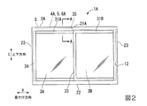
図1および図2に示すように、第1実施形態によるサッシ1Aは、引違窓のアルミニウムと樹脂の複合のサッシで、建物11の開口部12に固定されたサッシ枠2Aと、サッシ枠2Aの内部に見付け方向にスライド可能に設置される室外側サッシ障子3Aおよび室内側サッシ障子3Bと、を備えている。
(First embodiment)
Hereinafter, the sash upper frame by 1st Embodiment of this invention is demonstrated based on FIG. 1 thru | or FIG.
As shown in FIGS. 1 and 2, the
図2に示すように、サッシ枠2Aは、開口部12の縁部に沿った矩形状に形成されていて、見付け方向に延在するサッシ上枠21Aおよびサッシ下枠22と、上下方向に延在する一対のサッシ縦枠23,23と、を有している。
ここで、サッシ上枠21A以外は、公知のものとして以下説明する。
As shown in FIG. 2, the
Here, the parts other than the sash
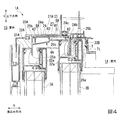
図3に示すように、サッシ上枠21Aは、建物11(図1参照)に固定された本体部24と、室外側サッシ障子3Aのスライド移動をガイドする室外側レール25Aと、室内側サッシ障子3Bのスライド移動をガイドする室内側レール26Aと、室外側レール25Aと室内側レール26Aとの間の空部27を上下方向に区画する区画部4Aと、本体部24に係止され区画部4Aを支持する支持部5と、を備えている。また、本体部24と区画部4Aとの間には、断熱空気層6Aが形成されている。
As shown in FIG. 3, the sash
本体部24は、それぞれ見付け方向に延在し、室外13側に配される室外側形材24aと、室内14側に配される室内側形材24bと室外側形材24aと室内側形材24bとの間に設けられて室外側形材24aと室内側形材24bとを連結する断熱ブリッジ材24cと、を有している。
室外側形材24aおよび室内側形材24bは、アルミニウムを材料として形成され、断熱ブリッジ材24cは、室外側形材24aおよび室内側形材24bを形成する材料よりも熱伝導率の低い樹脂やウレタンを材料として形成されている。
The
The
室外側レール25Aは、見付け方向に延在し室外側形材24aの下面から下方に突出する板状の部材で構成されている。また、室内側レール26Aは、見付け方向に延在し室内側形材24bの下面から下方に突出する板状の部材で構成されている。
これらの室外側レール25Aと室内側レール26Aとは、見込み方向に所定の間隔をあけて設けられていて、この間隔が下方に開口された空部27を構成している。
室外側レール25Aおよび室内側レール26Aは、アルミニウムを材料として形成されている。
The
The
The
また、本実施形態では、本体部24の室内側形材24bの下側および室内側レール26Aの室内14側の面に沿って樹脂カバー7が設けられていて、樹脂カバー7のうち室内側レール26Aの室内14側の面に沿っている部分71が、室内側レール26Aに係止されている。ここで、以下では、上述したアルミニウムを材料として形成された室内側レール26Aと、樹脂カバー7のうち室内側レール26Aの室内14側の面に沿っている部分71と、を室内側レール26Aとして説明する。
In the present embodiment, the
室外側レール25Aは、室外側サッシ障子3Aの上框31Aに形成された上方に開口し見付け方向に延びる溝部32Aに挿入可能に構成され、室内側レール26Aは、室内側サッシ障子3Bの上框31Bに形成された上方に開口し見付け方向に延びる溝部32Bに挿入可能に構成されている。
そして、室外側サッシ障子3Aおよび室内側サッシ障子3Bがサッシ枠2Aに建て込まれると、室外側レール25Aは、下端部(先端部)25aが室外側サッシ障子3Aの溝部32Aの底部32aと上下方向に離間した状態で下端部25a側が溝部32Aに挿入され、室内側レール26Aは、下端部(先端部)26aが室内側サッシ障子3Bの溝部32Bの底部32aと上下方向に離間した状態で下端部26a側が溝部32Bに挿入されている。このとき、室外側サッシ障子3Aおよび室内側サッシ障子3Bのそれぞれの上框31A,31Bの上端部は、サッシ上枠21Aの本体部24と上下方向に離間している。
The
When the
また、室外側レール25Aおよび室内側レール26Aには、上端部(基端部)25b,26b近傍に他方のレール側に向かって突出する突出片25c,26cがそれぞれ形成されていて、突出片25c,26cと本体部24の間には隙間が形成されている。
The
空部27は、見付け方向に延在し、本体部24の下側を向く面と、室外側レール25Aの室内14側の面と、室内側レール26Aの室外13側の面とに囲まれて、見込み方向の断面形状が下方に開口する略矩形状に形成されている。
この空部27のうち、室外側サッシ障子3Aおよび室内側サッシ障子3Bが開口部12を閉鎖した状態における、室外側サッシ障子3A側の縦枠23と、室内側サッシ障子3Bの召合框33との間の領域S(図2参照および図1の斜線部S1の上方の領域)に、区画部4A、支持部5および断熱空気層6Aが設けられている。ここで、以下ではこの領域Sを空部27として説明する。
The
Among the
支持部5は、平面視において空部27の略全体と重なり、その面が上下方向を向く長尺の板材で、硬質の塩ビなどの樹脂を材料として形成されている。
支持部5は、室外13側および室内14側の縁部が、室外側レール25Aおよび室内側レール26Aに形成された突出片25c,26cと本体部24との間の隙間にそれぞれ挿入されると、本体部24に係止されるように構成されている。
The support portion 5 is a long plate material that overlaps substantially the entire
When the support 5 is inserted into the gaps between the projecting
区画部4Aは、平面視において空部27の略全体と重なりその面が上下方向を向く長尺の板材で、支持部5の下側に支持部5と間隔をあけて設けられた水平板部41と、その面が略見込み方向を向く長尺の板材で、支持部5と水平板部41との間に設けられて支持部5と水平板部41とを連結する複数の連結部42と、を有している。
水平板部41と連結部42とは、弾性変形可能な塩ビなどの軟質樹脂を材料として一体に形成されている。
The
The horizontal
水平板部41は、室外側レール25Aおよび室内側レール26Aの高さ方向の中間部の高さに配されていて、下面41aが室外側サッシ障子3Aおよび室内側サッシ障子3Bの上框31A,31Bとそれぞれ離間するように構成されている。
また、水平板部41には、見込み方向の中間部で、平面視において室内側サッシ障子3Bの上框31Bの室外13側の端部よりも室外13側に、見付け方向全体にわたって段部41cが形成されていて、下面41aのうち室内14側が室外13側よりも高い位置となるように構成されている。
The
Further, the
ここで、図1に示すように、室外側サッシ障子3Aは、開口部12を閉鎖している状態および開放している状態のいずれにおいても、少なくとも戸先框34が区画部4Aの下側に配されているように構成されている。これに対し、室内側サッシ障子3Bは、開口部12を開放している状態では、区画部4Aの下側に配されているが、開口部12を閉鎖している状態では、区画部4Aと上下方向に重ならないように構成されている。
このため、室内側サッシ障子3Bが開口部12を開放している状態から閉鎖する見付け方向へスライド移動する際に、室内側サッシ障子3Bが上下方向に振れてしまうと、室内側サッシ障子3Bの上框31Bと召合框33とが連結する角部35(図2参照)が、水平板部41の端部を引っ掛けてしまう虞がある。
そこで、水平板部41には、段部41cが形成されていて、室内14側が室外13側よりも高い位置となるように構成されていることにより、室内側サッシ障子3Bの上框31Bと召合框33とが連結する角部35が、水平板部41の端部を引っ掛けることを防止できる。
Here, as shown in FIG. 1, the
For this reason, if the
Therefore, the
図3に戻り、連結部42は、見込み方向に間隔をあけて3つ設けられていて、区画部4Aの見込み方向の両端部近傍および中間部と、支持部5の見込み方向の両端部近傍および中間部とをそれぞれ連結している。
そして、見込み方向の両側の連結部42A,42A、水平板部41および支持部5に囲まれた空間が断熱空気層6Aを構成している。
また、見込み方向の中間部に設けられた連結部42Bによって断熱空気層6Aが2つに区分されている。
Returning to FIG. 3, three
The space surrounded by the connecting
Moreover, the heat
次に、第1実施形態によるサッシ枠2Aへ室外側サッシ障子3Aおよび室内側サッシ障子3Bを建て込む際のサッシ上枠21Aの空部27内の状態について説明する。
室外側サッシ障子3Aおよび室内側サッシ障子3Bは、サッシ枠2Aに対してけんどん式に建て込むように構成されている。
Next, the state in the
The outdoor-
例えば、室内側サッシ障子3Bをサッシ枠2Aに建て込む場合は、室内側サッシ障子3Bを斜めにして室外13側または室内14側からサッシ枠2Aに近づけ、室内側サッシ障子3Bの上框31Bの溝部32Bに室内側レール26Aの下端部26aを挿入させる。
そして、室内側サッシ障子3Bをガラス面が鉛直となるように向きを変えるとともに、室内側レール26Aの下端部26aが溝部32Bの奥まで挿入するように上側に移動させる。また、室内側サッシ障子3Bの下框32の溝部(不図示)が、サッシ枠2Aのサッシ下枠22(図2参照)の室内側レール(不図示)の上側に配されるように向きを調整する。
そして、室内側サッシ障子3Bを下側に移動させて、室内側サッシ障子3Bの下框32の溝部とサッシ枠2Aのサッシ下枠22の室内側レールとを嵌合させる。このようにしてサッシ枠2Aに室内側サッシ障子3Bが建て込まれる。
For example, when the
Then, the direction of the
Then, the
このとき、上側に移動した室内側サッシ障子3Bは、上框31Bが区画部4Aの水平板部41と当接するが、区画部4Aの水平板部41および連結部42は、弾性変形可能に構成されているため、図4に示すように、室内側サッシ障子3Bの上側への移動に追従して弾性変形する。このとき、断熱空気層6Aは、その形状が区画部4Aの弾性変形によって変形する。
そして、この状態から、図3に示すように、室内側サッシ障子3Bが下側に移動すると、変形した区画部4Aの水平板部41および連結部42は、その形状が復元される。
なお、室外側サッシ障子3Aについても、室内側サッシ障子3Bと同様にサッシ枠2Aに建て込むことができる。
At this time, in the
From this state, as shown in FIG. 3, when the
The
次に、上述した第1実施形態によるサッシ上枠21Aの作用・効果について図面を用いて説明する。
第1実施形態によるサッシ上枠21Aによれば、室外側レール25Aと室内側レール26Aとの間の空部27に断熱空気層6Aが形成されていることにより、断熱空気層6Aによって室内外を効率よく断熱できて、室内14の結露を防止できる。
また、区画部4Aは、弾性変形可能に構成されていることにより、サッシ枠2Aに室外側サッシ障子3Aおよび室内側サッシ障子3Bをけんどん式に建て込む際に、上側に移動する室外側サッシ障子3Aおよび室内側サッシ障子3Bが干渉しても、弾性変形することで室外側サッシ障子3Aおよび室内側サッシ障子3Bの上側への移動を阻止せず、スムーズに室外側サッシ障子3Aおよび室内側サッシ障子3Bをサッシ枠2Aに建て込むことができる。
また、室外側サッシ障子3Aおよび室内側サッシ障子3Bがサッシ枠2Aに建て込まれた後は、区画部4Aの弾性変形が復元されるため、断熱空気層6Aを確実に確保することができる。
Next, operations and effects of the sash
According to the sash
Further, the
Moreover, after the
また、本発明に係るサッシ上枠21Aでは、区画部4Aが本体部24に係止された支持部5に支持されるため、区画部4Aが本体部24から外れることを防止できる。
また、支持部5は、硬質樹脂で形成されていることにより、支持部5は、容易に変形せず、本体部24へ取り付けやすい構造となる。
また、断熱空気層6Aは、連結部42Bによって区分されていることにより、断熱空気層6Aの内部が区分されていない場合と比べて、断熱空気層6A内の熱の移動を抑制することができ、断熱性能を向上させることができる。
Further, in the sash
Further, since the support portion 5 is formed of a hard resin, the support portion 5 is not easily deformed and has a structure that can be easily attached to the
Moreover, the heat
また、水平板部41には、段部41cが形成されていて、室内14側が室外13側よりも高い位置となるように構成されていることにより、室内側サッシ障子3Bの上框31Bと召合框33とが連結する角部35が、水平板部41の端部を引っ掛けることを防止できるとともに、水平板部41に段部41cがなく室内14側の高さに合せて平坦な場合と比べて、断熱空気層6Aを大きく形成することができて、断熱性能を向上させることができる。
Further, the
次に、他実施形態について、添付図面に基づいて説明するが、上述の実施形態と同一又は同様な部材、部分には同一の符号を用いて説明を省略し、上述の実施形態と異なる構成について説明する。 Next, other embodiments will be described with reference to the accompanying drawings, but the same or similar members and parts as those of the above-described embodiment will be denoted by the same reference numerals, and description thereof will be omitted. explain.
(第2実施形態)
図5に示すように、第2実施形態によるサッシ1Bのサッシ上枠21Bは、室外側レール25Bと室内側レール26Bとの間の空部27に、第1実施形態のように支持部5が設けられていないとともに、第1実施形態による区画部4Aとは異なる区画部4Bが設けられている。
第2実施形態による区画部4Bは、見付け方向に延在しその面が略鉛直方向を向く長尺の板状で上下方向に間隔をあけて配された一対の水平板部43,43と、一対の水平板部43,43の見込み方向の両端部からそれぞれ下方に突出し見付け方向に延在しその面が略見込み方向を向く長尺の板状の一対の鉛直板部44,44と、を有している。
(Second Embodiment)
As shown in FIG. 5, the sash
The
一対の水平板部43,43は、平面視において空部27と略重なる大きさにそれぞれ形成されている。一対の水平板部43,43の間の空間45は、一対の鉛直板部44,44に挟まれている。
一対の鉛直板部44,44は、一方が室外側レール25Bの室内14側の面近傍に配置され、他方が室内側レール26Bの室外13側の面近傍に配置されている。
このような一対の鉛直板部44,44および一対の水平板部43,43を有する区画部4Bは、断面形状が略C字状となるように形成されている。
また、これらの一対の鉛直板部44,44および一対の水平板部43,43は、硬質樹脂などを材料として一体に形成されている。
The pair of
One of the pair of
The
Further, the pair of
ここで、第2実施形態では、室外側レール25Bおよび室内側レール26Bには、それぞれ下端部25a,26a近傍に上側から鉛直板部44,44の下端部側を挿入可能な溝部25d,26dが形成されている。
そして、鉛直板部44,44が室外側レール25Bおよび室内側レール26Bの溝部25d,26dに挿入された区画部4Bは、上下方向に移動可能に構成されている。
Here, in the second embodiment, the
And the
また、室外側レール25Bおよび室内側レール26Bは溝部25d,26dに区画部4Bの鉛直板部44,44がそれぞれ挿入された状態で、室外側サッシ障子3Aおよび室内側サッシ障子3Bの上框31A,31Bの溝部32A,32Bに挿入可能に構成されている。
そして、室外側レール25Bおよび室内側レール26Bの溝部25d,26dに区画部4Bの鉛直板部44,44がそれぞれ挿入され、室外側サッシ障子3Aおよび室内側サッシ障子3Bの上框31A,31Bの溝部32A,32Bに挿入された状態で、室外側サッシ障子3Aおよび室内側サッシ障子3Bがサッシ枠2Bに建て込まれると、区画部4Bの上側の水平板部43と本体部24との間に、断熱空気層6Bが形成されている。
The
Then, the
次に、第2実施形態によるサッシ枠2Bに室外側サッシ障子3Aおよび室内側サッシ障子3Bを建て込む際のサッシ上枠21Bの空部27内の状態について説明する。
なお、第2実施形態においても、第1実施形態と同様に室外側サッシ障子3Aおよび室内側サッシ障子3Bは、サッシ枠2Bに対してけんどん式に建て込むように構成されている。
そして、上側に移動した室内側サッシ障子3Bは、上框31Bが区画部4Bと当接するが、区画部4Bは、上下方向に移動可能に構成されているため、図6に示すように、室内側サッシ障子3Bに下側から押されて上側に移動する。このとき、断熱空気層6Bは、その形状が区画部4Bの移動によって変形する。なお、本実施形態では、区画部4Bが本体部24と当接するため、断熱空気層4Bがなくなるように構成されている。
そして、この状態から、図5に示すように、室内側サッシ障子3Bが下側に移動すると、上側に移動した区画部4Bは、重力によって下側に移動する。
なお、室外側サッシ障子3Aについても、室内側サッシ障子3Bと同様である。
Next, the state in the
In the second embodiment as well, the
In the
From this state, as shown in FIG. 5, when the
The
第2実施形態によるサッシ上枠21Bによれば、区画部4Bは、上下方向に移動可能に構成されて、室外側サッシ障子3Aおよび室内側サッシ障子3Bの上下移動に追従できることにより、第1実施形態と同様の効果を奏する。
また、一対の水平板部43,43の間の空間45においても、その上側と下側とを断熱することができるため、室内外の断熱性能を向上させることができる。
According to the sash
Also, in the
(第3実施形態)
図7に示すように、第3実施形態によるサッシ1Cのサッシ上枠21Cは、第2実施形態と同様の区画部4Bが設けられているとともに、本体部24の下面に、弾性変形可能な区画部位置戻し材8が設けられている。
区画部位置戻し材8は、見付け方向に延在し、見込み方向の断面形状が矩形の部材で、弾性変形可能な軟質の樹脂やウレタンなどを材料として形成されている。
また、区画部位置戻し材8は、見込み方向の側面が室外側レール25Bおよび室内側レール26Bと離間しているとともに、下面が区画部4Bの上面と離間している。そして、区画部位置戻し材8と区画部4Bとの間、区画部位置戻し材8と室外側レール25Bおよび室内側レール26Bとの間にそれぞれ空間が形成され、これらの空間が断熱空気層6Cを構成している。
(Third embodiment)
As shown in FIG. 7, the sash upper frame 21 </ b> C of the
The partition portion
Further, the partition portion
次に、第3実施形態によるサッシ枠2Cに室外側サッシ障子3Aおよび室内側サッシ障子3Bを建て込む際のサッシ上枠21Cの空部27内の状態について説明する。
なお、第3実施形態においても、他の実施形態と同様に室外側サッシ障子3Aおよび室内側サッシ障子3Bは、サッシ枠2Cに対してけんどん式に建て込むように構成されている。
そして、上側に移動した室内側サッシ障子3Bは、上框31Bが区画部4Bと当接するが、区画部4Bは、上下方向に移動可能に構成されているため、室内側サッシ障子3Bに下側から押されて上側に移動する。このとき、上側に移動した区画部4Bによって、区画部位置戻し材8は下側から押されて弾性変形する。このとき、断熱空気層6Cは、その形状が区画部4Bの移動および区画部位置戻し材8の弾性変形によって変形する。
そして、この状態から、室外側サッシ障子3Aが下側に移動すると、上側に移動した区画部4Bは、重力および区画部位置戻し材8の復元力によって下側に移動する。
なお、室外側サッシ障子3Aについても、室内側サッシ障子3Bと同様にサッシ枠2Cに建て込むことができる。
Next, the state in the
Also in the third embodiment, the
In the
When the outdoor sash shoji 3 </ b> A moves downward from this state, the partition 4 </ b> B that has moved upward moves downward due to gravity and the restoring force of the partition
The
第3実施形態によるサッシ上枠21Cによれば、区画部4Bは、上下方向に移動可能に構成されて、室外側サッシ障子3Aおよび室内側サッシ障子3Bの上下移動に追従できることにより、第1実施形態および第2実施形態と同様の効果を奏する。
また、サッシ枠2Cに建て込む際に上側に移動した区画部4Bを重力のみでなく区画部位置戻し材8の復元力を利用して元の位置に戻すことができる。
また、区画部位置戻し材8がウレタンや樹脂などの断熱性能の高い材料で形成されている場合、断熱空気層6Cに加えて区画部位置戻し材8が断熱材となるため、室内外の断熱性能を向上させることができる。
According to the sash
Moreover, the
Moreover, when the partition part
以上、本発明によるサッシ上枠の実施形態について説明したが、本発明は上記の実施形態に限定されるものではなく、その趣旨を逸脱しない範囲で適宜変更可能である。
例えば、上記の実施形態では、サッシ1A〜1Cは、アルミニウムと樹脂の複合サッシであるが、例えばアルミサッシや樹脂サッシなど、複合サッシ以外のサッシとしてもよい。
また、上記の第1実施形態では、本体部24に係止された支持部5が区画部4Aを支持しているが、区画部4Aが本体部24に直接固定されて支持されていてもよい。
また、上記の第1実施形態では、区画部4Aに段部41cが形成されているが、形成されていなくてもよい。
また、上記の第1実施形態では、断熱空気層6Aは、連結部42Bによって見込み方向に2つに区分されているが、区分されていなくてもよいし、3つ以上に区分されていてもよい。また、区分される方向は見込み方向のみでなく、上下方向としてもよいし、見込み方向と上下方向に区分してもよい。
As mentioned above, although embodiment of the sash upper frame by this invention was described, this invention is not limited to said embodiment, In the range which does not deviate from the meaning, it can change suitably.
For example, in the above embodiment, the
In the first embodiment, the support portion 5 locked to the
Moreover, in said 1st Embodiment, although the
Moreover, in said 1st Embodiment, although the heat
また、上記の第2実施形態および第3実施形態では、区画部4Bが上下方向に所定の間隔をあけて設けられた一対の水平板部43,43を有しているが、水平板部43は1つや3つ以上であってもよい。
また、上記の第3実施形態では、区画部位置戻し材8は、見付け方向に延在する部材であるが、見付け方向に所定の間隔をあけて設けられた複数の部材としてもよい。
また、上記の第3実施形態では、通常時(建て込み時以外)に区画部位置戻し材8と区画部4Bとが離間しているが、当接していてもよい。この場合、区画部位置戻し材8の側方の本体部24と区画部4Bとに挟まれた空間に断熱空気層が形成されていればよい。
また、上記の第3実施形態では、区画部位置戻し材8は室外側レール25Bおよび室内側レール26Bと離間しているが、当接していてもよい。この場合、通常時に区画部位置戻し材8と区画部4Bとが離間し、区画部位置戻し材8と区画部4Bとの間に断熱空気層が形成されていればよい。
Moreover, in said 2nd Embodiment and 3rd Embodiment, although the
Moreover, in said 3rd Embodiment, although the division part
Moreover, in said 3rd Embodiment, although the division part
Moreover, in said 3rd Embodiment, although the division part
1A〜1C サッシ
2A〜2C サッシ枠
3A 室外側サッシ障子
3B 室内側サッシ障子
4A,4B 区画部
5 支持部
6A〜6C 断熱空気層
8 区画部位置戻し材
11 建物(躯体)
12 開口部
13 室外
14 室内
21A〜21C サッシ上枠
24 本体部
25A,25B 室外側レール
26A,26B 室内側レール
27 空部
1A-
5
DESCRIPTION OF
Claims (5)
躯体に固定された本体部と、
該本体部から下方に突出し、前記室外側サッシ障子のスライド移動をガイドする室外側レールと、
前記本体部から下方に突出し、前記室内側サッシ障子のスライド移動をガイドする室内側レールと、
前記室外側レールと前記室内側レールとの間に配置され、前記本体部の少なくとも一部を覆い、内部空間を形成するように区画された区画部と、を備え、
前記区画部は、上下方向に移動可能または弾性変形可能に構成されているとともに、前記サッシ枠に支持された前記室外側サッシ障子および前記室内側サッシ障子と上下方向に離間していることを特徴とするサッシ上枠。 In the sash upper frame of the sash frame that slidably supports the outdoor sash shoji and the indoor sash shoji,
A main body fixed to the housing;
An outdoor rail that projects downward from the main body and guides the sliding movement of the outdoor sash shoji;
An indoor rail that projects downward from the main body and guides the sliding movement of the indoor sash shoji,
A partition portion that is disposed between the outdoor rail and the indoor rail , covers at least a portion of the main body , and is partitioned to form an internal space ;
The partition section is configured to be movable in the vertical direction or elastically deformable, and is spaced apart from the outdoor sash shoji supported by the sash frame and the indoor sash shoji in the vertical direction. And sash upper frame.
該支持部は、硬質樹脂で形成され、前記区画部は、軟質樹脂で形成されていることを特徴とする請求項1に記載のサッシ上枠。 A support portion that is locked to the main body portion and supports the partition portion;
The sash upper frame according to claim 1, wherein the support portion is formed of a hard resin, and the partition portion is formed of a soft resin.
上側に移動した前記区画部を下側に押し戻す区画部位置戻し材を備えることを特徴とする請求項1または2に記載のサッシ上枠。 The partition part is configured to be movable in the vertical direction,
3. The sash upper frame according to claim 1, further comprising a partition portion position return member that pushes back the partition portion moved upward.
Priority Applications (2)
| Application Number | Priority Date | Filing Date | Title |
|---|---|---|---|
| JP2014073387A JP6124017B2 (en) | 2014-03-31 | 2014-03-31 | Sash upper frame |
| PCT/JP2015/050740 WO2015151541A1 (en) | 2014-03-31 | 2015-01-14 | Upper member of sash frame |
Applications Claiming Priority (1)
| Application Number | Priority Date | Filing Date | Title |
|---|---|---|---|
| JP2014073387A JP6124017B2 (en) | 2014-03-31 | 2014-03-31 | Sash upper frame |
Publications (3)
| Publication Number | Publication Date |
|---|---|
| JP2015194057A JP2015194057A (en) | 2015-11-05 |
| JP2015194057A5 JP2015194057A5 (en) | 2016-08-18 |
| JP6124017B2 true JP6124017B2 (en) | 2017-05-10 |
Family
ID=54239884
Family Applications (1)
| Application Number | Title | Priority Date | Filing Date |
|---|---|---|---|
| JP2014073387A Active JP6124017B2 (en) | 2014-03-31 | 2014-03-31 | Sash upper frame |
Country Status (2)
| Country | Link |
|---|---|
| JP (1) | JP6124017B2 (en) |
| WO (1) | WO2015151541A1 (en) |
Families Citing this family (2)
| Publication number | Priority date | Publication date | Assignee | Title |
|---|---|---|---|---|
| JP6919003B2 (en) * | 2015-12-25 | 2021-08-11 | 株式会社Lixil | sash |
| JP6902429B2 (en) * | 2017-08-10 | 2021-07-14 | 三協立山株式会社 | Insulated sash |
Family Cites Families (16)
| Publication number | Priority date | Publication date | Assignee | Title |
|---|---|---|---|---|
| JPS5411406Y2 (en) * | 1975-05-06 | 1979-05-23 | ||
| JPS6028768Y2 (en) * | 1977-04-15 | 1985-08-31 | 日本軽金属株式会社 | double glazed windows |
| JPS57153185U (en) * | 1981-03-19 | 1982-09-25 | ||
| JPS589482U (en) * | 1981-07-14 | 1983-01-21 | 旭硝子株式会社 | Window top frame structure |
| JPS5847690U (en) * | 1981-09-28 | 1983-03-31 | ワイケイケイ株式会社 | insulation satsushi |
| JPH0417755Y2 (en) * | 1985-06-03 | 1992-04-21 | ||
| JPH056383Y2 (en) * | 1985-06-14 | 1993-02-18 | ||
| JPH0348399Y2 (en) * | 1985-12-27 | 1991-10-16 | ||
| JPH0724556Y2 (en) * | 1986-08-29 | 1995-06-05 | 株式会社ナブコ | Sliding door automatic draft preventer |
| JP2562941Y2 (en) * | 1992-02-03 | 1998-02-16 | 新日軽株式会社 | Water blocking structure of rotating window |
| JPH07111113B2 (en) * | 1992-11-16 | 1995-11-29 | トステム株式会社 | Frame for joinery |
| JP2844320B2 (en) * | 1994-12-21 | 1999-01-06 | ワイケイケイアーキテクチュラルプロダクツ株式会社 | Window frame of sliding window |
| JPH10280811A (en) * | 1997-04-07 | 1998-10-20 | Tateyama Alum Ind Co Ltd | Heat insulated sash |
| JP2001055869A (en) * | 1999-08-17 | 2001-02-27 | Ykk Architectural Products Inc | Sliding door |
| JP2001065244A (en) * | 1999-08-30 | 2001-03-13 | Tostem Corp | Double sliding sash |
| JP2006225939A (en) * | 2005-02-16 | 2006-08-31 | Yusaku Yamauchi | Opening/closing mechanism for building opening, and rail for the same |
-
2014
- 2014-03-31 JP JP2014073387A patent/JP6124017B2/en active Active
-
2015
- 2015-01-14 WO PCT/JP2015/050740 patent/WO2015151541A1/en active Application Filing
Also Published As
| Publication number | Publication date |
|---|---|
| WO2015151541A1 (en) | 2015-10-08 |
| JP2015194057A (en) | 2015-11-05 |
Similar Documents
| Publication | Publication Date | Title |
|---|---|---|
| JP6091924B2 (en) | Opening device | |
| JP6124017B2 (en) | Sash upper frame | |
| KR102177932B1 (en) | Window assembly with seismic performance | |
| JP6659399B2 (en) | Joinery | |
| KR101861485B1 (en) | Sliding window having high insulation and including component commonly used for single window and double window | |
| JP6283246B2 (en) | sash | |
| JP6343554B2 (en) | Joinery | |
| KR102058920B1 (en) | Insulation structure of cover plate installed on hidden rail type window | |
| JP2015196944A (en) | sash structure | |
| JP2016070030A (en) | Insulation sash | |
| JP2015063800A (en) | Band window | |
| JP2015209659A (en) | Fixture | |
| JP2010150874A (en) | Fittings | |
| JP6758883B2 (en) | Airtight / insulated structure of sash window | |
| JP2023031011A (en) | Fixture | |
| JP6259344B2 (en) | Composite fixture fixing members and composite fixtures | |
| JP2017031604A (en) | Fixture | |
| JP6742091B2 (en) | Composite joinery | |
| JP2017066680A (en) | Fireproof wall | |
| KR20200001540U (en) | project windows system | |
| JP6449002B2 (en) | Joinery | |
| JP2008088667A (en) | Fitting | |
| JP2016108907A (en) | sliding door | |
| JP2019065485A (en) | Fixture | |
| JP6700109B2 (en) | Frame and fittings |
Legal Events
| Date | Code | Title | Description |
|---|---|---|---|
| A621 | Written request for application examination |
Free format text: JAPANESE INTERMEDIATE CODE: A621 Effective date: 20160621 |
|
| A521 | Written amendment |
Free format text: JAPANESE INTERMEDIATE CODE: A523 Effective date: 20160704 |
|
| A871 | Explanation of circumstances concerning accelerated examination |
Free format text: JAPANESE INTERMEDIATE CODE: A871 Effective date: 20160704 |
|
| A975 | Report on accelerated examination |
Free format text: JAPANESE INTERMEDIATE CODE: A971005 Effective date: 20160722 |
|
| A131 | Notification of reasons for refusal |
Free format text: JAPANESE INTERMEDIATE CODE: A131 Effective date: 20160802 |
|
| A521 | Written amendment |
Free format text: JAPANESE INTERMEDIATE CODE: A523 Effective date: 20161003 |
|
| A131 | Notification of reasons for refusal |
Free format text: JAPANESE INTERMEDIATE CODE: A131 Effective date: 20161025 |
|
| A521 | Written amendment |
Free format text: JAPANESE INTERMEDIATE CODE: A523 Effective date: 20161226 |
|
| TRDD | Decision of grant or rejection written | ||
| A01 | Written decision to grant a patent or to grant a registration (utility model) |
Free format text: JAPANESE INTERMEDIATE CODE: A01 Effective date: 20170307 |
|
| A61 | First payment of annual fees (during grant procedure) |
Free format text: JAPANESE INTERMEDIATE CODE: A61 Effective date: 20170321 |
|
| R150 | Certificate of patent or registration of utility model |
Ref document number: 6124017 Country of ref document: JP Free format text: JAPANESE INTERMEDIATE CODE: R150 |
|
| S111 | Request for change of ownership or part of ownership |
Free format text: JAPANESE INTERMEDIATE CODE: R313111 |
|
| R350 | Written notification of registration of transfer |
Free format text: JAPANESE INTERMEDIATE CODE: R350 |