JP6122349B2 - Image forming apparatus, printing control method, and program - Google Patents
Image forming apparatus, printing control method, and program Download PDFInfo
- Publication number
- JP6122349B2 JP6122349B2 JP2013125009A JP2013125009A JP6122349B2 JP 6122349 B2 JP6122349 B2 JP 6122349B2 JP 2013125009 A JP2013125009 A JP 2013125009A JP 2013125009 A JP2013125009 A JP 2013125009A JP 6122349 B2 JP6122349 B2 JP 6122349B2
- Authority
- JP
- Japan
- Prior art keywords
- printing
- image
- forming apparatus
- image forming
- change
- Prior art date
- Legal status (The legal status is an assumption and is not a legal conclusion. Google has not performed a legal analysis and makes no representation as to the accuracy of the status listed.)
- Expired - Fee Related
Links
- 238000000034 method Methods 0.000 title claims description 50
- 230000008569 process Effects 0.000 claims description 35
- 230000008859 change Effects 0.000 claims description 32
- 238000012545 processing Methods 0.000 description 38
- 230000006870 function Effects 0.000 description 29
- 238000010586 diagram Methods 0.000 description 12
- 230000027455 binding Effects 0.000 description 11
- 238000009739 binding Methods 0.000 description 11
- 238000012805 post-processing Methods 0.000 description 7
- 238000004891 communication Methods 0.000 description 6
- 230000005540 biological transmission Effects 0.000 description 5
- 238000003860 storage Methods 0.000 description 4
- 238000012546 transfer Methods 0.000 description 4
- 238000003825 pressing Methods 0.000 description 3
- 230000004044 response Effects 0.000 description 3
- 239000003292 glue Substances 0.000 description 2
- 239000000463 material Substances 0.000 description 2
- 238000004080 punching Methods 0.000 description 2
- 239000004065 semiconductor Substances 0.000 description 2
- 230000008901 benefit Effects 0.000 description 1
- 239000003086 colorant Substances 0.000 description 1
- 239000000470 constituent Substances 0.000 description 1
- 238000005520 cutting process Methods 0.000 description 1
- 230000000881 depressing effect Effects 0.000 description 1
- 238000003780 insertion Methods 0.000 description 1
- 230000037431 insertion Effects 0.000 description 1
- 230000000717 retained effect Effects 0.000 description 1
- 230000007704 transition Effects 0.000 description 1
- 239000002699 waste material Substances 0.000 description 1
- 230000003442 weekly effect Effects 0.000 description 1
Images


Classifications
-
- B—PERFORMING OPERATIONS; TRANSPORTING
- B41—PRINTING; LINING MACHINES; TYPEWRITERS; STAMPS
- B41F—PRINTING MACHINES OR PRESSES
- B41F13/00—Common details of rotary presses or machines
- B41F13/54—Auxiliary folding, cutting, collecting or depositing of sheets or webs
- B41F13/64—Collecting
- B41F13/66—Collecting and stapling
-
- G—PHYSICS
- G03—PHOTOGRAPHY; CINEMATOGRAPHY; ANALOGOUS TECHNIQUES USING WAVES OTHER THAN OPTICAL WAVES; ELECTROGRAPHY; HOLOGRAPHY
- G03G—ELECTROGRAPHY; ELECTROPHOTOGRAPHY; MAGNETOGRAPHY
- G03G15/00—Apparatus for electrographic processes using a charge pattern
- G03G15/65—Apparatus which relate to the handling of copy material
- G03G15/6538—Devices for collating sheet copy material, e.g. sorters, control, copies in staples form
- G03G15/6541—Binding sets of sheets, e.g. by stapling, glueing
- G03G15/6544—Details about the binding means or procedure
-
- G—PHYSICS
- G03—PHOTOGRAPHY; CINEMATOGRAPHY; ANALOGOUS TECHNIQUES USING WAVES OTHER THAN OPTICAL WAVES; ELECTROGRAPHY; HOLOGRAPHY
- G03G—ELECTROGRAPHY; ELECTROPHOTOGRAPHY; MAGNETOGRAPHY
- G03G15/00—Apparatus for electrographic processes using a charge pattern
- G03G15/65—Apparatus which relate to the handling of copy material
- G03G15/6538—Devices for collating sheet copy material, e.g. sorters, control, copies in staples form
- G03G15/6541—Binding sets of sheets, e.g. by stapling, glueing
-
- G—PHYSICS
- G06—COMPUTING; CALCULATING OR COUNTING
- G06F—ELECTRIC DIGITAL DATA PROCESSING
- G06F3/00—Input arrangements for transferring data to be processed into a form capable of being handled by the computer; Output arrangements for transferring data from processing unit to output unit, e.g. interface arrangements
- G06F3/12—Digital output to print unit, e.g. line printer, chain printer
- G06F3/1201—Dedicated interfaces to print systems
- G06F3/1202—Dedicated interfaces to print systems specifically adapted to achieve a particular effect
- G06F3/1203—Improving or facilitating administration, e.g. print management
- G06F3/1204—Improving or facilitating administration, e.g. print management resulting in reduced user or operator actions, e.g. presetting, automatic actions, using hardware token storing data
-
- G—PHYSICS
- G06—COMPUTING; CALCULATING OR COUNTING
- G06F—ELECTRIC DIGITAL DATA PROCESSING
- G06F3/00—Input arrangements for transferring data to be processed into a form capable of being handled by the computer; Output arrangements for transferring data from processing unit to output unit, e.g. interface arrangements
- G06F3/12—Digital output to print unit, e.g. line printer, chain printer
- G06F3/1201—Dedicated interfaces to print systems
- G06F3/1223—Dedicated interfaces to print systems specifically adapted to use a particular technique
- G06F3/1229—Printer resources management or printer maintenance, e.g. device status, power levels
- G06F3/1234—Errors handling and recovery, e.g. reprinting
-
- G—PHYSICS
- G06—COMPUTING; CALCULATING OR COUNTING
- G06F—ELECTRIC DIGITAL DATA PROCESSING
- G06F3/00—Input arrangements for transferring data to be processed into a form capable of being handled by the computer; Output arrangements for transferring data from processing unit to output unit, e.g. interface arrangements
- G06F3/12—Digital output to print unit, e.g. line printer, chain printer
- G06F3/1201—Dedicated interfaces to print systems
- G06F3/1223—Dedicated interfaces to print systems specifically adapted to use a particular technique
- G06F3/1237—Print job management
- G06F3/126—Job scheduling, e.g. queuing, determine appropriate device
- G06F3/1264—Job scheduling, e.g. queuing, determine appropriate device by assigning post-processing resources
-
- G—PHYSICS
- G06—COMPUTING; CALCULATING OR COUNTING
- G06F—ELECTRIC DIGITAL DATA PROCESSING
- G06F3/00—Input arrangements for transferring data to be processed into a form capable of being handled by the computer; Output arrangements for transferring data from processing unit to output unit, e.g. interface arrangements
- G06F3/12—Digital output to print unit, e.g. line printer, chain printer
- G06F3/1201—Dedicated interfaces to print systems
- G06F3/1278—Dedicated interfaces to print systems specifically adapted to adopt a particular infrastructure
- G06F3/1285—Remote printer device, e.g. being remote from client or server
-
- G—PHYSICS
- G03—PHOTOGRAPHY; CINEMATOGRAPHY; ANALOGOUS TECHNIQUES USING WAVES OTHER THAN OPTICAL WAVES; ELECTROGRAPHY; HOLOGRAPHY
- G03G—ELECTROGRAPHY; ELECTROPHOTOGRAPHY; MAGNETOGRAPHY
- G03G2215/00—Apparatus for electrophotographic processes
- G03G2215/00362—Apparatus for electrophotographic processes relating to the copy medium handling
- G03G2215/00367—The feeding path segment where particular handling of the copy medium occurs, segments being adjacent and non-overlapping. Each segment is identified by the most downstream point in the segment, so that for instance the segment labelled "Fixing device" is referring to the path between the "Transfer device" and the "Fixing device"
- G03G2215/00417—Post-fixing device
-
- G—PHYSICS
- G03—PHOTOGRAPHY; CINEMATOGRAPHY; ANALOGOUS TECHNIQUES USING WAVES OTHER THAN OPTICAL WAVES; ELECTROGRAPHY; HOLOGRAPHY
- G03G—ELECTROGRAPHY; ELECTROPHOTOGRAPHY; MAGNETOGRAPHY
- G03G2215/00—Apparatus for electrophotographic processes
- G03G2215/00362—Apparatus for electrophotographic processes relating to the copy medium handling
- G03G2215/00789—Adding properties or qualities to the copy medium
- G03G2215/00822—Binder, e.g. glueing device
- G03G2215/00864—Plural selectable binding modes
Description
本発明は、画像形成装置、印刷制御方法及びプログラムに関する。 The present invention relates to an image forming apparatus, a printing control method, and a program.
近年、様々な技術の進歩により、多様な機能を有する画像形成装置が提供されている。このような画像形成装置には、ステイプルなどの後処理機能を有するものがある。さらに、このような画像形成装置は、ステイプル位置、画像方向、用紙セット方向などの各種条件により最適な給紙トレイを検索し、必要であれば画像を回転させ、ユーザが指定した後処理機能を可能な限り実行する機能を有する場合が多い。すなわち、装置としては「ある決まった位置」にしか施せない後処理を、入力画像に基づいて「任意の位置」に施すことが可能となる。 In recent years, image forming apparatuses having various functions have been provided due to various technological advances. Some of such image forming apparatuses have a post-processing function such as stapling. Further, such an image forming apparatus searches for an optimum paper feed tray according to various conditions such as a stapling position, an image direction, and a paper setting direction, rotates an image if necessary, and has a post-processing function designated by a user. In many cases, it has a function to execute as much as possible. That is, post-processing that can only be performed at a “certain position” as an apparatus can be performed at “any position” based on the input image.
例えば、出力束の排出方向に対し、手前、奥の2通りの場所でコーナー綴じ機能を提供できるステイプル装置があった場合、画像回転機能が無ければ、出力束の左(もしくは右)側の上、下の2通りしか綴じ方向が指定できない。しかし、画像回転機能を用いると、画像を180度回転することで左上、左下、右上、右下の4通りの綴じ方向が指定できるようになる。同様に、左側2カ所綴じができるステイプル装置において、右側2カ所綴じも提供できることになる。上記の機能により用紙の無駄を抑制し、作業効率を向上させることができる(特許文献1)。 For example, if there is a stapling device that can provide a corner binding function at two locations, the front and back, with respect to the output direction of the output bundle, if there is no image rotation function, the upper (left) side of the output bundle Only the following two binding directions can be specified. However, when the image rotation function is used, the image can be rotated by 180 degrees, so that four binding directions of upper left, lower left, upper right, and lower right can be designated. Similarly, in a stapling device capable of binding at the left two places, the right two places can be provided. With the above function, waste of paper can be suppressed and work efficiency can be improved (Patent Document 1).
従来の画像形成装置では、ユーザが出力束の途中で、残りの出力束のために給排紙トレイの設定や、ステイプル等の後処理の設定を変更したいと思っても、給排紙トレイの設定や、ステイプル等の後処理の設定を変更することができなかった。また、出力束の途中で設定変更を行うことにより、束の後半のステイプル位置が既に印刷済みの前半とは違う位置に変更されると、画像の向きを前半とは逆の向きにして印刷する必要が生じる場合がある。その場合、そのまま後半の用紙を、前半の用紙とは逆向きに印刷すると、前半と後半とで画像の向きが逆の用紙が混在した印刷物が出来上がってしまう。すると、あとでユーザが用紙の向きを変えて、束全体の用紙を同じ向きに揃え直す手作業が発生してしまう。さらに束がステイプルされてしまっていると、針をはずしてから向きを揃えるというように、より手間がかかることになる。以上のような条件では、ステイプル印刷を実行する際に、意図した印刷物を作成することが不可能となる。また、このような煩雑な手作業を回避するために、出力束の最初のページから印刷をやり直すとすることも考えられるが、この場合、印刷済の前半の紙は無駄になってしまう。 In the conventional image forming apparatus, even if the user wants to change the setting of the paper feed / discharge tray for the remaining output bundle or the setting of post-processing such as stapling in the middle of the output bundle, Settings and post-processing settings such as stapling could not be changed. Also, if the stapling position in the second half of the bundle is changed to a position different from the first half that has already been printed by changing the setting in the middle of the output bundle, printing is performed with the image orientation reversed from the first half. There may be a need. In that case, if the latter half of the sheet is printed in the reverse direction to the first half of the sheet, a printed matter in which the first half and the second half of the paper are mixed in opposite directions will be produced. Then, a user manually changes the orientation of the sheet later and rearranges the sheets of the entire bundle in the same direction. Furthermore, if the bundle has been stapled, it takes more time and effort to align the orientation after removing the needle. Under the above conditions, it is impossible to create an intended printed matter when performing staple printing. In order to avoid such a complicated manual operation, it may be possible to restart printing from the first page of the output bundle. However, in this case, the printed first half of the paper is wasted.
本発明の目的は、このような従来の問題点を解決することにある。本発明は、上記の点に鑑み、フィニッシング設定を伴う印刷を実行する際の利便性を向上する画像形成装置、印刷制御方法及びプログラムを提供することを目的とする。 An object of the present invention is to solve such conventional problems. SUMMARY An advantage of some aspects of the invention is that it provides an image forming apparatus, a printing control method, and a program that improve convenience when executing printing with finishing settings.
上記課題を解決するため、本発明に係る画像形成装置は、複数枚の印刷用紙に対してフィニッシング設定がなされた状態で印刷を開始する印刷手段と、前記印刷手段により開始された前記複数枚の印刷用紙の印刷中に、前記フィニッシング設定の変更を受け付ける受付手段と、当該変更された前記フィニッシング設定を実行すると、当該変更前に印刷された画像の向きと異なる向きの画像を印刷するか否かを判定する判定手段と、前記判定手段により、当該変更前に印刷された画像の向きと異なる向きの画像を印刷すると判定された場合、当該変更された前記フィニッシング設定の実行を制限する制限手段と、を備えることを特徴とする。 In order to solve the above-described problem, an image forming apparatus according to the present invention includes a printing unit that starts printing in a state where finishing settings are made on a plurality of printing sheets, and the plurality of sheets that are started by the printing unit. Whether or not to print an image in a direction different from the orientation of the image printed before the change when the finishing unit that receives the change in the finishing setting and the changed finishing setting are executed while printing paper is being printed A determining unit that determines whether the finishing setting is changed when it is determined by the determining unit to print an image having a direction different from the direction of the image printed before the change. It is characterized by providing.
本発明によれば、フィニッシング設定を伴う印刷を実行する際の利便性を向上する。 According to the present invention, convenience when executing printing with finishing settings is improved.
以下、添付図面を参照して本発明の好適な実施形態を詳しく説明する。尚、以下の実施形態は特許請求の範囲に係る本発明を限定するものでなく、また本実施形態で説明されている特徴の組み合わせの全てが本発明の解決手段に必須のものとは限らない。なお、同一の構成要素には同一の参照番号を付して、説明を省略する。 Hereinafter, preferred embodiments of the present invention will be described in detail with reference to the accompanying drawings. The following embodiments do not limit the present invention according to the claims, and all combinations of features described in the embodiments are not necessarily essential to the solution means of the present invention. . The same constituent elements are denoted by the same reference numerals, and the description thereof is omitted.
〔第1の実施形態〕
図1は、画像形成システム100の構成を示すブロック図である。画像形成装置101はフルカラーでスキャンまたはプリントなどが可能なカラースキャナ/プリンタ装置である。本実施形態において、画像形成装置101は、複数枚の印刷用紙に対してステイプル等のフィニッシング設定を行って印刷を行うことが可能である。画像形成装置101は、内部ネットワーク102と画像データ転送のためのビデオケーブル103とを介して外部コントローラ104と接続されている。外部コントローラ104は、外部ネットワーク105に接続されている。外部ネットワーク105には、汎用的なPC等のコンピュータ端末106が接続されている。従って、画像形成装置101は、外部ネットワーク105を介してコンピュータ端末106と接続されている。
[First Embodiment]
FIG. 1 is a block diagram illustrating a configuration of the
図2は、画像形成装置101の構成を示すブロック図である。図2に示すように、画像形成装置101は、スキャナ部201、プリンタ部202を有し、スキャナ部201から読み取った画像をプリンタ部202にてプリントするコピー機能を備える。操作部203は、ユーザインタフェースを提供する。即ち、操作部203は、ユーザが画像形成装置101の機能の実行を指示したり、機能実行時の動作設定を行うためのキーボードやポインティングデバイス等の入力部を有する。また、操作部203は、画像形成装置101の状態をユーザに知らせるためのディスプレイ等の表示部を備えている。
FIG. 2 is a block diagram illustrating a configuration of the
画像形成装置101内部の装置内コントローラ204は、画像形成装置101の全体の動作制御、状態管理、画像処理等を行う。例えば、装置内コントローラ204は、上記のようなスキャナ部201及びプリンタ部202の動作の制御や、操作部203からのユーザ指示/状態表示の処理を行なう。また、装置内コントローラ204は、スキャナ部201やプリンタ部202にて扱われる画像データの処理や、内部ネットワーク102を介して接続される外部コントローラ104とのデータ送受信制御も行う。尚、プリンタ部202の下流にはステイプルなどの後処理を行うためのフィニッシャ部205が接続される。尚、フィニッシャ部205は、オプションであり、画像形成装置101に着脱することができる。
An in-
また、画像形成システム100では、コンピュータによって作成されたドキュメントが、ページ記述言語(PDL)データとして外部ネットワーク105を介してコンピュータ端末106から外部コントローラ104に送信される。外部コントローラ104は、受信したPDLデータをイメージに展開し、画像形成装置101にてプリント可能な形式の画像データを生成する。外部コントローラ104は、生成された画像データをビデオケーブル103を介して画像形成装置101に送信するとともに、プリント時の動作設定やビデオケーブル103にて送出する画像データに関する諸情報を内部ネットワーク102にて通信する。画像形成装置101は、外部コントローラ104からビデオケーブル103を介して受信した画像データと、内部ネットワーク102を介して受信した諸情報に基づいてプリントを実行する。こうして、画像形成システム100は、コンピュータ端末106からネットワークを介して送信されたPDLデータを画像形成装置101でプリントするというネットワークプリンタ機能を実現する。
In the
[装置内コントローラ204の構成]
次に、装置内コントローラ204の構成を図3を用いて説明する。装置内コントローラ204は、CPU301、ワークメモリ302、画像処理部303、画像メモリ304、大容量記憶装置(HDD)305、ファクシミリ(FAX)通信部306、ネットワークI/F部307を備える。画像処理部303は、画像信号線311、312を介してスキャナ部201及びプリンタ部202に接続されるとともに、ビデオケーブル103を介して外部コントローラ104と接続される。更に、画像処理部303は、画像メモリ304と接続され、画像メモリ304にはFAX通信部306が接続されている。
[Configuration of In-Device Controller 204]
Next, the configuration of the in-
スキャナ部201によって読み込まれた画像データは、画像処理部303と画像メモリ304を介してHDD305に格納される。格納された画像データは、プリントのために、再び画像メモリ304と画像処理部303を介してプリンタ部202に送出される。同様に、外部コントローラ104からビデオケーブル103を介して入力された画像データは、画像処理部303、画像メモリ304を介してHDD305に格納される。格納された画像データは、プリントのために、再び画像メモリ304と画像処理部303を介してプリンタ部202に送出される。
Image data read by the
また、FAX通信部306に対して、ファクシミリ送受信に用いられる画像データの入出力ができるようになっている。HDD305への画像格納の機能を利用して、スキャナ部201より入力された画像データ、あるいは外部コントローラ104からビデオケーブル103を介して入力した画像データを直ちに外部へ出力せずにHDD305に蓄積しておくことができる。これにより、いわゆるボックス機能が実現される。ボックス機能によれば、HDD305に蓄積された画像を、ユーザがプリントまたはファクス送信したいときに、操作部203からの指示に従ってプリント/ファクスしたり、複数のユーザ間でHDD305に蓄積した画像を共有したりすることができる。
The
更に、画像形成システム100は、HDD305に蓄積した画像を外部ネットワーク105に接続された所望のコンピュータ端末に送出し、コンピュータ端末にて再利用するという、ファイル送信機能も備えている。このファイル送信機能において、画像処理部303は、HDD305に蓄積された画像をコンピュータ端末等で一般に用いられているファイルフォーマットの画像(Jpeg等)に変換する。こうして変換されたファイルは、ネットワークI/F部307、内部ネットワーク102、外部コントローラ104及び外部ネットワーク105を介して所望のコンピュータ端末へ送出されることができる。
Further, the
CPU301は、HDD305に格納されたプログラムに従って動作し、操作部203の制御も行う。また、CPU301は、機器内のFAX通信部306等の各処理部を制御する。また、CPU301は、プリンタ部202やスキャナ部201との間で、画像データ送受信の同期を図るための通信を行う。更に、CPU301は、内部ネットワーク102を介した外部コントローラ104との通信のために、ネットワークI/F部307にアクセスする。
The
また、装置内コントローラ204は、HDD305に格納されたデータを、Webサービス等により内部ネットワーク102と外部コントローラ104を介してコンピュータ端末106に送信する。また、逆に、コンピュータ端末106からの情報が、Webサービス等により内部ネットワーク102と外部コントローラ104を介して画像メモリ304やHDD305に格納されることができる。これらにより、画像形成装置101の状態をコンピュータ端末106にて参照したり、コンピュータ端末106より画像形成装置101の設定を行ったりすることが可能なリモート操作サービスが実現される。
Further, the in-
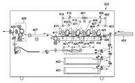
[プリンタ部202の構成]
図4に、プリンタ部202の概観図を示す。ポリゴンミラー401は、半導体レーザ駆動部から発光された4本のレーザ光を受ける。その内の1本のレーザ光はミラー402、403、404を経て感光ドラム405を走査する。別の1本のレーザ光はミラー406、407、408を経て感光ドラム409を走査する。更に別の1本のレーザ光はミラー410、411、412を経て感光ドラム413を走査する。更に別の1本のレーザ光はミラー414、415、416をへて感光ドラム417を走査する。
[Configuration of Printer Unit 202]
FIG. 4 shows an overview of the
一方、現像器418はイエロー(Y)のトナーを供給し、レーザ光の走査に応じて感光ドラム405上に形成された潜像を現像してイエローのトナー像を形成する。現像器419は、マゼンタ(M)のトナーを供給し、レーザ光の走査に応じて感光ドラム409上に形成された潜像を現像してマゼンタのトナー像を形成する。現像器420は、シアン(C)のトナーを供給し、レーザ光の走査に応じて感光ドラム413上に形成された潜像を現像してシアンのトナー像を形成する。更に、現像器421は、ブラック(B)のトナーを供給し、レーザ光の走査に応じて感光ドラム417上に形成された潜像を現像してブラックのトナー像を形成する。以上の4色(Y、M、C、K)のトナー像がシートに転写され、フルカラーの出力画像を得ることができる。
On the other hand, the developing
シートカセット422、423および、手差しトレイ424のいずれかより給紙されたシートは、レジストローラ425を経て、転写ベルト426上に吸着され、搬送される。給紙のタイミングと同期して、予め感光ドラム405、409、413、417には各色のトナーが現像されており、シートの搬送とともに、トナーがシートに転写される。各色のトナーが転写されたシートは、転写ベルト426から分離され、搬送ベルト427により定着器428に搬送される。定着器428では、トナーがシートに定着される。定着器428を抜けたシートは、フラッパ429により一旦下方向へ導かれてシートの後端がフラッパ429を抜けた後、スイッチバックさせて排出する。これによりフェースダウン状態で排出され、先頭頁から順にプリントしたときに正しいページ順となる。
A sheet fed from any of the
なお、4つの感光ドラム405、409、413、417は、距離dをおいて等間隔に配置されており、転写ベルト426によりシートは一定速度vで搬送される。このような位置関係と搬送速度に応じたタイミングに同期して感光ドラムにトナー像が形成されるように、ポリゴンミラー401や半導体レーザが駆動される。
The four
[フィニッシャ部205の構成]
図5に、フィニッシャ部205の概観図を示す。プリンタ部202の定着器428を経て排紙されたシートは、フィニッシャ部205に入る。フィニッシャ部205には、サンプルトレイ501及びスタックトレイ502があり、ジョブの種類や排出されるシートの枚数に応じて排出先のトレイが切り替わる。
[Configuration of Finisher 205]
FIG. 5 shows an overview of the
ソーティングの方式には2通りある。1つは、複数のビンを用いてジョブ毎に出力シートを各ビンに振り分けるビンソート方式である。他の1つは、後述の電子ソート機能と、ビン(またはトレイ)を図5の奥手前方向にシフトしてジョブ毎に出力シートを振り分けるシフトソート方式である。電子ソート機能は、コレートとも呼ばれる。装置内コントローラ204が大容量メモリ(例えば、画像メモリ304、HDD305)を有していれば、そのメモリを利用してバッファリングしたページ順と排出順を変更する、いわゆるコレート機能を用いることで電子ソーティングの機能をサポートできる。尚、グループ機能は、ソーティングがジョブ毎に振り分けるのに対し、ページ毎に仕分けする機能である。
There are two sorting methods. One is a bin sorting method that uses a plurality of bins to distribute output sheets to each bin for each job. The other one is an electronic sorting function, which will be described later, and a shift sorting method in which bins (or trays) are shifted forward in FIG. 5 and output sheets are sorted for each job. The electronic sort function is also called collate. If the in-
更に、スタックトレイ502に排出する場合には、シートが排出される前のシートを中間トレイ511に蓄えておき、複数部数のシートのうち1部のシートまたは1ジョブのシートごとにシート束をまとめてスタックトレイ502に排出する。また、ステイプルを実行するよう指定されている場合、中間トレイ511に蓄えられたシート束に対してステイプラ505によってステイプルを実行した後、シート束をスタックトレイ502に排紙する。その他、上記2つのトレイに至るまでに、紙をZ字状に折るためのZ折り機504、ファイル用の2つ(または3つ)の穴開けを行うパンチャ506があり、ジョブの種類に応じてそれぞれの処理を行う。更に、サドルステッチャ507は、シートの中央部分を2ヶ所バインドした後に、シートの中央部分をローラに噛ませることによりシートを半折りし、週刊誌やパンフレットのようなブックレットを作成する処理を行う。サドルステッチャ507で製本されたシートは、ブックレットトレイ508に排出される。その他、図5には記載されていないが、製本のためのグルー(糊付け)によるバインドや、あるいはバインド後にバインド側と反対側の端面を揃えるためのトリム(裁断)などのフィニッシャを加えることも可能である。
Further, when the sheets are discharged to the
また、インサータ503は、トレイ509にセットされたシートをプリンタを通さずにトレイ501、502、508のいずれかに送るためのものである。これによってフィニッシャ部205に送り込まれるシートとシートの間にインサータ503にセットされたシートをインサート(挿入)することができる。インサータ503のトレイ509には、インサートすべきシートがユーザによりフェースアップの状態でセットされ、ピックアップローラ510により最上部のシートから順にフィニッシャ部205内に給送される。従って、インサータ503からのシートをそのままトレイ501、502へ搬送することにより、フェースダウン状態で排出される。尚、サドルステッチャ507へ記録紙を送る場合は、一度パンチャ506側へ記録紙を送り込んだ後、スイッチバックさせて送り込むことによりフェースの向きを合わせる。
The
[外部コントローラ104]
次に、図6を用いて外部コントローラ104の構成、及びプリント時の動作を説明する。外部コントローラ104は、CPU601、ワークメモリ602、画像処理部603、画像メモリ604、大容量記憶装置(HDD)605、外部ネットワークI/F部606、内部ネットワークI/F部607、操作部613を含む。操作部613は、ユーザインタフェースを提供する。即ち、操作部613は、ユーザが外部コントローラ104の機能の実行を指示したり、機能実行時の動作設定を行うための入力デバイスを有する。また、操作部613は、外部コントローラ104の状態をユーザに知らせるためのディスプレイ等の表示部を備えている。
[External controller 104]
Next, the configuration of the
画像処理部603は、ビデオケーブル103を介しての画像形成装置101と接続されている。また、画像処理部603は、画像メモリ604とも接続されている。外部ネットワークI/F部606は、外部ネットワーク105に接続され、内部ネットワークI/F部607は、内部ネットワーク102に接続されている。CPU601は、HDD605に格納されたプログラムに従って動作し、ネットワークI/F部606、607を介して、コンピュータ端末106や画像形成装置101と通信し、所定の処理を実行する。また、CPU601は、操作部203からのユーザ指示/状態表示の処理を行なう。
The
続いて、コンピュータ端末106上の文書ファイルをプリントする際の、外部コントローラ104における動作(CPU601の制御)について説明する。外部コントローラ104は、外部ネットワークI/F部606を用いてコンピュータ端末106より送信されたPDLデータを外部ネットワーク105を介して受信する。外部ネットワークI/F部606によって受信されたPDLデータはHDD605に蓄積される。次に、CPU601は、画像処理部603を用いて、HDD605に蓄積されたPDLデータを画像メモリ604上にイメージとして展開する。そして、画像処理部603は、ビデオケーブル103を介して、展開されたイメージを画像形成装置101に転送する。このとき、CPU601は、当該展開されたイメージの印刷属性情報を、内部ネットワークI/F部607と内部ネットワーク102を介して、画像形成装置101に送信する。尚、印刷属性情報には、展開されたイメージのサイズなどの情報や、PDLデータに含まれる画像形成装置101にて実施されるプリント時の設定等が含まれている。こうして、外部コントローラ104から送信された印刷属性情報と展開されたイメージとに基づいて、画像形成装置101はイメージをシート(記録媒体)上に印刷する。
Next, an operation (control of the CPU 601) in the
[ジョブ投入の概要シーケンス(フラッシュ動作を含む)]
次に、本実施形態における特徴的なフラッシュ機能の動作を含むジョブ投入について、処理の概要シーケンス例を図7を用いて説明する。図7は、図1の外部コントローラ104と画像形成装置101とで、内部ネットワーク102を介して行われる処理シーケンスの一例を示している。
[Overview sequence of job submission (including flash operation)]
Next, job input including the operation of the characteristic flash function in this embodiment will be described with reference to FIG. FIG. 7 shows an example of a processing sequence performed via the
図7は、4ページの印刷ジョブのページデータが投入指示される場合のシーケンスである。画像形成装置101は、受信した印刷ジョブのページデータをHDD305に記憶し、記憶されたページデータに基づいて印刷を実行する。印刷ジョブが複数ページのページデータを有する場合、画像形成装置101は、複数のページデータに基づいて印刷を実行する。画像形成装置101では、1ページ目の用紙は中間トレイ511に排紙完了し、2ページ目の用紙を給紙後、中間トレイ511に排紙完了する前にジョブ中断要因が発生している。このジョブ中断要因は、例えば、ジャムエラーや紙無しなどである。画像形成装置101でのジョブの中断の発生を受けた後、外部コントローラ104からフラッシュ指示がなされる。このフラッシュ指示を受けると、画像形成装置101は、ジョブのページデータを全て削除する。すなわち、この例のフラッシュ処理とは、画像形成装置101に存在する印刷中のジョブのページデータを削除する処理である。そして、印刷中のページデータが削除された後、ユーザは、外部コントローラ104から、ジョブの設定の変更や、変更後の設定に基づいたサンプル印刷の指示を行うことができる。そして、その後、外部コントローラ104は、ユーザからの指示に従って、ジョブの設定とともに、再度、2〜4ページ目のページデータを画像形成装置101に送信する。
FIG. 7 is a sequence in a case where page data of a 4-page print job is instructed. The
図7は、上(S701)から下(S719)に向かって順に、処理が実行されていることを示す。また矢印で示す各処理は、矢印の根元側が、矢印の先側に対して、指示や通知を行っていることを示す。まずS701では、外部コントローラ104から画像形成装置101へのジョブ開始指示がなされ、画像形成装置101でジョブ#1が生成される。
FIG. 7 shows that processing is executed in order from the top (S701) to the bottom (S719). Each process indicated by an arrow indicates that the root side of the arrow is giving an instruction or notification to the tip side of the arrow. First, in step S <b> 701, a job start instruction is issued from the
そして、S702では、外部コントローラ104から画像形成装置101へのジョブの設定指示が行われる。ここでは、画像形成装置101にて実施されるプリント時の動作設定の指示が行われる。このジョブの設定には、ステイプル処理をするか否か、どの位置にステイプルするか、などといった設定も含まれる。この例では、左上(TopLeft)へのステイプル設定の指示を含んでいる。そして、続くS703〜S706は、外部コントローラ104から画像形成装置101へのページ投入指示が行われる。ここでは4回ページ投入され、画像形成装置101にはページ#1〜ページ#4の4ページが投入されたことになる。
In step S <b> 702, a job setting instruction is issued from the
その後、S707では、画像形成装置101から外部コントローラ104への、ジョブ中断発生通知が行われる。図7では、画像形成装置101でジャムや紙無しなど何らかのジョブ中断要因が発生したことを、外部コントローラ104に対して通知している。そして、S708では、外部コントローラ104から画像形成装置101へのフラッシュ指示が行われる。このフラッシュ指示は、後述する図8のS809で画像形成装置101へ送信する指示に相当する。本実施形態では、外部コントローラ104は、画像形成装置101からジョブ中断発生通知を受信すると、フラッシュ指示を行う仕組みになっている。なお、外部コントローラ104がフラッシュ指示を行うのは、ジョブ中断発生通知の受信に応じたものに限る必要はない。例えば、ユーザから外部コントローラ104に対する入力によって、外部コントローラ104から画像形成装置101にフラッシュ指示を行うようにしても良い。
Thereafter, in step S <b> 707, a job interruption occurrence notification is performed from the
S709〜S712では、画像形成装置101から外部コントローラ104への、ページ状況通知が行われる。ここでは4回通知されており、これはS701のジョブ開始指示に始まったジョブ#1の、S703〜S706で投入された4ページ分の各ページの状況を通知している(図8のS831に対応)。各ページの状況とは、「印刷済」、「給紙済」、「削除」のいずれかである。「印刷済」は、そのページが印刷されてフィニッシャ部205の中間トレイ511などの排出先に排紙完了している状況を示す。「給紙済」は、シートカセットあるいは手差しトレイなどの給紙先のいずれかより給紙されてはいるが、排出先に排紙完了はしていない状況を示す。また「削除」は、そのページが給紙されないまま、ページデータが削除された状況を示す(ページデータの削除は、図8のS830に対応)。
In S709 to S712, a page status notification is made from the
S709ではページ#1が印刷済であることを通知し、S710ではページ#2が給紙済であるが排紙完了していないことを通知している。つまり、ページ#2は、画像形成装置101内に残留していることを示している。またS711ではページ#3が、S712ではページ#4が、それぞれ削除されたことを通知している。そして、S713では、画像形成装置101から外部コントローラ104への、フラッシュ処理完了通知が行われる。つまり、一連のフラッシュ処理が完了したことを通知している。
In step S709, it is notified that
S714では、外部コントローラ104から画像形成装置101へのジョブの設定指示が行われる。これはS702と同様の指示である。この例では、右上(TopRight)へのステイプル設定の指示を含んでいる。つまり、ステイプルの設定が左上(TopLeft)から右上(TopRight)に変更されている。
In step S <b> 714, a job setting instruction is issued from the
そして、S715〜S717では、外部コントローラ104から画像形成装置101へのページ投入指示が行われる。ここでは3回ページ投入され、画像形成装置101にはページ#2〜ページ#4の3ページが投入されたことになる。これは、ユーザの指示を受けて、S703〜S706で投入したページ#1〜ページ#4の4ページのうち、印刷済ではなかった後半3ページを投入していることになる。
In steps S <b> 715 to S <b> 717, a page input instruction is issued from the
以上のシーケンスにより、画像形成装置101には、ページ#1〜ページ#4の4ページのプリントアウトが、排紙されたことになる。S718では、外部コントローラ104から画像形成装置101へのジョブ終了指示が行われ、S719では、画像形成装置101から外部コントローラ104へのジョブ終了通知が行われる。
Through the above sequence, the four-page printout of
[ジョブ投入フロー(フラッシュ指示とその後の継続印刷指示を含む)]
次に、図8のS801〜S817を用いて外部コントローラ104のジョブ投入の動作を説明する。図8に示されるS801〜S817の各ステップの処理は、外部コントローラ104によって実行されるジョブ投入の処理である。フラッシュ指示とその後の継続印刷の処理も含んでいる。各ステップの処理は、外部コントローラ104のCPU601が、HDD605に格納された制御プログラムをワークメモリ602にロードして実行することにより実現される。
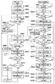
[Job submission flow (including flash instructions and subsequent continuous printing instructions)]
Next, the job input operation of the
まずS801で外部コントローラ104は、画像形成装置101にジョブ開始の指示を送信する(図7のS701に対応)。そして、S802で外部コントローラ104は、画像形成装置101にジョブ設定の指示を送信する(図7のS702に対応)。そして、S803において、外部コントローラ104は、最初のページに注目する。そして、S804で、外部コントローラ104は、画像形成装置101に、注目ページのページ投入指示を送信する。そして、S805で、外部コントローラ104は、中断発生通知を画像形成装置101から受信したか否かを判定する。ここで、中断発生通知を受信していないと判定された場合、S806で、外部コントローラ104は注目ページの次のページがあるか否かを判定する。ここで、次のページがあると判定された場合、S807で次のページに注目して、S804からの処理を繰り返す。これにより、最初のページ以降のページを画像形成装置101に送信することになる(図7のS703〜S706に対応)。
First, in step S801, the
一方、S806において次のページが無いと判定された場合、画像形成装置101に全ページのページ投入指示を送信し終えたことになる。そこで、S808に進み、外部コントローラ104は、ジョブ終了指示を画像形成装置101に送信し、一連の処理を完了する。
On the other hand, if it is determined in S806 that there is no next page, it means that the page input instruction for all pages has been transmitted to the
S805において中断発生通知を受信したと判定された場合、外部コントローラ104は、S809において画像形成装置101にフラッシュ指示を送信する(図7のS708に対応)。そしてS810で、画像形成装置101からのページ状況の通知を受け付ける。受け付けた通知の内容は、ワークメモリ602あるいはHDD605に格納して、必要時に参照することができる。
If it is determined in S805 that the interruption occurrence notification has been received, the
そして、S811において、画像形成装置101からのフラッシュ完了通知を受信したか否かを判定する(図7のS713に対応)。フラッシュ完了通知を受信していないと判定された場合、外部コントローラ104は、再びS810に戻り、S811でフラッシュ完了通知を受信したと判定するまで繰り返す。
In step S811, it is determined whether a flash completion notification is received from the image forming apparatus 101 (corresponding to step S713 in FIG. 7). If it is determined that the flash completion notification has not been received, the
一方、S811で、画像形成装置101からフラッシュ完了通知を受信したと外部コントローラ104が判定した場合、S812へ進む。S812において、外部コントローラ104は、操作部613にユーザに「継続印刷」についての入力を促す表示をする。ユーザに「継続印刷」についての入力を促す表示については後述する。
On the other hand, if the
そしてS813で外部コントローラ104は、継続印刷に対するユーザの入力を受け付け終えたか否かを判定する。後述するが、印刷キー902あるいはジョブキャンセルキー901のいずれかが押下されたら、ユーザの入力を受け付け終えたと判定する。
In step S813, the
ここで入力を受け付け終えたと判定されるまで、S813を繰り返す。外部コントローラ104が、S813で入力を受け付け終えたと判定した場合、S814に進む。S814で、外部コントローラ104は、ユーザが「ジョブキャンセル」を入力したか否かを判定する。ユーザが「ジョブキャンセル」を入力したと判定された場合、外部コントローラ104は、S817に進む。S817で、外部コントローラ104は、画像形成装置101にジョブキャンセル指示を送信する。そして、一連の処理を終了する。
Here, S813 is repeated until it is determined that the input has been received. If the
一方、S814でユーザが「ジョブキャンセル」を入力していない、すなわち「続きを印刷」をユーザが入力したと判定された場合、S815に進む。S815で外部コントローラ104は、画像形成装置101にジョブ設定の指示を送信する(図7のS714に対応)。ここで、図9を用いて後述するステイプルの動作設定の表示画面で、ユーザが入力したステイプルを行うかどうか、および、ステイプル位置の設定の指示も送信される。
On the other hand, if it is determined in step S814 that the user has not input “job cancel”, that is, the user has input “continue printing”, the process advances to step S815. In step S815, the
そして、S816において、外部コントローラ104は、ユーザの入力した継続印刷の開始ページに注目する。これは、上述のS813において、継続印刷の入力画面でユーザが入力していたページである。そして、S804に戻り、外部コントローラ104は、注目ページのページ投入指示を画像形成装置101に送信するところからの処理を繰り返す。これにより、ユーザが入力した継続印刷の開始ページ以降のページを画像形成装置101に送信することになる(図7のS715〜S717に対応)。
In step S816, the
一方、S814でユーザが「ジョブキャンセル」を入力したと判定された場合、S817において外部コントローラ104は、ジョブキャンセル指示を画像形成装置101に送信する。このジョブキャンセル指示を受信した画像形成装置101は、そのジョブをキャンセルして処理を終了する。そして、外部コントローラ104は、一連のジョブ投入の処理を完了する。
On the other hand, if it is determined in step S814 that the user has input “job cancel”, the
以上により、外部コントローラ104は、ジョブを投入中に中断発生通知を受けると画像形成装置101にフラッシュ指示をする。そして、画像形成装置101でのフラッシュ処理が完了した後、ユーザから受け付けた入力に従って、ステイプルなどの設定および継続印刷するページを画像形成装置101に送信するよう動作する。
As described above, the
[印刷動作フロー]
次に、図8のS821〜S838を用いて画像形成装置101の印刷制御動作を説明する。図8に示されるS821〜S838の各処理は、画像形成装置101の装置内コントローラ204によって実行される。更に詳しくは、例えば、装置内コントローラ204のCPU301が、HDD305に格納された制御プログラムをワークメモリ302にロードして実行することにより実現される。
[Printing operation flow]
Next, the print control operation of the
まずS821で装置内コントローラ204は、ジョブ開始指示を受信したか否かを判定する。ここで、ジョブ開始指示を受け取ったと判定されるまで、S821を繰り返す。S821でジョブ開始指示を受信したと判定された場合、S822において、装置内コントローラ204は新規のジョブを生成する。
In step S821, the in-
そして、S823で、装置内コントローラ204は、ジョブ設定指示を受信したか否かを判定する。ここで、ジョブ設定指示を受信したと判定されるまで、S823を繰り返す。S823でジョブ設定指示を受信したと判定された場合、S824において、装置内コントローラ204は、受け取ったジョブ設定に基づいて、印刷処理で動作すべき画像の向きを判定する。例えば、受け取った画像データをそのまま印刷すれば良いのか、画像の回転処理をして向きを変更してから印刷する必要があるのかを判定する。これは、ステイプルをする設定の場合に、設定されたステイプル位置がステイプル装置の機構的にそのままの向きでステイプルできる位置であるか否かに基づき判定する。そして、S825で、装置内コントローラ204は、受け取ったジョブ設定と、判定された結果の画像の向きとを、このジョブの情報として保持する。
In step S823, the in-
そして、S826において装置内コントローラ204は、ページ投入指示を受信したか否かを判定する。ここで、S826においてページ投入指示を受信したと判定された場合、S827で、保持した画像の向きに従った向きでページ画像を格納する。例えば、画像処理部303は、保持した画像向きになるように、入力された画像データに必要な回転処理を行ったうえで、HDD305に格納する。そして、S826に戻る。一方、S826においてページ投入指示を受信していないと判定した場合、S828で装置内コントローラ204は、ジョブ終了指示を受信したか否かを判定する。ここで、ジョブ終了指示を受信したと判定した場合、一連の処理を完了する。
In step S826, the in-
一方、S828でジョブ終了指示を受信していないと判定された場合、装置内コントローラ204は、S829でフラッシュ指示を受信したか否かを判定する。ここで、フラッシュ指示とは、上述したS809で、外部コントローラ104が画像形成装置101に送信した指示のことである。
On the other hand, if it is determined in S828 that the job end instruction has not been received, the in-
S829でフラッシュ指示を受信したと判定されると、装置内コントローラ204は、S830において、ジョブのページデータを全て削除する。そして、S831で、各ページの状況を外部コントローラ104へ送信する。
If it is determined in S829 that the flush instruction has been received, the in-
そして、S831で各ページの状況通知を終えると、装置内コントローラ204は、S832に処理を進め、外部コントローラ104へフラッシュ完了通知を送信する。このフラッシュ完了通知を外部コントローラ104が受信すると、上述したように、外部コントローラ104は、S811からS812へと処理を進める。そして、S833で、装置内コントローラ204は、ジョブ設定指示を受け取ったか否かを判定する。ここで、ジョブ設定指示を受け取ったと判定されるまで、S833を繰り返す。装置内コントローラ204が、S833でジョブ設定指示を受け取ったと判定された場合、S834に処理を進める。S834で、装置内コントローラ204は、受け取ったジョブ設定に基づいて、新しい画像の向きを判定する。この判定は、S824と同様の処理である。そしてS835で、装置内コントローラ204は、新しい画像の向きが、保持してある前半の画像の向きと同じか否かを判定する。
When the status notification of each page is completed in S831, the in-
S835で装置内コントローラ204が、新しい画像の向きが前半(つまり、設定の変更前)の向きと同じであると判定した場合、S825に戻り、ジョブ設定と画像の向きをジョブの情報として上書きして保持するところから処理を続ける。つまり、結果的に、画像の向きは変わらずに出力される。この場合、装置内コントローラ204は、中間トレイ511に蓄えられたシート束を、1部のページデータの印刷または1ジョブのページデータの印刷が完了した後に、ステイプラ505によってステイプルするよう制御する。そして、装置内コントローラ204は、ステイプルされたシート束をスタックトレイ502に排紙するよう制御する。
If the in-
一方、S835で装置内コントローラ204が、新しい画像の向きが前半の向きと同じではないと判定した場合、S836で、ステイプルを強制的にオフに設定する(行わないよう設定する)。そして、S837で、装置内コントローラ204は、画像の向きは前半と同じ向きのままとする。この場合、装置内コントローラ204は、中間トレイ511に蓄えられたシート束を、1部のページデータの印刷または1ジョブのページデータの印刷が完了した後に、ステイプラ505によってステイプルしないよう制御する。そして、装置内コントローラ204は、ステイプルしないまま中間トレイ511に蓄えられたシート束をスタックトレイ502に排紙するよう制御する。そして、S838で、操作部203に、ユーザに「ステイプルをしないで向きを揃えて印刷出力した旨」を知らせる注意の表示を行う。例えば、図10に示すような表示である。そして、S825に戻り、受け取ったジョブ設定と画像の向き(前半と同じ向き)をジョブの情報として上書きして保持するところから処理から続ける。つまり、結果的に、画像の向きは変わらずに出力される。
On the other hand, if the in-
以上のように、画像形成装置101は、外部コントローラ104からのフラッシュ指示に応じて、画像形成装置内の各ジョブに対してフラッシュ処理を行う。フラッシュ処理は、ジョブはキャンセルせずに存続させたまま、ジョブのページデータは削除するように動作する処理である。そして、画像形成装置101は、継続印刷時のステイプル設定に応じて、印刷処理で動作すべき画像の向きを判定する。そして、その画像の向きが前半の画像の向きと異なる場合には、強制的にステイプルをオフ(行わない)設定に変更して、かつ、画像の向きは前半と同じ向きのままで印刷するよう、後半の継続印刷を制限する。
As described above, the
[ユーザに入力を促す表示]
次に、図9(a)、(b)を利用して、外部コントローラ104がユーザに「継続印刷」についての入力を促す表示について説明する。図9(a)は、外部コントローラ104が、ユーザに「継続印刷」についての入力を促すために操作部613に表示する画面の一例である。ここで、継続印刷の開始ページフィールド903は、「続きを印刷」キー902が押された場合に、どのページから継続印刷を開始するかを示す。この継続印刷の開始ページフィールド903は、ユーザが数値を変更することが可能である。図9(a)では2ページ目から、継続印刷を開始する場合の表示例が示されている。
[Prompt for user input]
Next, a display in which the
ここで、ステイプル指定キー904が押下されると、図9(b)の画面に遷移し、ステイプルに関する設定を行うことができる。また、ジョブキャンセルキー901が押下されると、外部コントローラ104から画像形成装置101に対してジョブキャンセル指示が通知されることになる(図8のS817に対応)。「続きを印刷」キー902が押下されると、外部コントローラ104は、各フィールドで設定された値に応じて、継続印刷の処理を行う。なお、「続きを印刷」キー902、ジョブキャンセルキー901のいずれかが押下されると、継続印刷に対する入力が完了し、ユーザの入力を受け付け終えたことになる。
Here, when the
次に、図9(b)は、外部コントローラ104が、ユーザに「ステイプル指定」についての入力を促すために、操作部613に表示する画面の一例である。図9(a)のステイプル指定キー904が押下されると、図9(b)のステイプル指定の画面に遷移する。
Next, FIG. 9B is an example of a screen displayed on the
図9(b)において、「ステイプルしない」選択キー913を押すことにより、ステイプルしないことを設定することができる。また、コーナー選択キー914を押下することにより、出力束の1角に1箇所ステイプル処理するコーナーステイプルモードが選択され、左上キー916、左下キー917、右上キー918、右下キー919が表示される。それらのキーを押すことにより、ステイプル位置を出力束の左上、左下、右上、右下の何れかのコーナーに設定することができる。ダブル選択キー915を押下することにより、出力束の1辺に2箇所ステイプル処理するダブルステイプルモードが選択され、不図示の左側2個所綴じキー、右側2個所綴じキーが表示される。それらのキーを押すことにより、ステイプル位置を出力束の左側2個所綴じ、右側2個所綴じの何れかに設定することができる。
In FIG. 9B, it can be set not to staple by pressing a “do not staple”
図9(b)の例では、左上ステイプルが選択されている。また、ユーザは、所望するステイプル位置に設定を変更することが可能である。また、OKキー912で、図9(b)の画面の設定内容を有効にし、キャンセルキー911で、図9(b)の画面の設定内容を無効にする。そして、いずれの場合も図9(a)の画面に戻る。
In the example of FIG. 9B, the upper left staple is selected. Further, the user can change the setting to a desired stapling position. Further, the setting contents of the screen of FIG. 9B are validated with the
図11は、画像形成装置101における各コーナーステイプルモードの実現方法の一例を示す模式図である。画像形成装置101では、フィニッシャ部205はステイプラ505を備えており、そのステイプラ505が用紙搬送方向に対し、垂直方向に奥側、手前側に移動できる構成になっている。そして、図11に示すように、左上ステイプル、左下ステイプルは、上述した奥側、手前側とステイプルの位置を使い分けることで実現される。一方、右上ステイプル、右下ステイプルはそのままでは実現できないため、画像回転処理を用いて、180度の画像回転を行い、さらに、上述した奥側、手前側とステイプルの位置を使い分けることで実現される。
FIG. 11 is a schematic diagram illustrating an example of a method for realizing each corner stapling mode in the
図7のシーケンスの場合、図8のS812において、外部コントローラ104は操作部613に、まず図9(a)のような初期表示を行ってユーザの入力を促す。ユーザは、上述したような操作をすることによって、継続印刷に関する所望の設定を入力することができる。なお、ここで初期表示するページは、この例に限らず、どのようなページを表示するようにしても構わない。この例では、画像形成装置101からのページ状況通知で、ページ#1のみが印刷済であったため、印刷済では無い先頭のページであるページ#2を、継続印刷の開始ページフィールド903に初期表示している。そして、フィールド905には、「続きを印刷」キー902が押されるとどのページが印刷されるのかを模式的に表示している。ここでは、ページ#2以降を継続印刷する、ということを示している。すなわち、図9(a)の画面において、「続きを印刷」キー902が押されると、図7のシーケンスで示した通り、S714、S715、S716、S717の順で外部コントローラ104から画像形成装置101へ指示が行われる。例えば、もしユーザが、継続印刷を開始するのをページ#3からに変更したい場合には、継続印刷の開始ページフィールド903の値を「3」に変更すれば良い。
In the case of the sequence of FIG. 7, in step S812 of FIG. 8, the
以上説明したように、出力束の途中での設定変更指示により、排紙済の前半の画像の向きと設定変更後の後半の画像の向きが異なる場合には、画像形成装置101は、後半の画像の向きを前半と同じ向きにし、かつ、ステイプル処理を行わないように制御する。それにより、束全体の画像の向きが混在する印刷物の生成を回避できる。
As described above, when the direction of the first half of the discharged paper is different from the direction of the second half of the image after the setting change due to the setting change instruction in the middle of the output bundle, the
〔第2実施形態〕
第1実施形態では、外部コントローラ104から画像形成装置101に、ユーザの所望する任意のステイプル位置の設定に変更する指示が可能な例を示した。しかし、画像形成装置101で画像回転処理が必要となるステイプル位置への設定変更を、あらかじめ外部コントローラ104側で禁止するようにしても構わない。以下、その構成について、説明する。なお、画像形成装置101の構成は上記第1実施形態を同様である。
[Second Embodiment]
In the first embodiment, an example in which the
図8のS812において、前半部の印刷時の画像回転とは異なる回転が必要となるステイプル位置の設定を、外部コントローラ104で禁止する処理を行うことで実現される。
In step S812 in FIG. 8, the
以下、図12を用いて説明する。図12は、外部コントローラ104の操作部613において、設定禁止を実現する設定画面の一例を示す模式図である。図12は、図9(b)に示したステイプル指定の画面に対応し、図9(b)と同一のものには同一の符号を付してある。
Hereinafter, a description will be given with reference to FIG. FIG. 12 is a schematic diagram illustrating an example of a setting screen that realizes setting prohibition in the
例えば前半部が左上指定(回転角度0度)であった場合、図12に示すように回転角度が180度(前半部と異なる)となる右上コーナーステイプルや右下コーナーステイプルの各設定キー918、919を網掛け処理して設定不可なように表示する。前半部と同じ回転角度0度である左下コーナステイプルは設定可能なように表示される。同様にして、前半部が右上指定(回転角度180度)であった場合には、回転角度が0度となる左上コーナーステイプル、左下コーナーステイプルの各設定キー916、917を網掛け処理して、設定受付不可なように表示する。
For example, when the upper half is designated at the upper left (rotation angle 0 degree), as shown in FIG. 12, the setting
以上説明したように、出力束の途中での設定変更を指示する場合に、外部コントローラで、排紙済の前半の画像の向きと設定変更後の後半の画像の向きが異なるような設定変更を選択できないように制御する。それにより、束全体の画像の向きが混在する印刷物の生成を回避できる。 As described above, when instructing to change the setting in the middle of the output bundle, the external controller must change the setting so that the orientation of the first half of the ejected image differs from the orientation of the second half of the image after the setting change. Control so that it cannot be selected. As a result, it is possible to avoid the generation of a printed material in which the orientation of the images of the entire bundle is mixed.
第1実施形態および第2実施形態では、外部コントローラ104によって印刷ジョブをイメージに展開し、これを画像形成装置101のHDD305に蓄積するが、これに限られるものではない。画像形成装置101がプリンタとしての機能を有し、コンピュータ端末106から送られてきたプリントジョブを自身でイメージへ展開してHDD305に蓄積するようにしても良い。そして、コンピュータ端末106がフラッシュ指示とその後の継続印刷をする機能を有するようにしてもよい。この場合、外部コントローラ104を省略できる。
In the first and second embodiments, the print job is developed into an image by the
上述した実施形態では、フィニッシャ205によるフィニッシング(後処理)として、ステイプルを例に挙げて説明したが、本発明はこれに限らない。例えば、フィニッシングの位置が変更されたことによって画像の向きが変わるものであれば、フィニッシングの種類はステイプルに限らない。例えば、フィニッシングの種類はパンチ処理であってもよい。
In the embodiment described above, the finishing (post-processing) by the
本発明は、以下の処理を実行することによっても実現される。即ち、上述した実施形態の機能を実現するソフトウェア(プログラム)を、ネットワーク又は各種記憶媒体を介してシステム或いは装置に供給し、そのシステム或いは装置のコンピュータ(またはCPUやMPU等)がプログラムを読み出して実行する処理である。 The present invention is also realized by executing the following processing. That is, software (program) that realizes the functions of the above-described embodiments is supplied to a system or apparatus via a network or various storage media, and a computer (or CPU, MPU, or the like) of the system or apparatus reads the program. It is a process to be executed.
Claims (12)
前記印刷手段により開始された前記複数枚の印刷用紙の印刷中に、前記フィニッシング設定の変更を受け付ける受付手段と、
当該変更された前記フィニッシング設定を実行すると、当該変更前に印刷された画像の向きと異なる向きの画像を印刷するか否かを判定する判定手段と、
前記判定手段により、当該変更前に印刷された画像の向きと異なる向きの画像を印刷すると判定された場合、当該変更された前記フィニッシング設定の実行を制限する制限手段と、
を備えることを特徴とする画像形成装置。 Printing means for starting printing in a state where finishing settings are made on a plurality of printing papers;
Receiving means for accepting a change in the finishing setting during printing of the plurality of printing sheets started by the printing means;
When executing the changed finishing setting, a determination unit that determines whether or not to print an image having a direction different from the direction of the image printed before the change,
When the determination unit determines to print an image having a direction different from the direction of the image printed before the change, a limiting unit that limits execution of the changed finishing setting;
An image forming apparatus comprising:
複数枚の印刷用紙に対してフィニッシング設定がなされた状態で印刷を開始する印刷工程と、
前記印刷工程で開始された前記複数枚の印刷用紙の印刷中に、前記フィニッシング設定の変更を受け付ける受付工程と、
当該変更された前記フィニッシング設定を実行すると、当該変更前に印刷された画像の向きと異なる向きの画像を印刷するか否かを判定する判定工程と、
前記判定工程で、当該変更前に印刷された画像の向きと異なる向きの画像を印刷すると判定された場合、当該変更された前記フィニッシング設定の実行を制限する制限工程と、
を有することを特徴とする印刷制御方法。 A printing control method executed by an image forming apparatus,
A printing process in which printing is started in a state where finishing settings are made on a plurality of printing papers;
An accepting step of accepting a change in the finishing setting during printing of the plurality of printing sheets started in the printing step;
A determination step of determining whether or not to print an image having a different orientation from the orientation of the image printed before the change, when executing the changed finishing setting;
In the determination step, when it is determined to print an image having a direction different from the direction of the image printed before the change, a restriction step for restricting execution of the changed finishing setting;
A printing control method characterized by comprising:
前記印刷手段により開始された前記複数枚の印刷用紙の印刷が中断した場合に、前記フィニッシング設定を変更して実行すると、当該変更前に印刷された画像の向きと異なる向きの画像を印刷するか否かを判定する判定手段と、
前記判定手段により、当該変更前に印刷された画像の向きと異なる向きの画像を印刷すると判定された場合、当該変更される前記フィニッシング設定の実行を制限する制限手段と、
を備えることを特徴とする画像形成装置。 Printing means for starting printing in a state where finishing settings are made on a plurality of printing papers;
If printing of the plurality of printing sheets started by the printing unit is interrupted, if the finishing setting is changed and executed, an image with a direction different from the orientation of the image printed before the change is printed. Determining means for determining whether or not;
A limiting unit that limits execution of the finishing setting to be changed when the determination unit determines to print an image having a direction different from the direction of the image printed before the change;
An image forming apparatus comprising:
複数枚の印刷用紙に対してフィニッシング設定がなされた状態で印刷を開始する印刷工程と、
前記印刷工程で開始された前記複数枚の印刷用紙の印刷が中断した場合に、前記フィニッシング設定を変更して実行すると、当該変更前に印刷された画像の向きと異なる向きの画像を印刷するか否かを判定する判定工程と、
前記判定工程で、当該変更前に印刷された画像の向きと異なる向きの画像を印刷すると判定された場合、当該変更される前記フィニッシング設定の実行を制限する制限工程と、
を有することを特徴とする印刷制御方法。 A printing control method executed by an image forming apparatus,
A printing process in which printing is started in a state where finishing settings are made on a plurality of printing papers;
If printing of the plurality of printing sheets started in the printing process is interrupted and the finishing setting is changed and executed, an image with a different orientation from the orientation of the image printed before the change is printed. A determination step of determining whether or not,
If it is determined in the determination step that an image having a direction different from the direction of the image printed before the change is printed, a restriction step for restricting execution of the finishing setting to be changed;
A printing control method characterized by comprising:
複数枚の印刷用紙に対してフィニッシング設定がなされた状態で印刷を開始するように前記画像形成装置に指示する指示手段と、
前記指示手段により開始された前記複数枚の印刷用紙の印刷が中断した場合に、前記フィニッシング設定を変更して実行すると、当該変更前に印刷された画像の向きと異なる向きの画像を印刷するか否かを判定する判定手段と、
前記判定手段により、当該変更前に印刷された画像の向きと異なる向きの画像を印刷すると判定された場合、当該変更される前記フィニッシング設定の実行を制限する制限手段と、
を備えることを特徴とする印刷制御装置。 A print control apparatus that instructs the image forming apparatus to print,
Instruction means for instructing the image forming apparatus to start printing in a state where finishing settings are made on a plurality of printing papers;
If printing of the plurality of printing sheets started by the instruction unit is interrupted, if the finishing setting is changed and executed, an image with a different orientation from the orientation of the image printed before the change is printed. Determining means for determining whether or not;
A limiting unit that limits execution of the finishing setting to be changed when the determination unit determines to print an image having a direction different from the direction of the image printed before the change;
A printing control apparatus comprising:
複数枚の印刷用紙に対してフィニッシング設定がなされた状態で印刷を開始するように前記画像形成装置に指示する指示工程と、
前記指示工程で開始された前記複数枚の印刷用紙の印刷が中断した場合に、前記フィニッシング設定を変更して実行すると、当該変更前に印刷された画像の向きと異なる向きの画像を印刷するか否かを判定する判定工程と、
前記判定工程で、当該変更前に印刷された画像の向きと異なる向きの画像を印刷すると判定された場合、当該変更される前記フィニッシング設定の実行を制限する制限工程と、
を有することを特徴とする印刷制御方法。 A print control method executed by a print control device that instructs printing to an image forming apparatus,
An instruction step for instructing the image forming apparatus to start printing in a state where the finishing setting is made on a plurality of printing papers;
If printing of the plurality of printing sheets started in the instruction step is interrupted, if the finishing setting is changed and executed, an image with a direction different from the orientation of the image printed before the change is printed. A determination step of determining whether or not,
If it is determined in the determination step that an image having a direction different from the direction of the image printed before the change is printed, a restriction step for restricting execution of the finishing setting to be changed;
A printing control method characterized by comprising:
Priority Applications (2)
| Application Number | Priority Date | Filing Date | Title |
|---|---|---|---|
| JP2013125009A JP6122349B2 (en) | 2013-06-13 | 2013-06-13 | Image forming apparatus, printing control method, and program |
| US14/290,770 US9211694B2 (en) | 2013-06-13 | 2014-05-29 | Image forming apparatus, print control method and storage medium storing program |
Applications Claiming Priority (1)
| Application Number | Priority Date | Filing Date | Title |
|---|---|---|---|
| JP2013125009A JP6122349B2 (en) | 2013-06-13 | 2013-06-13 | Image forming apparatus, printing control method, and program |
Publications (3)
| Publication Number | Publication Date |
|---|---|
| JP2015000493A JP2015000493A (en) | 2015-01-05 |
| JP2015000493A5 JP2015000493A5 (en) | 2016-07-28 |
| JP6122349B2 true JP6122349B2 (en) | 2017-04-26 |
Family
ID=52018563
Family Applications (1)
| Application Number | Title | Priority Date | Filing Date |
|---|---|---|---|
| JP2013125009A Expired - Fee Related JP6122349B2 (en) | 2013-06-13 | 2013-06-13 | Image forming apparatus, printing control method, and program |
Country Status (2)
| Country | Link |
|---|---|
| US (1) | US9211694B2 (en) |
| JP (1) | JP6122349B2 (en) |
Families Citing this family (3)
| Publication number | Priority date | Publication date | Assignee | Title |
|---|---|---|---|---|
| JP6593218B2 (en) * | 2016-02-18 | 2019-10-23 | コニカミノルタ株式会社 | Image forming system, image forming apparatus, post-processing apparatus, and control method thereof |
| JP7283252B2 (en) * | 2019-06-21 | 2023-05-30 | コニカミノルタ株式会社 | Print controller and program |
| JP2022029234A (en) * | 2020-08-04 | 2022-02-17 | 京セラドキュメントソリューションズ株式会社 | Print job transmission device and print job transmission program |
Family Cites Families (10)
| Publication number | Priority date | Publication date | Assignee | Title |
|---|---|---|---|---|
| JP3125680B2 (en) * | 1996-05-28 | 2001-01-22 | 富士ゼロックス株式会社 | Post-processing device for image forming apparatus |
| JP3766164B2 (en) | 1997-03-03 | 2006-04-12 | 株式会社リコー | Image forming apparatus |
| DE69837583T2 (en) * | 1997-09-11 | 2007-12-27 | Canon K.K. | Printer control system and method |
| JP3782588B2 (en) * | 1997-09-11 | 2006-06-07 | キヤノン株式会社 | Information processing apparatus, host computer, and processing method in information processing apparatus |
| JP2002101254A (en) * | 2000-09-22 | 2002-04-05 | Konica Corp | Picture forming device |
| JP2005329624A (en) * | 2004-05-20 | 2005-12-02 | Konica Minolta Business Technologies Inc | Image forming apparatus |
| JP2008006692A (en) * | 2006-06-29 | 2008-01-17 | Konica Minolta Business Technologies Inc | Image forming system |
| JP2008012755A (en) * | 2006-07-05 | 2008-01-24 | Kyocera Mita Corp | Image forming system and image formation method |
| JP2011048084A (en) * | 2009-08-26 | 2011-03-10 | Konica Minolta Business Technologies Inc | Image forming apparatus, post-processing control method, and post-processing control program |
| JP2011140204A (en) * | 2010-01-09 | 2011-07-21 | Konica Minolta Business Technologies Inc | Image forming apparatus and image forming system |
-
2013
- 2013-06-13 JP JP2013125009A patent/JP6122349B2/en not_active Expired - Fee Related
-
2014
- 2014-05-29 US US14/290,770 patent/US9211694B2/en not_active Expired - Fee Related
Also Published As
| Publication number | Publication date |
|---|---|
| JP2015000493A (en) | 2015-01-05 |
| US20140367907A1 (en) | 2014-12-18 |
| US9211694B2 (en) | 2015-12-15 |
Similar Documents
| Publication | Publication Date | Title |
|---|---|---|
| KR101239522B1 (en) | Printing control apparatus and information processing apparatus and method for controlling a printing apparatus and method for controlling an information processing apparatus and computer-readable storage medium | |
| US8289534B2 (en) | Print apparatus, system, and print job processing method | |
| US7999958B2 (en) | Printing system, job processing method, and storage medium | |
| JP5047221B2 (en) | Printing apparatus, printing apparatus control method, and program | |
| JP5554982B2 (en) | Printing control apparatus, printing apparatus control method, and program | |
| JP5078496B2 (en) | Image forming apparatus, control method, and control program | |
| JP4868814B2 (en) | Printing apparatus, printing method, and printing program | |
| JP5294656B2 (en) | Printing system, control method thereof, and program | |
| US9030687B2 (en) | Printing system, job processing method, storage medium, and printing apparatus that restricts execution of a received printing job upon receiving a request for a non-printing job for post-processing | |
| US8159693B2 (en) | Printing system, printing apparatus, and job control method | |
| JP4921074B2 (en) | Printing apparatus and control method thereof | |
| JP2010054967A (en) | Printing system, control method, storage medium, and program | |
| JP6122349B2 (en) | Image forming apparatus, printing control method, and program | |
| JP4902461B2 (en) | Printing system, control method, storage medium, and program | |
| JP2008055801A (en) | Printing system, printing control device, and its job processing method | |
| JP2003308183A (en) | Data output device, control method for the same, control program, and storage medium | |
| JP2011123132A (en) | Printing system and method of controlling the same | |
| JP2014154041A (en) | Image forming system, control apparatus, image forming apparatus, control method thereof, and program | |
| JP2016084184A (en) | Control method for image formation system comprising image formation apparatus and post-processing device connected to the same, and program | |
| JP2009056701A (en) | Printing system and upgrade method | |
| JP2015196358A (en) | Image forming device and image forming method |
Legal Events
| Date | Code | Title | Description |
|---|---|---|---|
| A521 | Request for written amendment filed |
Free format text: JAPANESE INTERMEDIATE CODE: A523 Effective date: 20160613 |
|
| A621 | Written request for application examination |
Free format text: JAPANESE INTERMEDIATE CODE: A621 Effective date: 20160613 |
|
| A977 | Report on retrieval |
Free format text: JAPANESE INTERMEDIATE CODE: A971007 Effective date: 20170213 |
|
| TRDD | Decision of grant or rejection written | ||
| A01 | Written decision to grant a patent or to grant a registration (utility model) |
Free format text: JAPANESE INTERMEDIATE CODE: A01 Effective date: 20170303 |
|
| A61 | First payment of annual fees (during grant procedure) |
Free format text: JAPANESE INTERMEDIATE CODE: A61 Effective date: 20170331 |
|
| R151 | Written notification of patent or utility model registration |
Ref document number: 6122349 Country of ref document: JP Free format text: JAPANESE INTERMEDIATE CODE: R151 |
|
| LAPS | Cancellation because of no payment of annual fees |