JP6119552B2 - Wire harness and protective member - Google Patents
Wire harness and protective member Download PDFInfo
- Publication number
- JP6119552B2 JP6119552B2 JP2013217641A JP2013217641A JP6119552B2 JP 6119552 B2 JP6119552 B2 JP 6119552B2 JP 2013217641 A JP2013217641 A JP 2013217641A JP 2013217641 A JP2013217641 A JP 2013217641A JP 6119552 B2 JP6119552 B2 JP 6119552B2
- Authority
- JP
- Japan
- Prior art keywords
- wire harness
- waterproof sheet
- semi
- protective member
- main body
- Prior art date
- Legal status (The legal status is an assumption and is not a legal conclusion. Google has not performed a legal analysis and makes no representation as to the accuracy of the status listed.)
- Expired - Fee Related
Links
- 230000001681 protective effect Effects 0.000 title claims description 58
- 238000000465 moulding Methods 0.000 claims description 12
- 238000005304 joining Methods 0.000 claims description 6
- 230000004308 accommodation Effects 0.000 claims description 5
- 239000011230 binding agent Substances 0.000 description 15
- 230000002093 peripheral effect Effects 0.000 description 15
- 239000000835 fiber Substances 0.000 description 14
- XLYOFNOQVPJJNP-UHFFFAOYSA-N water Substances O XLYOFNOQVPJJNP-UHFFFAOYSA-N 0.000 description 14
- 238000007731 hot pressing Methods 0.000 description 11
- 238000004519 manufacturing process Methods 0.000 description 8
- 238000002844 melting Methods 0.000 description 8
- 230000008018 melting Effects 0.000 description 8
- 238000000034 method Methods 0.000 description 8
- 238000010438 heat treatment Methods 0.000 description 7
- 229920005989 resin Polymers 0.000 description 7
- 239000011347 resin Substances 0.000 description 7
- 239000000853 adhesive Substances 0.000 description 4
- 230000000694 effects Effects 0.000 description 4
- 239000002184 metal Substances 0.000 description 4
- 230000004048 modification Effects 0.000 description 4
- 238000012986 modification Methods 0.000 description 4
- 230000035515 penetration Effects 0.000 description 4
- 230000001070 adhesive effect Effects 0.000 description 3
- 229920000139 polyethylene terephthalate Polymers 0.000 description 3
- 239000005020 polyethylene terephthalate Substances 0.000 description 3
- 239000004800 polyvinyl chloride Substances 0.000 description 3
- 229920000915 polyvinyl chloride Polymers 0.000 description 3
- 238000007493 shaping process Methods 0.000 description 3
- 238000003860 storage Methods 0.000 description 3
- 238000001816 cooling Methods 0.000 description 2
- 238000005260 corrosion Methods 0.000 description 2
- 230000007797 corrosion Effects 0.000 description 2
- 239000000463 material Substances 0.000 description 2
- -1 polyethylene terephthalate Polymers 0.000 description 2
- 238000003825 pressing Methods 0.000 description 2
- 239000004840 adhesive resin Substances 0.000 description 1
- 229920006223 adhesive resin Polymers 0.000 description 1
- 229920006026 co-polymeric resin Polymers 0.000 description 1
- 239000003365 glass fiber Substances 0.000 description 1
- 239000004745 nonwoven fabric Substances 0.000 description 1
- 239000013307 optical fiber Substances 0.000 description 1
- 230000000149 penetrating effect Effects 0.000 description 1
- 239000012466 permeate Substances 0.000 description 1
- 229920001296 polysiloxane Polymers 0.000 description 1
- 238000007789 sealing Methods 0.000 description 1
- 238000005476 soldering Methods 0.000 description 1
- 229920005992 thermoplastic resin Polymers 0.000 description 1
Images


Classifications
-
- B—PERFORMING OPERATIONS; TRANSPORTING
- B60—VEHICLES IN GENERAL
- B60R—VEHICLES, VEHICLE FITTINGS, OR VEHICLE PARTS, NOT OTHERWISE PROVIDED FOR
- B60R16/00—Electric or fluid circuits specially adapted for vehicles and not otherwise provided for; Arrangement of elements of electric or fluid circuits specially adapted for vehicles and not otherwise provided for
- B60R16/02—Electric or fluid circuits specially adapted for vehicles and not otherwise provided for; Arrangement of elements of electric or fluid circuits specially adapted for vehicles and not otherwise provided for electric constitutive elements
- B60R16/0207—Wire harnesses
- B60R16/0215—Protecting, fastening and routing means therefor
-
- H—ELECTRICITY
- H02—GENERATION; CONVERSION OR DISTRIBUTION OF ELECTRIC POWER
- H02G—INSTALLATION OF ELECTRIC CABLES OR LINES, OR OF COMBINED OPTICAL AND ELECTRIC CABLES OR LINES
- H02G3/00—Installations of electric cables or lines or protective tubing therefor in or on buildings, equivalent structures or vehicles
- H02G3/02—Details
- H02G3/04—Protective tubing or conduits, e.g. cable ladders or cable troughs
- H02G3/0462—Tubings, i.e. having a closed section
- H02G3/0487—Tubings, i.e. having a closed section with a non-circular cross-section
Landscapes
- Engineering & Computer Science (AREA)
- Mechanical Engineering (AREA)
- Architecture (AREA)
- Civil Engineering (AREA)
- Structural Engineering (AREA)
- Details Of Indoor Wiring (AREA)
Description
この発明は、ワイヤーハーネスを保護する技術に関する。 The present invention relates to a technique for protecting a wire harness.
従来、特許文献1のように、不織部材をホットプレスで固めた保護部材によって、電線束を覆って、当該電線束を保護する技術が提案されている。 Conventionally, as in Patent Document 1, a technique for protecting a wire bundle by covering the wire bundle with a protective member obtained by hardening a non-woven member by hot pressing has been proposed.
しかしながら、特許文献1に開示の技術では、保護部材に水が浸透し、当該水が内部の電線束に達する恐れがある。 However, in the technique disclosed in Patent Document 1, water may permeate the protective member, and the water may reach the inner wire bundle.
そこで、本発明は、不織布をホットプレスした保護部材における水の浸透を抑制することを目的とする。 Therefore, an object of the present invention is to suppress water penetration in a protective member obtained by hot pressing a nonwoven fabric.
上記課題を解決するため、第1の態様に係るワイヤーハーネスは、ワイヤーハーネス本体と、不織部材と防水シートとが重ね合された状態でホットプレスされることにより、前記ワイヤーハーネス本体を覆う形状に形成された保護部材と、を備え、前記保護部材は、それぞれ前記不織部材と前記防水シートとを含む複数層構造とされた収容本体部と蓋部とを備え、前記収容本体部は、前記ワイヤーハーネス本体の全体を収容可能な半筒状部と、前記半筒状部の両側部から外方に延出する細長平板状の一対の側片部とを備え、前記蓋部は、前記半筒状部の開口を閉塞可能な長方形板状に形成されており、前記収容本体部の前記半筒状部内に前記ワイヤーハーネス本体を収容した状態で、前記一対の側片部と前記蓋部の両側部とが接合されることにより、前記ワイヤーハーネス本体が前記保護部材によって覆われた状態とされている。 In order to solve the above-described problem, the wire harness according to the first aspect is configured to cover the wire harness body by hot pressing in a state where the wire harness body, the non-woven member, and the waterproof sheet are overlapped. A protective member formed on the storage member, and the protective member includes a storage body part and a cover part each having a multi-layer structure including the non-woven member and the waterproof sheet. A semi-cylindrical portion that can accommodate the entire wire harness body, and a pair of elongated flat plate-like side piece portions that extend outward from both side portions of the semi-cylindrical portion; The pair of side piece portions and the lid portion are formed in a rectangular plate shape capable of closing the opening of the semi-cylindrical portion, and the wire harness main body is accommodated in the semi-cylindrical portion of the accommodating main body portion. To be joined to both sides More, there is a state where the wire harness main body is covered with the protective member.
第2の態様は、第1の態様に係るワイヤーハーネスであって、前記防水シートは、前記保護部材の厚み方向中間層又は最内層に設けられているものである。 A 2nd aspect is a wire harness which concerns on a 1st aspect, Comprising: The said waterproof sheet is provided in the thickness direction intermediate | middle layer or innermost layer of the said protection member.
第3の態様は、第1又は第2の態様に係るワイヤーハーネスであって、前記ワイヤーハーネス本体は、電線の芯線同士が接続されたスプライス部を含み、前記保護部材は、前記スプライス部を覆うように設けられているものである。 A 3rd aspect is a wire harness which concerns on a 1st or 2nd aspect, Comprising: The said wire harness main body contains the splice part to which the core wires of the electric wire were connected, The said protection member covers the said splice part It is provided as follows.
第4の態様は、第1〜第3のいずれか1つの態様に係るワイヤーハーネスであって、前記保護部材の前記収容本体部と前記蓋部とは、前記不織部材と前記防水シートとが重ね合された状態とされかつ前記ワイヤーハーネス本体と組み合わせる前の重ね合せ体が、その両面側から成形型によって加圧されることにより、全体として前記ワイヤーハーネス本体を収容可能な形状に形成されたものとされている。 A 4th aspect is a wire harness which concerns on any one 1st-3rd aspect, Comprising: The said storage main-body part and the said cover part of the said protection member are the said non-woven member and the said waterproof sheet. The overlapped body before being combined with the wire harness body was pressed with a molding die from both sides thereof, and formed into a shape capable of accommodating the wire harness body as a whole . It is supposed to be.
第5の態様は、ワイヤーハーネス本体を覆う保護部材であって、不織部材と防水シートとが重ね合された状態とされかつ前記ワイヤーハーネス本体と組み合わせる前の重ね合せ体が、その両面側から成形型によって加圧されることにより、全体として前記ワイヤーハーネス本体を収容可能な形状に形成されており、それぞれ前記不織部材と前記防水シートとを含む複数層構造とされた収容本体部と蓋部とを備え、前記収容本体部は、前記ワイヤーハーネス本体の全体を収容可能な半筒状部と、前記半筒状部の両側部から外方に延出する細長平板状の一対の側片部とを備え、前記蓋部は、前記半筒状部の開口を閉塞可能な長方形板状に形成されており、前記収容本体部の前記半筒状部内に前記ワイヤーハーネス本体を収容した状態で、前記一対の側片部と前記蓋部の両側部とが接合されることにより、前記ワイヤーハーネス本体を覆うことが可能な形状に形成されているものである。 A 5th aspect is a protection member which covers a wire harness main body, Comprising: The non-woven member and the waterproof sheet are made into the state superimposed, and the laminated body before combining with the said wire harness main body is from the both surface side. By being pressed by a molding die, the housing body portion and the lid are formed into a shape that can accommodate the wire harness body as a whole , and each has a multi-layer structure including the nonwoven member and the waterproof sheet. A semi-cylindrical portion capable of accommodating the entire wire harness main body, and a pair of elongated flat plate-like side pieces extending outward from both side portions of the semi-cylindrical portion. The lid portion is formed in a rectangular plate shape capable of closing the opening of the semi-cylindrical portion, and the wire harness main body is accommodated in the semi-cylindrical portion of the accommodating main body portion. The pair By the side piece and the side portions of the lid are joined, in which is formed in a shape capable of covering the wire harness main.
第1の態様によると、保護部材は、不織部材と防水シートとが重ね合された状態でホットプレスされることにより、前記ワイヤーハーネス本体を覆う形状に形成されているため、防水シートによって水の浸透を抑制することができる。 According to the first aspect, the protective member is formed into a shape that covers the wire harness body by hot pressing in a state where the nonwoven member and the waterproof sheet are overlapped with each other. Can be prevented.
第2の態様によると、防水シートは、前記保護部材の厚み方向中間層又は最内層に設けられているため、保護部材の外周を柔らかい状態に保つことができ、保護部材とその周辺部材との接触による音の発生を抑制できる。 According to the second aspect, since the waterproof sheet is provided in the thickness direction intermediate layer or the innermost layer of the protective member, the outer periphery of the protective member can be kept in a soft state, and the protective member and its peripheral members Generation of sound due to contact can be suppressed.
第3の態様によると、スプライス部に水が浸入し難いようにすることができる。 According to the third aspect, water can hardly enter the splice part.
第4の態様によると、予め保護部材を形成しておき、この保護部材によってワイヤーハーネス本体を覆うことができる。 According to the 4th aspect, a protective member can be formed previously and a wire harness main body can be covered with this protective member.
第5の態様によると、保護部材は、不織部材と防水シートとが重ね合された状態で、その両面側から成形型によって加圧されることにより、前記ワイヤーハーネス本体を収容可能な形状に形成されているため、防水シートによって水の浸透を抑制することができる。
According to the fifth aspect, the protective member has a shape capable of accommodating the wire harness main body by being pressed by the molding die from both sides thereof in a state where the nonwoven member and the waterproof sheet are overlapped. Since it is formed, water penetration can be suppressed by the waterproof sheet.
{第1実施形態}
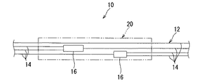
以下、第1実施形態に係るワイヤーハーネス及び保護部材について説明する。図1は第1実施形態に係るワイヤーハーネス10を示す概略部分斜視図である。
{First embodiment}
Hereinafter, the wire harness and the protection member according to the first embodiment will be described. FIG. 1 is a schematic partial perspective view showing the
このワイヤーハーネス10は、ワイヤーハーネス本体12と、保護部材20とを備える。
The
ワイヤーハーネス本体12は、少なくとも1本の電線を含む。ここでは、ワイヤーハーネス本体12は、複数の電線が束ねられた部分を含んでおり、この部分が保護部材20によって保護される。ワイヤーハーネス本体12は途中で分岐していてもよい。ワイヤーハーネス本体12には、光ファイバケーブル等が含まれていてもよい。保護部材によるワイヤーハーネス本体の保護部分は、ワイヤーハーネス本体の一部であってもよいし、全部であってもよい。
The
上記ワイヤーハーネス本体12は、車両における所定の配線形態に沿って配設された状態で、コネクタ接続等を介して各種車載電気部品に接続される。これにより、車載電気部品がワイヤーハーネス本体12を介して相互に電気的に接続される。つまり、ワイヤーハーネス本体12は、車両における配線材として用いられる。
The said wire harness
保護部材20は、不織部材22と防水シート24とが重ね合された状態でホットプレスされることにより、ワイヤーハーネス本体12を覆う形状に形成されている。ここでは、不織部材22と防水シート24とが重ね合された状態で、その重ね合せ体がその両面側から所定形状のホットプレス用の成形型によって加圧されることにより、ワイヤーハーネス本体12を収容可能な形状の保護部材20が形成されている。
The
ここで、ホットプレスとは、不織部材に対して加熱処理及び不織部材を型に押付けて所定形状に形成する処理を施すことをいう。加熱処理と所定形状への形成処理とは、同時に行われてもよいし、或は、連続的に別々に行われてもよい。例えば、不織部材を加熱した後、冷却により固まる前に所定の成形型に押付けることで、当該成形型に応じた形状に維持できる。本実施形態に係る保護部材20を加工するのに適したホットプレス加工の例については後にさらに詳述する。
Here, the hot press refers to performing a heat treatment on a non-woven member and a process of pressing the non-woven member against a mold to form a predetermined shape. The heat treatment and the forming process into a predetermined shape may be performed simultaneously, or may be performed separately continuously. For example, after heating a non-woven member, it can be maintained in the shape according to the said shaping | molding die by pressing against a predetermined shaping | molding die before hardening by cooling. An example of hot pressing suitable for processing the
また、加工対象となる不織部材としては、少なくとも一部が溶融し或いは軟らかくなり、その後冷却工程を経て硬くなることが可能なものを用いることができる。このような不織部材として、基本繊維とバインダ(接着樹脂とも呼ばれる)とを含むものを用いることができる。バインダは、基本繊維の融点よりも低い融点を有する樹脂である。そして、不織部材を、基本繊維の融点より低く且つバインダの融点よりも高い温度に加熱することにより、バインダが溶融されて基本繊維間にしみ込む。この後、不織部材の温度が低下すると、バインダが凝固する。これにより、不織部材を加熱時の成形状態に維持することができる。また、凝固したバインダは、不織部材同士の接触箇所を接合することもできる。さらに、溶融して凝固した樹脂は、不織部材と当該不織部材に接触する防水シートとを接合することもできる。 In addition, as the non-woven member to be processed, one that can be at least partially melted or softened and then hardened through a cooling step can be used. As such a non-woven member, a material containing basic fibers and a binder (also called an adhesive resin) can be used. The binder is a resin having a melting point lower than that of the basic fiber. Then, by heating the nonwoven member to a temperature lower than the melting point of the basic fiber and higher than the melting point of the binder, the binder is melted and soaks between the basic fibers. Thereafter, when the temperature of the nonwoven member is lowered, the binder is solidified. Thereby, a nonwoven member can be maintained in the shaping | molding state at the time of a heating. Moreover, the solidified binder can also join the contact location of nonwoven members. Furthermore, the molten and solidified resin can also join the nonwoven member and the waterproof sheet in contact with the nonwoven member.
不織部材の基本繊維としては、バインダの融点で繊維状態を保ち得るものであればよく、樹脂繊維の他、ガラス繊維等の各種繊維を用いることができる。また、バインダは、基本繊維の融点より低い融点を有する熱可塑性樹脂繊維を用いることができる。バインダは、基本繊維を覆う状態で存在していてもよいし、繊維状又は粒状の状態で存在していてもよい。基本繊維とバインダとの組合せとしては、例えば、基本繊維をPET(ポリエチレンテレフタレート)の樹脂繊維とし、バインダをPETとPEI(ポリエチレンイソフタレート)との共重合樹脂としたものが挙げられる。 As a basic fiber of a nonwoven member, what is necessary is just to be able to maintain a fiber state with melting | fusing point of a binder, and various fibers, such as glass fiber other than a resin fiber, can be used. Moreover, the thermoplastic resin fiber which has melting | fusing point lower than melting | fusing point of a basic fiber can be used for a binder. The binder may be present in a state of covering the basic fiber, or may be present in a fibrous or granular state. Examples of the combination of the basic fiber and the binder include those in which the basic fiber is a resin fiber of PET (polyethylene terephthalate) and the binder is a copolymer resin of PET and PEI (polyethylene isophthalate).
また、ここでは、保護部材20は、ワイヤーハーネス本体12の少なくとも一部を覆う形状として、筒状に形成されている。ここでは、保護部材20は、直線状に延在しているが、途中で曲っていてもよいし、また、途中で分岐していてもよい。
Here, the
より具体的には、保護部材20は、収容本体部26と、蓋部28とを備える。収容本体部26及び蓋部28のそれぞれは、不織部材22と防水シート24とが重ね合された状態で、その重ね合せ体がその両面側から所定形状のホットプレス用の成形型によって加圧されることにより、所定形状に形成されている。そして、収容本体部26及び蓋部28が全体としてワイヤーハーネス本体12を収容可能な所定形状に形成されている。
More specifically, the
収容本体部26は、半筒状部26aと、一対の側片部26bとを備える。
The housing
半筒状部26aは、一側方(図1では上方)が開口する半筒状に形成されている。半筒状部26aの軸方向に対して直交する断面形状は、U字状をなしている。この半筒状部26a内にワイヤーハーネス本体12の全体を収容できるようになっている。
The
一対の側片部26bは、半筒状部26aの両側部から外方に延出する細長平板状の片に形成されている。
The pair of
収容本体部26は、外周側の不織部材22と内周側の防水シート24との2層構造とされている。防水シート24は、不織部材22をホットプレスする際に、不織部材22のバインダによって当該不織部材22に接合されている。防水シート24としては、ポリ塩化ビニルシート(PVCシート)等を用いることができ、好ましくは、バインダの融点よりも高い融点(例えば、120度以上)を持つ防水シート(耐熱PVCシート等)を用いることが好ましい。
The
蓋部28は、上記半筒状部26aの開口を閉塞可能な板状、より具体的には、長方形板状に形成されている。蓋部28も、上記収容本体部26と同様に、外側の不織部材22と内側の防水シート24との2層構造とされている。
The
そして、収容本体部26の半筒状部26a内にワイヤーハーネス本体12を収容した状態で、一対の側片部26bと蓋部28の両側部とを突合わせるようにして、それらを接合することによって、ワイヤーハーネス本体12が保護部材20によって覆われたワイヤーハーネス10を得ることができる。この状態では、保護部材20の最内層に、防水シート24が設けられる。
And in the state which accommodated the wire harness
なお、一対の側片部26bと蓋部28との接合は、接着剤、粘着剤、両面テープ、超音波接合、加熱接合等の各種接合構成を採用することができる。
In addition, various joining structures, such as an adhesive agent, an adhesive, a double-sided tape, ultrasonic joining, and heat joining, are employable for joining a pair of
なお、保護部材20が上記形状に形成されていることは必須ではない。例えば、保護部材は、全体として角筒状をなす形状に形成されていてもよい。また、2つの半筒状部分が組合わされて、1つの筒状の保護部材を形成する構成であってもよい。また、保護部材を構成する複数の部分がヒンジ部を介して開閉可能に連結されていてもよい。また、保護部材がワイヤーハーネス本体の周方向全体を覆うことは必須ではなく、その周方向の一部のみを覆う形状であってもよい。
In addition, it is not essential that the
上記のような保護部材20では、不織部材22によって所定形状を保ち、防水シート24によって外周から内周への水の浸透を抑制することができる。このため、ワイヤーハーネス本体12に対する水の付着を有効に抑制することができる。なお、本実施形態では、防水シート24が保護部材20の最内周に設けられている例で説明するが、防水シートは保護部材の厚み方向中間層又は最外層に設けられていてもよい。特に、防水シートは保護部材の厚み方向中間層に設けられている例については、後で変形例として説明する。
In the
このような保護部材20は、例えば、図2及び図3に示すように、ワイヤーハーネス本体12がスプライス部16を含む場合において、当該スプライス部16を覆うように設けられる場合に有効な構成である。
For example, as shown in FIGS. 2 and 3, such a
すなわち、スプライス部16では、電線14の長手方向中間部又は端部において芯線15が露出され、露出された芯線15同士が超音波接合、半田付、スプライス端子等によって接続された構成とされている。かかるスプライス部16は、通常、シリコーン、樹脂シート、熱収縮チューブ等の封止部材17によって封止されるものの、より完全に水等から封止されることが好ましい。そこで、ワイヤーハーネス本体12のうちスプライス部16を含む部分を、上記保護部材20で覆うことにより、防水シート24によって、スプライス部16をより確実に水等から封止することができる。
That is, the
特に、ワイヤーハーネス本体12のうち保護部材20によって覆われる部分に複数のスプライス部16が存在する場合(図2参照)、それらの複数のスプライス部16間に水が付着すると、両者間の電位差等によって電食が発生する恐れがある。
In particular, when a plurality of
そこで、ワイヤーハーネス本体12のうち複数のスプライス部16が設けられた部分を、防水シート24を備える1つの保護部材20で覆うことによって、複数のスプライス部16間の水の付着を抑制して、電食を有効に抑制することができる。これにより、スプライス部16の位置、数等による制約を少なくして、不織部材22によって形成された保護部材20によって、ワイヤーハーネス本体12を覆うことができる。
Therefore, by covering the portion of the
上記保護部材20の製造方法例について説明する。
An example of a method for manufacturing the
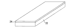
まず、図4に示すように、不織部材22と防水シート24とを重ね合せる。なお、不織部材22及び防水シート24は、ホットプレスした状態で、上記収容本体部26又は蓋部28を形成可能な所定の方形状に事前に切断されていることが好ましい。
First, as shown in FIG. 4, the
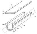
そして、図5に示すように、不織部材22と防水シート24との重ね合せ体を、ホットプレス用の成形型50を用いてホットプレスし、収容本体部26を成型する。
Then, as shown in FIG. 5, the stacked body of the
この成形型50は、下型52と、上型62とを備える。
The
下型52は、熱伝導性に優れた金属等により形成された長尺部材であり、その一主面(上面)に下型面53が形成されている。下型面53は、収容本体部26の外周表面を形成する部分であり、横断面U字状をなす溝の両側部が一段凹む形状を呈する溝形状に形成されている。下型面53の延在方向の寸法は、ワイヤーハーネス本体12のうち保護対象部分となる部分の長さ寸法と同一かそれよりも長い程度に設定されている。下型面53は、ワイヤーハーネス本体12における保護対象部分を車体に配設した場合の経路に応じて延びる形状に形成されている。
The
上型62は、熱伝導性に優れた金属等により形成された長尺部材であり、その一主面(下面)に上型面63が形成されている。上型面63は、収容本体部26の内周表面を形成する部分であり、横断面U字状をなす細長突起部分の両側部に外方に向かう平面が形成された形状に形成されている。上型面63の細長突起部分は、上記上型面63内に配設可能な大きさに設定されている。
The
そして、この上型面63が下型面53上に配設されることにより、それらの間で、収容本体部26を形成可能なスペースが形成される。なお、下型52及び上型62には、ヒーター等の加熱部54、64が設けられている。
The
上記ホットプレス用の成形型50を用いてホットプレス加工を行う方法について説明する。
A method of performing hot pressing using the hot
まず、不織部材22と防水シート24との重ね合せ体を、下型面53内に配設する。なお、下型面53上で、不織部材22と防水シート24との重ね合せ作業を行ってもよい。
First, a laminated body of the
この後、上型62の上型面63を下型面53上に配設し、下型面53及び上型面63によって上記重ね合せ体をその両面側から挟込む。すると、重ね合せ体が下型52及び上型62に接触する部分を中心として加熱される。
Thereafter, the
この後、重ね合せ体が冷却されると、上記下型52及び上型62間で、不織部材22が下型面53の形状に応じた形状で硬化する。また、不織部材22と防水シート24とは、不織部材22のバインダ樹脂によって重ね合せ状態に接合される。これにより、収容本体部26が形成される。
Thereafter, when the overlapped body is cooled, the
蓋部28についても、当該蓋部28の形状に応じた形状のホットプレス用の成形型によって、上記と同様にして製造される。
The
そして、図6に示すように、収容本体部26内にワイヤーハーネス本体12を収容し、収容本体部26と蓋部28とを合体させる。両者の合体は、上記したように、一対の側片部26bと蓋部28の側部とを接着剤、粘着剤、両面テープ等で接合すること等により行うことができる。
And as shown in FIG. 6, the wire harness
以上のように構成されたワイヤーハーネス10及び保護部材20によると、保護部材20は、不織部材22と防水シート24とが重ね合された状態でホットプレスされることにより、ワイヤーハーネス本体12を覆う形状に形成されているため、防水シート24によって水の浸透を有効に抑制することができる。
According to the
また、ホットプレスの際に、不織部材22と防水シート24とが接合されるため、その一体化形態を容易に製造することができる。
Moreover, since the
また、防水シート24が保護部材20の厚み方向の最内層に設けられているため、保護部材20の外周を柔らかい状態に保つことができる。これにより、保護部材20とその周辺部材との接触による音の発生を有効に抑制することができる。
Moreover, since the
また、最内周に防水シート24が設けられているため、いずれかの不織部材22が保護部材20の端部からの水又は空気中の水分を吸収し湿気ってしまったような場合でも、当該水分を吸収した不織部材22が直接ワイヤーハーネス本体12に触れることが抑制され、ワイヤーハーネス本体12に対する水の付着を有効に抑制することができる。
Further, since the
なお、図7に示す変形例に係るワイヤーハーネス10Bのように、保護部材20Bの厚み方向中間層に、防水シート24Bが設けられていてもよい。この保護部材20Bの収容本体部26B及び蓋部28Bは、例えば、2枚の不織部材22Bの間に防水シート24Bを挟込むようにそれらを重ね合せ、それらの重ね合せ体を上記と同様にホットプレスすることによって製造することができる。
In addition, the
この変形例によると、最内周に防水シート24が設けられていることによる作用効果を除いて、上記実施形態と同様の作用効果を得ることができる。加えて、保護部材20Bの内部で不織部材22Bが露出しているため、保護部材20Bの内面とワイヤーハーネス本体12との接触による音の発生をも有効に抑制することができるという利点がある。また、最外周の不織部材22が湿気ってしまったような場合でも、その内側の中間層の防水シート24によって、当該水分がワイヤーハーネス本体12側に浸透することを有効に抑制することができる。
According to this modified example, the same operational effects as those of the above embodiment can be obtained except for the operational effects due to the provision of the
また、保護部材20は、不織部材22と防水シート24とが重ね合された状態で、その両面側から成形型50によって加圧されることにより、ワイヤーハーネス本体12を収容可能な所定形状に形成されるため、予め保護部材20を形成しておき、この保護部材20によってワイヤーハーネス本体12を覆うことができる。これにより、保護部材20の効率的な生産が可能となり、また、ワイヤーハーネス組立図板の簡素化及びワイヤーハーネス組立図板上での作業の簡素化等が可能となる。
Moreover, the
{第2実施形態}
第2実施形態に係るワイヤーハーネス110について説明する。図8は、第2実施形態に係るワイヤーハーネス110を示す概略部分斜視図である。
{Second Embodiment}
A
このワイヤーハーネス110は、ワイヤーハーネス本体12と、保護部材120とを備える。
The
ワイヤーハーネス本体12は、上記第1実施形態で説明したものと同様であるため、ここでは、重複説明を省略する。
Since the wire harness
保護部材120は、上記不織部材22と同様の不織部材122と、上記防水シート24と同様の防水シート124とが重ね合された状態でホットプレスされることにより、ワイヤーハーネス本体12を覆う形状に形成されている、という点では、上記保護部材20と同様部材である。
The
本保護部材120が上記保護部材20と異なる点は、本保護部材120は、不織部材122と防水シート124とをワイヤーハーネス本体12に巻付けた状態で、その外周側から成形型によって加圧されることにより形成されている点である。
The present
すなわち、保護部材120は、ワイヤーハーネス本体12を覆う筒形状(ここでは円筒形状)に形成されている。保護部材120の内周部は、ワイヤーハーネス本体12の外周形状(つまり、電線束の外周がなす形状)に応じた凹凸形状に形成されている。また、保護部材120の外周部は、後述する成形型150によって形作られた所定形状をなしている。
That is, the
上記保護部材120は例えば次のようにして形成される。
The
図9は、上記保護部材120の形成工程を示す説明図である。同図に示すように、保護部材20を形成するためのホットプレス用の成形型150は、下型152と、上型162とを備える。
FIG. 9 is an explanatory view showing a process of forming the
下型152は、熱伝導性に優れた金属等により形成された長尺部材であり、その一主面(上面)に下型面153が形成されている。下型面153は、保護部材120の外周表面の一部(下半部分)を形成する部分であり、上方に開口する横断面U字状をなす溝形状に形成されている。下型面153の延在方向の寸法は、ワイヤーハーネス本体12のうち保護対象部分となる部分の長さ寸法と同一かそれよりも長い程度に設定されている。下型面153は、ワイヤーハーネス本体12における保護対象部分を車体に配設した場合の経路に応じて延びる形状に形成されている。
The
上型162は、熱伝導性に優れた金属等により形成された長尺部材であり、その一主面(下面)に上型面163が形成されている。上型面163は、保護部材120の外周表面の一部(上半部分)を形成する部分であり、下方に開口する横断面半円弧状をなす溝形状に形成されている。
The
そして、この上型面163が下型面153上に配設されることにより、それらの間で、保護部材120を形成可能な円柱状のスペースが形成される。なお、下型152及び上型162には、ヒーター等の加熱部が設けられている。
The
そして、防水シート124と不織部材122との重ね合せ体をワイヤーハーネス本体12に巻付ける。ここでは、防水シート124が最内周に配設されるように、重ね合せ体をワイヤーハーネス本体12に巻付けている。防水シートは最外層に配設されてもよいし、また、防水シートが不織部材間に挟み込まれ、保護部材の中間層に配設されてもよい。また、防水シートと不織部材とを順次ワイヤーハーネス本体12に巻付け、当該巻付状態で、防水シートと不織部材とが重ね合されてもよい。
Then, an overlapped body of the
この後、ワイヤーハーネス本体12に上記重ね合せ体が巻付けられたものを、下型面153内に配設する。
Thereafter, the
この後、上型162の上型面163を下型面153上に配設し、下型面153及び上型面163によって上記重ね合せ体を上下から挟込む。すると、重ね合せ体が下型152及び上型162に接触する部分を中心として加熱される。
Thereafter, the
この後、重ね合せ体が冷却されると、上記下型152及び上型162間で、不織部材122の外周面が下型面153及び上型面163の形状に応じた形状、ここでは、円柱周面形状に硬化し、上記ワイヤーハーネス本体12に巻付けられた形状に維持される。また、不織部材22と防水シート24とは、不織部材22のバインダ樹脂によって重ね合せ状態に接合され、これによっても、巻付状態が維持され、上記保護部材120が形成される。
Thereafter, when the stacked body is cooled, the outer peripheral surface of the
これにより、ワイヤーハーネス110が製造される。
Thereby, the
このように構成されたワイヤーハーネス110によると、不織部材と防水シートとが重ね合された状態で、その両面側から成形型によって加圧されることによって、ワイヤーハーネス本体を収容可能な形状に形成されることによる作用効果を除いて、上記第1実施形態と同様の作用効果を得ることができる。
According to the
加えて、本実施形態では、保護部材120は、不織部材122と防水シート124とがワイヤーハーネス本体12に巻付けられた状態で、それらの外周側から成形型150によって加圧されることにより形成されるため、ワイヤーハーネス本体12の形状にぴったりと適合したワイヤーハーネス110を製造することができ、そのコンパクト化等が可能となる。
In addition, in this embodiment, the
{変形例}
なお、上記各実施形態では、保護部材20、20B、120の長手方向全体に防水シート24、24B、124が設けられている例で説明したが、保護部材の長手方向の少なくとも一部に防水シートが設けられていればよい。なお、ワイヤーハーネス本体にスプライス部が設けられている場合には、当該スプライス部を覆う部分に、防水シートが設けられていることが好ましい。
{Modification}
In each of the above embodiments, the
なお、上記各実施形態及び変形例で説明した各構成は、相互に矛盾しない限り適宜組合わせることができる。例えば、第2実施形態において、防水シートが保護部材20の厚み方向中間層又は最外層に設けられていてもよい。
In addition, each structure demonstrated by each said embodiment and modification can be suitably combined unless it mutually contradicts. For example, in 2nd Embodiment, the waterproof sheet may be provided in the thickness direction intermediate | middle layer or outermost layer of the
以上のようにこの発明は詳細に説明されたが、上記した説明は、すべての局面において、例示であって、この発明がそれに限定されるものではない。例示されていない無数の変形例が、この発明の範囲から外れることなく想定され得るものと解される。 As described above, the present invention has been described in detail. However, the above description is illustrative in all aspects, and the present invention is not limited thereto. It is understood that countless variations that are not illustrated can be envisaged without departing from the scope of the present invention.
10、10B、110 ワイヤーハーネス
12 ワイヤーハーネス本体
16 スプライス部
20、20B、120 保護部材
22、22B、122 不織部材
24、24B、124 防水シート
50、150 成形型
152、152 下型
153、153 下型面
162、162 上型
163、163 上型面
10, 10B, 110
Claims (5)
不織部材と防水シートとが重ね合された状態でホットプレスされることにより、前記ワイヤーハーネス本体を覆う形状に形成された保護部材と、
を備え、
前記保護部材は、それぞれ前記不織部材と前記防水シートとを含む複数層構造とされた収容本体部と蓋部とを備え、
前記収容本体部は、前記ワイヤーハーネス本体の全体を収容可能な半筒状部と、前記半筒状部の両側部から外方に延出する細長平板状の一対の側片部とを備え、
前記蓋部は、前記半筒状部の開口を閉塞可能な長方形板状に形成されており、
前記収容本体部の前記半筒状部内に前記ワイヤーハーネス本体を収容した状態で、前記一対の側片部と前記蓋部の両側部とが接合されることにより、前記ワイヤーハーネス本体が前記保護部材によって覆われた状態とされている、ワイヤーハーネス。 A wire harness body,
A protective member formed in a shape covering the wire harness body by being hot pressed in a state where the nonwoven member and the waterproof sheet are overlapped,
Equipped with a,
The protective member includes an accommodating main body portion and a lid portion each having a multi-layer structure including the nonwoven member and the waterproof sheet,
The accommodating main body includes a semi-cylindrical portion that can accommodate the entire wire harness main body, and a pair of elongated flat plate-like side pieces extending outward from both side portions of the semi-cylindrical portion,
The lid is formed in a rectangular plate shape capable of closing the opening of the semi-cylindrical part,
In a state where the wire harness body is housed in the semi-cylindrical part of the housing body part, the pair of side piece parts and both side parts of the lid part are joined, so that the wire harness body is the protective member. A wire harness that is covered by the wire harness.
前記防水シートは、前記保護部材の厚み方向中間層又は最内層に設けられている、ワイヤーハーネス。 The wire harness according to claim 1,
The said waterproof sheet is a wire harness provided in the thickness direction intermediate | middle layer or innermost layer of the said protection member.
前記ワイヤーハーネス本体は、電線の芯線同士が接続されたスプライス部を含み、
前記保護部材は、前記スプライス部を覆うように設けられている、ワイヤーハーネス。 The wire harness according to claim 1 or claim 2,
The wire harness body includes a splice part in which core wires of electric wires are connected to each other,
The said protection member is a wire harness provided so that the said splice part may be covered.
前記保護部材の前記収容本体部と前記蓋部とは、前記不織部材と前記防水シートとが重ね合された状態とされかつ前記ワイヤーハーネス本体と組み合わせる前の重ね合せ体が、その両面側から成形型によって加圧されることにより、全体として前記ワイヤーハーネス本体を収容可能な形状に形成されたものである、ワイヤーハーネス。 It is a wire harness as described in any one of Claims 1-3,
The accommodation body portion and the lid portion of the protection member are in a state where the nonwoven member and the waterproof sheet are overlapped and the overlapped body before being combined with the wire harness body is from both sides thereof A wire harness that is formed into a shape capable of accommodating the wire harness body as a whole by being pressurized by a molding die.
不織部材と防水シートとが重ね合された状態とされかつ前記ワイヤーハーネス本体と組み合わせる前の重ね合せ体が、その両面側から成形型によって加圧されることにより、全体として前記ワイヤーハーネス本体を収容可能な形状に形成されており、
それぞれ前記不織部材と前記防水シートとを含む複数層構造とされた収容本体部と蓋部とを備え、
前記収容本体部は、前記ワイヤーハーネス本体の全体を収容可能な半筒状部と、前記半筒状部の両側部から外方に延出する細長平板状の一対の側片部とを備え、
前記蓋部は、前記半筒状部の開口を閉塞可能な長方形板状に形成されており、
前記収容本体部の前記半筒状部内に前記ワイヤーハーネス本体を収容した状態で、前記一対の側片部と前記蓋部の両側部とが接合されることにより、前記ワイヤーハーネス本体を覆うことが可能な形状に形成されている、保護部材。 A protective member covering the wire harness body,
When the non-woven member and the waterproof sheet are overlapped and the overlapped body before being combined with the wire harness body is pressed by the molding die from both sides, the wire harness body as a whole is It is formed in a shape that can be accommodated ,
Each of the main body and the lid is a multi-layer structure including the nonwoven member and the waterproof sheet,
The accommodating main body includes a semi-cylindrical portion that can accommodate the entire wire harness main body, and a pair of elongated flat plate-like side pieces extending outward from both side portions of the semi-cylindrical portion,
The lid is formed in a rectangular plate shape capable of closing the opening of the semi-cylindrical part,
Covering the wire harness body by joining the pair of side pieces and both sides of the lid in a state where the wire harness body is housed in the semi-cylindrical part of the housing body. A protective member formed in a possible shape .
Priority Applications (2)
| Application Number | Priority Date | Filing Date | Title |
|---|---|---|---|
| JP2013217641A JP6119552B2 (en) | 2013-10-18 | 2013-10-18 | Wire harness and protective member |
| PCT/JP2014/076010 WO2015056561A1 (en) | 2013-10-18 | 2014-09-30 | Wire harness and protective member |
Applications Claiming Priority (1)
| Application Number | Priority Date | Filing Date | Title |
|---|---|---|---|
| JP2013217641A JP6119552B2 (en) | 2013-10-18 | 2013-10-18 | Wire harness and protective member |
Publications (2)
| Publication Number | Publication Date |
|---|---|
| JP2015080380A JP2015080380A (en) | 2015-04-23 |
| JP6119552B2 true JP6119552B2 (en) | 2017-04-26 |
Family
ID=52828009
Family Applications (1)
| Application Number | Title | Priority Date | Filing Date |
|---|---|---|---|
| JP2013217641A Expired - Fee Related JP6119552B2 (en) | 2013-10-18 | 2013-10-18 | Wire harness and protective member |
Country Status (2)
| Country | Link |
|---|---|
| JP (1) | JP6119552B2 (en) |
| WO (1) | WO2015056561A1 (en) |
Families Citing this family (4)
| Publication number | Priority date | Publication date | Assignee | Title |
|---|---|---|---|---|
| CN106043162B (en) * | 2016-06-12 | 2018-08-10 | 奇瑞汽车股份有限公司 | A kind of reinforcement turnup structure of metal plate holder |
| JP2019160568A (en) | 2018-03-13 | 2019-09-19 | 矢崎総業株式会社 | Wire harness, and manufacturing method of sheet material with wire harness |
| CN109301776B (en) * | 2018-11-13 | 2020-06-02 | 六安市匠心信息科技有限公司 | Bridge capable of preventing water from accumulating at bottom |
| JP7779875B2 (en) * | 2023-04-25 | 2025-12-03 | 矢崎総業株式会社 | Wire harness and method for manufacturing wire harness |
Family Cites Families (5)
| Publication number | Priority date | Publication date | Assignee | Title |
|---|---|---|---|---|
| JP2000125437A (en) * | 1998-10-16 | 2000-04-28 | Sumitomo Wiring Syst Ltd | Armor structure for wire harness |
| JP5353801B2 (en) * | 2010-04-09 | 2013-11-27 | 住友電装株式会社 | Electric wire protector |
| US20130020125A1 (en) * | 2010-04-28 | 2013-01-24 | Sumitomo Wiring Systems, Ltd. | Wire harness, wire harness manufacturing method |
| JP5353814B2 (en) * | 2010-05-19 | 2013-11-27 | 住友電装株式会社 | Wire harness protection structure |
| JP2012005165A (en) * | 2010-06-14 | 2012-01-05 | Sumitomo Wiring Syst Ltd | Electric wire protection tool with long object fixing part |
-
2013
- 2013-10-18 JP JP2013217641A patent/JP6119552B2/en not_active Expired - Fee Related
-
2014
- 2014-09-30 WO PCT/JP2014/076010 patent/WO2015056561A1/en not_active Ceased
Also Published As
| Publication number | Publication date |
|---|---|
| WO2015056561A1 (en) | 2015-04-23 |
| JP2015080380A (en) | 2015-04-23 |
Similar Documents
| Publication | Publication Date | Title |
|---|---|---|
| JP6798471B2 (en) | How to manufacture wire harnesses and wire harnesses | |
| US9511724B2 (en) | Wire harness | |
| JP6119552B2 (en) | Wire harness and protective member | |
| WO2012020596A1 (en) | Electric wire protection structure and method for manufacturing electric wire protection structure | |
| CN103890861B (en) | The manufacture method of wire harness and wire harness | |
| JP6579227B1 (en) | Wiring member | |
| KR20130072118A (en) | Wire harness | |
| JP5884620B2 (en) | Wire harness, method for manufacturing wire harness, and protective member | |
| JP2014068458A (en) | Wire harness, method for manufacturing wire harness and protective member | |
| WO2018235788A1 (en) | Wire harness and method of manufacturing wire harness | |
| WO2011102013A1 (en) | Wire with protection member and method of manufacturing same | |
| JP5884695B2 (en) | Wire harness, method for manufacturing wire harness, and protective member | |
| EP2741299B1 (en) | Wire harness | |
| JP5939098B2 (en) | Wire harness | |
| CN107408424B (en) | External wire harness | |
| US20140102747A1 (en) | Wire harness | |
| JP2012146500A (en) | Wire harness, manufacturing method for covering member and manufacturing method for wire harness | |
| WO2014083891A1 (en) | Wire harness | |
| WO2013046769A1 (en) | Wire harness production method and wire harness | |
| JP5803735B2 (en) | Wire harness and method for manufacturing wire harness | |
| JP5556606B2 (en) | Wire bundle with covering member and method of manufacturing wire bundle with covering member | |
| JP2013058438A (en) | Wire harness and manufacturing method of the same | |
| CN113168938B (en) | Wiring components | |
| JP2013236469A (en) | Wire harness | |
| JP2026002372A (en) | Wiring materials |
Legal Events
| Date | Code | Title | Description |
|---|---|---|---|
| A621 | Written request for application examination |
Free format text: JAPANESE INTERMEDIATE CODE: A621 Effective date: 20151224 |
|
| A131 | Notification of reasons for refusal |
Free format text: JAPANESE INTERMEDIATE CODE: A131 Effective date: 20161213 |
|
| A521 | Request for written amendment filed |
Free format text: JAPANESE INTERMEDIATE CODE: A523 Effective date: 20170210 |
|
| TRDD | Decision of grant or rejection written | ||
| A01 | Written decision to grant a patent or to grant a registration (utility model) |
Free format text: JAPANESE INTERMEDIATE CODE: A01 Effective date: 20170228 |
|
| A61 | First payment of annual fees (during grant procedure) |
Free format text: JAPANESE INTERMEDIATE CODE: A61 Effective date: 20170313 |
|
| R150 | Certificate of patent or registration of utility model |
Ref document number: 6119552 Country of ref document: JP Free format text: JAPANESE INTERMEDIATE CODE: R150 |
|
| LAPS | Cancellation because of no payment of annual fees |