JP6115205B2 - Bending vibration piece, method for manufacturing bending vibration piece, vibration device, electronic apparatus, and moving body - Google Patents
Bending vibration piece, method for manufacturing bending vibration piece, vibration device, electronic apparatus, and moving body Download PDFInfo
- Publication number
- JP6115205B2 JP6115205B2 JP2013050101A JP2013050101A JP6115205B2 JP 6115205 B2 JP6115205 B2 JP 6115205B2 JP 2013050101 A JP2013050101 A JP 2013050101A JP 2013050101 A JP2013050101 A JP 2013050101A JP 6115205 B2 JP6115205 B2 JP 6115205B2
- Authority
- JP
- Japan
- Prior art keywords
- arm
- base
- bending vibration
- vibration piece
- width
- Prior art date
- Legal status (The legal status is an assumption and is not a legal conclusion. Google has not performed a legal analysis and makes no representation as to the accuracy of the status listed.)
- Active
Links
Images


Landscapes
- Oscillators With Electromechanical Resonators (AREA)
- Piezo-Electric Or Mechanical Vibrators, Or Delay Or Filter Circuits (AREA)
Description
本発明は、一対の振動腕を備えた屈曲振動片、並びに、この屈曲振動片の製造方法、およびこの屈曲振動片を備えた振動デバイス、電子機器、および移動体に関する。 The present invention relates to a bending vibration piece including a pair of vibrating arms, a method for manufacturing the bending vibration piece, and a vibration device, an electronic apparatus, and a moving body including the bending vibration piece.
コンピュータや携帯電話、小型情報機器等のクロック信号源として用いられている屈曲振動片には、種々の形態のものが知られている。中でも、音叉型の屈曲振動片は、振動部と支持部との形態が異なるため、振動漏れの影響を受け難く、比較的小型化し易いという特徴がある。 Various types of flexural vibration pieces used as clock signal sources for computers, mobile phones, small information devices, and the like are known. Among them, the tuning fork-type bending vibration piece is characterized in that it is not easily affected by vibration leakage and is relatively easy to downsize because the form of the vibration part and the support part are different.
しかし、近年における強い小型化傾向は、上記のような特徴を持つ音叉型屈曲振動片であっても、振動漏れへの対策を採らなければ、所望される特性を得ることができない。このような実状の中、小型化、高性能化に適した音叉型屈曲振動片の形態として、特許文献1に開示されているようなものが知られている。特許文献1に開示されている屈曲振動片は、基部の一端から延出された2つの振動腕の間に支持腕を設け、この支持腕に、接続用の電極パッドを配置する構成を基本としたものである。このような構成とすることで、振動腕と支持部となる電極パッドまでの距離が遠くなり、振動漏れを抑制することができる。なお、特許文献1に開示されている屈曲振動片ではさらに、振動腕に、その幅方向全幅に渡る溝を形成することで、振動漏れの発生を抑制する旨が記載されている。 However, due to the recent strong trend toward miniaturization, even the tuning fork-type bending vibration piece having the above-described characteristics cannot obtain desired characteristics unless measures are taken against vibration leakage. Among such actual situations, a tuning fork-type bending vibration piece suitable for downsizing and high performance is disclosed in Patent Document 1. The flexural vibration piece disclosed in Patent Document 1 is basically based on a configuration in which a support arm is provided between two vibration arms extending from one end of a base, and an electrode pad for connection is disposed on the support arm. It is a thing. By setting it as such a structure, the distance to the electrode pad used as a vibrating arm and a support part becomes long, and a vibration leak can be suppressed. In addition, the bending vibration piece disclosed in Patent Document 1 further describes that a vibration arm is formed with a groove extending over the entire width in the width direction to suppress the occurrence of vibration leakage.
振動腕の間に支持腕を設ける構成の屈曲振動片では、製造工程においては、支持腕の先端側に、ウエハー側支持部との連結部が設けられる。屈曲振動片の製造工程では、屈曲振動片を個片化する前に、ウエハー状態における周波数特性の検査が行われる。このため、連結部を支持腕の先端側とすることで、ウエハー状態における周波数特性検査時と、個片化された後の支持部の位置とが近似することとなり、支持位置の変化に起因する周波数特性の変化が小さいという利点がある。 In a bending vibration piece having a configuration in which a support arm is provided between vibration arms, a connecting portion with a wafer-side support portion is provided on the distal end side of the support arm in the manufacturing process. In the manufacturing process of the bending vibration piece, the frequency characteristic in the wafer state is inspected before the bending vibration piece is separated. For this reason, by setting the connecting portion to the tip side of the support arm, the frequency characteristic inspection in the wafer state and the position of the support portion after being separated into pieces are approximated, resulting in a change in the support position. There is an advantage that a change in frequency characteristics is small.
また、支持腕の先端に連結部を配置することで、1つの屈曲振動片がウエハー中に占めるスペースに無駄が無く、量産性にも優れることとなる。 Further, by arranging the connecting portion at the tip of the support arm, the space occupied by one flexural vibration piece in the wafer is not wasted and the mass productivity is excellent.
しかし、特許文献1に開示されているような構成の屈曲振動片では、屈曲振動片がさらに小型化された際には、屈曲振動周波数を所定の周波数(例えば32.768kHz)に維持するために、振動腕先端側の質量を増加させる必要が生じる。このような課題は、振動腕の先端側の幅が広い、いわゆるハンマーヘッド型とすることで解決することができる。 However, in the bending vibration piece configured as disclosed in Patent Document 1, when the bending vibration piece is further downsized, the bending vibration frequency is maintained at a predetermined frequency (for example, 32.768 kHz). Therefore, it is necessary to increase the mass on the tip side of the vibrating arm. Such a problem can be solved by using a so-called hammer head type in which the width of the tip side of the vibrating arm is wide.
ところが、振動腕の形態をハンマーヘッド型とした場合、屈曲振動片を所望の大きさで実現しようとすると、2本の振動腕のハンマーヘッドの間、すなわち支持腕の先端側に確保されていたスペースをそれまで以上に狭くせざるを得ない。このため、支持腕の先端側に、ウエハー側支持部との連結部を設けてしまうと、連結部に衝撃に耐え得るだけの十分な強度をもたせることが困難となってしまう。 However, when the form of the vibrating arm is a hammer head type, if the bending vibrating piece is to be realized in a desired size, it is secured between the hammer heads of the two vibrating arms, that is, on the tip side of the support arm. I have to make the space narrower than before. For this reason, if a connection portion with the wafer side support portion is provided on the distal end side of the support arm, it becomes difficult to give the connection portion sufficient strength to withstand an impact.
そこで本発明では、支持腕に連結部を設けることができない場合であっても、対を成す振動腕の間に支持腕を配置することが可能で、生産性が良好な屈曲振動片を提供することを第1の目的とする。また、本発明では、基部に連結部を設ける屈曲振動片の製造方法を提供することを第2の目的とする。さらに、本発明では、前記屈曲振動片を用いた振動デバイス、電子機器、および移動体を提供することを第3の目的とする。 Accordingly, the present invention provides a flexural vibration piece with good productivity, in which a support arm can be disposed between a pair of vibrating arms even when a connecting portion cannot be provided on the support arm. This is the first purpose. In addition, a second object of the present invention is to provide a method for manufacturing a bending vibration piece in which a connecting portion is provided at a base portion. Furthermore, a third object of the present invention is to provide a vibration device, an electronic apparatus, and a moving body using the bending vibration piece.
本発明は、上記の課題の少なくとも一部を解決するためになされたものであり、以下の
形態又は適用例として実現することが可能である。
本発明のある形態に係る屈曲振動片は、基部と、前記基部の一端側から延出している第1の振動腕および第2の振動腕と、前記基部の前記一端側から前記振動腕の延出方向に沿って延出しており、前記延出方向に直交する幅方向において前記第1の振動腕と前記第2の振動腕との間に配置されている支持腕と、前記基部の前記一端とは反対の他端側に設けられている複数の突出部と、前記振動腕の前記基部との接続部に設けられているテーパー部と、を備え、前記支持腕の幅の中心を通り前記支持腕の前記延出方向に沿っている中心線から、前記基部の前記幅方向における端部までの距離をLとし、前記中心線から、前記支持腕側に位置する前記テーパー部の幅の中心までの距離をX 1 とした場合に、前記複数の突出部は、前記中心線からの前記幅方向に沿った距離がX 1 −0.1Lより大きくX 1 +0.1Lよりも小さい範囲を除いた前記他端側の領域に設けられていることを特徴とする。
本発明のある別の形態に係る屈曲振動片は、前記複数の突出部は、前記支持腕の幅の中心を通り前記支持腕の前記延出方向に沿っている中心線を基点として対称の位置にあることを特徴とする。
本発明のある別の形態に係る屈曲振動片は、前記第1の振動腕は、前記基部から延出している第1の腕部、および前記第1の腕部の前記基部側とは反対側の先端に設けられ、前記第1の腕部よりも幅が大きい第1の拡幅部と、前記第2の振動腕は、前記基部から延出している第2の腕部、および前記第2の腕部の前記基部側とは反対側の先端に設けられ、前記第2の腕部よりも幅が大きい第2の拡幅部と、を備え、前記支持腕の前記基部側とは反対側の先端が、前記延出方向において、前記第1の拡幅部と前記第2の拡幅部との間が最も狭くなっている位置と前記基部との間にあることを特徴とする。
本発明のある別の形態に係る屈曲振動片は、前記基部の前記他端は、前記支持腕の延出方向とは反対の方向に向けて幅が漸減する縮幅部を有していることを特徴とする。
本発明のある形態に係る屈曲振動片の製造方法は、基部、前記基部の一端側から延出している第1の振動腕および第2の振動腕、前記基部の前記一端側から前記振動腕の延出方向に沿って延出しており、前記延出方向に直交する幅方向において前記第1の振動腕と前記第2の振動腕との間に配置されている支持腕、および前記振動腕の前記基部との接続部に設けられているテーパー部を備えた屈曲振動片と、前記基部の他端側に配置されている支持部と、前記基部の他端側であって、前記支持腕の幅の中心を通り前記支持腕の前記延出方向に沿っている中心線を基点にして対称となる位置に設けられ、前記基部と前記支持部とを連結している複数の連結部と、を備えた構造体を準備する工程と、前記連結部を切断する工程と、を含み、前記中心線から前記基部の前記幅方向における端部までの距離をLとし、前記中心線から、前記支持腕側に位置する前記テーパー部の幅の中心までの距離をX 1 とした場合に、前記複数の連結部は、前記中心線からの前記幅方向に沿った距離がX 1 −0.1Lより大きくX 1 +0.1Lよりも小さい範囲を除いた前記他端側の領域に設けられていることを特徴とする。
本発明のある別の形態に係る屈曲振動片の製造方法は、前記屈曲振動片の前記基部の前記他端は、前記支持腕の延出方向とは反対の方向に向けて幅が漸減する縮幅部が形成されていることを特徴とする。
本発明のある別の形態に係る屈曲振動片の製造方法は、前記構造体を準備する工程の後であって、前記切断する工程の前に、前記屈曲振動片の振動周波数を調整する工程を含んでいることを特徴とする。
本発明のある形態に係る振動デバイスは、前記屈曲振動片を備えることを特徴とする。
本発明のある形態に係る電子機器は、前記屈曲振動片を備えることを特徴とする。
本発明のある形態に係る移動体は、前記屈曲振動片を備えることを特徴とする。
SUMMARY An advantage of some aspects of the invention is to solve at least a part of the problems described above, and the invention can be implemented as the following forms or application examples.
A bending vibration piece according to an aspect of the present invention includes a base, a first vibrating arm and a second vibrating arm extending from one end of the base, and an extension of the vibrating arm from the one end of the base. A support arm that extends along a protruding direction and is disposed between the first vibrating arm and the second vibrating arm in a width direction orthogonal to the extending direction; and the one end of the base portion A plurality of protrusions provided on the other end opposite to the taper, and a tapered portion provided at a connection portion with the base of the vibrating arm, passing through the center of the width of the support arm The distance from the center line along the extending direction of the support arm to the end of the base in the width direction is L, and the center of the width of the tapered portion located on the support arm side from the center line the distance to the case of the X 1, wherein the plurality of protrusions, from the center line Wherein the distance along the width direction is provided on the other end of the region excluding the range less than large X 1 + 0.1 L from X 1 -0.1L.
In the bending vibration piece according to another aspect of the present invention, the plurality of protrusions are symmetrically located with respect to a center line passing through the center of the width of the support arm and extending in the extending direction of the support arm. It is characterized by that.
In the bending vibration piece according to another aspect of the invention, the first vibrating arm includes a first arm portion extending from the base portion, and a side opposite to the base side of the first arm portion. A first widened portion having a width wider than the first arm portion, a second vibrating arm, a second arm portion extending from the base portion, and the second arm portion. A second widened portion provided at a distal end of the arm portion opposite to the base side and having a width larger than that of the second arm portion, and a distal end of the support arm opposite to the base side However, in the extending direction, the space between the first widened portion and the second widened portion is between the narrowest position and the base portion.
In the bending vibration piece according to another aspect of the invention, the other end of the base portion has a reduced width portion whose width gradually decreases in a direction opposite to the extending direction of the support arm. It is characterized by.
The manufacturing method of the bending vibration piece according to an embodiment of the present invention includes a base, first and second vibrating arms extending from one end of the base, and the vibrating arm from the one end of the base. A support arm that extends along the extending direction and is disposed between the first vibrating arm and the second vibrating arm in a width direction orthogonal to the extending direction; and A flexural vibration piece having a tapered portion provided at a connection portion with the base portion, a support portion disposed on the other end side of the base portion, and the other end side of the base portion, A plurality of connecting portions which are provided at positions symmetrical with respect to a center line passing through the center of the width and extending along the extending direction of the supporting arm, and connecting the base portion and the supporting portion; Including the step of preparing the provided structure and the step of cutting the connecting portion, The distance from the line to the end portion in the width direction of the base portion is L, from the center line, the distance to the center of the width of the tapered portion positioned on the supporting arm side when the X 1, said plurality connection of the the distance along the width direction from the center line is provided on the other end of the region excluding the range less than large X 1 + 0.1 L from X 1 -0.1L It is characterized by.
According to another aspect of the present invention, there is provided a bending vibration piece manufacturing method in which the other end of the base portion of the bending vibration piece is contracted so that a width gradually decreases in a direction opposite to an extending direction of the support arm. A width portion is formed.
The manufacturing method of the bending vibration piece according to another embodiment of the present invention includes a step of adjusting a vibration frequency of the bending vibration piece after the step of preparing the structure and before the cutting step. It is characterized by including.
A vibrating device according to an aspect of the present invention includes the bending vibration piece.
An electronic apparatus according to an aspect of the present invention includes the bending vibration piece.
The mobile body which concerns on a certain form of this invention is provided with the said bending vibration piece.
[適用例1]基部と、前記基部の一端側から延出している第1の振動腕、および平面視で前記第1の振動腕と並んでいる第2の振動腕と、前記第1の振動腕と前記第2の振動腕との間にあって前記基部の前記一端側から延出している支持腕を有する屈曲振動片であって、前記基部の他端側には、複数の突出部を設けることを特徴とする屈曲振動片。 Application Example 1 A base, a first vibrating arm extending from one end of the base, a second vibrating arm aligned with the first vibrating arm in plan view, and the first vibration A flexural vibration piece having a support arm between the arm and the second vibrating arm and extending from the one end side of the base portion, wherein a plurality of protrusions are provided on the other end side of the base portion; Bending vibration piece characterized by
上記のような構成によれば、支持腕に連結部を設けることができない場合であっても、対を成す振動腕の間に支持腕を配置する構成とした上で、生産性が良好な屈曲振動片を構成することができる。 According to the configuration as described above, even if the connecting portion cannot be provided on the support arm, the support arm is arranged between the pair of vibrating arms, and the bending with good productivity is achieved. A vibrating piece can be formed.
[適用例2]前記複数の突出部は、前記支持腕の長手方向中心線を基点として対称の位置にあることを特徴とする適用例1に記載の屈曲振動片。 [Application Example 2] The bending vibration piece according to Application Example 1, wherein the plurality of protrusions are located symmetrically with respect to a longitudinal center line of the support arm.
このような構成によれば、支持腕を中心として左右の振動腕がバランス良く屈曲振動している状態において、複数の突出部の影響によるモーメントの変化を抑制することができ、振動漏れの発生を低減することができる。 According to such a configuration, in a state where the left and right vibrating arms are flexibly vibrating in a balanced manner with the support arm as the center, it is possible to suppress a change in moment due to the influence of the plurality of protrusions, and to prevent occurrence of vibration leakage. Can be reduced.
[適用例3]前記第1の振動腕の延出する方向に対して直交する方向に沿った方向を幅方向として、前記振動腕における基部との連結部には、テーパー部が設けられ、前記複数の突出部は、前記支持腕の中心線を基点として、前記基部の幅方向端部までの距離をLとし、前記中心線から前記中心線寄りに位置する前記テーパー部における前記幅方向の中心までの距離をX1とした場合に、X 1 −0.1Lより大きく離れた所からX 1 +0.1L未満まで離れた所の間を除いた前記他端の領域に設けることを特徴とする適用例1または2に記載の屈曲振動片。
Application Example 3 A connecting portion with a base portion of the vibrating arm is provided with a taper portion, with a direction along a direction orthogonal to the extending direction of the first vibrating arm being a width direction, The plurality of projecting portions have a center in the width direction in the tapered portion located closer to the center line from the center line, where L is a distance from the center line of the support arm to the end in the width direction of the base portion. the distance to the case of the X 1, X 1 - and characterized by providing in the region of the other end except for between away from largely from away to less than X 1 + 0.1 L 0.1 L The bending vibration piece according to Application Example 1 or 2.
このような構成によれば、突出部の配置位置が、支持腕を基点として線対称な関係にある場合であっても、振動漏れの発生が極端に増加してしまう屈曲振動片を構成することを避けることができる。 According to such a configuration, it is possible to configure a flexural vibration piece in which the occurrence of vibration leakage is extremely increased even when the arrangement position of the protruding portion is in a line-symmetrical relationship with the support arm as a base point. Can be avoided.
[適用例4]前記第1の振動腕は、前記基部から延出している第1の腕部、および前記第1の腕部の先端から前記第1の腕部の延出方向に突出し、かつ前記第2の振動腕との並び方向に沿って突出している第1の拡幅部を備え、前記第2の振動腕は、前記基部から延出している第2の腕部、および前記第2の腕部の先端から前記第2の腕部の延出方向に突出し、かつ前記第1の振動腕の並び方向に沿って突出している第2の拡幅部を備え、前記支持腕の先端が、当該支持腕の延出方向であって、前記基部と前記第1の拡幅部と前記第2の拡幅部との間が最も狭くなるところと前記基部との間に設けられていることを特徴とする適用例1乃至3のいずれか1例に記載の屈曲振動片。
このような構成によれば、振動片の小型化に寄与することができる。
Application Example 4 The first vibrating arm protrudes in the extending direction of the first arm from the first arm extending from the base, and from the tip of the first arm, and A first widened portion projecting along the direction of alignment with the second vibrating arm, the second vibrating arm extending from the base, and the second arm A second widened portion projecting in the extending direction of the second arm portion from the distal end of the arm portion and projecting along the direction in which the first vibrating arms are arranged, and the distal end of the support arm is It is the extending direction of the support arm, and is provided between the base portion and the base portion, the first widened portion and the second widened portion between the narrowest portion and the base portion. The bending vibration piece according to any one of Application Examples 1 to 3.
According to such a structure, it can contribute to size reduction of a vibration piece.
[適用例5]前記基部の他端は、前記支持腕の延出方向とは反対方向へ向けて突出しており、該突出している方向の長さに向かうに従い前記幅方向の長さが漸減している縮幅部を有していることを特徴とする適用例1乃至4のいずれか1例に記載の屈曲振動片。 Application Example 5 The other end of the base portion protrudes in a direction opposite to the extending direction of the support arm, and the length in the width direction gradually decreases toward the length in the protruding direction. The bending vibration piece according to any one of Application Examples 1 to 4, wherein the bending vibration piece has a reduced width portion.
このような構成によれば、振動腕の屈曲振動に起因して基部に伝達された振動が縮幅部によって減衰(緩和・吸収)されるので、支持腕から漏洩する振動エネルギーが小さくなる。よって、本適用例のような縮幅部の無い基部を有する屈曲振動片に比べて、極端に振動漏れを少なくすることができる。また、ウエハー状態の屈曲振動片とパッケージに固定した状態の屈曲振動片との振動特性の差を小さくすることができる。 According to such a configuration, the vibration transmitted to the base due to the bending vibration of the vibrating arm is attenuated (relaxed / absorbed) by the reduced width portion, so that the vibration energy leaking from the support arm is reduced. Therefore, vibration leakage can be extremely reduced as compared with a bending vibration piece having a base portion without a reduced width portion as in this application example. In addition, the difference in vibration characteristics between the bending vibration piece in the wafer state and the bending vibration piece fixed to the package can be reduced.
[適用例6]基部の一端側から延出している第1の振動腕、平面視で前記第1の振動腕と並んでいる第2の振動腕、および前記第1の振動腕と前記第2の振動腕との間にあって前記基部の前記一端側から延出している支持腕を有する屈曲振動片と、前記基部の他端側に配置されている支持部と、前記支持腕の延出方向に沿っている中心線を基点にして前記基部の他端側の対称となる位置にあり前記基部と前記支持部とを連結している連結部と、を備えている構造体を準備する構造体準備工程と、前記連結部を切断する工程とを含むことを特徴とする屈曲振動片の製造方法。 Application Example 6 A first vibrating arm extending from one end side of the base, a second vibrating arm aligned with the first vibrating arm in a plan view, and the first vibrating arm and the second A bending vibration piece having a support arm extending from the one end side of the base portion, a support portion disposed on the other end side of the base portion, and a direction in which the support arm extends. A structure preparation for preparing a structure including a connecting portion connecting the base portion and the support portion at a symmetrical position on the other end side of the base portion with a center line along the base line as a base point The manufacturing method of the bending vibration piece characterized by including the process and the process of cut | disconnecting the said connection part.
このような方法によれば、支持腕に連結部を設けることができない場合であっても、対を成す振動腕の間に支持腕を配置する構成とした上で、屈曲振動片の生産性も維持することができる。 According to such a method, even when the connecting portion cannot be provided on the support arm, the productivity of the flexural vibration piece can be improved with the configuration in which the support arm is disposed between the pair of vibrating arms. Can be maintained.
[適用例7]前記構造体準備工程では、前記振動腕における前記基部との連結部には、テーパー部を備え、前記一対の連結部は、前記中心線を基点として、前記基部の幅方向端部までの距離をLとし、前記中心線から前記中心線寄りに位置する前記テーパー部の中心までの距離をX1とした場合に、X 1 −0.1Lより大きく離れた所からX 1 +0.1L未満まで離れた所の間を除いた位置にある構造体を準備する工程であることを特徴とする適用例6に記載の屈曲振動片の製造方法。
Application Example 7 In the structure preparation step, a connecting portion of the vibrating arm with the base portion includes a taper portion, and the pair of connecting portions has an end in the width direction of the base portion with the center line as a base point. the distance to the part is L, the distance from the center line to the center of the tapered portion positioned on the center line closer to the case of the X 1, X 1 - X 1 from significantly away from the 0.1 L + The method of manufacturing a flexural vibration piece according to Application Example 6, which is a step of preparing a structure at a position excluding a space apart to less than 0.1 L.
このような方法によれば、突出部(連結部)の配置位置が、支持腕を基点として線対称な関係にある場合であっても、振動漏れの発生が極端に増加してしまう屈曲振動片が生産されることを避けることができる。 According to such a method, even if the arrangement position of the projecting portion (connecting portion) is in a line-symmetrical relationship with the support arm as the base point, the bending vibration piece in which the occurrence of vibration leakage is extremely increased Can be avoided.
[適用例8]前記構造体準備工程では、前記基部の他端に、前記支持腕の延出方向とは反対方向に向けて突出しており、該突出している方向に向かうに従い前記第1の振動腕と前記第2の振動腕との並び方向に沿っている幅が漸減している縮幅部を備えている構造体を準備する工程であることを特徴とする適用例6または7に記載の屈曲振動片の製造方法。 Application Example 8 In the structure preparation step, the other end of the base portion protrudes in a direction opposite to the extending direction of the support arm, and the first vibration is directed toward the protruding direction. The application example 6 or 7 is a step of preparing a structure including a reduced width portion in which a width along an arrangement direction of the arm and the second vibrating arm is gradually reduced. Manufacturing method of bending vibration piece.
このような方法によれば、振動腕の屈曲振動に起因して基部に伝達された振動が縮幅部によって減衰(緩和・吸収)されるので、基部に本適用例のような縮幅部を備え無い屈曲振動片に比べ、基部の振動が小さく抑えられた屈曲振動片を製造することができる。よって、本適用例のような縮幅部の無い基部を有する屈曲振動片に比べて、極端に振動漏れを少なくすることができる。 According to such a method, the vibration transmitted to the base due to the bending vibration of the vibrating arm is attenuated (relaxed / absorbed) by the reduced width portion. As compared with a bending vibration piece that is not provided, it is possible to manufacture a bending vibration piece in which the vibration of the base is suppressed to be small. Therefore, vibration leakage can be extremely reduced as compared with a bending vibration piece having a base portion without a reduced width portion as in this application example.
[適用例9]前記構造体準備工程の後であって、前記切断する工程の前に前記屈曲振動片の振動周波数を調整する工程を含んでいることを特徴とする適用例6乃至8のいずれか1例に記載の屈曲振動片の製造方法。 Application Example 9 Any of Application Examples 6 to 8 including a step of adjusting a vibration frequency of the bending vibration piece after the structure preparation step and before the cutting step. A method of manufacturing a bending vibration piece as described in one example.
このような方法によれば、構造体の状態において切断した工程と後の状態との屈曲振動片の振動周波数差が小さいので支持腕に連結部が無い構造体であっても効率よく振動周波数の調整を行うことができる。 According to such a method, since the vibration frequency difference of the bending vibration piece between the cutting process and the subsequent state in the state of the structure is small, the vibration frequency can be efficiently reduced even in the structure having no connection portion on the support arm. Adjustments can be made.
[適用例10]適用例1乃至5のいずれか1例に記載の屈曲振動片とを備えることを特徴とする振動デバイス。
上記構成によれば、振動漏れを少なくしてQ値の低下を低減し、振動特性に優れた屈曲振動片によって、発振特性に優れた振動デバイスが提供される。
[Application Example 10] A vibration device comprising the bending vibration piece according to any one of Application Examples 1 to 5.
According to the above configuration, a vibration device having excellent oscillation characteristics is provided by the flexural vibration piece having reduced vibration leakage and reduced Q value reduction and excellent vibration characteristics.
[適用例11]適用例1乃至5のいずれか1例に記載の屈曲振動片を備えることを特徴とする電子機器。
上記構成によれば、振動漏れを少なくしてQ値の低下を低減した屈曲振動片を用いているため、所望の性能を安定して発揮できる電子機器が提供される。
Application Example 11 An electronic apparatus comprising the flexural vibration piece according to any one of Application Examples 1 to 5.
According to the above configuration, since the bending vibration piece that reduces vibration leakage and reduces the decrease in the Q value is used, an electronic device that can stably exhibit desired performance is provided.
[適用例12]適用例1乃至5のいずれか1例に記載の屈曲振動片を備えることを特徴とする移動体。
上記構成によれば、上記構成によれば、振動漏れを少なくしてQ値の低下を低減した屈曲振動片を用いているため、所望の性能を安定して発揮できる移動体が提供される。
Application Example 12 A moving body comprising the flexural vibration piece according to any one of Application Examples 1 to 5.
According to the said structure, according to the said structure, since the bending vibration piece which reduced the leak of vibration and reduced the Q value was used, the mobile body which can exhibit desired performance stably is provided.
本発明の屈曲振動片(振動片ともいう)、振動デバイス、電子機器、移動体の実施形態を添付の図面を参照しながら、以下詳細に説明する。 Embodiments of a flexural vibration piece (also referred to as a vibration piece), a vibration device, an electronic device, and a moving body of the present invention will be described in detail below with reference to the accompanying drawings.
図1は、本発明の屈曲振動片の平面図である。図2は本発明の屈曲振動片の部分拡大図である。図1に示すように本発明の屈曲振動片10は、基部20と、基部20の一端22から延出する一対の振動腕30と、一対の振動腕30の間であって、振動腕30の延出方向に沿って基部20の一端22から延出する支持腕40を備えている。
図1に示す基部20は、一端22に対して裏側となる所の側面が他端24であり、他端24側には突出した突出部である連結痕50(50a,50b)が存在している。そして、他端24が振動腕30の延出方向に対して交差する方向として直交する方向に伸びている構成である。本実施形態の場合、一端22は、例えば、振動腕30と支持腕40との間に存在している直線的な領域であり、一端22と他端24が平行になるように形成されている。このような基部20は、振動腕30および支持腕40の延出方向に平行な方向の長さが、一端22および他端24の全域において同じ長さとなる。
FIG. 1 is a plan view of a flexural vibration piece of the present invention. FIG. 2 is a partially enlarged view of the flexural vibration piece of the present invention. As shown in FIG. 1, the
The base 20 shown in FIG. 1 has a side surface on the back side with respect to one
2本一対の振動腕30は、腕部32が基端から先端に向けて互いに平行に延出し、基部20の一端22と接続されている基端を各々有する。振動腕30の表裏主面には、それぞれ長手方向に延出している溝として、平面視で例えば略矩形形状をなしている溝部34が形成されている。
The pair of two resonating
振動腕30は腕部32の先端に錘部として、平面視で振動腕30の延出方向に直交した方向に沿っている幅よりも幅が大きい拡幅部であるハンマーヘッド部36が形成されている。ハンマーヘッド部36は、腕部32の幅よりも広い幅を有し、平面視で略矩形状に形成されているが、この形状に限定されるものではなく、ハンマーヘッド部36の先端に向かって漸次に、あるいは段階的に幅が広くなる形状であってもよい。このようなハンマーヘッド部36を有する振動腕30は、振動片の小型化目的のためにそれまでのタイプよりも基部20から延出する長さを短くしても、それまでのタイプよりも振動腕30の先端側の質量を大きく設定することにより、必要以上の高い周波数で屈曲振動することを抑制できる。例えば、振動腕30の長さに係らず同一振動を維持すること等が可能である。即ち、振動腕30にハンマーヘッド部36を設けると、ハンマーヘッド部36の質量を変えることにより振動腕30の単位時間当たりの屈曲変形する回数を調整して、容易に所望の屈曲振動周波数を得ることができる。なお、屈曲振動する振動腕30の基端側半分の長さにおいては、振動腕30の幅は屈曲変形に対する剛性の効果が優勢であるのに対して、振動腕30の先端側半分の長さにおいては、振動腕30の幅は質量負荷効果が優勢であるから、ハンマーヘッド部36は、振動腕30の先端側半分の領域に形成されるが、ハンマーヘッド部36のように、最も質量負荷効果の高い先端領域を含んで形成されるのが望ましい。また、振動腕30の全長に対して振動腕30の先端に形成されたハンマーヘッド部36の長さを30%以上50%以下とする。さらにハンマーヘッドによる屈曲振動周波数の低下分を補うように腕部32の幅を広くする。これにより熱弾性損失が低減してQ値が飛躍的に高くなり、更に、ハンマーヘッド部36の長さを1.2%以上で30%より小さくすることで、腕部32に形成された励振電極(後述)の面積を広くすることができるので、CI値が飛躍的に低くなる。
The vibrating
腕部32および溝部34の表面には、図示しない励振電極が形成されており、後述する電極パッド44を介して励振電極に所定の駆動電圧を印加することにより、所定の周波数で振動腕30が互いに接近または離間する向きに屈曲して振動するようになっている。
Exciting electrodes (not shown) are formed on the surfaces of the
支持腕40は、2本一対の振動腕30の間であって、振動腕30の延出方向に沿って基部20から一端22を境にして腕部42が延出している。支持腕40の延出方向の長さは、振動腕30の延出方向の長さよりも短く、支持腕40の先端が、腕部32とハンマーヘッド部36の接続箇所よりも基部20側に配置されるように設定している。すなわち、支持腕40は、2つのハンマーヘッド部36の間に存在しないことが望ましいが、少なくとも2つのハンマーヘッド部36の間が最も狭くなっている所に達していなければ良い。支持腕40がハンマーヘッド部36の間に存在した場合、ハンマーヘッド部36間の幅は、支持腕40の幅と、振動腕30の屈曲によるハンマーヘッド部36の移動量の2倍との和の距離が少なくとも必要となる。これに対し、支持腕40の長さを腕部32の範囲に収めることによれば、ハンマーヘッド部36間の幅は、振動腕30の屈曲によるハンマーヘッド部36の移動量の2倍の距離が少なくともあれば足りることとなり、屈曲振動片10の小型化に寄与することができる。支持腕40の底面には一対の電極パッド44が形成されている(図1中の破線は底面側であることを示す)。屈曲振動片10は、導電性接着剤を用いてパッケージ等の実装面に接着し、2本一対の振動腕30を中央の支持腕40で固定支持することができる。また、支持腕40と振動腕30との最小距離は、電極パッド44とハンマーヘッド部36との最小距離よりも長いことが好ましい。こうすることによって、電極パッド44に形成する導電性接着剤が大きく形成されてしまっても、ハンマーヘッド部36よりも振動腕30に付着する可能性が低くなり、即ち、水晶よりも損失の大きい導電性接着剤が、振動特性へ大きな影響をもつ振動腕30の屈曲変形部に付着する可能性が低くなるので、致命的な特性劣化に至ることがない。
The support arm 40 is between the pair of vibrating
振動腕30および支持腕40と基部20の一端22との連結位置にはそれぞれ平面視で、基部20との境から延出方向に向かうに従い振動腕30の幅、支持腕40の幅が小さくなっているテーパー部38,46が形成されている。振動腕30の腕部32および支持腕40の腕部42は、それぞれ基端から先端に向けて互いに平行となるように略直線状に延出しているが、支持腕40の基端側には、支持部40の幅が狭くなる領域が設けられていてもよい。こうすることで、2本の振動腕30が共に同一方向に屈曲振動するモード(以下、同相モード)の振動周波数を、2本の振動腕30が互いに近接と離間を交互に繰り返すモード(以下、メインモード)の振動周波数から離すことができ、同相モードとメインモードの結合強度を小さくすることになって、メインモードの振動漏れが増大するのを防ぐことができる。特に、同相モードの振動周波数をf1、メインモードの振動周波数をf0とした場合、|f1−f0|/f0≧10%、より好ましくは|f1−f0|/f0≧20%とすることにより、両者の結合を大きく抑圧することができる。そして振動腕30の腕部32および支持腕40の腕部42は、基部20の一端22との連結位置において、先端から基端に向けて側辺が直角または鋭角に折れ曲がるのではなく、その幅が漸次拡大するように、丸み付けしたテーパー部38,46を設けてもよい。テーパー部38,46は振動腕30および支持腕40のそれぞれの両側面と基部20の一端22との間に形成されている。このテーパー部38,46を設けることによって、屈曲振動発生時の歪の集中を避けることができるため、即ち歪の発生に随伴する温度変化(温度上昇あるいは温度低下)の集中を避け、熱の流れが大きくなってしまうのを抑えることができるために、熱弾性損失の増大を抑圧することができると共に、連結位置の強度が大きくなり、対衝撃性を向上させることができる。なお、本実施形態の振動腕30の幅とは、振動腕30の腕部32の幅と、腕部32の両側面に形成されたテーパー部38の幅を含む領域としている。また本実施形態の支持腕40の幅とは、支持腕40の腕部42の幅と、腕部42の両側面に形成されたテーパー部46の幅を含む領域としている。
The connecting positions of the vibrating
基部20の他端24には、振動腕30および支持腕40が延出する方向と反対方向に突出する連結痕が複数形成されている(本実施形態では2つ)。本実施形態の連結痕50a,50bは、基部20の他端24に、支持腕40を中心として線対称となる位置に形成されている。ここで、連結痕50a,50bは、屈曲振動片10の製造工程において、屈曲振動片10をウエハー等における連結部から切り取る際の名残である。
The
連結痕50a,50bの長さは、種々変化する可能性があるが、一例としては、基部20の他端24からの突出長さが、30μm程となる。連結部の長さを長くする程、屈曲振動片10の板取性が悪化する(一枚のウエハーから得られる屈曲振動片10の数が減少する)と共に、連結部の長さによって、その振動周波数が一対の振動腕30の振動周波数と一致してしまうと、両者の振動周波数でのモードが結合してしまうため、連結部の長さは、なるべく短くしている。また連結痕50a,50bの幅は、振動腕30および支持腕40の幅よりも小さく設定している。また、屈曲振動片10をウエハー等から切り取る際の方法として、図1の紙面上側から紙面下側へ屈曲振動片10に力を加えて折り取るような場合には、連結部に表裏少なくとも一方に非貫通の溝を部分的、あるいは全体に形成して連結部の厚さを薄くするか、あるいは連結部の幅を部分的に細くするかして、意図的に応力が集中する箇所を設けておいて切断すると、連結痕50の長さを安定させることができる。特に溝を形成する場合のように、力の加わる方向に沿っている厚さを部分的に小さくした構成では切断し易い。
Although the lengths of the connection marks 50a and 50b may change variously, as an example, the protruding length from the
そして図2に示すように支持腕40の延出方向の中心線から基部20の端部までの長さをL。支持腕40の中心線から基部20端部の連結痕50a,50bの形成箇所(連結痕50a,50bの突出方向の中心線)までの長さをX、支持腕の中心から前記テーパー部の中心までの距離をX1、として定義している。
2, the length from the center line in the extending direction of the support arm 40 to the end of the
図3は変形例の屈曲振動片の平面図である。図示のように、変形例の屈曲振動片10Aは基部20Aの平面形状が図1に示す屈曲振動片10と異なる。その他の構成は、図1、図2に示す屈曲振動片10と同様の構成であり同一符号を付して詳細な説明を省略する。変形例の屈曲振動片10Aは、基部20Aの他端24Aは、支持腕40の延出方向とは反対方向へ向けて突出し、振動腕30の並ぶ方向の長さが突出方向に向けて漸減する縮幅部を有している。このような構成の変形例の屈曲振動片10Aによれば、振動腕30の屈曲振動に起因する基部20Aにおける振動が縮幅部によって相殺(緩和・吸収)されるので、基部20Aに接続された支持腕40の振動が小さくなる。よって、パッケージにマウントする固着部を支持腕40に設けた際に縮幅部の無い基部20を有する屈曲振動片10と比べて振動漏れを抑えることができる。
FIG. 3 is a plan view of a bending vibration piece according to a modification. As shown in the figure, the bending
また、本実施形態の屈曲振動片10,10Aは、水晶、タンタル酸リチウム、ニオブ酸リチウム、リチウムテトラボート、ニオブ酸カリウム、リン酸カリウム、ランガサイト等の圧電材料により、公知のフォトエッチング技術を用いて所望の外形形状に形成することができる。一例として、結晶軸としてX軸(電気軸)、Y軸(機械軸)、Z軸(光軸)を有する水晶で形成する場合には、X軸を中心にY軸と0°以上15°以下の角度を成す座標軸をY´軸とすれば、Y´軸とX軸に直交する方向を厚さ方向、Y´軸方向を振動腕の長手方向に配向するのが通例である(以下これを水晶Z板と呼ぶ)。
In addition, the bending
このような構成の屈曲振動片10,10Aは、一例として水晶を用いた場合、以下のような工程で製造される。屈曲振動片10,10Aは、水晶Z板の表面を研磨して平坦な平板形状としたウエハー状の基材をベースにして製造される。この水晶ウエハー60の表面にCr膜あるいはNi膜を形成し、更にその表面にAu膜を積層した保護膜を、蒸着法やスパッタ法などによって形成する。そして保護膜の表面にレジスト膜を塗布してから、フォトリソグラフィーにより、レジスト膜を屈曲振動片10,10Aの外形形状よりもやや広い形状にパターニングする。次いで、パターニングしたレジスト膜をマスクとして保護膜をエッチングして除去する。レジスト膜剥離後、再度レジスト膜を塗布し、複数の連結部51により連結された支持部62と屈曲振動片10,10Aを構成する外形形状と溝形状をパターニングする。この状態で、水晶ウエハー60の露出した部分をフッ酸でエッチングして、屈曲振動片10,10A、連結部51、および支持部62の外形形状を形成する(図4参照)。ここで、連結部51は、基部20の他端24と、支持部62との間に設けられる。
The bending
次に溝部34に形成されている保護膜をエッチングする。こうしてエッチングし露出した水晶面は、振動腕30に形成する溝部34の平面形状に対応している。そして、水晶ウエハー60の露出した部分をフッ酸で所定時間だけハーフエッチングし、振動腕30に溝部34を形成する。溝部34のエッチング後、レジスト膜および保護膜を剥離する。
Next, the protective film formed in the
電極は、次のように形成される。水晶ウエハー60の表面全体に、Cr膜またはNi膜を下地として形成し、その上にAu膜を配置した電極膜を形成し、電極膜に励振電極のパターンに対応したレジスト膜を形成する。そして、電極膜をエッチングして励振電極を形成する。電極のエッチング後、レジスト膜を剥離する。 The electrode is formed as follows. A Cr film or Ni film is formed on the entire surface of the quartz wafer 60, an electrode film having an Au film disposed thereon is formed, and a resist film corresponding to the pattern of the excitation electrode is formed on the electrode film. Then, the excitation film is formed by etching the electrode film. After etching the electrode, the resist film is peeled off.
次に振動腕30の先端に錘付けをする。これは、蒸着法やスパッタ法などにより、ハンマーヘッド部36の一部あるいは全面へAu等の金属皮膜を周波数調整用の錘付け膜として形成する。
Next, a weight is attached to the tip of the vibrating
周波数の粗調整は、錘付け膜の一部にレーザー光等を照射して、部分的に蒸散させ、ハンマーヘッド部36の質量を調整する。これにより、水晶ウエハー60に形成された複数の屈曲振動片10の屈曲振動周波数を、所望の周波数(例えば32.768kHz)に近づけるように粗調整することができる。
最後に屈曲振動片10,10Aの個片化を行う。即ち、水晶ウエハー60における支持部62と、屈曲振動片10,10Aとを連結している連結部51を切断し、並列配置されていた屈曲振動片10,10Aを個片として分断する。この個片化により、基部20,20Aの他端には、連結痕50a,50bが形成される。
In the rough adjustment of the frequency, a part of the weighting film is irradiated with a laser beam or the like to partially evaporate, and the mass of the
Finally, the bending
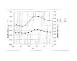
図5は本発明の屈曲振動片の振動漏れ指数と基部他端の連結痕の形成箇所の関係を示すグラフである。ここで、計算に用いる屈曲振動片10の形状は、一例として、全長を860μm、支持腕40の延出方向の中心線から基部20の端部までの長さLを248μm、支持腕40の中心線から支持腕40の側辺までの長さを50μm、支持腕40の中心線から支持腕40側の振動腕30の側辺(振動片の内側の側辺)までの長さを155μm、支持腕40の中心線から基部20端部側の振動腕30の側辺(振動腕30の外側の側辺)までの長さを207μm、支持腕40の中心線から基部20他端の連結痕50a,50bの形成箇所(連結痕50a,50bの突出方向の中心線)までの長さをX、連結痕50a,50bは平面視で正方形であり、その突出方向の長さを30μm、溝部34の深さを45μm、ハンマーヘッド部36の幅を198μm、ハンマーヘッド部36の長さを237μm、として屈曲振動周波数を32.768kHz近傍としている。そして、この屈曲振動片10を膜厚20μmのシリコン系の導電性接着剤でパッケージにマウントした状態で、セラミック製のパッケージにマウントした状態を想定して次のように振動漏れを計算した。
FIG. 5 is a graph showing the relationship between the vibration leakage index of the flexural vibration piece of the present invention and the location where the connection mark is formed at the other end of the base. Here, as an example, the shape of the bending
屈曲振動片10の屈曲振動に起因する弾性エネルギーは、支持腕40を介して導電性接着剤に到達し、導電性接着剤の裏面(屈曲振動片10とは反対側)に仮想的に設けられ、パッケージの材料定数を有する半無限媒体に伝達したまま屈曲振動片10には戻らない、ことを条件にして計算をしている。
半無限媒体に伝達したこのエネルギーは、再び屈曲振動片10において屈曲振動に寄与することがないので、振動漏れによる損失になる。そしてこの振動漏れによる損失のみを考慮したQ値をQLeakとして定義した(振動漏れが大きくなると、QLeakは小さくなる)。また、後述するメカニズムからも容易に想像できるように、本発明は上記で示した寸法の絶対値、屈曲振動周波数、材料に依存するものではない。
The elastic energy resulting from the bending vibration of the bending
Since this energy transmitted to the semi-infinite medium does not contribute to bending vibration again in the bending
同グラフの縦軸は振動漏れ指数(Q0/QLeak)としている。ここで、Q0は基部20の他端24に連結痕50a,50bが存在しない場合の振動漏れのみを考慮したQ値であり、QLeakは基部20の他端24に連結痕50a,50bを2つ形成した場合の振動漏れのみを考慮したQ値を示している。同グラフの横軸は基部20の他端24の連結痕50a,50bの形成箇所(X/L)とし、X/L=0のとき支持腕40の中心線と連結痕50a,50bの中心が重なる位置となり、X/L=1のとき基部20の端部と連結痕50a,50bの中心が重なる位置となる。そして◆プロットは、図1に示す屈曲振動片10のように、基部20の一端22と他端24が基部本体を間に挟んで平行に形成されている形態の振動片の例を示すグラフである。また、■プロットは、図3に示す屈曲振動片10Aのように、基部20Aの他端24Aの形態が、縮幅部が形成されている形態の振動片の例を示すグラフである。なお、屈曲振動片10と屈曲振動片10Aとでは、縮幅部による振動漏れの抑制が非常に大きいために表示スケールを同一とした場合には、連結痕50a,50bの形成位置の違いによる振動漏れ指数の変化が読み取り難くなってしまう。このため、図5では、図中左側縦軸に、屈曲振動片10のスケールを示し、図中右側に、屈曲振動片10Aのスケールを示している。
The vertical axis of the graph is the vibration leakage index (Q0 / QLeak). Here, Q0 is a Q value considering only vibration leakage when the
図5においては、振動漏れ指数が1.0よりも小さいと、基部の他端に連結痕を備えない屈曲振動片よりも振動漏れが小さいことになる。図1に示す屈曲振動片10の場合、0.46<X/L<0.66の範囲に連結痕50a,50bが存在する場合に、振動漏れ指数が1.0を大きく超えることとなる。この範囲を百分率で表すと、46%<X/L<66%となる。この範囲は、概ね、基部の一端に形成された振動腕の支持腕側に形成されたテーパー部形成位置に対応した基部の他端の領域である。より具体的に示すと、支持腕の中心から前記テーパー部の中心までの距離をX1とした場合に、支持腕40の中心位置を基点にして支持腕40の中心からX 1 −0.1Lより大きくX 1 +0.1Lより小さい距離で示される領域である。
In FIG. 5, when the vibration leakage index is smaller than 1.0, the vibration leakage is smaller than that of the bending vibration piece having no connection trace at the other end of the base. In the case of the bending
振動腕30は、励振電極に所定の駆動電圧を印加することにより、所定の周波数で振動腕30が互いに接近または離間する向きに屈曲して振動するように構成されている。一対の振動腕30が互いに逆相で屈曲変形した場合、支持腕40が電極パッド44、導電性接着剤を介してパッケージに固定されるため、基部20は振動腕30の延びる方向に屈曲変形することになるが、特に支持腕40の基端と振動腕30の基端との間に位置する基部20の部分と、それに連なって、振動腕30の延びる方向とは反対方向に位置する基部20の部分は大きく屈曲することになる。を間の支持腕40で支持する屈曲振動片10は、振動腕30の屈曲動作に起因して、基部20の一端と他端との間で、圧縮応力又は引っ張り応力を繰り返す屈曲変形が生じている。このため、基部20の他端に連結痕のような錘が形成されると、支持腕40を中心として左右の振動腕30がバランス良く屈曲振動している状態において、連結痕によりモーメントが変わりアンバランスとなって振動漏れが発生し易くなる。46%<X/L<66%の範囲に連結痕50a,50bが存在する場合には、このような作用が顕著にあらわれているということができる。
The vibrating
一方、基部20の他端に連結痕50a,50bを配置した場合であっても、一対の振動腕30がバランス良く屈曲振動している状態において、支持腕40の中心に対して線対称に配置した複数の連結痕50a,50bにより、モーメントの変化を抑制した場合には、振動漏れの発生を低減することができる。すなわち、連結痕50a,50bを46%<X/L<66%(X 1 −0.1Lより大きくX 1 +0.1Lより小さい範囲)以外の範囲となるように、基部20の他端に配置した場合である。
On the other hand, even when the connection marks 50a and 50b are disposed at the other end of the
これに対し、図3に示す屈曲振動片10Aの場合には、連結痕50a,50bを配置する場所に関わらず、その全域において振動漏れ指数が小さくなっていることを図5から読み取ることができる。なお、当該グラフにおけるQ0も、屈曲振動片10の振動漏れ指数を示す際に用いた屈曲振動片におけるQ0と同じ値である。
このように、基部20Aの他端に、端部から中心へ向けて山形となる傾斜を設けた屈曲振動片10Aであっても、連結痕50a,50bの配置位置によって、その振動漏れの生じ易さには変化がある。具体的には、屈曲振動片10と同様に、百分率表示で、46%<X/L<66%の範囲で、振動漏れ指数の大きな上昇が生じている。このため、屈曲振動片10Aであっても、連結痕50a,50bは、基部20Aの他端において、46%<X/L<66%の範囲(X 1 −0.1Lより大きく離れた所からX 1 +0.1L未満まで離れた所までの範囲)を除く範囲に配置されるようにすると良い。
On the other hand, in the case of the bending
As described above, even in the bending
本発明は、上記実施例に限定されるものではなく、その技術的範囲内で様々な変形又は変更を加えて実施することができる。例えば、2本一対の振動腕は、先端にハンマーヘッド部を形成せず、基端から先端に向けて腕部を略直線状に延出させた形態であっても適用することができる。 The present invention is not limited to the above embodiments, and can be implemented with various modifications or changes within the technical scope thereof. For example, the pair of two vibrating arms can be applied even when the arm portion is extended substantially linearly from the proximal end to the distal end without forming the hammer head portion at the distal end.
また、本発明の屈曲振動片は、様々な構造のパッケージに搭載することができ、例えば発振回路を有する回路素子と組み合わせた発振器等、振動子以外の様々な振動デバイスに適用することができる。 Further, the flexural vibration piece of the present invention can be mounted on packages having various structures, and can be applied to various vibration devices other than vibrators such as an oscillator combined with a circuit element having an oscillation circuit.
また、本発明の屈曲振動片10,10Aは、発振回路を有する回路素子と組み合わせることによって、デジタル携帯電話、パーソナルコンピューター(モバイル型パーソナルコンピューター)、電子時計、ビデオレコーダー、ビデオカメラ、テレビ、ディジタルスチルカメラ、インクジェット式吐出装置(例えばインクジェットプリンター)、ラップトップ型パーソナルコンピューター、カーナビゲーション装置、ページャ、電子手帳(通信機能付も含む)、電子辞書、電卓、電子ゲーム機器、ワードプロセッサー、ワークステーション、テレビ電話、防犯用テレビモニター、電子双眼鏡、POS端末、医療機器(例えば電子体温計、血圧計、血糖計、心電図計測装置、超音波診断装置、電子内視鏡)、魚群探知機、各種測定機器、計器類(例えば、車両、航空機、船舶の計器類)、フライトシュミレーター等の電子機器として広範に用いることができる。
Further, the
また、本発明の屈曲振動片10,10Aは、自動車に搭載されている。屈曲振動片10,10Aは、キーレスエントリー、イモビライザー、カーナビゲーションシステム、カーエアコン、アンチロックブレーキシステム(ABS)、エアバック、タイヤ・プレッシャー・モニタリング・システム(TPMS:Tire Pressure Monitoring System)、エンジンコントロール、ハイブリッド自動車や電気自動車の電池モニター、車体姿勢制御システム、等の電子制御ユニット(ECU:electronic control unit)に広く適用できる。
Moreover, the bending
10,10A………屈曲振動片、20,20A………基部、22,22A………一端、24,24A………他端、30………振動腕、32………腕部、34………溝部、36………ハンマーヘッド部、40………支持腕、42………腕部、44………電極パッド、50a,50b………連結痕、51………連結部、60………水晶ウエハー、62………支持部。 10, 10A ......... Bending vibration piece, 20, 20A ......... Base, 22, 22A ......... One end, 24, 24A ......... Other end, 30 ......... Vibrating arm, 32 ......... Arms, 34 ......... groove, 36 ......... hammer head, 40 ......... support arm, 42 ......... arm, 44 ......... electrode pad, 50a, 50b ......... connection mark, 51 ......... connection, 60... Crystal wafer, 62.
Claims (10)
前記基部の一端側から延出している第1の振動腕および第2の振動腕と、
前記基部の前記一端側から前記振動腕の延出方向に沿って延出しており、前記延出方向に直交する幅方向において前記第1の振動腕と前記第2の振動腕との間に配置されている支持腕と、
前記基部の前記一端とは反対の他端側に設けられている複数の突出部と、
前記振動腕の前記基部との接続部に設けられているテーパー部と、
を備え、
前記支持腕の幅の中心を通り前記支持腕の前記延出方向に沿っている中心線から、前記基部の前記幅方向における端部までの距離をLとし、
前記中心線から、前記支持腕側に位置する前記テーパー部の幅の中心までの距離をX 1 とした場合に、
前記複数の突出部は、前記中心線からの前記幅方向に沿った距離がX 1 −0.1Lより大きくX 1 +0.1Lよりも小さい範囲を除いた前記他端側の領域に設けられていることを特徴とする屈曲振動片。 The base,
A first vibrating arm and a second vibrating arm extending from one end side of the base;
It extends along the extending direction of the vibrating arm from the one end side of the base, and is arranged between the first vibrating arm and the second vibrating arm in the width direction orthogonal to the extending direction. The supporting arm being
A plurality of protrusions provided on the other end opposite to the one end of the base;
A tapered portion provided at a connection portion with the base portion of the vibrating arm;
With
The distance from the center line passing through the center of the width of the support arm along the extending direction of the support arm to the end of the base in the width direction is L,
From the centerline, the distance to the center of the width of the tapered portion positioned on the supporting arm side when the X 1,
Wherein the plurality of protrusions provided on the other end side of a region in which the distance along the width direction except for the smaller range than larger X 1 + 0.1 L from X 1 -0.1L from the center line bending vibration piece, characterized in that there.
前記第2の振動腕は、前記基部から延出している第2の腕部、および前記第2の腕部の前記基部側とは反対側の先端に設けられ、前記第2の腕部よりも幅が大きい第2の拡幅部と、を備え、
前記支持腕の前記基部側とは反対側の先端が、前記延出方向において、前記第1の拡幅部と前記第2の拡幅部との間が最も狭くなっている位置と前記基部との間にあることを特徴とする請求項1または2に記載の屈曲振動片。 The first vibrating arm is provided at a first arm portion extending from the base portion and a tip of the first arm portion on a side opposite to the base portion side, and more than the first arm portion. A first widened portion having a large width;
The second vibrating arm is provided at a second arm portion extending from the base portion and a tip of the second arm portion on the side opposite to the base portion side, and more than the second arm portion. A second widened portion having a large width,
The tip of the support arm on the side opposite to the base side is between the base and the position where the distance between the first widened portion and the second widened portion is narrowest in the extending direction. The bending vibration piece according to claim 1 , wherein the bending vibration piece is provided.
前記連結部を切断する工程と、を含み、
前記中心線から前記基部の前記幅方向における端部までの距離をLとし、
前記中心線から、前記支持腕側に位置する前記テーパー部の幅の中心までの距離をX 1 とした場合に、
前記複数の連結部は、前記中心線からの前記幅方向に沿った距離がX 1 −0.1Lより大きくX 1 +0.1Lよりも小さい範囲を除いた前記他端側の領域に設けられていることを特徴とする屈曲振動片の製造方法。 Base, the first vibrating arm and the second vibrating arm extending from one end of the base portion, and extends from the one end side of the front SL base along the extending direction of the vibrating arm, leaving the extension A support arm disposed between the first vibrating arm and the second vibrating arm in a width direction perpendicular to the direction, and a tapered portion provided at a connection portion between the vibrating arm and the base. A bending vibration piece provided; a support portion disposed on the other end side of the base portion; and the other end side of the base portion, passing through the center of the width of the support arm in the extending direction of the support arm. Providing a structure including a plurality of connecting portions that are provided at symmetrical positions with respect to a center line that is along, and that connect the base portion and the support portion; and
Cutting the connecting portion, and
The distance from the center line to the end of the base in the width direction is L,
From the centerline, the distance to the center of the width of the tapered portion positioned on the supporting arm side when the X 1,
Wherein the plurality of connecting portions, provided on the other end side of a region in which the distance along the width direction except for the smaller range than larger X 1 + 0.1 L from X 1 -0.1L from the center line A method of manufacturing a flexural vibration piece, comprising:
Priority Applications (1)
| Application Number | Priority Date | Filing Date | Title |
|---|---|---|---|
| JP2013050101A JP6115205B2 (en) | 2013-03-13 | 2013-03-13 | Bending vibration piece, method for manufacturing bending vibration piece, vibration device, electronic apparatus, and moving body |
Applications Claiming Priority (1)
| Application Number | Priority Date | Filing Date | Title |
|---|---|---|---|
| JP2013050101A JP6115205B2 (en) | 2013-03-13 | 2013-03-13 | Bending vibration piece, method for manufacturing bending vibration piece, vibration device, electronic apparatus, and moving body |
Publications (3)
| Publication Number | Publication Date |
|---|---|
| JP2014176064A JP2014176064A (en) | 2014-09-22 |
| JP2014176064A5 JP2014176064A5 (en) | 2016-03-31 |
| JP6115205B2 true JP6115205B2 (en) | 2017-04-19 |
Family
ID=51696863
Family Applications (1)
| Application Number | Title | Priority Date | Filing Date |
|---|---|---|---|
| JP2013050101A Active JP6115205B2 (en) | 2013-03-13 | 2013-03-13 | Bending vibration piece, method for manufacturing bending vibration piece, vibration device, electronic apparatus, and moving body |
Country Status (1)
| Country | Link |
|---|---|
| JP (1) | JP6115205B2 (en) |
Family Cites Families (10)
| Publication number | Priority date | Publication date | Assignee | Title |
|---|---|---|---|---|
| JPS52129395A (en) * | 1976-04-23 | 1977-10-29 | Seiko Instr & Electronics Ltd | Tuner fork type peizoelectric resonatpr |
| JPH0298522U (en) * | 1988-04-06 | 1990-08-06 | ||
| JP2002141770A (en) * | 2000-11-01 | 2002-05-17 | Citizen Watch Co Ltd | Small-sized vibrator |
| JP2004297769A (en) * | 2003-03-13 | 2004-10-21 | Seiko Epson Corp | Crystal oscillating piece, method of manufacturing the piece, crystal device housing the piece in package, and electronic equipment using the crustal device |
| JP4517332B2 (en) * | 2003-04-28 | 2010-08-04 | 有限会社ピエデック技術研究所 | Quartz crystal unit, crystal unit and crystal oscillator manufacturing method |
| JP4301201B2 (en) * | 2005-04-27 | 2009-07-22 | セイコーエプソン株式会社 | Piezoelectric oscillator |
| ATE421799T1 (en) * | 2005-06-09 | 2009-02-15 | Eta Sa Mft Horlogere Suisse | COMPACT PIEZOELECTRIC RESONATOR |
| JP2009060478A (en) * | 2007-09-03 | 2009-03-19 | Nippon Dempa Kogyo Co Ltd | Manufacturing method of piezoelectric vibration chip, and tuning fork type piezoelectric vibration chip |
| JP5216288B2 (en) * | 2007-09-25 | 2013-06-19 | 日本電波工業株式会社 | Method for manufacturing piezoelectric vibrating piece, method for manufacturing piezoelectric device |
| JP2012105044A (en) * | 2010-11-10 | 2012-05-31 | Seiko Epson Corp | Vibration device and electronic apparatus |
-
2013
- 2013-03-13 JP JP2013050101A patent/JP6115205B2/en active Active
Also Published As
| Publication number | Publication date |
|---|---|
| JP2014176064A (en) | 2014-09-22 |
Similar Documents
| Publication | Publication Date | Title |
|---|---|---|
| US8692632B2 (en) | Resonator element, resonator, oscillator, and electronic device | |
| CN110071701B (en) | Vibrating element, method for manufacturing the same, physical quantity sensor, and inertial measurement device | |
| US9425768B2 (en) | Resonator element, resonator device, electronic apparatus, moving object, and method of manufacturing resonator element | |
| JP2007300287A (en) | Surface acoustic wave element, surface acoustic wave device, and electronic apparatus | |
| JP5581887B2 (en) | Vibrating piece, vibrator, oscillator, electronic device, and frequency adjustment method | |
| US10659006B2 (en) | Resonator element, resonator, electronic device, electronic apparatus, and moving object | |
| US9490773B2 (en) | Vibrating element, electronic device, electronic apparatus, and moving object | |
| US9246471B2 (en) | Resonator element, resonator, oscillator, electronic device, and mobile object | |
| US20130320812A1 (en) | Vibrating reed, electronic device, and electronic apparatus | |
| JP2015035734A (en) | Vibration element, vibration device, electronic apparatus, and mobile body | |
| US9354128B2 (en) | Resonator element, resonator, oscillator, electronic apparatus, sensor, and mobile object | |
| US10128430B2 (en) | Vibration element manufacturing method, vibration element, electronic device, electronic apparatus, and moving object | |
| US20140001921A1 (en) | Resonator element, piezoelectric device, and electronic device | |
| JP2017120194A (en) | Sensor substrate, physical quantity detection sensor, acceleration sensor, electronic apparatus, and movable body | |
| JP5760413B2 (en) | Electronics | |
| JP6115205B2 (en) | Bending vibration piece, method for manufacturing bending vibration piece, vibration device, electronic apparatus, and moving body | |
| JP2015128269A (en) | Vibrator, oscillator, electronic apparatus, physical quantity sensor and movable body | |
| JP6286842B2 (en) | Bending vibration piece, vibration device, electronic device, and moving body | |
| JP6070343B2 (en) | Bending vibration piece, vibration device, electronic device, and moving body | |
| US9287848B2 (en) | Resonator element, resonator, oscillator, electronic apparatus, and moving object having reduced vibration leakage | |
| JP2016065752A (en) | Vibration piece, angular velocity sensor, electronic apparatus and movable body | |
| JP6111754B2 (en) | Bending vibration piece, method for manufacturing bending vibration piece, vibration device, electronic apparatus, and moving body | |
| US9444403B2 (en) | Resonation element, resonator, oscillator, electronic device and moving object | |
| JP2016085191A (en) | Vibration element, manufacturing method of the same, electronic device, electronic apparatus and movable body | |
| JP2016092466A (en) | Vibration element, method for manufacturing vibration element, electronic device, electronic equipment and mobile body |
Legal Events
| Date | Code | Title | Description |
|---|---|---|---|
| RD04 | Notification of resignation of power of attorney |
Free format text: JAPANESE INTERMEDIATE CODE: A7424 Effective date: 20150109 |
|
| A521 | Written amendment |
Free format text: JAPANESE INTERMEDIATE CODE: A523 Effective date: 20160216 |
|
| A621 | Written request for application examination |
Free format text: JAPANESE INTERMEDIATE CODE: A621 Effective date: 20160216 |
|
| RD04 | Notification of resignation of power of attorney |
Free format text: JAPANESE INTERMEDIATE CODE: A7424 Effective date: 20160610 |
|
| RD03 | Notification of appointment of power of attorney |
Free format text: JAPANESE INTERMEDIATE CODE: A7423 Effective date: 20160624 |
|
| A977 | Report on retrieval |
Free format text: JAPANESE INTERMEDIATE CODE: A971007 Effective date: 20161111 |
|
| A131 | Notification of reasons for refusal |
Free format text: JAPANESE INTERMEDIATE CODE: A131 Effective date: 20161122 |
|
| A521 | Written amendment |
Free format text: JAPANESE INTERMEDIATE CODE: A523 Effective date: 20170119 |
|
| TRDD | Decision of grant or rejection written | ||
| A01 | Written decision to grant a patent or to grant a registration (utility model) |
Free format text: JAPANESE INTERMEDIATE CODE: A01 Effective date: 20170221 |
|
| A61 | First payment of annual fees (during grant procedure) |
Free format text: JAPANESE INTERMEDIATE CODE: A61 Effective date: 20170306 |
|
| R150 | Certificate of patent or registration of utility model |
Ref document number: 6115205 Country of ref document: JP Free format text: JAPANESE INTERMEDIATE CODE: R150 |