JP6114822B2 - System and method for 3D ultrasonic volume measurement - Google Patents
System and method for 3D ultrasonic volume measurement Download PDFInfo
- Publication number
- JP6114822B2 JP6114822B2 JP2015517899A JP2015517899A JP6114822B2 JP 6114822 B2 JP6114822 B2 JP 6114822B2 JP 2015517899 A JP2015517899 A JP 2015517899A JP 2015517899 A JP2015517899 A JP 2015517899A JP 6114822 B2 JP6114822 B2 JP 6114822B2
- Authority
- JP
- Japan
- Prior art keywords
- cursor
- point
- imaging system
- ultrasound imaging
- image
- Prior art date
- Legal status (The legal status is an assumption and is not a legal conclusion. Google has not performed a legal analysis and makes no representation as to the accuracy of the status listed.)
- Active
Links
- 238000005259 measurement Methods 0.000 title claims description 33
- 238000000034 method Methods 0.000 title claims description 20
- 238000002604 ultrasonography Methods 0.000 claims description 59
- 230000033001 locomotion Effects 0.000 claims description 45
- 238000012285 ultrasound imaging Methods 0.000 claims description 40
- 230000000007 visual effect Effects 0.000 claims description 20
- 230000008859 change Effects 0.000 claims description 12
- 238000004590 computer program Methods 0.000 claims description 6
- 238000003384 imaging method Methods 0.000 claims description 4
- 239000000523 sample Substances 0.000 description 16
- 238000012545 processing Methods 0.000 description 11
- 238000010586 diagram Methods 0.000 description 10
- 230000000694 effects Effects 0.000 description 9
- 210000003484 anatomy Anatomy 0.000 description 4
- 230000001419 dependent effect Effects 0.000 description 3
- 238000001514 detection method Methods 0.000 description 3
- 230000007246 mechanism Effects 0.000 description 3
- 230000008901 benefit Effects 0.000 description 2
- 230000005540 biological transmission Effects 0.000 description 2
- 238000005516 engineering process Methods 0.000 description 2
- 238000001914 filtration Methods 0.000 description 2
- 230000010349 pulsation Effects 0.000 description 2
- 102100025283 Gap junction alpha-8 protein Human genes 0.000 description 1
- 210000004204 blood vessel Anatomy 0.000 description 1
- 238000006243 chemical reaction Methods 0.000 description 1
- 238000004891 communication Methods 0.000 description 1
- 230000006835 compression Effects 0.000 description 1
- 238000007906 compression Methods 0.000 description 1
- 238000002592 echocardiography Methods 0.000 description 1
- 230000006870 function Effects 0.000 description 1
- 239000011521 glass Substances 0.000 description 1
- 230000006872 improvement Effects 0.000 description 1
- 239000011159 matrix material Substances 0.000 description 1
- 238000000691 measurement method Methods 0.000 description 1
- 238000012986 modification Methods 0.000 description 1
- 230000004048 modification Effects 0.000 description 1
- 230000003287 optical effect Effects 0.000 description 1
- 230000009467 reduction Effects 0.000 description 1
- 239000007787 solid Substances 0.000 description 1
Images


Classifications
-
- A—HUMAN NECESSITIES
- A61—MEDICAL OR VETERINARY SCIENCE; HYGIENE
- A61B—DIAGNOSIS; SURGERY; IDENTIFICATION
- A61B8/00—Diagnosis using ultrasonic, sonic or infrasonic waves
- A61B8/52—Devices using data or image processing specially adapted for diagnosis using ultrasonic, sonic or infrasonic waves
- A61B8/5215—Devices using data or image processing specially adapted for diagnosis using ultrasonic, sonic or infrasonic waves involving processing of medical diagnostic data
- A61B8/5223—Devices using data or image processing specially adapted for diagnosis using ultrasonic, sonic or infrasonic waves involving processing of medical diagnostic data for extracting a diagnostic or physiological parameter from medical diagnostic data
-
- A—HUMAN NECESSITIES
- A61—MEDICAL OR VETERINARY SCIENCE; HYGIENE
- A61B—DIAGNOSIS; SURGERY; IDENTIFICATION
- A61B5/00—Measuring for diagnostic purposes; Identification of persons
- A61B5/74—Details of notification to user or communication with user or patient ; user input means
- A61B5/7405—Details of notification to user or communication with user or patient ; user input means using sound
-
- A—HUMAN NECESSITIES
- A61—MEDICAL OR VETERINARY SCIENCE; HYGIENE
- A61B—DIAGNOSIS; SURGERY; IDENTIFICATION
- A61B5/00—Measuring for diagnostic purposes; Identification of persons
- A61B5/74—Details of notification to user or communication with user or patient ; user input means
- A61B5/7455—Details of notification to user or communication with user or patient ; user input means characterised by tactile indication, e.g. vibration or electrical stimulation
-
- A—HUMAN NECESSITIES
- A61—MEDICAL OR VETERINARY SCIENCE; HYGIENE
- A61B—DIAGNOSIS; SURGERY; IDENTIFICATION
- A61B8/00—Diagnosis using ultrasonic, sonic or infrasonic waves
- A61B8/13—Tomography
- A61B8/14—Echo-tomography
- A61B8/145—Echo-tomography characterised by scanning multiple planes
-
- A—HUMAN NECESSITIES
- A61—MEDICAL OR VETERINARY SCIENCE; HYGIENE
- A61B—DIAGNOSIS; SURGERY; IDENTIFICATION
- A61B8/00—Diagnosis using ultrasonic, sonic or infrasonic waves
- A61B8/44—Constructional features of the ultrasonic, sonic or infrasonic diagnostic device
- A61B8/4483—Constructional features of the ultrasonic, sonic or infrasonic diagnostic device characterised by features of the ultrasound transducer
-
- A—HUMAN NECESSITIES
- A61—MEDICAL OR VETERINARY SCIENCE; HYGIENE
- A61B—DIAGNOSIS; SURGERY; IDENTIFICATION
- A61B8/00—Diagnosis using ultrasonic, sonic or infrasonic waves
- A61B8/46—Ultrasonic, sonic or infrasonic diagnostic devices with special arrangements for interfacing with the operator or the patient
- A61B8/461—Displaying means of special interest
- A61B8/466—Displaying means of special interest adapted to display 3D data
-
- A—HUMAN NECESSITIES
- A61—MEDICAL OR VETERINARY SCIENCE; HYGIENE
- A61B—DIAGNOSIS; SURGERY; IDENTIFICATION
- A61B8/00—Diagnosis using ultrasonic, sonic or infrasonic waves
- A61B8/46—Ultrasonic, sonic or infrasonic diagnostic devices with special arrangements for interfacing with the operator or the patient
- A61B8/467—Ultrasonic, sonic or infrasonic diagnostic devices with special arrangements for interfacing with the operator or the patient characterised by special input means
- A61B8/469—Ultrasonic, sonic or infrasonic diagnostic devices with special arrangements for interfacing with the operator or the patient characterised by special input means for selection of a region of interest
-
- A—HUMAN NECESSITIES
- A61—MEDICAL OR VETERINARY SCIENCE; HYGIENE
- A61B—DIAGNOSIS; SURGERY; IDENTIFICATION
- A61B8/00—Diagnosis using ultrasonic, sonic or infrasonic waves
- A61B8/48—Diagnostic techniques
- A61B8/483—Diagnostic techniques involving the acquisition of a 3D volume of data
-
- A—HUMAN NECESSITIES
- A61—MEDICAL OR VETERINARY SCIENCE; HYGIENE
- A61B—DIAGNOSIS; SURGERY; IDENTIFICATION
- A61B8/00—Diagnosis using ultrasonic, sonic or infrasonic waves
- A61B8/54—Control of the diagnostic device
-
- G—PHYSICS
- G01—MEASURING; TESTING
- G01S—RADIO DIRECTION-FINDING; RADIO NAVIGATION; DETERMINING DISTANCE OR VELOCITY BY USE OF RADIO WAVES; LOCATING OR PRESENCE-DETECTING BY USE OF THE REFLECTION OR RERADIATION OF RADIO WAVES; ANALOGOUS ARRANGEMENTS USING OTHER WAVES
- G01S15/00—Systems using the reflection or reradiation of acoustic waves, e.g. sonar systems
- G01S15/88—Sonar systems specially adapted for specific applications
- G01S15/89—Sonar systems specially adapted for specific applications for mapping or imaging
- G01S15/8906—Short-range imaging systems; Acoustic microscope systems using pulse-echo techniques
- G01S15/8993—Three dimensional imaging systems
-
- G—PHYSICS
- G01—MEASURING; TESTING
- G01S—RADIO DIRECTION-FINDING; RADIO NAVIGATION; DETERMINING DISTANCE OR VELOCITY BY USE OF RADIO WAVES; LOCATING OR PRESENCE-DETECTING BY USE OF THE REFLECTION OR RERADIATION OF RADIO WAVES; ANALOGOUS ARRANGEMENTS USING OTHER WAVES
- G01S7/00—Details of systems according to groups G01S13/00, G01S15/00, G01S17/00
- G01S7/52—Details of systems according to groups G01S13/00, G01S15/00, G01S17/00 of systems according to group G01S15/00
- G01S7/52017—Details of systems according to groups G01S13/00, G01S15/00, G01S17/00 of systems according to group G01S15/00 particularly adapted to short-range imaging
- G01S7/52053—Display arrangements
- G01S7/52057—Cathode ray tube displays
- G01S7/52073—Production of cursor lines, markers or indicia by electronic means
-
- G—PHYSICS
- G06—COMPUTING; CALCULATING OR COUNTING
- G06T—IMAGE DATA PROCESSING OR GENERATION, IN GENERAL
- G06T19/00—Manipulating 3D models or images for computer graphics
-
- G—PHYSICS
- G16—INFORMATION AND COMMUNICATION TECHNOLOGY [ICT] SPECIALLY ADAPTED FOR SPECIFIC APPLICATION FIELDS
- G16H—HEALTHCARE INFORMATICS, i.e. INFORMATION AND COMMUNICATION TECHNOLOGY [ICT] SPECIALLY ADAPTED FOR THE HANDLING OR PROCESSING OF MEDICAL OR HEALTHCARE DATA
- G16H50/00—ICT specially adapted for medical diagnosis, medical simulation or medical data mining; ICT specially adapted for detecting, monitoring or modelling epidemics or pandemics
- G16H50/30—ICT specially adapted for medical diagnosis, medical simulation or medical data mining; ICT specially adapted for detecting, monitoring or modelling epidemics or pandemics for calculating health indices; for individual health risk assessment
-
- G—PHYSICS
- G01—MEASURING; TESTING
- G01S—RADIO DIRECTION-FINDING; RADIO NAVIGATION; DETERMINING DISTANCE OR VELOCITY BY USE OF RADIO WAVES; LOCATING OR PRESENCE-DETECTING BY USE OF THE REFLECTION OR RERADIATION OF RADIO WAVES; ANALOGOUS ARRANGEMENTS USING OTHER WAVES
- G01S15/00—Systems using the reflection or reradiation of acoustic waves, e.g. sonar systems
- G01S15/88—Sonar systems specially adapted for specific applications
- G01S15/89—Sonar systems specially adapted for specific applications for mapping or imaging
-
- G—PHYSICS
- G06—COMPUTING; CALCULATING OR COUNTING
- G06T—IMAGE DATA PROCESSING OR GENERATION, IN GENERAL
- G06T2219/00—Indexing scheme for manipulating 3D models or images for computer graphics
- G06T2219/012—Dimensioning, tolerancing
Description
本発明は、例えば患者の解剖学的部位のようなボリュームの3次元超音波画像において第1のポイントと第2のポイントとの間の距離を決定する超音波イメージングシステム及び方法に関する。本発明は更に、このような方法を実現するためのコンピュータプログラムに関する。 The present invention relates to an ultrasound imaging system and method for determining a distance between a first point and a second point in a three-dimensional ultrasound image of a volume, such as a patient anatomy. The invention further relates to a computer program for implementing such a method.
3次元超音波イメージング又はボリュームイメージングにおいて、3次元画像の取得は、関心のあるボリュームをスライスする多くの2次元スキャンによって実施されている。それゆえ、互いに隣り合う複数の2次元画像が取得される。適切な画像処理によって、関心ボリュームの3次元画像が、複数の2次元画像から構築されることができる。複数の2次元画像から取得される3次元情報は、超音波システムのユーザのためにディスプレイ上に適切な形で表示される。 In 3D ultrasound imaging or volume imaging, acquisition of 3D images is performed by a number of 2D scans that slice the volume of interest. Therefore, a plurality of adjacent two-dimensional images are acquired. With appropriate image processing, a three-dimensional image of the volume of interest can be constructed from a plurality of two-dimensional images. The three-dimensional information obtained from the plurality of two-dimensional images is displayed in an appropriate form on the display for the user of the ultrasound system.
更に、3次元超音波イメージングにおいて、しばしば、検査されたボリューム内の解剖学的構造の測定を行うためのニーズがある。ユーザに対する便宜のため、測定能力は、3次元超音波イメージングシステムにおいて利用可能であり、そのシステムにおいて、ユーザは、それらの解剖学的構造を含む3次元ボリュームのレンダリングされた画像上で直接的な測定を実施することができる。このいわゆる「オングラス」測定方法は、非常に容易であり、ユーザにとって便利である。しかしながら、この技法は、いわゆる「フォアショートニング効果」に影響されやすい。測定されている構造が、3次元ボリュームの投影画像の面と同じ面にない場合、スクリーン上で見られるような構造間の測定される距離は、実際の3次元空間における構造間の真の距離より小さい。 In addition, in 3D ultrasound imaging, there is often a need to perform anatomical measurements within the examined volume. For convenience to the user, measurement capabilities are available in a 3D ultrasound imaging system, where the user can directly operate on a rendered image of a 3D volume containing their anatomy. Measurements can be performed. This so-called “on-glass” measurement method is very easy and convenient for the user. However, this technique is susceptible to the so-called “foreshortening effect”. If the structure being measured is not in the same plane as the projected image plane of the 3D volume, the measured distance between the structures as seen on the screen is the true distance between the structures in the actual 3D space. Smaller than.
従って、3次元超音波画像において測定を実施する超音波システム及び方法が企図されている。米国特許出願公開第2011/0066031号明細書は、3次元測定を実施する超音波システムであって、ターゲット対象に超音波信号を送信し、ターゲット対象から反射された超音波エコー信号を受け取って、超音波データを取得するように構成される超音波データ取得ユニットを有する超音波システムを提供する実施形態を開示する。更に、超音波システムは、ユーザからの入力データを受け取るように構成されるユーザインタフェースと、超音波データから導き出されたボリュームデータに基づく3次元超音波画像を形成し、入力データに基づいて3D超音波画像上に2又はそれより多くのポイントを確立し、3D超音波画像上の確立された2又はそれより多くのポイントの間でデータを接続し、入力データ及び接続データに基づいて、確立された2又はそれより多くのポイントの間の距離を測定するように構成されるプロセッサと、を有する。 Accordingly, an ultrasound system and method for performing measurements on three-dimensional ultrasound images is contemplated. US Patent Application Publication No. 2011/0066031 is an ultrasound system that performs a three-dimensional measurement, transmits an ultrasound signal to a target object, receives an ultrasound echo signal reflected from the target object, and Embodiments are disclosed that provide an ultrasound system having an ultrasound data acquisition unit configured to acquire ultrasound data. In addition, the ultrasound system forms a 3D ultrasound image based on the input data and a user interface configured to receive input data from the user and volume data derived from the ultrasound data. Establish two or more points on the ultrasound image, connect data between the established two or more points on the 3D ultrasound image, and establish based on the input data and connection data And a processor configured to measure a distance between two or more points.
更にこのような3次元超音波システムを改善するニーズがある。 There is a further need to improve such 3D ultrasound systems.
本発明の目的は、改善された超音波システム及び方法を提供することである。本発明の他の目的は、このような方法を実現するためのコンピュータプログラムを提供することである。 It is an object of the present invention to provide an improved ultrasound system and method. Another object of the present invention is to provide a computer program for realizing such a method.
本発明の第1の見地において、ボリュームの3次元画像を提供する超音波イメージングシステムが示される。超音波イメージングシステムは、超音波受信信号を供給するように構成されるトランスデューサアレイと、超音波受信信号を受け取り、3次元画像を表現する表示データを供給するように構成される制御ユニットであって、3次元画像において識別される第1のポイントと第2のポイントとの間の距離を決定するように更に構成される制御ユニットと、表示データを受け取り、ボリュームの3次元画像を供給するように構成されるディスプレイと、第1のポイント及び第2のポイントを識別するためのカーソルと、入力データを制御ユニットに供給するように構成される入力装置であって、入力データがカーソルの移動を含む、入力装置と、を有し、超音波イメージングシステムは、ディスプレイ上に提供される3次元画像の面内のカーソルの第1の移動と、面に垂直なカーソルの第2の移動を可能にするように構成される。 In a first aspect of the invention, an ultrasound imaging system that provides a three-dimensional image of a volume is shown. The ultrasound imaging system is a transducer array configured to supply an ultrasound reception signal and a control unit configured to receive the ultrasound reception signal and supply display data representing a three-dimensional image. A control unit further configured to determine a distance between a first point and a second point identified in the three-dimensional image, and to receive the display data and provide a three-dimensional image of the volume A display configured, a cursor for identifying a first point and a second point, and an input device configured to supply input data to the control unit, the input data including movement of the cursor An ultrasound imaging system having an in-plane cursor for a three-dimensional image provided on the display First and mobile, configured to allow the second movement perpendicular cursor plane.
本発明の他の見地において、ボリュームの3次元超音波画像において第1のポイントと第2のポイントとの間の距離を算出す方法が提示される。方法は、第1のポイント及び第2のポイントを識別するためのカーソルと共に、ディスプレイ上に3次元超音波画像を表示するステップと、第1及び第2のポイントの少なくとも一方の第1の座標及び第2の座標を識別するために、入力データに基づいてディスプレイに提供された面と平行にカーソルを移動させるステップと、個々のポイントの第3の座標を識別するために、入力データに基づいてディスプレイ上に提供された面に垂直にカーソルを移動させるステップと、カーソルがボリューム内に表示される構造と衝突する場合に標示を提供するステップと、第1のポイントと第2のポイントとの間の距離を算出するステップと、を含む。 In another aspect of the invention, a method is provided for calculating a distance between a first point and a second point in a three-dimensional ultrasound image of a volume. The method includes displaying a three-dimensional ultrasound image on a display with a cursor for identifying the first point and the second point, first coordinates of at least one of the first and second points, and Moving the cursor parallel to the plane provided on the display based on the input data to identify the second coordinates, and based on the input data to identify the third coordinates of the individual points. Moving the cursor perpendicular to the surface provided on the display; providing an indication when the cursor collides with a structure displayed in the volume; and between the first point and the second point. Calculating a distance of.
本発明の他の見地において、コンピュータプログラムがコンピュータ上で実行されるとき、このような方法の各ステップをコンピュータに実施させるプログラムコード手段を含むコンピュータプログラムが提示される。 In another aspect of the present invention, when a computer program is executed on a computer, a computer program is provided that includes program code means for causing the computer to perform the steps of such a method.
本発明の基本的な考えは、3次元画像において測定されることができる構造に到達するように、測定カーソルをボリューム内に直接置く可能性をユーザに提供することによって、「フォアショートニング効果」を克服することである。 The basic idea of the present invention is to provide a “foreshortening effect” by providing the user with the possibility to place the measurement cursor directly in the volume to reach a structure that can be measured in a three-dimensional image. It is to overcome.
これによって、ユーザは、ディスプレイに表示された面内にカーソルを配置することしかできないという問題が、解決されることができる。更に、ユーザが、3次元ボリューム内の構造に到達する適切な位置にカーソルを位置付けることが可能である該適切な位置を見つけるために、3次元ボリュームを広範囲に回転する必要がない。その代わりに、ユーザは、最初にディスプレイに表示される3次元ボリュームの面にカーソルを位置付けることができ、次いで、カーソルが構造に到達するまで、カーソルをボリューム内で「降下させる」ことができる。 This can solve the problem that the user can only place the cursor in the plane displayed on the display. Furthermore, it is not necessary to rotate the 3D volume extensively in order to find the appropriate position where the user can position the cursor at the appropriate position to reach the structure in the 3D volume. Instead, the user can position the cursor on the plane of the three-dimensional volume that is initially displayed on the display, and then “drop” the cursor in the volume until the cursor reaches the structure.
ユーザは、スクリーンの次元(例えばx及びy次元)内に終点を配置するためのトラックボールに加えて、例えばz次元について、カーソル終点深さ制御手段を提供される。測定されるべき構造の上方において、例えばトラックボールにより、面内で第1のポイント又は第2のポイントを配置した後、ユーザは、カーソルをボリューム内に下降させるよう移動させるために、終点深さ制御手段を使用する。両方のポイントが同様に配置された後、超音波イメージングシステムは、ポイント間の真の3次元距離を計算する。次に、超音波イメージングシステムは、「長さ」測定として距離を示すことができる。 The user is provided with cursor endpoint depth control means, for example for the z dimension, in addition to the trackball for placing the end points in the screen dimensions (eg, x and y dimensions). After placing the first point or the second point in the plane above the structure to be measured, for example by a trackball, the user moves the cursor to the end point depth to move it down into the volume. Use control means. After both points are placed similarly, the ultrasound imaging system calculates the true three-dimensional distance between the points. The ultrasound imaging system can then indicate the distance as a “length” measurement.
このため、第1及び第2のポイントが構造に到達し、ボリューム内のいかなる場所にも浮遊してないことが確実にされる。それゆえ、「フォアショートニング効果」は生じ得ない。 This ensures that the first and second points reach the structure and do not float anywhere in the volume. Therefore, the “foreshortening effect” cannot occur.
本発明の好適な実施形態は、従属請求項に規定される。請求項に記載の方法は、請求項に記載の装置と従属請求項に記載されるものと同様の及び/又は同一の好適な実施形態を有することが理解されるべきである。 Preferred embodiments of the invention are defined in the dependent claims. It is to be understood that the claimed method has preferred embodiments that are similar and / or identical to those described in the claim and the dependent claims.
一実施形態において、超音波イメージングシステムは、第1の移動が終了された後、第2の移動を可能にするように構成される。これによって、ユーザは、ディスプレイに表示される面内でまずカーソルを移動させることができる。適切な位置に到達した場合、ユーザは、この位置を固定することができ、それゆえ、第1及び第2のポイントの第1及び第2の座標が決定される。その後、ユーザは、測定されるべき構造に適切に到達するようにカーソルを配置するために、面に対し垂直にカーソルを移動させることができる。これによって、第3の座標が決定されることができる。この第2の移動の最中、第1及び第2の座標は固定されたままであることができるので、3次元画像内でのアライメント及び方向付けが容易にされる。 In one embodiment, the ultrasound imaging system is configured to allow a second movement after the first movement is finished. Thus, the user can first move the cursor within the plane displayed on the display. When the proper position is reached, the user can fix this position and therefore the first and second coordinates of the first and second points are determined. The user can then move the cursor perpendicular to the surface to position the cursor appropriately to reach the structure to be measured. Thereby, the third coordinate can be determined. During this second movement, the first and second coordinates can remain fixed, facilitating alignment and orientation within the three-dimensional image.
他の実施形態において、超音波イメージングシステムは、第2の移動及び第1の移動を同時に実現可能にするように構成される。これによって、3次元画像内での発展したナビゲーションが必要とされるが、カーソルの位置付けは加速されることができる。 In other embodiments, the ultrasound imaging system is configured to allow the second movement and the first movement to be performed simultaneously. This requires advanced navigation within the 3D image, but the cursor positioning can be accelerated.
他の実施形態において、超音波イメージングシステムは、第2の移動を自動的に実施するように構成される。これは、第1及び第2の移動が続けて実施される場合に実現されうる。しかしながら、これは、第2の移動が第1の移動と同時に実施される場合にも実現されることができる。自動的な第2の移動は、衝突検出が行われるようなやり方で実施されることができ、かかる衝突検出は、第1の移動が実施される面から始まって、カーソルとボリューム内の構造との間の最初の衝突を決定することが可能である。言い換えると、超音波イメージングシステムは、ボリューム内を下降するように第3の次元においてカーソルを自動的に移動させ、カーソルと構造との間の最初の衝突を検出する。第2の移動が第1の移動に続いて実施される場合、ユーザは、入力装置を介して、例えば対応するボタンを打つことによって、自動的な第2の移動をアクティブにすることを可能にされる。更に、ユーザは、手作業で衝突のポイントのロケーションを補正することを可能にされることができる。第1及び第2の移動が同時に実施される場合、ユーザは、第1の移動を実施しながら、すなわち第1及び第2の座標を変更しながら、自動的な第2の移動をアクティブにしたままにすることを可能にされることができる。こうして、対応する第3の座標が連続的に決定される。第3の座標は、ユーザに表示されることができる。これによって、ユーザは、第1の移動を実施しながら構造の表面を追跡することが可能であるという利点が提供されることができる。これは、ディスプレイに表示される構造の3次元形状についての印象を得ることを容易にすることができる。 In other embodiments, the ultrasound imaging system is configured to automatically perform the second movement. This can be realized when the first and second movements are performed in succession. However, this can also be realized if the second movement is performed simultaneously with the first movement. The automatic second movement can be performed in such a way that collision detection is performed, such collision detection starting from the plane on which the first movement is performed, and the structure of the cursor and the volume. It is possible to determine the first collision between. In other words, the ultrasound imaging system automatically moves the cursor in the third dimension to descend through the volume and detects the first collision between the cursor and the structure. If the second movement is performed following the first movement, the user can activate the automatic second movement via the input device, for example by hitting the corresponding button. Is done. In addition, the user can be allowed to manually correct the location of the point of collision. If the first and second movements are performed at the same time, the user has activated the automatic second movement while performing the first movement, i.e., changing the first and second coordinates. Can be allowed to remain. In this way, the corresponding third coordinates are continuously determined. The third coordinate can be displayed to the user. This can provide the advantage that the user can track the surface of the structure while performing the first movement. This can facilitate obtaining an impression of the three-dimensional shape of the structure displayed on the display.
他の実施形態において、超音波イメージングシステムは更に、カーソルがボリューム内の構造と衝突する場合に標示を提供するように構成される。これによって、ボリューム内での第1及び第2のポイントの位置付けがなお一層容易にされる。これは、例えば視覚的標示、オーディオ標示又は触覚感知標示のような任意の十分なタイプでありうる標示を提供することによって、行われる。ユーザは、第1の移動の最中、ディスプレイに表示される面内にカーソルを位置付けることができる。次に、第2の移動は、ディスプレイに表示されるビューのパースペクティブを変える必要なく、実施されることができる。カーソルが例えばボリューム内の解剖学的構造のような構造に到達する又は構造と衝突する場合に標示が与えられるので、第2の移動は、表示された面に対し単に垂直であるので、第2の移動は、それがディスプレイ上では可視でないが、実施されることができる。これは、超音波イメージングシステムに入力すること、及びボリュームの観察中に測定を行うことを容易にする。 In other embodiments, the ultrasound imaging system is further configured to provide an indication when the cursor collides with a structure in the volume. This further facilitates the positioning of the first and second points within the volume. This is done by providing an indication that can be of any sufficient type, for example a visual indication, an audio indication or a tactile sensing indication. The user can position the cursor in the plane displayed on the display during the first movement. The second movement can then be performed without having to change the perspective of the view displayed on the display. Since the indication is given when the cursor reaches or collides with a structure such as an anatomical structure in the volume, the second movement is simply perpendicular to the displayed plane, so the second Can be performed, although it is not visible on the display. This facilitates input to the ultrasound imaging system and making measurements during volume observation.
他の実施形態において、標示は、ディスプレイ上に表示される視覚的標示である。これによって、入力装置を通じてカーソルを移動させ、ディスプレイを見るユーザは、ディスプレイにそれ自身が表示されうる視覚的標示を容易に認識することができる。ディスプレイは、超音波イメージングシステム内にあるので、視覚的標示を提供するための他の手段は必要でない。 In other embodiments, the indication is a visual indication displayed on the display. Thus, a user who moves the cursor through the input device and looks at the display can easily recognize a visual indication that can be displayed on the display. Since the display is in the ultrasound imaging system, no other means for providing a visual indication is required.
他の実施形態において、視覚的標示は、カーソルの外観の変化又はディスプレイ上に現れるタグである。カーソルの外観の変化は、カーソルが構造と衝突することの認識を、より明白にすることができる。カーソルは、当然ながら、スクリーン上にカーソルを適切に位置付けるユーザによって観察されるので、その外観の変化がすぐに認識される。代替として、タグが、ディスプレイ上に現れることができる。タグは、カーソルと構造との間の衝突を示すのに適した任意のシンボル又はフレーズでありうる。例えば、タグは、ディスプレイの一部に現れる感嘆符又は「構造に到達した」というフレーズでありうる。最後に、視覚的標示は、カーソルが構造と衝突するときに明るくなる光、特に着色された光でありうる。 In other embodiments, the visual indication is a change in the appearance of the cursor or a tag that appears on the display. Changes in the appearance of the cursor can make the recognition that the cursor collides with the structure more obvious. The cursor is, of course, observed by a user who properly positions the cursor on the screen so that changes in its appearance are immediately recognized. Alternatively, the tag can appear on the display. A tag can be any symbol or phrase suitable for indicating a collision between a cursor and a structure. For example, the tag can be an exclamation point that appears on a portion of the display or the phrase “A structure has been reached”. Finally, the visual indication can be light that becomes bright when the cursor collides with the structure, in particular colored light.
他の実施形態において、カーソルの外観の変化は、カーソルを明るくし又は消失させることである。具体的には、カーソルが構造に達すると、隠れ線メカニズムが、構造内へとカーソルを消失させることができ、カーソルが構造に到達したことの視覚的標示をユーザに提供することができる。代替として、カーソルは、それが構造内にあるとき、明るくされることもできる。これによって、カーソルの外観の変化に関して良好に認識できる選択肢が提供される。 In other embodiments, the change in the appearance of the cursor is to lighten or fade the cursor. Specifically, when the cursor reaches the structure, the hidden line mechanism can cause the cursor to disappear into the structure and provide the user with a visual indication that the cursor has reached the structure. Alternatively, the cursor can be brightened when it is in the structure. This provides an option that can be better recognized for changes in the appearance of the cursor.
他の実施形態において、視覚的標示は、ボリューム内の構造の外観の変化である。構造は、通常はカーソルより大幅に大きいので、構造の外観の変化は、構造に到達しているカーソルのより一層明白な視覚的標示を提供することができる。構造の外観の変化は、例えば組織及び構造の色の変化としてそれぞれ実現されることができる。他の例において、構造の輝度が、色の変化に加えて又はそれに代わって、変化することができる。更に、カーソルが構造と衝突するとすぐに、構造が、拍動(pulsation)の状態に切り替わることもできる。このような拍動は、例えば、構造の色及び/又は輝度の動的変化によって実現されることができる。 In other embodiments, the visual indication is a change in the appearance of the structure within the volume. Since the structure is usually much larger than the cursor, changes in the appearance of the structure can provide a more obvious visual indication of the cursor reaching the structure. The change in the appearance of the structure can be realized, for example, as a change in the color of the tissue and structure, respectively. In other examples, the brightness of the structure can change in addition to or instead of a change in color. Furthermore, the structure can be switched to a pulsation state as soon as the cursor collides with the structure. Such pulsations can be realized, for example, by dynamic changes in the color and / or brightness of the structure.
他の実施形態において、超音波イメージングシステムが更に、スピーカを有し、この場合、標示は、スピーカを通じて提供されるオーディオ標示である。視覚的標示に加えて又はそれに代わって、オーディオ標示が、ユーザに提供されることができる。これによって、ユーザは、ディスプレイを見ていないときでさえ、第2の移動を実施することができる。カーソルが構造に到達すると、ノイズ又はトーンが、カーソルが適切に位置付けられていることの標示を提供する。 In other embodiments, the ultrasound imaging system further includes a speaker, where the indication is an audio indication provided through the speaker. In addition to or instead of visual indications, audio indications can be provided to the user. This allows the user to perform the second movement even when not viewing the display. When the cursor reaches the structure, noise or tone provides an indication that the cursor is properly positioned.
他の実施形態において、標示は、入力装置を通じて提供される触覚感知可能な標示である。視覚的表示及びオーディオ標示の各々に加えて又は代わって、カーソルが構造に到達していることの触覚的標示が提供されることができる。例えば、入力装置は、カーソルがボリューム内の構造と衝突する際に振動(rumble)運動を提供することができる。これによって、ユーザは、ディスプレイを見ていないときでさえ、第2の移動を実施することができる。カーソルが構造に到達するとすぐに、ユーザは、迅速で即座の標示を受け取る。 In other embodiments, the indication is a tactile sensitive indication provided through an input device. In addition to or instead of each of the visual indication and audio indication, a tactile indication that the cursor has reached the structure can be provided. For example, the input device can provide a rumble motion when the cursor collides with a structure in the volume. This allows the user to perform the second movement even when not viewing the display. As soon as the cursor reaches the structure, the user receives a quick and immediate indication.
他の実施形態において、超音波システムは、第1のポイントと第2のポイントとの間の測定経路を入力することを可能にするようにも構成され、この場合、距離が測定経路に沿って決定される。それゆえ、簡単なポイントツーポイント測定に加えて、異なる測定経路に沿った他の長さ測定が更に達成されることができる。 In other embodiments, the ultrasound system is also configured to allow inputting a measurement path between a first point and a second point, where the distance is along the measurement path. It is determined. Therefore, in addition to simple point-to-point measurements, other length measurements along different measurement paths can be further achieved.
他の実施形態において、超音波システムは、ボリューム内に少なくとも1つの他のポイントを識別することによって、及び/又は第1のポイント及び第2のポイントを接続するための幾何学的形態を選択することによって、測定経路を入力するように構成される。例えば、ドットを接続することによって規定されるユーザ規定される測定経路が適用されることができる。楕円、円の一部及び二次又はより高次のスプラインのような幾何学的な標準形態が、使用されることもできる。 In other embodiments, the ultrasound system identifies at least one other point in the volume and / or selects a geometry for connecting the first point and the second point. And configured to input a measurement path. For example, a user-defined measurement path defined by connecting dots can be applied. Geometric standard forms such as ellipses, part of circles and quadratic or higher order splines can also be used.
他の実施形態において、システムは更に、複数のスキャニングラインに沿ってボリュームをスキャンするように、トランスデューサアレイを制御するビームフォーマであって、超音波受信信号を受け取り、画像信号を供給するように更に構成されるビームフォーマと、画像信号を受け取り、画像データを供給するように構成される信号プロセッサと、信号プロセッサから画像データを受け取り、表示データを供給するように構成される画像プロセッサと、を有する。これによって、ボリュームの3次元画像を取得し表示する適切な信号処理及び制御スキームが提供されることができる。 In another embodiment, the system is further a beamformer that controls the transducer array to scan the volume along a plurality of scanning lines, and further to receive the ultrasound received signal and provide an image signal. A beamformer configured; a signal processor configured to receive an image signal and provide image data; and an image processor configured to receive image data from the signal processor and supply display data. . This can provide an appropriate signal processing and control scheme for acquiring and displaying a three-dimensional image of the volume.
本発明のこれら及び他の見地は、以下に記述される実施形態から明らかになり、それらを参照して説明される。 These and other aspects of the invention will be apparent from and elucidated with reference to the embodiments described hereinafter.
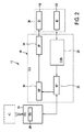
図1は、一実施形態による超音波システム10、特に医用超音波3次元イメージングシステムの概略図を示している。超音波システム10は、解剖学的部位、特に患者12の解剖学的部位、のボリュームを検査するために利用される。超音波システム10は、超音波を送信して及び/又は受け取るためのトランスデューサ素子の多数を有している少なくとも1つのトランスデューサアレイを有している超音波プローブ14を含む。一例において、トランスデューサ素子の各々は、特に複数の連続して生成される送信パルスのような、特定のパルス持続時間の少なくとも1つの送信インパルスの形で超音波を送信することができる。トランスデューサ素子は、例えば、軸回りを機械的に移動することができ又は旋回することができる2次元画像を提供するために、1次元の行で構成されることができる。更に、トランスデューサ素子は、特にマルチプラナー又は3次元画像を提供するために、2次元アレイで構成されることができる。
FIG. 1 shows a schematic diagram of an
概して、多数の2次元画像の各々が、特定の音響ライン又はスキャニングラインに沿って、特にスキャニング受信ラインに沿って、3つの異なるやり方で取得されることができる。最初に、ユーザは、手作業のスキャニングを通じて多数の画像を得ることができる。この場合、超音波プローブは、スキャンライン又はスキャン平面のロケーション及び向きを追跡することができる位置検知装置を有することもできる。しかしながら、これはここでは企図されない。第2に、トランスデューサが、超音波プローブ内で自動的且つ機械的にスキャンされることができる。これは、例えば一次元トランスデューサアレイが使用される場合に当てはまる。第3に及び好適には、トランスデューサのフェーズド2次元アレイが、超音波プローブ内に位置付けられることができ、超音波ビームが、電子的にスキャンされる。超音波プローブは、例えば医療スタッフ又は医師のようなシステムのユーザによってハンドヘルドで使用される。超音波プローブ14は、患者12の解剖学的部位の画像が供給されるように、患者12の身体に当てられる。
In general, each of a number of two-dimensional images can be acquired in three different ways along a particular acoustic line or scanning line, in particular along a scanning receive line. Initially, the user can obtain multiple images through manual scanning. In this case, the ultrasound probe can also have a position sensing device that can track the location and orientation of the scan line or scan plane. However, this is not contemplated here. Second, the transducer can be scanned automatically and mechanically within the ultrasound probe. This is the case, for example, when a one-dimensional transducer array is used. Third and preferably, a phased two-dimensional array of transducers can be positioned within the ultrasound probe, and the ultrasound beam is scanned electronically. Ultrasound probes are used handheld by users of systems such as medical staff or doctors. The
更に、超音波システム10は、超音波システム10を通じた3次元画像の供給を制御する制御ユニット16を有する。以下に記述されるように、制御ユニット16は、超音波プローブ14のトランスデューサアレイを通じたデータの取得だけでなく、信号及び画像処理をも制御し、それにより、超音波プローブ14のトランスデューサアレイによって受信される超音波ビームのエコーから3次元画像を形成する。
Furthermore, the
超音波システム10は、ユーザに3次元画像を表示するディスプレイ18を更に有する。更に、キー又はキーボード22及びトラックボール24のような他の入力装置を含みうる入力装置20が提供される。入力装置20は、ディスプレイ18に接続され、又は制御ユニット16に直接接続されることができる。
The
図2は、超音波システム10の概略ブロック図を示す。すでに上述されたように、超音波システム10は、超音波プローブ(PR)14、制御ユニット(CU)16、ディスプレイ(DI)18、及び入力装置(ID)20を有する。更に上述されたように、プローブ14は、フェーズド2次元トランスデューサアレイ26を含む。概して、制御ユニット(CU)16は、中央処理ユニット28を有することができ、中央処理ユニット28は、画像取得及び供給の全体を調整するために、アナログ及び/又はデジタル電子回路、プロセッサ、マイクロプロセッサ等を含むことができる。しかしながら、中央処理ユニット28は、超音波システム10内の別個のエンティティ又はユニットである必要はないことが理解されるべきである。中央処理ユニット28は、制御ユニット16の一部でありえ、概して、ハードウェア又はソフトウェア実現されることができる。現在の区別は説明の便宜上なされているだけである。
FIG. 2 shows a schematic block diagram of the
制御ユニット16の一部としての中央処理ユニット28は、ビームフォーマを制御することができ、これにより、ボリューム40の何の画像が取得されるか及びこれらの画像がどのように取得されるかを制御することができる。ビームフォーマ30は、トランスデューサアレイ26を駆動する電圧を決定し、それがスキャンすることができる部分繰り返し周波数を決定し、送信ビームをフォーカスし、受信又は送信ビームをアポダイズするとともに、更に、フィルタを増幅し、トランスデューサアレイ26によって返されるエコー電圧ストリームをデジタル化することができる。更に、制御ユニット16の中央処理ユニット28は、一般的なスキャニングストラテジを決定することができる。このような一般的なストラテジは、所望のボリューム取得レート、ボリュームの横方向範囲、ボリュームの仰角範囲、最大及び最小ライン密度、スキャニングライン時間及びライン密度を含むことができる。
The
ビームフォーマ30は更に、トランスデューサアレイ26から超音波信号を受け取り、それらを画像信号として送出する。
The beam former 30 further receives ultrasonic signals from the
更に、超音波システム10は、画像信号を受信する信号プロセッサ34を含む。信号プロセッサ34は概して、受信した超音波エコー又は画像信号について、アナログ−デジタル変換、デジタルフィルタリング(例えばバンドパスフィルタリング)、検出及び圧縮(例えば動的レンジの低減)を行うために提供される。信号プロセッサは、画像データを送出する。
In addition, the
更に、超音波システム10は、信号プロセッサ34から受信された画像データをディスプレイ18に最終的に表示される表示データに変換する画像プロセッサ36を含む。特に、画像プロセッサ36は、画像データを受け取り、画像データを前処理し、画像メモリにそれを記憶することができる。これらの画像データは更に、ディスプレイ18を通じてユーザに最も便利な画像を提供するために後処理される。本例において、特に、画像プロセッサ36は、取得された多数の2次元画像から3次元画像を形成することができる。
In addition, the
ユーザインタフェースは、参照数字38によって概して示されており、ディスプレイ18及び入力装置20を含む。ユーザインタフェースは更に、例えばトラックボール、マウス又は超音波プローブ14自体に提供されることさえできる他のボタンのような、他の入力装置を含むこともできる。更に、中央処理ユニット28は、入力装置20を通じてユーザによるすべてのデータ入力を受け取り、ディスプレイ18及び画像プロセッサ36を通じてユーザへの出力を制御する。それゆえ、中央処理ユニット28は更に、ユーザインタフェース38全体を制御することができる。
The user interface is generally indicated by
本発明が適応されうる3次元超音波システムの特定の例は、特に出願人のX7−2tティートランスデューサ又は出願人のxMATRIX技術を使用する別のトランスデューサとともに、出願人によって販売されているCX50 CompactXtreme超音波システムである。概して、Philips iE33システムに見られるようなマトリクストランスデューサシステム、又は例えばPhilips iU22及びHD15システムに見られるような機械的3D/4Dトランスデューサ技術に、本発明を適用することができる。 Specific examples of three-dimensional ultrasound systems to which the present invention can be applied are CX50 CompactXtreme ultrasound sold by applicants, particularly with Applicant's X7-2t tee transducer or another transducer using Applicants' xMATRIX technology. Sonic system. In general, the present invention can be applied to matrix transducer systems such as found in Philips iE33 systems, or mechanical 3D / 4D transducer technologies such as found in Philips iU22 and HD15 systems.
図3は、超音波プローブ14に対するボリューム40の一例を示す。超音波プローブ14のトランスデューサアレイは、フェーズド2次元電子スキャンアレイとして構成されるものであるので、この例で示される例示的なボリューム40は、セクタタイプであり、それゆえ、ボリューム40のサイズは、仰角42及び横方向角度44によって表現されることができる。ボリューム40の深さ46は、ライン当たり秒のいわゆるライン時間によって表現されることができる。それは、特定のスキャニングラインをスキャンするために費やされるスキャニング時間である。画像取得の最中、超音波プローブ14の2次元トランスデューサアレイが、ボリューム40が多数のスキャンラインに沿って順次にスキャンされるようにして、ビームフォーマ30によって作動される。しかしながら、マルチライン受信処理では、単一送信ビームが複数の(例えば4)の受信スキャニングラインを照査し、それらのラインに沿って、信号が平行に取得される。その場合、このような受信ラインの組が、ボリューム40全体を横切って電子的に順次にスキャンされる。
FIG. 3 shows an example of the
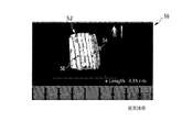
図4a及び図4bは、画像50のスクリーンショットの概略図を示す。画像50は、スキャンされたボリューム40内の構造52を示す。更に、距離の面内測定が従来技術に従って如何にして実施されるかが示されている。これらの図は、超音波イメージングシステムのための最先技術により提供されることができるボリューム40の3次元画像50の通常のスクリーンショットを提供する。
4a and 4b show a schematic diagram of a screen shot of the
3次元画像50において、構造52は、それがトランスデューサアレイ26によって取得されたデータから処理され、信号プロセッサ34及び画像プロセッサ36を通じて処理されたものとして、表示されている。構造52は、例えば血管、心臓のような患者の解剖学的部位の任意の部分でありえ、又は以下の図に示されるように波状曲面の異なる波紋でありうる。
In the three-
ユーザが、図4aの画像50を観察するときに距離を測定することを望む場合、ユーザは、第1のポイント54及び第2のポイント56を選択することができる。図4bから分かるように、ポイント54とポイント56との間で距離58は、ユーザが図4aの画像50を見るときにマークした構造52上の2つのポイント間の実際の距離に等しい。それゆえ、第1のポイント54と第2のポイント58との間のまっすぐな測定経路60は、ユーザに表示される距離58として決定される2つのポイント54、56間の実際の距離をもたらす。
If the user wishes to measure distance when viewing the
しかしながら、図5a及び図5bは、2つのポイント54及び56が図5aの画像50に示されるように同じビューイング面内にない例を示す。ユーザが、図5aの画像50の2つのポイント54及び56をマークする場合、超音波イメージングシステム10によって測定される2つのポイント54、56間の距離は、構造52上の2つのポイント54、56の間の実際の距離より短い。これは、ユーザが、図5aの画像50を見るときにマークしたかったポイントをマークしなかったことを意味する。
However, FIGS. 5a and 5b show an example where the two
これは、図5bから明白に導き出せる。図5bは、90°回転された図5aの構造を示す。面62は、図5aの画像50を観察するときにユーザに表示される面に対応する。図5bから分かるように、構造52の対応する部分は面62内にあるので、第1のポイント54が面62内にある。しかしながら、構造52は、ボリューム40にわたって延在するので、図5aの画像50を観察するときにユーザが選択した第2のポイント56は、ユーザが図5aの画像50を観察するときに選択したかった構造52上の真の第2のポイント64に対応しない。それゆえ、測定経路60に沿った、面62内の距離のみが求められるとき、2つのポイント54と56の間の求められる距離は、実際の距離より短い。しかしながら、ユーザが超音波イメージングシステム10によって算出されることを望むものは、実際の距離である。これは、「フォアショートニング効果」と呼ばれている。
This can be clearly derived from FIG. FIG. 5b shows the structure of FIG. 5a rotated 90 °.
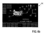
図6a及び図6bは、実施形態に従って第1のポイント54と第2のポイント56の間で距離58の面内測定を表示する。ユーザは、図6aに示されるようなボリューム40の画像50を示される。画像50は、面62内のものである。面62内で、各ポイント54、56の第1の座標66(例えばX次元)及び第2の座標68(例えばY次元)が決定されることができる。例えば、これは、画像の中及び面62の中でカーソル53を移動させることによって実施されることができる。ユーザは、構造52上でカーソル53を移動させ、測定されるべき距離58の終点のうちの1つを形成すべきである構造52のポイントを移動させることができる。従って、例えば、ユーザは、図6aに示される面62及びビューの中のカーソルを、例えば第1のポイント54の位置へ移動させる。次に、ユーザは、対応するボタンその他を打つことによって、カーソル53の位置を確認することができる。現在、図6aに示されるビューを変えずに、ユーザは、第3の次元70において適切にカーソル53を配置するために、深さ制御を与えられることができる。第3の次元70におけるカーソル53の移動は、図6aに示される画像50を観察するときユーザにとって認識できないので、視覚的インジケータ72が、ディスプレイ18上に及び画像50内に提供されることにより、カーソル53が構造52に到達したことをユーザに知らせる。図6aにおいて視覚的インジケータ72として示される感嘆符は、単なる例示的な性質のものである。他のシンボル又はフレーズが、カーソルが実際に構造52に到達する場合にのみ可視にされることができる。代替的に又は付加的に、隠れ線メカニズムにより、カーソル53は、それが構造52に入るとき消失することができる。更に、カーソル及び構造52が衝突するとき、カーソルが明るくされ、及び/又は構造52が明るくされるようにしてもよい。
6a and 6b display in-plane measurements of
面62内でカーソル53を移動させることは、「第1の移動」と呼ばれる。カーソル53を面62に対し垂直に移動させることは、「第2の移動」と呼ばれる。第1の移動及び第2の移動が続けて実施されるものとして記述されたが、これは第1及び第2の移動を実施する1つの可能性がある実施形態にすぎないことが強調されるべきである。第1及び第2の移動が同時に実施されることもできる。
Moving the
図7a及び図7bは、カーソル53の「深さ制御」が如何にしてフォアショートニング効果を回避することができるかを示す。
FIGS. 7a and 7b show how the “depth control” of the
最初に、図7a及び図7bに示されるように、カーソル53は、適切な任意の形でありうる。カーソル53は、ユーザが選択することを望みうる構造52の部分を識別するために、矢印、十字線、その他の形をもつことができる。
Initially, as shown in FIGS. 7a and 7b, the
前述したように、ユーザは、まず第1及び第2の座標66、68を決定するために面62内でカーソル53を移動させ、次いで、視覚的インジケータ72によって示されるように、カーソル53及び構造52が衝突するまで、第3の次元70においてボリューム40の深さ方向へカーソル53の第2の移動を実施することによって、図7aに示されるビューの中で第1のポイント54を選択することができる。その後、第2のポイント56が同じようにして選択されることができる。
As described above, the user first moves the
90°回転された図7bに示されるビューから分かるように、2つのポイント54、56−第2のポイント56は面62内にない−間の距離58が、適切に算出されることができる。第1のポイント54及び第2のポイント56は、構造52に到達したものとして設定されることができる。更に、このすべてが、図7aに示されるビューを変更せずに実施されることもできる。次に、第1のポイント54と第2のポイント56の間の距離58が適切に算出されることができる。
As can be seen from the view shown in FIG. 7b rotated 90 °, the
視覚的インジケータ72に加えて又は代わって、更に、オーディオインジケータ又は触覚感知インジケータが提供されることができる。図1に戻って、ディスプレイ18又は超音波イメージングシステム10の任意の他の部分は、スピーカ73を含むことができる、スピーカ73は、オーディオインジケータ74を提供するために、カーソル53が構造52と衝突する場合にノイズ又はトーンを生じるように構成されることができる。
In addition to or instead of the
更に、視覚的及びオーディオインジケータ72、74に加えて又は代わって、触覚感知インジケータ76が、例えば入力装置20に振動機構75を含めることによって、提供されることができる。これによって、ユーザは、ボリューム周辺でカーソル53を移動させるために入力装置20を使用する際に、カーソルがボリュームと衝突したときを感じることができる。
Further, in addition to or instead of the visual and
更に、超音波イメージングシステム10は、両方のポイント54、56を接続する直線に沿った最短距離としてのみならず、任意の他の測定経路78に沿った距離としても、第1のポイント54と第2のポイント56との間の距離を測定する可能性をユーザに提供するように構成されることができる。この代替の測定経路78を規定するために、ユーザは、前述したように第1の移動及び第2の移動を実施することによって、ボリューム内に他のポイント79を設定することができ、又は、第1のポイント54及び第2のポイント56を接続するために、標準の幾何学的な形(例えば楕円)を適用することができる。
In addition, the
図8は、方法80の一実施形態の概略ブロック図を示す。方法は、ステップ82において開始する。第1のステップS1において、3次元超音波画像50は、第1のポイント54及び第2のポイント56を識別するためのカーソル53と共に、ディスプレイ18に表示される。このような画像は、図6a及び図7aに示される画像のうちの1つでありうる。
FIG. 8 shows a schematic block diagram of an embodiment of method 80. The method starts at step 82. In the first step S1, the three-dimensional
次に、ステップS2において、カーソルは、第1及び第2のポイント54、56のうちの少なくとも1つの第1の座標66及び第2の座標68を識別するために、ユーザによる入力データに基づいてディスプレイ18上に提供される面と平行に移動される。
Next, in step S2, the cursor is based on input data by the user to identify at least one first coordinate 66 and second coordinate 68 of the first and
第1の座標66及び第2の座標68が規定された後、ステップS3において、カーソル53は、個々のポイントの第3の座標70を識別するために、ユーザによる入力データに基づいて、ディスプレイ上に提供される面62に垂直に移動される。
After the first coordinate 66 and the second coordinate 68 are defined, in step S3, the
ステップS3におけるこの第2の移動が実施されるとき、ステップS4において、カーソル53が構造52と衝突するかどうかが確かめられる。衝突していない場合、ディスプレイの変更は生じず、方法は、ライン86によって示されるようにループで実施される。衝突する場合、カーソル53が構造52と衝突していることの標示が与えられる。これは、前述したように視覚的標示72、オーディオ標示74又は触覚標示76でありうる。個々の標示は、ステップS5において与えられる。ここで、第3の座標70が設定されうる。これまでに1つのポイントしか規定されていない場合、方法は、更に個別の第2のポイントの座標を規定するために、矢印87によってステップS2の前に戻る。
When this second movement in step S3 is performed, it is ascertained in step S4 whether the
両方のポイントが規定された後、ステップS6において、2つのポイント54と56との間の距離58は求められる。方法は、ステップ90において終了する。
After both points are defined, the
しかしながら、ステップS2及びS3は、必ずしも続けて実施される必要はない。面内の第1の移動及び面に対し垂直な第2の移動は、破線の矢印88によって示されるように、ステップS1の直後に平行に実施されることも可能でありうる。ユーザは、すべての3つの座標66、68、70を同時に規定するためにカーソル53を移動させることができる。
However, steps S2 and S3 do not necessarily have to be performed continuously. It may also be possible that the first movement in the plane and the second movement perpendicular to the plane are performed in parallel immediately after step S1, as indicated by the dashed arrow 88. The user can move the
本発明は、図面及び上述の記述において詳細に図示され記述されているが、このような図示及び記述は、制限的でなく、説明的又は例示的なものとして考えられるべきである。本発明は、開示された実施形態に制限されない。開示された実施形態に対する他の変更が、図面、開示及び添付の請求項の検討に基づき、請求項に記載の本発明を実施する際に当業者により理解され達成されることができる。 While the invention has been illustrated and described in detail in the drawings and foregoing description, such illustration and description are to be considered illustrative or exemplary and not restrictive; The invention is not limited to the disclosed embodiments. Other modifications to the disclosed embodiments can be understood and attained by those skilled in the art in practicing the claimed invention, based on a study of the drawings, the disclosure, and the appended claims.
請求項において、「含む、有する(comprising)」という語は、他の構成要素又はステップを除外せず、不定冠詞「a」又は「an」は、複数性を除外しない。単一の構成要素又は他のユニットは、請求項に列挙されるいくつかのアイテムの機能を果たすことができる。特定の手段が相互に異なる従属請求項に列挙されているという単なる事実は、これらの手段の組み合わせが有利に使用されることができないことを示さない。 In the claims, the word “comprising” does not exclude other elements or steps, and the indefinite article “a” or “an” does not exclude a plurality. A single component or other unit may fulfill the functions of several items recited in the claims. The mere fact that certain measures are recited in mutually different dependent claims does not indicate that a combination of these measured cannot be used to advantage.
コンピュータプログラムは、例えば、他のハードウェアと共に又はその一部として供給される光学記憶媒体又はソリッドステート媒体のような適切な媒体に記憶され/配布されることができるが、インターネット又は他のワイヤード若しくはワイヤレスの通信システムを通じて他の形式でも配布されることができる。 The computer program can be stored / distributed on a suitable medium such as an optical storage medium or solid state medium supplied with or as part of other hardware, for example, the Internet or other wired or Other formats can also be distributed through the wireless communication system.
請求項における任意の参照符号は、本発明の範囲を制限するものとして解釈されるべきでない。 Any reference signs in the claims should not be construed as limiting the scope of the invention.
Claims (14)
超音波受信信号を供給するトランスデューサアレイと、
前記超音波受信信号を受け取り、3次元画像を表現する表示データを供給する制御ユニットであって、前記3次元画像において識別される第1のポイントと第2のポイントとの間の距離を算出するようにも構成される制御ユニットと、
前記表示データを受け取り、前記ボリュームと、前記第1のポイント及び前記第2のポイントを識別するためのカーソルと、の3次元画像を提供するディスプレイと、
前記カーソルの移動を含む入力データを、前記制御ユニットに供給する入力装置と、
を有し、
前記超音波イメージングシステムは、前記ディスプレイに提供される前記3次元画像をビューする際にユーザに示される面内における前記カーソルの第1の移動、及び前記カーソルの、前記面に対し垂直な方向への第2の移動を可能にするように構成され、
前記超音波イメージングシステムは更に、前記カーソルが前記ボリューム内の構造と衝突する場合に標示を提供する、超音波イメージングシステム。 An ultrasound imaging system that provides a three-dimensional image of a volume,
A transducer array for supplying ultrasonic reception signals;
A control unit that receives the ultrasonic reception signal and supplies display data representing a three-dimensional image, and calculates a distance between a first point and a second point identified in the three-dimensional image A control unit also configured to,
A display that receives the display data and provides a three-dimensional image of the volume and a cursor for identifying the first point and the second point;
An input device for supplying input data including movement of the cursor to the control unit;
Have
The ultrasound imaging system includes a first movement of the cursor in a plane shown to a user when viewing the three-dimensional image provided on the display, and a direction of the cursor perpendicular to the plane. Configured to allow a second movement of
The ultrasound imaging system further provides an indication when the cursor collides with a structure in the volume .
前記画像信号を受け取り、画像データを供給する信号プロセッサと、
前記信号プロセッサから前記画像データを受け取り、表示データを供給する画像プロセッサと、
を更に有する、請求項1に記載の超音波イメージングシステム。 A beamformer that controls the transducer array to scan the volume along a plurality of scanning lines, the beamformer further configured to receive an ultrasound received signal and provide an image signal;
A signal processor for receiving the image signal and supplying image data;
An image processor that receives the image data from the signal processor and provides display data;
The ultrasound imaging system of claim 1, further comprising:
ディスプレイ上に、前記3次元超音波画像を、前記第1のポイント及び前記第2のポイントを識別するためのカーソルとともに表示するステップと、
前記第1及び前記第2のポイントのうち少なくとも一方の第1の座標及び第2の座標を識別するために、入力データに基づいて、前記ディスプレイ上に提供される前記3次元超音波画像をビューする際にユーザに示される面と平行にカーソルを移動させるステップと、
個々のポイントの第3の座標を識別するために、入力データに基づいて、前記ディスプレイ上に提供された面に対し前記カーソルを垂直に移動させるステップと、
前記カーソルが前記ボリューム内に表示された構造と衝突する場合に標示を提供するステップと、
前記第1のポイントと前記第2のポイントとの間の距離を算出するステップと、
を含む方法。 A method for calculating a distance between a first point and a second point in a three-dimensional ultrasound image of a volume, comprising:
Displaying the three-dimensional ultrasound image on a display together with a cursor for identifying the first point and the second point;
View the three-dimensional ultrasound image provided on the display based on input data to identify first and second coordinates of at least one of the first and second points. Moving the cursor parallel to the plane shown to the user when doing
Moving the cursor perpendicular to a surface provided on the display based on input data to identify third coordinates of individual points;
Providing an indication when the cursor collides with a structure displayed in the volume;
Calculating a distance between the first point and the second point;
Including methods.
Applications Claiming Priority (3)
| Application Number | Priority Date | Filing Date | Title |
|---|---|---|---|
| US201261663652P | 2012-06-25 | 2012-06-25 | |
| US61/663,652 | 2012-06-25 | ||
| PCT/IB2013/054962 WO2014001954A1 (en) | 2012-06-25 | 2013-06-17 | System and method for 3d ultrasound volume measurements |
Publications (3)
| Publication Number | Publication Date |
|---|---|
| JP2015519990A JP2015519990A (en) | 2015-07-16 |
| JP2015519990A5 JP2015519990A5 (en) | 2016-08-04 |
| JP6114822B2 true JP6114822B2 (en) | 2017-04-12 |
Family
ID=49035618
Family Applications (1)
| Application Number | Title | Priority Date | Filing Date |
|---|---|---|---|
| JP2015517899A Active JP6114822B2 (en) | 2012-06-25 | 2013-06-17 | System and method for 3D ultrasonic volume measurement |
Country Status (7)
| Country | Link |
|---|---|
| US (1) | US10335120B2 (en) |
| EP (1) | EP2864807B1 (en) |
| JP (1) | JP6114822B2 (en) |
| CN (1) | CN104412123B (en) |
| BR (1) | BR112014032020B1 (en) |
| RU (1) | RU2620865C2 (en) |
| WO (1) | WO2014001954A1 (en) |
Families Citing this family (4)
| Publication number | Priority date | Publication date | Assignee | Title |
|---|---|---|---|---|
| US20180052589A1 (en) * | 2016-08-16 | 2018-02-22 | Hewlett Packard Enterprise Development Lp | User interface with tag in focus |
| US10355120B2 (en) * | 2017-01-18 | 2019-07-16 | QROMIS, Inc. | Gallium nitride epitaxial structures for power devices |
| EP3378405A1 (en) * | 2017-03-20 | 2018-09-26 | Koninklijke Philips N.V. | Volume rendered ultrasound imaging |
| EP3561656A1 (en) * | 2018-04-23 | 2019-10-30 | Koninklijke Philips N.V. | Precise positioning of a marker on a display |
Family Cites Families (18)
| Publication number | Priority date | Publication date | Assignee | Title |
|---|---|---|---|---|
| US5920319A (en) * | 1994-10-27 | 1999-07-06 | Wake Forest University | Automatic analysis in virtual endoscopy |
| JP3015728B2 (en) * | 1996-05-21 | 2000-03-06 | アロカ株式会社 | Ultrasound diagnostic equipment |
| JPH10201755A (en) * | 1997-01-24 | 1998-08-04 | Hitachi Medical Corp | Method for measuring three-dimensional size in pseudo-three-dimensional image and its system |
| JP3325224B2 (en) * | 1998-04-15 | 2002-09-17 | オリンパス光学工業株式会社 | Ultrasound image diagnostic equipment |
| US6048314A (en) | 1998-09-18 | 2000-04-11 | Hewlett-Packard Company | Automated measurement and analysis of patient anatomy based on image recognition |
| JP4558904B2 (en) * | 2000-08-17 | 2010-10-06 | アロカ株式会社 | Image processing apparatus and storage medium |
| US7674228B2 (en) * | 2004-03-01 | 2010-03-09 | Sunnybrook And Women's College Health Sciences Centre | System and method for ECG-triggered retrospective color flow ultrasound imaging |
| US20080262351A1 (en) * | 2004-09-30 | 2008-10-23 | Koninklijke Philips Electronics, N.V. | Microbeamforming Transducer Architecture |
| JP2006314518A (en) * | 2005-05-12 | 2006-11-24 | Toshiba Corp | Ultrasonic diagnostic unit |
| JP4740695B2 (en) * | 2005-08-26 | 2011-08-03 | 株式会社日立メディコ | Ultrasonic diagnostic equipment |
| WO2010018512A1 (en) * | 2008-08-12 | 2010-02-18 | Koninklijke Philips Electronics N.V. | Ultrasound imaging |
| EP2182352A3 (en) | 2008-10-29 | 2011-08-03 | Hitachi Ltd. | Apparatus and method for ultrasonic testing |
| KR101121301B1 (en) | 2009-09-16 | 2012-03-22 | 삼성메디슨 주식회사 | Ultrasound system and method of performing 3-dimensional measurement |
| US8819591B2 (en) * | 2009-10-30 | 2014-08-26 | Accuray Incorporated | Treatment planning in a virtual environment |
| KR101175426B1 (en) | 2010-01-26 | 2012-08-20 | 삼성메디슨 주식회사 | Ultrasound system and method for providing three-dimensional ultrasound image |
| JP2011215692A (en) * | 2010-03-31 | 2011-10-27 | Hokkaido Univ | Three-dimensional three-degree-of-freedom rotation parameter processor |
| JP5535725B2 (en) * | 2010-03-31 | 2014-07-02 | 富士フイルム株式会社 | Endoscope observation support system, endoscope observation support device, operation method thereof, and program |
| US9047394B2 (en) * | 2010-10-22 | 2015-06-02 | Samsung Medison Co., Ltd. | 3D ultrasound system for intuitive displaying to check abnormality of object and method for operating 3D ultrasound system |
-
2013
- 2013-06-17 EP EP13753208.1A patent/EP2864807B1/en active Active
- 2013-06-17 US US14/406,760 patent/US10335120B2/en active Active
- 2013-06-17 JP JP2015517899A patent/JP6114822B2/en active Active
- 2013-06-17 BR BR112014032020-9A patent/BR112014032020B1/en not_active IP Right Cessation
- 2013-06-17 CN CN201380033938.7A patent/CN104412123B/en active Active
- 2013-06-17 WO PCT/IB2013/054962 patent/WO2014001954A1/en active Application Filing
- 2013-06-17 RU RU2015102094A patent/RU2620865C2/en active
Also Published As
| Publication number | Publication date |
|---|---|
| BR112014032020A2 (en) | 2017-06-27 |
| CN104412123B (en) | 2017-05-17 |
| US20150157297A1 (en) | 2015-06-11 |
| RU2015102094A (en) | 2016-08-20 |
| EP2864807A1 (en) | 2015-04-29 |
| EP2864807B1 (en) | 2021-05-26 |
| WO2014001954A1 (en) | 2014-01-03 |
| BR112014032020A8 (en) | 2021-03-16 |
| JP2015519990A (en) | 2015-07-16 |
| RU2620865C2 (en) | 2017-05-30 |
| BR112014032020B1 (en) | 2023-02-23 |
| US10335120B2 (en) | 2019-07-02 |
| CN104412123A (en) | 2015-03-11 |
Similar Documents
| Publication | Publication Date | Title |
|---|---|---|
| EP3013243B1 (en) | Elastography measurement system and method | |
| CN108784735B (en) | Ultrasound imaging system and method for displaying acquisition quality level | |
| KR101495528B1 (en) | Ultrasound system and method for providing direction information of a target object | |
| JP5702922B2 (en) | An ultrasound system for visualizing an ultrasound probe on an object | |
| US9084556B2 (en) | Apparatus for indicating locus of an ultrasonic probe, ultrasonic diagnostic apparatus | |
| KR101182880B1 (en) | Ultrasound system and method for providing image indicator | |
| US10588595B2 (en) | Object-pose-based initialization of an ultrasound beamformer | |
| CN105518482B (en) | Ultrasonic imaging instrument visualization | |
| CN107072635B (en) | Quality metric for multi-hop echocardiography acquisition for intermediate user feedback | |
| US20160000399A1 (en) | Method and apparatus for ultrasound needle guidance | |
| US20110201935A1 (en) | 3-d ultrasound imaging | |
| US11793483B2 (en) | Target probe placement for lung ultrasound | |
| JP7022217B2 (en) | Echo window artifact classification and visual indicators for ultrasound systems | |
| JP5743329B2 (en) | Ultrasonic diagnostic apparatus and control program therefor | |
| US20110066031A1 (en) | Ultrasound system and method of performing measurement on three-dimensional ultrasound image | |
| JP6114822B2 (en) | System and method for 3D ultrasonic volume measurement | |
| CN109069121A (en) | Positioning support and fetal heart frequency registration for CTG ultrasonic transducer are supported | |
| CN102415902A (en) | Ultrasonic diagnostic apparatus and ultrasonic image processng apparatus | |
| CN109923432A (en) | Utilize the system and method for the feedback and tracking intervention instrument about tracking reliability | |
| JP2004057379A (en) | Ultrasonic diagnostic system | |
| JP6865695B2 (en) | Ultrasound imaging device | |
| US20140330125A1 (en) | Large volume three-dimensional ultrsaound imaging | |
| WO2015099835A1 (en) | System and method for displaying ultrasound images | |
| US20210196237A1 (en) | Methods and apparatuses for modifying the location of an ultrasound imaging plane | |
| JP2006288964A (en) | Ultrasonic diagnostic equipment |
Legal Events
| Date | Code | Title | Description |
|---|---|---|---|
| A521 | Request for written amendment filed |
Free format text: JAPANESE INTERMEDIATE CODE: A523 Effective date: 20160614 |
|
| A621 | Written request for application examination |
Free format text: JAPANESE INTERMEDIATE CODE: A621 Effective date: 20160614 |
|
| RD04 | Notification of resignation of power of attorney |
Free format text: JAPANESE INTERMEDIATE CODE: A7424 Effective date: 20170214 |
|
| TRDD | Decision of grant or rejection written | ||
| A01 | Written decision to grant a patent or to grant a registration (utility model) |
Free format text: JAPANESE INTERMEDIATE CODE: A01 Effective date: 20170228 |
|
| A977 | Report on retrieval |
Free format text: JAPANESE INTERMEDIATE CODE: A971007 Effective date: 20170228 |
|
| A61 | First payment of annual fees (during grant procedure) |
Free format text: JAPANESE INTERMEDIATE CODE: A61 Effective date: 20170317 |
|
| R150 | Certificate of patent or registration of utility model |
Ref document number: 6114822 Country of ref document: JP Free format text: JAPANESE INTERMEDIATE CODE: R150 |
|
| R250 | Receipt of annual fees |
Free format text: JAPANESE INTERMEDIATE CODE: R250 |
|
| R250 | Receipt of annual fees |
Free format text: JAPANESE INTERMEDIATE CODE: R250 |
|
| R250 | Receipt of annual fees |
Free format text: JAPANESE INTERMEDIATE CODE: R250 |
|
| R250 | Receipt of annual fees |
Free format text: JAPANESE INTERMEDIATE CODE: R250 |
|
| R250 | Receipt of annual fees |
Free format text: JAPANESE INTERMEDIATE CODE: R250 |