JP6111663B2 - Air conditioner - Google Patents
Air conditioner Download PDFInfo
- Publication number
- JP6111663B2 JP6111663B2 JP2012288805A JP2012288805A JP6111663B2 JP 6111663 B2 JP6111663 B2 JP 6111663B2 JP 2012288805 A JP2012288805 A JP 2012288805A JP 2012288805 A JP2012288805 A JP 2012288805A JP 6111663 B2 JP6111663 B2 JP 6111663B2
- Authority
- JP
- Japan
- Prior art keywords
- refrigerant
- gas
- indoor
- outdoor
- valve
- Prior art date
- Legal status (The legal status is an assumption and is not a legal conclusion. Google has not performed a legal analysis and makes no representation as to the accuracy of the status listed.)
- Active
Links
Images


Landscapes
- Compression-Type Refrigeration Machines With Reversible Cycles (AREA)
Description
本発明は、複数の室内熱交換器を有する空気調和装置に関し、特に、冷房と暖房が混在する運転を行えるように構成された空気調和装置に関するものである。 The present invention relates to an air conditioner having a plurality of indoor heat exchangers, and more particularly to an air conditioner configured to perform an operation in which cooling and heating are mixed.
従来より、冷媒回路で冷凍サイクル行い室内を空調する空気調和装置が知られている。この種の空気調和装置として、複数の室内熱交換器を有し冷房と暖房とを同時に行う、いわゆる冷暖フリー型の空気調和装置が知られている。 2. Description of the Related Art Conventionally, an air conditioner that performs a refrigeration cycle in a refrigerant circuit and air-conditions a room is known. As this type of air conditioner, a so-called cooling / heating-free type air conditioner having a plurality of indoor heat exchangers that simultaneously performs cooling and heating is known.
特許文献1には、この種の空気調和装置が開示されている。この空気調和装置では、室外熱交換器を有する室外ユニットと、気液分離器及び切換回路を有する切換ユニット(中継器)と、複数の室内ユニットとが配管により接続され、冷媒回路が構成されている。空気調和装置では、切換ユニットの流路が切り換えられることで、全冷房運転と、冷房主体運転と、全暖房運転と、暖房主体運転とが切り換えて行われる。
冷房主体運転は、全体の冷房負荷が暖房負荷よりも大きい条件で行われる。この運転では、圧縮機で圧縮された高圧のガス冷媒が、室外熱交換器で放熱(凝縮)した後、気液分離器に流入する。気液分離器では、気液二相状態の冷媒がガス冷媒と液冷媒とに分離する。ガス冷媒は、暖房側の室内熱交換器へ送られ、室内空気へ放熱する。この結果、室内の暖房が行われる。一方、液冷媒は、膨張弁で減圧された後、冷房側の室内熱交換器へ送られる。この結果、室内の冷房が行われる。このように、冷房主体運転では、気液分離器で分離したガス冷媒と液冷媒とを各室内熱交換器へ送ることで、冷房と暖房とを同時に行っている。 The cooling main operation is performed under the condition that the entire cooling load is larger than the heating load. In this operation, the high-pressure gas refrigerant compressed by the compressor radiates heat (condenses) by the outdoor heat exchanger and then flows into the gas-liquid separator. In the gas-liquid separator, the gas-liquid two-phase refrigerant is separated into a gas refrigerant and a liquid refrigerant. The gas refrigerant is sent to the indoor heat exchanger on the heating side and radiates heat to the indoor air. As a result, the room is heated. On the other hand, the liquid refrigerant is depressurized by the expansion valve and then sent to the indoor heat exchanger on the cooling side. As a result, the room is cooled. Thus, in the cooling main operation, cooling and heating are performed simultaneously by sending the gas refrigerant and the liquid refrigerant separated by the gas-liquid separator to each indoor heat exchanger.
上述した冷房主体運転では、冷房負荷と暖房負荷の比率に応じて、暖房側の室内熱交換器へ送るガス冷媒の最適な総流量、及び冷房側の室内熱交換器へ送る液冷媒の最適な総流量とが変化することになる。このため、冷房負荷と暖房負荷の比率に応じて、気液分離器へ供給する気液二相冷媒の乾き度を調節し、各室内熱交換器へ送るガス冷媒の流量と、液冷媒の流量を最適に制御することが考えられる。具体的には、例えば室外熱交換器を多数のパスに分割し、各パスを流れる冷媒の流路を開閉弁等で多段階に切り換えることで、冷媒の放熱量を調節し、気液分離器へ供給する冷媒の乾き度を多段階に調節することができる。しかし、この構成では、気液二相冷媒の乾き度を細かく制御すればするほど、室外熱交換器の構造が複雑となり、コストの増大に繋がってしまう。 In the cooling-main operation described above, the optimum total flow rate of the gas refrigerant to be sent to the heating-side indoor heat exchanger and the optimum liquid refrigerant to be sent to the cooling-side indoor heat exchanger according to the ratio of the cooling load to the heating load. The total flow rate will change. Therefore, the flow rate of the gas refrigerant sent to each indoor heat exchanger and the flow rate of the liquid refrigerant are adjusted by adjusting the dryness of the gas-liquid two-phase refrigerant supplied to the gas-liquid separator according to the ratio between the cooling load and the heating load. It is conceivable to optimally control. Specifically, for example, the outdoor heat exchanger is divided into a large number of paths, and the refrigerant flow through each path is switched in multiple stages with an on-off valve or the like to adjust the heat release amount of the refrigerant, and the gas-liquid separator The dryness of the refrigerant to be supplied to can be adjusted in multiple stages. However, in this configuration, the more finely controlled the dryness of the gas-liquid two-phase refrigerant, the more complicated the structure of the outdoor heat exchanger, leading to an increase in cost.
本発明は、かかる点に鑑みてなされたものであり、その目的は、冷房と暖房とを同時に行う運転において、シンプルな構成により、気液分離器へ供給する冷媒の乾き度を調節できる空気調和装置を提供することである。 The present invention has been made in view of the above points, and an object thereof is air conditioning in which the dryness of the refrigerant supplied to the gas-liquid separator can be adjusted with a simple configuration in an operation in which cooling and heating are performed simultaneously. Is to provide a device.
第1の発明は、圧縮機(21)と、室外熱交換器(22)と、気液分離器(41)と、複数の室内熱交換器(71)とが接続された冷媒回路(20)を備え、該冷媒回路(20)では、上記気液分離器(41)で分離したガス冷媒を一部の室内熱交換器(71)で放熱させると同時に該気液分離器(41)で分離した液冷媒を一部の室内熱交換器(71)で蒸発させ、暖房と冷房とを同時に行う冷凍サイクルが可能に構成された冷媒回路(20)を備えた空気調和装置を対象とし、上記圧縮機(21)から吐出された高圧ガス冷媒の一部を上記室外熱交換器(22)の液側端部と上記気液分離器(41)の流入端部の間にバイパスさせるバイパス回路(18,31)と、室外熱交換器(22)を流出する冷媒の流量に対する上記バイパス回路(18,31)を流出する冷媒の流量の比率を調節する調節機構(35)と、冷媒の流路を開閉する開閉機構(35)を有し、上記圧縮機(21)の吐出側と第1の連絡配管(11)とを連通させ且つ該圧縮機(21)の吸入側と第2の連絡配管(12)とを連通させる第1の状態と、上記圧縮機(21)の吐出側と該第2の連絡配管(12)とを連通させ且つ上記圧縮機(21)の吸入側と上記第1の連絡配管(11)とを連通させる第2の状態とに切り換える切換回路(25)とを備え、上記調節機構(35)が、上記切換回路(25)の開閉機構を兼用していることを特徴とする。 The first invention is a refrigerant circuit (20) in which a compressor (21), an outdoor heat exchanger (22), a gas-liquid separator (41), and a plurality of indoor heat exchangers (71) are connected. In the refrigerant circuit (20), the gas refrigerant separated by the gas-liquid separator (41) is radiated by some indoor heat exchangers (71) and simultaneously separated by the gas-liquid separator (41). The above-mentioned compression is applied to an air conditioner equipped with a refrigerant circuit (20) configured to evaporate the liquefied liquid refrigerant in some indoor heat exchangers (71) and enable a refrigeration cycle to perform heating and cooling simultaneously. A bypass circuit (18 for bypassing a part of the high-pressure gas refrigerant discharged from the machine (21) between the liquid side end of the outdoor heat exchanger (22) and the inflow end of the gas-liquid separator (41) , 31) and adjustment to adjust the ratio of the flow rate of refrigerant flowing out of the bypass circuit (18, 31) to the flow rate of refrigerant flowing out of the outdoor heat exchanger (22) A mechanism ( 35 ) and an opening / closing mechanism (35) for opening and closing the refrigerant flow path, communicating the discharge side of the compressor (21) with the first connecting pipe (11), and the compressor (21 ) And the second communication pipe (12), the discharge side of the compressor (21) and the second communication pipe (12) are communicated, and the compressor A switching circuit (25) for switching between the suction side of (21) and the first communication pipe (11), and the adjustment mechanism (35) includes the switching circuit (25). The opening / closing mechanism is also used .
第1の発明では、圧縮機(21)で圧縮された冷媒が、室外熱交換器(22)で放熱した後、気液分離器(41)へ流入する。気液分離器(41)では、冷媒がガス冷媒と液冷媒とに分離する。ガス冷媒は、複数の室内熱交換器(71)のうちの一部へ供給され、室内空気へ放熱する。この結果、室内の暖房が行われる。液冷媒は、複数の室内熱交換器(71)のうちの一部へ供給され、室内空気から吸熱して蒸発する。この結果、室内の冷房が行われる。 In the first invention, the refrigerant compressed by the compressor (21) radiates heat in the outdoor heat exchanger (22) and then flows into the gas-liquid separator (41). In the gas-liquid separator (41), the refrigerant is separated into a gas refrigerant and a liquid refrigerant. The gas refrigerant is supplied to some of the plurality of indoor heat exchangers (71) and radiates heat to the room air. As a result, the room is heated. The liquid refrigerant is supplied to a part of the plurality of indoor heat exchangers (71) and absorbs heat from the indoor air to evaporate. As a result, the room is cooled.
このような運転において、気液分離器(41)へ供給される冷媒の乾き度が調節機構(35)によって調節される。つまり、冷媒回路(20)には、圧縮機(21)から吐出された高圧ガス冷媒の一部が、室外熱交換器(22)をバイパスするバイパス回路(18,31)が設けられる。このため、冷媒回路(20)では、室外熱交換器(22)で放熱した冷媒と、バイパス回路(18,31)を通過したガス冷媒とが、気液分離器(41)の流入側で混合する。そして、調節機構(35)は、室外熱交換器(22)を流出する冷媒の流量に対するバイパス回路(18,31)を流出する冷媒の流量の比率を調節する。この結果、気液分離器(41)へ供給される冷媒の乾き度が調節可能となる。 In such operation, the dryness of the refrigerant supplied to the gas-liquid separator (41) is adjusted by the adjusting mechanism ( 35 ). That is, the refrigerant circuit (20) is provided with a bypass circuit (18, 31) in which a part of the high-pressure gas refrigerant discharged from the compressor (21) bypasses the outdoor heat exchanger (22). For this reason, in the refrigerant circuit (20), the refrigerant radiated by the outdoor heat exchanger (22) and the gas refrigerant passed through the bypass circuit (18, 31) are mixed on the inflow side of the gas-liquid separator (41). To do. The adjusting mechanism ( 35 ) adjusts the ratio of the flow rate of the refrigerant flowing out of the bypass circuit (18, 31) to the flow rate of the refrigerant flowing out of the outdoor heat exchanger (22). As a result, the dryness of the refrigerant supplied to the gas-liquid separator (41) can be adjusted.
第2の発明は、第1の発明において、調節機構(35)は、上記複数の室内熱交換器(71)の全体の冷房負荷に対する全体の暖房負荷の比が大きくなるにつれて、上記比率を大きくするように構成されることを特徴とする。 In a second aspect based on the first aspect, the adjusting mechanism ( 35 ) increases the ratio as the ratio of the overall heating load to the overall cooling load of the plurality of indoor heat exchangers (71) increases. It is comprised so that it may do.
第2の発明では、空気調和装置の全体の空調負荷のうち暖房負荷の比率が大きくなるほど、室外熱交換器(22)で放熱した冷媒の流量に対するバイパス回路(18,31)の冷媒の流量の比率が大きくなる。この結果、気液分離器(41)の流入側で混合した後の冷媒の乾き度が大きくなる。従って、気液分離器(41)では、液冷媒に対するガス冷媒の比率も大きくなり、暖房負荷に見合ったガス冷媒を室内熱交換器(71)へ供給できる。 In the second invention, as the ratio of the heating load to the entire air conditioning load of the air conditioner increases, the flow rate of the refrigerant in the bypass circuit (18, 31) with respect to the flow rate of the refrigerant radiated by the outdoor heat exchanger (22) is reduced. The ratio increases. As a result, the dryness of the refrigerant after mixing on the inflow side of the gas-liquid separator (41) increases. Therefore, in the gas-liquid separator (41), the ratio of the gas refrigerant to the liquid refrigerant is increased, and the gas refrigerant commensurate with the heating load can be supplied to the indoor heat exchanger (71).
第3の発明は、第1又は第2の発明において、上記冷媒回路(20)は、上記室外熱交換器(22)で室外空気へ放熱した後の冷媒が液冷媒となるように構成されることを特徴とする。 According to a third invention, in the first or second invention, the refrigerant circuit (20) is configured such that the refrigerant after radiating heat to the outdoor air by the outdoor heat exchanger (22) becomes a liquid refrigerant. It is characterized by that.
第3の発明では、室外熱交換器(22)で放熱した後の冷媒が液冷媒となるように、冷凍サイクルが行われる。つまり、気液分離器(41)の流入側では、バイパス回路(18,31)を流出するガス冷媒と、室外熱交換器(22)を流出する液冷媒とが混合する。このようにすると、室外熱交換器(22)を流出する冷媒が気液二相状態である場合と比較して、混合した後の冷媒の乾き度を容易に推定できる。従って、気液分離器(41)へ供給される冷媒の乾き度を精度良く調節できる。 In 3rd invention, a refrigerating cycle is performed so that the refrigerant | coolant after thermally radiating with an outdoor heat exchanger (22) turns into a liquid refrigerant. That is, on the inflow side of the gas-liquid separator (41), the gas refrigerant flowing out of the bypass circuit (18, 31) and the liquid refrigerant flowing out of the outdoor heat exchanger (22) are mixed. In this way, compared with the case where the refrigerant flowing out of the outdoor heat exchanger (22) is in a gas-liquid two-phase state, it is possible to easily estimate the dryness of the refrigerant after mixing. Therefore, the dryness of the refrigerant supplied to the gas-liquid separator (41) can be accurately adjusted.
第4の発明は、第1乃至第3のいずれか1つの発明において、上記圧縮機(21)及び室外熱交換器(22)が接続される室外回路(20a)を有する室外ユニット(2)と、上記気液分離器(41)が接続される中継回路(20c,20e)を有する気液分離ユニット(4,6)と、上記室外回路(20a)と中継回路(20c,20e)とを接続する2本の連絡配管(11,12)とを備えていることを特徴とする。 According to a fourth invention, in any one of the first to third inventions, an outdoor unit (2) having an outdoor circuit (20a) to which the compressor (21) and the outdoor heat exchanger (22) are connected; The gas-liquid separation unit (4, 6) having the relay circuit (20c, 20e) to which the gas-liquid separator (41) is connected is connected to the outdoor circuit (20a) and the relay circuit (20c, 20e). And two connecting pipes (11, 12).
第4の発明では、室外ユニット(2)と気液分離ユニット(4,6)とが2本の連絡配管(11,12)によって連結される。 In the fourth invention, the outdoor unit (2) and the gas-liquid separation unit (4, 6) are connected by the two connecting pipes (11, 12).
第5の発明は、第4の発明において、上記中継回路(20c,20e)には、上記室内熱交換器(71)における液冷媒とガス冷媒の流れを切り換えるための切換機構(63,64,83,84,85)が接続されていることを特徴とする。 According to a fifth invention, in the fourth invention, the relay circuit (20c, 20e) is provided with a switching mechanism (63, 64, 20e) for switching the flow of liquid refrigerant and gas refrigerant in the indoor heat exchanger (71). 83, 84, 85) are connected.
第5の発明では、気液分離ユニット(4,6)の中継回路(20c,20e)に切換機構(63,64,83,84,85)と気液分離器(41)と接続される。 In the fifth invention, the switching mechanism (63, 64, 83, 84, 85) and the gas-liquid separator (41) are connected to the relay circuit (20c, 20e) of the gas-liquid separation unit (4, 6).
第6の発明は、第1乃至第5のいずれか1つの発明において、冷媒回路(20)の冷媒がジフオロメタンであることを特徴とする。 A sixth invention is characterized in that, in any one of the first to fifth inventions, the refrigerant in the refrigerant circuit (20) is difluoromethane.
第6の発明では、冷媒回路(20)において、ジフオロメタンを用いた冷凍サイクルが行われる。 In the sixth invention, a refrigeration cycle using difluoromethane is performed in the refrigerant circuit (20).
本発明によれば、室外熱交換器(22)で放熱した冷媒の流量と、バイパス回路(18,31)を流出した冷媒の流量との比率を調節機構(35)によって調節するため、気液分離器(41)へ供給される冷媒の乾き度を調節できる。この結果、気液分離器(41)で分離されるガス冷媒と液冷媒の割合を容易に変更でき、暖房側の室内熱交換器(71)と冷房側の室内熱交換器(71)とに最適な流量の冷媒を供給できる。また、本発明は、バイパス回路(18,31)と調節機構(35)とが設けられるだけであり、室外熱交換器(22)の構造が複雑とならない。このため、空気調和装置の簡素化、コストの低減を図ることができる。更に、本発明では、バイパス回路(18,31)の冷媒の流量を制御することで、気液分離器(41)へ供給される冷媒の乾き度をきめ細かく調節できる。 According to the present invention, the ratio of the flow rate of the refrigerant radiated by the outdoor heat exchanger (22) and the flow rate of the refrigerant that has flowed out of the bypass circuit (18, 31) is adjusted by the adjustment mechanism ( 35 ). The dryness of the refrigerant supplied to the separator (41) can be adjusted. As a result, the ratio of the gas refrigerant to the liquid refrigerant separated by the gas-liquid separator (41) can be easily changed, and the heating-side indoor heat exchanger (71) and the cooling-side indoor heat exchanger (71) can be changed. An optimal flow rate of refrigerant can be supplied. In the present invention, only the bypass circuit (18, 31) and the adjusting mechanism ( 35 ) are provided, and the structure of the outdoor heat exchanger (22) is not complicated. For this reason, simplification of an air conditioning apparatus and reduction of cost can be aimed at. Furthermore, in the present invention, the degree of dryness of the refrigerant supplied to the gas-liquid separator (41) can be finely adjusted by controlling the flow rate of the refrigerant in the bypass circuit (18, 31).
第2の発明では、冷房負荷と暖房負荷の比率に応じて、最適な流量のガス冷媒、及び液冷媒を供給できる。また、第3の発明では、気液分離器(41)へ供給される冷媒の乾き度を精度良く調節できる。 In the second aspect of the invention, it is possible to supply gas refrigerant and liquid refrigerant having optimum flow rates in accordance with the ratio between the cooling load and the heating load. In the third invention, the dryness of the refrigerant supplied to the gas-liquid separator (41) can be accurately adjusted.
第4の発明では、室外ユニット(2)と気液分離ユニット(4,6)とが2本の連絡配管(11,12)で接続されるため、3本の方式と比較して、装置構造を簡素化でき、施工も容易となる。また、2本の連絡配管を有する既存のビル用マルチ式の空気調和装置に対し、本発明に係る気液分離ユニットを取り付けることで、この空気調和装置に冷暖フリー式の機能を付与することができる。また、第6の発明では、ジフルオロメタンを用いた空気調和装置において、暖房側の室内熱交換器(71)と冷房側の室内熱交換器(71)とに最適な流量の冷媒を供給できる。 In the fourth aspect of the invention, the outdoor unit (2) and the gas-liquid separation unit (4, 6) are connected by two connecting pipes (11, 12). Can be simplified and construction is also easy. In addition, by attaching the gas-liquid separation unit according to the present invention to an existing building multi-type air conditioner having two connecting pipes, it is possible to impart a cooling / heating-free function to the air conditioner. it can. In the sixth aspect of the invention, in the air conditioner using difluoromethane, it is possible to supply an optimal flow rate of refrigerant to the heating-side indoor heat exchanger (71) and the cooling-side indoor heat exchanger (71).
以下、本発明の実施形態を図面に基づいて詳細に説明する。なお、以下の実施形態は、本質的に好ましい例示であって、本発明、その適用物、あるいはその用途の範囲を制限することを意図するものではない。 Hereinafter, embodiments of the present invention will be described in detail with reference to the drawings. The following embodiments are essentially preferable examples, and are not intended to limit the scope of the present invention, its application, or its use.
《発明の実施形態1》
実施形態1は、室外ユニットに対して並列に接続された複数の室内ユニットを有し、冷房と暖房が混在する運転が可能に構成されたいわゆる冷暖フリー型の空気調和装置に関するものである。この空気調和装置は、冷房と暖房とを混在させずに切り換えて行う室内マルチタイプの既設の空気調和装置を、冷暖フリー型の空気調和装置に更新するのに適した構成を備えている。以下の説明において、更新前の装置の冷媒回路には旧冷媒としてR410A又はR22が充填され、更新後の装置の冷媒回路には新冷媒としてR32(ジフルオロメタン)が充填されるものとする。
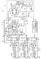
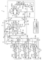
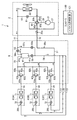
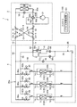
図1に示すように、この空気調和装置(1)は、室外ユニット(2)と、複数(図では3台)の室内ユニット(3)と、気液分離器を有する気液分離ユニット(4)と、室内ユニット(3)と同数の運転切換ユニット(5)とを有している。室外ユニット(2)には室外回路(20a)が、各室内ユニット(3)には室内回路(20b)が、気液分離ユニット(4)には第1中継回路(20c)が、各運転切換ユニット(5)には第2中継回路(20d)がそれぞれ接続されている。室外回路(20a)と第1中継回路(20c)とは、2本の室外部連絡配管(11,12)を介して互いに接続されている。各第2中継回路(20d)は、3本の中間部連絡配管(15,16,17)を介して第1中継回路(20c)に並列に接続されている。各室内回路(20b)は、2本の室内部連絡配管(13,14)を介して各第2中継回路(20d)に接続されている。室外路(20aと第1中継回路(20c)と第2中継回路(20d)と室内回路(20b)とが接続されることにより、冷暖フリータイプの冷凍サイクルが可能な冷媒回路(20)が構成されている。 As shown in FIG. 1, this air conditioner (1) includes an outdoor unit (2), a plurality (three in the figure) indoor units (3), and a gas-liquid separation unit (4 ) And the same number of operation switching units (5) as the indoor units (3). The outdoor unit (2) has an outdoor circuit (20a), each indoor unit (3) has an indoor circuit (20b), and the gas-liquid separation unit (4) has a first relay circuit (20c). A second relay circuit (20d) is connected to each unit (5). The outdoor circuit (20a) and the first relay circuit (20c) are connected to each other via two outdoor connection pipes (11, 12). Each second relay circuit (20d) is connected in parallel to the first relay circuit (20c) via three intermediate connection pipes (15, 16, 17). Each indoor circuit (20b) is connected to each second relay circuit (20d) via two indoor communication pipes (13, 14). A refrigerant circuit (20) capable of a cooling / heating free type refrigeration cycle is configured by connecting the outdoor path (20a, the first relay circuit (20c), the second relay circuit (20d), and the indoor circuit (20b). Has been.
室外部連絡配管(11,12)は、室外部第1連絡配管(11)と室外部第2連絡配管(12)とから構成されている。室内部連絡配管(13,14)は、室内部第1連絡配管(13)と室内部第2連絡配管(14)とから構成されている。中間部連絡配管(15,16,17)は、中間部第1連絡配管(15)と中間部第2連絡配管(16)と中間部第3連絡配管(17)とから構成されている。室外部連絡配管(11,12)と室内部連絡配管(13,14)と中間部連絡配管(15,16,17)について、各第1連絡配管(11,13,15)は内径が互いに同じであり、各第2連絡配管(12,14,16)は内径が互いに同じで各第1連絡配管(11,13,15)の内径よりも大きい。また、中間部第3連絡配管(17)の内径は中間部第2連絡配管(16)と内径が同じである。 The outdoor communication pipe (11, 12) is composed of an outdoor first communication pipe (11) and an outdoor second communication pipe (12). The indoor communication pipe (13, 14) is composed of an indoor first communication pipe (13) and an indoor second communication pipe (14). The intermediate part connecting pipe (15, 16, 17) is composed of an intermediate part first connecting pipe (15), an intermediate part second connecting pipe (16), and an intermediate part third connecting pipe (17). The outside connection pipes (11, 12), the indoor connection pipes (13, 14), and the intermediate connection pipes (15, 16, 17) have the same inner diameter as the first connection pipes (11, 13, 15). Each of the second connecting pipes (12, 14, 16) has the same inner diameter and is larger than the inner diameter of each of the first connecting pipes (11, 13, 15). The inner diameter of the intermediate third communication pipe (17) is the same as that of the intermediate second communication pipe (16).
室外ユニット(2)は、冷媒を圧縮する圧縮機(21)と、冷媒と室外空気とが熱交換をする室外熱交換器(熱源側熱交換器)(22)と、室外部第1連絡配管(11)及び室外部第2連絡配管(12)における冷媒の流れ方向を切り換えるための室外切換機構(23)とを有している。この室外ユニット(2)は、室外部第1連絡配管(11)が接続される第1室外連絡配管ポート(2a)と、室外部第2連絡配管(12)が接続される第2室外連絡配管ポート(2b)を有している。室外切換機構(23)は、三方弁(24)と、4つの電動弁(35,36,37,38)を組み合わせて構成した切換回路(配管切り換え部)(25)とを有している。 The outdoor unit (2) includes a compressor (21) that compresses refrigerant, an outdoor heat exchanger (heat source side heat exchanger) (22) that exchanges heat between the refrigerant and outdoor air, and an outdoor first communication pipe (11) and an outdoor switching mechanism (23) for switching the flow direction of the refrigerant in the outdoor second communication pipe (12). The outdoor unit (2) includes a first outdoor communication pipe port (2a) to which the outdoor first communication pipe (11) is connected and a second outdoor communication pipe to which the outdoor second communication pipe (12) is connected. Has a port (2b). The outdoor switching mechanism (23) includes a three-way valve (24) and a switching circuit (piping switching unit) (25) configured by combining four motor operated valves (35, 36, 37, 38).
圧縮機(21)の吐出側配管(26)は三方弁(24)の第1ポート(24a)に接続され、三方弁(24)の第2ポート(24b)は室外熱交換器(22)のガス側端に接続され、三方弁(24)の第3ポート(24c)は圧縮機(21)の吸入側配管(27)に接続されている。室外熱交換器(22)の液側端は切換回路(25)に接続されている。三方弁(24)は、圧縮機(21)の吐出側配管(26)及び吸入側配管(27)の一方が室外熱交換器(22)のガス側端に連通するように該吐出側配管(26)と吸入側配管(27)の連通状態を切り換える切換弁である。即ち、三方弁(24)は、第2ポート(24b)と第3ポート(24c)とが連通する第1状態(図1の実線で示す状態)と、第2ポート(24b)と第1ポート(24a)とが連通する第2状態(図1の破線で示す状態)とに切換可能に構成される。 The discharge pipe (26) of the compressor (21) is connected to the first port (24a) of the three-way valve (24), and the second port (24b) of the three-way valve (24) is connected to the outdoor heat exchanger (22). Connected to the gas side end, the third port (24c) of the three-way valve (24) is connected to the suction side pipe (27) of the compressor (21). The liquid side end of the outdoor heat exchanger (22) is connected to the switching circuit (25). The three-way valve (24) is connected to the discharge side pipe (26) so that one of the discharge side pipe (26) and the suction side pipe (27) of the compressor (21) communicates with the gas side end of the outdoor heat exchanger (22). 26) A switching valve that switches the communication state between the suction side pipe (27). That is, the three-way valve (24) includes a first state (state indicated by a solid line in FIG. 1) in which the second port (24b) and the third port (24c) communicate with each other, a second port (24b), and the first port. (24a) is configured to be switchable to a second state (a state indicated by a broken line in FIG. 1) in communication.
切換回路(25)は、4つの通路(31,32,33,34)と、この4つの通路(31,32,33,34)をそれぞれの端部で相互に接続した4つの接続点(第1接続点(P11)、第2接続点(P12)、第3接続点(P13)及び第4接続点(P14))と、各通路(31,32,33,34)に設けられた上記の4つの電動弁(開閉機構)(35,36,37,38)とを有している。4つの電動弁として、第1通路(31)には室外第1電動弁(35)が、第2通路(32)には室外第2電動弁(36)が、第3通路(33)には室外第3電動弁(37)が、第4通路(34)には室外第4電動弁(38)が設けられている。切換回路(25)は、具体的には、第1接続点(P11)と第2接続点(P12)とが第1通路(31)で接続され、第2接続点(P12)と第3接続点(P13)とが第2通路(32)で接続され、第3接続点(P13)と第4接続点(P14)とが第3通路(33)で接続され、第4接続点(P14)と第1接続点(P11)とが第4通路(34)で接続されている。 The switching circuit (25) has four passages (31, 32, 33, 34) and four connection points (seconds) connecting the four passages (31, 32, 33, 34) to each other at their respective ends. 1 connection point (P11), 2nd connection point (P12), 3rd connection point (P13) and 4th connection point (P14)), and each of the passages (31, 32, 33, 34) provided above It has four motorized valves (open / close mechanisms) (35, 36, 37, 38). As the four motor-operated valves, the outdoor first motor-operated valve (35) is provided in the first passage (31), the outdoor second motor-operated valve (36) is provided in the second passage (32), and the third passage (33) is provided. An outdoor third electric valve (37) is provided, and an outdoor fourth electric valve (38) is provided in the fourth passage (34). Specifically, the switching circuit (25) has the first connection point (P11) and the second connection point (P12) connected by the first passage (31), and the second connection point (P12) and the third connection. The point (P13) is connected by the second passage (32), the third connection point (P13) and the fourth connection point (P14) are connected by the third passage (33), and the fourth connection point (P14). And the first connection point (P11) are connected by the fourth passage (34).
切換回路(25)の第1接続点(P11)は、バイパス管(18)を介して圧縮機(21)の吐出側配管(26)に接続され、第2接続点(P12)は室外部第1連絡配管(11)に接続されている。また、第3接続点(P13)は室外熱交換器(22)の液側端に接続され、第4接続点(P14)は室外部第2連絡配管(12)と圧縮機(21)の吸入側配管(27)とに各分岐配管(28a,28b)を介して接続されている。第4接続点(P14)と圧縮機(21)の吸入側配管(27)との間の分岐配管(28b)には、電磁弁(開閉弁)(29)が設けられている。第1通路(31)及びバイパス管(28)は、詳細は後述する第1冷房主体運転において、高圧ガス冷媒の一部が室外熱交換器(22)をバイパスするバイパス回路を構成する。 The first connection point (P11) of the switching circuit (25) is connected to the discharge side pipe (26) of the compressor (21) via the bypass pipe (18), and the second connection point (P12) is connected to the outdoor side. It is connected to one connection pipe (11). The third connection point (P13) is connected to the liquid side end of the outdoor heat exchanger (22), and the fourth connection point (P14) is the intake of the outdoor second communication pipe (12) and the compressor (21). It is connected to the side pipe (27) via each branch pipe (28a, 28b). The branch pipe (28b) between the fourth connection point (P14) and the suction side pipe (27) of the compressor (21) is provided with a solenoid valve (open / close valve) (29). The first passage (31) and the bypass pipe (28) constitute a bypass circuit in which a part of the high-pressure gas refrigerant bypasses the outdoor heat exchanger (22) in the first cooling main operation described in detail later.
気液分離ユニット(4)は、気液分離器(41)と、中間部連絡配管(15,16,17)及び室外部連絡配管(11,12)における液冷媒(または二相冷媒)とガス冷媒の流れを切り換える冷媒流路切換回路(42)とを有している。また、気液分離ユニット(4)は、室外部第1連絡配管(11)が接続される第1室外連絡配管ポート(4a)と、室外部第2連絡配管(12)が接続される第2室外連絡配管ポート(4b)を有している。気液分離ユニット(4)は、中間部第1連絡配管(15)が接続される第1中間連絡配管ポート(4c)、中間部第2連絡配管(16)が接続される第2中間連絡配管ポート(4d)、及び中間部第3連絡配管(17)が接続される第3中間連絡配管ポート(4e)を有している。 The gas-liquid separation unit (4) includes a gas-liquid separator (41), liquid refrigerant (or two-phase refrigerant) and gas in the intermediate connecting pipe (15, 16, 17) and outdoor connecting pipe (11, 12). A refrigerant flow switching circuit (42) for switching the flow of the refrigerant. The gas-liquid separation unit (4) includes a first outdoor communication pipe port (4a) to which the outdoor first communication pipe (11) is connected and a second outdoor communication pipe (12) to which the second outdoor communication pipe (12) is connected. It has an outdoor communication piping port (4b). The gas-liquid separation unit (4) includes a first intermediate connection pipe port (4c) to which the intermediate first communication pipe (15) is connected, and a second intermediate connection pipe to which the intermediate second communication pipe (16) is connected. It has a port (4d) and a third intermediate communication pipe port (4e) to which the intermediate third communication pipe (17) is connected.
冷媒流路切換回路(42)は、4つの通路(43a,43b,43c,43d)と、この4つの通路(43a,43b,43c,43d)をそれぞれの端部で相互に接続した4つの接続点(第1接続点(P21)、第2接続点(P22)、第3接続点(P23)及び第4接続点(P24))と、各通路(43a,43b,43c,43d)に設けられた4つの逆止弁(CV1,CV2,CV3,CV4)とを有する回路である。 The refrigerant flow switching circuit (42) has four passages (43a, 43b, 43c, 43d) and four connections in which the four passages (43a, 43b, 43c, 43d) are connected to each other at their respective ends. Point (first connection point (P21), second connection point (P22), third connection point (P23) and fourth connection point (P24)) and each passage (43a, 43b, 43c, 43d) This is a circuit having four check valves (CV1, CV2, CV3, CV4).
冷媒流路切換回路(42)の第1接続点(P21)は、第1接続管(51)を介して第2中間連絡配管ポート(4d)に接続されている。冷媒流路切換回路(42)の第2接続点(P22)は、第2接続管(52)を介して第1室外連絡配管ポート(4a)に接続されている。冷媒流路切換回路(42)の第3接続点(P23)は、第3接続管(53)を介して気液分離器(41)の冷媒流入口(41a)に接続されている。冷媒流路切換回路(42)の第4接続点(P24)は、第4接続管(54)を介して第2室外連絡配管ポート(4b)に接続されている。 The first connection point (P21) of the refrigerant flow switching circuit (42) is connected to the second intermediate connection pipe port (4d) via the first connection pipe (51). The second connection point (P22) of the refrigerant flow switching circuit (42) is connected to the first outdoor communication pipe port (4a) via the second connection pipe (52). The third connection point (P23) of the refrigerant flow switching circuit (42) is connected to the refrigerant inlet (41a) of the gas-liquid separator (41) via the third connection pipe (53). The fourth connection point (P24) of the refrigerant flow switching circuit (42) is connected to the second outdoor communication pipe port (4b) via the fourth connection pipe (54).
気液分離器(41)のガス冷媒流出口(41b)は、第5接続管(55)を介して第3中間連絡配管ポート(4e)に接続されている。気液分離器(41)の液冷媒流出口(41c)は、中間第1電動弁(58)を有する第6接続管(56)を介して第1中間連絡配管ポート(4c)に接続されている。第6接続管(56)には、中間第1電動弁(58)と第1中間連絡配管ポート(4c)の間に第7接続管(57)が接続されている。第7接続管(57)は第1分岐管(57a)と第2分岐管(57b)を有する分岐配管であって、第1分岐管(57a)が第1接続管(51)に、第2分岐管(57b)が第2接続管(52)に接続されている。第1分岐管(57a)及び第2分岐管(57b)には、それぞれ中間第2電動弁(59a)及び中間第3電動弁(59b)が設けられている。 The gas refrigerant outlet (41b) of the gas-liquid separator (41) is connected to the third intermediate connection pipe port (4e) via the fifth connection pipe (55). The liquid refrigerant outlet (41c) of the gas-liquid separator (41) is connected to the first intermediate connection pipe port (4c) via the sixth connection pipe (56) having the intermediate first motor-operated valve (58). Yes. A seventh connection pipe (57) is connected to the sixth connection pipe (56) between the intermediate first motor-operated valve (58) and the first intermediate connection pipe port (4c). The seventh connection pipe (57) is a branch pipe having a first branch pipe (57a) and a second branch pipe (57b), and the first branch pipe (57a) is connected to the first connection pipe (51). The branch pipe (57b) is connected to the second connection pipe (52). The first branch pipe (57a) and the second branch pipe (57b) are provided with an intermediate second electric valve (59a) and an intermediate third electric valve (59b), respectively.
冷媒流路切換回路(42)には、上記の4つの逆止弁として、第1接続点(P21)から第2接続点(P22)へ向かう冷媒流れを許容して逆方向への冷媒流れを禁止する第1逆止弁(CV1)と、第2接続点(P22)から第3接続点(P23)へ向かう冷媒流れを許容して逆方向への冷媒流れを禁止する第2逆止弁(CV2)と、第1接続点(P21)から第4接続点(P24)へ向かう冷媒流れを許容して逆方向への冷媒流れを禁止する第3逆止弁(CV3)と、第4接続点(P24)から第3接続点(P23)へ向かう冷媒流れを許容して逆方向への冷媒流れを禁止する第4逆止弁(CV4)とが設けられている。 In the refrigerant flow switching circuit (42), as the above four check valves, the refrigerant flow from the first connection point (P21) to the second connection point (P22) is allowed and the refrigerant flow in the reverse direction is allowed. The first check valve (CV1) to be prohibited and the second check valve that allows the refrigerant flow from the second connection point (P22) to the third connection point (P23) and prohibits the refrigerant flow in the reverse direction ( CV2), a third check valve (CV3) that permits refrigerant flow from the first connection point (P21) to the fourth connection point (P24) and prohibits refrigerant flow in the reverse direction, and a fourth connection point A fourth check valve (CV4) is provided that allows the refrigerant flow from (P24) to the third connection point (P23) and prohibits the refrigerant flow in the reverse direction.
また、冷媒流路切り換え回路(42)の通路(43b)には、第2接続点(P22)と第2逆止弁(CV2)の間に中間第4電動弁(59c)が設けられている。中間第4電動弁(59c)は、後述する第2冷房主体運転(全冷房運転)のときに閉鎖して、冷媒が気液分離器(41)に流入するのを防止する弁である。 An intermediate fourth motor-operated valve (59c) is provided between the second connection point (P22) and the second check valve (CV2) in the passage (43b) of the refrigerant flow switching circuit (42). . The intermediate fourth motor-operated valve (59c) is a valve that is closed during a second cooling main operation (all cooling operation) to be described later to prevent the refrigerant from flowing into the gas-liquid separator (41).
運転切換ユニット(5)は、室内ユニット(3)ごとに2本の室内部連絡配管(13,14)で接続されている。各運転切換ユニット(5)は、各室内ユニット(3)の冷暖切り換えに対応して中間部連絡配管(15,16,17)と室内部連絡配管(13,14)との間で液冷媒とガス冷媒の流路を切り換える流路切換回路(65)を有している。また、各運転切換ユニット(5)は、室内部第1連絡配管(13)が接続される第1室内連絡配管ポート(5a)と、室内部第2連絡配管(14)が接続される第2室内連絡配管ポート(5b)と、中間部第1連絡配管(15)が接続される第1中間連絡配管ポート(5c)と、中間部第2連絡配管(16)が接続される第2中間連絡配管ポート(5d)と、中間部第3連絡配管(17)が接続される第3中間連絡配管ポート(5e)を有している。 The operation switching unit (5) is connected to each indoor unit (3) by two indoor communication pipes (13, 14). Each operation switching unit (5) has a liquid refrigerant between the intermediate connecting pipe (15, 16, 17) and the indoor connecting pipe (13, 14) corresponding to the cooling / heating switching of each indoor unit (3). A flow path switching circuit (65) for switching the flow path of the gas refrigerant is provided. Each operation switching unit (5) has a first indoor communication pipe port (5a) to which the indoor first communication pipe (13) is connected and a second indoor communication pipe (14) to which the second indoor communication pipe (14) is connected. The indoor communication piping port (5b), the first intermediate communication piping port (5c) to which the intermediate first communication piping (15) is connected, and the second intermediate communication to which the intermediate second communication piping (16) is connected The piping port (5d) has a third intermediate connecting piping port (5e) to which the intermediate third connecting piping (17) is connected.
運転切換ユニット(5)は、第1室内連絡配管ポート(5a)と第1中間連絡配管ポート(5c)を接続する第1連通管(61)と、第2室内連絡配管ポート(5b)に対して第2中間連絡配管ポート(5d)と第3中間連絡配管ポート(5e)を並列に接続する第2連通管(62)とを有している。第2連通管(62)は、第2中間連絡配管ポート(5d)に接続される第1分岐管(62a)と、第2中間連絡配管ポート(5d)に接続される第2分岐管(62b)とを有する分岐配管である。また、第1分岐管(62a)と第2分岐管(62b)には、それぞれ第1切換弁(63)及び第2切換弁(64)が設けられている。第1切換弁(63)と第2切換弁(64)により、上記流路切換回路(65)が構成されている。 The operation switching unit (5) is connected to the first communication pipe (61) connecting the first indoor communication pipe port (5a) and the first intermediate communication pipe port (5c) and the second indoor communication pipe port (5b). The second intermediate connecting pipe port (5d) and the third intermediate connecting pipe port (5e) are connected in parallel to each other. The second communication pipe (62) includes a first branch pipe (62a) connected to the second intermediate connection pipe port (5d) and a second branch pipe (62b) connected to the second intermediate connection pipe port (5d). ). The first branch pipe (62a) and the second branch pipe (62b) are provided with a first switching valve (63) and a second switching valve (64), respectively. The first switching valve (63) and the second switching valve (64) constitute the flow path switching circuit (65).
室内ユニット(3)は、室内熱交換器(71)と室内膨張弁(72)とを有している。室内ユニット(3)は、第1室内連絡配管ポート(3a)と第2室内連絡配管ポート(3b)を有し、第1室内連絡配管ポート(3a)と第2室内連絡配管ポート(3b)の間に、室内膨張弁(72)と室内熱交換器(71)が順に接続されている。 The indoor unit (3) has an indoor heat exchanger (71) and an indoor expansion valve (72). The indoor unit (3) has a first indoor communication piping port (3a) and a second indoor communication piping port (3b), and the first indoor communication piping port (3a) and the second indoor communication piping port (3b). Between them, the indoor expansion valve (72) and the indoor heat exchanger (71) are connected in order.
運転切換ユニット(5)の第1中間連絡配管ポート(5c)と気液分離ユニット(4)の第1中間連絡配管ポート(4c)が中間部第1連絡配管(15)で接続され、運転切換ユニット(5)の第2中間連絡配管ポート(5d)と気液分離ユニット(4)の第2中間連絡配管ポート(4d)が中間部第2連絡配管(16)で接続され、運転切換ユニット(5)の第3中間連絡配管ポート(5e)と気液分離ユニット(4)の第3中間連絡配管ポート(4e)が中間部第3連絡配管(17)で接続されている。中間部第1連絡配管(15)は液側連絡配管の一部を構成しており、中間部第2連絡配管(16)と中間部第3連絡配管(17)はガス側連絡配管の一部を構成している。 The first intermediate connection pipe port (5c) of the operation switching unit (5) and the first intermediate connection pipe port (4c) of the gas-liquid separation unit (4) are connected by the intermediate first communication pipe (15), and the operation is switched. The second intermediate connection piping port (5d) of the unit (5) and the second intermediate connection piping port (4d) of the gas-liquid separation unit (4) are connected by the intermediate second connection piping (16). The third intermediate connecting piping port (5e) of 5) and the third intermediate connecting piping port (4e) of the gas-liquid separation unit (4) are connected by the intermediate third connecting piping (17). The middle first connecting pipe (15) forms part of the liquid side connecting pipe, and the middle second connecting pipe (16) and the middle third connecting pipe (17) are part of the gas side connecting pipe. Is configured.
また、運転切換ユニット(5)の第1室内連絡配管ポート(5a)と室内ユニット(3)の第1室内連絡配管ポート(3a)が室内部第1連絡配管(13)で接続され、運転切換ユニット(5)の第2室内連絡配管ポート(5b)と室内ユニット(3)の第2室内連絡配管ポート(3b)が室内部第2連絡配管(14)で接続されている。室内部第1連絡配管(13)は液側連絡配管の一部を構成しており、室内部第2連絡配管(14)はガス側連絡配管の一部を構成している。 In addition, the first indoor communication piping port (5a) of the operation switching unit (5) and the first indoor communication piping port (3a) of the indoor unit (3) are connected by the indoor first communication piping (13) to switch the operation. The second indoor communication piping port (5b) of the unit (5) and the second indoor communication piping port (3b) of the indoor unit (3) are connected by the indoor second communication piping (14). The indoor first communication pipe (13) constitutes a part of the liquid side communication pipe, and the indoor second communication pipe (14) constitutes a part of the gas side communication pipe.
空気調和装置(1)には、コントローラ(100)が設けられている。コントローラ(100)は、詳細は後述する各運転の切換に伴い、冷媒回路(20)の各構成機器を制御する。コントローラ(100)には、バイパス弁制御部(101)が設けられている。バイパス弁制御部(101)は、第1冷房主体運転時において、空気調和装置(1)の全体の冷房負荷に対する全体の暖房負荷の比率(以下、暖房比率ともいう)に応じて、室外第1電動弁(バイパス弁)(35)の開度を調節する。具体的に、バイパス弁制御部(101)は、暖房比率が大きくなるにつれて、室外第1電動弁(35)の開度を大きくするように構成される。室外第1電動弁(35)及びバイパス弁制御部(101)は、室外熱交換器(22)を流出する冷媒の流量に対するバイパス回路(バイパス管(18)及び第1通路(31))を流出する冷媒の流量の比率を調節する調節機構を構成する。 The air conditioner (1) is provided with a controller (100). A controller (100) controls each component apparatus of a refrigerant circuit (20) with the switching of each operation | movement mentioned later for details. The controller (100) is provided with a bypass valve control unit (101). In the first cooling main operation, the bypass valve control unit (101) is configured to control the outdoor first in accordance with the ratio of the overall heating load to the overall cooling load of the air conditioner (1) (hereinafter also referred to as the heating ratio). Adjust the opening of the motorized valve (bypass valve) (35). Specifically, the bypass valve control unit (101) is configured to increase the opening degree of the outdoor first electric valve (35) as the heating ratio increases. The outdoor first electric valve (35) and the bypass valve control unit (101) flow out of the bypass circuit (bypass pipe (18) and first passage (31)) for the flow rate of the refrigerant flowing out of the outdoor heat exchanger (22). An adjustment mechanism for adjusting the ratio of the flow rate of the refrigerant is configured.
−運転動作−
次に、本実施形態の空気調和装置(1)の運転動作を説明する。空気調和装置(1)では、第1暖房主体運転と、第2暖房主体運転と、第1冷房主体運転と、第2冷房主体運転とが切り換えて行われる。なお、以下の説明では、図1〜図6の上から下へ順に、室内ユニット(3)を必要に応じて第1室内ユニット(3A)、第2室内ユニット(3B)、及び第3室内ユニット(3C)と称し、運転切換ユニット(5)を必要に応じて第1運転切換ユニット(5A)、第2運転切換ユニット(5B)、及び第3運転切換ユニット(5C)と称する。
-Driving action-
Next, the operation of the air conditioner (1) of this embodiment will be described. In the air conditioner (1), the first heating main operation, the second heating main operation, the first cooling main operation, and the second cooling main operation are performed by switching. In the following description, in order from the top to the bottom of FIGS. 1 to 6, the indoor unit (3) is replaced with a first indoor unit (3A), a second indoor unit (3B), and a third indoor unit as necessary. The operation switching unit (5) is referred to as a first operation switching unit (5A), a second operation switching unit (5B), and a third operation switching unit (5C) as necessary.
〈第1暖房主体運転〉
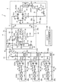
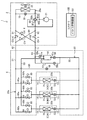
第1暖房主体運転は、全空調負荷のうち、冷房負荷がゼロから約20%程度と少ない第1負荷領域で行われる運転である。第1暖房主体運転の例として全暖房運転を図2に基づいて説明する。
<First heating main operation>
The first heating main operation is an operation performed in a first load region where the cooling load is as small as about 20% from zero among all the air conditioning loads. As an example of the first heating main operation, the all heating operation will be described with reference to FIG.
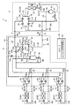
全暖房運転は、全ての室内ユニット(3A, 3B, 3C)で暖房を行うものである。全暖房運転の室外ユニット(2)では、三方弁(24)が第1状態に設定され、室外第2電動弁(36)、室外第4電動弁(38)が開放され、室外第1電動弁(35)、室外第3電動弁(37)、中間第4電動弁(59c)、及び電磁弁(29)が閉鎖される。気液分離ユニット(4)では、中間第3電動弁(59b)が開放され、中間第1電動弁(58)及び中間第2電動弁(59a)が閉鎖される。運転切換ユニット(5)では、全ての運転切換ユニット(5A, 5B, 5C)において、第2切換弁(64)が開放され、第1切換弁(63)が閉鎖される。室内ユニット(3)では、全ての室内ユニット(3A, 3B, 3C)において、室内膨張弁(72)が開放される。 In the all-heating operation, heating is performed in all indoor units (3A, 3B, 3C). In the all-heating outdoor unit (2), the three-way valve (24) is set to the first state, the outdoor second motor-operated valve (36) and the outdoor fourth motor-operated valve (38) are opened, and the outdoor first motor-operated valve (35), the outdoor third electric valve (37), the intermediate fourth electric valve (59c), and the electromagnetic valve (29) are closed. In the gas-liquid separation unit (4), the intermediate third electric valve (59b) is opened, and the intermediate first electric valve (58) and the intermediate second electric valve (59a) are closed. In the operation switching unit (5), the second switching valve (64) is opened and the first switching valve (63) is closed in all the operation switching units (5A, 5B, 5C). In the indoor unit (3), the indoor expansion valve (72) is opened in all the indoor units (3A, 3B, 3C).
圧縮機(21)を起動すると、吐出された高圧ガス冷媒は、切換回路(25)を通って室外部第2連絡配管(12)から気液分離ユニット(4)に流入する。高圧ガス冷媒は、気液分離器(41)を通って中間部第3連絡配管(17)から各運転切換ユニット(5)に流入し、さらに室内部第2連絡配管(14)を通って各室内ユニット(3)へ流入する。冷媒は室内熱交換器(71)で凝縮して室内空気を加熱した後、各室内ユニット(3)から流出し、室内部第1連絡配管(13)、各運転切換ユニット(5)、中間部第1連絡配管(15)を通って気液分離ユニット(4)へ流入する。液冷媒は、中間第3電動弁(59b)、冷媒流路切換回路(42)、及び室外部第1連絡配管(11)を通り、室外ユニット(2)へ戻る。室外ユニット(2)に流入した液冷媒は、切換回路(25)の室外第2電動弁(36)で膨張した後に室外熱交換器(22)で蒸発し、圧縮機(21)に吸入される。 When the compressor (21) is started, the discharged high-pressure gas refrigerant flows into the gas-liquid separation unit (4) from the outdoor second communication pipe (12) through the switching circuit (25). The high-pressure gas refrigerant flows into the operation switching unit (5) from the intermediate third communication pipe (17) through the gas-liquid separator (41), and further passes through the second indoor communication pipe (14). It flows into the indoor unit (3). The refrigerant condenses in the indoor heat exchanger (71) and heats indoor air, and then flows out from each indoor unit (3). The indoor first communication pipe (13), each operation switching unit (5), and the intermediate part It flows into the gas-liquid separation unit (4) through the first connection pipe (15). The liquid refrigerant passes through the intermediate third motor-operated valve (59b), the refrigerant flow path switching circuit (42), and the outdoor first communication pipe (11) and returns to the outdoor unit (2). The liquid refrigerant flowing into the outdoor unit (2) expands in the outdoor second motor-operated valve (36) of the switching circuit (25), evaporates in the outdoor heat exchanger (22), and is sucked into the compressor (21). .
冷媒が以上のようにして冷媒回路(20)を循環することにより、室内ユニット(3)のすべてで暖房が行われる。 As the refrigerant circulates in the refrigerant circuit (20) as described above, heating is performed in all the indoor units (3).
なお、上述の例では、中間第3電動弁(59b)が開放され、切り換え回路(25)の室外第2電動弁(36)で冷媒を膨脹させる例を説明したが、中間第3電動弁(59b)で冷媒を膨脹させ、室外第2電動弁(36)を開放する構成でもよく、両方の電動弁(59b,36)を用いれ冷媒を膨脹させてもよい。 In the above example, the intermediate third motor-operated valve (59b) is opened and the refrigerant is expanded by the outdoor second motor-operated valve (36) of the switching circuit (25). The configuration may be such that the refrigerant is expanded in 59b) and the outdoor second motor-operated valve (36) is opened, or both motor-operated valves (59b, 36) may be used to expand the refrigerant.
また、図2では第1暖房主体運転として全暖房運転を説明したが、第1暖房主体運転には、図3に示すように複数の室内ユニット(3)の一部で冷房を行う運転も含まれる。 In FIG. 2, the heating only operation has been described as the first heating main operation. However, the first heating main operation includes an operation in which cooling is performed by a part of the plurality of indoor units (3) as shown in FIG. 3. It is.
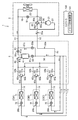
このとき、室外ユニット(2)では、三方弁(24)が第1位置に設定され、切り換え回路(25)が第1位置に設定され、電磁弁(29)が閉鎖される。また、室外第2電動弁(36)は開放される。気液分離ユニット(4)では、中間第3電動弁(59b)が所定開度に調整され、中間第1電動弁(58)と中間第2電動弁(59a)と中間第4電動弁(59c)が閉鎖される。暖房を行う第1運転切り換えユニット(5A)と第2運転切り換えユニット(5B)では、第2切り換え弁(64)が開放され、第1切り換え弁(63)が閉鎖され、冷房を行う第3運転切り換えユニット(5C)では、第1切り換え弁(63)が開放され、第2切り換え弁(64)が閉鎖される。 At this time, in the outdoor unit (2), the three-way valve (24) is set to the first position, the switching circuit (25) is set to the first position, and the electromagnetic valve (29) is closed. The outdoor second motor operated valve (36) is opened. In the gas-liquid separation unit (4), the intermediate third motor-operated valve (59b) is adjusted to a predetermined opening, and the intermediate first motor-operated valve (58), the intermediate second motor-operated valve (59a), and the intermediate fourth motor-operated valve (59c) ) Will be closed. In the first operation switching unit (5A) and the second operation switching unit (5B) that perform heating, the second switching valve (64) is opened, the first switching valve (63) is closed, and the third operation that performs cooling is performed. In the switching unit (5C), the first switching valve (63) is opened and the second switching valve (64) is closed.
圧縮機(21)を起動すると、吐出された高圧ガス冷媒は、切り換え回路(25)を通って室外部第2連絡配管(12)から気液分離ユニット(4)に流入する。高圧ガス冷媒は、気液分離器(41)を通って中間部第3連絡配管(17)から第1,第2運転切り換えユニット(5A,5B)に流入し、さらに室内部第2連絡配管(14)を通って第1,第2室内ユニット(3A,3B)へ流入する。冷媒は室内熱交換器(71)で凝縮して室内空気を加熱した後、第1,第2室内ユニット(3A,3B)から流出し、室内部第1連絡配管(13)、第1,第2運転切り換えユニット(5A,5B)を通り、中間部第1連絡配管(15)で気液分離ユニット(4)へ流入する冷媒と、第3運転切り換えユニット(5C)へ流入する冷媒に分流する。 When the compressor (21) is started, the discharged high-pressure gas refrigerant flows into the gas-liquid separation unit (4) from the outdoor second connection pipe (12) through the switching circuit (25). The high-pressure gas refrigerant flows into the first and second operation switching units (5A, 5B) from the intermediate third communication pipe (17) through the gas-liquid separator (41), and further to the indoor second communication pipe ( 14) flows into the first and second indoor units (3A, 3B). The refrigerant condenses in the indoor heat exchanger (71) and heats the indoor air, and then flows out of the first and second indoor units (3A, 3B), and the indoor first communication pipe (13), first, first The refrigerant passes through the 2 operation switching unit (5A, 5B) and is divided into the refrigerant flowing into the gas-liquid separation unit (4) and the refrigerant flowing into the third operation switching unit (5C) through the intermediate first connection pipe (15). .
第3運転切り換えユニット(5C)から、冷媒は室内部第1連絡配管(13)を通って第3室内ユニット(3C)へ流入して室内熱交換器(71)で蒸発し、室内部第2連絡配管(14)から中間部第2連絡配管(16)を通って気液分離ユニット(4)に戻る。 From the third operation switching unit (5C), the refrigerant flows into the third indoor unit (3C) through the indoor first communication pipe (13) and evaporates in the indoor heat exchanger (71). Return from the connection pipe (14) to the gas-liquid separation unit (4) through the intermediate second connection pipe (16).
中間部第1連絡配管(15)から気液分離ユニット(4)に流入した液冷媒は、中間第3電動弁(59b)で減圧され、低圧二相冷媒になって第2接続管(52)へ流入する。中間部第2連絡配管(16)から気液分離ユニット(4)に流入したガス冷媒は、第1接続管(51)、第1接続点(P21)、通路(43a)、及び第2接続点(P22)を通って、第2接続管(52)の低圧二相冷媒と合流する。合流した冷媒は低圧二相である。 The liquid refrigerant flowing into the gas-liquid separation unit (4) from the intermediate first communication pipe (15) is depressurized by the intermediate third motor operated valve (59b) and becomes a low-pressure two-phase refrigerant in the second connection pipe (52). Flow into. The gas refrigerant that has flowed into the gas-liquid separation unit (4) from the intermediate second connection pipe (16) includes the first connection pipe (51), the first connection point (P21), the passage (43a), and the second connection point. It passes through (P22) and merges with the low-pressure two-phase refrigerant of the second connection pipe (52). The merged refrigerant is low-pressure two-phase.
この低圧二相冷媒は、室外部第1連絡配管(11)を通って室外ユニット(2)へ戻り、切り換え回路(25)の室外第2電動弁(36)を通過した後に室外熱交換器(22)で蒸発し、圧縮機(21)に吸入される。 This low-pressure two-phase refrigerant returns to the outdoor unit (2) through the outdoor first communication pipe (11), passes through the outdoor second motor-operated valve (36) of the switching circuit (25), and then enters the outdoor heat exchanger ( It evaporates in 22) and is sucked into the compressor (21).
冷媒が以上のようにして冷媒回路(20)を循環することにより、室内ユニット(3)のほとんどで暖房が行われ、一部で冷房が行われる。 As the refrigerant circulates in the refrigerant circuit (20) as described above, heating is performed in most of the indoor units (3), and cooling is performed in part.
〈第2暖房主体運転〉
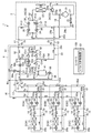
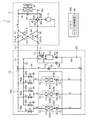
第2暖房主体運転は、全空調負荷のうち、冷房負荷が約20%から50%の第2負荷領域で行われる運転である。ここでは、図4に示すように、第1,第2室内ユニット(3A,3B)で暖房をし、第3室内ユニット(3C)で冷房を行う状態を例に説明する。
<Second heating main operation>
The second heating main operation is an operation performed in the second load region where the cooling load is about 20% to 50% of the total air conditioning load. Here, as shown in FIG. 4, an example will be described in which heating is performed by the first and second indoor units (3A, 3B) and cooling is performed by the third indoor unit (3C).
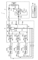
図4に示す第2暖房主体運転は、空気調和装置(1)の全体の空調負荷のうち、暖房負荷が冷房負荷よりも大きいときに行われる運転である。ここでは、第1,第2室内ユニット(3A,3B)で暖房をし、第3室内ユニット(3C)で冷房を行う状態を例に説明する。室外ユニット(2)では、三方弁(24)が第1状態に設定され、室外第1電動弁(35)、室外第3電動弁(37)、及び中間第4電動弁(59c)が開放され、室外第2電動弁(36)、室外第4電動弁(38)、及び電磁弁(29)が閉鎖される。気液分離ユニット(4)では、中間第2電動弁(59a)が開放され、中間第1電動弁(58)及び中間第3電動弁(59b)が閉鎖される。第1,第2運転切換ユニット(5A,5B)では、第2切換弁(64)が開放され、第1切換弁(63)が閉鎖される。第3運転切換ユニット(5C)では、第1切換弁(63)が開放され、第2切換弁(64)が閉鎖される。第1,第2室内ユニット(3A, 3B)では、室内膨張弁(72)が開放される。第3室内ユニット(3C)では、室内膨張弁(72)の開度が調節される。 The second heating main operation shown in FIG. 4 is an operation performed when the heating load is larger than the cooling load among the entire air conditioning load of the air conditioner (1). Here, an example will be described in which heating is performed by the first and second indoor units (3A, 3B) and cooling is performed by the third indoor unit (3C). In the outdoor unit (2), the three-way valve (24) is set to the first state, and the outdoor first motor-operated valve (35), the outdoor third motor-operated valve (37), and the intermediate fourth motor-operated valve (59c) are opened. The outdoor second motor-operated valve (36), the outdoor fourth motor-operated valve (38), and the electromagnetic valve (29) are closed. In the gas-liquid separation unit (4), the intermediate second electric valve (59a) is opened, and the intermediate first electric valve (58) and the intermediate third electric valve (59b) are closed. In the first and second operation switching units (5A, 5B), the second switching valve (64) is opened and the first switching valve (63) is closed. In the third operation switching unit (5C), the first switching valve (63) is opened and the second switching valve (64) is closed. In the first and second indoor units (3A, 3B), the indoor expansion valve (72) is opened. In the third indoor unit (3C), the opening degree of the indoor expansion valve (72) is adjusted.
圧縮機(21)を起動すると、吐出された高圧ガス冷媒は、切換回路(25)を通って室外部第1連絡配管(11)から気液分離ユニット(4)に流入する。高圧ガス冷媒は、冷媒流路切換回路(42)を通って気液分離器(41)に流入する。高圧ガス冷媒は気液分離器(41)のガス冷媒流出口(41b)から流出して中間部第3連絡配管(17)を通り、各運転切換ユニット(5)に流入する。 When the compressor (21) is started, the discharged high-pressure gas refrigerant flows into the gas-liquid separation unit (4) from the outdoor first communication pipe (11) through the switching circuit (25). The high-pressure gas refrigerant flows into the gas-liquid separator (41) through the refrigerant flow switching circuit (42). The high-pressure gas refrigerant flows out from the gas refrigerant outlet (41b) of the gas-liquid separator (41), passes through the intermediate third communication pipe (17), and flows into each operation switching unit (5).
上述したように、第1,第2運転切換ユニット(5A,5B)では、第2切換弁(64)が開放され、第1切換弁(63)が閉鎖されている。また、第3運転切換ユニット(5C)では、第1切換弁(63)が開放され、第2切換弁(64)が閉鎖されている。したがって、第1,第2運転切換ユニット(5A,5B)から室内部第2連絡配管(14)を通って、第1,第2室内ユニット(3A,3B)へ冷媒が流入する。この第1,第2室内ユニット(3A,3B)では冷媒が凝縮して放熱し、室内空気が加熱される。凝縮した液冷媒は第1,第2運転切換ユニット(5A,5B)に戻り、一部が第3運転切換ユニット(5C)へ向かい、他の一部が気液分離ユニット(4)へ向かう。 As described above, in the first and second operation switching units (5A, 5B), the second switching valve (64) is opened and the first switching valve (63) is closed. In the third operation switching unit (5C), the first switching valve (63) is opened and the second switching valve (64) is closed. Accordingly, the refrigerant flows from the first and second operation switching units (5A, 5B) through the indoor second communication pipe (14) to the first and second indoor units (3A, 3B). In the first and second indoor units (3A, 3B), the refrigerant condenses and dissipates heat, and the indoor air is heated. The condensed liquid refrigerant returns to the first and second operation switching units (5A, 5B), a part thereof goes to the third operation switching unit (5C), and the other part goes to the gas-liquid separation unit (4).
第3運転切換ユニット(5C)に流入した液冷媒は、さらに室内部第1連絡配管(13)を通って第3室内ユニット(3C)に流入し、室内膨張弁(72)で減圧されて低圧二相冷媒となる。この低圧二相冷媒は室内熱交換器(71)で蒸発してガス冷媒になり、第3室内ユニット(3C)から室内部第1連絡配管(13)を通って第3運転切換ユニット(5C)に流入する。第3運転切換ユニット(5C)に流入したガス冷媒は、第1分岐管(62a)から中間部第2連絡配管(16)を通って気液分離ユニット(4)に流入する。 The liquid refrigerant that has flowed into the third operation switching unit (5C) further flows into the third indoor unit (3C) through the indoor first communication pipe (13), and is reduced in pressure by the indoor expansion valve (72). It becomes a two-phase refrigerant. This low-pressure two-phase refrigerant evaporates into a gas refrigerant in the indoor heat exchanger (71), and passes from the third indoor unit (3C) through the indoor first communication pipe (13) to the third operation switching unit (5C). Flow into. The gas refrigerant that has flowed into the third operation switching unit (5C) flows from the first branch pipe (62a) into the gas-liquid separation unit (4) through the intermediate second communication pipe (16).
気液分離ユニット(4)では、第1,第2運転切換ユニット(5A,5B)から流入した液冷媒が中間第2電動弁(59a)で減圧されて低圧二相冷媒となり、第3運転切換ユニット(5C)から流入した低圧ガス冷媒と合流する。低圧二相冷媒と低圧ガス冷媒が混合された冷媒は低圧二相冷媒であり、この低圧二相冷媒は冷媒流路切換回路(42)から室外部第2連絡配管(12)を通って室外ユニット(2)に戻っていく。室外ユニット(2)に戻った低圧二相冷媒は、切換回路(25)を通って室外熱交換器(22)に流入し、室外空気と熱交換して蒸発する。室外熱交換器(22)で蒸発した低圧ガス冷媒は、三方弁(24)を通って圧縮機(21)に吸入される。 In the gas-liquid separation unit (4), the liquid refrigerant flowing in from the first and second operation switching units (5A, 5B) is depressurized by the intermediate second electric valve (59a) to become a low-pressure two-phase refrigerant, and the third operation switching. Combines with the low-pressure gas refrigerant flowing in from the unit (5C). The refrigerant in which the low-pressure two-phase refrigerant and the low-pressure gas refrigerant are mixed is a low-pressure two-phase refrigerant, and this low-pressure two-phase refrigerant passes through the second outdoor connection pipe (12) from the refrigerant flow switching circuit (42) to the outdoor unit. Return to (2). The low-pressure two-phase refrigerant that has returned to the outdoor unit (2) flows into the outdoor heat exchanger (22) through the switching circuit (25), evaporates by exchanging heat with the outdoor air. The low-pressure gas refrigerant evaporated in the outdoor heat exchanger (22) is sucked into the compressor (21) through the three-way valve (24).
冷媒が以上のようにして冷媒回路(20)を循環することにより、第1,第2室内ユニット(3A,3B)で暖房をし、第3室内ユニット(3C)で冷房をする冷凍サイクルが行われる。 As the refrigerant circulates in the refrigerant circuit (20) as described above, a refrigeration cycle is performed in which the first and second indoor units (3A, 3B) heat and the third indoor unit (3C) cools. Is called.
〈第1冷房主体運転〉
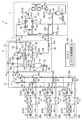
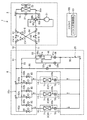
次に、第1冷房主体運転として、第1室内ユニット(3A)で暖房をし、第2,第3室内ユニット(3B,3C)で冷房をする状態を、図5に基づいて説明する。室外ユニット(2)では、三方弁(24)が第2状態に設定され、室外第1電動弁(35)、室外第2電動弁(36)、及び電磁弁(29)が開放され、室外第3電動弁(37)と室外第4電動弁(38)とが閉鎖される。気液分離ユニット(4)では、中間第1電動弁(58)が開放され、中間第2電動弁(59a)及び中間第3電動弁(59b)が閉鎖される。第1運転切換ユニット(5A)では、第2切換弁(64)が開放され、第1切換弁(63)が閉鎖される。第2,第3運転切換ユニット(5)では、第1切換弁(63)が開放され、第2切換弁(64)が閉鎖される。第1室内ユニット(3A)では、室内膨張弁(72)が開放される。第2,第3室内ユニット(3B, 3C)では、室内膨張弁(72)の開度が調節される。
<First cooling operation>
Next, as the first cooling main operation, a state in which heating is performed by the first indoor unit (3A) and cooling is performed by the second and third indoor units (3B, 3C) will be described with reference to FIG. In the outdoor unit (2), the three-way valve (24) is set to the second state, the outdoor first electric valve (35), the outdoor second electric valve (36), and the electromagnetic valve (29) are opened, The three motor-operated valves (37) and the outdoor fourth motor-operated valve (38) are closed. In the gas-liquid separation unit (4), the intermediate first electric valve (58) is opened, and the intermediate second electric valve (59a) and the intermediate third electric valve (59b) are closed. In the first operation switching unit (5A), the second switching valve (64) is opened and the first switching valve (63) is closed. In the second and third operation switching units (5), the first switching valve (63) is opened and the second switching valve (64) is closed. In the first indoor unit (3A), the indoor expansion valve (72) is opened. In the second and third indoor units (3B, 3C), the opening degree of the indoor expansion valve (72) is adjusted.
圧縮機(21)を起動すると、吐出された高圧ガス冷媒は、一部が三方弁(24)を通って室外熱交換器(22)へ流入し、該室外熱交換器(22)で凝縮して液冷媒となり、切換回路(25)に流入する。また、圧縮機(21)から吐出された高圧ガス冷媒の他の一部は、ガス冷媒のまま切換回路(25)に流入する。そして、液冷媒とガス冷媒が切換回路(25)で混合されて高圧二相冷媒になり、室外部第1連絡配管(11)を通って気液分離ユニット(4)に流入する。 When the compressor (21) is started, a part of the discharged high-pressure gas refrigerant flows into the outdoor heat exchanger (22) through the three-way valve (24) and is condensed in the outdoor heat exchanger (22). It becomes liquid refrigerant and flows into the switching circuit (25). The other part of the high-pressure gas refrigerant discharged from the compressor (21) flows into the switching circuit (25) as the gas refrigerant. Then, the liquid refrigerant and the gas refrigerant are mixed in the switching circuit (25) to become a high-pressure two-phase refrigerant, and flow into the gas-liquid separation unit (4) through the outdoor first communication pipe (11).
気液分離ユニット(4)に流入した高圧二相冷媒は、冷媒流路切換回路(42)を通って気液分離器(41)に流入し、液冷媒とガス冷媒に分離される。ガス冷媒は、中間部第3連絡配管(17)から第1運転切換ユニット(5A)へ流入し、さらに室内部第2連絡配管(14)を通って第1室内ユニット(3A)に流入する。第1室内ユニット(3A)では、室内熱交換器(71)において冷媒が凝縮して放熱し、室内空気が加熱される。第1室内ユニット(3A)の室内熱交換器(71)で凝縮した液冷媒は、気液分離器(41)から流出した液冷媒と合流し、第2,第3運転切換ユニット(5B,5C)へ向かう。 The high-pressure two-phase refrigerant that has flowed into the gas-liquid separation unit (4) flows into the gas-liquid separator (41) through the refrigerant flow switching circuit (42), and is separated into liquid refrigerant and gas refrigerant. The gas refrigerant flows from the intermediate third communication pipe (17) into the first operation switching unit (5A), and further flows through the indoor second communication pipe (14) into the first indoor unit (3A). In the first indoor unit (3A), the refrigerant is condensed and dissipated in the indoor heat exchanger (71), and the indoor air is heated. The liquid refrigerant condensed in the indoor heat exchanger (71) of the first indoor unit (3A) merges with the liquid refrigerant flowing out of the gas-liquid separator (41), and the second and third operation switching units (5B, 5C). Head to).
第2,第3運転切換ユニット(5B,5C)に流入した液冷媒は、室内部第1連絡配管(13)を通って第2,第3室内ユニット(3B,3C)へ流入し、室内膨張弁(72)で減圧された後に室内熱交換器(71)で蒸発する。このとき、室内空気が冷却される。室内熱交換器(71)を通過したガス冷媒は、室内部第2連絡配管(14)、第2,第3運転切換ユニット(5B,5C)、中間部第2連絡配管(16)を通って気液分離ユニット(4)に流入する。この冷媒は、気液分離ユニット(4)の冷媒流路切換回路(42)と室外部第2連絡配管(12)を通って室外ユニット(2)へ戻り、電磁弁(29)を通って圧縮機(21)に吸入される。 The liquid refrigerant that has flowed into the second and third operation switching units (5B, 5C) flows into the second and third indoor units (3B, 3C) through the indoor first communication pipe (13) and is expanded indoors. After being depressurized by the valve (72), it is evaporated by the indoor heat exchanger (71). At this time, the room air is cooled. The gas refrigerant that has passed through the indoor heat exchanger (71) passes through the indoor second communication pipe (14), the second and third operation switching units (5B, 5C), and the intermediate second communication pipe (16). It flows into the gas-liquid separation unit (4). This refrigerant returns to the outdoor unit (2) through the refrigerant flow switching circuit (42) of the gas-liquid separation unit (4) and the outdoor second connection pipe (12), and is compressed through the solenoid valve (29). Inhaled into the machine (21).
冷媒が以上のようにして冷媒回路(20)を循環することにより、第1室内ユニット(3A)で暖房をし、第2,第3室内ユニット(3B,3C)で冷房をする冷凍サイクルが行われる。 As the refrigerant circulates in the refrigerant circuit (20) as described above, a refrigeration cycle is performed in which the first indoor unit (3A) heats and the second and third indoor units (3B, 3C) cool. Is called.
〈第2冷房主体運転〉
次に、全冷房運転である第2冷房主体運転を図6に基づいて説明する。全冷房運転の室外ユニット(2)では、三方弁(24)が第2状態に設定され、室外第2電動弁(36)及び電磁弁(29)が開放され、室外第1電動弁(35)、室外第3電動弁(37)、及び室外第4電動弁(38)が閉鎖される。気液分離ユニット(4)では、中間第3電動弁(59b)が開放され、中間第1電動弁(58)、中間第2電動弁(59a)、及び中間第4電動弁(59c)が閉鎖される。運転切換ユニット(5)では、全ての運転切換ユニット(5)において、第1切換弁(63)が開放され、第2切換弁(64)が閉鎖される。室内ユニット(3)では、全ての室内ユニット(3A, 3B, 3C)において、室内膨張弁(72)の開度が調節される。
<Second cooling-dominated operation>
Next, the second cooling main operation that is a cooling only operation will be described with reference to FIG. In the outdoor unit (2) for the cooling only operation, the three-way valve (24) is set to the second state, the outdoor second electric valve (36) and the electromagnetic valve (29) are opened, and the outdoor first electric valve (35) The outdoor third electric valve (37) and the outdoor fourth electric valve (38) are closed. In the gas-liquid separation unit (4), the intermediate third motor-operated valve (59b) is opened, and the intermediate first motor-operated valve (58), the intermediate second motor-operated valve (59a), and the intermediate fourth motor-operated valve (59c) are closed. Is done. In the operation switching unit (5), the first switching valve (63) is opened and the second switching valve (64) is closed in all the operation switching units (5). In the indoor unit (3), the opening degree of the indoor expansion valve (72) is adjusted in all the indoor units (3A, 3B, 3C).
圧縮機(21)を起動すると、吐出された高圧ガス冷媒は、三方弁(24)を通って室外熱交換器(22)へ流入し、該室外熱交換器(22)で凝縮して液冷媒となる。この高圧液冷媒は切換回路(25)を通り、さらに室外部第1連絡配管(11)を通って気液分離ユニット(4)に流入する。 When the compressor (21) is started, the discharged high-pressure gas refrigerant flows into the outdoor heat exchanger (22) through the three-way valve (24) and is condensed by the outdoor heat exchanger (22). It becomes. The high-pressure liquid refrigerant passes through the switching circuit (25), and further flows into the gas-liquid separation unit (4) through the outdoor first communication pipe (11).
気液分離ユニット(4)に流入した高圧液冷媒は、冷媒流路切換回路(42)と気液分離器(41)を通過せず、中間第3電動弁(59b)を通って中間部第1連絡配管(15)から流出し、各運転切換ユニット(5)に流入する。 The high-pressure liquid refrigerant flowing into the gas-liquid separation unit (4) does not pass through the refrigerant flow switching circuit (42) and the gas-liquid separator (41), passes through the intermediate third motor-operated valve (59b), It flows out from one connection pipe (15) and flows into each operation switching unit (5).
高圧液冷媒は、各運転切換ユニット(5)を通過し、室内部第1連絡配管(13)から各室内ユニット(3)へ流入する。高圧液冷媒は各室内ユニット(3)の室内膨張弁(72)で減圧され、室内熱交換器(71)で蒸発する。室内熱交換器(71)で蒸発したガス冷媒は、室内部第2連絡配管(14)と運転切換ユニット(5)の第1分岐管(62a)と中間部第2連絡配管(16)を通って気液分離ユニット(4)に流入する。この低圧ガス冷媒は、気液分離ユニット(4)の冷媒流路切換回路(42)と室外部第2連絡配管(12)を通って室外ユニット(2)に戻る。室外ユニット(2)に戻った低圧ガス冷媒は電磁弁(29)を通って圧縮機(21)に吸入される。 The high-pressure liquid refrigerant passes through each operation switching unit (5) and flows into each indoor unit (3) from the indoor first communication pipe (13). The high-pressure liquid refrigerant is depressurized by the indoor expansion valve (72) of each indoor unit (3) and is evaporated by the indoor heat exchanger (71). The gas refrigerant evaporated in the indoor heat exchanger (71) passes through the indoor second communication pipe (14), the first branch pipe (62a) of the operation switching unit (5), and the intermediate second communication pipe (16). Flow into the gas-liquid separation unit (4). This low-pressure gas refrigerant returns to the outdoor unit (2) through the refrigerant flow switching circuit (42) of the gas-liquid separation unit (4) and the outdoor second communication pipe (12). The low-pressure gas refrigerant that has returned to the outdoor unit (2) passes through the solenoid valve (29) and is sucked into the compressor (21).
冷媒が以上のようにして冷媒回路(20)を循環することにより、室内ユニット(3)のすべてで冷房をする冷凍サイクルが行われる。 As the refrigerant circulates through the refrigerant circuit (20) as described above, a refrigeration cycle for cooling the entire indoor unit (3) is performed.
〈バイパス動作〉
上述した第1冷房主体運転では、気液分離器(41)へ供給される気液二相冷媒の乾き度を調節するために、バイパス動作が行われる。具体的に、第1冷房主体運転では、全体の冷房負荷に対する全体の暖房負荷の比率(暖房比率)が求められる。この暖房比率は、冷房運転や暖房運転が行われる室内ユニット(3)の台数、各室内ユニット(3A, 3B, 3C)の冷房負荷や暖房負荷等に基づいてコントローラ(100)で算出される。第1冷房主体運転では、バイパス弁制御部(101)が、このようにして求められた暖房比率に応じて、室外第1電動弁(35)の開度を適宜調節する。
<Bypass operation>
In the first cooling main operation described above, a bypass operation is performed to adjust the dryness of the gas-liquid two-phase refrigerant supplied to the gas-liquid separator (41). Specifically, in the first cooling main operation, the ratio of the entire heating load to the entire cooling load (heating ratio) is obtained. The heating ratio is calculated by the controller (100) based on the number of indoor units (3) in which cooling operation or heating operation is performed, the cooling load or heating load of each indoor unit (3A, 3B, 3C), and the like. In the first cooling main operation, the bypass valve control unit (101) appropriately adjusts the opening degree of the outdoor first electric valve (35) in accordance with the heating ratio thus obtained.
より詳細に、第1冷房主体運転では、圧縮機(21)で圧縮された高圧ガス冷媒の一部が、室外熱交換器(22)で凝縮する。冷媒回路(20)では、室外熱交換器(22)を流出する冷媒が液冷媒となるように、ファンの風量や冷媒の流量が調節される。つまり、冷媒回路(20)は、第1冷房主体運転において、室外熱交換器(22)を流出する冷媒が液状態となるように構成される。 More specifically, in the first cooling main operation, a part of the high-pressure gas refrigerant compressed by the compressor (21) is condensed by the outdoor heat exchanger (22). In the refrigerant circuit (20), the air volume of the fan and the flow rate of the refrigerant are adjusted so that the refrigerant flowing out of the outdoor heat exchanger (22) becomes a liquid refrigerant. That is, the refrigerant circuit (20) is configured such that the refrigerant flowing out of the outdoor heat exchanger (22) is in a liquid state in the first cooling main operation.
一方、圧縮機(21)で圧縮された高圧ガス冷媒の残りは、バイパス管(18)及び第1通路(31)を流出し、室外熱交換器(22)で凝縮した液冷媒と混合する。これにより、この冷媒は、所望の乾き度を有する高圧の気液二相状態となる。混合後の冷媒は、室外部第1連絡配管(11)及び冷媒流路切換回路(42)を順に流れ、気液分離器(41)に流入する。気液分離器(41)に供給された冷媒は、所望の乾き度の気液二相状態となっている。このため、気液分離器(41)では、分離後のガス冷帯と液冷媒の比率を最適に調節できる。この結果、暖房側の室内ユニット(3A)へ最適な流量のガス冷媒を供給できると同時に、冷房側の室内ユニット(3B, 3C)へ最適な流量の液冷媒を供給できる。 On the other hand, the remainder of the high-pressure gas refrigerant compressed by the compressor (21) flows out of the bypass pipe (18) and the first passage (31) and is mixed with the liquid refrigerant condensed in the outdoor heat exchanger (22). Thereby, this refrigerant | coolant will be in the high-pressure gas-liquid two-phase state which has desired dryness. The mixed refrigerant flows through the outdoor first communication pipe (11) and the refrigerant flow switching circuit (42) in order, and then flows into the gas-liquid separator (41). The refrigerant supplied to the gas-liquid separator (41) is in a gas-liquid two-phase state with a desired dryness. For this reason, in the gas-liquid separator (41), the ratio between the gas cold zone after separation and the liquid refrigerant can be optimally adjusted. As a result, an optimal flow rate of gas refrigerant can be supplied to the indoor unit (3A) on the heating side, and at the same time, liquid refrigerant with an optimal flow rate can be supplied to the indoor units (3B, 3C) on the cooling side.
−実施形態1の効果−
上記実施形態1によれば、上述した第1冷房主体運転において、室外熱交換器(22)で放熱した冷媒の流量と、バイパス管(18)を流出した冷媒の流量との比率を調節するため、気液分離器(41)へ供給される冷媒の乾き度を調節できる。この結果、気液分離器(41)で分離されるガス冷媒と液冷媒の割合を容易に変更でき、暖房側の室内熱交換器(71)と冷房側の室内熱交換器(71)とに最適な流量の冷媒を供給できる。ここで、上記実施形態1では、室外熱交換器を複数のパスに分割するような構造ではなく、室外熱交換器(22)の構造も複雑とならない。この結果、空気調和装置(1)の簡素化、低コスト化を図ることができる。バイパス回路(18,31)と調節機構(35,81,101)とが設けられるだけであり、室外熱交換器(22)の構造が複雑とならない。また、実施形態1では、バイパス管(18)の冷媒の流量を制御することで、気液分離器(41)へ供給される冷媒の乾き度を細かく調節できる。
-Effect of Embodiment 1-
According to the first embodiment, in the first cooling main operation described above, the ratio between the flow rate of the refrigerant radiated by the outdoor heat exchanger (22) and the flow rate of the refrigerant flowing out of the bypass pipe (18) is adjusted. The dryness of the refrigerant supplied to the gas-liquid separator (41) can be adjusted. As a result, the ratio of the gas refrigerant to the liquid refrigerant separated by the gas-liquid separator (41) can be easily changed, and the heating-side indoor heat exchanger (71) and the cooling-side indoor heat exchanger (71) can be changed. An optimal flow rate of refrigerant can be supplied. Here, in the said
また、上記実施形態1では、第1冷房主体運転時の暖房比率に応じて、室外第1電動弁(35)の開度を調節している。このため、第1冷房主体運転では、暖房比率に応じた最適な流量のガス冷媒を暖房側の室内ユニット(3A)へ供給でき、且つ最適な流量の液冷媒を冷房側の室内ユニット(3B. 3C)へ供給できる。
Moreover, in the said
〈実施形態1の変形例〉
図7に示す実施形態1の変形例は、実施形態1における気液分離ユニット(4)と運転切換ユニット(5)を一体化して、一つの冷暖切換えユニット(6)(一体式の気液分離器ユニット)として構成した例である。冷媒回路(20)の構成は実施形態1と同じである。
<Modification of
In the modification of the first embodiment shown in FIG. 7, the gas-liquid separation unit (4) and the operation switching unit (5) in the first embodiment are integrated into one cooling / heating switching unit (6) (integrated gas-liquid separation). It is an example comprised as a unit. The configuration of the refrigerant circuit (20) is the same as that of the first embodiment.
この変形例では、冷暖切換ユニット(6)が、第1室外連絡配管ポート(6a)、第2室外連絡配管ポート(6b)、第1室内連絡配管ポート(6c)及び第2室内連絡配管ポート(6d)を有している。また、変形例では、中間部第1連絡配管(15)、中間部第2連絡配管(16)及び中間部第3連絡配管(17)がユニット内の配管で置き換えられている。 In this modification, the cooling / heating switching unit (6) includes a first outdoor communication piping port (6a), a second outdoor communication piping port (6b), a first indoor communication piping port (6c), and a second indoor communication piping port ( 6d). Moreover, in the modification, the intermediate part first connection pipe (15), the intermediate part second connection pipe (16), and the intermediate part third connection pipe (17) are replaced with pipes in the unit.
具体的には、この冷暖切換ユニット(6)において、冷媒回路(20)上で実施形態1の中間部第1連絡配管(15)に相当する部分の配管は、第6接続管(56)を延長して第1連通管(61)に接続した配管により構成されている。また、冷媒回路(20)上で実施形態1の中間部第2連絡配管(16)に相当する部分の配管は、第1接続管(51)を延長して第2連通管(62)の第1分岐管(62a)に接続した配管により構成されている。冷媒回路(20)上で実施形態1の中間部第3連絡配管(17)に相当する部分の配管は、第5接続管(55)を延長して第2連通管(62)の第2分岐管(62b)に接続した配管により構成されている。
Specifically, in this cooling / heating switching unit (6), the portion of the pipe corresponding to the intermediate first connecting pipe (15) of
この変形例のその他の構成は実施形態1と同じであるため、具体的な説明は省略する。また、運転動作も実施形態1と同じである。 Since the other configuration of this modification is the same as that of the first embodiment, a detailed description thereof will be omitted. The driving operation is also the same as that of the first embodiment.
《参考例1》
図8に示す参考例1は、実施形態1と構成が異なる冷暖フリー型の空気調和装置(1)である。空気調和装置(1)は、室外回路(20a)を有する室外ユニット(2)と、中継回路(20e)を有する冷暖切換ユニット(6)(気液分離ユニット)と、室内回路(20b)をそれぞれ有する複数(図8では3つ)の室内ユニット(3)とを備えている。
<< Reference Example 1 >>
Reference example 1 shown in FIG. 8 is a cooling / heating free type air conditioner (1) having a configuration different from that of the first embodiment. The air conditioner (1) includes an outdoor unit (2) having an outdoor circuit (20a), a cooling / heating switching unit (6) (gas-liquid separation unit) having a relay circuit (20e), and an indoor circuit (20b). And a plurality (three in FIG. 8) of indoor units (3).
室外回路(20a)には、圧縮機(21)と室外熱交換器(22)と四方切換弁(80)とが接続されている。四方切換弁(80)は、第1から第4までのポート(80a,80b,80c,80d)を有している。四方切換弁(80)では、第1ポート(80a)が圧縮機(21)の吐出側配管(26)に接続し、第2ポート(80b)が圧縮機(21)の吸入側配管(27)に接続し、第3ポート(80c)が室外部第2連絡配管(12)に接続し、第4ポート(80d)が室外熱交換器(22)のガス側端部に接続している。四方切換弁(80)は、第1ポート(80a)と第3ポート(80c)とが連通し、第2ポート(80b)と第4ポート(80d)とが連通する第1状態(図8の実線で示す状態)と、第1ポート(80a)と第4ポート(80d)とが連通し、第2ポート(80b)と第3ポート(80c)とが連通する第2状態(図8の破線で示す状態)とに切換可能に構成される。 A compressor (21), an outdoor heat exchanger (22), and a four-way selector valve (80) are connected to the outdoor circuit (20a). The four-way selector valve (80) has first to fourth ports (80a, 80b, 80c, 80d). In the four-way selector valve (80), the first port (80a) is connected to the discharge side piping (26) of the compressor (21), and the second port (80b) is connected to the suction side piping (27) of the compressor (21). The third port (80c) is connected to the outdoor second connection pipe (12), and the fourth port (80d) is connected to the gas side end of the outdoor heat exchanger (22). The four-way switching valve (80) is in a first state (FIG. 8) in which the first port (80a) and the third port (80c) communicate with each other, and the second port (80b) and the fourth port (80d) communicate with each other. The state shown by the solid line), the first port (80a) and the fourth port (80d) communicate with each other, and the second port (80b) and the third port (80c) communicate with each other (dashed line in FIG. 8). The state can be switched to the state shown in FIG.
中継回路(20e)には、気液分離器(41)と中間第1電動弁(58)と中間第3電動弁(59b)と中間第4電動弁(59c)と三方切換弁(83)(切換機構)とが接続されている。気液分離器(41)の冷媒流入口(41a)は、第3接続管(53)を介して室外部第1連絡配管(11)と接続している。気液分離器(41)のガス冷媒流出口(41b)は、第5接続管(55)と接続している。気液分離器(41)の液冷媒流出口(41c)は、第6接続管(56)を介して各室内部第1連絡配管(13)と接続している。 The relay circuit (20e) includes a gas-liquid separator (41), an intermediate first electric valve (58), an intermediate third electric valve (59b), an intermediate fourth electric valve (59c), and a three-way switching valve (83) ( Switching mechanism). The refrigerant inlet (41a) of the gas-liquid separator (41) is connected to the outdoor first communication pipe (11) via the third connection pipe (53). The gas refrigerant outlet (41b) of the gas-liquid separator (41) is connected to the fifth connecting pipe (55). The liquid refrigerant outlet (41c) of the gas-liquid separator (41) is connected to each indoor first communication pipe (13) via a sixth connection pipe (56).
中間第1電動弁(58)は、第6接続管(56)に接続されている。中間第3電動弁(59b)は、分岐管(57c)に接続されている。分岐管(57c)は、流入端が第3接続管(53)に接続し、流出端が第6接続管(56)における中間第1電動弁(58)の下流側に接続している。中間第4電動弁(59c)は、第3接続管(53)に接続されている。 The intermediate first motor operated valve (58) is connected to the sixth connecting pipe (56). The intermediate third electric valve (59b) is connected to the branch pipe (57c). The branch pipe (57c) has an inflow end connected to the third connection pipe (53) and an outflow end connected to the downstream side of the intermediate first electric valve (58) in the sixth connection pipe (56). The intermediate fourth electric valve (59c) is connected to the third connection pipe (53).
三方切換弁(83)は、第1から第3までのポート(83a,83b,83c)を有している。三方切換弁(83)の第1ポート(83a)は、第1分岐管(62a)、第1接続管(51)を介して室外部第2連絡配管(12)と接続している。三方切換弁(83)の第2ポート(83b)は、第2分岐管(62b)を介して第5接続管(55)と接続している。三方切換弁(83)の第3ポート(83c)は、室内部第2連絡配管(14)を介して室内回路(20b)と接続している。三方切換弁(83)は、第2ポート(83b)と第3ポート(83c)とが連通し、第1ポート(83a)が閉塞する第1状態(図8の実線で示す状態)と、第1ポート(83a)と第3ポート(83c)とが連通し、第2ポート(83b)が閉塞する第2状態(図8の破線で示す状態)とに切換可能に構成される。 The three-way switching valve (83) has first to third ports (83a, 83b, 83c). The first port (83a) of the three-way switching valve (83) is connected to the outdoor second communication pipe (12) via the first branch pipe (62a) and the first connection pipe (51). The second port (83b) of the three-way switching valve (83) is connected to the fifth connection pipe (55) via the second branch pipe (62b). The third port (83c) of the three-way switching valve (83) is connected to the indoor circuit (20b) via the indoor second communication pipe (14). The three-way switching valve (83) has a first state (state indicated by a solid line in FIG. 8) in which the second port (83b) and the third port (83c) communicate with each other and the first port (83a) is closed, The first port (83a) and the third port (83c) communicate with each other and can be switched to a second state (state indicated by a broken line in FIG. 8) in which the second port (83b) is closed.
また、参考例1の室外回路(20a)には、バイパス管(18)とバイパス弁(81)とが接続されている。バイパス管(18)の流入端は、圧縮機(21)の吐出側配管(26)に接続し、バイパス管(18)の流出端は、室外熱交換器(22)の液側端部と室外部第1連絡配管(11)との間に接続している。バイパス弁(81)は、バイパス管(18)に接続されている。バイパス弁(81)は、開度が調節自在な電動弁で構成される。 Further, a bypass pipe (18) and a bypass valve (81) are connected to the outdoor circuit (20a) of Reference Example 1 . The inflow end of the bypass pipe (18) is connected to the discharge side pipe (26) of the compressor (21), and the outflow end of the bypass pipe (18) is connected to the liquid side end of the outdoor heat exchanger (22) and the chamber. It is connected between the external first connection pipe (11). The bypass valve (81) is connected to the bypass pipe (18). The bypass valve (81) is an electric valve whose opening degree is adjustable.
参考例1のその他の構成は実施形態1と同じであるため、具体的な説明は省略する。 Since the other configuration of the reference example 1 is the same as that of the first embodiment, a specific description is omitted.
−運転動作−
参考例1の空気調和装置(1)の運転動作について説明する。空気調和装置(1)では、第1暖房主体運転と、第2暖房主体運転と、第1冷房主体運転と、第2冷房主体運転とが切り換えて行われる。
-Driving action-
The operation of the air conditioner (1) of Reference Example 1 will be described. In the air conditioner (1), the first heating main operation, the second heating main operation, the first cooling main operation, and the second cooling main operation are performed by switching.
〈第1暖房主体運転〉
図9に示す第1暖房主体運転(ここでは、全暖房運転)の室外ユニット(2)では、四方切換弁(80)が第1状態に設定され、バイパス弁(81)が全閉状態となる。また、冷暖切換ユニット(6)では、中間第1電動弁(58)及び中間第4電動弁(59c)が閉鎖され、中間第3電動弁(59b)の開度が調節され、全ての三方切換弁(83)が第2状態に設定される。各室内ユニット(3A, 3B, 3C)では、室内膨張弁(72)が開放される。
<First heating main operation>
In the outdoor unit (2) of the first heating main operation (here, the full heating operation) shown in FIG. 9, the four-way switching valve (80) is set to the first state, and the bypass valve (81) is fully closed. . In the cooling / heating switching unit (6), the intermediate first motor-operated valve (58) and the intermediate fourth motor-operated valve (59c) are closed, the opening degree of the intermediate third motor-operated valve (59b) is adjusted, and all three-way switching is performed. The valve (83) is set to the second state. In each indoor unit (3A, 3B, 3C), the indoor expansion valve (72) is opened.
圧縮機(21)を起動すると、吐出された高圧ガス冷媒は、室外部第2連絡配管(12)を通って各室内ユニット(3)へ流入する。冷媒は室内熱交換器(71)で凝縮して室内空気を加熱した後、各室内ユニット(3)から流出し、室内部第1連絡配管(13)、第6接続管(56)、分岐管(57c)を順に流れ、中間第3電動弁(59b)で減圧された後、室外ユニット(2)へ戻る。室外ユニット(2)に流入した液冷媒は、室外熱交換器(22)で蒸発し、圧縮機(21)に吸入される。 When the compressor (21) is started, the discharged high-pressure gas refrigerant flows into each indoor unit (3) through the outdoor second communication pipe (12). The refrigerant condenses in the indoor heat exchanger (71) and heats indoor air, then flows out from each indoor unit (3), and the indoor first communication pipe (13), sixth connection pipe (56), branch pipe (57c) flows in order, and after the pressure is reduced by the intermediate third motor operated valve (59b), the flow returns to the outdoor unit (2). The liquid refrigerant flowing into the outdoor unit (2) evaporates in the outdoor heat exchanger (22) and is sucked into the compressor (21).
〈第2暖房主体運転〉
図10に示すように、ここでは、第1,第2室内ユニット(3A,3B)で暖房をし、第3室内ユニット(3C)で冷房を行う第2暖房主体運転について説明する。室外ユニット(2)では、四方切換弁(80)が第1状態に設定され、バイパス弁(81)が全閉状態となる。また、冷暖切換ユニット(6)では、中間第1電動弁(58)が閉鎖され、中間第3電動弁(59b)の開度が調節され、中間第4電動弁(59c)が開放される。また、第1,第2室内ユニット(3A, 3B)に対応する三方切換弁(83)が第2状態に設定され、第3室内ユニット(3C)に対応する三方切換弁(83)が第1状態に設定される。第1,第2室内ユニット(3A, 3B)の室内膨張弁(72)が開放され、第3室内ユニット(3C)の室内膨張弁(72)の開度が調節される。
<Second heating main operation>
As shown in FIG. 10, here, the second heating main operation in which heating is performed by the first and second indoor units (3A, 3B) and cooling is performed by the third indoor unit (3C) will be described. In the outdoor unit (2), the four-way switching valve (80) is set to the first state, and the bypass valve (81) is fully closed. In the cooling / heating switching unit (6), the intermediate first electric valve (58) is closed, the opening degree of the intermediate third electric valve (59b) is adjusted, and the intermediate fourth electric valve (59c) is opened. Further, the three-way switching valve (83) corresponding to the first and second indoor units (3A, 3B) is set to the second state, and the three-way switching valve (83) corresponding to the third indoor unit (3C) is set to the first state. Set to state. The indoor expansion valve (72) of the first and second indoor units (3A, 3B) is opened, and the opening degree of the indoor expansion valve (72) of the third indoor unit (3C) is adjusted.
圧縮機(21)を起動すると、吐出された高圧ガス冷媒は、室外部第2連絡配管(12)を通って第1,第2室内ユニット(3A, 3B)へ流入し、室内熱交換器(71)で凝縮して室内空気を加熱する。第1,第2室内ユニット(3A, 3B)で凝縮した冷媒は、第6接続管(56)に流入し、一部が分岐管(57c)を流れる一方、残りは第3室内ユニット(3C)へ送られる。 When the compressor (21) is started, the discharged high-pressure gas refrigerant flows into the first and second indoor units (3A, 3B) through the outdoor second communication pipe (12), and the indoor heat exchanger ( 71) condenses and heats indoor air. The refrigerant condensed in the first and second indoor units (3A, 3B) flows into the sixth connecting pipe (56) and partly flows through the branch pipe (57c), while the rest flows through the third indoor unit (3C). Sent to.
分岐管(57c)を流れる冷媒は、中間第3電動弁(59b)で減圧された後、第3接続管(53)へ流出する。第3室内ユニット(3C)へ送られた冷媒は、室内膨張弁(72)で減圧された後、室内熱交換器(71)で室内空気から吸熱して蒸発する。第3室内ユニット(3C)で蒸発したガス冷媒は、第5接続管(55)、気液分離器(41)を順に通過し、第3接続管(53)へ送られる。第3接続管(53)では、ガス冷媒と液冷媒とが混合し、気液二相状態となる。この冷媒は、室外ユニット(2)へ送られ、室外熱交換器(22)で蒸発し、圧縮機(21)に吸入される。 The refrigerant flowing through the branch pipe (57c) is depressurized by the intermediate third electric valve (59b) and then flows out to the third connection pipe (53). The refrigerant sent to the third indoor unit (3C) is depressurized by the indoor expansion valve (72), and then absorbs heat from the indoor air by the indoor heat exchanger (71) and evaporates. The gas refrigerant evaporated in the third indoor unit (3C) sequentially passes through the fifth connecting pipe (55) and the gas-liquid separator (41) and is sent to the third connecting pipe (53). In the third connection pipe (53), the gas refrigerant and the liquid refrigerant are mixed to be in a gas-liquid two-phase state. This refrigerant is sent to the outdoor unit (2), is evaporated in the outdoor heat exchanger (22), and is sucked into the compressor (21).
〈第1冷房主体運転〉
図11に示すように、ここでは、第1室内ユニット(3A)で暖房をし、第2,第3室内ユニット(3B,3C)で冷房を行う第1冷房主体運転について説明する。室外ユニット(2)では、四方切換弁(80)が第2状態に設定され、バイパス弁(81)の開度が調節される。また、冷暖切換ユニット(6)では、中間第1電動弁(58)の開度が調節され、中間第4電動弁(59c)が開放され、中間第3電動弁(59b)が閉鎖される。また、第1室内ユニット(3A)に対応する三方切換弁(83)が第1状態に設定され、第2,第3室内ユニット(3B, 3C)に対応する三方切換弁(83)が第2状態に設定される。各室内ユニット(3A, 3B, 3C)では、第1室内ユニット(3A)の室内膨張弁(72)が開放され、第2,第3室内ユニット(3B, 3C)の開度が調節される。
<First cooling operation>
As shown in FIG. 11, here, the first cooling main operation in which heating is performed by the first indoor unit (3A) and cooling is performed by the second and third indoor units (3B, 3C) will be described. In the outdoor unit (2), the four-way switching valve (80) is set to the second state, and the opening degree of the bypass valve (81) is adjusted. In the cooling / heating switching unit (6), the opening degree of the intermediate first electric valve (58) is adjusted, the intermediate fourth electric valve (59c) is opened, and the intermediate third electric valve (59b) is closed. Further, the three-way switching valve (83) corresponding to the first indoor unit (3A) is set to the first state, and the three-way switching valve (83) corresponding to the second and third indoor units (3B, 3C) is set to the second state. Set to state. In each indoor unit (3A, 3B, 3C), the indoor expansion valve (72) of the first indoor unit (3A) is opened, and the opening degree of the second and third indoor units (3B, 3C) is adjusted.
圧縮機(21)を起動すると、吐出された高圧ガスは、一部が室外熱交換器(22)で凝縮して液冷媒となり、残りがバイパス管(18)を流れる。室外熱交換器(22)の流出側では、高圧の液冷媒とガス冷媒とが混合し、所定の乾き度の気液二相状態となる。この際、バイパス弁(81)の開度は、実施形態1と同様、空気調和装置(1)の暖房比率に応じて適宜調節される。乾き度が調節された冷媒は、室外部第1連絡配管(11)を通じて気液分離器(41)に流入する。 When the compressor (21) is started, a part of the discharged high-pressure gas is condensed in the outdoor heat exchanger (22) to become a liquid refrigerant, and the rest flows through the bypass pipe (18). On the outflow side of the outdoor heat exchanger (22), the high-pressure liquid refrigerant and the gas refrigerant are mixed to form a gas-liquid two-phase state with a predetermined dryness. At this time, the opening degree of the bypass valve (81) is appropriately adjusted according to the heating ratio of the air conditioner (1) as in the first embodiment. The refrigerant whose dryness is adjusted flows into the gas-liquid separator (41) through the outdoor first communication pipe (11).
気液分離器(41)では、気液二相状態の冷媒がガス冷媒と液冷媒とに分離される。ガス冷媒は、第5接続管(55)を経由して、第1室内ユニット(3A)へ送られる。第1室内ユニット(3A)では、冷媒が室内空気を加熱して凝縮する。第1室内ユニット(3A)の室内膨張弁(72)で減圧された冷媒は、第6接続管(56)へ送られる。気液分離器(41)で分離した液冷媒は、第6接続管(56)を経由して、第2室内ユニット(3B)と第3室内ユニット(3C)とへ送られる。第2,第3室内ユニット(3B, 3C)では、冷媒が室内膨張弁(72)で減圧された後、室内熱交換器(71)で室内空気から吸熱して蒸発する。蒸発した冷媒は、第6接続管(56)へ流出し、第1室内ユニット(3A)を流出した液冷媒と混合された後、室外ユニット(2)へ送られ、圧縮機(21)に吸入される。 In the gas-liquid separator (41), the gas-liquid two-phase refrigerant is separated into a gas refrigerant and a liquid refrigerant. The gas refrigerant is sent to the first indoor unit (3A) via the fifth connection pipe (55). In the first indoor unit (3A), the refrigerant heats the indoor air to condense. The refrigerant decompressed by the indoor expansion valve (72) of the first indoor unit (3A) is sent to the sixth connecting pipe (56). The liquid refrigerant separated by the gas-liquid separator (41) is sent to the second indoor unit (3B) and the third indoor unit (3C) via the sixth connection pipe (56). In the second and third indoor units (3B, 3C), after the refrigerant is depressurized by the indoor expansion valve (72), the refrigerant absorbs heat from the indoor air in the indoor heat exchanger (71) and evaporates. The evaporated refrigerant flows out to the sixth connecting pipe (56) and is mixed with the liquid refrigerant flowing out from the first indoor unit (3A), then sent to the outdoor unit (2) and sucked into the compressor (21). Is done.
〈第2冷房主体運転〉
図12に示す第2冷房主体運転(ここでは、全冷房運転)の室外ユニット(2)では、四方切換弁(80)が第2状態に設定され、バイパス弁(81)が全閉状態となる。また、冷暖切換ユニット(6)では、中間第1電動弁(58)及び中間第4電動弁(59c)が閉鎖され、中間第3電動弁(59b)が開放され、全ての三方切換弁(83)が第2状態に設定される。各室内ユニット(3A, 3B, 3C)では、室内膨張弁(72)の開度が調節される。
<Second cooling-dominated operation>
In the outdoor unit (2) in the second cooling main operation (here, full cooling operation) shown in FIG. 12, the four-way switching valve (80) is set to the second state, and the bypass valve (81) is fully closed. . In the cooling / heating switching unit (6), the intermediate first motor-operated valve (58) and the intermediate fourth motor-operated valve (59c) are closed, the intermediate third motor-operated valve (59b) is opened, and all three-way selector valves (83 ) Is set to the second state. In each indoor unit (3A, 3B, 3C), the opening degree of the indoor expansion valve (72) is adjusted.
圧縮機(21)を起動すると、吐出された高圧ガス冷媒は、室外熱交換器(22)で凝縮した後、室外部第1連絡配管(11)、分岐管(57c)、第6接続管(56)を順に流れ、各室内ユニット(3A, 3B, 3C)へ流入する。各室内ユニット(3A, 3B, 3C)では、冷媒が室内膨張弁(72)で減圧された後、室内熱交換器(71)で蒸発する。室内ユニット(3A, 3B, 3C)で蒸発した冷媒は、室外ユニット(2)へ送られ、圧縮機(21)に吸入される。 When the compressor (21) is started, the discharged high-pressure gas refrigerant is condensed in the outdoor heat exchanger (22), and then the first outdoor connection pipe (11), branch pipe (57c), sixth connection pipe ( 56) in order and flow into each indoor unit (3A, 3B, 3C). In each indoor unit (3A, 3B, 3C), the refrigerant is depressurized by the indoor expansion valve (72) and then evaporated by the indoor heat exchanger (71). The refrigerant evaporated in the indoor units (3A, 3B, 3C) is sent to the outdoor unit (2) and sucked into the compressor (21).
参考例1の第1冷房主体運転においても、バイパス弁(81)の開度を調節することで、気液分離器(41)へ供給する冷媒の乾き度を調節できる。この結果、暖房側の室内ユニット(3A)へ最適な流量のガス冷媒を供給でき、且つ冷房側の室内ユニット(3B, 3C)へ最適な流量の液冷媒を供給できる。参考例1のそれ以外の作用効果は上記実施形態1と同様である。 Also in the 1st cooling main operation of the reference example 1 , the dryness of the refrigerant | coolant supplied to a gas-liquid separator (41) can be adjusted by adjusting the opening degree of a bypass valve (81). As a result, it is possible to supply a gas refrigerant having an optimal flow rate to the indoor unit (3A) on the heating side, and to supply a liquid refrigerant having an optimal flow rate to the indoor units (3B, 3C) on the cooling side. The other effects of the reference example 1 are the same as those of the first embodiment.
《発明の参考例2》
図13に示す参考例2では、参考例1の室外回路(20a)において、第1〜第4までの配管(91,92,93,94)がブリッジ状に接続されている。第1〜第4配管(91,92,93,94)には、それぞれ逆止弁(CV-5〜CV-8)が接続されている。各逆止弁(CV-5〜CV-8)では、図13の矢印で示す方向の流れが許容され、その逆方向の流れが禁止される。第1配管(91)は、室外部第2連絡配管(12)と室外熱交換器(22)の液側端部との間に接続される。第2配管(92)は、室外部第1連絡配管(11)と四方切換弁(80)の第3ポート(80c)との間に接続されている。第3配管(93)は、第1配管(91)の流出端と第2配管(92)の流出端との間に接続されている。第4配管(94)は、第2配管(92)の流入端と第1配管(91)の流入端との間に接続されている。
<< Reference Example 2 of the Invention >>
In Reference Example 2 shown in FIG. 13, in the outdoor circuit (20a) of Reference Example 1 , the first to fourth pipes (91, 92, 93, 94) are connected in a bridge shape. Check valves (CV-5 to CV-8) are connected to the first to fourth pipes (91, 92, 93, 94), respectively. In each check valve (CV-5 to CV-8), the flow in the direction shown by the arrow in FIG. 13 is allowed, and the flow in the reverse direction is prohibited. The first pipe (91) is connected between the outdoor second communication pipe (12) and the liquid side end of the outdoor heat exchanger (22). The second pipe (92) is connected between the outdoor first communication pipe (11) and the third port (80c) of the four-way switching valve (80). The third pipe (93) is connected between the outflow end of the first pipe (91) and the outflow end of the second pipe (92). The fourth pipe (94) is connected between the inflow end of the second pipe (92) and the inflow end of the first pipe (91).
また、参考例2の中継回路(20e)では、参考例1の三方切換弁(83)に代わって一対の開閉弁(84,85)(切換機構)が設けられている。具体的に、中継回路(20e)では、各第1分岐管(62a)にそれぞれ第1開閉弁(84)が接続され、各第2分岐管(62b)にそれぞれ第2開閉弁(85)が接続されている。また、参考例2の中継回路(20e)には、第1接続管(51)と第6接続管(56)との間に第8接続管(95)が接続されている。第8接続管(95)には、中間第5電動弁(96)が接続されている。 Further, in the relay circuit (20e) of Reference Example 2 , a pair of on-off valves (84, 85) (switching mechanism) is provided in place of the three-way switching valve (83) of Reference Example 1 . Specifically, in the relay circuit (20e), a first on-off valve (84) is connected to each first branch pipe (62a), and a second on-off valve (85) is connected to each second branch pipe (62b). It is connected. In the relay circuit (20e) of Reference Example 2, an eighth connection pipe (95) is connected between the first connection pipe (51) and the sixth connection pipe (56). An intermediate fifth electric valve (96) is connected to the eighth connection pipe (95).
−運転動作−
参考例2の空気調和装置(1)の運転動作について説明する。空気調和装置(1)では、第1暖房主体運転と、第2暖房主体運転と、第1冷房主体運転と、第2冷房主体運転とが切り換えて行われる。
-Driving action-
The operation of the air conditioner (1) of Reference Example 2 will be described. In the air conditioner (1), the first heating main operation, the second heating main operation, the first cooling main operation, and the second cooling main operation are performed by switching.
〈第1暖房主体運転〉
図14に示す第1暖房主体運転の室外ユニット(2)では、四方切換弁(80)が第1状態に設定され、バイパス弁(81)が全閉状態となる。冷暖切換ユニット(6)では、中間第1電動弁(58)及び中間第3電動弁(59b)が閉鎖され、中間第4電動弁(59c)が開放され、中間第5電動弁(96)の開度が調節される。また、冷暖切換ユニット(6)では、全ての室内ユニット(3A, 3B, 3C)に対応する第1開閉弁(84)が閉鎖され、全ての室内ユニット(3A, 3B, 3C)に対応する第2開閉弁(85)が開放される。各室内ユニット(3)では、全ての室内ユニット(3A, 3B, 3C)の室内膨張弁(72)が開放される。
<First heating main operation>
In the outdoor unit (2) of the first heating main operation shown in FIG. 14, the four-way switching valve (80) is set to the first state, and the bypass valve (81) is fully closed. In the cooling / heating switching unit (6), the intermediate first electric valve (58) and the intermediate third electric valve (59b) are closed, the intermediate fourth electric valve (59c) is opened, and the intermediate fifth electric valve (96) The opening is adjusted. In the cooling / heating switching unit (6), the first on-off valves (84) corresponding to all the indoor units (3A, 3B, 3C) are closed, and the first open / close valves (84) corresponding to all the indoor units (3A, 3B, 3C) are closed. The two on-off valve (85) is opened. In each indoor unit (3), the indoor expansion valves (72) of all the indoor units (3A, 3B, 3C) are opened.
圧縮機(21)を起動すると、吐出された高圧ガス冷媒は、第2配管(92)、室外部第1連絡配管(11)を通って冷暖切換ユニット(6)へ送られる。この冷媒は、気液分離器(41)、第5接続管(55)を順に通過し、各室内ユニット(3)へ流入する。冷媒は室内熱交換器(71)で凝縮して室内空気を加熱した後、各室内ユニット(3)から流出し、第8接続管(95)を流れる。第8接続管(95)では、冷媒が中間第5電動弁(96)によって減圧される。減圧された低圧の液冷媒は、室外ユニット(2)に戻り、第1接続管(51)、室外部第2連絡配管(12)、第1配管(91)を順に通過した後、室外熱交換器(22)で蒸発し、圧縮機(21)に吸入される。 When the compressor (21) is started, the discharged high-pressure gas refrigerant is sent to the cooling / heating switching unit (6) through the second pipe (92) and the outdoor first communication pipe (11). This refrigerant passes through the gas-liquid separator (41) and the fifth connecting pipe (55) in this order, and flows into each indoor unit (3). The refrigerant condenses in the indoor heat exchanger (71) and heats indoor air, then flows out from each indoor unit (3), and flows through the eighth connecting pipe (95). In the eighth connection pipe (95), the refrigerant is decompressed by the intermediate fifth electric valve (96). The decompressed low-pressure liquid refrigerant returns to the outdoor unit (2), passes through the first connecting pipe (51), the outdoor second connecting pipe (12), and the first pipe (91) in this order, and then performs outdoor heat exchange. Evaporates in the vessel (22) and is sucked into the compressor (21).
〈第2暖房主体運転〉
図15に示すように、ここでは、第1,第2室内ユニット(3A,3B)で暖房をし、第3室内ユニット(3C)で冷房を行う第2暖房主体運転について説明する。室外ユニット(2)では、四方切換弁(80)が第1状態に設定され、バイパス弁(81)が全閉状態となる。冷暖切換ユニット(6)では、中間第1電動弁(58)及び中間第3電動弁(59b)が閉鎖され、、中間第4電動弁(59c)が開放され、中間第5電動弁(96)の開度が調節される。また、冷暖切換ユニット(6)では、第1,第2室内ユニット(3A, 3B)に対応する第1開閉弁(84)が閉鎖され、第2開閉弁(85)が開放される。また、冷暖切換ユニット(6)では、第3室内ユニット(3C)に対応する第1開閉弁(84)が開放され、第2開閉弁(85)が閉鎖される。各室内ユニット(3)では、第1,第2室内ユニット(3A, 3B)に対応する室内膨張弁(72)が開放され、第3室内ユニット(3C)に対応する室内膨張弁(72)の開度が調節される。
<Second heating main operation>
As shown in FIG. 15, here, the second heating main operation in which heating is performed by the first and second indoor units (3A, 3B) and cooling is performed by the third indoor unit (3C) will be described. In the outdoor unit (2), the four-way switching valve (80) is set to the first state, and the bypass valve (81) is fully closed. In the cooling / heating switching unit (6), the intermediate first electric valve (58) and the intermediate third electric valve (59b) are closed, the intermediate fourth electric valve (59c) is opened, and the intermediate fifth electric valve (96). Is adjusted. In the cooling / heating switching unit (6), the first on-off valve (84) corresponding to the first and second indoor units (3A, 3B) is closed, and the second on-off valve (85) is opened. In the cooling / heating switching unit (6), the first on-off valve (84) corresponding to the third indoor unit (3C) is opened, and the second on-off valve (85) is closed. In each indoor unit (3), the indoor expansion valve (72) corresponding to the first and second indoor units (3A, 3B) is opened, and the indoor expansion valve (72) corresponding to the third indoor unit (3C) is opened. The opening is adjusted.
圧縮機(21)を起動すると、吐出された高圧ガス冷媒は、第2配管(92)、室外部第1連絡配管(11)を通って冷暖切換ユニット(6)へ送られる。この冷媒は、気液分離器(41)、第5接続管(55)を順に通過し、第1,第2室内ユニット(3A, 3B)へ流入する。冷媒は室内熱交換器(71)で凝縮して室内空気を加熱した後、第1,第2室内ユニット(3A,3B)から流出する。第1,第2室内ユニット(3A, 3B)で凝縮した冷媒は、一部が第8接続管(95)を流れる一方、残りは第3室内ユニット(3C)へ送られる。 When the compressor (21) is started, the discharged high-pressure gas refrigerant is sent to the cooling / heating switching unit (6) through the second pipe (92) and the outdoor first communication pipe (11). This refrigerant passes through the gas-liquid separator (41) and the fifth connecting pipe (55) in this order, and flows into the first and second indoor units (3A, 3B). The refrigerant condenses in the indoor heat exchanger (71) and heats indoor air, and then flows out of the first and second indoor units (3A, 3B). A part of the refrigerant condensed in the first and second indoor units (3A, 3B) flows through the eighth connecting pipe (95), while the rest is sent to the third indoor unit (3C).
第8接続管(95)を流れる冷媒は、中間第5電動弁(96)で減圧された後、第1接続管(51)へ流出する。第3室内ユニット(3C)へ送られた冷媒は、室内膨張弁(72)で減圧された後、室内熱交換器(71)で室内空気から吸熱して蒸発する。第3室内ユニット(3C)で蒸発したガス冷媒は、第1接続管(51)へ流出し、第8接続管(95)を流出した液冷媒と混合して気液二相状態となる。この冷媒は、室外ユニット(2)へ送られ、第1接続管(51)、室外部第2連絡配管(12)、第1配管(91)を順に通過した後、室外熱交換器(22)で蒸発し、圧縮機(21)に吸入される。 The refrigerant flowing through the eighth connection pipe (95) is depressurized by the intermediate fifth electric valve (96) and then flows out to the first connection pipe (51). The refrigerant sent to the third indoor unit (3C) is depressurized by the indoor expansion valve (72), and then absorbs heat from the indoor air by the indoor heat exchanger (71) and evaporates. The gas refrigerant evaporated in the third indoor unit (3C) flows out to the first connection pipe (51) and is mixed with the liquid refrigerant flowing out of the eighth connection pipe (95) to be in a gas-liquid two-phase state. This refrigerant is sent to the outdoor unit (2) and passes through the first connecting pipe (51), the outdoor second connecting pipe (12), and the first pipe (91) in this order, and then the outdoor heat exchanger (22). Evaporates and is sucked into the compressor (21).
〈第1冷房主体運転〉
図16に示すように、ここでは、第1室内ユニット(3A)で暖房をし、第2,第3室内ユニット(3B,3C)で冷房を行う第1冷房主体運転について説明する。室外ユニット(2)では、四方切換弁(80)が第2状態に設定され、バイパス弁(81)の開度が調節される。冷暖切換ユニット(6)では、中間第1電動弁(58)及び中間第4電動弁(59c)が開放され、中間第3電動弁(59b)及び中間第5電動弁(96)が閉鎖される。また、冷暖切換ユニット(6)では、第1室内ユニット(3A, 3B)に対応する第1開閉弁(84)が閉鎖され、第2開閉弁(85)が開放される。また、冷暖切換ユニット(6)では、第2,第3室内ユニット(3B, 3C)に対応する第1開閉弁(84)が開放され、第2開閉弁(85)が閉鎖される。各室内ユニット(3)では、第1室内ユニット(3A)に対応する室内膨張弁(72)が開放され、第2,第3室内ユニット(3B, 3C)に対応する室内膨張弁(72)の開度が調節される。
<First cooling operation>
As shown in FIG. 16, here, the first cooling main operation in which heating is performed by the first indoor unit (3A) and cooling is performed by the second and third indoor units (3B, 3C) will be described. In the outdoor unit (2), the four-way switching valve (80) is set to the second state, and the opening degree of the bypass valve (81) is adjusted. In the cooling / heating switching unit (6), the intermediate first electric valve (58) and the intermediate fourth electric valve (59c) are opened, and the intermediate third electric valve (59b) and the intermediate fifth electric valve (96) are closed. . In the cooling / heating switching unit (6), the first on-off valve (84) corresponding to the first indoor unit (3A, 3B) is closed, and the second on-off valve (85) is opened. In the cooling / heating switching unit (6), the first on-off valve (84) corresponding to the second and third indoor units (3B, 3C) is opened, and the second on-off valve (85) is closed. In each indoor unit (3), the indoor expansion valve (72) corresponding to the first indoor unit (3A) is opened, and the indoor expansion valve (72) corresponding to the second and third indoor units (3B, 3C) is opened. The opening is adjusted.
圧縮機(21)を起動すると、吐出された高圧ガスは、一部が室外熱交換器(22)で凝縮して液冷媒となり、残りがバイパス管(18)を流れる。室外熱交換器(22)の流出側では、高圧の液冷媒とガス冷媒とが混合し、所定の乾き度の気液二相状態となる。この際、バイパス弁(81)の開度は、実施形態1と同様、空気調和装置(1)の暖房比率に応じて適宜調節される。乾き度が調節された冷媒は、第3配管(93)、室外部第1連絡配管(11)を通じて気液分離器(41)に流入する。 When the compressor (21) is started, a part of the discharged high-pressure gas is condensed in the outdoor heat exchanger (22) to become a liquid refrigerant, and the rest flows through the bypass pipe (18). On the outflow side of the outdoor heat exchanger (22), the high-pressure liquid refrigerant and the gas refrigerant are mixed to form a gas-liquid two-phase state with a predetermined dryness. At this time, the opening degree of the bypass valve (81) is appropriately adjusted according to the heating ratio of the air conditioner (1) as in the first embodiment. The refrigerant whose dryness is adjusted flows into the gas-liquid separator (41) through the third pipe (93) and the outdoor first communication pipe (11).
気液分離器(41)では、気液二相状態の冷媒がガス冷媒と液冷媒とに分離される。ガス冷媒は、第5接続管(55)を経由して、第1室内ユニット(3A)へ送られる。第1室内ユニット(3A)では、冷媒が室内空気を加熱して凝縮する。第1室内ユニット(3A)の室内膨張弁(72)で減圧された冷媒は、第6接続管(56)へ送られる。気液分離器(41)で分離した液冷媒は、第6接続管(56)へ送られ、第1室内ユニット(3A)で凝縮した液冷媒と混合する。この冷媒は、第2室内ユニット(3B)と第3室内ユニット(3C)とへ送られる。第2,第3室内ユニット(3B, 3C)では、冷媒が室内膨張弁(72)で減圧された後、室内熱交換器(71)で室内空気から吸熱して蒸発する。蒸発した冷媒は、第1接続管(51)、室外部第2連絡配管(12)を流れ、室外ユニット(2)へ送られる。室外ユニット(2)では、冷媒が、第4配管(94)を流れた後、圧縮機(21)に吸入される。 In the gas-liquid separator (41), the gas-liquid two-phase refrigerant is separated into a gas refrigerant and a liquid refrigerant. The gas refrigerant is sent to the first indoor unit (3A) via the fifth connection pipe (55). In the first indoor unit (3A), the refrigerant heats the indoor air to condense. The refrigerant decompressed by the indoor expansion valve (72) of the first indoor unit (3A) is sent to the sixth connecting pipe (56). The liquid refrigerant separated by the gas-liquid separator (41) is sent to the sixth connection pipe (56) and mixed with the liquid refrigerant condensed in the first indoor unit (3A). This refrigerant is sent to the second indoor unit (3B) and the third indoor unit (3C). In the second and third indoor units (3B, 3C), after the refrigerant is depressurized by the indoor expansion valve (72), the refrigerant absorbs heat from the indoor air in the indoor heat exchanger (71) and evaporates. The evaporated refrigerant flows through the first connecting pipe (51) and the outdoor second connecting pipe (12) and is sent to the outdoor unit (2). In the outdoor unit (2), the refrigerant flows through the fourth pipe (94) and then is sucked into the compressor (21).
〈第2冷房主体運転〉
図17に示す第2冷房主体運転(ここでは、全冷房運転)の室外ユニット(2)では、四方切換弁(80)が第2状態に設定され、バイパス弁(81)が全閉状態となる。冷暖切換ユニット(6)では、中間第1電動弁(58)、中間第4電動弁(59c)、及び中間第5電動弁(96)が閉鎖され、中間第3電動弁(59b)が開放される。また、冷暖切換ユニット(6)では、全ての室内ユニット(3A, 3B, 3C)に対応する第1開閉弁(84)が開放され、全ての室内ユニット(3A, 3B, 3C)に対応する第2開閉弁(85)が閉鎖される。各室内ユニット(3)では、全ての室内ユニット(3A, 3B, 3C)の室内膨張弁(72)の開度が調節される。
<Second cooling-dominated operation>
In the outdoor unit (2) in the second cooling main operation (here, full cooling operation) shown in FIG. 17, the four-way switching valve (80) is set to the second state, and the bypass valve (81) is fully closed. . In the cooling / heating switching unit (6), the intermediate first electric valve (58), the intermediate fourth electric valve (59c), and the intermediate fifth electric valve (96) are closed, and the intermediate third electric valve (59b) is opened. The In the cooling / heating switching unit (6), the first on-off valves (84) corresponding to all the indoor units (3A, 3B, 3C) are opened, and the first open / close valves (84) corresponding to all the indoor units (3A, 3B, 3C) are opened. 2 The on-off valve (85) is closed. In each indoor unit (3), the opening degree of the indoor expansion valve (72) of all the indoor units (3A, 3B, 3C) is adjusted.
圧縮機(21)を起動すると、吐出された高圧ガス冷媒は、室外熱交換器(22)で凝縮した後、第3配管(93)、室外部第1連絡配管(11)、分岐管(57c)を順に流れ、各室内ユニット(3A, 3B, 3C)へ流入する。各室内ユニット(3A, 3B, 3C)では、冷媒が室内膨張弁(72)で減圧された後、室内熱交換器(71)で蒸発する。室内ユニット(3A, 3B, 3C)で蒸発した冷媒は、室外ユニット(2)へ送られる。室外ユニット(2)では、冷媒が、第4配管(94)を流れた後、圧縮機(21)に吸入される。 When the compressor (21) is started, the discharged high-pressure gas refrigerant is condensed in the outdoor heat exchanger (22), and then the third pipe (93), the outdoor first connection pipe (11), the branch pipe (57c ) In order, and flows into each indoor unit (3A, 3B, 3C). In each indoor unit (3A, 3B, 3C), the refrigerant is depressurized by the indoor expansion valve (72) and then evaporated by the indoor heat exchanger (71). The refrigerant evaporated in the indoor units (3A, 3B, 3C) is sent to the outdoor unit (2). In the outdoor unit (2), the refrigerant flows through the fourth pipe (94) and then is sucked into the compressor (21).
参考例2の第1冷房主体運転においても、バイパス弁(81)の開度を調節することで、気液分離器(41)へ供給する冷媒の乾き度を調節できる。この結果、暖房側の室内ユニット(3A)へ最適な流量のガス冷媒を供給でき、且つ冷房側の室内ユニット(3B, 3C)へ最適な流量の液冷媒を供給できる。参考例2のそれ以外の作用効果は上記実施形態1及び参考例1と同様である。 Also in the first cooling main operation of Reference Example 2 , the dryness of the refrigerant supplied to the gas-liquid separator (41) can be adjusted by adjusting the opening degree of the bypass valve (81). As a result, it is possible to supply a gas refrigerant having an optimal flow rate to the indoor unit (3A) on the heating side and to supply liquid refrigerant having an optimal flow rate to the indoor units (3B, 3C) on the cooling side. The other effects of the reference example 2 are the same as those of the first embodiment and the reference example 1 .
以上説明したように、本発明は、複数の室内熱交換器を有する空気調和装置において、冷房と暖房が混在する運転を行えるように構成された空気調和装置について有用である。 As described above, the present invention is useful for an air conditioner configured to perform an operation in which cooling and heating are mixed in an air conditioner having a plurality of indoor heat exchangers.
2 室外ユニット
4 気液分離ユニット
6 冷暖切換ユニット(気液分離ユニット)
10 空気調和装置
11 室外部第1連絡配管(第1連絡配管)
12 室外部第2連絡配管(第2連絡配管)
18 バイパス管(バイパス回路)
20 冷媒回路
20a 室外回路
20c 第1中継回路(中継回路)
20e 中継回路
21 圧縮機
22 室外熱交換器
31 第1通路(バイパス回路)
35 室外第1電動弁(バイパス弁、調節機構)
41 気液分離器
63 第1切換弁(切換機構)
64 第2切換弁(切換機構)
71 室内熱交換器
81 バイパス弁(調節機構)
83 三方切換弁(切換機構)
84 第1開閉弁(切換機構)
85 第2開閉弁(切換機構)
101 バイパス制御弁(調節機構)
2 Outdoor unit
4 Gas-liquid separation unit
6 Cooling / heating switching unit (gas-liquid separation unit)
10 Air conditioner
11 1st connecting pipe outside the room (1st connecting pipe)
12 Second communication pipe outside the room (second communication pipe)
18 Bypass pipe (bypass circuit)
20 Refrigerant circuit
20a Outdoor circuit
20c First relay circuit (relay circuit)
20e relay circuit
21 Compressor
22 Outdoor heat exchanger
31 1st passage (bypass circuit)
35 Outdoor first motorized valve (bypass valve, adjusting mechanism)
41 Gas-liquid separator
63 1st switching valve (switching mechanism)
64 2nd switching valve (switching mechanism)
71 Indoor heat exchanger
81 Bypass valve (adjustment mechanism)
83 Three-way switching valve (switching mechanism)
84 First on-off valve (switching mechanism)
85 Second on-off valve (switching mechanism)
101 Bypass control valve (adjustment mechanism)
Claims (6)
上記圧縮機(21)から吐出された高圧ガス冷媒の一部を上記室外熱交換器(22)の液側端部と上記気液分離器(41)の流入端部の間にバイパスさせるバイパス回路(18,31)と、
上記室外熱交換器(22)を流出する冷媒の流量に対する上記バイパス回路(18,31)を流出する冷媒の流量の比率を調節する調節機構(35)と、
冷媒の流路を開閉する開閉機構(35)を有し、上記圧縮機(21)の吐出側と第1の連絡配管(11)とを連通させ且つ該圧縮機(21)の吸入側と第2の連絡配管(12)とを連通させる第1の状態と、上記圧縮機(21)の吐出側と該第2の連絡配管(12)とを連通させ且つ上記圧縮機(21)の吸入側と上記第1の連絡配管(11)とを連通させる第2の状態とに切り換える切換回路(25)とを備え、
上記調節機構(35)が、上記切換回路(25)の開閉機構を兼用している
ことを特徴とする空気調和装置。 A refrigerant circuit (20) to which a compressor (21), an outdoor heat exchanger (22), a gas-liquid separator (41), and a plurality of indoor heat exchangers (71) are connected; In (20), the gas refrigerant separated by the gas-liquid separator (41) is radiated by some indoor heat exchangers (71), and at the same time, the liquid refrigerant separated by the gas-liquid separator (41) is partially An air conditioner equipped with a refrigerant circuit (20) configured to allow a refrigeration cycle to evaporate in the indoor heat exchanger (71) and perform heating and cooling simultaneously,
A bypass circuit for bypassing a part of the high-pressure gas refrigerant discharged from the compressor (21) between the liquid side end of the outdoor heat exchanger (22) and the inflow end of the gas-liquid separator (41) (18,31) and
An adjustment mechanism ( 35 ) for adjusting the ratio of the flow rate of the refrigerant flowing out of the bypass circuit (18, 31) to the flow rate of the refrigerant flowing out of the outdoor heat exchanger (22);
An open / close mechanism (35) for opening and closing the flow path of the refrigerant, communicating the discharge side of the compressor (21) with the first connecting pipe (11), and connecting the suction side of the compressor (21) A first state in which the two communication pipes (12) are communicated, a discharge side of the compressor (21) and the second communication pipe (12), and a suction side of the compressor (21). And a switching circuit (25) for switching to a second state in which the first communication pipe (11) is communicated with,
The air conditioning apparatus, wherein the adjustment mechanism (35) also serves as an opening / closing mechanism for the switching circuit (25) .
上記調節機構(35)は、上記複数の室内熱交換器(71)の全体の冷房負荷に対する全体の暖房負荷の比が大きくなるにつれて、上記比率を大きくするように構成される
ことを特徴とする空気調和装置。 In claim 1,
The adjustment mechanism ( 35 ) is configured to increase the ratio as the ratio of the overall heating load to the overall cooling load of the plurality of indoor heat exchangers (71) increases. Air conditioner.
上記冷媒回路(20)は、上記室外熱交換器(22)で室外空気へ放熱した後の冷媒が液冷媒となるように構成される
ことを特徴とする空気調和装置。 In claim 1 or 2,
The air conditioner characterized in that the refrigerant circuit (20) is configured such that the refrigerant after radiating heat to the outdoor air by the outdoor heat exchanger (22) becomes a liquid refrigerant.
上記圧縮機(21)及び室外熱交換器(22)が接続される室外回路(20a)を有する室外ユニット(2)と、
上記気液分離器(41)が接続される中継回路(20c,20e)を有する気液分離ユニット(4,6)と、
上記室外回路(20a)と中継回路(20c,20e)とを接続する2本の連絡配管(11,12)と
を備えている
ことを特徴とする空気調和装置。 In any one of Claims 1 thru | or 3,
An outdoor unit (2) having an outdoor circuit (20a) to which the compressor (21) and the outdoor heat exchanger (22) are connected;
A gas-liquid separation unit (4, 6) having a relay circuit (20c, 20e) to which the gas-liquid separator (41) is connected;
An air conditioner comprising: two connecting pipes (11, 12) for connecting the outdoor circuit (20a) and the relay circuit (20c, 20e).
上記中継回路(20c,20e)には、上記室内熱交換器(71)における液冷媒とガス冷媒の流れを切り換えるための切換機構(63,64,83,84,85)が接続されている
ことを特徴とする空気調和装置。 In claim 4,
A switching mechanism (63, 64, 83, 84, 85) for switching the flow of liquid refrigerant and gas refrigerant in the indoor heat exchanger (71) is connected to the relay circuit (20c, 20e). An air conditioner characterized by.
上記冷媒回路(20)の冷媒は、ジフルオロメタンである
ことを特徴とする空気調和装置。 In any one of Claims 1 thru | or 5,
The air conditioner characterized in that the refrigerant of the refrigerant circuit (20) is difluoromethane.
Priority Applications (1)
| Application Number | Priority Date | Filing Date | Title |
|---|---|---|---|
| JP2012288805A JP6111663B2 (en) | 2012-12-28 | 2012-12-28 | Air conditioner |
Applications Claiming Priority (1)
| Application Number | Priority Date | Filing Date | Title |
|---|---|---|---|
| JP2012288805A JP6111663B2 (en) | 2012-12-28 | 2012-12-28 | Air conditioner |
Publications (2)
| Publication Number | Publication Date |
|---|---|
| JP2014129976A JP2014129976A (en) | 2014-07-10 |
| JP6111663B2 true JP6111663B2 (en) | 2017-04-12 |
Family
ID=51408495
Family Applications (1)
| Application Number | Title | Priority Date | Filing Date |
|---|---|---|---|
| JP2012288805A Active JP6111663B2 (en) | 2012-12-28 | 2012-12-28 | Air conditioner |
Country Status (1)
| Country | Link |
|---|---|
| JP (1) | JP6111663B2 (en) |
Cited By (2)
| Publication number | Priority date | Publication date | Assignee | Title |
|---|---|---|---|---|
| JP2552913Y2 (en) | 1992-02-07 | 1997-11-05 | 新東工業株式会社 | Pellet manufacturing equipment |
| JP3494697B2 (en) | 1994-01-14 | 2004-02-09 | 日本合同肥料株式会社 | Method for producing granular peat moss |
Families Citing this family (3)
| Publication number | Priority date | Publication date | Assignee | Title |
|---|---|---|---|---|
| JP6895901B2 (en) * | 2016-02-08 | 2021-06-30 | 三菱電機株式会社 | Air conditioner |
| JP6787007B2 (en) * | 2016-09-30 | 2020-11-18 | ダイキン工業株式会社 | Air conditioner |
| WO2023223539A1 (en) * | 2022-05-20 | 2023-11-23 | 三菱電機株式会社 | Air conditioning device |
Family Cites Families (4)
| Publication number | Priority date | Publication date | Assignee | Title |
|---|---|---|---|---|
| JP2760577B2 (en) * | 1989-06-19 | 1998-06-04 | 三洋電機株式会社 | Air conditioner |
| KR100437805B1 (en) * | 2002-06-12 | 2004-06-30 | 엘지전자 주식회사 | Multi-type air conditioner for cooling/heating the same time and method for controlling the same |
| WO2009053726A2 (en) * | 2007-10-24 | 2009-04-30 | Thermal Energy Systems Limited | Heat pump |
| EP2672203B1 (en) * | 2011-01-31 | 2017-10-11 | Mitsubishi Electric Corporation | Air-conditioning device |
-
2012
- 2012-12-28 JP JP2012288805A patent/JP6111663B2/en active Active
Cited By (2)
| Publication number | Priority date | Publication date | Assignee | Title |
|---|---|---|---|---|
| JP2552913Y2 (en) | 1992-02-07 | 1997-11-05 | 新東工業株式会社 | Pellet manufacturing equipment |
| JP3494697B2 (en) | 1994-01-14 | 2004-02-09 | 日本合同肥料株式会社 | Method for producing granular peat moss |
Also Published As
| Publication number | Publication date |
|---|---|
| JP2014129976A (en) | 2014-07-10 |
Similar Documents
| Publication | Publication Date | Title |
|---|---|---|
| JP6351848B2 (en) | Refrigeration cycle equipment | |
| JP6599002B2 (en) | Air conditioner | |
| JP6003635B2 (en) | AIR CONDITIONER AND AIR CONDITIONER CONSTRUCTION METHOD | |
| JP6067025B2 (en) | Air conditioner | |
| JP2008513725A (en) | Heat pump with reheat and economizer functions | |
| WO2008032645A1 (en) | Refrigeration device | |
| EP1816416B1 (en) | Air conditioner | |
| JP5983401B2 (en) | Air conditioner | |
| JP6111663B2 (en) | Air conditioner | |
| JP6644131B2 (en) | Air conditioner | |
| JP2011133177A (en) | Air conditioner | |
| WO2017138108A1 (en) | Air conditioning device | |
| JP6576603B1 (en) | Air conditioner | |
| WO2007102345A1 (en) | Refrigeration device | |
| WO2014103407A1 (en) | Air-conditioning device | |
| JP2008267653A (en) | Refrigeration equipment | |
| JP2019066158A (en) | Refrigerator | |
| JP4553761B2 (en) | Air conditioner | |
| JP6657623B2 (en) | Air conditioning hot water supply system | |
| JP4258426B2 (en) | Refrigeration cycle equipment | |
| JP2018173197A (en) | Refrigeration device | |
| JP6111664B2 (en) | Air conditioner | |
| WO2014106901A1 (en) | Air conditioner device | |
| JP2004108715A (en) | Multi-room air conditioner | |
| WO2018020621A1 (en) | Air conditioning device |
Legal Events
| Date | Code | Title | Description |
|---|---|---|---|
| A621 | Written request for application examination |
Free format text: JAPANESE INTERMEDIATE CODE: A621 Effective date: 20151016 |
|
| A131 | Notification of reasons for refusal |
Free format text: JAPANESE INTERMEDIATE CODE: A131 Effective date: 20160712 |
|
| A977 | Report on retrieval |
Free format text: JAPANESE INTERMEDIATE CODE: A971007 Effective date: 20160713 |
|
| A521 | Written amendment |
Free format text: JAPANESE INTERMEDIATE CODE: A523 Effective date: 20160907 |
|
| TRDD | Decision of grant or rejection written | ||
| A01 | Written decision to grant a patent or to grant a registration (utility model) |
Free format text: JAPANESE INTERMEDIATE CODE: A01 Effective date: 20170214 |
|
| A61 | First payment of annual fees (during grant procedure) |
Free format text: JAPANESE INTERMEDIATE CODE: A61 Effective date: 20170227 |
|
| R151 | Written notification of patent or utility model registration |
Ref document number: 6111663 Country of ref document: JP Free format text: JAPANESE INTERMEDIATE CODE: R151 |