JP6109816B2 - Orthopedic device landmark targeting - Google Patents
Orthopedic device landmark targeting Download PDFInfo
- Publication number
- JP6109816B2 JP6109816B2 JP2014509440A JP2014509440A JP6109816B2 JP 6109816 B2 JP6109816 B2 JP 6109816B2 JP 2014509440 A JP2014509440 A JP 2014509440A JP 2014509440 A JP2014509440 A JP 2014509440A JP 6109816 B2 JP6109816 B2 JP 6109816B2
- Authority
- JP
- Japan
- Prior art keywords
- location
- targeting
- control unit
- hole
- landmark identifier
- Prior art date
- Legal status (The legal status is an assumption and is not a legal conclusion. Google has not performed a legal analysis and makes no representation as to the accuracy of the status listed.)
- Active
Links
- 230000008685 targeting Effects 0.000 title claims description 95
- 230000000399 orthopedic effect Effects 0.000 title claims description 83
- 210000000988 bone and bone Anatomy 0.000 claims description 116
- 239000007943 implant Substances 0.000 claims description 111
- 238000007906 compression Methods 0.000 claims description 52
- 230000006835 compression Effects 0.000 claims description 51
- 230000000149 penetrating effect Effects 0.000 claims description 45
- 238000003780 insertion Methods 0.000 claims description 33
- 230000037431 insertion Effects 0.000 claims description 33
- 230000005672 electromagnetic field Effects 0.000 claims description 21
- 238000000034 method Methods 0.000 description 48
- 208000010392 Bone Fractures Diseases 0.000 description 32
- 230000008878 coupling Effects 0.000 description 32
- 238000010168 coupling process Methods 0.000 description 32
- 238000005859 coupling reaction Methods 0.000 description 32
- 238000004891 communication Methods 0.000 description 14
- 239000012634 fragment Substances 0.000 description 8
- 238000012545 processing Methods 0.000 description 8
- 238000002513 implantation Methods 0.000 description 5
- 230000035515 penetration Effects 0.000 description 5
- 230000004044 response Effects 0.000 description 5
- 230000000007 visual effect Effects 0.000 description 5
- 230000035876 healing Effects 0.000 description 4
- 238000003384 imaging method Methods 0.000 description 4
- 230000006698 induction Effects 0.000 description 4
- 230000003993 interaction Effects 0.000 description 4
- 239000000463 material Substances 0.000 description 4
- 230000008901 benefit Effects 0.000 description 3
- 238000005553 drilling Methods 0.000 description 3
- 238000005516 engineering process Methods 0.000 description 3
- 208000014674 injury Diseases 0.000 description 3
- 230000008569 process Effects 0.000 description 3
- 230000005855 radiation Effects 0.000 description 3
- 230000008733 trauma Effects 0.000 description 3
- 239000000853 adhesive Substances 0.000 description 2
- 230000001070 adhesive effect Effects 0.000 description 2
- 238000013459 approach Methods 0.000 description 2
- 238000010586 diagram Methods 0.000 description 2
- 238000007373 indentation Methods 0.000 description 2
- 229910052751 metal Inorganic materials 0.000 description 2
- 239000002184 metal Substances 0.000 description 2
- 150000002739 metals Chemical class 0.000 description 2
- 229920001296 polysiloxane Polymers 0.000 description 2
- 238000011084 recovery Methods 0.000 description 2
- 238000011160 research Methods 0.000 description 2
- 239000000523 sample Substances 0.000 description 2
- 238000001356 surgical procedure Methods 0.000 description 2
- 210000001519 tissue Anatomy 0.000 description 2
- 238000013519 translation Methods 0.000 description 2
- 238000011282 treatment Methods 0.000 description 2
- VFWCMGCRMGJXDK-UHFFFAOYSA-N 1-chlorobutane Chemical compound CCCCCl VFWCMGCRMGJXDK-UHFFFAOYSA-N 0.000 description 1
- 229920001651 Cyanoacrylate Polymers 0.000 description 1
- 239000004593 Epoxy Substances 0.000 description 1
- 230000005355 Hall effect Effects 0.000 description 1
- MWCLLHOVUTZFKS-UHFFFAOYSA-N Methyl cyanoacrylate Chemical compound COC(=O)C(=C)C#N MWCLLHOVUTZFKS-UHFFFAOYSA-N 0.000 description 1
- 239000004696 Poly ether ether ketone Substances 0.000 description 1
- RTAQQCXQSZGOHL-UHFFFAOYSA-N Titanium Chemical compound [Ti] RTAQQCXQSZGOHL-UHFFFAOYSA-N 0.000 description 1
- 230000002411 adverse Effects 0.000 description 1
- 238000004873 anchoring Methods 0.000 description 1
- 230000009286 beneficial effect Effects 0.000 description 1
- 230000008859 change Effects 0.000 description 1
- 238000012790 confirmation Methods 0.000 description 1
- 230000001627 detrimental effect Effects 0.000 description 1
- 201000010099 disease Diseases 0.000 description 1
- 208000037265 diseases, disorders, signs and symptoms Diseases 0.000 description 1
- 238000006073 displacement reaction Methods 0.000 description 1
- 238000009826 distribution Methods 0.000 description 1
- 230000009977 dual effect Effects 0.000 description 1
- 239000003822 epoxy resin Substances 0.000 description 1
- 238000002594 fluoroscopy Methods 0.000 description 1
- PCHJSUWPFVWCPO-UHFFFAOYSA-N gold Chemical compound [Au] PCHJSUWPFVWCPO-UHFFFAOYSA-N 0.000 description 1
- 229910052737 gold Inorganic materials 0.000 description 1
- 239000010931 gold Substances 0.000 description 1
- 210000003127 knee Anatomy 0.000 description 1
- 239000011159 matrix material Substances 0.000 description 1
- 238000012986 modification Methods 0.000 description 1
- 230000004048 modification Effects 0.000 description 1
- 229920003229 poly(methyl methacrylate) Polymers 0.000 description 1
- 229920000647 polyepoxide Polymers 0.000 description 1
- 229920002530 polyetherether ketone Polymers 0.000 description 1
- 229920000642 polymer Polymers 0.000 description 1
- 239000004926 polymethyl methacrylate Substances 0.000 description 1
- 239000004814 polyurethane Substances 0.000 description 1
- 229920002635 polyurethane Polymers 0.000 description 1
- 230000000750 progressive effect Effects 0.000 description 1
- 230000001681 protective effect Effects 0.000 description 1
- 230000003014 reinforcing effect Effects 0.000 description 1
- 238000007493 shaping process Methods 0.000 description 1
- 238000004904 shortening Methods 0.000 description 1
- 230000009466 transformation Effects 0.000 description 1
- ZIBGPFATKBEMQZ-UHFFFAOYSA-N triethylene glycol Chemical compound OCCOCCOCCO ZIBGPFATKBEMQZ-UHFFFAOYSA-N 0.000 description 1
- 239000011800 void material Substances 0.000 description 1
Images


Classifications
-
- A—HUMAN NECESSITIES
- A61—MEDICAL OR VETERINARY SCIENCE; HYGIENE
- A61B—DIAGNOSIS; SURGERY; IDENTIFICATION
- A61B17/00—Surgical instruments, devices or methods, e.g. tourniquets
- A61B17/16—Bone cutting, breaking or removal means other than saws, e.g. Osteoclasts; Drills or chisels for bones; Trepans
- A61B17/17—Guides or aligning means for drills, mills, pins or wires
- A61B17/1707—Guides or aligning means for drills, mills, pins or wires using electromagnetic effects, e.g. with magnet and external sensors
-
- A—HUMAN NECESSITIES
- A61—MEDICAL OR VETERINARY SCIENCE; HYGIENE
- A61B—DIAGNOSIS; SURGERY; IDENTIFICATION
- A61B17/00—Surgical instruments, devices or methods, e.g. tourniquets
- A61B17/16—Bone cutting, breaking or removal means other than saws, e.g. Osteoclasts; Drills or chisels for bones; Trepans
- A61B17/17—Guides or aligning means for drills, mills, pins or wires
- A61B17/1725—Guides or aligning means for drills, mills, pins or wires for applying transverse screws or pins through intramedullary nails or pins
-
- A—HUMAN NECESSITIES
- A61—MEDICAL OR VETERINARY SCIENCE; HYGIENE
- A61B—DIAGNOSIS; SURGERY; IDENTIFICATION
- A61B17/00—Surgical instruments, devices or methods, e.g. tourniquets
- A61B17/56—Surgical instruments or methods for treatment of bones or joints; Devices specially adapted therefor
- A61B17/58—Surgical instruments or methods for treatment of bones or joints; Devices specially adapted therefor for osteosynthesis, e.g. bone plates, screws, setting implements or the like
- A61B17/68—Internal fixation devices, including fasteners and spinal fixators, even if a part thereof projects from the skin
- A61B17/72—Intramedullary pins, nails or other devices
- A61B17/7233—Intramedullary pins, nails or other devices with special means of locking the nail to the bone
- A61B17/7241—Intramedullary pins, nails or other devices with special means of locking the nail to the bone the nail having separate elements through which screws pass
-
- A—HUMAN NECESSITIES
- A61—MEDICAL OR VETERINARY SCIENCE; HYGIENE
- A61B—DIAGNOSIS; SURGERY; IDENTIFICATION
- A61B17/00—Surgical instruments, devices or methods, e.g. tourniquets
- A61B17/56—Surgical instruments or methods for treatment of bones or joints; Devices specially adapted therefor
- A61B17/58—Surgical instruments or methods for treatment of bones or joints; Devices specially adapted therefor for osteosynthesis, e.g. bone plates, screws, setting implements or the like
- A61B17/68—Internal fixation devices, including fasteners and spinal fixators, even if a part thereof projects from the skin
- A61B17/80—Cortical plates, i.e. bone plates; Instruments for holding or positioning cortical plates, or for compressing bones attached to cortical plates
- A61B17/8052—Cortical plates, i.e. bone plates; Instruments for holding or positioning cortical plates, or for compressing bones attached to cortical plates immobilised relative to screws by interlocking form of the heads and plate holes, e.g. conical or threaded
- A61B17/8057—Cortical plates, i.e. bone plates; Instruments for holding or positioning cortical plates, or for compressing bones attached to cortical plates immobilised relative to screws by interlocking form of the heads and plate holes, e.g. conical or threaded the interlocking form comprising a thread
-
- A—HUMAN NECESSITIES
- A61—MEDICAL OR VETERINARY SCIENCE; HYGIENE
- A61B—DIAGNOSIS; SURGERY; IDENTIFICATION
- A61B17/00—Surgical instruments, devices or methods, e.g. tourniquets
- A61B17/56—Surgical instruments or methods for treatment of bones or joints; Devices specially adapted therefor
- A61B17/58—Surgical instruments or methods for treatment of bones or joints; Devices specially adapted therefor for osteosynthesis, e.g. bone plates, screws, setting implements or the like
- A61B17/68—Internal fixation devices, including fasteners and spinal fixators, even if a part thereof projects from the skin
- A61B17/84—Fasteners therefor or fasteners being internal fixation devices
- A61B17/86—Pins or screws or threaded wires; nuts therefor
-
- A—HUMAN NECESSITIES
- A61—MEDICAL OR VETERINARY SCIENCE; HYGIENE
- A61B—DIAGNOSIS; SURGERY; IDENTIFICATION
- A61B34/00—Computer-aided surgery; Manipulators or robots specially adapted for use in surgery
- A61B34/10—Computer-aided planning, simulation or modelling of surgical operations
-
- A—HUMAN NECESSITIES
- A61—MEDICAL OR VETERINARY SCIENCE; HYGIENE
- A61B—DIAGNOSIS; SURGERY; IDENTIFICATION
- A61B34/00—Computer-aided surgery; Manipulators or robots specially adapted for use in surgery
- A61B34/20—Surgical navigation systems; Devices for tracking or guiding surgical instruments, e.g. for frameless stereotaxis
-
- A—HUMAN NECESSITIES
- A61—MEDICAL OR VETERINARY SCIENCE; HYGIENE
- A61B—DIAGNOSIS; SURGERY; IDENTIFICATION
- A61B5/00—Measuring for diagnostic purposes; Identification of persons
- A61B5/0033—Features or image-related aspects of imaging apparatus classified in A61B5/00, e.g. for MRI, optical tomography or impedance tomography apparatus; arrangements of imaging apparatus in a room
- A61B5/0036—Features or image-related aspects of imaging apparatus classified in A61B5/00, e.g. for MRI, optical tomography or impedance tomography apparatus; arrangements of imaging apparatus in a room including treatment, e.g., using an implantable medical device, ablating, ventilating
-
- A—HUMAN NECESSITIES
- A61—MEDICAL OR VETERINARY SCIENCE; HYGIENE
- A61B—DIAGNOSIS; SURGERY; IDENTIFICATION
- A61B5/00—Measuring for diagnostic purposes; Identification of persons
- A61B5/05—Detecting, measuring or recording for diagnosis by means of electric currents or magnetic fields; Measuring using microwaves or radio waves
-
- A—HUMAN NECESSITIES
- A61—MEDICAL OR VETERINARY SCIENCE; HYGIENE
- A61B—DIAGNOSIS; SURGERY; IDENTIFICATION
- A61B5/00—Measuring for diagnostic purposes; Identification of persons
- A61B5/06—Devices, other than using radiation, for detecting or locating foreign bodies ; determining position of probes within or on the body of the patient
- A61B5/061—Determining position of a probe within the body employing means separate from the probe, e.g. sensing internal probe position employing impedance electrodes on the surface of the body
- A61B5/062—Determining position of a probe within the body employing means separate from the probe, e.g. sensing internal probe position employing impedance electrodes on the surface of the body using magnetic field
-
- A—HUMAN NECESSITIES
- A61—MEDICAL OR VETERINARY SCIENCE; HYGIENE
- A61B—DIAGNOSIS; SURGERY; IDENTIFICATION
- A61B90/00—Instruments, implements or accessories specially adapted for surgery or diagnosis and not covered by any of the groups A61B1/00 - A61B50/00, e.g. for luxation treatment or for protecting wound edges
- A61B90/06—Measuring instruments not otherwise provided for
-
- A—HUMAN NECESSITIES
- A61—MEDICAL OR VETERINARY SCIENCE; HYGIENE
- A61B—DIAGNOSIS; SURGERY; IDENTIFICATION
- A61B90/00—Instruments, implements or accessories specially adapted for surgery or diagnosis and not covered by any of the groups A61B1/00 - A61B50/00, e.g. for luxation treatment or for protecting wound edges
- A61B90/39—Markers, e.g. radio-opaque or breast lesions markers
-
- A—HUMAN NECESSITIES
- A61—MEDICAL OR VETERINARY SCIENCE; HYGIENE
- A61B—DIAGNOSIS; SURGERY; IDENTIFICATION
- A61B17/00—Surgical instruments, devices or methods, e.g. tourniquets
- A61B17/16—Bone cutting, breaking or removal means other than saws, e.g. Osteoclasts; Drills or chisels for bones; Trepans
- A61B17/17—Guides or aligning means for drills, mills, pins or wires
- A61B17/1703—Guides or aligning means for drills, mills, pins or wires using imaging means, e.g. by X-rays
-
- A—HUMAN NECESSITIES
- A61—MEDICAL OR VETERINARY SCIENCE; HYGIENE
- A61B—DIAGNOSIS; SURGERY; IDENTIFICATION
- A61B17/00—Surgical instruments, devices or methods, e.g. tourniquets
- A61B2017/00017—Electrical control of surgical instruments
- A61B2017/00199—Electrical control of surgical instruments with a console, e.g. a control panel with a display
Description
関連出願の相互参照
本出願は、内容全体が参照により本明細書に組み込まれている、2011年5月6日出願の「Targeting Landmarks of Orthopaedic Devices」という名称の米国仮特許出願第61/483,228号の優先権および完全な利益を主張するものである。
CROSS REFERENCE TO RELATED APPLICATIONS This application is a US Provisional Patent Application No. 61 / 483,228 entitled “Targeting Landmarks of Orthopedic Devices” filed May 6, 2011, the entire contents of which are incorporated herein by reference. Insist on the priority and full benefit of.
本開示は、整形外科デバイスのランドマークのターゲティングに関する。 The present disclosure relates to targeting of landmarks in orthopedic devices.
整形外科デバイスは、多くの外傷または疾患の治療で使用される。たとえば、特定の骨折の治療は、移植可能な整形外科プレートおよび/または移植可能な整形外科ネイル、ならびに様々な骨ねじまたはピンを使用して、骨の選択された部分および/または断片を安定化させることを伴う。別の例として、骨ねじまたはピンで固定されたプレートおよび/またはネイルを使用して、関節を融合し、または他の方法で不動化することができる。 Orthopedic devices are used in the treatment of many traumas or diseases. For example, certain fracture treatments use implantable orthopedic plates and / or implantable orthopedic nails and various bone screws or pins to stabilize selected portions and / or fragments of bone Accompanied by. As another example, plates and / or nails secured with bone screws or pins can be used to fuse or otherwise immobilize the joint.
いくつかの例では、整形外科インプラントの隠れたランドマークをターゲティングすることが必要または有益である。たとえば、いくつかの処置は、移植された整形外科デバイスの選択された開口に骨ねじまたはピンを通すことを伴う。そのようなターゲティングは、場合によっては放射線撮像を使用して実現することができる。しかし残念ながら、放射線撮像は様々な理由のために望ましくない可能性がある。たとえば、撮像処理で使用される放射エネルギーへの露出は、患者にとって、ならびに患者を治療する者または患者を治療する者を支援する者にとって、有害な可能性がある。さらに、放射線撮像は高価で時間がかかり、ならびに場合によっては正確でない、または望ましいほど正確でない可能性もある。 In some examples, it may be necessary or beneficial to target hidden landmarks in the orthopedic implant. For example, some procedures involve passing bone screws or pins through selected openings in an implanted orthopedic device. Such targeting can sometimes be achieved using radiation imaging. Unfortunately, however, radiation imaging can be undesirable for a variety of reasons. For example, exposure to radiant energy used in imaging processes can be detrimental to the patient as well as to those who are treating or assisting the patient. Furthermore, radiation imaging is expensive and time consuming, and in some cases may not be accurate or as accurate as desired.
近年の進歩では、骨プレートおよびネイル内のスロット孔および連結孔などのランドマークの使用が増えてきた。これらのいわゆる連結孔は、部分的にねじ切りされた部分と、特定の方向に骨を圧迫するために使用されるねじ切りされていない部分とを含むことができる。これらの連結孔内で異なる孔位置をターゲティングするには、ドリルガイドまたは他の機械ターゲティングデバイスが使用されているが、これらの方法は、外科医が手術中に機械ターゲティングデバイスを操作するのに時間がかかって困難な可能性がある。 Recent advances have increased the use of landmarks such as slot holes and connecting holes in bone plates and nails. These so-called connection holes can include partially threaded portions and unthreaded portions that are used to compress the bone in a particular direction. Drill guides or other machine targeting devices are used to target different hole locations within these connecting holes, but these methods require time for the surgeon to manipulate the machine targeting device during surgery. It can be difficult.
近年、移植された整形外科デバイスのランドマークなど、器具および特徴の相対的な場所および配向を確定するために、整形外科インプラントの電磁に基づくターゲティングが用いられている。たとえば、移植された髄内ネイルの遠位ロック孔は、ロックねじを使用する穿孔および定着のために、SMITH & NEPHEW(登録商標)によって提供されるTRIGEN(登録商標)SURESHOT(登録商標)という遠位ターゲティングシステムなどの電磁ターゲティングシステムを用いてターゲティングすることができる。しかし、外科医が骨折の制御された圧迫のために骨ねじまたはピンの最適の位置決めを実現することが可能になるように、たとえば連結孔またはスロット孔内の複数の孔の場所をターゲティングするためにこれらのターゲティングシステムが使用されることはなかった。 In recent years, electromagnetically based targeting of orthopedic implants has been used to determine the relative location and orientation of instruments and features, such as landmarks for implanted orthopedic devices. For example, the distal locking hole of an implanted intramedullary nail is a TRIGEN® SURESHOT® provided by SMITH & NEPHEW® for drilling and anchoring using a locking screw. Targeting can be done using an electromagnetic targeting system such as a position targeting system. However, for example, to target multiple hole locations within a connection hole or slot hole to allow the surgeon to achieve optimal positioning of the bone screw or pin for controlled compression of the fracture These targeting systems were never used.
1つの概略的な態様では、ターゲティングシステムを使用して、整形外科インプラントのランドマークの特定の場所をターゲティングすることができる。ランドマークは孔とすることができ、ターゲティングシステムを使用して、孔の中の複数の異なる場所のうちの1つをターゲティングすることができる。 In one general aspect, a targeting system can be used to target a specific location of an orthopedic implant landmark. The landmark can be a hole and the targeting system can be used to target one of a plurality of different locations within the hole.
別の概略的な態様では、装置は、1つまたは複数の処理デバイスと、1つまたは複数の処理デバイスによって実行されたときに1つまたは複数の処理デバイスに動作を実行させるように動作可能な命令を記憶する1つまたは複数の記憶デバイスとを含む。これらの動作は、整形外科インプラントに対して既知の位置に配置された磁気センサから信号を受け取ることを含み、整形外科インプラントは、貫通要素を受ける孔を画定し、この孔は、孔の中の2つ以上のターゲティング場所で貫通要素を受けるように画定される。これらの動作は、2つ以上のターゲティング場所のうちの第1のターゲティング場所を選択することを含む。これらの動作は、信号に基づいて、第1のターゲティング場所に対するランドマーク識別子の位置を確定することを含む。これらの動作は、第1のターゲティング場所に対するランドマーク識別子の位置を示すことを含む。 In another schematic aspect, an apparatus is operable to cause one or more processing devices and one or more processing devices to perform operations when executed by the one or more processing devices. One or more storage devices that store the instructions. These operations include receiving a signal from a magnetic sensor positioned at a known location relative to the orthopedic implant, the orthopedic implant defining a hole that receives the penetrating element, the hole being within the hole. Defined to receive penetrating elements at two or more targeting locations. These operations include selecting a first targeting location of the two or more targeting locations. These operations include determining the location of the landmark identifier relative to the first targeting location based on the signal. These operations include indicating the location of the landmark identifier relative to the first targeting location.
実装形態は、以下の特徴のうちの1つまたは複数を含むことができる。たとえば、2つ以上のターゲティング場所は、孔のねじ切り領域内のターゲティング場所と、孔のねじ切りされていない領域内のターゲティング場所とを含む。信号に基づいて、選択された第1のターゲティング場所に対するランドマーク識別子の位置を確定することは、整形外科インプラントの特性に関する情報にアクセスすることと、整形外科インプラントに対する磁気センサの位置に関する情報にアクセスすることとを含む。第1のターゲティング場所に対するランドマーク識別子の位置を確定することは、整形外科インプラントの特性および整形外科インプラントに対する磁気センサの位置に関する情報にさらに基づいて行われる。これらの動作は、磁気センサから第2の信号を受け取ることと、第2の信号に基づいて、2つ以上のターゲティング場所のうちの第2のターゲティング場所に対するランドマーク識別子の位置を確定することと、第2のターゲティング場所に対するランドマーク識別子の位置を示すこととを含む。第1のターゲティング場所に対するランドマーク識別子の位置を示すことは、ノンロックファスナを設置するための場所を示すことを含み、第2のターゲティング場所に対するランドマーク識別子の位置を示すことは、ロックファスナを設置するための場所を示すことを含む。 Implementations can include one or more of the following features. For example, the two or more targeting locations include a targeting location within the threaded region of the hole and a targeting location within the non-threaded region of the hole. Based on the signal, determining the position of the landmark identifier relative to the selected first targeting location has access to information about the characteristics of the orthopedic implant and information about the position of the magnetic sensor relative to the orthopedic implant. Including. Determining the location of the landmark identifier relative to the first targeting location is further based on information regarding the characteristics of the orthopedic implant and the position of the magnetic sensor relative to the orthopedic implant. These operations include receiving a second signal from the magnetic sensor and determining a location of the landmark identifier relative to the second of the two or more targeting locations based on the second signal. Indicating the location of the landmark identifier relative to the second targeting location. Indicating the location of the landmark identifier relative to the first targeting location includes indicating a location for installing the non-locking fastener, and indicating the location of the landmark identifier relative to the second targeting location refers to the locking fastener. Including indicating the place to install.
実装形態はまた、以下の特徴のうちの1つまたは複数を含むことができる。たとえば、これらの動作は、磁気センサから第2の信号を受け取ることと、第2の信号に基づいて、第2の孔の中の第2のターゲティング場所に対するランドマーク識別子の位置を確定することと、第2のターゲティング場所に対するランドマーク識別子の位置を示すこととを含む。第1のターゲティング場所は、孔の中心場所からずれている。この孔は、細長い領域および円形の領域を含むように画定される。円形の領域は直径を有し、細長い領域は長さおよび幅を含み、長さは直径より大きい。2つ以上のターゲティング場所は、細長い領域の中心点および円形の領域の中心点のうちの少なくとも1つを含む。第1のターゲティング場所を選択することは、ユーザ入力を受け取ることと、ユーザ入力に基づいて第1のターゲティング場所を選択することとを含む。第1のターゲティング場所を選択することは、骨圧迫量を示す情報にアクセスすることと、貫通要素の挿入によりその骨圧迫量が生じる場所を第1のターゲティング場所として選択することとを含む。 Implementations can also include one or more of the following features. For example, these operations may include receiving a second signal from the magnetic sensor and determining a location of the landmark identifier relative to the second targeting location in the second hole based on the second signal. Indicating the location of the landmark identifier relative to the second targeting location. The first targeting location is offset from the central location of the hole. The hole is defined to include an elongated region and a circular region. The circular region has a diameter, the elongated region includes a length and a width, and the length is greater than the diameter. The two or more targeting locations include at least one of a center point of the elongated region and a center point of the circular region. Selecting the first targeting location includes receiving user input and selecting the first targeting location based on the user input. Selecting the first targeting location includes accessing information indicating the amount of bone compression and selecting a location where the amount of bone compression occurs due to insertion of the penetrating element as the first targeting location.
別の概略的な態様では、骨圧迫処置を容易にする方法は、電磁ターゲティングシステムを使用してターゲット場所に対する計器の位置を確定するステップを含み、ターゲット場所は、整形外科インプラント内に画定された孔の中に配置され、この孔は、孔の中の2つ以上の場所で貫通要素を受けるように画定される。この方法は、整形外科インプラント、孔、およびターゲット場所の図を表示デバイス上に表示するステップを含む。この方法は、ターゲット場所に対する計器の位置を表示デバイス上に示すステップを含む。この方法は、ターゲット場所に対応する骨折への圧迫量を表示デバイス上に示すステップを含む。 In another schematic aspect, a method for facilitating a bone compression procedure includes determining an instrument position relative to a target location using an electromagnetic targeting system, the target location defined within an orthopedic implant. Located in the hole, the hole is defined to receive the penetrating element at two or more locations in the hole. The method includes displaying a diagram of the orthopedic implant, hole, and target location on a display device. The method includes the step of indicating on the display device the position of the instrument relative to the target location. The method includes the step of indicating on the display device the amount of compression to the fracture corresponding to the target location.
実装形態は、以下の特徴のうちの1つまたは複数を含むことができる。たとえば、この方法は、ユーザ入力を受け取るステップと、ユーザ入力を受け取ったことに応答して、ターゲット場所を2つ以上の場所のうちの第1の場所から2つ以上の場所のうちの第2の場所へ変更するステップとをさらに含む。ユーザ入力を受け取るステップは、指定の骨圧迫量を示すユーザ入力を受け取るステップを含む。ターゲット場所を2つ以上の場所のうちの第1の場所から2つ以上の場所のうちの第2の場所へ変更するステップは、貫通要素の挿入により指定の骨圧迫量が生じる場所を第2の場所として確定するステップと、第2の場所に対する計器の位置を表示デバイス上に示すステップとを含む。 Implementations can include one or more of the following features. For example, the method includes receiving a user input and in response to receiving the user input, the target location is changed from a first location of the two or more locations to a second of the two or more locations. And changing to the location. Receiving user input includes receiving user input indicating a specified amount of bone compression. The step of changing the target location from the first location of the two or more locations to the second location of the two or more locations is the second location where the insertion of the penetrating element causes the specified amount of bone compression. And determining the location of the instrument relative to the second location on the display device.
別の概略的な態様では、システムは、電磁界生成器と、貫通要素を受けるための2つ以上のターゲティング場所を画定する少なくとも1つの孔を画定する整形外科インプラントとを含み、整形外科インプラントは、2つ以上の場所のうちの少なくとも1つに対して既知の場所に配置された磁気センサを有する。システムは、ランドマーク識別子および制御ユニットを含む。制御ユニットは、2つ以上の場所のうちの1つをターゲット場所として選択し、磁気センサから信号を受け取り、受け取った信号に基づいてターゲット場所に対するランドマーク識別子の位置を確定し、ターゲット場所に対するランドマーク識別子の位置を示すように構成される。 In another schematic aspect, the system includes an electromagnetic field generator and an orthopedic implant that defines at least one hole that defines two or more targeting locations for receiving the penetrating element, wherein the orthopedic implant is , Having a magnetic sensor located at a known location with respect to at least one of the two or more locations. The system includes a landmark identifier and a control unit. The control unit selects one of the two or more locations as the target location, receives a signal from the magnetic sensor, determines the location of the landmark identifier relative to the target location based on the received signal, and determines the location relative to the target location. It is configured to indicate the position of the mark identifier.
別の概略的な態様では、整形外科インプラントのランドマークをターゲティングする方法は、ターゲティングするための2つ以上の場所を画定する少なくとも1つのランドマーク、および2つ以上の場所のうちの少なくとも1つから既知の距離を隔てたところに配置された第1の磁気センサを有する整形外科インプラントを、身体内に移植するステップと、第2の磁気センサおよび磁界生成器のうちの少なくとも1つを有するランドマーク識別子を使用して、これらの場所のうちの1つを識別するステップと、少なくとも1つのランドマーク内に貫通要素を設置するステップと、ランドマーク識別子を使用して第2の場所を識別するステップとを含む。 In another schematic aspect, a method of targeting an orthopedic implant landmark includes: at least one landmark defining two or more locations for targeting; and at least one of the two or more locations Implanting an orthopedic implant having a first magnetic sensor disposed at a known distance from the body, and a land having at least one of a second magnetic sensor and a magnetic field generator Identifying one of these locations using a mark identifier, placing a penetrating element within at least one landmark, and identifying a second location using the landmark identifier Steps.
実装形態は、以下の特徴のうちの1つまたは複数を含むことができる。たとえば、この方法は、少なくとも1つのランドマーク内に第2の貫通要素を設置するステップをさらに含む。このランドマークは、細長い部分および円形部分を含む孔である。細長い部分は長さおよび幅を含み、円形部分は直径を有し、長さは直径より大きい。2つ以上の場所は、細長い部分の中心点および円形部分の中心点のうちの少なくとも1つを含むことができる。貫通要素はノンロックねじを含み、第2の貫通要素はロックねじを含む。インプラントは、ネイルおよびプレートのうちの少なくとも1つである。 Implementations can include one or more of the following features. For example, the method further includes installing a second penetrating element within the at least one landmark. The landmark is a hole including an elongated portion and a circular portion. The elongated portion includes a length and a width, the circular portion has a diameter, and the length is greater than the diameter. The two or more locations can include at least one of a center point of the elongated portion and a center point of the circular portion. The penetrating element includes a non-locking screw and the second penetrating element includes a locking screw. The implant is at least one of a nail and a plate.
別の概略的な態様では、整形外科インプラント内に画定された孔をターゲティングする方法は、ターゲティングするための2つ以上の場所を画定する少なくとも1つの孔を画定する骨プレート、および2つ以上の場所のうちの少なくとも1つから既知の距離を隔てたところに配置された第1の磁気センサを含む整形外科インプラントを、身体内に移植するステップと、第2の磁気センサおよび磁界生成器のうちの少なくとも1つを有するランドマーク識別子を使用して、これらの場所のうちの1つを識別するステップと、これらの場所のうちの1つにノンロックファスナを設置するステップと、ランドマーク識別子を使用して少なくとも1つの孔の第2の場所を識別するステップと、少なくとも1つの孔の第2の場所にロックファスナを設置するステップとを含む。 In another schematic aspect, a method for targeting a hole defined in an orthopedic implant includes a bone plate defining at least one hole defining two or more locations for targeting, and two or more Implanting an orthopedic implant including a first magnetic sensor disposed at a known distance from at least one of the locations into the body, and a second magnetic sensor and a magnetic field generator Identifying one of these locations using a landmark identifier having at least one of the following: installing a non-locking fastener at one of these locations; and Using to identify a second location of the at least one hole and installing a lock fastener at the second location of the at least one hole. Mu
実装形態は、以下の特徴のうちの1つまたは複数を含むことができる。たとえば、孔は、細長い部分および円形部分を含む。2つ以上の場所は、細長い部分の中心点および円形部分の中心点のうちの少なくとも1つを含む。 Implementations can include one or more of the following features. For example, the hole includes an elongated portion and a circular portion. The two or more locations include at least one of a center point of the elongated portion and a center point of the circular portion.
別の概略的な態様では、複数の孔の場所を有する孔をターゲティングする方法は、ターゲティングするための2つ以上の孔位置、細長い部分、および少なくとも部分的にねじ切りされた円形部分を画定する少なくとも1つの孔を画定する整形外科プレートおよび髄内ネイルのうちの少なくとも1つ、ならびにこれらの孔位置のうちの少なくとも1つから既知の距離を隔てたところに配置された第1の磁気センサを含む整形外科インプラントを、患者内に移植するステップと、第2の磁気センサおよび磁界生成器のうちの少なくとも1つを含むランドマーク識別子を使用して、細長い部分内の孔位置のうちの少なくとも1つを識別するステップと、細長い部分内の孔位置のうちの少なくとも1つにノンロックねじを設置するステップと、ランドマーク識別子を使用して円形部分内の孔位置のうちの少なくとも1つを識別するステップと、円形部分内の孔位置のうちの少なくとも1つにロックねじを設置するステップとを含む。 In another schematic aspect, a method of targeting a hole having a plurality of hole locations defines at least two or more hole positions for targeting, an elongated portion, and at least a partially threaded circular portion. Including at least one of an orthopedic plate and an intramedullary nail defining a hole, and a first magnetic sensor disposed at a known distance from at least one of these hole locations Implanting the orthopedic implant into the patient and using a landmark identifier including at least one of the second magnetic sensor and the magnetic field generator, at least one of the hole locations in the elongated portion Identifying a non-locking screw in at least one of the hole locations in the elongated portion; and a landmark identifier Comprising identifying at least one of the hole positions in the circular portion using, and a step of installing at least one the lock screw of the hole positions in the circular portion.
実装形態は、以下の特徴のうちの1つまたは複数を含むことができる。たとえば、この方法は、インプラントに結合された2つ以上の骨または骨断片をさらに含み、ノンロックねじを設置するステップが、骨または骨断片を圧迫するステップを含む。この方法は、ロックねじを設置した後にノンロックねじを取り外すステップをさらに含む。第1の磁気センサは、プレートまたはネイル内のポケット、プレートまたはネイル内のくぼみ、プローブ、およびプレートまたはネイルに結合された計器のうちの少なくとも1つの中に配置される。 Implementations can include one or more of the following features. For example, the method further includes two or more bones or bone fragments coupled to the implant, wherein installing the non-locking screw includes compressing the bones or bone fragments. The method further includes removing the non-locking screw after installing the locking screw. The first magnetic sensor is disposed in at least one of a pocket in the plate or nail, a recess in the plate or nail, a probe, and an instrument coupled to the plate or nail.
別の概略的な態様では、複数の孔位置を画定する孔をターゲティングする方法は、ターゲティングするための2つ以上の孔位置ならびに細長い部分およびねじ切りされた円形部分を画定する少なくとも1つの第1の孔、第2の孔、ならびに第3の孔を画定する整形外科プレート、ならびに孔位置、第2の孔、および第3の孔のうちの少なくとも1つから既知の距離を隔てたところに配置された第1の磁気センサを有する整形外科インプラントアセンブリを設けるステップと、第2の孔と第3の孔がそれぞれ骨折の両側に位置決めされるように、整形外科インプラントアセンブリを患者内に移植するステップと、骨に係合するように第2の孔および第3の孔のうちの一方の中に第1の貫通要素を設置するステップと、第2の磁気センサおよび磁界生成器のうちの少なくとも1つを有するランドマーク識別子を使用して、細長い部分内の孔位置のうちの少なくとも1つを識別するステップと、細長い部分内の孔位置のうちの少なくとも1つにノンロックねじを設置するステップと、ねじ切りされた円形部分ならびに第2の孔および第3の孔のうちの他方の中に第2の貫通要素を設置するステップとを含む。 In another schematic aspect, a method of targeting a hole defining a plurality of hole locations includes at least one first defining two or more hole locations for targeting and an elongated portion and a threaded circular portion. An orthopedic plate defining a hole, a second hole, and a third hole, and disposed at a known distance from at least one of the hole position, the second hole, and the third hole; Providing an orthopedic implant assembly having a first magnetic sensor; and implanting the orthopedic implant assembly in a patient such that the second and third holes are positioned on opposite sides of the fracture, respectively. Installing a first penetrating element in one of the second hole and the third hole to engage the bone; and a few of the second magnetic sensor and the magnetic field generator Identifying at least one of the hole locations in the elongated portion using a landmark identifier having at least one and installing a non-locking screw in at least one of the hole locations in the elongated portion And installing a second penetrating element in the threaded circular portion and the other of the second and third holes.
実装形態は、以下の特徴のうちの1つまたは複数を含むことができる。たとえば、この方法は、ねじ切りされた円形部分内の孔位置のうちの少なくとも1つを識別するステップをさらに含む。第1の貫通要素および第2の貫通要素は、ロックねじを含む。 Implementations can include one or more of the following features. For example, the method further includes identifying at least one of the hole locations within the threaded circular portion. The first penetrating element and the second penetrating element include a lock screw.
別の概略的な態様では、骨折を圧迫する方法は、少なくとも1つの特徴および関連する第1の磁気センサを含む整形外科インプラントを、患者内に移植するステップと、第2の磁気センサおよび磁界生成器のうちの少なくとも1つを含むランドマーク識別子を使用して、特徴内の特定の位置を識別するステップと、この特徴内の特定の位置に貫通要素を設置するステップとを含む。 In another schematic aspect, a method of compressing a fracture includes implanting an orthopedic implant including at least one feature and an associated first magnetic sensor into a patient, a second magnetic sensor, and magnetic field generation. Identifying a specific location within the feature using a landmark identifier including at least one of the vessels, and placing a penetrating element at the specific location within the feature.
実装形態は、以下の特徴のうちの1つまたは複数を含むことができる。たとえば、特徴内の特定の位置を識別するステップは、コンピュータ内に圧迫値を入力するステップを含む。この方法は、特定の位置に貫通要素を設置している間に、整形外科インプラントを軸方向または横断方向に動かすステップをさらに含む。この方法は、特定の位置に貫通要素を設置した後に、整形外科インプラントを軸方向または横断方向に動かすステップをさらに含む。圧迫値を入力するステップは、ユーザインターフェース上の可視インジケータを移動させるステップおよびインジケータ矢印に触れるステップのうちの少なくとも1つを含む。少なくとも1つまたは複数の圧迫値は、可視インジケータおよびインジケータ矢印のうちの少なくとも1つに関連し、可視インジケータが移動したことおよびインジケータ矢印に触れたことのうちの1つに応答して変化する。可視インジケータは、特徴の内側に配置される。インプラントは、ネイルまたはプレートを含む。この方法は、第1の貫通要素の設置前に第2の貫通要素を設置するステップをさらに含む。第1および第2の貫通要素は、対向する骨断片内に設置される。第1のセンサは、プローブおよびネイルのうちの少なくとも1つの中に配置される。 Implementations can include one or more of the following features. For example, identifying a particular location within a feature includes entering a compression value into the computer. The method further includes moving the orthopedic implant axially or transversely while installing the penetrating element at a particular location. The method further includes moving the orthopedic implant axially or transversely after installing the penetrating element at a particular location. Entering the compression value includes at least one of moving a visual indicator on the user interface and touching the indicator arrow. The at least one or more compression values are associated with at least one of the visual indicator and the indicator arrow and change in response to one of the visual indicator moving and touching the indicator arrow. A visual indicator is placed inside the feature. The implant includes a nail or plate. The method further includes installing a second penetrating element prior to installing the first penetrating element. The first and second penetrating elements are placed in opposing bone fragments. The first sensor is disposed in at least one of the probe and the nail.
別の概略的な態様では、骨折を圧迫する方法は、少なくとも第1の非楕円形の孔、第2の非楕円形の孔、および関連する第1の磁気センサを含む整形外科インプラントを、患者内に移植するステップと、第2の磁気センサおよび磁界生成器のうちの少なくとも1つを含むランドマーク識別子を使用して、第1の非楕円形の孔の中心点から距離を隔てた位置を識別するステップと、骨折を圧迫するようにその位置に第1の貫通要素を設置するステップと、ランドマーク識別子を使用して、第2の非楕円形の孔の中心点から距離を隔てた第2の位置を識別するステップと、骨折をさらに圧迫するように第2の位置に第2の貫通要素を設置するステップとを含む。 In another schematic aspect, a method of compressing a fracture includes an orthopedic implant that includes at least a first non-elliptical hole, a second non-elliptical hole, and an associated first magnetic sensor. Using a landmark identifier that includes at least one of a second magnetic sensor and a magnetic field generator, and located at a distance from a center point of the first non-elliptical hole Identifying, placing a first penetrating element in position to compress the fracture, and using a landmark identifier, spaced apart from the center point of the second non-elliptical hole. Identifying the second position and placing a second penetrating element in the second position to further compress the fracture.
実装形態は、以下の特徴のうちの1つまたは複数を含むことができる。たとえば、第1および第2の非楕円形の孔は、ねじ切りされた孔、ねじ切りされていない孔、またはこれらの組合せのうちの1つを含む。貫通要素は、ノンロックねじである。圧迫は、軸方向または横断方向に行われる。整形外科インプラントは、骨プレートである。第1および第2の非楕円形の孔は、円形の孔および正方形の孔のうちの1つを含む。 Implementations can include one or more of the following features. For example, the first and second non-elliptical holes include one of a threaded hole, an unthreaded hole, or a combination thereof. The penetrating element is a non-locking screw. The compression is performed in the axial or transverse direction. An orthopedic implant is a bone plate. The first and second non-elliptical holes include one of a circular hole and a square hole.
別の概略的な態様では、電磁ターゲティングシステムを使用して骨圧迫処置を容易にする方法は、整形外科インプラント、インプラントに関連する少なくとも1つのランドマーク、およびランドマークに関連する少なくとも1つのターゲットの画像を表示デバイス上に表示するステップと、骨折への圧迫量を調整するための画面上制御部および骨折への圧迫量を示す値のうちの少なくとも1つを表示デバイス上に表示するステップとを含む。 In another schematic aspect, a method for facilitating a bone compression procedure using an electromagnetic targeting system includes an orthopedic implant, at least one landmark associated with the implant, and at least one target associated with the landmark. A step of displaying an image on the display device, and a step of displaying on the display device at least one of an on-screen control unit for adjusting the amount of compression applied to the fracture and a value indicating the amount of compression applied to the fracture. Including.
実装形態は、以下の特徴のうちの1つまたは複数を含むことができる。たとえば、骨折への圧迫量を示す値が表示され、これらの値は、入力値および出力値のうちの少なくとも1つを含む。入力値は、測定値、距離、および骨圧迫量のうちの少なくとも1つである。これらの値は、ランドマークの少なくとも一部分に対するターゲットの相対的な位置を示す出力値を含む。この方法は、入力値を受け取るステップと、入力値に基づいてターゲットの位置を変更するステップとをさらに含む。この方法は、画面上のランドマークに関連するターゲットと位置合わせされるように、可視インジケータによって画面上に表されるランドマーク識別子を動かすステップをさらに含む。ランドマークは、孔およびスロットのうちの少なくとも1つである。ターゲットは、ねじの位置である。1つまたは複数の画面上制御部が表示され、この方法は、1つまたは複数の画面上制御部とのユーザの対話を示すデータを受け取るステップと、画面上制御部とのユーザの対話に基づいてターゲットの位置を変更するステップとをさらに含む。 Implementations can include one or more of the following features. For example, values indicating the amount of compression on the fracture are displayed, and these values include at least one of an input value and an output value. The input value is at least one of a measured value, a distance, and a bone compression amount. These values include output values that indicate the relative position of the target with respect to at least a portion of the landmark. The method further includes receiving an input value and changing the position of the target based on the input value. The method further includes moving a landmark identifier represented on the screen by a visual indicator to be aligned with a target associated with the landmark on the screen. The landmark is at least one of a hole and a slot. The target is the position of the screw. One or more on-screen controls are displayed and the method is based on receiving data indicative of user interaction with the one or more on-screen controls and user interaction with the on-screen controls. And changing the position of the target.
別の概略的な態様では、グラフィカルユーザインターフェースを表示する方法は、細長い部分およびねじ切りされた部分を含む孔ならびにスロットのうちの少なくとも1つを含む整形外科インプラントのグラフィカル描写を表示するステップと、ユーザが細長い部分およびスロットのうちの少なくとも1つの長手方向軸に沿ってノンロックねじのターゲット場所を動かすことを可能にする少なくとも1つのグラフィカル特徴を表示するステップとを含む。 In another schematic aspect, a method of displaying a graphical user interface includes displaying a graphical representation of an orthopedic implant including at least one of a hole and a slot including an elongated portion and a threaded portion; Displaying at least one graphical feature that allows moving a target location of the non-locking screw along a longitudinal axis of at least one of the elongated portion and the slot.
実装形態は、以下の特徴のうちの1つまたは複数を含むことができる。たとえば、この方法は、骨折への圧迫量を示すアイコン、および骨折への圧迫量を示す値のうちの少なくとも1つを表示するステップをさらに含む。この方法は、1つまたは複数の制御部を表示するステップと、1つまたは複数の制御部とのユーザの対話を示すデータを受け取るステップと、1つまたは複数の制御部とのユーザの対話に応答して、細長い部分またはスロットに対するノンロックねじのターゲット位置を変更し、それによって骨折に加えられる圧迫量を変更するステップとをさらに含む。 Implementations can include one or more of the following features. For example, the method further includes displaying at least one of an icon indicating the amount of compression on the fracture and a value indicating the amount of compression on the fracture. The method includes the steps of displaying one or more controls, receiving data indicative of user interaction with the one or more controls, and user interaction with the one or more controls. In response, changing the target position of the non-locking screw relative to the elongated portion or slot, thereby changing the amount of compression applied to the fracture.
1つまたは複数の実装形態の詳細は、添付の図面および以下の説明に示す。本開示の他の特徴、目的、および利点は、説明および図面ならびに特許請求の範囲から明らかになるであろう。 The details of one or more implementations are set forth in the accompanying drawings and the description below. Other features, objects, and advantages of the disclosure will be apparent from the description and drawings, and from the claims.
同じ参照番号が同じ要素を示す添付の図面を参照すると、図1は、ランドマークを識別するための1つの開示のシステム10を示す。システム10は、制御ユニット12、磁界生成器16、ランドマーク識別子18、および整形外科インプラントアセンブリ28を含むことができる。システム10はまた、制御ユニット12に電気的に接続されたモニタ14と、整形外科インプラントアセンブリ28に取外し可能に取り付けられた挿入ハンドル40とを含むことができる。
Referring to the accompanying drawings in which like reference numbers indicate like elements, FIG. 1 illustrates one disclosed
制御ユニット12は、ハードウェア、ソフトウェア、またはハードウェアとソフトウェアの組合せを含むことができる。制御ユニット12は、図1でデスクトップコンピュータとして示されているが、他のタイプの演算デバイスを使用することもできる。例として、制御ユニット12は、デスクトップコンピュータ、ラップトップコンピュータ、パーソナルデータアシスタント(PDA)、手持ち式の移動デバイス、専用デバイス、または他の処理デバイスとすることができる。制御ユニット12は、磁界生成器16を制御し、磁気センサ、たとえば小型の移動誘導センサから有線または無線で信号を受け取る。制御ユニット12はまた、1つまたは複数の他の処理デバイスと通信することができる。
The
磁界生成器16は、107 Catamount Drive, Milton Vermont, U.S.A.のAscension Technology Corporation、103 Randall Drive, Waterloo, Ontario, CanadaのNorthern Digital Inc.、または40 Hercules Drive, Colchester Vermont, U.S.A.のPolhemusから入手可能なデバイスとすることができる。当然ながら、他の生成器を使用することもできる。例として、磁界生成器16は、パルス化された直流の電磁界または交流の電磁界を提供することができる。
システム10は、磁気空間追跡システムである。例示の目的で、磁界生成器16は、空間基準枠内に基準位置を画定する(たとえば、座標系の直交軸X、Y、Zを画定する)適切に構成された電磁コイルを含むことができる。システム10はまた、1つまたは複数の磁気センサを含むことができ、磁気センサは、追跡される対象に取り付けられる。磁気センサは、たとえば誘導コイル、ホール効果センサ、フラックスゲート磁界センサ、および磁気抵抗センサのうちの1つまたは複数を含むことができる。他のタイプのセンサなどの他の変形形態にも、容易に対応することができる。磁気センサの位置(たとえば、場所および/または角度配向)は、磁気センサと磁界生成器16によって生じる原フィールドとの間の磁気結合から確定される。
磁界生成器16は空間磁界の形状または分布を生成し、これらの形状または分布が、磁気センサによって感知される。磁気センサは、磁界に応答して信号を生成する。制御ユニット12は、これらの信号を処理し、それぞれの磁気センサの位置(たとえば、場所および/または配向)、したがってそれぞれの磁気センサが取り付けられている対象の位置を確定する。上記のように、磁界生成器16に対して画定された空間基準枠に対する位置が確定される。制御ユニット12は、座標基準系および感知データを使用して、位置情報(たとえば、場所情報および/または配向情報)を含む変換行列を生成することができる。
The
ランドマーク識別子18は、整形外科インプラントアセンブリ28上のランドマークなどのランドマークをターゲティングするために使用される。いくつかの実装形態では、ランドマーク識別子18は、空間基準枠内でその位置を確定できるように、磁界を放出および/または検出する。ランドマーク識別子18は、1つもしくは複数の磁気センサを含むことができ、または磁界生成器を含むことができる。ランドマーク識別子18は、任意の数のデバイスを備えることができる。ランドマーク識別子18は、隠れたランドマークの場所および配向についての理解をユーザに提供する構造を含むデバイスとすることができる。たとえば、ランドマーク識別子18は、ドリルガイド、ドリルスリーブ、ドリル、ドリルノーズ、ドリルバレル、ドリルチャック、または固定要素を含むことができる。いくつかの実装形態では、ランドマークの場所および配向を示す構造は、開口を有する筐体、または別の他の構造とすることができる。
The
図1では、ランドマーク識別子18はドリルスリーブであり、センサ20を含む。ランドマーク識別子18は、鋸歯状の先端部22、管24、およびハンドル26のうちの1つまたは複数を含むことができる。管24はまた、ブッシング、シリンダ、ガイド、または穿孔/ねじ配置ガイドと呼ぶこともできる。管24は、ドリルビットまたは他の器具を受けることができる。センサ20は、管24の中心の長手方向軸などの軸に対して固定の位置を有する。管24からのセンサ20の固定の位置およびセンサと軸との間の既知のずれにより、磁界生成器16および/またはシステム内の別のセンサに対して6自由度(たとえば、平行移動方向に3度および角度方向に3度)で、管の空間位置を確定することが可能になる。制御ユニット12は、センサ20およびたとえば管24の端部のずれの距離および配向を調整するように較正することができる。ランドマーク識別子18と磁界生成器16は、組み合わせて単一の構成要素にすることができる。たとえば、磁界生成器16をハンドル26内に組み込むことができる。
In FIG. 1, the
整形外科インプラントアセンブリ28は、インプラント30および1つまたは複数の磁気センサを含むことができる。整形外科インプラントアセンブリ28は、第1のセンサ32を含む。図1では、インプラント30は髄内ネイルの形であるが、他のタイプのインプラントを使用することもできる。例として、インプラントは、髄内ネイル、骨プレート、人工肩関節、人工股関節、または人工膝関節とすることができる。第1のセンサ32は、インプラント30上の1つまたは複数のランドマークに対して配向され、これらのランドマークに対して所定の位置に位置する。例として、ランドマークは、構造、空隙、ボス、チャネル、戻り止めもしくは凹み、フランジ、溝、部材、区画、ステップ、開口、口径、空胴、ディンプル、ダクト、間隙、ノッチ、オリフィス、通路、スリット、孔、またはスロットとすることができる。図1では、これらのランドマークは、貫通孔31、スロット孔33などのスロット孔、および連結孔35などの連結孔を含むことができる。ランドマークからの第1のセンサ32の固定の位置およびセンサ32とランドマークとの間の既知のずれにより、磁界生成器16またはセンサ20などのシステム内の別のセンサに対して6自由度(平行移動方向に3度および角度方向に3度)で、ランドマークの位置を確定することが可能になる。制御ユニット12は、整形外科インプラントアセンブリ28に対する第1のセンサ32のずれの距離および配向を調整するように較正することができる。
The
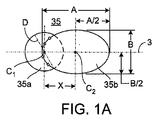
図1Aに概略的に示すように、図1の連結孔35は、第1の実質上円形の部分35aと、第2の細長い部分35bとを含むことができる。円形部分35aと細長い部分35bは互いに重なり合い、したがって互いに連通している。別の実装形態では、連結孔は、2つの実質上円形の部分を含むことができ、これらの円形部分はそれぞれ互いに重なり合い、互いに連通している。円形部分35aの周囲または外周部は、第1の中心点C1および直径Dを画定する。細長い部分35bの周囲または外周部は、第2の中心点C2を画定する。細長い部分35bの外周部はまた、長さまたは長軸Aと、長軸Aに対して実質上垂直な幅または短軸Bとを画定する。長軸Aは、たとえば骨プレートの長手方向軸3に対して実質上平行とすることができる。さらに、長軸Aは長手方向軸3上に位置することができ、第1の中心点C1および第2の中心点C2は長手方向軸3上に配置することができるが、他の構成も可能である。長軸AはDより大きい。
As shown schematically in FIG. 1A, the
図1Aをさらに参照すると、第1の中心点C1と第2の中心点C2は、互いから距離Xだけ分離される。距離XはD/2とA/2の和より小さい。いくつかの実装形態では、距離Xは、以下の例示的な条件を満たす。
0.5(D/2+A/2)<X<1.0(D/2+A/2)
別の実装形態によれば、直径Dは短軸Bより小さい。直径Dは、以下の条件を満たすことができる。
0.75B≦D≦1.1B
Still referring to FIG. 1A, the first center point C 1 and the second center point C 2 are separated from each other by a distance X. The distance X is less than the sum of D / 2 and A / 2. In some implementations, the distance X satisfies the following exemplary condition.
0.5 (D / 2 + A / 2) <X <1.0 (D / 2 + A / 2)
According to another implementation, the diameter D is smaller than the minor axis B. The diameter D can satisfy the following conditions.
0.75B ≦ D ≦ 1.1B
以下でさらに詳細に論じるように、細長い部分35bは、実質上球形のねじ頭を受けるように構成および寸法設定することができる。細長い部分35bは、インプラント30の上面の方へ開いている凹面で実質上球形のくぼみを有することができる。球形の頭を有する骨ねじのシャフトが細長い部分35b内で偏心して配置されるとき、球形の頭は、くぼみに係合して骨プレートを片寄らせ、骨折を所望の方向に圧迫することができる。
As discussed in more detail below, the
図1を参照すると、第1のセンサ32および第2のセンサ20は、制御ユニット12に結合される。これは、有線または無線で実現することができる。第1のセンサ32および第2のセンサ20は、概略的にX、Y、およびZと呼ばれる3つの平行移動軸ならびに概略的にピッチ、ヨー、およびロールと呼ばれる3つの角度配向に対する各センサの位置を記述するように構成された6自由度のセンサとすることができる。このようにセンサを配置し、各センサの場所および配向を知ることによって、ランドマーク識別子18をインプラント30上のランドマークに対して配置することができる。1つの特定の実装形態では、これらのセンサからの情報により、外科医は、見えない固定孔31にドリルを固定して適切に位置合わせするための手術経路を計画することが可能になる。各センサ32、20は、たとえば、107 Catamount Drive, Milton Vermont, U.S.A.のAscension Technology Corporation、103 Randall Drive, Waterloo, Ontario, CanadaのNorthern Digital Inc.、または40 Hercules Drive, Colchester Vermont, U.S.A.のPolhemusからの6自由度のセンサとすることができる。当然ながら、他のセンサを使用することもできる。
Referring to FIG. 1, the
第1のセンサ32は、インプラント30に取り付けることができる。たとえば、第1のセンサ32は、インプラント30の外面37に取り付けることができる。インプラント30はまた、溝34およびポケット36(図2参照)を含むことができる。溝34およびポケット36は、インプラント30の壁の中に配置される。第1のセンサ32は、インプラント30に取り付けるためのものであり、インプラント30の耐用寿命にわたって患者内に設置することができる。さらに、整形外科インプラントアセンブリ28は、ポケット36および/または溝34を覆うカバー38を含むことができる。カバー38は、インプラント30の外面37と実質上同一平面とすることができる。したがって、インプラント30は、カバー38を受けるための第2の開口39(図2参照)を含むことができる。
The
第1のセンサ32は、通信用のリードおよび電力用のリードにつなぐことができる。リードおよびセンサは、インプラント30に固定することができる。リード50を使用して、第1のセンサ32を制御ユニット12に接続することができる。リード50は、生体適合性のワイアから作ることができる。一例として、リード50は、9609 Indianapolis Road, Fort Wayne, Indiana 46809のFort Wayne Metals Research Products Corp.から入手可能なDFTワイアから作ることができる。DFTは、Fort Wayne Metals Research Products Corp.の登録商標である。第1のコネクタ52を使用して、リード50をインプラント30に対して配置することができる。第2のコネクタ54を使用して、リード50を制御ユニット12または挿入ハンドル40などの別のデバイスに接続することもできる。
The
第1のセンサ32は、エポキシ樹脂、ポリウレタン、ポリメチルメタクリレート、ポリエーテルエーテルケトン、UV硬化性接着剤、シリコーン、および医療グレードのシアノアクリレートを含む様々な剛性の高い接着剤またはポリマーを使用して、ポケット36内に固定することができる。一例として、14 Fortune Drive, Billerica, Massachusetts 01821のEpoxy Technologyから入手可能なEPO-TEK 301を使用することができる。リード50は、同様に溝の内に固定することもできる。これらのタイプの固定方法は、電気的構成要素の性能に悪影響を与えるものではない。その後、インプラント30上にカバー38を配置して、定位置に溶接することができる。たとえば、これらのカバーは、インプラントにレーザ溶接することができる。リード50はまた、溝(図示せず)の中に配置することもでき、溝は、リード50を受け取ってリード50および関連する第1のセンサ32をインプラント30に対して固定の位置で強固かつ機械的に捕獲するための1つまたは複数の部分を含み、これらの部分は溝の長さに沿って断続的な場所に形成されている。
The
モニタ14は、両センサの互いに対する位置をディスプレイで外科医に示すことができるように、第1のセンサ32および第2のセンサ20の位置(たとえば、場所および/または配向)を表示するように構成することができる。制御ユニット12は、位置データを有線または無線のいずれかでユーザインターフェースに送ることができ、ユーザインターフェースは、ランドマーク識別子18およびインプラント30の相対的な位置をモニタ上に図示することができる。モニタ14上に表示される図は、外科医がユーザインターフェースをランドマーク識別子18の延長として視覚化することができるように、ランドマーク識別子18に対して配向させることができる。ユーザインターフェースはまた、外科医がモニタと手術領域を同時に見ることができるように配向させることができる。
The
挿入ハンドル40は、整形外科インプラントアセンブリ28の設置のために使用することができ、またリードを第1のセンサ32から経路設定するために使用することもできる。たとえば、挿入ハンドル40は、インプラント30と制御ユニット12との間で通信リードと電力リードの両方を経路設定することができる。
The insertion handle 40 can be used for placement of the
図1では、ランドマーク識別子18と挿入ハンドル40はそれぞれ、センサ20、32から制御ユニット12へデータを無線で伝送するための通信モジュール21、25を含むが、有線通信などの他の方法を使用することもできる。第2のコネクタ54は、通信モジュール25内へプラグ接続される。別法として、以下でより詳細に説明するように、インプラント30および挿入ハンドル40は、構成要素が組み立てられたときに第1のセンサ32が通信モジュール25に接続されるような接続を形成する噛合式の電気接点を有することができる。
In FIG. 1, the
インプラント30は、無線通信用の通信回路およびアンテナを含むことができる。第1のセンサ32および/または通信回路に対する電力は、挿入ハンドル40内に位置決めすることができる。たとえば、電力を第1のセンサ32および/または他の電子機器に伝達するための電池を挿入ハンドル40内に配置することができる。別法として、通信回路、アンテナ、および電池を挿入ハンドル40内に配置することができ、これらをそれぞれ第1のセンサ32につなぐことができる。さらに別の実装形態では、インプラント30は、誘導により通信回路に電力を供給して第1のセンサ32からのデータを通信するためのコイルを含むことができる。電源は、単一電力モードとすることができ、またはデュアルモードAC/DCとすることができる。
The
通常の使用の際には、整形外科インプラントアセンブリ28は、患者内に設置される。たとえば、体内に固定する場合、髄内ネイルは髄内管内に配置される。任意選択で、ユーザは、髄内ネイルの近位端部を最初にロックするために、ねじなどの貫通要素を使用することができる。操作者は、ランドマーク識別子18および第1のセンサ32を使用してランドマークを識別する。たとえば、髄内ネイルを固定する場合、外科医は、ランドマーク識別子18を使用して見えない貫通孔31を識別し、貫通要素を配置するための孔31を穿孔する。
In normal use, the
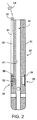
図2は、図1に示すインプラント30をさらに示す。インプラント30は、第1のセンサ32、長手方向の溝34、ポケット36、カバー38、および第2の開口39を含む。インプラント30はまた、外面37を有する。カバー38は、たとえば金またはチタン箔から構成することができる。インプラント30は、カニューレ挿入42を画定する内面41を含むことができる。
FIG. 2 further shows the
図3は、図1のランドマーク識別子18および磁界生成器16の機能とドリルスリーブまたはドリルガイド116などの取外し可能な構成要素とを組み合わせてシステム10内で使用できる手持ち式のランドマーク識別子110にしたランドマーク識別子の代替実装形態を示す。手持ち式のランドマーク識別子110は、筐体113内に電磁界生成器110aを含み、電磁界生成器110aは、適した1つまたは複数の電磁界を生成する1つまたは複数の誘導コイルまたは他の要素を含む。生成された電磁界は、センサ32などの1つまたは複数の電磁センサによって検出することができ、これらのセンサの出力に基づいて、ランドマーク識別子110に対するセンサの位置(場所および配向を含む)を確定することができる。
FIG. 3 illustrates a
電磁界生成器110aは、耐オートクレーブ性材料内またはその上に取り付けられ、容易に殺菌できる耐オートクレーブ性の筐体本体113内にカプセル化される。筐体本体113は結合部材112を含み、結合部材112は、本体内部および筐体113を通過して、鋸歯状の先端部116aを有するドリルガイド116などの1つもしくは複数の取付け可能な構成要素、またはねじ回しスリーブもしくは外科医によって選択される他のドリルスリーブなどの他の適した器具に取外し可能に係合する。筐体本体113は、シリコーン材料のオーバーモールドなどの耐オートクレーブ性材料から形成された第1のカバーリング113aを含み、また、筐体113の外縁部に追加の保護もしくは絶縁層、または審美的な層を提供する第2のカバーリング113bを含むこともできる。第2のカバーリング113bは、第1のカバーリング113aに類似の、または第1のカバーリング113aとは異なる、耐オートクレーブ性材料から形成することができる。
The
ランドマーク識別子110は、電力および制御信号を受け取って電磁界生成器110aの動作を制御するために、制御ユニット12などの処理装置もしくは制御ユニット、またはモニタ14(図1)の一部として含まれる制御ユニットに対する有線または無線リンクを含むことができる。たとえば、ランドマーク識別子110は、制御ユニットまたはモニタ14への接続を提供するケーブル111を含むことができる。
The
図1に示すランドマーク識別子18とは異なり、手持ち式のランドマーク識別子110は、ランドマーク識別子110内でグローバル座標基準系の原点(電磁界が生成される領域)を画定できるため、センサ20を必要としない。たとえば、グローバル座標基準系の1つの軸は、ドリルスリーブ116または他の構成要素の長手方向軸とすることができる。その状況では、グローバル座標基準系の他の2つの軸は、その長手方向軸に直交し、かつ互いに直交する平面によって画定することができる。ランドマーク識別子110内へ磁界生成器を組み込む利点には、磁界生成器の寸法がより小さくなることが含まれる。それは、磁界生成器を局所的な作業空間(たとえば、ねじを配置するためにターゲティングできるインプラント孔などのランドマークを含むことができる領域)に入れることができ、したがって必要な電磁界がより小さくなるためである。さらに、ランドマーク識別子110を使用することで、脛骨および大腿骨ネイルの挿入中に適切な遠位ねじ配置を実現するために使用されてきた放射線放出による透視法の「cアーム」など、貫通要素のターゲティングのためのX線デバイスの必要を低減させ、またはなくすことができる。
Unlike the
ランドマーク識別子110の有用な範囲は、ランドマーク識別子110の作業体積と呼ばれるランドマーク識別子110の周りの3次元領域である。作業体積の寸法および形状は、電磁界生成器110aによって生成される電磁界の特性に基づいており、ターゲティング精度の必要に基づいてより大きくまたはより小さくなるように修正することができる。たとえば、髄内ネイル内の孔をターゲティングするときは、孔が骨の内側に隠れているため、高い精度を有することが望ましいことがある。さらに、所望の圧迫量を実現するために連結孔またはスロット孔をターゲティングするときも、高い精度を有することが望ましいことがある。いくつかの実装形態では、精度を増大させる結果、作業体積はより小さくなる。いくつかの骨プレート内で1つの孔をターゲティングする場合、骨プレートの孔の場所が骨の外側にあり、その孔を露出させてその場所を視覚的に確認することができるため、あまり高い精度を有する必要はないことがある。その結果、作業体積は、髄内ネイルでターゲティングする適用例より、はるかに大きくすることができる。作業体積をより大きくすることで、作業体積内でより多数の孔をターゲティングすることが可能になる。いくつかの実装形態では、作業体積は、ランドマーク識別子110を取り囲む体積である。たとえば、ランドマーク識別子110は、作業体積内の概ね中心に配置することができ、骨プレートの孔のターゲティングなどのいくつかの実装形態に対する作業体積は、幅約50cm以上および深さ約40cm以上に及ぶことができ、ランドマーク識別子110から約5cmの距離を隔てたところに配置することができる。たとえば、ドリルスリーブは通常、作業体積内に確実に位置決めされるように、5cmを超える長さを有する。しかし、当業者には理解されるように、手術的な処置および機器の構成に基づいて、複数の作業体積値が実現可能である。
A useful range for the
図4を参照すると、ターゲティングシステム200は、制御ユニット210と、ランドマーク識別子110と、骨プレート300などの整形外科インプラントに結合された挿入ハンドル220とを含む。骨プレート300は、治癒処理中に骨部分に対する位置合わせ、圧迫、および支持を提供するために、折れた骨に取り付けることができる。他の例では、システム200を使用してターゲティングできる整形外科デバイスには、髄内ネイル、骨プレート、人工関節構成要素、および外部の固定デバイスが含まれる。さらに、ランドマーク識別子110が示されているが、ターゲティングシステム200はまた、図1のランドマーク識別子18などのランドマーク識別子とともに使用することもできる。
Referring to FIG. 4, the targeting
骨プレート300は、貫通孔331および連結孔335などの複数のランドマークを含む。他のランドマークは、構造、空隙、ボス、チャネル、戻り止め、フランジ、溝、部材、区画、ステップ、開口、口径、空胴、ディンプル、ダクト、間隙、ノッチ、オリフィス、通路、スリット、孔、スロット、および細長い孔または細長いスロットを含むことができる。これらのランドマークはまた、可変角度の孔、可変角度のロック孔、もしくは固定角度のロック孔、またはこれらのタイプの孔の組合せを含むことができる。
The
挿入ハンドル220を使用して、患者内への移植中に骨プレート300を操作することができる。挿入ハンドル220は骨プレート300に取外し可能に結合され、その結果、挿入ハンドル220は、移植中に骨プレート300を案内することができ、次いで移植が完了した後に骨プレート300から取り外すことができる。たとえばドリルガイド、ポスト、または他の適した手段など、移植中に骨プレート300を操作する他の方法を使用することもでき、それらは当業者の知識の範囲内である。
The insertion handle 220 can be used to manipulate the
挿入ハンドル220は、骨プレート300に対して固定の位置で骨プレート300に結合される。挿入ハンドル220は、ランドマーク識別子110によって生成される電磁界に応答する、図1のセンサ32に類似の電磁界センサ32を含む。センサ32は、挿入ハンドル220の既知の固定位置で挿入ハンドル220に取り付けられる。したがって、挿入ハンドル220が骨プレート300に取り付けられているとき、骨プレート300に対するセンサ32の位置は6自由度で分かり、センサ32は、貫通孔331および連結孔335などのランドマークに対して既知の場所および配向で配置される。本明細書で前述した方法のいずれかを使用して、骨プレート300上の既知の位置にセンサ32を取り付ける、または骨プレート300にセンサ32を結合するなど、センサ32の位置が6自由度すべてで分かるようにセンサ32を骨プレート300に取り付け、または結合する他の手段が知られており、それらを用いることができる。
The insertion handle 220 is coupled to the
1つまたは複数の自由度で挿入ハンドル220上のセンサ32の位置が当初は知られていない場合、センサ32は、骨プレート300のランドマークまたは挿入ハンドル220の既知のランドマークに対して既知の場所および配向で骨プレート300に取り付けられた第2のセンサ(図示せず)を使用して較正することができる。別法として、ランドマーク識別子110は、骨プレート300のランドマークまたは挿入ハンドル220の既知のランドマークに対して既知の場所および配向で、骨プレート300に取り付けることができる。いくつかの実装形態では、挿入ハンドル220のセンサ32は、挿入ハンドル220を骨プレート300に取り付けたときに骨プレート300のランドマークに対するセンサ32の位置が6自由度で分かるように事前に較正された状態で出荷することができる。
If the position of the
移植処理中およびその後、ランドマーク、具体的には骨プレート300の連結孔335内などのランドマーク内の位置に対するドリルビット、ピン、ねじ、または他のデバイスなどの器具の精密な場所および配向を知る必要があることがある。整形外科インプラント内に形成される典型的な丸い孔とは異なり、連結孔335は、180度以上ねじ切りされた円形部分(図1Aの35a)に結合された細長い部分(図1Aの35b)を含み、細長い部分の中心点と円形部分の中心点との間の距離は、半径(円形部分)と長半径(細長い部分)との和より小さくすることができる。しかし、これらのランドマークは組織によって覆われていることがあり、場所を特定するのが困難になることがある。さらに、器具の場所および/またはインプラントもしくはランドマークに対する器具の角度を確定するための治具または他の手段では、確定するのが困難で時間がかかることがあり、所望の精度を提供することができないことがある。
During and after the implantation process, the precise location and orientation of the instrument, such as a drill bit, pin, screw, or other device, relative to a landmark, specifically a location within the landmark, such as within the
さらに、骨プレートの場合、外科医は、変形可能な頭を有するロックねじまたはねじを円形の孔の中に配置してプレートを骨にロックする前に、連結孔335の細長い部分内のたとえば圧迫タイプのねじの特定の場所に基づいて、どれだけの圧迫を実現することができるかを知りたいと考えることが多いはずである。ランドマーク識別子110を制御ユニット210の処理装置上で機能するソフトウェアとともに使用して、骨プレート300の既知のパラメータ、骨プレート300上のランドマークの場所、骨折の場所およびタイプ、ならびに関連するセンサ32の既知の場所および自由度に基づいて、たとえば連結孔335の細長い部分または骨プレート300内の細長いスロット内で、所定の点をターゲティングすることができる。
Further, in the case of a bone plate, the surgeon may place a locking screw or screw with a deformable head in the circular hole to lock, for example, the compression type in the elongated portion of the
連結孔335内に器具を配置するために選択された点に応じて、制御ユニット210はまた、制御ユニット210のユーザインターフェース210aを介して、選択されたプレート300とともに特定の骨折に対して達成された圧迫量の指示(たとえば、数値、図表、または他の指示)を提供することができ、それによって外科医は、圧迫量を増大または低減させて治癒および回復処理を最適化することが可能になる。したがって、ランドマークが露出されているとき、またはランドマークが組織によって覆われているときに、ランドマーク識別子110を制御ユニット210とともに使用して、ランドマーク、具体的には連結孔335の細長い部分内の特有の点などのランドマーク内の特有の場所をターゲティングし、ランドマーク内に配置される貫通要素の位置、および骨圧迫などの達成可能な特性を確定することができる。
Depending on the point selected to place the instrument within the
システム200の制御ユニット210は、ランドマーク識別子110の動作を制御し、センサ32から入力を受け取る。制御ユニット210はまた、システム200の操作者に情報を提供するユーザインターフェース210aを含む。制御ユニット210は、センサ32からの入力および電磁界生成器110aを制御する信号に関する情報に基づいて、骨プレート300などの整形外科インプラントのランドマークに対するセンサ32の場所および配向を確定するように構成された処理装置を含む。この確定は、センサ32とランドマークとの間の既知の位置関係、およびセンサ32に対して確定されたランドマーク識別子110の位置に基づいて行われる。
The
制御ユニット210は、骨プレート300などの整形外科インプラントの形状および骨プレート300の特徴の場所に関する事前にプログラムされた情報にアクセスすることができる。特定の実装形態では、制御ユニット210は、骨プレート300の3次元モデル、骨プレート300の寸法、骨プレート300の連結孔335の細長い部分および円形部分の中心点の計算、ならびに骨プレート300内に形成された他の貫通孔またはスロットの位置および寸法など、整形外科インプラントに関する他の情報にアクセスすることもできる。さらに、制御ユニット210は、センサ32の場所に関する情報にアクセスすることもできる。たとえば、上記で論じたように、センサ32は、インプラントに対する位置もしくは構成に取り付けられた事前に選択されたランドマーク、ハンドル、もしくは他の要素に取り付けることができ、またはセンサ32が取り付けられているランドマークに関する情報は、センサ32が取り付けられているランドマークを示すためにユーザがインターフェース210aの一部分に触れることなどによって、制御ユニット210に入力することができる。
The
さらに後述するように、制御ユニット210は、整形外科インプラント300に対して既知の位置に配置されたセンサ32からの信号を受け取る。整形外科インプラント300の各連結孔335は、連結孔335内の2つ以上のターゲティング場所で貫通要素を受けるように画定される。制御ユニット210は、2つ以上のターゲティング場所のうちの第1のターゲティング場所を選択する。選択された第1のターゲティング場所は、たとえば、連結孔335の円形部分の中心点または細長い部分の中心点とすることができる。第1のターゲティング場所は、所望の骨圧迫量をもたらす場所の計算に基づいて場所を識別するユーザ入力、および/または他の入力に基づいて選択することができる。制御ユニット210は、センサ32からの信号に基づいて、第1のターゲティング場所に対するランドマーク識別子110の位置を確定し、たとえばユーザインターフェース上の第1のターゲティング場所に対するランドマーク識別子110の位置を示す。
As will be described further below,
図4および図5A〜5Cを参照すると、ランドマーク識別子110および制御ユニット210を使用して、たとえば骨プレート300の連結孔335内の複数の場所をターゲティングすることができる。第1の位置または場所、たとえば連結孔335の細長い部分335bの中心350(図5A)または円形部分335aの中心360(図5A)をターゲティングするために、ドリルガイド116の先端部116aを患者の皮膚に接触させることなどによって、ランドマーク識別子110は骨プレート300付近に位置決めされる。センサ32がランドマーク識別子110の作業体積内に配置され、電磁界生成器110aが電磁界を生成するとき、制御ユニット210は、ランドマーク識別子110に対するセンサ32の位置を示すセンサ32によって生成された信号を受け取る。センサ32からの信号を使用して、制御ユニット210は、骨プレート300のターゲティングされた連結孔335に対するランドマーク識別子110の位置を確定することができる。制御ユニット210は、ターゲティングされた連結孔335、場合によっては骨プレート300の連結孔335の中心350、360または他の所望の特徴の場所に対するランドマーク識別子110の位置に関する情報を、ユーザインターフェース210a上に出力する。
With reference to FIGS. 4 and 5A-5C, the
ユーザインターフェース210aに基づいて、外科医または他のユーザは、骨プレート300の連結孔335内で選択された位置の真上にドリルガイド116の先端部116aが位置することをインターフェース210aが示す位置に、ランドマーク識別子110を配置することができる。たとえば、いくつかの実装形態では、インターフェース210aは、ドリルガイド116の遠位先端部116aの位置を示す第1の円などの第1の識別子要素244aを含む。したがって、第1の識別子要素244aが、細長い部分335bの中心点350または円形部分335aの中心点360などのターゲティングされた位置に対応してその位置を表すランドマーク要素246aと位置合わせされたとき、インターフェース210aは、連結孔335によって表される中心点350、360のいずれかの真上にドリルガイド116の先端部116aが位置することを示す。インターフェース210aはまた、異なるグラフィカル要素を含むことができ、音声または触覚出力を含むことができる。
Based on the
連結孔335内の所望の位置または場所の位置が分かっているとき、ユーザインターフェース210a上に示されるランドマーク要素246aと第1の識別子要素244aが位置合わせされたときにドリルガイド116の先端部116aの領域内に切開部を作ることなどによって、連結孔335を露出させることができる。次いで、患者の骨および/または連結孔335に、暫定的な固定ピン、ノンロック骨ねじ、ロック骨ねじ、または可変ロック骨ねじを係合することができる。さらに、ドリルまたは他の器具を使用して、上記のファスナのうちの1つまたは複数を受けるための孔を患者の骨の中に生成することができる。次いで、ランドマーク識別子110および制御ユニット210を使用して、骨プレート300内の同じ連結孔335または別のランドマーク内の別の所望の場所にある暫定的な固定ピン、ノンロックねじ、ロック骨ねじ、または可変ロック骨ねじのうちの別の1つに係合することができる。
When the desired location or location of the location within the
図5A〜5Cは、ユーザインターフェース210aの様々な例示的な図を概略的に示す。これらの図は、上記のランドマーク識別子110または18および制御ユニット210を使用して暫定的な固定ピン、ノンロックねじ、ロック骨ねじ、または可変ロック骨ねじなどの固定部材を連結孔335内に配置できるシーケンスを示す。たとえば、図5Aに概略的に示すように、当業者には知られている任意の手段を介してプレートを骨折の片側で骨断片に結合した後、ユーザは、ランドマーク識別子110および制御ユニット210を使用して、最初に連結孔335の細長い部分335bの中心点350から離れた位置「1」にノンロックねじを配置し、プレートを左側へ動かして骨折を圧迫し、次いで連結孔335の円形部分335aの中心点360にある位置「2」にロック骨ねじを配置することができる。
5A-5C schematically illustrate various exemplary views of the
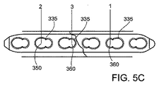
同様に、図5Bは、ユーザがランドマーク識別子110および制御ユニット210を使用して、最初に第1の連結孔335の円形部分335aの中心点360にある位置「1」にロック骨ねじを配置できる第2の実装形態を示す。次いでユーザは、第2の連結孔335の細長い部分335bの中心点350から離れた位置「2」にノンロック圧迫ねじを配置して骨折を圧迫することができ、最後に第2の連結孔335の円形部分335aの中心点360にある位置「3」にロックねじを配置することができる。
Similarly, FIG. 5B shows that the user uses the
図5Cは、ユーザがランドマーク識別子110および制御ユニット210を使用して、最初に第1の連結孔335の円形部分335aの中心点360にある位置「1」にロック骨ねじを配置し、次いで第2の連結孔の細長い部分335bの中心点350から離れた位置「2」にノンロック圧迫ねじを配置して骨折を圧迫できるさらに別の例示的な実装形態を示す。次いでユーザは、ランドマーク識別子110および制御ユニット210を使用して、第3の連結孔335の円形部分335aの中心点360にある位置「3」にロック骨ねじを配置することができる。図5A〜5Cに示すそれぞれの実装形態の結果、圧迫および骨治癒特性をわずかに変動させることができ、したがって、本明細書に記載する実装形態は、治癒および回復を最適化するために複数の異なる選択肢をユーザに提供する。
FIG. 5C shows that the user first uses the
図6は、ユーザインターフェース210aの例示的な実装形態を示し、骨折の制御された圧迫を提供するためにスロットまたは連結孔内の特定の位置でねじ、暫定的なピンなどの固定要素を挿入するには、ランドマーク識別子18、110のうちの1つを制御ユニット210とともにどのように使用できるかを示す。特定の位置は、操作者または制御ユニット210によって最適になるように確定された位置とすることができる。図6を参照すると、骨折60のグラフィカル描写を横断して配置されたユーザインターフェース210a上に、骨プレート300の一部分が示されている。骨プレート300は複数の連結孔335を含み、連結孔335はそれぞれ、円形部分335aおよび細長い部分335bを有する。上記のように、ユーザは、ランドマーク識別子110および制御ユニット210を使用し、上記の技法を使用して、ねじまたは暫定的なピンなどの貫通要素を連結孔335内の様々な場所に配置することができる。
FIG. 6 shows an exemplary implementation of the
図6の例示的な実装形態に示すように、ユーザは最初に、第1の連結孔335の円形部分335aの中心点360にロックねじを配置するように、ランドマーク識別子110および制御ユニット210を使用して位置「1」にロックねじを配置する。ロックねじが位置「1」に着いたのち、ユーザは続いて、圧迫のために中心から離れた位置「2」に概略的に示す第2の連結孔335の細長い部分335b内へ、圧迫タイプのねじを配置することができる。図6の例示的な実装形態に示すように、ユーザが圧迫ねじを位置「2」に配置した場合、ソフトウェアによる計算に基づいて、ねじは骨折60に対して1.5mm圧迫することが可能になる。しかしユーザが骨折60に対してより大きい圧迫またはより小さい圧迫を提供することを望む場合、ユーザには少なくとも2つの選択肢がある。したがって、ねじとプレートの組合せを使用して骨圧迫を実現することができる。
As shown in the exemplary implementation of FIG. 6, the user first sets the
第1の選択肢では、ユーザは、UPの矢印215を押下して圧迫量を増大させ、またはDOWNの矢印217を押下して圧迫量を低減させることができる。一例として、図6に示すように、ユーザがUPの矢印を押下した場合、位置「2」に対するターゲティング線は、ユーザインターフェース210a上の位置を位置「2」から位置「2a」に変更し、連結孔335の細長い部分335b内の締付け部材の場所に対する新しい位置が細長い部分335bの中心の左側へ動いたことをユーザに示す。ターゲットを位置「2」から位置「2a」へ動かすことに加えて、制御ユニット210は、固定部材の新しい位置に対する圧迫量を再計算し、新しい値を(たとえば、2.0mm、2.5mmなど)ユーザに提示する。圧迫のための場所と値はどちらも、整形外科インプラント(ネイル、プレート、ねじなど)の寸法および形状、骨および/または骨折のタイプ、骨折または圧迫の場所、ならびに孔内および/または整形外科インプラントの長さに沿った締付け部材の場所に基づいて変動することが、当業者には明らかなはずである。連結孔の細長い部分または整形外科インプラント内に形成された他の細長いスロット内の様々な位置で達成可能な圧迫の値を提供することで、骨折の圧迫過剰または圧迫不足を制限または防止するのを助け、それによって骨の短縮または癒着不良を回避するのに役立つ。さらに、そのような配置の案内は、スロットまたは細長い部分の縁部から近すぎるまたは遠すぎる位置にファスナが配置されるのを回避するのに役立つ。このような配置は、骨折の圧迫を最小にし、または一切圧迫できなくする可能性がある。
In the first option, the user can press the
第2の選択肢として、ユーザは、たとえばユーザインターフェース210a上で識別子によって示される位置「2」からユーザインターフェース210a上で識別子によって示される位置「2a」へランドマーク識別子を単に動かすことができる。図6では識別子が1つの線として示されているが、識別子は、上記のターゲティング識別子要素のうちの1つもしくは複数とすることができ、または当技術分野で知られている十字形もしくは他のタイプのターゲット要素を含むこともできることが、当業者には理解されよう。ユーザが骨プレート300に対して、より具体的には連結孔335の細長い部分335b内の位置に対してランドマーク識別子110を動かすと、制御ユニット210は、骨折60に加えられる圧迫量の結果を再計算し、ユーザインターフェース210aを介してそれをユーザに提示する。このようにして、どちらの選択肢も、骨プレート300の連結孔335の細長い部分内に貫通要素を選択的に配置することによって圧迫量を最適化する能力をユーザに提供する。最後に、上記のように、ユーザは、圧迫ねじに対する所望の位置を選択した後、ランドマーク識別子110および制御ユニット210を使用して、図6に示す連結孔335の円形部分335a内の位置「3」に追加のロックねじを配置することができる。
As a second option, the user can simply move the landmark identifier from position “2” indicated by the identifier on
ユーザインターフェース210aはまた、操作者が貫通要素を挿入することに加えて処置を実行するのを支援することができる。たとえば、ユーザインターフェース210aは、プレート孔充填デバイスなどの補強要素を空いている孔の中へ移植するための位置を示すことができる。別の例として、ユーザインターフェース210aは、操作者が取り外すべき貫通要素の場所を特定するのを案内することができる。ユーザインターフェース210aは、設置されている貫通要素に対する取外し器具の場所、および特定の貫通要素を取り外すために取外し器具の位置が許容可能であるかどうかを示すことができる。ユーザインターフェース210aは、取外し器具の配向が許容可能であること、たとえば取外し器具が貫通要素の軸に沿って位置合わせされたことを示すことができる。
The
さらに、ユーザインターフェース210aは、どの連結孔335または他の孔が貫通要素で充填されているかを示すことができる。いくつかの実装形態では、操作者は、どの孔および/または連結孔335の部分が占有されているかを示すユーザ入力を提供することができる。それに応答して、制御ユニット210は、占有されている孔または場所を示す。いくつかの実装形態では、制御ユニット210は、貫通要素が設置されると、貫通要素が挿入されている場所を検出することができる。特定の場所に貫通要素が設置されたことを検出した後、制御ユニット210は、特定の場所(たとえば、特定の孔または孔の一部分)が占有されたことをユーザインターフェース210a上に自動的に示すことができる。
Further, the
また、図4を参照すると、ランドマーク識別子18、110および制御ユニット210を使用して、段階的または偏心的な穿孔方法を介して、骨プレート300などの整形外科インプラントの円形または円形状の貫通孔331の中心点から距離を隔てた位置を識別することによって、骨折を圧迫し、各貫通孔内で漸進的な圧迫を提供してターゲットの圧迫の和を得ることもできる。貫通孔331は、全体として参照により本明細書に組み込まれている米国特許第7,905,910号に記載のように、ねじ切りされた孔、ねじ切りされていない孔、またはねじ切りされた孔とねじ切りされていない孔との組合せなどのこれらの組合せを含むことができ、円形、正方形、多角形、またはこれらの任意の組合せとすることができる。使用の際には、そのような整形外科インプラントを用いて、ランドマーク識別子110などのランドマーク識別子および制御ユニット210を使用して、貫通孔331のうちの第1の貫通孔の中心点から距離を隔てた位置を識別し、その位置で達成可能な圧迫値が所望の量より小さい場合、ユーザは、貫通孔331のうちの第2の貫通孔から距離を隔てた第2の位置を識別することができ、ユーザインターフェース210a上に示されているその位置および前の位置で達成可能な圧迫値の和が所望の量である場合、ユーザまたは外科医は、ロックねじを配置してプレートを骨にロックすることを選択することができる。
Referring also to FIG. 4, circular or circular penetration of an orthopedic implant, such as a
上記の特徴に加えて、制御ユニット210のインターフェース210aはまた、骨プレート300に対する器具の許容可能な位置決めを確認するために、骨プレート300、またはたとえば骨プレート300内の連結孔335に対するランドマーク識別子110の現在の角度位置を示すことができる。たとえば、制御ユニット210は、骨プレート300の可変角度のロック孔に対するドリルガイド116の現在の角度を表示することができ、その結果、外科医などの操作者は、患者の骨の中に穿孔された孔が可変角度のロックファスナに対して許容可能な角度をもたらすことを確認することができる。いくつかの実装形態では、インターフェース210aは、ランドマーク識別子110の近位部分を表す第2の円などの第2の識別子要素244bと、第1の識別子要素244aから第2の識別子要素244bへの軸を表す第3の識別子要素244cとを含む。図4に示すように、第1の識別子要素244aと第2の識別子要素244bが互いに接近すると、ランドマーク識別子110の角度は、骨プレート300の孔の中心貫通軸などの基準軸から0度に接近する。したがって、第1の識別子要素244aと第2の識別子要素244bが同心円状であるとき、ランドマーク識別子110は基準軸に対して平行である。
In addition to the features described above, the
制御ユニット210は、整形外科インプラント30または300のランドマークに対するランドマーク識別子110の位置を示す信号を受け取る。この信号は、センサ32から受け取ることができる。センサ32からの信号を使用して、制御ユニット210は、ランドマークに対する器具の位置を確定する。制御ユニット210はまた、この器具の位置を、ランドマークに対するファスナの許容可能な位置範囲などの許容可能な位置範囲と比較する。たとえば、ランドマークは可変角度のロック孔とすることができ、ファスナは、可変角度の孔の中に可変角度でロックするように構成された骨ねじとすることができる。可変角度のロックねじおよび可変角度のロック孔は、所与の処置に対して使用が許容され、または示される、制限された角度範囲を有することができる。別の例として、器具がドリルビットを含むとき、制御ユニット210は、可変角度のロック孔の中心の貫通軸に対するドリルビットの角度を、可変角度のロック孔の許容可能な挿入角度と比較することができる。さらに、特定の医療処置には、ランドマークに対する特定の角度または位置でファスナを挿入することが必要とされることがある。たとえば、外科医または他の個人は、可変角度のロック孔またはノンロック孔に対する第1の角度で特定の骨断片が配置されたことを確定することができる。制御ユニット210を使用して、骨断片をファスナによって捕獲および固定できるように、ランドマーク識別子110が骨断片をターゲティングしたことを識別することができる。
The
いくつかの実装形態では、制御ユニット210は、ランドマークに対するランドマーク識別子110の位置が許容可能であるという表示を、グラフィカルユーザインターフェース210a上に出力する。たとえば、ユーザインターフェース210a上の出力は、ランドマークの軸に対するランドマーク識別子110の角度を表す要素、ランドマークに対するランドマーク識別子110の許容可能な位置を表す1つまたは複数の要素、ランドマークに対するランドマーク識別子110の許容可能でない位置を表す1つまたは複数の要素、ランドマークの軸に対するランドマーク識別子110の角度の数値表現、許容可能なファスナの最大挿入角度の数値表現、ランドマーク識別子110の現在の位置が許容可能であることを示す要素、可変角度または可変角度ロックねじの許容可能な円錐形の範囲のグラフィカル表現、およびランドマーク識別子110の現在の位置が許容可能でないことを示す要素などの1つまたは複数の要素を含むことができる。
In some implementations, the
いくつかの実装形態では、制御ユニット210は、手術の配向が患者にとってリスクになるかどうかを確定する。たとえば、制御ユニット210は、整形外科インプラント30または300に対するランドマーク識別子110の現在の位置が許容可能でない外傷リスクを患者にもたらすかどうかを確定することができる。たとえば、遠位半径プレート内に遠位ねじを設置したとき、制御ユニット210は、ランドマーク識別子110の位置が許容可能でない関節表面の破断のリスクを提示すると確定されたことを操作者に警告することができる。これらの技法を使用して、遠位半径プレート、近位脛骨プレート、遠位脛骨プレート、および他の整形外科インプラント30または300を配置したときに、貫通要素の穿孔または挿入のために解剖学上許容可能な位置へ、操作者を案内することができる。
In some implementations, the
制御ユニット210は、処置のために許容可能な位置決め範囲を示すデータにアクセスすることができる。制御ユニット210は、様々な異なる処置および異なる整形外科インプラント30または300に対する許容可能な位置決めに関するデータにアクセスすることができる。制御ユニット210は、整形外科インプラント30または300に対するランドマーク識別子110の位置を、特定の処置および特定の整形外科インプラント30または300に対応する許容可能な位置決め範囲と比較する。制御ユニット210が、ランドマーク識別子110の位置が所定の許容可能領域外にあると確定した場合、外傷または望ましくない結果を避けるようにシステムの操作者に警告することができる。制御ユニット210が、ランドマーク識別子110の位置が許容可能であると確定した場合、制御ユニット210は、その位置が許容可能であるという確認を提供することができる。
The
特に大きい整形外科インプラント30が使用されるときなどのいくつかの実装形態では、整形外科インプラント30のいくつかのランドマークが、第1のセンサ32を使用してターゲティングするには第1のセンサ32から遠すぎることがある。そのような実装形態では、とりわけ、第1のセンサ32から遠すぎるまたは作業体積の外にあるランドマークのターゲティングで使用するために第1のセンサ32によって共用される作業体積内の場所で、整形外科インプラント30に第2のセンサ(図示せず)を取り付けることができる。第2のセンサは、小さい切開部を通じて整形外科インプラント30に取り付けることができ、この切開部は、整形外科インプラント30の固定を実現するのに必要な切開部の数および寸法を低減させるようにランドマーク識別子および第1のセンサ32を使用して作られたものとすることができる。
In some implementations, such as when a particularly large
他の実装形態では、ターゲティングシステムは、本体部分または折れた骨の下に配置された大きく平坦な磁界生成器を含む。また、ターゲティングシステムは2つのセンサを含み、たとえば、一方のセンサはインプラントに結合され、他方のセンサはドリルスリーブに結合される。生成された磁界が、システムとともに使用される最も大きいインプラントの体積より大きい場合、プレートのランドマークのすべてをターゲティングするのに追加のセンサは必要ない。 In other implementations, the targeting system includes a large flat magnetic field generator disposed under the body portion or broken bone. The targeting system also includes two sensors, for example, one sensor is coupled to the implant and the other sensor is coupled to the drill sleeve. If the generated magnetic field is larger than the volume of the largest implant used with the system, no additional sensors are required to target all of the plate landmarks.
複数の実装形態および代替形態について説明してきた。それにもかかわらず、本開示の精神および範囲から逸脱することなく様々な修正を加えることができることが理解されるであろう。たとえば、図3のランドマーク識別子110に関して様々な使用方法を上述したが、これらの方法はまた、図1のランドマーク識別子18を使用して実施することもできることを理解されたい。さらに、システムの多数の特徴について説明したが、本明細書に記載するシステムおよび方法はまた、それぞれ全体として参照により本明細書に組み込まれている、国際特許出願公開第WO2008/106593号および第WO2009/108214号ならびに米国特許出願第12/758,747号および第12/768,689号に記載のランドマーク識別子、センサ、および制御ユニットに従って使用することもできる。したがって、他の実装形態も以下の特許請求の範囲の範囲内である。
A number of implementations and alternatives have been described. Nevertheless, it will be understood that various modifications can be made without departing from the spirit and scope of the disclosure. For example, although various methods of use have been described above with respect to the
3 長手方向軸
10 システム
12 制御ユニット
14 モニタ
16 磁界生成器
18 ランドマーク識別子
20 センサ
21 通信モジュール
22 鋸歯状の先端部
24 管
25 通信モジュール
26 ハンドル
28 整形外科インプラントアセンブリ
30 インプラント
31 貫通孔
32 センサ、電磁界センサ
33 スロット孔
34 溝
35 連結孔
35a 円形部分
35b 細長い部分
36 ポケット
37 外面
38 カバー
39 第2の開口
40 挿入ハンドル
41 内面
42 カニューレ挿入
50 リード
52 第1のコネクタ
54 第2のコネクタ
60 骨折
110 手持ち式のランドマーク識別子
110a 電磁界生成器
111 ケーブル
112 結合部材
113 筐体
113a 第1のカバーリング
113b 第2のカバーリング
116 ドリルガイド
116a 鋸歯状の先端部
200 ターゲティングシステム
210 制御ユニット
210a ユーザインターフェース
215 UPの矢印
217 DOWNの矢印
220 挿入ハンドル
244a 第1の識別子要素
244b 第2の識別子要素
244c 第3の識別子要素
246a ランドマーク要素
300 骨プレート
331 貫通孔
335 連結孔
335a 円形部分
335b 細長い部分
350 中心
360 中心
A 長軸
B 短軸
C1 第1の中心点
C2 第2の中心点
D 直径
X 距離
3 Longitudinal axis
10 system
12 Control unit
14 Monitor
16 Magnetic field generator
18 Landmark identifier
20 sensors
21 Communication module
22 Serrated tip
24 tubes
25 Communication module
26 Handle
28 Orthopedic implant assembly
30 implants
31 Through hole
32 sensors, electromagnetic field sensors
33 Slot hole
34 Groove
35 Connecting hole
35a round part
35b elongated part
36 pockets
37 Exterior
38 Cover
39 Second opening
40 Insert handle
41 Inside
42 Cannula insertion
50 leads
52 First connector
54 Second connector
60 Fractures
110 Handheld landmark identifier
110a Electromagnetic field generator
111 cable
112 coupling members
113 housing
113a 1st cover ring
113b Second cover ring
116 Drill Guide
116a Serrated tip
200 targeting system
210 Control unit
210a User interface
215 UP arrow
217 down arrow
220 Insert handle
244a First identifier element
244b Second identifier element
244c Third identifier element
246a landmark elements
300 bone plates
331 Through hole
335 Connecting hole
335a round part
335b elongated part
350 center
360 center
A Long axis
B short axis
C 1 1st center point
C 2 2nd center point
D diameter
X distance
Claims (12)
整形外科インプラントに対して既知の位置に配置された磁気センサから信号を受け取り、整形外科インプラントが、貫通要素を受ける孔を画定し、前記孔が、前記孔の中の2つ以上のターゲティング場所で貫通要素を受けるように画定されており、
前記2つ以上のターゲティング場所のうちの第1のターゲティング場所を選択し、
前記信号に基づいて、前記第1のターゲティング場所に対するランドマーク識別子の位置を確定し、且つ
前記第1のターゲティング場所に対する前記ランドマーク識別子の前記位置を示すように構成されており、
前記第1のターゲティング場所を選択することが、
骨圧迫量を示す情報にアクセスすることと、
貫通要素の挿入により骨圧迫が生じる場所を前記第1のターゲティング場所として選択することと
を含む、制御ユニット。 A control unit for targeting landmarks of an orthopedic device, the control unit comprising:
It will receive a signal from the magnetic sensor located at a known position relative to the orthopedic implant, orthopedic implant, and defines an aperture for receiving the penetrating element, wherein the hole is more than one targeting location in said bore in are defined to receive the penetrating element,
Selecting a first targeting location of the two or more targeting locations ;
Based on the signal, to determine the position of the landmark identifier for the first targeting location is configured and to indicate the position of the landmark identifier for the first targeting location,
Selecting the first targeting location;
Accessing information indicating the amount of bone compression;
Selecting a location where bone compression occurs due to insertion of a penetrating element as the first targeting location;
Including control unit .
前記整形外科インプラントの構造に関する情報にアクセスすることと、
前記整形外科インプラントに対する前記磁気センサの前記位置に関する情報にアクセスすることとを含み、
前記第1のターゲティング場所に対する前記ランドマーク識別子の前記位置を確定することが、前記整形外科インプラントの前記構造および前記整形外科インプラントに対する前記磁気センサの前記位置に関する前記情報にさらに基づいて行われる、
請求項1に記載の制御ユニット。 Determining the location of the landmark identifier relative to the first targeting location based on the signal;
Accessing information regarding the structure of the orthopedic implant;
Accessing information regarding the position of the magnetic sensor relative to the orthopedic implant;
Determining the position of the landmark identifier relative to the first targeting location is further based on the information regarding the structure of the orthopedic implant and the position of the magnetic sensor relative to the orthopedic implant;
The control unit according to claim 1.
前記第2のターゲティング場所に対する前記ランドマーク識別子の前記位置を示すことと
をさらに含む、請求項1に記載の制御ユニット。 Determining a location of the landmark identifier relative to a second targeting location of the two or more targeting locations based on the signal ;
The control unit of claim 1, further comprising indicating the location of the landmark identifier relative to the second targeting location.
前記第2のターゲティング場所に対する前記ランドマーク識別子の前記位置を示すことが、ロックファスナを設置するための場所を示すことを含む、
請求項4に記載の制御ユニット。 Indicating the location of the landmark identifier relative to the first targeting location includes indicating a location for installing a non-locking fastener;
Indicating the location of the landmark identifier relative to the second targeting location includes indicating a location for installing a lock fastener;
The control unit according to claim 4.
前記第2のターゲティング場所に対する前記ランドマーク識別子の前記位置を示すことと
をさらに含む、請求項1に記載の制御ユニット。 Determining a position of the landmark identifier relative to a second targeting location in a second hole based on the signal ;
The control unit of claim 1, further comprising indicating the location of the landmark identifier relative to the second targeting location.
ユーザ入力を受け取ることと、
前記ユーザ入力に基づいて前記第1のターゲティング場所を選択することと
を含む、請求項1に記載の制御ユニット。 Selecting the first targeting location;
Receiving user input;
The control unit of claim 1, comprising selecting the first targeting location based on the user input.
貫通要素を受けるための2つ以上のターゲティング場所を画定する少なくとも1つの孔を画定する整形外科インプラントであって、前記2つ以上の場所のうちの少なくとも1つに対して既知の場所に配置された磁気センサを有する整形外科インプラントと、
ランドマーク識別子と、
制御ユニットとを備え、前記制御ユニットが、
前記2つ以上の場所のうちの1つをターゲット場所として選択し、
前記磁気センサから信号を受け取り、
受け取った前記信号に基づいて前記ターゲット場所に対する前記ランドマーク識別子の位置を確定し、
前記ターゲット場所に対する前記ランドマーク識別子の前記位置を示すように構成されており、
第1のターゲティング場所を選択することが、
骨圧迫量を示す情報にアクセスすることと、
貫通要素の挿入により骨圧迫が生じる場所を前記第1のターゲティング場所として選択することと
を含む、システム。 An electromagnetic field generator;
An orthopedic implant defining at least one hole defining two or more targeting locations for receiving a penetrating element, wherein the orthopedic implant is located at a known location relative to at least one of the two or more locations. An orthopedic implant having a magnetic sensor;
A landmark identifier,
A control unit, the control unit comprising:
Selecting one of the two or more locations as a target location;
Receiving a signal from the magnetic sensor;
Determining the location of the landmark identifier relative to the target location based on the received signal;
Configured to indicate the location of the landmark identifier relative to the target location ;
Selecting the first targeting location
Accessing information indicating the amount of bone compression;
Selecting a location where bone compression occurs due to insertion of a penetrating element as the first targeting location;
Including the system.
Applications Claiming Priority (3)
| Application Number | Priority Date | Filing Date | Title |
|---|---|---|---|
| US201161483228P | 2011-05-06 | 2011-05-06 | |
| US61/483,228 | 2011-05-06 | ||
| PCT/US2012/036320 WO2012154496A2 (en) | 2011-05-06 | 2012-05-03 | Targeting landmarks of orthopaedic devices |
Publications (3)
| Publication Number | Publication Date |
|---|---|
| JP2014519870A JP2014519870A (en) | 2014-08-21 |
| JP2014519870A5 JP2014519870A5 (en) | 2015-06-25 |
| JP6109816B2 true JP6109816B2 (en) | 2017-04-05 |
Family
ID=47139898
Family Applications (1)
| Application Number | Title | Priority Date | Filing Date |
|---|---|---|---|
| JP2014509440A Active JP6109816B2 (en) | 2011-05-06 | 2012-05-03 | Orthopedic device landmark targeting |
Country Status (9)
| Country | Link |
|---|---|
| US (1) | US9526441B2 (en) |
| EP (1) | EP2709542B1 (en) |
| JP (1) | JP6109816B2 (en) |
| CN (1) | CN103635153A (en) |
| AU (2) | AU2012253862B2 (en) |
| BR (1) | BR112013028627A2 (en) |
| CA (1) | CA2834940A1 (en) |
| RU (1) | RU2013153116A (en) |
| WO (1) | WO2012154496A2 (en) |
Families Citing this family (17)
| Publication number | Priority date | Publication date | Assignee | Title |
|---|---|---|---|---|
| US9220514B2 (en) | 2008-02-28 | 2015-12-29 | Smith & Nephew, Inc. | System and method for identifying a landmark |
| US9031637B2 (en) | 2009-04-27 | 2015-05-12 | Smith & Nephew, Inc. | Targeting an orthopaedic implant landmark |
| US8945147B2 (en) | 2009-04-27 | 2015-02-03 | Smith & Nephew, Inc. | System and method for identifying a landmark |
| RU2013153116A (en) * | 2011-05-06 | 2015-06-20 | Смит Энд Нефью, Инк. | TARGETING FOR SIGNIFICANT POINTS OF ORTHOPEDIC DEVICES |
| WO2013087082A1 (en) | 2011-12-14 | 2013-06-20 | Stryker Leibinger Gmbh & Co. Kg | Technique for generating a bone plate design |
| US20140178832A1 (en) * | 2012-12-21 | 2014-06-26 | Anatomage Inc. | System and method for providing compact navigation-based surgical guide in dental implant surgery |
| US9414859B2 (en) * | 2013-04-19 | 2016-08-16 | Warsaw Orthopedic, Inc. | Surgical rod measuring system and method |
| US10314626B2 (en) | 2015-01-16 | 2019-06-11 | DePuy Synthes Procucts, Inc. | Washer plate |
| CN105615973B (en) * | 2016-03-17 | 2016-09-28 | 中国葛洲坝集团中心医院 | Vibration location orthopedic steel plate |
| US11529193B2 (en) | 2017-08-10 | 2022-12-20 | Northern Digital Inc. | Tracking a sensor that includes a ferrofluid |
| US10779892B2 (en) * | 2017-08-10 | 2020-09-22 | Northern Digital Inc. | Tracking a cylindrical opening |
| US11033310B2 (en) * | 2017-08-15 | 2021-06-15 | Gomboc, LLC | Magnetic screw and plate apparatus |
| WO2019245668A1 (en) * | 2018-06-21 | 2019-12-26 | California Institute Of Technology | Surgical alignment by magnetic field gradient localization |
| US11457934B2 (en) * | 2018-07-24 | 2022-10-04 | DePuy Synthes Products, Inc. | Intramedullary nail with wire or magnet for targeting of a bone-anchor locking hole |
| US20200107885A1 (en) * | 2018-10-05 | 2020-04-09 | Acclarent, Inc. | Hollow tube surgical instrument with single axis sensor |
| WO2021154794A1 (en) | 2020-01-28 | 2021-08-05 | Mason Bettenga | Systems and methods for aligning surgical devices |
| US11376044B2 (en) * | 2020-02-28 | 2022-07-05 | Set Point Solutions, LLC | Systems and methods using micro-electromagnets secured to bone structure for stabilization, fixation, and accelerated healing |
Family Cites Families (243)
| Publication number | Priority date | Publication date | Assignee | Title |
|---|---|---|---|---|
| US3219969A (en) | 1960-09-19 | 1965-11-23 | Benjamin L Snavely | Electroacoustic transducer and driving circuit therefor |
| US4353110A (en) | 1980-09-12 | 1982-10-05 | Ellis Richard D | Search and warning light system |
| US4532599A (en) | 1982-08-12 | 1985-07-30 | Eaton Corporation | Quality control method |
| DE3332642A1 (en) | 1983-09-09 | 1985-04-04 | Ortopedia Gmbh, 2300 Kiel | DEVICE FOR DETECTING CROSS HOLES INTRAMEDULLA IMPLANTS |
| CH671873A5 (en) | 1985-10-03 | 1989-10-13 | Synthes Ag | |
| US4794930A (en) | 1986-10-03 | 1989-01-03 | Kabushiki Kaisha Toshiba | Attachment for diagnostic ultrasound probe |
| USD297047S (en) | 1986-12-01 | 1988-08-02 | Hon Edward H | Sensor support plate for use with an external medical monitor device |
| US5251127A (en) | 1988-02-01 | 1993-10-05 | Faro Medical Technologies Inc. | Computer-aided surgery apparatus |
| US5049151A (en) | 1989-12-20 | 1991-09-17 | Durham Alfred A | Magnetic positioner arrangement for locking screws for orthopedic hardward |
| US5127913A (en) | 1991-04-22 | 1992-07-07 | Thomas Jr Charles B | Apparatus and method for implanting an intramedullary rod |
| US5383917A (en) | 1991-07-05 | 1995-01-24 | Jawahar M. Desai | Device and method for multi-phase radio-frequency ablation |
| CA2073266A1 (en) | 1991-07-09 | 1993-01-10 | Mehmet Rona | Distal targeting system |
| US5217009A (en) | 1991-07-10 | 1993-06-08 | Kronberg James W | Compact biomedical pulsed signal generator for bone tissue stimulation |
| US5281224A (en) | 1993-01-05 | 1994-01-25 | Orthofix S.R.L. | Centering means for holes of intramedullary nails |
| US5433720A (en) * | 1992-09-22 | 1995-07-18 | Orthofix S.R.L. | Centering means for holes of intramedullary nails |
| US5361766A (en) | 1993-02-17 | 1994-11-08 | David Nichols | Quick release bone probe and x-ray marker |
| IT1265088B1 (en) | 1993-05-20 | 1996-10-30 | Maurizio Luigi Valsecchi | MAGNETIC DEVICE FOR IDENTIFYING THE POSITION AND DIRECTION OF THE AXIS OF BONE DRILLS IN NAILING TECHNIQUES |
| US5411503A (en) * | 1993-06-18 | 1995-05-02 | Hollstien; Steven B. | Instrumentation for distal targeting of locking screws in intramedullary nails |
| US5417688A (en) | 1993-12-22 | 1995-05-23 | Elstrom; John A. | Optical distal targeting system for an intramedullary nail |
| US5514145A (en) | 1994-05-04 | 1996-05-07 | Durham; Alfred A. | Magnetic positioner arrangement for locking screws for orthopedic hardware |
| US5585783A (en) | 1994-06-28 | 1996-12-17 | Hall; Roger E. | Marker light utilizing light emitting diodes disposed on a flexible circuit board |
| US5580156A (en) | 1994-09-27 | 1996-12-03 | Koito Manufacturing Co., Ltd. | Marker apparatus |
| ITBO950144U1 (en) | 1995-10-13 | 1997-04-14 | Lucio Catamo | ELECTROMAGNETIC PROBE FOR IDENTIFYING METAL VEHICLES AND FOR DISCIMINATING THE RELATIVE HOLES FOR IMPLEMENTING DETAILS |
| IL125755A (en) | 1996-02-15 | 2003-05-29 | Biosense Inc | Catheter calibration and usage monitoring system |
| DE29608071U1 (en) | 1996-05-04 | 1997-09-04 | Synthes Ag | Aiming device for locking the foot area of intramedullary nails |
| CA2225375A1 (en) | 1996-12-23 | 1998-06-23 | Mark Manasas | Alignment guide for insertion of fluted or keyed orthopedic components |
| JP2002513305A (en) | 1997-01-28 | 2002-05-08 | クラウス,ウイリアム,アール. | Target setting device for relatively positioning multiple devices |
| US6106528A (en) | 1997-02-11 | 2000-08-22 | Orthomatrix, Inc. | Modular intramedullary fixation system and insertion instrumentation |
| US5993463A (en) | 1997-05-15 | 1999-11-30 | Regents Of The University Of Minnesota | Remote actuation of trajectory guide |
| US6311082B1 (en) | 1997-11-12 | 2001-10-30 | Stereotaxis, Inc. | Digital magnetic system for magnetic surgery |
| US6157853A (en) | 1997-11-12 | 2000-12-05 | Stereotaxis, Inc. | Method and apparatus using shaped field of repositionable magnet to guide implant |
| US6212419B1 (en) | 1997-11-12 | 2001-04-03 | Walter M. Blume | Method and apparatus using shaped field of repositionable magnet to guide implant |
| US6348058B1 (en) | 1997-12-12 | 2002-02-19 | Surgical Navigation Technologies, Inc. | Image guided spinal surgery guide, system, and method for use thereof |
| US6036696A (en) | 1997-12-19 | 2000-03-14 | Stryker Technologies Corporation | Guide-pin placement device and method of use |
| US5957934A (en) | 1997-12-22 | 1999-09-28 | Uri Rapoport | Method and apparatus for guiding a penetrating tool into a three-dimensional object |
| US6503249B1 (en) * | 1998-01-27 | 2003-01-07 | William R. Krause | Targeting device for an implant |
| US6009878A (en) | 1998-02-02 | 2000-01-04 | Medtronic, Inc. | System for locating implantable medical device |
| US6304091B1 (en) | 1998-02-10 | 2001-10-16 | Immersion Corporation | Absolute position sensing by phase shift detection using a variable capacitor |
| DE19812129B4 (en) | 1998-03-19 | 2005-03-17 | Matthias Wolter | Device for finding locking bores |
| US6081741A (en) | 1998-06-05 | 2000-06-27 | Vector Medical, Inc. | Infrared surgical site locating device and method |
| CA2335867C (en) | 1998-06-22 | 2008-12-30 | Synthes (U.S.A.) | Fiducial matching by means of fiducial screws |
| US6477400B1 (en) | 1998-08-20 | 2002-11-05 | Sofamor Danek Holdings, Inc. | Fluoroscopic image guided orthopaedic surgery system with intraoperative registration |
| US5957836A (en) | 1998-10-16 | 1999-09-28 | Johnson; Lanny L. | Rotatable retractor |
| US6233490B1 (en) | 1999-02-09 | 2001-05-15 | Kai Technologies, Inc. | Microwave antennas for medical hyperthermia, thermotherapy and diagnosis |
| US7549960B2 (en) | 1999-03-11 | 2009-06-23 | Biosense, Inc. | Implantable and insertable passive tags |
| US7575550B1 (en) | 1999-03-11 | 2009-08-18 | Biosense, Inc. | Position sensing based on ultrasound emission |
| US6470207B1 (en) | 1999-03-23 | 2002-10-22 | Surgical Navigation Technologies, Inc. | Navigational guidance via computer-assisted fluoroscopic imaging |
| US6783529B2 (en) | 1999-04-09 | 2004-08-31 | Depuy Orthopaedics, Inc. | Non-metal inserts for bone support assembly |
| US6491699B1 (en) | 1999-04-20 | 2002-12-10 | Surgical Navigation Technologies, Inc. | Instrument guidance method and system for image guided surgery |
| US6890332B2 (en) | 1999-05-24 | 2005-05-10 | Csaba Truckai | Electrical discharge devices and techniques for medical procedures |
| US6162228A (en) | 1999-07-20 | 2000-12-19 | Durham; Alfred A. | Device for magnetically targeting locking holes in orthopedic hardware |
| US7366562B2 (en) | 2003-10-17 | 2008-04-29 | Medtronic Navigation, Inc. | Method and apparatus for surgical navigation |
| US8644907B2 (en) * | 1999-10-28 | 2014-02-04 | Medtronic Navigaton, Inc. | Method and apparatus for surgical navigation |
| US6474341B1 (en) | 1999-10-28 | 2002-11-05 | Surgical Navigation Technologies, Inc. | Surgical communication and power system |
| RU2168201C1 (en) | 1999-11-03 | 2001-05-27 | Супрун Антон Евгеньевич | Computer data input device |
| AU7940900A (en) | 1999-11-10 | 2001-06-06 | Eeg, Ltd. | Method for locating holes in orthopaedic devices |
| EP1255498B1 (en) * | 2000-01-27 | 2005-11-23 | SYNTHES AG Chur | Bone plate |
| US6725080B2 (en) | 2000-03-01 | 2004-04-20 | Surgical Navigation Technologies, Inc. | Multiple cannula image guided tool for image guided procedures |
| GB0014059D0 (en) | 2000-06-09 | 2000-08-02 | Chumas Paul D | Method and apparatus |
| DE20015775U1 (en) | 2000-09-12 | 2002-01-31 | Stryker Trauma Gmbh | bone nail |
| US6575973B1 (en) | 2000-10-26 | 2003-06-10 | Safedrip Ltd. | Self locking intramedullary nail |
| US6718194B2 (en) | 2000-11-17 | 2004-04-06 | Ge Medical Systems Global Technology Company, Llc | Computer assisted intramedullary rod surgery system with enhanced features |
| US6917827B2 (en) | 2000-11-17 | 2005-07-12 | Ge Medical Systems Global Technology Company, Llc | Enhanced graphic features for computer assisted surgery system |
| EP2130511A1 (en) | 2000-11-17 | 2009-12-09 | Calypso Medical, Inc | System for locating and defining a target location within a human body |
| CA2438005A1 (en) | 2001-02-07 | 2002-08-15 | Synthes (U.S.A.) | Device and method for intraoperative navigation |
| US20050043726A1 (en) | 2001-03-07 | 2005-02-24 | Mchale Anthony Patrick | Device II |
| NO20011769D0 (en) | 2001-04-06 | 2001-04-06 | Bjoern Franc Iversen | Device and system for mutual positioning of prosthetic parts |
| JP2002318137A (en) | 2001-04-20 | 2002-10-31 | Mitsutoyo Corp | Scale for displacement measuring device |
| US7717945B2 (en) | 2002-07-22 | 2010-05-18 | Acumed Llc | Orthopedic systems |
| US6636757B1 (en) | 2001-06-04 | 2003-10-21 | Surgical Navigation Technologies, Inc. | Method and apparatus for electromagnetic navigation of a surgical probe near a metal object |
| US20100268285A1 (en) * | 2001-10-18 | 2010-10-21 | Orthoip, Llc | Bone screw system and method for the fixation of bone fractures |
| US7001346B2 (en) | 2001-11-14 | 2006-02-21 | Michael R. White | Apparatus and methods for making intraoperative orthopedic measurements |
| WO2003044556A2 (en) | 2001-11-20 | 2003-05-30 | Integrinautics Corporation | Multiple antenna multi-frequency measurement system |
| US7729742B2 (en) | 2001-12-21 | 2010-06-01 | Biosense, Inc. | Wireless position sensor |
| KR100485896B1 (en) | 2002-01-17 | 2005-04-29 | 조우신 | Device for inserting screws into an intramedullary nail and method thereof |
| US7634306B2 (en) | 2002-02-13 | 2009-12-15 | Kinamed, Inc. | Non-image, computer assisted navigation system for joint replacement surgery with modular implant system |
| US6711431B2 (en) | 2002-02-13 | 2004-03-23 | Kinamed, Inc. | Non-imaging, computer assisted navigation system for hip replacement surgery |
| US7056322B2 (en) * | 2002-03-28 | 2006-06-06 | Depuy Orthopaedics, Inc. | Bone fastener targeting and compression/distraction device for an intramedullary nail and method of use |
| DE10306793A1 (en) | 2002-05-21 | 2003-12-04 | Plus Endoprothetik Ag Rotkreuz | Arrangement and method for the intraoperative determination of the position of a joint replacement implant |
| WO2003105659A2 (en) | 2002-06-17 | 2003-12-24 | Mazor Surgical Technologies Ltd. | Robot for use with orthopaedic inserts |
| EP1550024A2 (en) | 2002-06-21 | 2005-07-06 | Cedara Software Corp. | Computer assisted system and method for minimal invasive hip, uni knee and total knee replacement |
| US7060075B2 (en) | 2002-07-18 | 2006-06-13 | Biosense, Inc. | Distal targeting of locking screws in intramedullary nails |
| US6892090B2 (en) | 2002-08-19 | 2005-05-10 | Surgical Navigation Technologies, Inc. | Method and apparatus for virtual endoscopy |
| US6807446B2 (en) | 2002-09-03 | 2004-10-19 | Celsion Corporation | Monopole phased array thermotherapy applicator for deep tumor therapy |
| US20100228258A1 (en) | 2003-10-03 | 2010-09-09 | Durham Alfred A | Intramedullary nail targeting device |
| AU2003299542B2 (en) | 2002-10-03 | 2009-01-15 | Virginia Tech Intellectual Properties, Inc. | Magnetic targeting device |
| DE60326608D1 (en) | 2002-10-04 | 2009-04-23 | Orthosoft Inc | COMPUTER-ASSISTED HIP SET OF SURGERY |
| CN100485309C (en) | 2002-11-08 | 2009-05-06 | 北京航天峰光电子技术有限责任公司 | Megnetic displacement measurement device |
| US7542791B2 (en) | 2003-01-30 | 2009-06-02 | Medtronic Navigation, Inc. | Method and apparatus for preplanning a surgical procedure |
| HU225838B1 (en) | 2003-02-03 | 2007-10-29 | Sanatmetal Ortopediai Es Traum | An appliance for the determination of the position of medullary cavity nail bores |
| USD527820S1 (en) | 2003-02-25 | 2006-09-05 | Image-Guided Neurologics, Inc. | Fiducial marker |
| US20040243148A1 (en) | 2003-04-08 | 2004-12-02 | Wasielewski Ray C. | Use of micro- and miniature position sensing devices for use in TKA and THA |
| US6747253B1 (en) | 2003-05-07 | 2004-06-08 | The Boeing Company | Method and apparatus for induction heat treatment of structural members |
| WO2005000140A2 (en) | 2003-06-02 | 2005-01-06 | Murphy Stephen B | Virtual trial reduction system for hip arthroplasty and coordinate systems therefor |
| US7559931B2 (en) | 2003-06-09 | 2009-07-14 | OrthAlign, Inc. | Surgical orientation system and method |
| US8057482B2 (en) | 2003-06-09 | 2011-11-15 | OrthAlign, Inc. | Surgical orientation device and method |
| EP1491150A1 (en) | 2003-06-27 | 2004-12-29 | Universite Libre De Bruxelles | Method of acquiring informations in order to insert a locking screw in a hole of a metallic object |
| AU2004260688A1 (en) | 2003-08-01 | 2005-02-10 | Synthes Gmbh | Drill guide assembly for a bone fixation device. |
| US6906300B2 (en) | 2003-08-13 | 2005-06-14 | The Boeing Company | Consolidation device and method |
| US6979807B2 (en) | 2003-08-13 | 2005-12-27 | The Boeing Company | Forming apparatus and method |
| CA2439850A1 (en) | 2003-09-04 | 2005-03-04 | Orthosoft Inc. | Universal method for determining acetabular and femoral implant positions during navigation |
| DE20314742U1 (en) * | 2003-09-24 | 2003-12-04 | Stryker Trauma Gmbh | Aiming device for a locking nail and locking nail |
| US7632294B2 (en) | 2003-09-29 | 2009-12-15 | Promethean Surgical Devices, Llc | Devices and methods for spine repair |
| US7029478B2 (en) * | 2003-09-30 | 2006-04-18 | Depuy Products, Inc. | Method and apparatus for distal targeting of locking screws in intramedullary nails |
| US7862570B2 (en) | 2003-10-03 | 2011-01-04 | Smith & Nephew, Inc. | Surgical positioners |
| CA2538126A1 (en) | 2003-10-06 | 2005-05-06 | Smith & Nephew, Inc. | Modular navigated portal |
| US7835778B2 (en) | 2003-10-16 | 2010-11-16 | Medtronic Navigation, Inc. | Method and apparatus for surgical navigation of a multiple piece construct for implantation |
| US7840253B2 (en) | 2003-10-17 | 2010-11-23 | Medtronic Navigation, Inc. | Method and apparatus for surgical navigation |
| US7397364B2 (en) | 2003-11-11 | 2008-07-08 | Biosense Webster, Inc. | Digital wireless position sensor |
| US7182762B2 (en) | 2003-12-30 | 2007-02-27 | Smith & Nephew, Inc. | Electrosurgical device |
| US20050197569A1 (en) | 2004-01-22 | 2005-09-08 | Mccombs Daniel | Methods, systems, and apparatuses for providing patient-mounted surgical navigational sensors |
| US8574268B2 (en) * | 2004-01-26 | 2013-11-05 | DePuy Synthes Product, LLC | Highly-versatile variable-angle bone plate system |
| FR2865928B1 (en) | 2004-02-10 | 2006-03-17 | Tornier Sa | SURGICAL DEVICE FOR IMPLANTATION OF A TOTAL HIP PROSTHESIS |
| US8046050B2 (en) | 2004-03-05 | 2011-10-25 | Biosense Webster, Inc. | Position sensing system for orthopedic applications |
| DE602004023048D1 (en) | 2004-03-05 | 2009-10-22 | Biosense Webster Inc | Position detection system for orthopedic applications |
| GB0405013D0 (en) | 2004-03-05 | 2004-04-07 | Depuy Int Ltd | Implantable marker instruments and methods |
| CN2698283Y (en) | 2004-03-06 | 2005-05-11 | 孙德修 | Magnetic probe for locked intramedullary nail |
| EP1722705A2 (en) | 2004-03-10 | 2006-11-22 | Depuy International Limited | Orthopaedic operating systems, methods, implants and instruments |
| WO2005096982A1 (en) | 2004-03-31 | 2005-10-20 | Smith & Nephew, Inc. | Methods and apparatuses for providing a reference array input device |
| US20050228270A1 (en) | 2004-04-02 | 2005-10-13 | Lloyd Charles F | Method and system for geometric distortion free tracking of 3-dimensional objects from 2-dimensional measurements |
| EP1593350B1 (en) | 2004-05-05 | 2007-06-13 | BrainLAB AG | Tracking of intramedullary pin |
| ITTO20040292A1 (en) * | 2004-05-06 | 2004-08-06 | Ezio Visentin | CONNECTION BODY INTENDED TO BE INTRODUCED WITHIN A BONE STRUCTURE OF A HUMAN OR ANIMAL BODY AND SYSTEM FOR THE DETECTION OF AT LEAST A REFERENCE POINT PROVIDED IN THE CONNECTION BODY ITSELF. |
| EP1753354B1 (en) | 2004-05-21 | 2010-09-15 | Myers Surgical Solutions, LLC | Fracture fixation and site stabilization system |
| US7294133B2 (en) | 2004-06-03 | 2007-11-13 | Zimmer Technology, Inc. | Method and apparatus for preparing a glenoid surface |
| JP4874970B2 (en) | 2004-06-07 | 2012-02-15 | ジンテス ゲゼルシャフト ミット ベシュレンクテル ハフツング | Orthopedic implant with sensor |
| US8176922B2 (en) | 2004-06-29 | 2012-05-15 | Depuy Products, Inc. | System and method for bidirectional communication with an implantable medical device using an implant component as an antenna |
| EP1761182B1 (en) | 2004-06-30 | 2011-04-06 | Synthes GmbH | Surgical nail |
| US7776055B2 (en) | 2004-07-19 | 2010-08-17 | General Electric Company | System and method for tracking progress of insertion of a rod in a bone |
| US7702379B2 (en) | 2004-08-25 | 2010-04-20 | General Electric Company | System and method for hybrid tracking in surgical navigation |
| US7481815B2 (en) | 2004-09-23 | 2009-01-27 | Synthes (U.S.A.) | Coplanar X-ray guided aiming arm for locking of intramedullary nails |
| US7422582B2 (en) | 2004-09-29 | 2008-09-09 | Stryker Corporation | Control console to which powered surgical handpieces are connected, the console configured to simultaneously energize more than one and less than all of the handpieces |
| WO2006041963A2 (en) | 2004-10-05 | 2006-04-20 | Abdou M S | Devices and methods for inter-vertebral orthopedic device placement |
| US8007448B2 (en) | 2004-10-08 | 2011-08-30 | Stryker Leibinger Gmbh & Co. Kg. | System and method for performing arthroplasty of a joint and tracking a plumb line plane |
| US8128662B2 (en) | 2004-10-20 | 2012-03-06 | Vertiflex, Inc. | Minimally invasive tooling for delivery of interspinous spacer |
| US20060122541A1 (en) | 2004-11-08 | 2006-06-08 | Gregor Tuma | Adjusting the length of the leg |
| AU2005311752A1 (en) | 2004-12-02 | 2006-06-08 | Smith & Nephew, Inc. | Systems for providing a reference plane for mounting an acetabular cup |
| DE602005021249D1 (en) | 2004-12-09 | 2010-06-24 | Stryker Corp | WIRELESS SYSTEM FOR THE PROVISION OF INSTRUMENT AND IMPLANT DATA TO A SURGICAL NAVIGATION DEVICE |
| CA2587986A1 (en) | 2005-01-18 | 2006-07-27 | Traxtal Inc. | Electromagnetically tracked k-wire device |
| WO2006094119A2 (en) | 2005-03-02 | 2006-09-08 | Osteometrix, Llc | Noninvasive methods, apparatus, kits, and systems for intraoperative position and length determination |
| US20100100011A1 (en) | 2008-10-22 | 2010-04-22 | Martin Roche | System and Method for Orthopedic Alignment and Measurement |
| US9295529B2 (en) | 2005-05-16 | 2016-03-29 | Biosense Webster, Inc. | Position tracking using quasi-DC magnetic fields |
| EP1885263A1 (en) | 2005-05-18 | 2008-02-13 | Sonoma Orthopaedic Products, Inc | Minimally invasive actuable bone fixation devices, systems and methods of use |
| CA2607036C (en) | 2005-06-02 | 2013-07-23 | Orthosoft Inc. | Leg alignment for surgical parameter measurement in hip replacement surgery |
| US20060282168A1 (en) | 2005-06-13 | 2006-12-14 | Sherman Jason T | Orthopaedic prosthesis having a superparamagnetic material and associated method |
| WO2007009088A2 (en) | 2005-07-12 | 2007-01-18 | Alfred E. Mann Institute For Biomedical Engineering At The University Of Southern California | Method and apparatus for detecting object orientation and position |
| JP5518335B2 (en) | 2005-08-23 | 2014-06-11 | スミス アンド ネフュー インコーポレーテッド | Telemetric orthopedic implant |
| JP4880264B2 (en) | 2005-08-24 | 2012-02-22 | オリンパス株式会社 | POSITION DETECTION DEVICE AND MEDICAL DEVICE POSITION DETECTION SYSTEM |
| US7774057B2 (en) | 2005-09-06 | 2010-08-10 | Cardiac Pacemakers, Inc. | Method and apparatus for device controlled gene expression for cardiac protection |
| US7835785B2 (en) | 2005-10-04 | 2010-11-16 | Ascension Technology Corporation | DC magnetic-based position and orientation monitoring system for tracking medical instruments |
| US20070093709A1 (en) | 2005-10-26 | 2007-04-26 | Abernathie Dennis L | Surgical navigation markers |
| US20070123873A1 (en) | 2005-10-31 | 2007-05-31 | Czartoski Timothy J | Intramedullary nail with oblique openings |
| US20090216113A1 (en) | 2005-11-17 | 2009-08-27 | Eric Meier | Apparatus and Methods for Using an Electromagnetic Transponder in Orthopedic Procedures |
| US20070167744A1 (en) | 2005-11-23 | 2007-07-19 | General Electric Company | System and method for surgical navigation cross-reference to related applications |
| US20070129629A1 (en) | 2005-11-23 | 2007-06-07 | Beauregard Gerald L | System and method for surgical navigation |
| US8862200B2 (en) | 2005-12-30 | 2014-10-14 | DePuy Synthes Products, LLC | Method for determining a position of a magnetic source |
| BRPI0706605B8 (en) | 2006-01-17 | 2021-06-22 | Endymed Medical Ltd | electrosurgical system employing phase-controlled radiofrequency energy |
| US20070225595A1 (en) | 2006-01-17 | 2007-09-27 | Don Malackowski | Hybrid navigation system for tracking the position of body tissue |
| US7967820B2 (en) | 2006-02-07 | 2011-06-28 | P Tech, Llc. | Methods and devices for trauma welding |
| US7727240B1 (en) | 2006-02-15 | 2010-06-01 | Blake Benton | Method and system for securing an intramedullary nail |
| US8337426B2 (en) | 2009-03-24 | 2012-12-25 | Biomet Manufacturing Corp. | Method and apparatus for aligning and securing an implant relative to a patient |
| US8167823B2 (en) | 2009-03-24 | 2012-05-01 | Biomet Manufacturing Corp. | Method and apparatus for aligning and securing an implant relative to a patient |
| US20070208251A1 (en) | 2006-03-02 | 2007-09-06 | General Electric Company | Transformer-coupled guidewire system and method of use |
| US7358481B2 (en) | 2006-03-06 | 2008-04-15 | Avago General Ip Pte Ltd | Reflective encoder with three-dimensional code carrier |
| US20120209117A1 (en) | 2006-03-08 | 2012-08-16 | Orthosensor, Inc. | Surgical Measurement Apparatus and System |
| EP1836945A2 (en) | 2006-03-20 | 2007-09-26 | Olympus Medical Systems Corp. | Switch mechanism for use in medical apparatuses, and image-pickup device for use in endoscopes |
| US7949386B2 (en) | 2006-03-21 | 2011-05-24 | A2 Surgical | Computer-aided osteoplasty surgery system |
| US7532997B2 (en) | 2006-04-17 | 2009-05-12 | General Electric Company | Electromagnetic tracking using a discretized numerical field model |
| US9364293B2 (en) | 2006-04-28 | 2016-06-14 | Biosense Webster, Inc. | Reduced field distortion in medical tools |
| SI22284A (en) * | 2006-05-17 | 2007-12-31 | AnĹľe KRISTAN | Non-invasive locking of distal openings on intramedular hollow nails in surgery |
| ES2352303T3 (en) | 2006-06-29 | 2011-02-17 | L.R.S. Ortho Ltd. | SYSTEM FOR LOCATING DISTAL HOLES OF AN INTRAMEDULAR NAIL. |
| US7938777B2 (en) | 2006-07-21 | 2011-05-10 | Orthosoft Inc. | Non-invasive tracking of bones for surgery |
| US7594933B2 (en) | 2006-08-08 | 2009-09-29 | Aesculap Ag | Method and apparatus for positioning a bone prosthesis using a localization system |
| US8685034B2 (en) | 2006-08-10 | 2014-04-01 | Stryker Trauma Gmbh | Distal targeting device |
| EP2051647B1 (en) | 2006-08-15 | 2010-12-01 | AO Technology AG | Method and device for computer assisted distal locking of intramedullary nails |
| US8197494B2 (en) | 2006-09-08 | 2012-06-12 | Corpak Medsystems, Inc. | Medical device position guidance system with wireless connectivity between a noninvasive device and an invasive device |
| US8160676B2 (en) | 2006-09-08 | 2012-04-17 | Medtronic, Inc. | Method for planning a surgical procedure |
| US7785330B2 (en) * | 2006-09-11 | 2010-08-31 | Depuy Products, Inc. | Method and apparatus for distal targeting of locking screws in intramedullary nails |
| US8248413B2 (en) | 2006-09-18 | 2012-08-21 | Stryker Corporation | Visual navigation system for endoscopic surgery |
| US7917193B2 (en) | 2006-10-11 | 2011-03-29 | The United States Of America As Represented By The Secretary Of The Air Force | Determining inserted catheter end location and orientation |
| GR1005791B (en) | 2006-10-19 | 2008-01-30 | Ηλιας Παναγιωτοπουλος | Intramedullary nail with incised auxiliary means for fast location of the securing hole with no use of radioscopy |
| EP1968468B1 (en) | 2006-12-15 | 2010-12-29 | AO Technology AG | Device for computer assisted distal locking of intramedullary nails |
| US20080146969A1 (en) | 2006-12-15 | 2008-06-19 | Kurtz William B | Total joint replacement component positioning as predetermined distance from center of rotation of the joint using pinless navigation |
| EP2120744A4 (en) | 2007-01-11 | 2013-05-01 | Anthem Orthopaedics Llc | Percutaneous intramedullary bone repair device and method for using same |
| CN201029876Y (en) | 2007-01-15 | 2008-03-05 | 杭州市萧山区中医院 | Navigation system for bone surgery |
| US7925068B2 (en) | 2007-02-01 | 2011-04-12 | General Electric Company | Method and apparatus for forming a guide image for an ultrasound image scanner |
| US8784425B2 (en) * | 2007-02-28 | 2014-07-22 | Smith & Nephew, Inc. | Systems and methods for identifying landmarks on orthopedic implants |
| CN101621966B (en) * | 2007-02-28 | 2013-06-19 | 史密夫和内修有限公司 | System and method for identifying a landmark |
| WO2009108214A1 (en) | 2008-02-28 | 2009-09-03 | Smith & Nephew, Inc. | System and method for identifying a landmark |
| US8814868B2 (en) * | 2007-02-28 | 2014-08-26 | Smith & Nephew, Inc. | Instrumented orthopaedic implant for identifying a landmark |
| US8821511B2 (en) | 2007-03-15 | 2014-09-02 | General Electric Company | Instrument guide for use with a surgical navigation system |
| US7918853B2 (en) | 2007-03-20 | 2011-04-05 | Smith & Nephew, Inc. | Orthopaedic plate and screw assembly |
| KR20100029235A (en) | 2007-06-08 | 2010-03-16 | 싸이노슈어, 인코포레이티드 | Surgical waveguide |
| WO2009035582A1 (en) | 2007-09-07 | 2009-03-19 | Angiodynamics, Inc. | Implantable access port |
| US20100289491A1 (en) | 2007-09-21 | 2010-11-18 | Dimitry Budker | Radio frequency atomic magnetometer |
| US20090088756A1 (en) | 2007-10-01 | 2009-04-02 | General Electric Company | System and method for securing surgical implant |
| AU2008310269B2 (en) | 2007-10-10 | 2013-12-19 | Orthosoft Ulc | Hip replacement in computer-assisted surgery |
| US8241390B2 (en) | 2007-10-12 | 2012-08-14 | Ajax Tocco Magnethermic Corporation | Semi-liquid metal processing and sensing device and method of using same |
| DE102007049542A1 (en) | 2007-10-16 | 2009-04-23 | Neue Magnetodyn Gmbh | Implantable device, system for generating localized electromagnetic fields in the region of an implant and coil arrangement |
| US9017335B2 (en) * | 2007-11-19 | 2015-04-28 | Blue Ortho | Hip implant registration in computer assisted surgery |
| US9456766B2 (en) * | 2007-11-26 | 2016-10-04 | C. R. Bard, Inc. | Apparatus for use with needle insertion guidance system |
| FR2925671B1 (en) | 2007-12-20 | 2009-12-18 | Michelin Soc Tech | MAGNETOMETRIC DEVICE FOR EVALUATING A PHYSICAL PARAMETER, AND APPLICATION |
| US8301262B2 (en) | 2008-02-06 | 2012-10-30 | Cardiac Pacemakers, Inc. | Direct inductive/acoustic converter for implantable medical device |
| US9220514B2 (en) | 2008-02-28 | 2015-12-29 | Smith & Nephew, Inc. | System and method for identifying a landmark |
| JP2011518022A (en) | 2008-04-21 | 2011-06-23 | ジェイジー・メディカル・プロダクツ・エルエルシー | Light delivery structure for use in intramedullary transillumination device and method for manufacturing the same |
| DE102008023760A1 (en) | 2008-05-15 | 2009-12-03 | Medizin & Service Gmbh | Position and condition determining arrangement for cross hole at intramedullary nail, has two cameras optically connected to markers by geometrical arrangement of markers to derive three 2-dimensional image coordinates |
| CA2729102C (en) | 2008-06-26 | 2014-05-13 | Wayne Anderson | Depth controllable and measurable medical driver devices and methods of use |
| EP2344078B1 (en) | 2008-07-24 | 2018-04-18 | OrthAlign, Inc. | Systems for joint replacement |
| EP2358310B1 (en) | 2008-09-10 | 2019-07-31 | OrthAlign, Inc. | Hip surgery systems |
| WO2010063117A1 (en) | 2008-12-02 | 2010-06-10 | Andre Novomir Hladio | Method and system for aligning a prosthesis during surgery using active sensors |
| US8491599B2 (en) | 2008-12-19 | 2013-07-23 | Lower Extremity Innovations, Llc | Apparatus and method for aiming a surgical tool |
| BRPI1007988A2 (en) | 2009-02-24 | 2016-03-01 | Smith & Nephew Inc | method and apparatus for fai surgeries. |
| US8251994B2 (en) | 2009-04-07 | 2012-08-28 | Tyco Healthcare Group Lp | Vessel sealer and divider with blade deployment alarm |
| WO2010123879A1 (en) * | 2009-04-20 | 2010-10-28 | Virginia Tech Intellectual Properties, Inc. | Intramedullary nail targeting device |
| US20100274253A1 (en) | 2009-04-23 | 2010-10-28 | Ure Keith J | Device and method for achieving accurate positioning of acetabular cup during total hip replacement |
| WO2010124164A1 (en) | 2009-04-23 | 2010-10-28 | Ure Keith J | A device and method for achieving accurate positioning of acetabular cup during total hip replacement |
| EP3682834A1 (en) | 2009-04-27 | 2020-07-22 | Smith & Nephew, Inc | System and method for identifying a landmark |
| US9031637B2 (en) | 2009-04-27 | 2015-05-12 | Smith & Nephew, Inc. | Targeting an orthopaedic implant landmark |
| US8945147B2 (en) * | 2009-04-27 | 2015-02-03 | Smith & Nephew, Inc. | System and method for identifying a landmark |
| CN102892364B (en) * | 2009-10-06 | 2016-03-16 | 史密夫和内修有限公司 | Aim at the mark of orthopaedic instrumentation |
| WO2011050842A1 (en) * | 2009-10-28 | 2011-05-05 | CHIRMAT Sàrl | Device for positioning and adjusting a viewing axis |
| US8816684B2 (en) | 2009-11-09 | 2014-08-26 | Vista Clara Inc. | Noise canceling in-situ NMR detection |
| MX2012005649A (en) | 2009-11-17 | 2012-12-05 | Univ Kingston | Patient-specific guide for acetabular cup placement. |
| US20120029578A1 (en) * | 2010-02-05 | 2012-02-02 | Sean Suh | Bio-Resorbable Capsule Containing Fenestrated Screw System For Osteoporotic Subject |
| DE102010016386A1 (en) | 2010-04-09 | 2011-10-13 | Aesculap Ag | Noninvasive method and apparatus for determining a reference plane of the human pelvis |
| EP2575686B1 (en) * | 2010-06-03 | 2019-10-16 | Smith & Nephew, Inc. | Orthopaedic implants |
| CN103200887B (en) * | 2010-06-07 | 2015-08-26 | 卡波菲克斯整形有限公司 | Composite material bone implant |
| US8444653B2 (en) * | 2010-08-30 | 2013-05-21 | Biomet Manufacturing Corp. | Intramedullary rod implantation system |
| US20120330191A1 (en) * | 2010-09-08 | 2012-12-27 | Urs Hulliger | Intramedullary Rod Tracking |
| US20120091122A1 (en) * | 2010-10-14 | 2012-04-19 | Eaton Corporation | Selective case depth thermo-magnetic processing and apparatus |
| CN103561670B (en) * | 2010-11-01 | 2018-05-22 | 史密夫和内修有限公司 | Aim at the mark of orthopedic device |
| US8951256B2 (en) | 2010-11-23 | 2015-02-10 | University Of Massachusetts | System and method for orienting orthopedic implants |
| US9795412B2 (en) * | 2010-11-30 | 2017-10-24 | Genossis Llc | Bone compression and fixation devices |
| JP2014508549A (en) | 2010-12-17 | 2014-04-10 | アヴェニール メディカル インコーポレイテッド | Method and system for prosthesis alignment during surgery |
| WO2012103169A2 (en) | 2011-01-25 | 2012-08-02 | Smith & Nephew, Inc. | Targeting operation sites |
| EP2667799B1 (en) * | 2011-01-28 | 2016-07-27 | Synthes GmbH | Alignment device for distal targeting |
| JP5881956B2 (en) | 2011-02-28 | 2016-03-09 | 株式会社日立国際電気 | Substrate processing apparatus, semiconductor device manufacturing method, and wafer holder |
| RU2013153116A (en) * | 2011-05-06 | 2015-06-20 | Смит Энд Нефью, Инк. | TARGETING FOR SIGNIFICANT POINTS OF ORTHOPEDIC DEVICES |
| CA2847599C (en) * | 2011-09-16 | 2016-09-06 | Stryker Trauma Gmbh | Intramedullary nail locking hole arrangement |
| AU2012315809B2 (en) | 2011-09-29 | 2017-06-08 | Arthromeda, Inc. | System and method for precise prosthesis positioning in hip arthroplasty |
| US8997362B2 (en) * | 2012-07-17 | 2015-04-07 | Faro Technologies, Inc. | Portable articulated arm coordinate measuring machine with optical communications bus |
| EP3077037B1 (en) * | 2013-12-04 | 2021-11-17 | ReShape Lifesciences Inc. | System for locating intragastric devices |
| TWI538654B (en) * | 2014-03-03 | 2016-06-21 | 國立交通大學 | Locating system for locking hole of intramedullary nail |
| US10912523B2 (en) * | 2014-03-24 | 2021-02-09 | Intuitive Surgical Operations, Inc. | Systems and methods for anatomic motion compensation |
-
2012
- 2012-05-03 RU RU2013153116/14A patent/RU2013153116A/en not_active Application Discontinuation
- 2012-05-03 BR BR112013028627A patent/BR112013028627A2/en not_active Application Discontinuation
- 2012-05-03 WO PCT/US2012/036320 patent/WO2012154496A2/en active Application Filing
- 2012-05-03 US US14/114,940 patent/US9526441B2/en active Active
- 2012-05-03 CN CN201280033510.8A patent/CN103635153A/en active Pending
- 2012-05-03 AU AU2012253862A patent/AU2012253862B2/en not_active Ceased
- 2012-05-03 JP JP2014509440A patent/JP6109816B2/en active Active
- 2012-05-03 CA CA2834940A patent/CA2834940A1/en not_active Abandoned
- 2012-05-03 EP EP12782139.5A patent/EP2709542B1/en active Active
-
2016
- 2016-12-23 AU AU2016277733A patent/AU2016277733A1/en not_active Abandoned
Also Published As
| Publication number | Publication date |
|---|---|
| BR112013028627A2 (en) | 2017-01-24 |
| EP2709542B1 (en) | 2024-04-17 |
| EP2709542A4 (en) | 2015-06-10 |
| RU2013153116A (en) | 2015-06-20 |
| CN103635153A (en) | 2014-03-12 |
| AU2016277733A1 (en) | 2017-02-02 |
| AU2012253862B2 (en) | 2016-09-29 |
| CA2834940A1 (en) | 2012-11-15 |
| EP2709542A2 (en) | 2014-03-26 |
| US9526441B2 (en) | 2016-12-27 |
| WO2012154496A3 (en) | 2013-01-10 |
| US20140081121A1 (en) | 2014-03-20 |
| AU2012253862A1 (en) | 2013-11-21 |
| WO2012154496A2 (en) | 2012-11-15 |
| JP2014519870A (en) | 2014-08-21 |
Similar Documents
| Publication | Publication Date | Title |
|---|---|---|
| JP6109816B2 (en) | Orthopedic device landmark targeting | |
| JP5726418B2 (en) | System and method for identifying a target | |
| AU2016202774B2 (en) | Targeting orthopaedic device landmarks | |
| JP6559748B2 (en) | System and method for identifying a target | |
| AU2011323613B2 (en) | Targeting landmarks of orthopaedic devices | |
| CN107582129B (en) | Orthopedic implant | |
| CN106974651A (en) | System and method for recognizing boundary mark | |
| EP3415104B1 (en) | Positioning tool for an orthopedic implant | |
| JP5859208B2 (en) | System and method for identifying a target |
Legal Events
| Date | Code | Title | Description |
|---|---|---|---|
| A521 | Request for written amendment filed |
Free format text: JAPANESE INTERMEDIATE CODE: A523 Effective date: 20150501 |
|
| A621 | Written request for application examination |
Free format text: JAPANESE INTERMEDIATE CODE: A621 Effective date: 20150501 |
|
| A131 | Notification of reasons for refusal |
Free format text: JAPANESE INTERMEDIATE CODE: A131 Effective date: 20160318 |
|
| A977 | Report on retrieval |
Free format text: JAPANESE INTERMEDIATE CODE: A971007 Effective date: 20160318 |
|
| A601 | Written request for extension of time |
Free format text: JAPANESE INTERMEDIATE CODE: A601 Effective date: 20160617 |
|
| A601 | Written request for extension of time |
Free format text: JAPANESE INTERMEDIATE CODE: A601 Effective date: 20160818 |
|
| A521 | Request for written amendment filed |
Free format text: JAPANESE INTERMEDIATE CODE: A523 Effective date: 20160916 |
|
| TRDD | Decision of grant or rejection written | ||
| A01 | Written decision to grant a patent or to grant a registration (utility model) |
Free format text: JAPANESE INTERMEDIATE CODE: A01 Effective date: 20170206 |
|
| A61 | First payment of annual fees (during grant procedure) |
Free format text: JAPANESE INTERMEDIATE CODE: A61 Effective date: 20170308 |
|
| R150 | Certificate of patent or registration of utility model |
Ref document number: 6109816 Country of ref document: JP Free format text: JAPANESE INTERMEDIATE CODE: R150 |
|
| R250 | Receipt of annual fees |
Free format text: JAPANESE INTERMEDIATE CODE: R250 |
|
| R250 | Receipt of annual fees |
Free format text: JAPANESE INTERMEDIATE CODE: R250 |
|
| R250 | Receipt of annual fees |
Free format text: JAPANESE INTERMEDIATE CODE: R250 |
|
| R250 | Receipt of annual fees |
Free format text: JAPANESE INTERMEDIATE CODE: R250 |
|
| R250 | Receipt of annual fees |
Free format text: JAPANESE INTERMEDIATE CODE: R250 |