JP2014508549A - Method and system for prosthesis alignment during surgery - Google Patents
Method and system for prosthesis alignment during surgery Download PDFInfo
- Publication number
- JP2014508549A JP2014508549A JP2013543903A JP2013543903A JP2014508549A JP 2014508549 A JP2014508549 A JP 2014508549A JP 2013543903 A JP2013543903 A JP 2013543903A JP 2013543903 A JP2013543903 A JP 2013543903A JP 2014508549 A JP2014508549 A JP 2014508549A
- Authority
- JP
- Japan
- Prior art keywords
- sensor unit
- pelvis
- patient
- femur
- positional relationship
- Prior art date
- Legal status (The legal status is an assumption and is not a legal conclusion. Google has not performed a legal analysis and makes no representation as to the accuracy of the status listed.)
- Pending
Links
Images


Classifications
-
- A—HUMAN NECESSITIES
- A61—MEDICAL OR VETERINARY SCIENCE; HYGIENE
- A61B—DIAGNOSIS; SURGERY; IDENTIFICATION
- A61B34/00—Computer-aided surgery; Manipulators or robots specially adapted for use in surgery
- A61B34/20—Surgical navigation systems; Devices for tracking or guiding surgical instruments, e.g. for frameless stereotaxis
-
- A—HUMAN NECESSITIES
- A61—MEDICAL OR VETERINARY SCIENCE; HYGIENE
- A61B—DIAGNOSIS; SURGERY; IDENTIFICATION
- A61B17/00—Surgical instruments, devices or methods, e.g. tourniquets
- A61B17/56—Surgical instruments or methods for treatment of bones or joints; Devices specially adapted therefor
-
- A—HUMAN NECESSITIES
- A61—MEDICAL OR VETERINARY SCIENCE; HYGIENE
- A61B—DIAGNOSIS; SURGERY; IDENTIFICATION
- A61B17/00—Surgical instruments, devices or methods, e.g. tourniquets
- A61B17/56—Surgical instruments or methods for treatment of bones or joints; Devices specially adapted therefor
- A61B17/58—Surgical instruments or methods for treatment of bones or joints; Devices specially adapted therefor for osteosynthesis, e.g. bone plates, screws, setting implements or the like
- A61B17/88—Osteosynthesis instruments; Methods or means for implanting or extracting internal or external fixation devices
-
- A—HUMAN NECESSITIES
- A61—MEDICAL OR VETERINARY SCIENCE; HYGIENE
- A61B—DIAGNOSIS; SURGERY; IDENTIFICATION
- A61B34/00—Computer-aided surgery; Manipulators or robots specially adapted for use in surgery
- A61B34/25—User interfaces for surgical systems
-
- A—HUMAN NECESSITIES
- A61—MEDICAL OR VETERINARY SCIENCE; HYGIENE
- A61B—DIAGNOSIS; SURGERY; IDENTIFICATION
- A61B90/00—Instruments, implements or accessories specially adapted for surgery or diagnosis and not covered by any of the groups A61B1/00 - A61B50/00, e.g. for luxation treatment or for protecting wound edges
- A61B90/39—Markers, e.g. radio-opaque or breast lesions markers
-
- A—HUMAN NECESSITIES
- A61—MEDICAL OR VETERINARY SCIENCE; HYGIENE
- A61F—FILTERS IMPLANTABLE INTO BLOOD VESSELS; PROSTHESES; DEVICES PROVIDING PATENCY TO, OR PREVENTING COLLAPSING OF, TUBULAR STRUCTURES OF THE BODY, e.g. STENTS; ORTHOPAEDIC, NURSING OR CONTRACEPTIVE DEVICES; FOMENTATION; TREATMENT OR PROTECTION OF EYES OR EARS; BANDAGES, DRESSINGS OR ABSORBENT PADS; FIRST-AID KITS
- A61F2/00—Filters implantable into blood vessels; Prostheses, i.e. artificial substitutes or replacements for parts of the body; Appliances for connecting them with the body; Devices providing patency to, or preventing collapsing of, tubular structures of the body, e.g. stents
- A61F2/02—Prostheses implantable into the body
- A61F2/30—Joints
- A61F2/32—Joints for the hip
-
- A—HUMAN NECESSITIES
- A61—MEDICAL OR VETERINARY SCIENCE; HYGIENE
- A61F—FILTERS IMPLANTABLE INTO BLOOD VESSELS; PROSTHESES; DEVICES PROVIDING PATENCY TO, OR PREVENTING COLLAPSING OF, TUBULAR STRUCTURES OF THE BODY, e.g. STENTS; ORTHOPAEDIC, NURSING OR CONTRACEPTIVE DEVICES; FOMENTATION; TREATMENT OR PROTECTION OF EYES OR EARS; BANDAGES, DRESSINGS OR ABSORBENT PADS; FIRST-AID KITS
- A61F2/00—Filters implantable into blood vessels; Prostheses, i.e. artificial substitutes or replacements for parts of the body; Appliances for connecting them with the body; Devices providing patency to, or preventing collapsing of, tubular structures of the body, e.g. stents
- A61F2/02—Prostheses implantable into the body
- A61F2/30—Joints
- A61F2/46—Special tools or methods for implanting or extracting artificial joints, accessories, bone grafts or substitutes, or particular adaptations therefor
-
- A—HUMAN NECESSITIES
- A61—MEDICAL OR VETERINARY SCIENCE; HYGIENE
- A61B—DIAGNOSIS; SURGERY; IDENTIFICATION
- A61B17/00—Surgical instruments, devices or methods, e.g. tourniquets
- A61B17/16—Bone cutting, breaking or removal means other than saws, e.g. Osteoclasts; Drills or chisels for bones; Trepans
- A61B17/17—Guides or aligning means for drills, mills, pins or wires
- A61B17/1703—Guides or aligning means for drills, mills, pins or wires using imaging means, e.g. by X-rays
-
- A—HUMAN NECESSITIES
- A61—MEDICAL OR VETERINARY SCIENCE; HYGIENE
- A61B—DIAGNOSIS; SURGERY; IDENTIFICATION
- A61B17/00—Surgical instruments, devices or methods, e.g. tourniquets
- A61B17/16—Bone cutting, breaking or removal means other than saws, e.g. Osteoclasts; Drills or chisels for bones; Trepans
- A61B17/17—Guides or aligning means for drills, mills, pins or wires
- A61B17/1739—Guides or aligning means for drills, mills, pins or wires specially adapted for particular parts of the body
- A61B17/1742—Guides or aligning means for drills, mills, pins or wires specially adapted for particular parts of the body for the hip
- A61B17/1746—Guides or aligning means for drills, mills, pins or wires specially adapted for particular parts of the body for the hip for the acetabulum
-
- A—HUMAN NECESSITIES
- A61—MEDICAL OR VETERINARY SCIENCE; HYGIENE
- A61B—DIAGNOSIS; SURGERY; IDENTIFICATION
- A61B17/00—Surgical instruments, devices or methods, e.g. tourniquets
- A61B17/16—Bone cutting, breaking or removal means other than saws, e.g. Osteoclasts; Drills or chisels for bones; Trepans
- A61B17/17—Guides or aligning means for drills, mills, pins or wires
- A61B17/1739—Guides or aligning means for drills, mills, pins or wires specially adapted for particular parts of the body
- A61B17/1764—Guides or aligning means for drills, mills, pins or wires specially adapted for particular parts of the body for the knee
-
- A—HUMAN NECESSITIES
- A61—MEDICAL OR VETERINARY SCIENCE; HYGIENE
- A61B—DIAGNOSIS; SURGERY; IDENTIFICATION
- A61B34/00—Computer-aided surgery; Manipulators or robots specially adapted for use in surgery
- A61B34/10—Computer-aided planning, simulation or modelling of surgical operations
- A61B2034/107—Visualisation of planned trajectories or target regions
-
- A—HUMAN NECESSITIES
- A61—MEDICAL OR VETERINARY SCIENCE; HYGIENE
- A61B—DIAGNOSIS; SURGERY; IDENTIFICATION
- A61B34/00—Computer-aided surgery; Manipulators or robots specially adapted for use in surgery
- A61B34/20—Surgical navigation systems; Devices for tracking or guiding surgical instruments, e.g. for frameless stereotaxis
- A61B2034/2046—Tracking techniques
- A61B2034/2048—Tracking techniques using an accelerometer or inertia sensor
-
- A—HUMAN NECESSITIES
- A61—MEDICAL OR VETERINARY SCIENCE; HYGIENE
- A61B—DIAGNOSIS; SURGERY; IDENTIFICATION
- A61B34/00—Computer-aided surgery; Manipulators or robots specially adapted for use in surgery
- A61B34/20—Surgical navigation systems; Devices for tracking or guiding surgical instruments, e.g. for frameless stereotaxis
- A61B2034/2046—Tracking techniques
- A61B2034/2055—Optical tracking systems
- A61B2034/2057—Details of tracking cameras
-
- A—HUMAN NECESSITIES
- A61—MEDICAL OR VETERINARY SCIENCE; HYGIENE
- A61B—DIAGNOSIS; SURGERY; IDENTIFICATION
- A61B34/00—Computer-aided surgery; Manipulators or robots specially adapted for use in surgery
- A61B34/20—Surgical navigation systems; Devices for tracking or guiding surgical instruments, e.g. for frameless stereotaxis
- A61B2034/2046—Tracking techniques
- A61B2034/2065—Tracking using image or pattern recognition
-
- A—HUMAN NECESSITIES
- A61—MEDICAL OR VETERINARY SCIENCE; HYGIENE
- A61B—DIAGNOSIS; SURGERY; IDENTIFICATION
- A61B34/00—Computer-aided surgery; Manipulators or robots specially adapted for use in surgery
- A61B34/20—Surgical navigation systems; Devices for tracking or guiding surgical instruments, e.g. for frameless stereotaxis
- A61B2034/2068—Surgical navigation systems; Devices for tracking or guiding surgical instruments, e.g. for frameless stereotaxis using pointers, e.g. pointers having reference marks for determining coordinates of body points
-
- A—HUMAN NECESSITIES
- A61—MEDICAL OR VETERINARY SCIENCE; HYGIENE
- A61B—DIAGNOSIS; SURGERY; IDENTIFICATION
- A61B90/00—Instruments, implements or accessories specially adapted for surgery or diagnosis and not covered by any of the groups A61B1/00 - A61B50/00, e.g. for luxation treatment or for protecting wound edges
- A61B90/39—Markers, e.g. radio-opaque or breast lesions markers
- A61B2090/3937—Visible markers
- A61B2090/3945—Active visible markers, e.g. light emitting diodes
-
- A—HUMAN NECESSITIES
- A61—MEDICAL OR VETERINARY SCIENCE; HYGIENE
- A61B—DIAGNOSIS; SURGERY; IDENTIFICATION
- A61B90/00—Instruments, implements or accessories specially adapted for surgery or diagnosis and not covered by any of the groups A61B1/00 - A61B50/00, e.g. for luxation treatment or for protecting wound edges
- A61B90/39—Markers, e.g. radio-opaque or breast lesions markers
- A61B2090/3983—Reference marker arrangements for use with image guided surgery
-
- A—HUMAN NECESSITIES
- A61—MEDICAL OR VETERINARY SCIENCE; HYGIENE
- A61B—DIAGNOSIS; SURGERY; IDENTIFICATION
- A61B34/00—Computer-aided surgery; Manipulators or robots specially adapted for use in surgery
- A61B34/10—Computer-aided planning, simulation or modelling of surgical operations
-
- A—HUMAN NECESSITIES
- A61—MEDICAL OR VETERINARY SCIENCE; HYGIENE
- A61B—DIAGNOSIS; SURGERY; IDENTIFICATION
- A61B5/00—Measuring for diagnostic purposes; Identification of persons
- A61B5/0059—Measuring for diagnostic purposes; Identification of persons using light, e.g. diagnosis by transillumination, diascopy, fluorescence
- A61B5/0077—Devices for viewing the surface of the body, e.g. camera, magnifying lens
-
- A—HUMAN NECESSITIES
- A61—MEDICAL OR VETERINARY SCIENCE; HYGIENE
- A61B—DIAGNOSIS; SURGERY; IDENTIFICATION
- A61B5/00—Measuring for diagnostic purposes; Identification of persons
- A61B5/103—Detecting, measuring or recording devices for testing the shape, pattern, colour, size or movement of the body or parts thereof, for diagnostic purposes
- A61B5/11—Measuring movement of the entire body or parts thereof, e.g. head or hand tremor, mobility of a limb
- A61B5/1113—Local tracking of patients, e.g. in a hospital or private home
- A61B5/1114—Tracking parts of the body
-
- A—HUMAN NECESSITIES
- A61—MEDICAL OR VETERINARY SCIENCE; HYGIENE
- A61B—DIAGNOSIS; SURGERY; IDENTIFICATION
- A61B5/00—Measuring for diagnostic purposes; Identification of persons
- A61B5/103—Detecting, measuring or recording devices for testing the shape, pattern, colour, size or movement of the body or parts thereof, for diagnostic purposes
- A61B5/11—Measuring movement of the entire body or parts thereof, e.g. head or hand tremor, mobility of a limb
- A61B5/1126—Measuring movement of the entire body or parts thereof, e.g. head or hand tremor, mobility of a limb using a particular sensing technique
- A61B5/1127—Measuring movement of the entire body or parts thereof, e.g. head or hand tremor, mobility of a limb using a particular sensing technique using markers
-
- A—HUMAN NECESSITIES
- A61—MEDICAL OR VETERINARY SCIENCE; HYGIENE
- A61B—DIAGNOSIS; SURGERY; IDENTIFICATION
- A61B5/00—Measuring for diagnostic purposes; Identification of persons
- A61B5/45—For evaluating or diagnosing the musculoskeletal system or teeth
- A61B5/4528—Joints
-
- A—HUMAN NECESSITIES
- A61—MEDICAL OR VETERINARY SCIENCE; HYGIENE
- A61B—DIAGNOSIS; SURGERY; IDENTIFICATION
- A61B6/00—Apparatus for radiation diagnosis, e.g. combined with radiation therapy equipment
- A61B6/02—Devices for diagnosis sequentially in different planes; Stereoscopic radiation diagnosis
- A61B6/03—Computerised tomographs
- A61B6/032—Transmission computed tomography [CT]
-
- A—HUMAN NECESSITIES
- A61—MEDICAL OR VETERINARY SCIENCE; HYGIENE
- A61B—DIAGNOSIS; SURGERY; IDENTIFICATION
- A61B90/00—Instruments, implements or accessories specially adapted for surgery or diagnosis and not covered by any of the groups A61B1/00 - A61B50/00, e.g. for luxation treatment or for protecting wound edges
- A61B90/36—Image-producing devices or illumination devices not otherwise provided for
- A61B90/37—Surgical systems with images on a monitor during operation
-
- A—HUMAN NECESSITIES
- A61—MEDICAL OR VETERINARY SCIENCE; HYGIENE
- A61F—FILTERS IMPLANTABLE INTO BLOOD VESSELS; PROSTHESES; DEVICES PROVIDING PATENCY TO, OR PREVENTING COLLAPSING OF, TUBULAR STRUCTURES OF THE BODY, e.g. STENTS; ORTHOPAEDIC, NURSING OR CONTRACEPTIVE DEVICES; FOMENTATION; TREATMENT OR PROTECTION OF EYES OR EARS; BANDAGES, DRESSINGS OR ABSORBENT PADS; FIRST-AID KITS
- A61F2/00—Filters implantable into blood vessels; Prostheses, i.e. artificial substitutes or replacements for parts of the body; Appliances for connecting them with the body; Devices providing patency to, or preventing collapsing of, tubular structures of the body, e.g. stents
- A61F2/02—Prostheses implantable into the body
- A61F2/30—Joints
- A61F2/46—Special tools or methods for implanting or extracting artificial joints, accessories, bone grafts or substitutes, or particular adaptations therefor
- A61F2/4603—Special tools or methods for implanting or extracting artificial joints, accessories, bone grafts or substitutes, or particular adaptations therefor for insertion or extraction of endoprosthetic joints or of accessories thereof
- A61F2/4609—Special tools or methods for implanting or extracting artificial joints, accessories, bone grafts or substitutes, or particular adaptations therefor for insertion or extraction of endoprosthetic joints or of accessories thereof of acetabular cups
Abstract
手術中に2つの剛体の相対位置を決定、監視及び表示する方法及びシステムが開示される。特に、本開示は手術中に骨に対するプロテーゼの位置決めをするための方法とシステム、並びに結果として得られた隣接する骨同士の相対位置を検証するシステムと方法に関する。 A method and system for determining, monitoring and displaying the relative position of two rigid bodies during surgery is disclosed. In particular, the present disclosure relates to a method and system for positioning a prosthesis relative to bone during surgery, and a system and method for verifying the resulting relative position of adjacent bones.
Description
関連出願の相互参照
本出願は米国特許法第119条(e)に基づき、2010年12月17日に出願された米国仮特許出願第61/424,447号の利益を主張するものであり、その開示の全体が参照により本明細書に組み込まれるものとする。
This application claims the benefit of US Provisional Patent Application No. 61 / 424,447, filed Dec. 17, 2010, under 35 USC 119 (e), The entire disclosure is hereby incorporated by reference.
本発明は一般的に手術中に2つの剛体の相対位置を判定、監視及び表示することに関する。特に、本発明は手術中に骨に対してプロテーゼを位置決めする方法とシステム、並びにその結果の隣接する骨同士の相対位置を検証するシステムと方法に関する。 The present invention generally relates to determining, monitoring and displaying the relative position of two rigid bodies during surgery. In particular, the present invention relates to a method and system for positioning a prosthesis relative to bone during surgery, and to a system and method for verifying the resulting relative position of adjacent bones.
関節置換手術には、既存の関節を人工のプロテーゼ部品で置き換えることが含まれる。一般的な関節置換術には、人工股関節置換術と人工膝関節置換術が含まれる。人工股関節置換術は、本来の人工股関節全置換術と、再置換術(レビジョン)と、表面置換型人工関節術の3つのタイプに区分される。本来の人工股関節置換術は、全人工股関節置換術(THA)とも呼ばれ、大腿骨の骨頭と近位頸部の外科切除と、寛骨臼軟骨と軟骨下骨の除去を含む。一般に、大腿骨の近位骨髄部に人工管が設けられ、金属製の大腿骨プロテーゼが大腿骨骨髄管内に挿入される。次に、寛骨臼部品すなわちインプラントが拡大された寛骨臼空間の近位側に挿入される。 Joint replacement surgery involves replacing an existing joint with an artificial prosthetic component. General joint replacement includes hip replacement and knee replacement. Hip replacement is classified into three types: original total hip replacement, revision (revision), and surface replacement prosthetic. Original hip replacement, also called total hip replacement (THA), involves surgical resection of the femoral head and proximal neck and removal of the acetabular cartilage and subchondral bone. Generally, a prosthetic tube is provided in the proximal bone marrow of the femur, and a metal femoral prosthesis is inserted into the femur bone marrow. The acetabular component or implant is then inserted proximal to the enlarged acetabular space.
表面置換型人工股関節術は、THAと同様に、寛骨臼軟骨と軟骨下骨を外科除去し、その後に寛骨プロテーゼを挿入する。THAと異なるのは、表面置換型人工股関節術では大腿骨骨頭の切除は行わず、元からある大腿骨骨頭をプロテーゼキャップで覆い、これを寛骨臼プロテ−ゼに嵌合させる。表面置換型人工股関節術は比較的若い患者に施術して、大腿骨を将来の再置換術のために残しておくことが多い。 Surface replacement hip arthroplasty, like THA, surgically removes the acetabular cartilage and subchondral bone and then inserts the acetabular prosthesis. Unlike THA, surface replacement hip arthroplasty does not remove the femoral head, but covers the original femoral head with a prosthesis cap and fits it to the acetabular prosthesis. Surface replacement hip prostheses are often performed on relatively young patients, leaving the femur for future revisions.
人工股関節再置換術は通常、感染、弛み、破損、機械的故障、あるいは不安定さなどの要因によって人工股関節が故障した際に実施される。人工股関節再置換術は、故障の原因によるが、通常1つまたは複数の故障した人工プロテーゼを交換する。 Hip replacement is usually performed when the hip joint fails due to factors such as infection, sagging, breakage, mechanical failure, or instability. Hip replacement replacements usually depend on the cause of the failure, but usually replace one or more failed prosthesis.
北アメリカとヨーロッパでは年間約1,000,000件の人工股関節手術が行われる。その約75%は本来の人工股関節置換術であり、15%が再置換術で、10%が表面置換型人工股関節術である。調査結果によると、多くの要因により今後数年間は人工股関節置換術の件数が増加するものと見られている。 In North America and Europe, approximately 1,000,000 total hip surgery is performed annually. About 75% of these are original hip replacements, 15% are revisions, and 10% are surface replacement hips. According to the survey results, the number of hip replacements is expected to increase over the next few years due to many factors.
人工股関節置換術の重要な一側面は、寛骨臼部品すなわちインプラントを骨盤に対して確実に適切な整列となるようにすることである。特に、研究結果によれば、骨盤に対する寛骨臼部品すなわちインプラントの適切な整列に失敗すると、早期摩耗や脱臼傾向や患者の不快感に至る可能性が高い。 One important aspect of hip replacement is to ensure that the acetabular part or implant is in proper alignment with the pelvis. In particular, according to research results, failure to properly align the acetabular part, ie the implant, with the pelvis is likely to lead to premature wear, dislocation tendencies and patient discomfort.
人工股関節置換術の別の重要な側面は、施術に起因する脚長とオフセットの変化を許容範囲内に収めることである。典型的には、手術の結果として脚の長さとオフセットが何ら変化しないことが目標である。しかし、医師による修復処置の結果として、少々の脚長の変化を来たしやすいものである。 Another important aspect of hip replacement is to allow for leg length and offset changes due to the procedure within acceptable limits. Typically, the goal is that there is no change in leg length and offset as a result of surgery. However, a slight change in leg length is likely to occur as a result of the repair procedure by the doctor.
本明細書に記載のシステム、方法、及び装置の実施形態をよりよく理解し、その実行の仕方をより明確に示すために、添付の図面を一例として参照する。 For a better understanding of the embodiments of the systems, methods, and apparatus described herein, and to more clearly show how it can be implemented, reference is made to the accompanying drawings as an example.
図を簡略化しかつ分かり易くするために、図中の要素は必ずしも寸法通りにはなっていないことを理解されたい。例えば、分かり易くするために、要素のあるものの寸法は他のものより誇張されている場合がある。また、必要な場合には、複数の図において類似の参照番号を用いて、対応または類似の要素であることを示した(例えば、図8の参照センサ811は、図12の参照センサ1211に類似している)。
It should be understood that for simplicity and clarity of illustration, elements in the figure are not necessarily to scale. For example, for ease of understanding, the dimensions of some elements may be exaggerated over others. Where necessary, similar reference numbers are used in multiple figures to indicate corresponding or similar elements (eg, the
本明細書に記述の例示的実施形態を完全に理解できるようにするために、数多くの特定の詳細を説明する。ただし、本明細書で記述する実施形態はこれらの特定の詳細なしで実行可能であることを当業者は理解するであろう。他の例では、本明細書の実施形態が不明確とならないようにするために、周知の方法、手順および部品に関しては詳細な説明をしなかった。更には、以下の説明は本明細書の実施形態の範囲をいかなる形であれ制限するものではなく、単に本明細書で記述される様々な実施形態の実装を説明するものである。 Numerous specific details are set forth in order to provide a thorough understanding of the exemplary embodiments described herein. However, one of ordinary skill in the art will appreciate that the embodiments described herein can be practiced without these specific details. In other instances, well-known methods, procedures, and components have not been described in detail so as not to obscure the embodiments herein. Furthermore, the following description is not intended to limit the scope of the embodiments herein in any way, but merely to illustrate the implementation of the various embodiments described herein.
以下の実施形態は、手術中におけるプロテーゼの整列と位置決めと寸法調整のための方法とシステムに関する。例示する方法とシステムは、体部位とプロテーゼ、体部位と体の他の部位、体部位とツール、及びプロテーゼとツール、との位置関係の決定に関するものである。“位置関係”という用語は剛体の座標系間での変換(例えば同次変換)を指す。直交座標空間(すなわち3次元空間)において、剛体の変換は6つの自由度(DOF)から成る。すなわち位置の並進に関する3つの自由度と、位置の回転つまり方向に関する3つの自由度である。本明細書において、“位置関係”又は“相対位置”という用語は、1〜6の自由度を包含する。位置関係を示す自由度の数は、明示的に記述されてもよいし(例えば2自由度)、又は内容で暗示されてもよい(例えば、一般的に方向を記述するには3自由度が必要)。ある例では、先ず6自由度で位置を決定し、次いで6より少ない自由度の所望の位置情報を抽出することで位置関係を決定する。より一般的には、“位置関係”ということは、2つの剛体とそれらに対応する座標系の間の位置決めを行うことであり、ここで、剛体はいずれもグローバル座標系に“固定”されてはいないとする。 The following embodiments relate to methods and systems for prosthesis alignment, positioning and sizing during surgery. Exemplary methods and systems relate to determining body parts and prostheses, body parts and other parts of the body, body parts and tools, and prostheses and tools. The term “positional relationship” refers to transformation between coordinate systems of rigid bodies (eg, homogeneous transformation). In Cartesian coordinate space (ie, three-dimensional space), the rigid body transformation consists of six degrees of freedom (DOF). That is, there are three degrees of freedom regarding the translation of the position and three degrees of freedom regarding the rotation or direction of the position. In this specification, the term “positional relationship” or “relative position” includes 1 to 6 degrees of freedom. The number of degrees of freedom indicating the positional relationship may be explicitly described (for example, 2 degrees of freedom) or may be implied by the content (for example, generally 3 degrees of freedom are used to describe the direction). necessary). In one example, the position is first determined with 6 degrees of freedom, and then the positional relationship is determined by extracting desired position information with less than 6 degrees of freedom. More generally, “positional relationship” means positioning between two rigid bodies and their corresponding coordinate systems, where both rigid bodies are “fixed” to the global coordinate system. Suppose there is no.
一実施形態において、第1(又は参照用)のセンサユニットが、例えば骨盤などの体部位に取り付けられる。第1のセンサユニットに対する体部位(例えば骨盤)の相対位置を決定しなければならない。これは通常、当業者には“登録(registration)”と呼ばれる。骨盤登録を行うための既知の方法は複数ある。1つの登録方法としては、内部操作画像法(intra−operative imaging)の利用が含まれる。別の登録方法としては、体部位上の少なくとも3つの標識点(又は参照位置)を用いてセンサユニットの位置を測定する方法がある。第2のセンサユニットを持つ手術器具が3か所の標識点(又は参照位置)に同時にあるいは順番に接触する。体部位に取り付けられた第1のセンサユニットと、手術器具上の第2のセンサユニットとを組み合わせて、体部位上の第1のセンサユニットの、少なくとも3つの標識点又は参照位置(従って体部位そのもの)に対する相対位置の決定が可能となる。一実施形態においては、登録では骨盤に対する第1のセンサの3自由度の相対回転位置(すなわち、向き)のみが決定される。 In one embodiment, a first (or reference) sensor unit is attached to a body part, such as the pelvis. The relative position of the body part (eg pelvis) relative to the first sensor unit must be determined. This is usually referred to by those skilled in the art as “registration”. There are several known methods for performing pelvic registration. One registration method includes the use of an internal-operating imaging method. As another registration method, there is a method of measuring the position of the sensor unit using at least three mark points (or reference positions) on the body part. The surgical instrument having the second sensor unit contacts three mark points (or reference positions) simultaneously or sequentially. The first sensor unit attached to the body part and the second sensor unit on the surgical instrument are combined to provide at least three marking points or reference positions (and thus body parts) on the first sensor unit on the body part. The relative position with respect to itself) can be determined. In one embodiment, registration determines only the three degrees of freedom relative rotational position (ie, orientation) of the first sensor relative to the pelvis.
別の実施形態においては、プロテーゼの体部位に対する向きが、複数のセンサユニットを用いて決定される。そのようなセンサユニットは、これに限定はされないが、エミッタ又はマーカ、及び/又はセンサであってよい。センサユニットの1つが体部位に取り付けられ、別のセンサユニットが手術器具に取り付けられてもよい。センサ/マーカの組合せは、(プロテーゼ付きの)手術器具と体部位の相対的な3次元の向きの測定を可能とし得る。 In another embodiment, the orientation of the prosthesis relative to the body part is determined using a plurality of sensor units. Such a sensor unit may be, but is not limited to, an emitter or marker and / or a sensor. One of the sensor units may be attached to the body part and another sensor unit may be attached to the surgical instrument. The sensor / marker combination may allow measurement of the relative three-dimensional orientation of the surgical instrument (with prosthesis) and the body part.
別の実施形態においては、2つの体部位の相対的な位置関係は、2つのセンサユニットを用いて決定される。例えば、人工股関節置換術において、大腿骨又は大腿骨上のポイントに対する骨盤の相対位置を決定することが望まれる場合がある。これは、第1(又は参照用)のセンサユニットを1つの体部位(例えば、骨盤)に取り付け、もう1つのセンサユニットを別の体部位(例えば、大腿骨)に取り付けて、センサユニットの組合せによって2つの体部位間の相対的な位置関係が計測可能となるようにすることで達成し得る。 In another embodiment, the relative positional relationship between two body parts is determined using two sensor units. For example, in hip replacement, it may be desirable to determine the relative position of the pelvis relative to the femur or point on the femur. This is a combination of sensor units with a first (or reference) sensor unit attached to one body part (eg pelvis) and another sensor unit attached to another body part (eg femur). This can be achieved by enabling the relative positional relationship between two body parts to be measured.
説明を簡単にするために、THAを行う際の寛骨臼と大腿骨インプラントを整列させる場合について説明する。ただし、ここで記述する方法とシステムは他のタイプの人工股関節置換術、すなわち表面置換型人工関節手術、人工股関節の再置換術、並びに例えば人工膝関節置換術などのようなプロテーゼを移植するその他の外科手術に適用可能であることは、当業者であれば明らかであろう。 In order to simplify the description, the case where the acetabulum and the femoral implant are aligned during THA will be described. However, the methods and systems described herein are other types of hip replacements, ie, surface replacement prosthetics, hip replacements, and other prosthetic implants such as knee replacements. It will be apparent to those skilled in the art that the present invention is applicable to other surgical procedures.
I.人工股関節全置換術の説明 I. Explanation of total hip arthroplasty
プロテーゼ部品すなわちインプラントを整列させるための方法およびシステムの実施形態の詳細を説明する前に、人工股関節全置換術(THR)またはTHAを図1〜4を参照して簡単に説明する。 Before describing the details of embodiments of the method and system for aligning a prosthetic component or implant, a total hip replacement (THR) or THA will be briefly described with reference to FIGS.
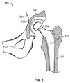
先ず図1を参照すると、健常者の股関節100が示されている。図1から分かるように、股関節100には、骨盤骨104内に寛骨臼と呼ばれる臼窩102があり、これが寛骨臼軟骨106で内張りされている。健常者は、大腿骨110の上端の大腿骨骨頭108が寛骨臼102内に収納されている。
Referring first to FIG. 1, a healthy person's
次に図2を参照すると、THR又はTHA手術後のヒトの股関節200が示されている。THR又はTHAの手術中に、寛骨臼202が拡孔されて(すなわち、図1の寛骨臼軟骨が除去されて)、寛骨臼部品つまりインプラント220が寛骨臼202に取り付けられる。大腿骨210の大腿骨骨頭(例えば、図1の大腿骨骨頭108)も除去される。具体的には、大腿骨210が既知の方法で開孔され、大腿骨部品と称されるボール/ステム部品211が開孔された大腿骨210内部に挿入される。
Referring now to FIG. 2, a human hip joint 200 after THR or THA surgery is shown. During THR or THA surgery, the
THAの重要な側面は、寛骨臼部品すなわちインプラントの骨盤に対する適切な整列を確保することである。具体的に言うと、骨盤に対する寛骨臼部品すなわちインプラントの適切な整列に失敗すると、早期摩耗や脱臼傾向や患者の不快感に至る可能性があることを研究結果が示している。 An important aspect of THA is to ensure proper alignment of the acetabular part or implant to the pelvis. Specifically, research has shown that failure to properly align the acetabular component or implant relative to the pelvis can lead to premature wear, dislocation tendencies and patient discomfort.
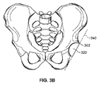
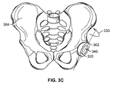
骨盤骨格に対する寛骨臼部品すなわちインプラントの配置方向は、外転角と前傾角によって定義される。図3A、3B、3Cはすべて寛骨臼インプラント320のある骨盤の正面図であり、外転角と前傾角を示している。図3Aでは、外転の方向を矢印330で、外転角は角度332で示されている。一般的に外転は、寛骨臼302内における寛骨臼部品すなわちインプラント320の横方向枢動に関係する。
The orientation of the acetabular component or implant relative to the pelvic skeleton is defined by the abduction angle and anteversion angle. 3A, 3B, and 3C are all front views of the pelvis with the
図3A〜3Cにおいて、前傾方向が矢印333で示されている。図3Bは、前傾角が0度の場合の寛骨臼インプラントを示している。読者側からインプラントの臼窩が見えるような、軸340を中心とする寛骨臼インプラント320の回転は、正の角度の前傾となっている。例えば、図3Cの寛骨臼インプラント320は、正の角度の前傾である。一般的に、前傾は寛骨臼部品すなわちインプラント320の寛骨臼302内での垂直方向(つまり、手術台の上に仰向けに寝ている患者に対する垂直方向)への傾斜に関係する。外転と前傾は、動作的、X線写真的、かつ解剖学的に定義されてもよい。
3A to 3C, the forward tilt direction is indicated by an
研究によると、標準的な健康人の外転は理想的には30〜50°の範囲であり、前傾は理想的には5〜25°の範囲にある。 Studies show that standard healthy person abduction is ideally in the range of 30-50 ° and forward tilt is ideally in the range of 5-25 °.
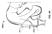
また、人工股関節置換術の成功結果として非常に望まれるのは、脚長とオフセットと大腿骨の回転中心とに所望通りの結果が達成されることである。人体の解剖学的見地から見た脚長とオフセットの定義は文献に記載されており、当業者には周知である。図4A、4Bには、置換術前400a(図4A)と置換術後400b(図4B)の腰と大腿骨が前後方向の図で示されている。元々の脚長405aとオフセット407aは、骨盤401上の標識点(又は参照位置)と大腿骨403上の標識点との間のベクトルの成分である。術後の脚長405bとオフセット407bは、骨盤401と大腿骨403の上の同じ標識点同士の間のベクトルの成分である。術後の脚長405bとオフセット407bは、大腿骨の408bの回転中心(COR)の位置と大腿骨インプラントの寸法とで決まる。元々の脚長405aとオフセット407aは、術前の撮影(例えば、X線、CTスキャン、及びMRI)、並びに元々の大腿骨COR408aを用いて測定されてもよい。所望の結果的な脚長とオフセットと、元々の脚長405aとオフセット407aとから、脚長とオフセットの所望の変化量を算出することができる。
Also, what is highly desired as a successful result of hip replacement is to achieve the desired results for leg length, offset, and center of rotation of the femur. Definitions of leg length and offset from the anatomical point of view of the human body are described in the literature and are well known to those skilled in the art. FIGS. 4A and 4B show the waist and femur in a anteroposterior view of the pre-replacement 400a (FIG. 4A) and post-replacement 400b (FIG. 4B). The original leg length 405 a and the offset 407 a are components of a vector between the marked point (or reference position) on the
手術を確実に成功させて関節プロテーゼの所望の易動度と耐久性を得られるように支援するためには、術後の脚長405bとオフセット407bを、元々の脚長405aとオフセット407aに関して術前に決定した所望値に合致させることが重要であろう。術後の所望の脚長とオフセットは、術中に(センサユニットを利用して)脚長とオフセットをモニタして、脚長とオフセットの所望の変化量を実現することにより達成し得る。また、術前、術後の大腿骨CORの位置を、大腿骨COR位置の前後方向の変化も含めて決定することが望ましい。これはセンサユニットを利用して実現させてもよい。 In order to ensure that the surgery is successful and to obtain the desired mobility and durability of the joint prosthesis, the post-operative leg length 405b and offset 407b are pre-operative with respect to the original leg length 405a and offset 407a. It may be important to meet the determined desired value. The desired post-operative leg length and offset can be achieved by monitoring the leg length and offset during surgery (using a sensor unit) to achieve the desired change in leg length and offset. In addition, it is desirable to determine the position of the femoral COR before and after the operation, including changes in the front-rear direction of the femoral COR position. This may be realized using a sensor unit.
II.システムレベルでの装置の説明 II. Device description at system level
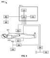
次に図5を参照すると、本発明の実施形態による、体部位と体部位、体部位とプロテーゼ、体部位とツール、及びツールとプロテーゼ、との相対位置関係を事前に測定するためのシステム500が示されている。この例示的なシステム500には、複数のセンサユニット502、503、504、505、506があり、それらが相互に作用しあって、センサが接続された部品同士間の相対位置関係を測定する(ここで、図5に示す接続は有線または無線伝送を表す)。第1のセンサユニット(又は参照センサユニット)502は、患者の骨盤にピン又は骨ネジを固定し、そのピン又は骨ネジに第1の(参照用の)センサユニット502をねじ留めかクリップ留めかまたはその他の取付方法で患者507の骨盤に動作可能に接続されるが、詳細は以下で説明する。第2のセンサユニット503はセンサ位置測定装置508に動作可能に接続される。その他のセンサユニット504、505、506は患者507の大腿骨と、寛骨臼プロテーゼ挿入ツール509と、リーマ(拡孔器)530とにそれぞれ動作可能に接続される。以下で詳細を述べるように、各センサ503、504、505、506は、マーカ又はマーカアレイで置き換えてもよい。
Referring now to FIG. 5, a
寛骨臼プロテーゼ挿入ツール509とリーマ530は、システム500の一部を成し得る手術器具(すなわち剛体)の単なる例であって、人工股関節置換術において普通に利用されるものである。当業者であれば、他の医療用プロテーゼを対応する体部位又は患者の骨に取り付けるために利用される手術器具も本明細書において考慮されることは理解されるであろう。システム500には計算装置511も含まれ、そこにはプロセッサ512、ディスプレイ装置514、及びデータベース516が含まれてもよい。
The acetabular
ディスプレイ装置514は手術手順に関する情報を表示してもよい。通常、表示される情報は、人工股関節置換術中に医師、例えば整形外科医に向けたものである。ディスプレイ装置514はコンピュータ用モニタ、テレビジョン、LCDタッチスクリーン、7セグメントディスプレイ、タブレット、スマートフォン、又はその他の任意の種類のディスプレイであってよい。ディスプレイ装置514は、その時手術室内に統合されている独立型ユニットであってもよいし、又は例えば509、530の手術器具に取り付けられていてもよい。表示される情報としては、これに限るものではないが、体部位や器具やプロテーゼの相対的な位置関係情報であってよい。一実施形態において、ディスプレイ装置514は寛骨臼部品の外転と前傾の角度を示す。別の実施形態においては、ディスプレイ装置514は拡孔の深さと角度に関する情報を表示する。また別の実施形態では、ディスプレイ装置514は脚長とオフセットの変化を表示する。手術に関連するその他の情報が表示されてもよい。例えば、医療画像が入手可能な場合には、手術手順に含まれる様々な手術器具及び骨の実時間運動を追跡する表示(例えば拡張現実表示)と共に表示されてもよい。
The
例示的な実施形態においては、計算装置511が、センサユニット502、503、504、505、506の少なくとも1つ及びディスプレイ装置514とのインタフェースとなっている。計算装置511がセンサのデータを受信し、それを処理して相対的な位置情報を決定する。一実施形態においては、処理には拡張カルマンフィルタ(EKF)又はその一変形(すなわち反復EKF)の利用が含まれる。別の実施形態では、プロセッサ512にレーベンバーグ・マーカート法(Levenberg−Marquardt method)のような非線形反復解法器が含まれている。計算装置511が受信するセンサのデータには、十分な情報が含まれていて所望の相対位置関係データを決定できる(言い換えれば、所望の相対的位置関係データは好ましくは少なくとも局所的に可観測性のあるセンサ情報である。ここで、“局所的可観測”という用語は、制御および推定の分野における通常の意味で使用されている)。計算装置511はデータをフォーマットし、実施形態のあるものではフォーマットされたデータをデータベースに転送して記憶する。相対位置関係を決定することには必ずしも必要ではないが手術手順に関する追加情報(例えば、日付、時間、患者の個人情報)が、データベース516に送信されて記憶されてもよい。データベース516は、手術室内、病院内、中央医療情報保管施設内、又はデータを安全に記憶可能なその他の任意の場所内に配置されてよい。
In the exemplary embodiment,
計算装置511はまた、処理済みデータをディスプレイ514へ送信してもよいし、また例えばキーボードやマウス(図示せず)などのような他の入力装置を備えていてもよい。これらは514上に表示された情報とインタラクトするのに使用されてもよい。さらに、計算装置511は(例えば、X線、CTスキャン、MRIなどの)医療画像データとのインタフェースとなっていてもよい。そうしてこれらのデータをディスプレイ514上に表示してもよい。
The
A.人工股関節整列システムと方法 A. Hip prosthesis alignment system and method
整形外科医の多くは人工股関節置換術時に骨盤にピン又は骨ネジを固定する。図6を参照すると、患者607(破線で示す)の骨盤604の腸骨601にしっかりと固定されたピン又は骨ネジ610の一例が示されている。この例では、ピン又は骨ネジ610は患者607の皮膚又はその他の軟組織を通して挿入され、ねじ留め又は衝撃によって患者の腸骨601に固定されている。ただし、骨盤上の(例えば手術創内の)他の場所においては動作可能な接続610となっていてもよい。以下で更に説明するように、ピン又は骨ネジ610は、センサユニットを取り付けるためのインタフェースとして利用されてもよい。例えば、ピン又は骨ネジ610を利用して、第1の(又は参照又は骨盤の)センサユニット(例えば図5のセンサユニット502)が患者607の骨盤604に取り付けられる。同様のピン又は骨ネジを用いて、別の(又は第2の)センサユニット(例えば図5のセンサ504)を患者607の大腿骨(図示せず)に取り付けられてもよい。センサユニットは、例えば、患者の骨盤から延びるピン又は骨ネジのねじの切られた端部の上にセンサをねじ留めして取り付けられてもよい。または、ピン又は骨ネジの端の上にセンサをクリップ留め又は他の方法で固定してもよい。センサユニットを動作可能に接続する他の手段を利用して(例えば生物学的適合性のある接着剤により)骨にセンサユニットを接続してもよいことは当業者には明らかであろう。
Many orthopedic surgeons fix a pin or bone screw to the pelvis during hip replacement. Referring to FIG. 6, an example of a pin or
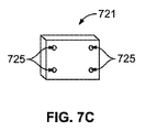
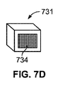
図7A〜7Dには、4つの異なるセンサユニット701、711、721、731が示されている。図7A、7B、7Dには、少なくとも1つの光学センサ(それぞれ704、714、734)が埋め込まれたセンサユニット(それぞれ701、711、731)の例が示されている。
7A-7D, four
光学センサは、受光可能で、光源の方向を判定できる任意のセンサを指す。典型的な光学センサは、CMOSやCCDやそのほかのタイプのカメラであり得る。光学センサの他の例としては、感光装置(PSD)がある。光学センサの他の例は、バアント(Baanto)社(ミシソガ(Mississauga)市、オンタリオ州)から発売されている、Shadow Sense(登録商標)という商品がある。他の光学センサの例は当業者には明らかであろう。一実施形態において、光学センサは赤外(IR)光を受信する。ただし、本明細書において光学センサをIRスペクトル領域の光を検出するものに限るわけではない。 An optical sensor refers to any sensor that can receive light and can determine the direction of a light source. A typical optical sensor can be a CMOS, CCD, or other type of camera. Another example of an optical sensor is a photosensitive device (PSD). Another example of an optical sensor is a product called Shadow Sense®, sold by Baanto (Mississauga, Ontario). Examples of other optical sensors will be apparent to those skilled in the art. In one embodiment, the optical sensor receives infrared (IR) light. However, in this specification, the optical sensor is not limited to one that detects light in the IR spectral region.
図7A〜7Cはセンサユニット701、711、721の例であり、それぞれにマーカ(705、715、725)を持っている。(特に、IR光学センサが利用される)一実施形態においては、マーカはIRマーカである。マーカは必ずしもIR関係のものである必要はなく、対応する光学センサで撮影された像の上で識別可能な特徴として見える任意の物体であってよいことは、当業者であれば分かるであろう。マーカの他の例としては、逆反射マーカ(これは好ましくはマーカに向けられた光エネルギ源を伴っている)及び発光ダイオード(LED)がある。ただしこれに限定するものではない。マーカ705、715、725は、点光源として図示されている。点光源以外の光源も使用可能であり、かつ点光源よりも利点を持つ場合があることは当業者には明らかであろう。
7A to 7C are examples of the
図7Aのセンサユニット701を参照すると、センサユニット701は取付ブラケット702を介して剛体(例えば骨又は手術器具)に連結されていてもよい。例えば、センサユニット701は取付ブラケット702を介して骨ネジ又はピン(例えば図6の610)へ連結されていてもよい。センサユニット701はハウジング703で囲まれている。センサユニット701は、ハウジング703で遮られていない、少なくとも1つの光学センサ704を含んでいる。センサユニット701は2つのマーカ705を含んでいる。センサユニット701は、ハウジング内に追加のセンサ706を含んでいてもよい。追加のセンサ706は、加速度計、ジャイロスコープ、磁力計を含んでいてもよいが、ただしこれに限られるものではない。
Referring to
プロセッサ707がセンサユニット701の内部に埋め込まれていてもよい。埋め込まれたプロセッサ707は、アナログデータをデジタルデータに変換し、そのデータにフィルタを掛けるかその他の調整を行って、通信チャネル709による送信に備えてもよい。通信チャネル709は、有線又は無線であってよく、任意の好適なプロトコル(例えば、RS−232、ブルートゥース(登録商標)、WiFi、USB、SPI、I2C、IR)によって通信されてよい。センサユニット701は電源708によって給電される。電源としては、これに限定されるものではないが、内部電池、又は外部電力線が含まれてよい。電源708として電池が使用される実施形態においては、センサユニット701は再充電端子(図示せず)を備えていてもよい。
The processor 707 may be embedded inside the
センサユニットは一般的に複数のマーカを持っている。例えば、図7Bは例示的なセンサユニット811を示し、ここには4つのマーカ715がある。センサユニット711はそれ以外についてはセンサユニット701と同じである。センサユニット上に3つを超えるマーカが配置される場合、マーカのすべてが同一面上とはならないように配置すると有利になる場合がある(例えば、検出がよりロバストになり得る)。
The sensor unit generally has a plurality of markers. For example, FIG. 7B shows an
図7Cはマーカ725を4つ持っているが光学センサを持っていないセンサユニット721を示す。センサユニット721はそれ以外ではセンサユニット701、711と同じである。既に述べたように、3つを超えるマーカを利用する場合、すべてのマーカが必ずしも同一面ではないことが有利となることがある。
FIG. 7C shows a
図7Dは光学センサを持っているがマーカのないセンサユニット731を示す。それ以外においては、センサユニット731はセンサユニット701、711、721と同じである。
FIG. 7D shows a
一般的に2つのセンサユニット間の6自由度の相対位置関係を測定するためには、2つのセンサユニット間に、少なくとも1つの光学センサと少なくとも3つのマーカが必要である。光学センサとマーカの最小限の組合せより多い組合せを有することが好ましい。6自由度よりも少ない相対位置関係を計測するためには必要とするマーカは少なくてもよい。 Generally, in order to measure the relative positional relationship of 6 degrees of freedom between two sensor units, at least one optical sensor and at least three markers are required between the two sensor units. It is preferred to have more than the minimum combination of optical sensors and markers. In order to measure a relative positional relationship with less than 6 degrees of freedom, fewer markers may be required.
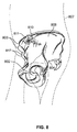
次に図8を参照すると、患者807(破線で示す)の骨盤804が図示されている。患者の骨盤804にピン又は骨ネジ810が取り付けられ、そこにセンサユニット811が取り付けられて第1の(又は参照又は骨盤の)センサユニットとして機能する。センサユニット711(図7)が例示の目的で第1の(又は参照又は骨盤の)センサユニット811として選択されている。
Referring now to FIG. 8, the
第1の(又は参照又は骨盤の)センサユニット811の目的は、(骨盤の参照枠内で)センサ測定値を計算装置(例えば図5の511)に提供し、他のシステム部品(例えば骨盤骨、大腿骨、手術器具、プロテーゼなど)との間の相対的位置関係を最終的に決定することである。参照の骨盤フレームは、登録などのような方法によってセンサユニット811に関連付けられる。一実施形態において、登録は、患者の骨盤上に複数の標識点又は参照位置(例えば上前腸骨棘(ASIS)803と、下前腸骨棘(AIIS)817と、腸骨稜806に沿ったポイントなど)を第1の(又は参照又は骨盤の)センサ811に対して配置することにより遂行される。
The purpose of the first (or reference or pelvic)
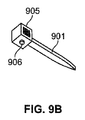
図9A、9Bでは、一実施形態において、第1の(又は参照又は骨盤の)センサユニット(例えば図8の811)に対する、患者の骨盤上の標識点(又は参照点)を配置するために(センサと共に)使用され得る、針901が記述されている。針901は近位端902と遠位端903を有する剛体から成る。遠位端903は、体部位及び/又は他の特徴点又は標識点(又は参照点)への接触のための、輪郭の明瞭な接触点を持ち、近位端902はセンサユニット905を収納できるようになっている。センサユニット905は図7のセンサユニット701、711、721、又は731のうちの1つであってよく、また、ボタン906のようなヒトとのインタフェースセンサを少なくとも1つ追加的に備えていてもよい。ボタン906はセンサユニット905内のプロセッサ(図示せず)とのインタフェースとなっていてもよい。一実施形態において、針901は、第1の(又は参照又は骨盤の)センサユニット811(図8)に対する、骨盤上の標識点又は参照位置(例えば図8の803、817、806)の位置を決定するために使用される。ボタン906を押すと、計算装置(例えば図5の511)、及び/又は第1の(又は参照又は骨盤の)センサ(例えば図8の811)に、針が標識点又は参照位置に接触したこと、従ってセンサユニット905が標識点又は参照位置に対して既定の位置にあることを送信する。ボタン906を押すことで、センサユニット905の相対的位置が登録/保存されてもよい。
9A and 9B, in one embodiment, to place a landmark (or reference point) on the patient's pelvis relative to a first (or reference or pelvic) sensor unit (eg, 811 in FIG. 8) ( A
図10には、一実施形態により、センサユニット1005が取り付けられた寛骨臼カップ挿入ツール1000が示されている。センサユニット1005はツール1000に固定されている。一実施形態においては、センサユニット1005はセンサ905(図9)と同じセンサである。一実施形態において、センサユニット1005はセンサ905と同じセンサであって、針901(図9)に取り付けられており、針901は寛骨臼カップ挿入ツール1000に直接取り付けられている。この実施形態においては、針901は針901の自由端903が連結部1013内に例えば固定ネジ(図示せず)を用いて固定されることによってツール1000に固定されていてもよい。別の実施形態において、ツール1000に一体的に形成されていてもよい連結部1013にはネジ溝が切られていて、連結部(例えばピン)1001の一端にある相補的なネジ溝と噛み合うようになっていてもよい。この連結部(例えばピン)1001のもう一端には、センサユニット1005の相補的なねじ溝と噛み合うねじ溝があってもよい。ネジ溝を利用する代わりに、センサユニット1005を連結部1001に、また連結部1001をツール1000の連結部1013に連結するために、例えば機械的な留め具を用いてもよい。センサユニット1005は、図7に示したセンサユニット701、711、721、731の内の任意の1つであってよい。更に、センサ1005は、一実施形態においては針901である連結部1001を介して、挿入ツール1000に連結されてもよい。挿入ツール1000の端部には寛骨臼プロテ−ゼ・インプラント(すなわち寛骨臼カップ)1015が保持される。センサユニット1005はツール1000に既知あるいは測定可能な向きで接続され、挿入ツール1000に対するセンサユニット1005の相対位置が、2つの要素を接続すると分かるようになっている。例えば、挿入ツールと連結部とセンサが既知の寸法仕様で製造されていて、かつ3つの部品が1つの特定の仕方でしか組み立てられないようになっている場合、3つの部品は計算された相対位置関係に従って予測可能なやり方で組み立てることができる。使用される1つまたは複数の部品の寸法が調整可能な場合(例えば、次に述べる骨盤登録装置)、部品間の相対位置は、部品同士の距離と角度方向を計測することで決定され得る。
FIG. 10 illustrates an acetabular
図11を参照して記述される別の実施形態において、骨盤登録装置1100は骨盤上の3つの標識点(又は参照点)に接触するように用いられてもよい。一実施形態において、第1と第2の接触部材1117、1106が、接触部材1117と1106上のそれぞれの第1の接触点1107と第2の接触点1109において、それぞれのASISポイント1103に接触するように用いられ、そして第3の接触部材1110を用いて腸骨稜1105上の触診可能な位置が第3の接触部材1110上の第3の接触点1111において接触される。他の骨盤標識点(参照位置)(例えば下前腸骨棘、恥骨結節、寛骨臼縁、円索の連結点、など)が使用されてもよく、それは当業者には明らかであろう。装置の例がPCT出願公開WO/2010/063117号に開示されており、参照によりその全体を本明細書に援用する。第1と第2の接触部材1117、1106は、第1と第2の調節可能な支持棒1114、1116に取り付けられており、それらは交叉部材1124に固定されている。剛体部材(すなわちシャフト)1102は、その長手軸を中心に自由に回転できるか、または回転しないように固定されて支持棒1114を越えて延びていてもよい(支持棒1114の先に延びている剛体部材又はシャフトの部分は1122で表示されている)。第3の接触部材1110は第3の支持棒1108に取り付けられており、これは剛体部材(すなわちシャフト)1102の延長部分1114に、ジョイント1118を介して連結されている。第3の支持棒1108は好ましくは剛体部材(すなわちシャフト)1102に動作可能に連結され、剛体部材(すなわちシャフト)1102が長手軸を中心に回転すると第3の支持棒1108もその軸を中心に同様の回転をするようになっている。非限定的な実施例として、第3の支持棒は、剛体部材(すなわちシャフト)1102(または、支持棒1114を越えた剛体部材すなわちシャフトの延長部分1122)と一体的に形成又は溶接されていてもよい。
In another embodiment described with reference to FIG. 11, the
第3の接触部材1110は、腸骨稜1105沿いの触診可能点に接触するのに好適な形状となっている。連結部1131は、第3の支持棒1108に結合され、第2のセンサユニット1130は連結部1131に結合されている。非限定的な実施例として、連結部1131は両端にねじが切られたピンであって、第3の支持棒1108と第2のセンサ1105にある相補的なねじ溝と噛み合うようになっている。この連結部1131は第3の支持棒1114に結合されるのが好ましいが、この連結部1131(及び連結部1131に結合された第2のセンサ1130)が結合されている登録装置の別の部品が、第3の支持棒1108に動作可能に結合されている(つまり、第3の支持棒1108が回転軸の周りを回転すると、別部品が同一回転軸の周りを同様に回転させられる)場合には、この連結部は代わりに登録装置1100の別部品に接続されていてもよいことは、当業者は理解するであろう。また、第2のセンサユニット1130が、連結部1131を介して骨盤整列1100の部品に結合されている場合、第1、第2、第3の接触点1107、1109、1111に対する第2のセンサユニット1130の相対位置が分かっていることが望ましい(つまり、第2のセンサユニット1130が骨盤登録装置1100に連結されている場合に、第2のセンサユニットは第1、第2、第3の接触点1107、1109、1111のそれぞれに対して既定の関係を有している)。
The
そのように、骨盤登録装置1100のすべての機械的寸法は、固定されて既知であるか、調整可能かつ測定可能であるかのいずれかである。更に、骨盤登録装置1100上のどこにあってもよいが、少なくとも1つのヒューマンインタフェース・センサ(例えばボタン1132)がセンサユニット1130へのインタフェースとなっていて、装置1100が患者の骨盤に対して定位置にあることを計算装置(例えば図5の511)に通信できるようになっていてもよい。実施形態において、ボタン1132は、それぞれ第1、第2、第3の接触点107、1109、1111における3つの圧力センサを備え、各ポイントにおける特定の圧力が、骨盤登録装置1100が骨盤に対して所望の位置にあることを計算装置に知らせるようになっている。
As such, all mechanical dimensions of the
骨盤登録装置1100は、図9Aと図9Bで説明した針の実施形態の代わりに、第1の(又は参照又は骨盤)のセンサユニット811に対する、骨盤上の標識点又は参照位置(例えば図8の803、817、806)の位置関係の決定に使用されてもよい。図9の第2のセンサユニット905と同様に、第2のセンサ1130は、図7に示されたセンサユニット701、711、721、731の1つであってよい。
The
図12は、図9に示した針/センサユニットの組合せを利用した、患者1207(破線で示す)の骨盤1204に対する第1の(又は参照又は骨盤の)センサユニット1211の相対位置を決定する方法を示している。患者1207の骨盤1204に動作可能に結合された第1の(又は参照又は骨盤の)センサユニット1211(例えば上述したような)があれば、(図12に示すように)針1201の遠位端1202を利用して、針1201が恥骨結節1208(骨盤1204上の骨の1つの標識点)に接触させられる。針1201が(骨に直接でも、皮膚や他の軟組織を介してでも)適切に骨の標識点に係合されると、ボタン1212を押して針1201が係合されたことを合図してよく、これにより、第2のセンサユニット1205から計算装置(例えば図5の511)又は第1の(又は参照又は骨盤の)センサユニット1211への通信伝送が開始される。一実施形態において、第1の(又は参照又は骨盤の)センサユニット1211と第2のセンサユニット1205が選択されて、一方のセンサが少なくとも1つのカメラを備え、もう一方のセンサが、通信伝送時に少なくともそのカメラの1視野内に存在する対応するマーカを備えるようにして配置される。通信伝送時に、センサユニット1211と1205で得られる統合情報で、センサユニット1211と1205間の6自由度の相対的位置関係を十分に決定できる。従って、通信伝送時に、針1201と接触している骨の標識点に対して第1の(又は参照又は骨盤の)センサユニット1211の6自由度の位置を相対的に決定することができる。
FIG. 12 illustrates a method for determining the relative position of the first (or reference or pelvic)
一実施形態において、大腿骨を登録することが(しばしば脚長/オフセットの決定に利用するために)望ましい場合がある。そのような実施形態においては、針1201を利用して大腿骨に沿う標識点に接触することが可能である。
In one embodiment, it may be desirable to register the femur (often for use in determining leg length / offset). In such an embodiment, the
相対的な位置関係を決定するためには、センサユニット1211と1205の特定の組合せでは不十分であることを当業者は理解するであろう。例えば、図7のセンサユニット721(マーカのみを備え、カメラがない)がセンサユニット1211として使用された場合、このセンサユニット721をセンサユニット1205としては使用できないし、その逆も同様である。センサユニット731(カメラのみを備え、マーカがない)がセンサユニット1211あるいは1205のいずれかとして使用された場合、もう一方のセンサユニットは711か721のタイプ(すなわち好ましくは少なくとも3つのマーカを備えるもの)であることが望ましい。相対的位置関係を決定するための十分な統合情報を提供できないセンサユニットの種類の組合せが多くあり、これらは対応する測定のできないセンサを含んでいることもある(すなわち一方のセンサにカメラがあるが、相手のセンサにマーカがない、というような)。どのセンサユニットの組合せが適切(すなわち、所望の相対的位置関係が局所的可観測)であるかは、当業者には明らかであろう。
One skilled in the art will appreciate that the specific combination of
患者の骨盤1204に対する第1の(又は参照又は骨盤の)センサユニット1211の相対位置を決定するために、骨盤上の少なくとも3つの別々の既知の標識点(又は参照点)の位置が特定されて計算装置(例えば図5の511)内に記憶される。骨の標識点(又は参照点)になり得るものの例としては、恥骨結節1208、ASISポイント1203、AIISポイント1217、腸骨稜1206に沿うポイント、又は円索の連結点などのような寛骨臼1216に関連する骨の標識点(又は参照点)、などがある。
To determine the relative position of the first (or reference or pelvic)
次に図11と図12を参照する。別の実施形態において既に述べたように、図11の骨盤登録装置1100は患者1207(図12に破線で示す)の骨盤1204に対する第1の(又は参照又は骨盤の)のセンサユニット1211の相対的位置を決定するために使用されてもよい。第1の(又は参照又は骨盤の)センサユニット1211が患者1207の骨盤1204に(例えば上記のように)動作可能に結合された状態で、骨盤登録装置1100が骨盤上の少なくとも3つの既知の標識点(又は参照点)に接触させられる。第2のセンサユニット1130が、第1、第2、第3の接触点1107、1109、1111のそれぞれに対して既定の関係があるか、それぞれに対して測定可能であることにより、骨盤登録装置1100が少なくとも3つの標識点(又は参照点)と接触している場合には、第2のセンサ1130に対する第1の(又は参照又は骨盤の)センサユニット1211の相対位置を利用して、第1の(又は参照又は骨盤の)センサユニット1211に対する骨盤骨1204の相対的位置を決定することができる。
Reference is now made to FIGS. As already mentioned in another embodiment, the
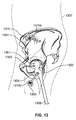
図4A,4Bに関して既に述べたように、人工股関節置換術においては、手術前後での脚長とオフセットに所望の変化を得ることが極めて望ましい。次に人工股関節置換術を通してどのようにして所望の脚長とオフセット(例えば405bと407b)を得るかを示す図13を参照する。患者の骨盤1304と大腿骨1306が示されている。ここでは大腿骨骨頭1301と寛骨臼1302の領域が手術創内に露出されている。骨盤1304に対する大腿骨1306の位置を測定するために、大腿骨センサユニット1305が大腿骨1306に連結されている(これは例えば、両端にねじの切られたピンを用いて、一端を大腿骨の中にねじ留めし、もう一端を大腿骨センサユニット1305の相補的なねじに噛み合せるか、あるいはピンを大腿骨中に打ち込んでセンサをピン上に機械的にクリップすることによって行う。ただしこれに限定されるものではない)。一実施形態において、センサユニット1305はピン又は骨ネジ1310bを用いて大腿骨1306の大転子1309付近に連結される。別の実施形態においては、センサユニット1305は、機械的または解剖学的な大腿骨軸に沿うように配置される(例えば、大腿遠位付近に経皮的に連結されてもよい)。
As already described with reference to FIGS. 4A and 4B, in hip replacement surgery, it is highly desirable to obtain desired changes in leg length and offset before and after surgery. Reference is now made to FIG. 13 showing how the desired leg length and offset (eg, 405b and 407b) are obtained through hip replacement. A patient's
手術前後の脚長とオフセットの変化を測定する方法はいくつかある。股関節ナビゲーション技術においては、大腿骨骨頭の回転中心(骨頭中心と称する)の位置決定を基にする方法がある。そのような方法では大腿骨を関節接合し、あるいは大腿骨骨頭及び/又は寛骨臼を登録することが含まれる。ある方法では、距離測定結果を脚長とオフセットを表す成分に分解する方法を取る。そのような方法では、大腿骨登録を行って、機械的、及び/又は解剖学的な大腿骨軸を決定することが含まれる。 There are several ways to measure changes in leg length and offset before and after surgery. In the hip joint navigation technique, there is a method based on the position determination of the rotation center of the femoral head (referred to as the head center). Such methods include articulating the femur or registering the femoral head and / or acetabulum. In one method, the distance measurement result is decomposed into components representing leg length and offset. Such methods include performing a femoral registration to determine a mechanical and / or anatomical femoral axis.
大腿骨センサユニット1305と第1の(又は参照又は骨盤の)センサユニット1311とで測定された情報は、計算装置(例えば図5の511)へ送信され、センサユニット同士の相対的位置関係、従って大腿骨1306と骨盤1304との相対的位置を決定するための十分な情報を含んでいる。この情報は、可能であれば大腿骨骨頭中心、及び/又は大腿骨軸に関する情報と併せて、手術の前と後の両方で測定されてもよい。手術(すなわち、プロテーゼ部品による股関節整復)後の測定情報を手術前の測定情報と比較することで、手術結果としての実際の脚長とオフセットの変化が得られる。同様に、大腿骨位置の前後方向の変化も判定され得る。脚長とオフセットの実際の変化量が、既定の所望の脚長とオフセットに合致していれば、所望の最終的な脚長とオフセットが実現されていると言える。大腿骨センサユニット1305に対するセンサユニットの選択肢は、(図9の)針センサユニット905として選択可能なものとして前述したものと同じ選択肢である。
Information measured by the
図14を見ると、寛骨臼インプラント(すなわち図10の1015)を挿入する前に、寛骨臼1402が拡孔され、これは必然的に骨、軟骨及び組織の除去を伴う。寛骨臼の拡孔は、例えば拡孔ツール1401を用いて実行されてもよい。拡孔センサユニット1405が拡孔ツール1401に連結され、第1の(又は参照又は骨盤の)センサユニット1411と拡孔センサ1405との組合せで十分な情報が測定され、骨盤1404に対する拡孔ツール1401の相対位置を決定できるようなっていてよい(このためには、所与の第1の(又は参照又は骨盤の)センサユニット1411に対して、拡孔センサユニット1405が大腿骨センサ1305と同じようにして選択されなければならない)。骨盤骨1401に対する拡孔ツール1401の相対位置を測定する例示的目的の1つは、拡孔処理の深さや角度を決定することである。一方が拡孔ツール1401上の相補的なねじに連結され、別の一方が拡孔センサユニット1405の相補的なねじに噛み合わされた、両端にねじの切られたピンを用いて拡孔センサユニット1405が連結されてもよい。あるいは、ピンが拡孔センサユニット1405またはマーカアレイ(例えば、図23拡孔ツール2301を参照)と一体的に形成されていて、拡孔ツール1401のねじに合うねじを持っていてもよい。別の代替物としては、拡孔センサユニット1405のねじに合うねじを持った、拡孔ツールと一体となったピンとなっていてもよい。ねじの代わりに機械的なクリップを利用してもよい。
Referring to FIG. 14, prior to insertion of the acetabular implant (ie, 1015 of FIG. 10), the
人工股関節置換術におけるもう1つの重要な因子は、骨盤(特に外転角(例えば図3Aの332)と前傾角(例えば図3Cの333))に対する寛骨臼インプラント(例えば図10の1015)の整列である。図15において、寛骨臼1502が適切に拡孔されると、寛骨臼インプラント1515が挿入ツール1510を用いて寛骨臼1502に挿入され、手術用ハンマ(図示せず)を用いて寛骨臼(1502)の中に打ち込まれる。寛骨臼1502に挿入されるまでは、寛骨臼インプラント1515は挿入ツール1510の既知の位置に連結されている(ツール1510の位置が既知ということは、寛骨臼インプラント1515の位置が既知ということを示している)。図10のツール挿入ツール1000と同様に、ツールセンサユニット1505は挿入ツール1510の既知の位置に連結されている。計算装置(例えば図5の511)と通信するセンサユニット1511と1505からの情報を利用して、骨盤1504に対する管腔臼インプラント1515の相対位置が決定されてもよい。具体的には、寛骨臼インプラント1515の骨盤1504に対する相対的な方向(すなわち、外転角と前傾角)が決定され得る。骨盤に対する寛骨臼インプラント1515の所望の方向を実現すれば、外科医はインプラント1515を寛骨臼1502の中に固定してよい。
Another important factor in hip replacement is the acetabular implant (eg 1015 in FIG. 10) for the pelvis (especially the abduction angle (eg 332 in FIG. 3A) and anteversion angle (eg 333 in FIG. 3C)). Alignment. In FIG. 15, when the
複数のセンサを用いた、脚長とオフセットの変化の測定は、図13を参照して既に議論した。繰り返して言うと、手術中に脚長又はオフセットのいかなる変化をも測定することは重要である。図16は、複数のセンサユニットを利用して最終的に所望の脚長とオフセットを実現する方法を示している。寛骨臼プロテ−ゼ1615と大腿骨プロテーゼ1608(図2の208も参照)とをインプラントした後、人工関節が組み立てられる、つまり(典型的には先ず寸法変化を許容する試行部品を用いて)整復される。結果的に得られる位置には、実際の最終的な脚長(例えば図4Bの405b)と実際の最終的なオフセット(例えば図4Bの407b)が含まれる。骨盤に対する大腿骨上の1点の位置の初期参照測定と、人工関節を組上げた後の同一点の位置との間の変化を計算することが可能である。このことは、手術の前と後とで記録された(骨盤1604内の)センサ1611と(大腿骨内の)センサ1605とから集められた情報から、脚長とオフセットの変化が決定される、ということを意味している。脚長とオフセットを正確に決定するために、大腿骨骨頭の中心位置を計算すること、あるいは、大腿骨位置同定手順(これは骨頭中心位置の決定も含む)を利用して、初期測定と整復後の測定値の比較をできるようにすること(例えば、初期の大腿骨の向きを復元させるように医師を導くこと)も有利である。
The measurement of leg length and offset changes using multiple sensors has already been discussed with reference to FIG. Again, it is important to measure any change in leg length or offset during surgery. FIG. 16 shows a method of finally realizing a desired leg length and offset using a plurality of sensor units. After implanting the
B.立体的な1つのアクティブセンサユニットの実施形態 B. Embodiment of one-dimensional active sensor unit
前節においては、ツールと体部位、体部位と他の体部位、及び体部位とプロテーゼとの相対的位置関係を測定する装置について、とりわけ人工股関節置換術におけるプロテーゼ部品の整列と寸法調整の関連において開示した。本節においては、同様の機能を有する装置の一実施形態を開示する。 In the previous section, we will discuss tools and body parts, body parts and other body parts, and devices for measuring the relative positional relationship between body parts and prostheses, especially in relation to alignment and sizing of prosthetic components in hip replacements. Disclosed. In this section, an embodiment of an apparatus having similar functions is disclosed.
この実施形態においては1つのセンサユニットのみが光学センサを有する。図7Eには、ハウジング743と、ハウジング743に妨げられずに既知の距離だけ離間した2つの光学センサ742aと742bとを有するセンサユニット741が示されている。このセンサユニット741は、ハウジング743内に加速度計やジャイロスコープなどの他の種類のセンサ(図示せず)を含んでいてもよい。更に、センサユニット741には、内部プロセッサとのインタフェースとなる、ヒューマンインタフェース・センサ(例えばボタン)746(複数のヒューマンインタフェース・センサも考えられる)が含まれてよい。このセンサユニット741は、手術器具上の相補的な取付ブラケットに(例えばスナップフィットかねじ留めで)合体するように適合された取付ブラケット744を介して、例えば骨盤に取り付けられてもよい。図7Fには、3つの異なるマーカ構成751a、751b、751cが示されている。それぞれの構成は、それぞれのマーカ753a、753b、753cを結合する剛体752a、752b、752cを持つセンサユニットである。マーカは電磁エネルギ(例えば可視光、赤外光)を放出又は反射してもよい。一実施形態において、マーカが放出又は反射するエネルギの種類は、使用されるセンサユニット741の種類に対応する。マーカを含むが、処理または検出能力を持たないセンサユニットは、代わりに“アレイ”と呼ばれる。任意の数のマーカ753が一つの“アレイ”751を構成してもよい。これはそのアプリケーションが決定に必要とする位置の自由度に依存する(例えば、6自由度の全てを決定するためには、アレイごとに少なくとも3つのマーカを必要とする)。
In this embodiment, only one sensor unit has an optical sensor. FIG. 7E shows a
図17を参照して、患者1707の骨盤骨1704に取り付けられたピン又は骨ネジ1710に取り付けられたセンサユニット1711について議論する。実際には、センサユニットは好ましくは骨に結合されて、センサユニット1711の視野が手術創の全体領域をカバーするようになっている。
With reference to FIG. 17, a
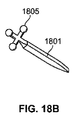
図18Aは、図9Aの針901と類似の針1801を示している。図18Bは、図18Aの針に、マークアレイ1805が結合されたものである。本例示的実施形態においては6自由度の位置決めが必要なので、アレイ1805には3つのマーカがある(ただしそれより多くてもよい)。
FIG. 18A shows a
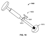
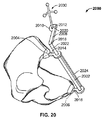
図19には、図10の寛骨臼カップ挿入ツール1000と類似の寛骨臼カップ挿入ツール1900を示す。挿入ツール1900は、前述した連結手法と同じようにして連結部1913を介して連結されたマーカアレイ1905を備えている。アレイ1905は好ましくは、少なくとも2つのマーカポイントを備えている(寛骨臼カップ(すなわちインプラント)の適切な位置決めが、2つの方向角、すなわち外転角332(図3A)と前傾角333(図3C)にしか依存しないので、2つのポイントしか必要でない)。
FIG. 19 shows an acetabular
図20には、骨盤登録装置2000の一実施形態が示されている。この装置は図11の骨盤登録装置1100と同一であり、唯一の違いはセンサユニット1130の代わりに、好ましくは少なくとも3つのマーカから成る1つのマーカアレイ2030を使用していることである。一実施形態においては、装置2000は装置1100(図11)と同じ目的で使用される。装置2000を使用する場合には、装置2000上ではなく、第1の(又は参照又は骨盤の)センサユニット(例えば図17の1711)上にヒューマンインタフェース・センサ(例えばボタン)を有し、装置2000には通信チャネルを持たないようにすることが好ましいこともある。
FIG. 20 shows an embodiment of a
図21では、骨盤上の骨の標識点(又は参照点)の位置が第1の(又は参照又は骨盤の)センサユニット2111に対して決定できるようになったシステムが示されている。針2101とアレイ2105は、骨盤上の様々な標識点(又は参照点)(例えばASISポイント2103とAIISポイント2117))に接触するように用いられてもよい。骨の標識点(又は参照点)に接触している場合、センサユニット2111上のボタン(図示せず)を押して、針2101が標識点(又は参照点)に接触していることを示してもよい。一実施形態において、少なくとも3つの標識点(又は参照点)に接触させて、その位置をセンサユニット2111によるアレイ2105の位置測定から決定する。別の実施形態においては、大腿骨の登録が必要な場合に大腿骨に沿った標識点が記録される。
In FIG. 21, a system is shown in which the location of a bone marking point (or reference point) on the pelvis can be determined relative to a first (or reference or pelvic)
別の実施形態において、図20の骨盤登録装置2000を利用して、少なくとも3つの標識点(又は参照点)に同時に接触することにより、骨盤上の骨の標識点(又は参照点)を、第1の(又は参照又は骨盤の)センサユニット2111に対して決定してもよい。
In another embodiment, using the
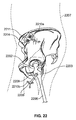
前に議論したように、手術前の脚長(例えば図4Aの405a)とオフセット(例えば図4Aの407a)から、プロテーゼがインプラントされた後の、脚長(例えば図4Bの405b)とオフセット(例えば図4Bの407b)への変化を測定することは重要である。図22を参照すると、この実施形態において、参照とする手術前の脚長(例えば405a)とオフセット(例えば407a)は、(前述したような)ピン又は骨ネジ2210bを用いてアレイ2205を大腿骨2206に動作可能に連結することにより測定してもよい。第1の(又は参照又は骨盤の)センサユニット2211を利用して、アレイ2205上のマーカをトレースすることにより骨盤2204に対する大腿骨2206の手術前の参照位置を決定してもよい。
As discussed previously, the leg length (eg, 405b in FIG. 4B) and offset (eg, FIG. 4B) and offset (eg, FIG. 4A) after the prosthesis is implanted from the pre-operative leg length (eg, 405a in FIG. 4A) and offset (eg, 407a in FIG. 4A). It is important to measure the change of 4B to 407b). Referring to FIG. 22, in this embodiment, the pre-surgical leg length (eg, 405a) and offset (eg, 407a) to be referenced are compared to the
本実施形態による寛骨臼の拡孔を次に図23を参照して説明する。拡孔は、プロテーゼのインプランテーションのための寛骨臼の準備の段階で行われる。ツール2301の例が示されており、好ましくは少なくとも3つのマーカを持つアレイ2305の例がそこに連結されている。そうして第1の(又は参照又は骨盤の)センサユニット2311が、アレイ2305の各マーカの位置を特定することによって拡孔ツールの位置を測定することが可能となる。アレイ2305は、例えば前述した連結方法によって、ツール2301に連結されていてもよい。
Next, the expansion of the acetabulum according to this embodiment will be described with reference to FIG. The dilation is performed during the preparation of the acetabulum for prosthesis implantation. An example of a
本明細書において既に説明した、人工股関節置換術におけるもう一つの重要な考慮すべき点は、骨盤に対する寛骨臼インプラントの向きである。図24を用いて、第1の(又は参照又は骨盤の)センサユニット2411に対する寛骨臼インプラント2415の相対的な向きを決定するための例示的システムを説明する。第1の(又は参照又は骨盤の)センサユニット2411はアレイ2405を光学的に追跡して十分な情報を測定し、アレイ2405の相対位置を決定することが可能である。アレイ2405は既知の(すなわち既定の)相対位置(例えば、前述したような)で挿入ツールに2410連結され、挿入ツール2410は、既知の相対位置で寛骨臼インプラント2415に連結されている。寛骨臼カップは、例えば合体用ネジ溝を介して対応する手術用挿入ツールに連結されてもよい。その結果、(例えば手術前の骨盤のスキャンで測定された)骨盤2404の既定の幾何配置に対して既知の関係で骨盤に(例えば前述したように)連結された、第1の(又は参照又は骨盤の)センサユニット2411により、計算装置(図24には表示せず)が骨盤の幾何配置に対する寛骨臼インプラント2415の位置を決定することが可能となる。
Another important consideration in hip replacement as already described herein is the orientation of the acetabular implant relative to the pelvis. 24, an exemplary system for determining the relative orientation of the
次に図25では、人工関節を組上げた後(一般的には、恒久的な部品を移植する前に適切な寸法を決定するために試行部品を用いて組上げた後)、脚長(例えば図4Bの405b)とオフセット(例えば図4Bの407b)をこの実施形態で測定する方法を示す。第1の(又は参照又は骨盤の)センサユニット2511を用いて、マーカアレイ2505の相対位置を測定してもよい(マーカアレイ2505は図22のマーカアレイ2205と一般的には同一である)。マーカアレイ2505(手術後)の相対位置を、マーカアレイ2205(手術前)の相対位置と比較して、人工関節(2508と2515の組合せ)が組上げられた後の脚長とオフセットの変化を算出することができる。
Next, in FIG. 25, after assembling the prosthesis (typically after assembling with a trial part to determine the appropriate dimensions before implanting the permanent part), the leg length (eg, FIG. 4B). 405b) and offset (eg, 407b in FIG. 4B) are measured in this embodiment. A first (or reference or pelvic)
III.使用方法 III. how to use
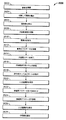
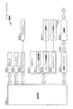
次に、人工股関節置換術の方法の一例が概略的に示された図6を参照する。また、本明細書に記述の方法とシステムの背景を与える図1、2も参照する。ブロック2602において、患者の手術準備(すなわち、清浄、鎮静、体位取り、など)を行う。手術手順はブロック2604の切開で始まる。これは最終的に股関節100を(異なる数層の組織を通して)露出させる。ブロック2606で、患者の股関節を脱臼させ、大腿骨骨頭108を寛骨臼102の外に出す。人工股関節全置換術においては、ブロック2608で示唆するように、大腿骨骨頭108が除去(すなわち切除)される(大腿骨骨頭108はブロック2606で脱臼させる前に切除されてもよい)。典型的には、次の手術手順において寛骨臼102の拡孔を行い(ブロック2610)、寛骨臼102に寛骨臼インプラント220を挿入できるように準備する。寛骨臼が拡孔されると、寛骨臼インプラント・プロテーゼ220がブロック2612に従って移植されてよい。大腿骨もまた拡孔を必要とし(ブロック2614)、大腿骨プロテーゼ部品(大腿骨ボールとステムから成る)211が大腿骨210内に収納できるようにする。大腿骨拡孔は、大腿骨ブローチを用いて行われてもよい。大腿骨210の拡孔が終わると、試行用の大腿骨プロテーゼが、ブロック2616に従って大腿骨内に移植されてもよい。ブロック2618において、試行用のネックとボール部品を用いて、試行用の大腿骨インプラントが組み立てられる。ブロック2620で、人工関節(208と211の組合せ)が組み立てられ、患者の関節の運動範囲がテストされてもよい。試行部品がよく合わない場合には、(寸法の異なる)別のネックとボールを取り付けて、テストを行い、所望の嵌合が達成されるまで繰り返す。所望の嵌合が達成されると、次に、ブロック2622に従って、移植用の実際のプロテーゼ(試行用のものではなく)の寸法が合わせられる。ブロック2624において、試行用の大腿骨部品を実際のプロテーゼと交換して移植する。ブロック2626において、人工関節が組み立てられ関節の嵌合がもう一度検証される。最終的にブロック2628で、手術創が縫合される。
Reference is now made to FIG. 6, which schematically shows an example of a method for hip replacement. Reference is also made to FIGS. 1 and 2 which provide the background of the methods and systems described herein. At
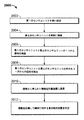
次に図27を参照する。ここでは人工股関節置換術おける本開示システムの利用の概略を示す方法2700を説明している。図27の方法2700は、一般的には図26の方法2600と同時に遂行される。従って図26を継続して参照する。ブロック2702はブロック2710に先立つ任意の時間に遂行されてよいが、一般的には手術の準備時に行われる。手術を受ける患者の骨盤の既定の幾何配置が計算装置に入力される。患者の骨盤の幾何配置はそれぞれに固有であるので、このステップは、骨盤の標識点(又は参照点)が、計算装置(例えば図5の511)によって実際の骨盤の幾何配置に関連付けられる。任意の好適な医療画像手順により得られる患者の骨盤の幾何配置が入手できない場合には、既定の骨盤テンプレートを利用してもよい。患者の準備が整うと(例えばブロック2602)、第1の(又は参照又は骨盤の)センサユニット(例えば図12の1211)が動作可能に骨盤(例えば図12の1204)に結合される。これは例えばブロック2704と2706において、骨盤(例えば1204)に取り付けられて固定されたピン又は骨ネジ(例えば1210)に第1の(又は参照又は骨盤の)センサ(例えば1211)を結合することで実現されてもよい。
Reference is now made to FIG. Described here is a
ブロック2602(患者準備)の後でかつブロック2606(股関節脱臼)の前のブロック2708では、針と第2のセンサユニットの組合せ(すなわち図12の1201と1205、あるいは図21の2101と2105)かまたは骨盤登録装置(例えば1100又は2000)を用いて、少なくとも3つの骨盤標識点(又は参照点)に接触が行われ、第1の(又は参照又は骨盤の)センサユニット(例えば1211)に対する標識点(又は参照点)の位置を測定する。ブロック2710では、標識点(又は参照点)の位置は計算装置(例えば図5の511)により手術前の画像データ又はステップ2702の既定の幾何配置テンプレートに対する関連付けが行われ、骨盤(例えば1204)に対する骨盤センサユニット(例えば1211)の相対位置が決定されるようにする。
In
ブロック2712と2714において、センサユニット又はマーカアレイ(例えば図16の1605または図22の2205)が、例えば前述したようにして患者の大腿骨(例えば1606)に動作可能に結合される。動作可能な結合は、大腿骨(例えば1606)にピン又は骨ネジ(例えば1610b)を介して行われてもよい。ブロック2716において、第1の(又は参照又は骨盤の)センサユニット(例えば図16の1611または図22の2211)と恐らくは大腿骨センサユニット又はマーカアレイ(例えば1605または2205)が計算装置(例えば図5の511)と通信し、まだ関節に処置がされていない状況で大腿骨の元の相対位置が決定されて記憶される。人工股関節置換術のこの段階で、ブロック2606(股関節脱臼)が行われてもよい。
At
一般的に、人工股関節置換術のブロック2610(寛骨臼拡孔)と同時に遂行されるブロック2718において、第1の(又は参照又は骨盤の)センサユニット(例えば1611または2211)と恐らくは拡孔器センサユニット又はマーカアレイ(例えば図14の1405または図23の2305)とが計算装置(例えば図5の511)と通信し、それぞれの測定を通して、拡孔中の拡孔ツール(例えば図14の1401と図23の2301)と骨盤との相対位置を判定し、例えばディスプレイ(例えば図5の514)を介して外科医に対して表示する。この位置データは拡孔角と拡孔深さを示すような形式となっていてよい。更に、このデータはデータベース(例えば図5の516)に保存されてもよい。
In general, at
人工股関節置換術のブロック2612(寛骨臼インプラントの移植)に関連して遂行されるブロック2720において、第1の(又は参照又は骨盤の)センサユニット(例えば1511または2411)と恐らくは挿入ツールセンサユニット又はマーカアレイ(例えば図15の1505または図24の2405)とが計算装置(例えば図5の511)と通信し、それぞれの測定を通して、寛骨臼インプラント(例えば図15の1515と図22の2215)と骨盤(例えば1504と2404)との整列中の相対位置を判定し、例えばディスプレイ(例えば図5の514)を介して外科医に対して表示する。この位置データは外転角と前傾角(例えば図3Aの332と図3Cの333)を示すような形式となっていてよい。更に、このデータはデータベース(例えば図5の516)に保存されてもよい。位置が外科医の満足できるものであれば、寛骨臼インプラント(例えば図15の1515と図22の2215)が移植されてもよい(ブロック2612)。
In
ブロック2614、2616、2618、2620は人工股関節全置換術に特有のものであろう。他のタイプの人工股関節置換術又は他の種類の整形外科手術における対応するステップは、通常、遂行される手術の性質に依存した適切なものであり得ることは当業者であれば理解されるであろう。
ブロック2722において、試行プロテーゼで関節の嵌り具合を検査する場合(ブロック2618と2620)、第1の(又は参照又は骨盤の)センサユニット(例えば図16の1611または図25の2511)と恐らくは大腿骨センサユニット又はマーカアレイ(例えば1605または2505)が計算装置(例えば図5の511)と通信し、記憶されている参照大腿骨位置と新しい測定値とに基づいて、大腿骨位置の変化を判定する。この情報は、例えばディスプレイ(例えば図5の514)を介して、好ましくは脚長の変化(すなわち405b−405a)とオフセットの変化(すなわち407b−407a)の形式で外科医に対して表示されてもよい。外科医はこの情報を利用して、大腿骨プロテーゼの寸法合わせを行ってもよい(ステップ2622)。更に、この情報はデータベース(例えば図5の516)内に記憶されてもよい。
In
移植用の大腿骨プロテーゼが選択されると、ブロック2624に従ってそれが移植され、ブロック2626に従って人工関節が組み立てられる。この段階で、ブロック2724に示されるように、関節に対する大腿骨の位置を検証することが可能となる。第1の(又は参照又は骨盤の)センサユニット(例えば図16の1611または図25の2511)と恐らくは大腿骨センサユニット又はマーカアレイ(例えば1605または2505)が計算装置(例えば図5の511)と通信し、記憶されている参照大腿骨位置及び/又は試行大腿骨の測定値と新しい測定値とに基づいて、実際の大腿骨位置の変化を判定する。この情報は、例えばディスプレイ(例えば図5の514)を介して、好ましくは脚長の変化(すなわち405b−405a)とオフセットの変化(すなわち407b−407a)の形式で外科医に対して表示される。外科医はこの情報を利用して最終的な関節の整列が満足のいくものであることを検証することができる。更に、この情報はデータベース(例えば図5の516)内に記憶されてもよい。この段階で手術創は縫合されてよい(ブロック2628)。
Once the femoral prosthesis for implantation is selected, it is implanted according to
図28A、28Bには、骨の既定の幾何配置に対する第1のセンサの相対位置を決定するための方法2800aと2800bが示されている。図11と図12もまた参照する。この例示的実施形態によると、骨は患者の骨盤(例えば1104と1204)である。図28Aの方法は、例えば、第2のセンサユニット(例えば1205)を有する針(例えば1201)を利用して骨の上にある骨標識点(又は参照点)の位置情報を収集する場合に適用可能である。
28A and 28B show
次に具体的に図28Aと図12を参照する。ブロック2802Aにおいて、骨(例えば骨盤1204)の既定の幾何配置が計算装置(例えば図5の511)に入力される。幾何配置は患者を手術前に(例えばX線、CTスキャン及びMRIで)撮影することで前以って決定しておいてもよいし、キーボードやマウスなどの計算装置(例えば図5の511)と通信する入力装置を利用して入力してもよい。患者の手術前の撮影(あるいはその骨の配置を前以って決定又は測定できるその他の好適なデータ)が入手できない場合、骨の既定のテンプレート(例えば骨盤テンプレート)を使用してもよい。 Next, FIG. 28A and FIG. 12 will be specifically referred to. At block 2802A, a default geometry of a bone (eg, pelvis 1204) is input to a computing device (eg, 511 in FIG. 5). The geometry may be determined in advance by imaging the patient prior to surgery (eg, by X-ray, CT scan, and MRI), or a computing device such as a keyboard or mouse (eg, 511 in FIG. 5). You may input using the input device which communicates. If a patient's pre-operative radiographs (or other suitable data whose bone placement can be determined or measured in advance) are not available, a bone default template (eg, pelvic template) may be used.
ブロック2804aで、第1の(又は参照の)センサユニット1211が、例えば前述した方法で、骨1204に動作可能に結合される。この結合は、例えばピン又は骨ネジ1210を骨1204に固定し、参照センサユニット1211をそのピン又は骨ネジ1210に既知の方向に取り付けることで達成されてもよい。
At
ブロック2806で、第2のセンサユニット1205が、第1の参照ポイントに対して既定の関係を有する第1のセンサユニット位置に配置される。図12に示す実施形態において、既知の位置に第2のセンサユニット1205が取り付けられた針1201を利用して恥骨結節1208(第1の参照位置)に接触する。針1201の端部と第1の参照位置を接触したままにして、(従って、第2のセンサユニット1205を第1のセンサ位置に保持したまま)、参照センサユニット1211に対する第2のセンサユニット(従って第1の参照位置)の相対的位置に関する第1の情報が、ブロック2808に従って計算装置(例えば図5の511)へ通信される。この情報は、第2のセンサユニット1205と参照センサユニット1211のいずれで通信されてもよい。他の例示的参照位置としては、ASISポイント1203、AIISポイント1217、及び腸骨稜1206沿いのポイント、または円索の連結点などがあるが、これに限るものではない。
At
ブロック2810と2812、またブロック2814と2816ではそれぞれ、ブロック2806と2808でのステップと同様のステップが実行される。ただしここでは第2と第3の参照位置についてである。例えば第2のセンサユニット1205が取り付けられた針1201が、それぞれ第2の参照位置と第3の参照位置に接触するのに利用されてもよい。針が第2の参照位置に接触しているとき、第2のセンサユニットは、第2の参照位置に対して既定の第2の関係を有する第2のセンサ位置にある。同様に、針が第3の参照位置に接触しているとき、第2のセンサユニットは、第3の参照位置に対して既定の第3の関係を有する第3のセンサ位置にある。
In blocks 2810 and 2812 and
第2のセンサユニットがそれぞれ第2、第3のセンサ位置にある場合、参照センサ1211に対する第2のセンサユニットの相対位置(従ってそれぞれ第2と第3の参照位置)に関連する第2及び第3の情報がそれぞれ計算装置(例えば図5の511)に通信される。第2と第3の情報は、第2のセンサユニット1205と参照センサユニット1211のいずれで通信されてよいことを再度述べておく。第2及び第3の参照位置の更なる例として、ASISポイント1203、AIISポイント1217、及び腸骨稜1206に沿ったポイントがある。ただしこれに限るものではない。登録精度を上げるために、3ポイントより多い参照位置を利用することが望ましい場合がある。参照位置の選択に関する1つの制約は、参照位置は同一直線上にはない分離された参照位置でなければならず、また骨の幾何配置を事前に確定するために、識別可能な標識点でなければならない、ということである。
When the second sensor unit is in the second and third sensor positions, respectively, the second and second relative to the relative position of the second sensor unit with respect to the reference sensor 1211 (and thus the second and third reference positions, respectively). Each of the three pieces of information is communicated to a computing device (for example, 511 in FIG. 5). It will be mentioned again that the second and third information may be communicated by either the
ブロック2818aで、計算装置(例えば図5の511)は第1と第2と第3の情報を、計算装置内に記憶されている事前確定された幾何配置を持つ第1と第2と第3の既定の関係との相関を取る。この相関関係により、他の剛体(これは当業者には明らかなように、所要のセンサとマーカを所有している)に対する骨の相対位置を、第1のセンサユニット1211と剛体上の第2のセンサユニットとを利用して決定しかつモニタすることが可能となる。
At
次に図28Bと図11を具体的に参照する。方法2800bは好ましくは方法2800aと同じ目的で遂行される。つまり、骨とその骨に動作可能に結合された参照センサユニットとの間の相対位置を決定することを目的とする。ただし、方法2800bは、登録装置(例えば骨盤登録装置1100と2000)を利用して、第2のセンサユニットを、少なくとも第1と第2と第3の参照位置に対して同時に既知の関係で配置する、という点が方法2800aとは異なっている。
Next, FIG. 28B and FIG. 11 will be specifically referred to.
ブロック2802bにおいて、骨(例えば骨盤1204)の既定の幾何配置が計算装置(例えば図5の511)に入力される。幾何配置は患者を手術前に撮影することで前以って決定しておいてよいし、キーボードやマウスなどの計算装置(例えば図5の511)と通信する入力装置を利用して入力してもよい。患者の手術前の撮影(あるいはその骨の幾何配置を測定可能なその他の好適なデータ)が入手できない場合、骨の既定のテンプレート(例えば骨盤テンプレート)を使用してもよい。
At
ブロック2804bで、参照用センサユニット(例えば図12の1211)が、例えば前述したようにして骨1104に動作可能に結合される。この結合は、例えばピン又は骨ネジ(例えば図12の1210)を骨1104に固定し、参照センサユニット(例えば図12の1211)をそのピン又は骨ネジ(例えば図12の1210)に既知の方向に取り付けることで達成されてよい。
At
ブロック2805で、第2のセンサユニットがセンサユニット位置に配置される。センサユニット位置内にある場合、第2のセンサユニットは、骨1104上の第1、第2、第3の参照位置のそれぞれに対して、第1、第2、第3の既定の関係を有している。図11に示す例示的実施形態においては、第1の参照位置は第1の接触部材1117に接触しているように示されたASISポイント1103であり、第2の参照位置は第2の接触部材1106に接触しているASISポイント1103であり、第3の参照ポイント1115は、腸骨稜1105に沿うポイントである。参照位置としては、これに限定されるものではないが、ASISポイント1103、AIISポイント(例えば図12の1217)、腸骨稜1105に沿う触診可能点、及び恥骨結節1113(1つだけを図示)が含まれてよい。
At
第2のセンサユニットを適切に配置するために、第1、第2、第3の接触部材1117、1106、1110はそれぞれ、登録装置1100にある第1、第2、第3の接触ポイント1107、1109、1111を介して、骨1104上の第1、第2、第3の参照位置1103、1103、1115に接触させられる。
In order to properly arrange the second sensor unit, the first, second, and
第2のセンサユニット1130が適切に配置されると、ブロック2807に従って情報が計算装置(例えば図5の511)へ通信される。図28Aの方法2800aと同様に、この情報は、参照センサユニット(例えば図12の1211)に対する第2のセンサの相対位置に関する。ここでもこの情報は、第2のセンサユニット1130と参照センサユニット(例えば図12の1211)のいずれかで通信されてよい。
When the
第2のセンサユニット1130と3つの接触点1107、1109、1111のそれぞれとの間の位置関係が既知であるために、参照センサユニット(例えば図12の1211)に対する骨1104の相対位置は、第2のセンサユニット1130、及び/又は参照センサユニット(例えば図12の1211)と、計算装置(例えば図5の511)との間で通信される情報から算出することができる。
Since the positional relationship between the
ブロック2818bにおいて、センサ位置と、第1、第2、第3の参照位置のそれぞれとの間の第1、第2、第3の既定の関係が、計算装置(例えば図5の511)に入力される。ブロック2820aと同様にブロック2820bにおいて、計算装置(例えば図5の511)が第1、第2、第3の情報を計算装置内に記憶された既定の幾何配置と相関付けを行う。この相関から、骨1104の位置を参照センサユニット(例えば図12の1211)に対して決定することができる。
At
剛体に対する骨の相対位置を決定する方法2900を次に図29を参照して説明する。図13も参照すると、骨が患者1307の骨盤1304であり、剛体が患者の大腿骨1306である例示的実施形態が図示されている。ブロック2902で、第1の(又は参照又は骨盤)センサユニット1311が、例えば前述した方法で、骨(骨盤1304)に動作可能に結合される。動作可能な結合は、当業者に周知の手法に従って、ピン又は骨ネジ1310aによって行われてもよい。
A
ブロック2904において、第2のセンサユニット(大腿骨センサユニット1305)が、剛体(大腿骨1306)に動作可能に結合される。動作可能な結合は、第1の(又は参照又は骨盤)センサユニット1311を骨盤1304に動作可能に結合するのと同様の方法で行われてよい。
At
ブロック2906において、第1と第2のセンサユニットの1つ(またはその両方)から信号が放出され、ブロック2908においてその信号が第1と第2のセンサユニットのもう一方(あるいは両方)によって検出される。信号は例えばセンサユニット内の赤外線送信機(例えば図7A、7B、7Cの送信機705、715、725を参照)により放出された赤外線信号であってよい。そのような実施形態において、検出センサ(それが第1または第2のセンサユニットであれ、又は両方であれ)は、赤外信号を検出するように適合されている。
In
第1と第2のセンサユニットの組合せは、所望とする信号に応じて選択されてよい。例えば、6自由度の相対位置決めが必要とされる場合、少なくとも1つの光学センサと、光学センサに見える少なくとも3つの(好ましくは相互に既知の位置関係にある)マーカ又は送信機で十分であろう。ただし、それ以上の光学センサも、視野と精度のために有益であろう。 The combination of the first and second sensor units may be selected according to a desired signal. For example, if six degrees of freedom of relative positioning is required, at least one optical sensor and at least three markers (preferably in a known positional relationship with each other) visible to the optical sensor will suffice. . However, further optical sensors may be beneficial for field of view and accuracy.
慣性センサ(すなわち加速度計とジャイロスコープ)を利用して位置情報を推定してもよい。ただし、慣性測定により位置(角度であれ並進位置であれ)を決定することは、一般的に信号の積分によるものであり、ノイズがある場合には、推定位置にドリフトを生じ易い。ドリフトは時間の関数として増大する。第1と第2のセンサユニットに慣性センサを組み込んで、計算装置により算出、表示される位置精度を向上させてもよいことは当業者には理解されるであろう。更に、第1と第2のセンサユニットの中に慣性センサを組み込むことで、少なくとも1つの光学センサ(第1及び/又は第2のセンサユニット上の)と送信機又はマーカとの間の見通し線が一時的に遮断されることが許され、その期間は第1と第2のセンサユニットの相対位置は慣性測定によって推定されてもよい。 The position information may be estimated using an inertial sensor (that is, an accelerometer and a gyroscope). However, determining the position (whether the angle or the translation position) by inertial measurement is generally based on signal integration, and if there is noise, the estimated position tends to drift. Drift increases as a function of time. Those skilled in the art will appreciate that inertial sensors may be incorporated into the first and second sensor units to improve the positional accuracy calculated and displayed by the computing device. Further, by incorporating an inertial sensor in the first and second sensor units, a line of sight between the at least one optical sensor (on the first and / or second sensor unit) and the transmitter or marker Is allowed to be temporarily interrupted, during which the relative position of the first and second sensor units may be estimated by inertial measurements.
ブロック2910で、1つの信号(または複数の信号)から生成された情報と、おそらくは他の検出された情報(例えば加速度測定値、ジャイロスコープ測定値、など)が計算装置(例えば図5の511)に通信される。信号(もしくは複数の信号)から導き出された情報は、光学センサとマーカ又は送信機との間の位置関係に係わる。
At
ブロック2912において、情報が処理されて、骨1304と剛体1306との間の相対位置関係が決定される。任意選択で、処理済みの情報が、例えば外科医師のために、ディスプレイ(例えば図5の514)に表示されてもよい。
At
IV.コンピュータ実装 IV. Computer implementation
一実施形態において、本発明の様々な部品間の通信及び/又はデータ伝送は、物理接続又は無線接続された電子デバイスから成るネットワーク上で実行される。そのようなデバイス(例えばエンドユーザ用のデバイス、及び/又はサーバ)としては、デスクトップコンピュータ、ラップトップコンピュータ、携帯デバイスすなわちPDA,携帯電話、セットトップボックス、インターネット機器、インターネットテレビシステム、移動用デバイスすなわちタブレット、あるいはそれらと同等のシステム、がある。ただしこれに限るものではない。ネットワークの例としては、ローカルエリアネットワーク、広域ネットワーク、組織内イントラネット、インターネット、又はそれらと同等のネットワークがある。例示的なコンピュータおよびネットワークの機能とシステム部品に関しては、図30に関連してさらに説明する。 In one embodiment, communication and / or data transmission between the various components of the present invention is performed over a network of electronic devices that are physically or wirelessly connected. Such devices (eg, end-user devices and / or servers) include desktop computers, laptop computers, portable devices or PDAs, mobile phones, set-top boxes, internet appliances, internet television systems, mobile devices or There is a tablet, or an equivalent system. However, it is not limited to this. Examples of the network include a local area network, a wide area network, an intranet within an organization, the Internet, or an equivalent network. Exemplary computer and network functions and system components are further described in connection with FIG.
一実施形態において、例えば、本発明は、上記の機能を実行することが可能な1つまたは複数のコンピュータシステムに向けられている。例えば、図30はこれまでに述べた方法を実装するために利用されるコンピュータシステム3000の模式図である。コンピュータシステム3000は、プロセッサ3004などのような1つまたは複数のプロセッサを含んでいる。プロセッサ3004は、通信基盤3006(例えば、通信バス、クロスオーバ・バー、又はネットワーク)に接続されている。コンピュータシステム3000にはディスプレイインタフェース3002が含まれ、通信基盤3006(または図示されていないフレームバッファ)からのグラフィックス、テキストや他のデータを転送して、ローカル又は遠隔のディスプレイユニット3030に表示することができる。
In one embodiment, for example, the present invention is directed to one or more computer systems capable of performing the functions described above. For example, FIG. 30 is a schematic diagram of a
コンピュータシステム3000はまた、ランダムアクセスメモリ(RAM)などのメインメモリ3008を含み、また二次メモリ3010も含んでよい。二次メモリ3010としては、例えばハードディスク駆動装置3012、及び/又はフロッピディスク装置、磁気テープ装置、光ディスク装置、フラッシュメモリ装置、などのリムーバブル記憶装置3014が含まれてよい。リムーバブル記憶装置3014はリムーバブル記憶ユニット3018からの読出し、及び/又は書き込みを行う。リムーバブル記憶ユニット3018は、フロッピディスク、磁気テープ、光ディスク、フラッシュメモリデバイスなどを表し、リムーバブル記憶装置3014で読み書きされる。リムーバブル記憶ユニット3018には、コンピュータのソフトウェア、命令、及び/又はデータを記憶したコンピュータで使用できる記憶媒体が含まれることは理解されるであろう。
別の実施形態において、二次メモリ3010には、コンピュータプログラム又は他の命令をコンピュータシステム3000に読み込ますことが可能な他の類似の装置が含まれてもよい。そのような装置として、例えばリムーバブル記憶ユニット3022とインタフェース3020がある。その例としては、プログラムカートリッジとカートリッジ・インタフェース(ビデオゲーム装置にみられるような)、リムーバブルメモリチップ(消去可能プログラマブルROM(EPROM)、又はプログラマブル読出専用メモリ(PROM))とその関連のソケット、及びその他のリムーバブル記憶装置3022とインタフェース3020があり、これらによりコンピュータソフトウェア、命令、及び/又はデータがリムーバブル記憶ユニット3022からコンピュータシステム3000に転送可能となる。
In another embodiment,
コンピュータシステム3000には通信インタフェース3024も含まれてよい。通信インタフェース3024は、コンピュータソフトウェア、命令、及び/又はデータのコンピュータシステム3000と外部装置との間での転送を可能とする。通信インタフェース3024の例としては、モデム、ネットワークインタフェース(イーサネットカードなどの)、通信ポート、PCメモリ国際協会(PCMCIA)スロットとカード、などがある。通信インタフェース3024を経由して転送されるソフトウェアとデータは、信号3028の形態をしており、これらは電子信号、電磁気信号、光学信号、またはその他の通信インタフェース3024で受信可能な信号であってよい。これらの信号3028は、通信路(例えばチャネル)3026を経由して通信インタフェース3024に提供される。このチャネル3026は信号3028を搬送し、ワイヤまたはケーブル、光ファイバ、電話線、携帯電話リンク、無線周波数(RF)リンク、無線通信リンク、およびその他の通信チャネルを用いて実装されてよい。
The
本明細書において、“コンピュータ可読記憶媒体”、“コンピュータプログラム媒体”、“コンピュータ使用可能媒体”という用語は、リムーバブル記憶装置3014、リムーバブル記憶ユニット3018、3022、通信インタフェース3024から伝送されたデータ、及び/又はハードディスク駆動装置内に設置されたハードディスクなどの媒体を一般的に指すために使用される。これらのコンピュータプログラム製品は、コンピュータソフトウェア、命令、及び/又はデータをコンピュータシステム3000に提供する。これらのコンピュータプログラム製品はまた、汎用コンピュータを専用コンピュータへ変換して、コンピュータプログラム製品/ソフトウェアからの命令に従って、特定の機能を実行するようにプログラムされている。本発明の実施形態は、そのようなコンピュータプログラム製品に向けられている。
In this specification, the terms “computer readable storage medium”, “computer program medium”, “computer usable medium” refer to
コンピュータプログラム(コンピュータ制御ロジックとも呼ばれる)はメインメモリ3008及び/又は二次メモリ3010中に格納される。コンピュータプログラムはまた通信インタフェース3024を介して受信されてもよい。そのようなコンピュータプログラムは、実行されると、コンピュータシステム3000が、本明細書で説明した本発明の特徴を遂行することを可能とする。具体的には、コンピュータプログラムを実行すると、プロセッサ3004が提示された方法の特徴を遂行することが可能となる。従って、そのようなコンピュータプログラムはコンピュータシステム3000のコントローラの役を果たす。適切な場合には、プロセッサ3004と、関連部品と、等価なシステム及びサブシステムとが、選択された操作と機能の実行するための“手段”としての役割を果たす。そのような選択された操作と機能の“手段”は、汎用コンピュータを、前述の選択された操作と機能を遂行するようにプログラムされた専用コンピュータに変換する役割を果たす。
Computer programs (also called computer control logic) are stored in
本発明がソフトウェアを利用して実装される実施形態において、そのソフトウェアはコンピュータプログラム製品中に格納されて、リムーバブル記憶装置3014、インタフェース3020、ハードディスク駆動装置3012、通信インタフェース3024、又はそれらの等価品を利用してコンピュータシステム3000中に読み込まれてもよい。制御論理(ソフトウェア)は、プロセッサ3004によって実行されると、本明細書に記載の機能と方法をプロセッサ3004に実行させる。
In an embodiment in which the present invention is implemented using software, the software is stored in a computer program product that includes a
別の実施形態においては、例えば、特定用途向け集積回路(ASIC)などのハードウェア部品を用いて本方法が主としてハードウェアに実装される。ハードウェア状態の機械を本明細書に記載の機能と方法を実行するように実装することは、当業者には明らかであろう。更に別の実施形態においては、本方法がハードウェアとソフトウェアの両方の組合せを用いて実装される。 In another embodiment, the method is implemented primarily in hardware using, for example, hardware components such as application specific integrated circuits (ASICs). It will be apparent to those skilled in the art that a hardware state machine may be implemented to perform the functions and methods described herein. In yet another embodiment, the method is implemented using a combination of both hardware and software.
本明細書に記載の任意のシステムと方法を含む本発明の実施形態は、1つまたは複数のプロセッサで読出し及び実行が可能な、機械可読媒体上に格納された命令として実装されてもよい。機械可読媒体としては、機械(例えば計算装置)により読出し可能な形態で情報を格納又は伝送するための任意の機構が含まれる。機械可読媒体には例えば、読出し専用メモリ(ROM)、ランダムアクセスメモリ(RAM)、磁気ディスク記録媒体、光記録媒体、フラッシュメモリ装置、(例えば搬送波、赤外信号、デジタル信号などの)電気的、光学的、音響的又はその他の形態の伝搬信号、などが含まれてよい。更に、ファームウェア、ソフトウェア、ルーチン、命令も、ある動作を実行するものとしてここに記述されてもよい。ただし、このような記述は単に便宜上のものであり、このような動作は実際には計算装置、プロセッサ、コントローラ、又はファームウェア、ソフトウェア、ルーチン、命令などを実行するその他の装置により起きることは、理解されるであろう。 Embodiments of the invention, including any system and method described herein, may be implemented as instructions stored on a machine-readable medium that can be read and executed by one or more processors. A machine-readable medium includes any mechanism for storing or transmitting information in a form readable by a machine (eg, a computing device). Machine-readable media include, for example, read only memory (ROM), random access memory (RAM), magnetic disk recording media, optical recording media, flash memory devices, electrical (eg, carrier waves, infrared signals, digital signals, etc.), Optical, acoustic or other forms of propagation signals, etc. may be included. In addition, firmware, software, routines, instructions may also be described herein as performing certain operations. However, it is understood that such descriptions are merely for convenience and that such operations may actually occur by computing devices, processors, controllers, or other devices that execute firmware, software, routines, instructions, etc. Will be done.
V.追加の実施形態 V. Additional embodiments
一実施形態において、人工股関節置換術を遂行するためのシステムが提供される。このシステムは、(1)患者の骨盤に連結されるように適合された骨盤センサユニットと、(2)登録センサユニットと、(3)寛骨臼挿入ツールに連結されるように適合された、挿入ツールセンサユニットと、(4)患者の大腿骨に連結されるように適合された、大腿骨センサユニットと、を備える。このシステムは更に、少なくとも1つの処理装置により実行可能な命令を有するコンピュータ可読記憶媒体を備える。この命令が実行されると、処理装置は、(a)骨盤センサユニットと患者の骨盤との位置関係を、少なくとも3つの参照ポイントに基づく、骨盤センサユニットと登録センサユニットとの間の登録測定に基づいて計算し、(b)骨盤センサユニットと大腿骨センサユニットとの間の初期の位置関係を(すなわち本来の股関節がまだ損なわれないうちに)測定し、(c)骨盤センサユニットと挿入ツールセンサユニットとの間の位置関係に基づいて移植処置中の寛骨臼挿入ツールの向きを追跡し、(d)骨盤に対する寛骨臼挿入ツールの向きに基づいて、外転角及び前傾角を計算し、(e)移植処置中の外転角と前傾角を表す、実時間表示を提供し、(f)骨盤センサユニットと大腿骨センサユニットとの間の整復後の(すなわちプロテーゼ部品を利用した試行又は最終の整復中の)位置関係を計測し、(g)(大腿骨センサと骨盤センサとの間の)初期位置関係と、(大腿骨センサと骨盤センサとの間の)整復後の位置関係と、骨盤センサユニットと患者の骨盤との間の位置関係とに基づいて、脚位置の変化を計算し、(h)脚位置変化の表示を提供する、ことを行う。初期位置関係には、初期の脚の並進測定が含まれてもよい。初期位置関係には、初期の脚の向きの測定が含まれてもよい。脚位置の変化は、初期位置関係と整復後の位置関係との間の比較に基づいて計算することができる。脚位置の変化は、骨盤センサユニットと大腿骨センサユニットとの間の大腿骨関節接合測定に基づいて計算することもできる。脚位置の変化は、脚長測定、オフセット測定、及び/又は前後方向の位置測定が含まれてもよい。 In one embodiment, a system for performing a hip replacement is provided. The system includes (1) a pelvic sensor unit adapted to be coupled to a patient's pelvis, (2) a registration sensor unit, and (3) adapted to be coupled to an acetabular insertion tool. An insertion tool sensor unit; and (4) a femoral sensor unit adapted to be coupled to the patient's femur. The system further comprises a computer readable storage medium having instructions executable by at least one processing device. When this instruction is executed, the processing device (a) determines the positional relationship between the pelvis sensor unit and the patient's pelvis for registration measurement between the pelvis sensor unit and the registered sensor unit based on at least three reference points. And (b) measuring the initial positional relationship between the pelvic sensor unit and the femoral sensor unit (ie, before the original hip joint is still intact), and (c) the pelvis sensor unit and the insertion tool Track the orientation of the acetabular insertion tool during the implantation procedure based on the positional relationship with the sensor unit, and (d) calculate the abduction angle and anteversion angle based on the orientation of the acetabular insertion tool relative to the pelvis And (e) providing a real time display that represents the abduction angle and anteversion angle during the implantation procedure, and (f) after reduction (ie, prosthesis portion) between the pelvic sensor unit and the femoral sensor unit. Measure the positional relationship (during trial or final reduction), and (g) reduce the initial positional relationship (between femoral sensor and pelvis sensor) and reduce (between femoral sensor and pelvic sensor) Based on the subsequent positional relationship and the positional relationship between the pelvic sensor unit and the patient's pelvis, a change in leg position is calculated and (h) an indication of the leg position change is provided. The initial positional relationship may include an initial leg translational measurement. The initial positional relationship may include an initial leg orientation measurement. The change in the leg position can be calculated based on a comparison between the initial positional relationship and the positional relationship after reduction. The change in leg position can also be calculated based on femoral articulation measurements between the pelvis sensor unit and the femoral sensor unit. Changes in leg position may include leg length measurement, offset measurement, and / or position measurement in the front-rear direction.
コンピュータ可読記憶媒体は更に、少なくとも1つの処理装置により実行可能な命令を含み、この命令が実行されると、処理装置は、(i)骨盤センサユニットと大腿骨センサユニットとの間の位置関係に基づき、脚位置調整処置中の大腿骨の向きを追跡し、(j)脚位置調整処置中の大腿骨の向きを表す実時間表示を提供し、及び/又は、(k)患者の大腿骨の回転中心を計算する、ことを行う。 回転中心は、骨盤センサユニットと登録センサユニットとの間の寛骨臼表面測定に基づいて計算されてよい。回転中心は、骨盤センサユニットと大腿骨センサユニットとの間の大腿骨関節接合測定に基づいて計算されてもよい。 The computer-readable storage medium further includes instructions executable by the at least one processing device, and when the instructions are executed, the processing device is (i) in a positional relationship between the pelvis sensor unit and the femur sensor unit. Based on the orientation of the femur during the leg positioning procedure, and (j) provides a real-time indication of the orientation of the femur during the leg positioning procedure, and / or (k) of the patient's femur Calculate the center of rotation. The center of rotation may be calculated based on acetabular surface measurements between the pelvic sensor unit and the registered sensor unit. The center of rotation may be calculated based on a femoral articulation measurement between the pelvis sensor unit and the femur sensor unit.
別の実施形態において、人工股関節置換術を遂行するためのシステムが提供される。このシステムは、(1)患者の骨盤に連結されるように適合された骨盤センサユニットと、(2)参照センサユニットと、(3)少なくとも1つの処理装置により実行可能な命令を有する、コンピュータ可読記憶媒体と、を備え、この命令が実行されると、処理装置は、(a)骨盤センサユニットと患者の骨盤との位置関係を、少なくとも3つの参照ポイントを含む、骨盤センサユニットと参照センサユニットとの間の登録測定に基づいて計算し、(b)前記骨盤センサユニットと、移植処置中は寛骨臼挿入ツールに連結されている参照センサユニットとの間の位置関係に基づいて移植処置中の寛骨臼挿入ツールの向きを追跡し、(c)寛骨臼挿入ツールの向きに基づいて移植パラメータ(移植パラメータは例えば、カップ位置、カップ位置の変化、カップの向き、又は位置関係に基づく他の任意の情報)を計算し、(d)移植処置中の移植パラメータの実時間表示を提供する、ことを行う。 In another embodiment, a system for performing a hip replacement is provided. The system comprises (1) a pelvic sensor unit adapted to be coupled to a patient's pelvis, (2) a reference sensor unit, and (3) instructions executable by at least one processing device. When the command is executed, the processing device includes: (a) a positional relationship between the pelvic sensor unit and the patient's pelvis, including at least three reference points; a pelvic sensor unit and a reference sensor unit (B) during the implantation procedure based on the positional relationship between the pelvic sensor unit and a reference sensor unit coupled to the acetabular insertion tool during the implantation procedure (C) transplant parameters based on the orientation of the acetabulum insertion tool (transplant parameters are, for example, cup position, cup position Changes, the orientation of the cup, or to calculate the other optional information) based on the positional relationship, do what, to provide real-time display of (d) implantation parameters during the implantation procedure.
コンピュータ可読記憶媒体は更に、少なくとも1つの処理装置により実行可能な命令を含み、この命令が実行されると、処理装置は、(e)骨盤センサユニットと、患者の大腿骨に連結された参照センサユニットとの間の初期位置関係測定に基づいて初期脚位置を計算し、(f)骨盤センサユニットと参照センサユニットとの間の整復後の位置関係に基づいて整復後の脚位置を測定し、(g)初期脚位置と整復後脚位置との間の脚位置変化を計算し、(h)脚位置変化の表示を提供し、(i)患者の大腿骨の回転中心を計算し、(j)骨盤センサユニットと、参照センサユニットが患者の大腿骨に連結されている場合の参照センサユニットとの間の位置関係に基づいて、脚位置調整処置中の大腿骨の向きを追跡し、(k)脚位置調整処置中の大腿骨の向きを伝える実時間表示を提供する、ことを行う。 The computer-readable storage medium further includes instructions executable by the at least one processing device, and when executed, the processing device includes: (e) a pelvis sensor unit and a reference sensor coupled to the patient's femur. Calculating the initial leg position based on the initial positional relationship measurement with the unit; (f) measuring the reduced leg position based on the reduced positional relationship between the pelvis sensor unit and the reference sensor unit; (G) calculating the leg position change between the initial leg position and the post-reduction leg position; (h) providing an indication of the leg position change; (i) calculating the rotational center of the patient's femur; ) Tracking the orientation of the femur during the leg positioning procedure based on the positional relationship between the pelvis sensor unit and the reference sensor unit when the reference sensor unit is coupled to the patient's femur; ) During leg position adjustment To provide a real-time display to tell the direction of the thigh bone, do that.
初期脚位置は、部分的には初期脚長測定に基づいて計算することができる。初期脚位置は、部分的には初期脚向き測定に基づいて計算することができる。初期脚位置は、参照センサユニットが患者の大腿骨に連結されている場合、骨盤センサユニットと参照センサユニットとの間の位置関係に部分的に基づいて計算することができる。別の実施形態では脚位置の変化は、骨盤センサユニットと、大腿骨関節接合測定中は患者の大腿骨に連結されている参照センサユニットとの間の大腿骨関節接合測定に基づいて計算することができる。脚位置の変化には、脚長測定、オフセット測定、及び/又は前後方向の位置測定が含まれていてもよい。 The initial leg position can be calculated based in part on the initial leg length measurement. The initial leg position can be calculated based in part on the initial leg orientation measurement. The initial leg position can be calculated based in part on the positional relationship between the pelvis sensor unit and the reference sensor unit when the reference sensor unit is coupled to the patient's femur. In another embodiment, the change in leg position is calculated based on a femoral articulation measurement between the pelvis sensor unit and a reference sensor unit coupled to the patient's femur during the femoral articulation measurement. Can do. The change in leg position may include leg length measurement, offset measurement, and / or position measurement in the front-rear direction.
回転中心は、骨盤センサユニットと、寛骨臼表面上の3か所以上のポイントに接触している参照センサユニットとの間の寛骨臼表面測定に基づいて計算されてもよい。回転中心は又、骨盤センサユニットと、大腿骨関節接合測定中は患者の大腿骨に連結されている参照センサユニットとの間の大腿骨関節接合測定に基づいて計算されてもよい。 The center of rotation may be calculated based on acetabular surface measurements between the pelvic sensor unit and a reference sensor unit that is in contact with three or more points on the acetabular surface. The center of rotation may also be calculated based on a femoral articulation measurement between the pelvis sensor unit and a reference sensor unit coupled to the patient's femur during the femoral articulation measurement.
更に別の実施形態において、人工股関節置換術を遂行するためのシステムが提供される。このシステムは、(1)患者の骨盤に連結されるように適合された骨盤センサユニットと、(2)参照センサユニットと、(3)少なくとも1つの処理装置により実行可能な命令を有する、コンピュータ可読記憶媒体と、を備える。この命令が実行されると、処理装置は、(a)骨盤センサユニットと患者の骨盤との位置関係を、少なくとも3つの参照ポイントを含む、骨盤センサユニットと参照センサユニットとの間の登録測定に基づいて計算し、(b)骨盤センサユニットと患者の大腿骨に連結された参照センサユニットとの間の初期位置関係測定に基づいて初期脚位置を計算し、(c)骨盤センサユニットと参照センサユニットとの間の位置関係に基づき、脚位置調整処置中の大腿骨の向きを追跡し、(d)脚位置調整処置中の大腿骨の向きを表す実時間表示を提供し、(e)骨盤センサユニットと参照センサユニットとの間の位置関係に基づいて整復後の脚位置を測定し、(f)初期脚位置と整復後脚位置との間の脚位置変化を計算し、(g)脚位置変化の表示を提供する、ことを行う。 In yet another embodiment, a system for performing a hip replacement is provided. The system comprises (1) a pelvic sensor unit adapted to be coupled to a patient's pelvis, (2) a reference sensor unit, and (3) instructions executable by at least one processing device. A storage medium. When this command is executed, the processing device (a) registers the positional relationship between the pelvis sensor unit and the patient's pelvis into a registration measurement between the pelvis sensor unit and the reference sensor unit, including at least three reference points. And (b) calculating an initial leg position based on an initial positional relationship measurement between the pelvis sensor unit and a reference sensor unit coupled to the patient's femur; (c) a pelvis sensor unit and a reference sensor Tracking the orientation of the femur during the leg positioning procedure based on the positional relationship with the unit; (d) providing a real-time display representing the orientation of the femur during the leg positioning procedure; (e) the pelvis Measuring the leg position after reduction based on the positional relationship between the sensor unit and the reference sensor unit; (f) calculating the leg position change between the initial leg position and the post-reduction leg position; Display position change To today, we do that.
コンピュータ可読記憶媒体は、実行すると処理装置が患者の大腿骨の回転中心を計算する、少なくとも1つの処理装置により実行可能な命令を更に含む。回転中心は、骨盤センサユニットと、寛骨臼表面上の3か所以上のポイントに接触している参照センサユニットとの間の寛骨臼表面測定に基づいて計算されてもよい。回転中心は、骨盤センサユニットと、大腿骨関節接合測定中は患者の大腿骨に連結されている参照センサユニットとの間の大腿骨関節接合測定に基づいて計算されてもよい。 The computer-readable storage medium further includes instructions executable by at least one processing device that, when executed, the processing device calculates a center of rotation of the patient's femur. The center of rotation may be calculated based on acetabular surface measurements between the pelvic sensor unit and a reference sensor unit that is in contact with three or more points on the acetabular surface. The center of rotation may be calculated based on a femoral articulation measurement between the pelvic sensor unit and a reference sensor unit coupled to the patient's femur during the femoral articulation measurement.
脚位置の変化は、骨盤センサユニットと、大腿骨関節接合測定中は患者の大腿骨に連結されている参照センサユニットとの間の大腿骨関節接合測定に基づいて計算されてもよい。脚位置の変化には、脚長測定、オフセット測定、及び/又は前後方向の位置測定が含まれる。 The change in leg position may be calculated based on a femoral articulation measurement between the pelvis sensor unit and a reference sensor unit coupled to the patient's femur during the femoral articulation measurement. The change in leg position includes leg length measurement, offset measurement, and / or position measurement in the front-rear direction.
さらに別の実施形態において、少なくとも1つの処理装置により実行可能な命令を有する、人工股関節置換術用のコンピュータ可読記憶媒体が提供される。この命令は実行されると、処理装置が、(a)骨盤センサユニットが患者の骨盤の第1のポイントに連結されている場合には、骨盤センサユニットと患者の骨盤との間の位置関係を計算し、(b)骨盤センサユニットと患者の大腿骨に連結されたセンサユニットとの間の位置関係に基づいて初期脚位置を計算し、(c)骨盤センサユニットと寛骨臼挿入ツールに連結されたセンサユニットとの間の位置関係に基づいて、移植処置中の寛骨臼挿入ツールの向きを追跡し、(d)寛骨臼挿入ツールの向きに基づいて移植パラメータを計算し、(e)移植処置中の移植パラメータを表す実時間表示を提供し、(f)骨盤センサユニットと患者の大腿骨に連結されたセンサユニットとの間の位置関係に基づき、脚位置調整処置中の患者の大腿骨の向きを追跡し、(g)脚位置調整処置中の患者の大腿骨の向きを表す実時間表示を提供し、(h)骨盤センサユニットと、患者の大腿骨に連結されたセンサユニットとの間の位置関係に基づいて整復後脚位置を測定し、(i)初期脚位置と整復後脚位置との間の脚位置変化を計算し、(j)脚位置変化の表示を提供する、ことを行う。移植パラメータには外転角と前傾角が含まれる。他の実施形態では、コンピュータ可読記憶媒体は、上に列挙した機能の1つまたは複数のみしか実行しないか、又は上に列挙した機能を異なる順序で実行するか、又は並列ステップあるいは1つ1つを順番のステップで実行する。 In yet another embodiment, a computer-readable storage medium for hip replacement is provided having instructions executable by at least one processing unit. When this command is executed, the processing device (a) determines the positional relationship between the pelvis sensor unit and the patient's pelvis if the pelvis sensor unit is coupled to the first point of the patient's pelvis. And (b) calculating the initial leg position based on the positional relationship between the pelvic sensor unit and the sensor unit connected to the patient's femur, and (c) connecting to the pelvis sensor unit and the acetabular insertion tool Tracking the orientation of the acetabular insertion tool during the implantation procedure based on the positional relationship between the sensor unit and (d) calculating the implantation parameters based on the orientation of the acetabular insertion tool (e A) providing a real-time indication of the implantation parameters during the implantation procedure; and (f) based on the positional relationship between the pelvic sensor unit and the sensor unit coupled to the patient's femur, Femoral orientation Tracking and (g) providing a real-time indication of the orientation of the patient's femur during the leg positioning procedure, and (h) the position between the pelvic sensor unit and the sensor unit coupled to the patient's femur Measuring the post-reduction leg position based on the relationship, (i) calculating the leg position change between the initial leg position and the post-reduction leg position, and (j) providing an indication of the leg position change. Transplant parameters include abduction angle and anteversion angle. In other embodiments, the computer-readable storage medium performs only one or more of the functions listed above, or performs the functions listed above in a different order, or in parallel steps or one by one. Are executed in order.
別の実施形態において、少なくとも1つの処理装置により実行可能な命令を有する、人工股関節置換術用のコンピュータ可読記憶媒体が提供される。この命令は実行されると、処理装置が、(a)骨盤センサユニットが患者の骨盤の第1のポイントに連結されている場合には、骨盤センサユニットと患者の骨盤との間の位置関係を計算し、(b)骨盤センサユニットと患者の大腿骨に連結されたセンサユニットとの間の位置関係に基づいて初期脚位置を計算し、(c)骨盤センサユニットと寛骨臼挿入ツールに連結されたセンサユニットとの間の位置関係に基づいて、移植処置中の寛骨臼挿入ツールの向きを追跡し、(d)寛骨臼挿入ツールの向きに基づいて移植パラメータを計算し、(e)移植処置中の移植パラメータを表す実時間表示を提供し、(f)骨盤センサユニットと患者の大腿骨に連結されたセンサユニットとの間の位置関係に基づき、脚位置調整処置中の患者の大腿骨を追跡し、(g)骨盤センサユニットと、患者の大腿骨に連結されたセンサユニットとの間の位置関係に基づいて整復後脚位置を測定し、(h)初期脚位置と整復後脚位置との間の脚位置変化を計算し、(i)脚位置変化の表示を提供する、ことを行う。移植パラメータには外転角と前傾角が含まれてよい。コンピュータ可読記憶媒体は更に、少なくとも1つの処理装置により実行可能な命令を含み、この命令が実行されると、処理装置は、(j)骨盤センサユニットと患者の大腿骨に連結されたセンサユニットとの間の位置関係に基づき、脚位置調整処置中の患者の大腿骨の向きを追跡し、(k)脚位置調整処置中の患者の大腿骨の向きを表す実時間表示を提供する、ことを行う。 In another embodiment, a computer readable storage medium for hip replacement is provided having instructions executable by at least one processing unit. When this command is executed, the processing device (a) determines the positional relationship between the pelvis sensor unit and the patient's pelvis if the pelvis sensor unit is coupled to the first point of the patient's pelvis. And (b) calculating the initial leg position based on the positional relationship between the pelvic sensor unit and the sensor unit connected to the patient's femur, and (c) connecting to the pelvis sensor unit and the acetabular insertion tool Tracking the orientation of the acetabular insertion tool during the implantation procedure based on the positional relationship between the sensor unit and (d) calculating the implantation parameters based on the orientation of the acetabular insertion tool (e A) providing a real-time indication of the implantation parameters during the implantation procedure; and (f) based on the positional relationship between the pelvic sensor unit and the sensor unit coupled to the patient's femur, Track femur (G) measuring the reduced leg position based on the positional relationship between the pelvis sensor unit and the sensor unit connected to the patient's femur; (h) between the initial leg position and the reduced leg position. And (i) provide an indication of the leg position change. Transplant parameters may include abduction angle and anteversion angle. The computer-readable storage medium further includes instructions executable by the at least one processing device, and when executed, the processing device includes: (j) a pelvis sensor unit and a sensor unit coupled to the patient's femur; Tracking the orientation of the patient's femur during the leg positioning procedure, and (k) providing a real-time display representing the orientation of the patient's femur during the leg positioning procedure. Do.
結論 Conclusion
本発明に関する以上の記述は、例示及び説明を目的として提示したものである。それは、網羅的であることを意図したものではなく、また本発明を開示した形態そのものに限定する意図もない。上記の教示に鑑みて、他の修正及び変形が可能である。実施形態は本発明の原理および実際の適用を最もよく説明するように選んで記述した。これにより、当業者は様々な実施形態及び想定する特定の利用に好適な種々の修正形で、本発明を最適に利用することが可能である。添付の特許請求の範囲は、等価な構造、構成要素、方法、及び手段を含む、本発明の他の実施形態を含むものと解釈されることが意図される。 The foregoing description of the invention has been presented for purposes of illustration and description. It is not intended to be exhaustive and is not intended to limit the invention to the precise form disclosed. Other modifications and variations are possible in light of the above teaching. The embodiments have been chosen and described to best illustrate the principles and practical applications of the invention. This allows those skilled in the art to optimally use the present invention in various embodiments and various modifications suitable for the particular application envisaged. It is intended that the appended claims be construed to include other embodiments of the invention including equivalent structures, components, methods, and means.
従って、本発明は記載した特定の実施形態に限定されるものではなく、そのように変化し得るものであることを理解されたい。また、本明細書で使用した用語は、特定の実施形態の記述の目的のためだけに使用されており、制限的であることを意図するものではないことも理解されたい。 Accordingly, it should be understood that the invention is not limited to the specific embodiments described, but may vary as such. It is also to be understood that the terminology used herein is used for the purpose of describing particular embodiments only and is not intended to be limiting.
本開示により当業者には明らかなように、本明細書において記述及び例示された個々の実施形態は個別の構成要素と特徴を持っているが、これらは、本発明の範囲と精神から逸脱することなく、容易に分離するか、又は任意の他の複数の実施形態の特徴と結合させることが可能である。詳述した任意の方法は、その記述した順序で、又は論理的に可能な他の任意の順序で遂行することが可能である。 As will be apparent to those skilled in the art from this disclosure, the individual embodiments described and illustrated herein have individual components and features, which depart from the scope and spirit of the present invention. Without being easily separated or combined with the features of any other embodiments. Any of the methods detailed can be performed in the order they are described or in any other order that is logically possible.
概要及び要約のセクションではなく、詳細な説明のセクションにより特許請求の範囲が解釈されるように意図されていることを理解されたい。概要及び要約のセクションは、発明者が考える本発明の1つまたは複数の例示的実施形態を説明するものであり、実施形態のすべてではない。従って、本発明及び添付の特許請求の範囲を制限する意図は全くない。 It should be understood that the claims are intended to be construed by the detailed description section rather than the summary and summary section. The summary and summary sections describe one or more exemplary embodiments of the invention contemplated by the inventors and are not all of the embodiments. Accordingly, there is no intention to limit the invention and the appended claims.
Claims (30)
患者の骨盤に連結されるように適合された、骨盤センサユニットと、
登録センサユニットと、
寛骨臼挿入ツールに連結されるように適合された、挿入ツールセンサユニットと、
患者の大腿骨に連結されるように適合された、大腿骨センサユニットと、
少なくとも1つの処理装置により実行可能な命令を有する、コンピュータ可読記憶媒体と、を備え、
前記命令は実行されると、処理装置が、
(a)前記骨盤センサユニットと前記患者の骨盤との位置関係を、少なくとも3つの参照ポイントに基づく、前記骨盤センサユニットと前記登録センサユニットとの間の登録測定に基づいて計算し、
(b)前記骨盤センサユニットと前記大腿骨センサユニットとの間の初期の位置関係を測定し、
(c)前記骨盤センサユニットと前記挿入ツールセンサユニットとの間の位置関係に基づいて移植処置中の前記寛骨臼挿入ツールの向きを追跡し、
(d)前記寛骨臼挿入ツールの向きに基づいて、外転角及び前傾角を計算し、
(e)移植処置中の前記外転角と前記前傾角を表す、実時間表示を提供し、
(f)前記骨盤センサユニットと前記大腿骨センサユニットとの間の整復後の位置関係を測定し、
(g)前記初期の位置関係と、前記整復後の位置関係と、前記骨盤センサユニットと前記患者の骨盤との間の位置関係とに基づいて、脚位置の変化を計算し、
(h)脚位置変化の表示を提供する、
ことを行う、システム。 A system for performing hip replacement,
A pelvic sensor unit adapted to be coupled to a patient's pelvis;
A registered sensor unit;
An insertion tool sensor unit adapted to be coupled to an acetabular insertion tool;
A femoral sensor unit adapted to be coupled to a patient's femur;
A computer readable storage medium having instructions executable by at least one processing unit;
When the instruction is executed, the processing device
(A) calculating a positional relationship between the pelvis sensor unit and the patient's pelvis based on registered measurements between the pelvis sensor unit and the registered sensor unit based on at least three reference points;
(B) measuring an initial positional relationship between the pelvic sensor unit and the femur sensor unit;
(C) tracking the orientation of the acetabular insertion tool during the implantation procedure based on the positional relationship between the pelvic sensor unit and the insertion tool sensor unit;
(D) calculating the abduction angle and anteversion angle based on the orientation of the acetabulum insertion tool;
(E) providing a real time display representing the abduction angle and the anteversion angle during the transplantation procedure;
(F) measuring the positional relationship after reduction between the pelvic sensor unit and the femoral sensor unit;
(G) calculating a change in leg position based on the initial positional relationship, the positional relationship after reduction, and the positional relationship between the pelvic sensor unit and the patient's pelvis;
(H) provide an indication of leg position changes;
Do the system.
前記骨盤センサユニットと前記大腿骨センサユニットとの間の位置関係に基づいて脚位置調整処置中の大腿骨の向きを追跡し、
前記脚位置調整処置中の前記大腿骨の向きを表す実時間表示を提供する、
ことを行う、請求項1に記載のシステム。 The computer-readable storage medium further includes instructions executable by at least one processing device, and when the instructions are executed, the processing device
Tracking the orientation of the femur during a leg alignment procedure based on the positional relationship between the pelvic sensor unit and the femur sensor unit;
Providing a real time indication of the orientation of the femur during the leg positioning procedure;
The system of claim 1, wherein:
患者の骨盤に連結されるように適合された、骨盤センサユニットと、
参照センサユニットと、
少なくとも1つの処理装置により実行可能な命令を有する、コンピュータ可読記憶媒体と、を備え、
前記命令は実行されると、処理装置が、
(a)前記骨盤センサユニットと前記患者の骨盤との位置関係を、少なくとも3つの参照ポイントを含む、前記骨盤センサユニットと前記参照センサユニットとの間の登録測定に基づいて計算し、
(b)前記骨盤センサユニットと、移植処置中に前記寛骨臼挿入ツールに連結されている前記参照センサユニットとの間の位置関係に基づいて移植処置中の寛骨臼挿入ツールの向きを追跡し、
(c)前記寛骨臼挿入ツールの向きに基づいて移植パラメータを計算し、
(d)前記移植処置中の前記移植パラメータの実時間表示を提供する、
ことを行う、システム。 A system for performing hip replacement,
A pelvic sensor unit adapted to be coupled to a patient's pelvis;
A reference sensor unit;
A computer readable storage medium having instructions executable by at least one processing unit;
When the instruction is executed, the processing device
(A) calculating a positional relationship between the pelvis sensor unit and the patient's pelvis based on registration measurements between the pelvis sensor unit and the reference sensor unit, including at least three reference points;
(B) tracking the orientation of the acetabular insertion tool during the implantation procedure based on the positional relationship between the pelvis sensor unit and the reference sensor unit coupled to the acetabular insertion tool during the implantation procedure And
(C) calculating transplant parameters based on the orientation of the acetabular insertion tool;
(D) providing a real-time indication of the transplant parameters during the transplant procedure;
Do the system.
(e)前記骨盤センサユニットと、前記患者の大腿骨に連結された前記参照センサユニットとの間の初期位置関係測定に基づいて初期脚位置を計算し、
(f)前記骨盤センサユニットと前記参照センサユニットとの間の整復後の位置関係に基づいて整復後脚位置を測定し、
(g)前記初期脚位置と前記整復後脚位置との間の脚位置変化を計算し、
(h)前記脚位置変化の表示を提供する、
ことを行う、請求項11に記載のシステム。 The computer-readable storage medium further includes instructions executable by at least one processing device, and when the instructions are executed, the processing device includes:
(E) calculating an initial leg position based on an initial positional relationship measurement between the pelvis sensor unit and the reference sensor unit coupled to the patient's femur;
(F) measuring a post-reduction leg position based on a post-reduction positional relationship between the pelvis sensor unit and the reference sensor unit;
(G) calculating a leg position change between the initial leg position and the reduced leg position;
(H) providing an indication of the leg position change;
The system of claim 11, wherein:
前記骨盤センサユニットと、前記患者の大腿骨に連結された前記参照センサユニットとの間の位置関係に基づき、脚位置調整処置中の大腿骨の向きを追跡し、
前記脚位置調整処置中の前記大腿骨の向きを表す実時間表示を提供する、
ことを行う、請求項12に記載のシステム。 The computer-readable storage medium further includes instructions executable by at least one processing device, and when the instructions are executed, the processing device includes:
Based on the positional relationship between the pelvis sensor unit and the reference sensor unit coupled to the patient's femur, the orientation of the femur during a leg positioning procedure is tracked;
Providing a real time indication of the orientation of the femur during the leg positioning procedure;
13. The system of claim 12, wherein:
患者の骨盤に連結されるように適合された、骨盤センサユニットと、
参照センサユニットと、
少なくとも1つの処理装置により実行可能な命令を有する、コンピュータ可読記憶媒体と、を備え、
前記命令は実行されると、前記処理装置が、
(a)前記骨盤センサユニットと前記患者の骨盤との位置関係を、前記骨盤センサユニットと前記参照センサユニットとの間の少なくとも3つの参照ポイントを含む登録測定に基づいて計算し、
(b)前記骨盤センサユニットと、前記患者の大腿骨に連結された前記参照センサユニットとの間の初期位置関係測定に基づいて初期脚位置を計算し、
(c)前記骨盤センサユニットと前記参照センサユニットとの間の位置関係に基づき、脚位置調整処置中の大腿骨の向きを追跡し、
(d)前記脚位置調整処置中の前記大腿骨の向きを表す実時間表示を提供し、
(e)前記骨盤センサユニットと前記参照センサユニットとの間の位置関係に基づいて整復後の脚位置を測定し、
(f)前記初期脚位置と前記整復後脚位置との間の脚位置変化を計算し、
(g)脚位置変化の表示を提供する、
ことを行う、システム。 A system for performing hip replacement,
A pelvic sensor unit adapted to be coupled to a patient's pelvis;
A reference sensor unit;
A computer readable storage medium having instructions executable by at least one processing unit;
When the instructions are executed, the processing device
(A) calculating a positional relationship between the pelvis sensor unit and the patient's pelvis based on a registered measurement including at least three reference points between the pelvis sensor unit and the reference sensor unit;
(B) calculating an initial leg position based on an initial positional relationship measurement between the pelvis sensor unit and the reference sensor unit coupled to the patient's femur;
(C) based on the positional relationship between the pelvis sensor unit and the reference sensor unit, tracking the orientation of the femur during a leg position adjustment procedure;
(D) providing a real time display representing the orientation of the femur during the leg position adjustment procedure;
(E) measuring the leg position after reduction based on the positional relationship between the pelvis sensor unit and the reference sensor unit;
(F) calculating a leg position change between the initial leg position and the reduced leg position;
(G) providing an indication of leg position changes;
Do the system.
前記命令は実行されると、処理装置が、
(a)骨盤センサユニットが患者の骨盤の第1のポイントに連結されている場合には、骨盤センサユニットと患者の骨盤との間の位置関係を計算し、
(b)前記骨盤センサユニットと、前記患者の大腿骨に連結された前記センサユニットとの間の位置関係に基づいて初期脚位置を計算し、
(c)前記骨盤センサユニットと前記寛骨臼挿入ツールに連結されたセンサユニットとの間の位置関係に基づいて、移植処置中の前記寛骨臼挿入ツールの向きを追跡し、
(d)前記寛骨臼挿入ツールの向きに基づいて移植パラメータを計算し、
(e)前記移植処置中の前記移植パラメータを表示する実時間表示を提供し、
(f)前記骨盤センサユニットと前記患者の大腿骨に連結されたセンサユニットとの間の位置関係に基づき、脚位置調整処置中の患者の大腿骨を追跡し、
(g)前記骨盤センサユニットと、前記患者の大腿骨に連結された前記センサユニットとの間の位置関係に基づいて整復後脚位置を測定し、
(h)前記初期脚位置と前記整復後脚位置との間の脚位置変化を計算し、
(i)脚位置変化の表示を提供する、
ことを行うコンピュータ可読記憶媒体。 A computer readable storage medium for hip replacement having instructions executable by at least one processing unit comprising:
When the instruction is executed, the processing device
(A) if the pelvis sensor unit is connected to the first point of the patient's pelvis, calculate the positional relationship between the pelvis sensor unit and the patient's pelvis;
(B) calculating an initial leg position based on a positional relationship between the pelvis sensor unit and the sensor unit coupled to the patient's femur;
(C) based on the positional relationship between the pelvic sensor unit and the sensor unit coupled to the acetabular insertion tool, tracking the orientation of the acetabular insertion tool during the implantation procedure;
(D) calculating transplant parameters based on the orientation of the acetabular insertion tool;
(E) providing a real time display for displaying the transplant parameters during the transplant procedure;
(F) tracking the patient's femur during a leg alignment procedure based on the positional relationship between the pelvis sensor unit and a sensor unit coupled to the patient's femur;
(G) measuring a reduced rear leg position based on a positional relationship between the pelvis sensor unit and the sensor unit coupled to the patient's femur;
(H) calculating a change in leg position between the initial leg position and the reduced leg position;
(I) provide an indication of leg position change;
A computer-readable storage medium that does the following.
前記命令は実行されると、前記処理装置が、
(j)前記骨盤センサユニットと前記患者の大腿骨に連結されたセンサユニットとの間の位置関係に基づき、脚位置調整処置中の前記患者の大腿骨の向きを追跡し、
(k)前記脚位置調整処置中の前記患者の大腿骨の向きを示す実時間表示を提供する、
ことを行う、請求項28に記載のコンピュータ可読記憶媒体。 Further comprising instructions executable by at least one processing unit;
When the instructions are executed, the processing device
(J) tracking the orientation of the patient's femur during a leg position adjustment procedure based on the positional relationship between the pelvic sensor unit and a sensor unit coupled to the patient's femur;
(K) providing a real time display indicating the orientation of the patient's femur during the leg alignment procedure;
The computer-readable storage medium of claim 28, wherein:
Applications Claiming Priority (3)
| Application Number | Priority Date | Filing Date | Title |
|---|---|---|---|
| US201061424447P | 2010-12-17 | 2010-12-17 | |
| US61/424,447 | 2010-12-17 | ||
| PCT/IB2011/003246 WO2012080840A1 (en) | 2010-12-17 | 2011-12-16 | Method and system for aligning a prosthesis during surgery |
Publications (2)
| Publication Number | Publication Date |
|---|---|
| JP2014508549A true JP2014508549A (en) | 2014-04-10 |
| JP2014508549A5 JP2014508549A5 (en) | 2015-02-12 |
Family
ID=46235299
Family Applications (1)
| Application Number | Title | Priority Date | Filing Date |
|---|---|---|---|
| JP2013543903A Pending JP2014508549A (en) | 2010-12-17 | 2011-12-16 | Method and system for prosthesis alignment during surgery |
Country Status (8)
| Country | Link |
|---|---|
| US (6) | US9138319B2 (en) |
| EP (1) | EP2651344A4 (en) |
| JP (1) | JP2014508549A (en) |
| KR (1) | KR20130129246A (en) |
| CN (1) | CN103402450A (en) |
| AU (2) | AU2011342900A1 (en) |
| CA (1) | CA2821670A1 (en) |
| WO (1) | WO2012080840A1 (en) |
Cited By (3)
| Publication number | Priority date | Publication date | Assignee | Title |
|---|---|---|---|---|
| WO2016162898A1 (en) * | 2015-04-04 | 2016-10-13 | 小川 博之 | Auxiliary display device for inserting semispherical cup from side face of base material or inserting stem into base material, and guiding tool for artificial joint replacement surgery |
| JP2018506411A (en) * | 2015-02-24 | 2018-03-08 | ポリテフニカ・ウツカ | Device for measuring femoral displacement and method for performing orthopedic measurements during a surgical procedure to repair a damaged hip joint |
| JP2019518512A (en) * | 2016-05-11 | 2019-07-04 | アースロメダ、 インコーポレイテッド | Patient-specific prosthesis alignment |
Families Citing this family (114)
| Publication number | Priority date | Publication date | Assignee | Title |
|---|---|---|---|---|
| US8083745B2 (en) * | 2001-05-25 | 2011-12-27 | Conformis, Inc. | Surgical tools for arthroplasty |
| US9610092B2 (en) * | 2011-08-29 | 2017-04-04 | Microsoft Orthopedics Holdings Inc. | Precision hip replacement method |
| US7559931B2 (en) | 2003-06-09 | 2009-07-14 | OrthAlign, Inc. | Surgical orientation system and method |
| WO2004112610A2 (en) | 2003-06-09 | 2004-12-29 | Vitruvian Orthopaedics, Llc | Surgical orientation device and method |
| US8784425B2 (en) | 2007-02-28 | 2014-07-22 | Smith & Nephew, Inc. | Systems and methods for identifying landmarks on orthopedic implants |
| WO2008105874A1 (en) | 2007-02-28 | 2008-09-04 | Smith & Nephew, Inc. | Instrumented orthopaedic implant for identifying a landmark |
| US9220514B2 (en) | 2008-02-28 | 2015-12-29 | Smith & Nephew, Inc. | System and method for identifying a landmark |
| EP3381382A1 (en) | 2008-07-24 | 2018-10-03 | OrthAlign, Inc. | Systems for joint replacement |
| EP2358310B1 (en) | 2008-09-10 | 2019-07-31 | OrthAlign, Inc. | Hip surgery systems |
| WO2010063117A1 (en) | 2008-12-02 | 2010-06-10 | Andre Novomir Hladio | Method and system for aligning a prosthesis during surgery using active sensors |
| US9031637B2 (en) | 2009-04-27 | 2015-05-12 | Smith & Nephew, Inc. | Targeting an orthopaedic implant landmark |
| US8945147B2 (en) | 2009-04-27 | 2015-02-03 | Smith & Nephew, Inc. | System and method for identifying a landmark |
| US10869771B2 (en) | 2009-07-24 | 2020-12-22 | OrthAlign, Inc. | Systems and methods for joint replacement |
| US8118815B2 (en) | 2009-07-24 | 2012-02-21 | OrthAlign, Inc. | Systems and methods for joint replacement |
| CA2825042C (en) | 2010-01-21 | 2021-01-05 | OrthAlign, Inc. | Systems and methods for joint replacement |
| US8926530B2 (en) | 2011-09-23 | 2015-01-06 | Orthosensor Inc | Orthopedic insert measuring system for having a sterilized cavity |
| BR112012030791A2 (en) | 2010-06-03 | 2016-11-01 | Smith & Nephew Inc | orthopedic implants |
| AU2011342900A1 (en) | 2010-12-17 | 2013-07-18 | Intellijoint Surgical Inc. | Method and system for aligning a prosthesis during surgery |
| US8890511B2 (en) | 2011-01-25 | 2014-11-18 | Smith & Nephew, Inc. | Targeting operation sites |
| CN103491893A (en) * | 2011-02-08 | 2014-01-01 | 通用医疗公司 | Patient positioning systems and methods |
| CN103635153A (en) | 2011-05-06 | 2014-03-12 | 史密夫和内修有限公司 | Targeting landmark of orthopaedic devices |
| EP2720631B1 (en) | 2011-06-16 | 2022-01-26 | Smith&Nephew, Inc. | Surgical alignment using references |
| US20140379090A1 (en) * | 2011-08-08 | 2014-12-25 | Ecole Polytechnique Federale De Lausanne (Epfl) | In-vivo condition monitoring of metallic implants by electrochemical techniques |
| AU2012315809B2 (en) | 2011-09-29 | 2017-06-08 | Arthromeda, Inc. | System and method for precise prosthesis positioning in hip arthroplasty |
| WO2013053398A1 (en) * | 2011-10-13 | 2013-04-18 | Brainlab | Medical tracking system comprising two or more communicating sensor devices |
| DE102012100953B4 (en) * | 2012-02-06 | 2020-01-09 | A.Tron3D Gmbh | Device for detecting the three-dimensional geometry of objects and method for operating the same |
| US9539112B2 (en) * | 2012-03-28 | 2017-01-10 | Robert L. Thornberry | Computer-guided system for orienting a prosthetic acetabular cup in the acetabulum during total hip replacement surgery |
| US9314188B2 (en) | 2012-04-12 | 2016-04-19 | Intellijoint Surgical Inc. | Computer-assisted joint replacement surgery and navigation systems |
| EP2849683A4 (en) | 2012-05-18 | 2015-11-25 | Orthalign Inc | Devices and methods for knee arthroplasty |
| WO2013188960A1 (en) | 2012-06-20 | 2013-12-27 | Avenir Medical Inc. | Computer-assisted joint replacement surgery and patient-specific jig systems |
| WO2014015433A1 (en) * | 2012-07-24 | 2014-01-30 | Orthosoft Inc. | Patient specific instrumentation with mems in surgery |
| CA2866197C (en) * | 2012-07-30 | 2021-04-13 | Orthosoft Inc. | Method and system for creating frame of reference for cas with inertial sensors |
| WO2014019086A1 (en) * | 2012-07-30 | 2014-02-06 | Orthosoft Inc. | Pelvic digitizer device with inertial sensor unit and method |
| US9649160B2 (en) | 2012-08-14 | 2017-05-16 | OrthAlign, Inc. | Hip replacement navigation system and method |
| US9008757B2 (en) | 2012-09-26 | 2015-04-14 | Stryker Corporation | Navigation system including optical and non-optical sensors |
| CN104755036A (en) * | 2012-10-26 | 2015-07-01 | 内联整形外科私人有限公司 | Surgical system |
| US9237885B2 (en) | 2012-11-09 | 2016-01-19 | Orthosensor Inc. | Muscular-skeletal tracking system and method |
| US9351782B2 (en) * | 2012-11-09 | 2016-05-31 | Orthosensor Inc. | Medical device motion and orientation tracking system |
| EP3998048A1 (en) * | 2012-11-09 | 2022-05-18 | Blue Belt Technologies, Inc. | Systems for navigation and control of an implant positioning device |
| US9192445B2 (en) * | 2012-12-13 | 2015-11-24 | Mako Surgical Corp. | Registration and navigation using a three-dimensional tracking sensor |
| US9247998B2 (en) * | 2013-03-15 | 2016-02-02 | Intellijoint Surgical Inc. | System and method for intra-operative leg position measurement |
| AU2014232933A1 (en) | 2013-03-15 | 2015-10-29 | Arthromeda, Inc. | Systems and methods for providing alignment in total knee arthroplasty |
| US9585768B2 (en) * | 2013-03-15 | 2017-03-07 | DePuy Synthes Products, Inc. | Acetabular cup prosthesis alignment system and method |
| US11793424B2 (en) | 2013-03-18 | 2023-10-24 | Orthosensor, Inc. | Kinetic assessment and alignment of the muscular-skeletal system and method therefor |
| US9566020B2 (en) | 2013-03-18 | 2017-02-14 | Orthosensor Inc | System and method for assessing, measuring, and correcting an anterior-posterior bone cut |
| US9642560B2 (en) | 2013-04-03 | 2017-05-09 | Brainlab Ag | Method and device for determining the orientation of a co-ordinate system of an anatomical object in a global co-ordinate system |
| US20140303631A1 (en) * | 2013-04-05 | 2014-10-09 | Thornberry Technologies, LLC | Method and apparatus for determining the orientation and/or position of an object during a medical procedure |
| JP6635515B2 (en) | 2013-06-11 | 2020-01-29 | オーソソフト アンリミティド ライアビリティ コーポレイション | Acetabular cup prosthesis positioning instrument and method |
| DE102013214067A1 (en) * | 2013-07-17 | 2015-01-22 | Fiagon Gmbh | Device and method for connecting a medical instrument to a position detection system |
| WO2015022084A1 (en) * | 2013-08-13 | 2015-02-19 | Brainlab Ag | Medical registration apparatus and method for registering an axis |
| US10463415B2 (en) * | 2013-10-14 | 2019-11-05 | Navbit Holdings Pty Ltd | Alignment apparatus for use in hip arthroplasty |
| DE102013222230A1 (en) | 2013-10-31 | 2015-04-30 | Fiagon Gmbh | Surgical instrument |
| US20150142372A1 (en) * | 2013-11-19 | 2015-05-21 | Polaris Surgical, LLC | Prosthetic placement tool and associated methods |
| CN103735303B (en) * | 2014-01-07 | 2015-09-30 | 清华大学 | The inner Real time visible aided positioning system of hip joint in replacement of total hip |
| EP3107475B1 (en) * | 2014-02-13 | 2024-04-03 | Brainlab AG | Method for assisting the positioning of a medical structure on the basis of two-dimensional image data |
| US10433914B2 (en) | 2014-02-25 | 2019-10-08 | JointPoint, Inc. | Systems and methods for intra-operative image analysis |
| US10758198B2 (en) * | 2014-02-25 | 2020-09-01 | DePuy Synthes Products, Inc. | Systems and methods for intra-operative image analysis |
| CN104068861B (en) * | 2014-07-03 | 2017-02-01 | 波纳维科(天津)医疗科技有限公司 | Thighbone length measurement device |
| AU2015337755B2 (en) * | 2014-10-29 | 2019-07-25 | Intellijoint Surgical Inc. | Systems, methods and devices for anatomical registration and surgical localization |
| EP3215042A4 (en) * | 2014-11-06 | 2018-06-20 | Orthosoft Inc. | Instrument navigation in computer-assisted hip surgery |
| GB2534359A (en) * | 2015-01-15 | 2016-07-27 | Corin Ltd | System and method for patient implant alignment |
| US10363149B2 (en) | 2015-02-20 | 2019-07-30 | OrthAlign, Inc. | Hip replacement navigation system and method |
| EP4194880A1 (en) * | 2015-03-05 | 2023-06-14 | Atracsys Sàrl | Redundant reciprocal tracking system |
| EP3273865A4 (en) | 2015-03-24 | 2018-12-05 | Mirus LLC | Systems and methods for placement of surgical instrumentation |
| GB201509887D0 (en) * | 2015-06-08 | 2015-07-22 | Univ Strathclyde | Remote operations system |
| CN107920779B (en) * | 2015-07-06 | 2021-08-24 | 奥尔索夫特无限责任公司 | Lower limb length and eccentricity calculation in computer-assisted surgery with rangefinder |
| CN112842614A (en) * | 2015-08-21 | 2021-05-28 | 黑普创新技术有限责任公司 | Surgical tray, instruments and method for implanting a hip replacement prosthesis |
| EP3162316B1 (en) * | 2015-11-02 | 2023-01-11 | Medivation AG | A surgical instrument system |
| US20170136296A1 (en) * | 2015-11-18 | 2017-05-18 | Osvaldo Andres Barrera | System and method for physical rehabilitation and motion training |
| CA3034447A1 (en) * | 2015-12-18 | 2017-06-22 | JointPoint, Inc. | Systems and methods for intra-operative image analysis |
| CN105559884B (en) * | 2016-02-04 | 2018-10-23 | 清华大学 | A kind of total hip arthroplasty midpelvis attitude acquisition method and system |
| AU2017228417B2 (en) | 2016-03-03 | 2022-09-15 | Howmedica Osteonics Corp. | Orthopedic leg alignment system and method |
| EP3821842A1 (en) * | 2016-03-14 | 2021-05-19 | Mohamed R. Mahfouz | Method of creating a virtual model of a normal anatomy of a pathological knee joint |
| US10182871B2 (en) | 2016-05-22 | 2019-01-22 | JointPoint, Inc. | Systems and methods for intra-operative image acquisition and calibration |
| WO2018006026A1 (en) | 2016-06-30 | 2018-01-04 | Orthogrid Systems S.A.R.L | Surgical instrument positioning system, apparatus and method of use as a non-invasive anatomical reference |
| AU2017295728B2 (en) | 2016-07-15 | 2021-03-25 | Mako Surgical Corp. | Systems for a robotic-assisted revision procedure |
| EP3509526A4 (en) * | 2016-09-07 | 2020-07-01 | Intellijoint Surgical Inc. | Systems and methods for surgical navigation, including image-guided navigation of a patient's head |
| EP3528735A4 (en) * | 2016-10-21 | 2020-04-29 | Mobius Imaging LLC | Methods and systems for setting trajectories and target locations for image guided surgery |
| EP3537970A4 (en) | 2016-11-14 | 2020-03-18 | Navbit Holdings Pty Limited | Alignment apparatus for use in surgery |
| CN110461266B (en) * | 2016-11-15 | 2022-09-06 | 辰维医疗科技有限公司 | Alignment guide for acetabular implant surgery and method of use |
| WO2018107042A2 (en) | 2016-12-08 | 2018-06-14 | The Cleveland Clinic Foundation | Model-based surgical planning and implant placement |
| US10441365B2 (en) | 2017-01-11 | 2019-10-15 | Synaptive Medical (Barbados) Inc. | Patient reference device |
| FR3062297B1 (en) * | 2017-02-01 | 2022-07-15 | Laurent Cazal | METHOD AND DEVICE FOR ASSISTING THE PLACEMENT OF A PROSTHESIS, PARTICULARLY OF THE HIP, BY A SURGEON FOLLOWING DIFFERENT SURGICAL PROTOCOLS |
| US11103311B2 (en) * | 2017-03-10 | 2021-08-31 | Biomet Manufacturing, Llc | Augmented reality supported knee surgery |
| CA3056382A1 (en) | 2017-03-14 | 2018-09-20 | OrthAlign, Inc. | Hip replacement navigation systems and methods |
| WO2018169980A1 (en) | 2017-03-14 | 2018-09-20 | OrthAlign, Inc. | Soft tissue measurement & balancing systems and methods |
| EP3595566B1 (en) * | 2017-03-14 | 2023-08-23 | Stephen B. Murphy | Systems and methods for determining leg length change during hip surgery |
| US10881530B2 (en) * | 2017-04-28 | 2021-01-05 | Warsaw Orthopedic, Inc. | Surgical instrument and method |
| AU2018265160B2 (en) | 2017-05-10 | 2023-11-16 | Mako Surgical Corp. | Robotic spine surgery system and methods |
| US11033341B2 (en) | 2017-05-10 | 2021-06-15 | Mako Surgical Corp. | Robotic spine surgery system and methods |
| CN107088091A (en) * | 2017-06-08 | 2017-08-25 | 广州技特电子科技有限公司 | The operation guiding system and air navigation aid of a kind of auxiliary bone surgery |
| US11647920B2 (en) * | 2017-09-15 | 2023-05-16 | Mirus Llc | Systems and methods for measurement of anatomic alignment |
| KR102046854B1 (en) * | 2017-10-20 | 2019-11-21 | 울산대학교 산학협력단 | Method, apparatus and computer program for guiding the angle of structure insertion |
| CN109800617B (en) * | 2017-11-15 | 2021-04-16 | 张昊华 | Method and equipment for detecting wedging tightness degree of bone file |
| US11234775B2 (en) | 2018-01-26 | 2022-02-01 | Mako Surgical Corp. | End effectors, systems, and methods for impacting prosthetics guided by surgical robots |
| CN108283561A (en) * | 2018-01-29 | 2018-07-17 | 北京大学深圳医院(北京大学深圳临床医学院) | Real-time monitoring device and method for the displacement of hip replacement midpelvis |
| WO2019163890A1 (en) * | 2018-02-21 | 2019-08-29 | オリンパス株式会社 | Medical system and medical system activation method |
| US11771500B2 (en) * | 2018-03-07 | 2023-10-03 | HipNav Technologies, LLC | Surgical navigation using a guide for instrumentation positioning |
| EP3793463A1 (en) * | 2018-05-16 | 2021-03-24 | Jean-Pierre Py | Surgical device |
| EP3810013A1 (en) | 2018-06-19 | 2021-04-28 | Tornier, Inc. | Neural network for recommendation of shoulder surgery type |
| CA3094852C (en) | 2018-06-20 | 2022-07-12 | Techmah Medical Llc | Methods and devices for knee surgery with inertial sensors |
| TWI663954B (en) * | 2018-06-22 | 2019-07-01 | 國立臺灣師範大學 | Installation angle sensing system and method for artificial hip joint replacement |
| US20200129241A1 (en) * | 2018-10-30 | 2020-04-30 | Think Surgical, Inc. | Surgical markers for robotic surgery with reduced bone penetration |
| CN109498102B (en) * | 2018-12-07 | 2024-03-26 | 北京天智航医疗科技股份有限公司 | Depth measuring device and grinding device |
| EP3719749A1 (en) | 2019-04-03 | 2020-10-07 | Fiagon AG Medical Technologies | Registration method and setup |
| WO2020231655A1 (en) * | 2019-05-14 | 2020-11-19 | Tornier, Inc. | Bone wall tracking and guidance for orthopedic implant placement |
| CN110680503B (en) * | 2019-09-30 | 2021-04-30 | 北京爱康宜诚医疗器材有限公司 | Measuring device and system for acetabular rasping |
| CN110584738B (en) * | 2019-09-30 | 2021-03-12 | 北京爱康宜诚医疗器材有限公司 | Measuring method and device for acetabular rasping parameters, storage medium and processor |
| EP4076257A1 (en) * | 2019-12-18 | 2022-10-26 | Howmedica Osteonics Corporation | Surgical guidance for surgical tools |
| ES2921430T3 (en) * | 2020-04-28 | 2022-08-25 | See Through S R L | Medical or dental imaging system with motion compensation |
| CN113332008B (en) * | 2021-05-24 | 2022-09-20 | 汕头大学 | Method and system for determining length of femur in hip arthroplasty |
| US11887306B2 (en) | 2021-08-11 | 2024-01-30 | DePuy Synthes Products, Inc. | System and method for intraoperatively determining image alignment |
| ES2945484B2 (en) * | 2021-12-30 | 2023-12-15 | Planificacion Iqx Conrado Sl | Surgical instruments for spinal surgery using surgical planning and navigation software |
| US20230310114A1 (en) * | 2022-02-14 | 2023-10-05 | Nview Medical Inc. | Surgical Navigation System with Distributed Patient Reference Tracking |
Citations (1)
| Publication number | Priority date | Publication date | Assignee | Title |
|---|---|---|---|---|
| JP2007518540A (en) * | 2004-01-22 | 2007-07-12 | スミス アンド ネフュー インコーポレーテッド | Method, system and apparatus for providing a surgical navigation sensor attached to a patient |
Family Cites Families (180)
| Publication number | Priority date | Publication date | Assignee | Title |
|---|---|---|---|---|
| US5141512A (en) * | 1989-08-28 | 1992-08-25 | Farmer Malcolm H | Alignment of hip joint sockets in hip joint replacement |
| US4994064A (en) | 1989-12-21 | 1991-02-19 | Aboczky Robert I | Instrument for orienting, inserting and impacting an acetabular cup prosthesis |
| US5122145A (en) | 1990-11-09 | 1992-06-16 | Fishbane Bruce M | Measuring device for use in total hip replacement |
| US5480439A (en) | 1991-02-13 | 1996-01-02 | Lunar Corporation | Method for periprosthetic bone mineral density measurement |
| US5249581A (en) | 1991-07-15 | 1993-10-05 | Horbal Mark T | Precision bone alignment |
| US5227985A (en) | 1991-08-19 | 1993-07-13 | University Of Maryland | Computer vision system for position monitoring in three dimensions using non-coplanar light sources attached to a monitored object |
| FR2684287B3 (en) | 1991-12-03 | 1994-03-11 | Chagneau Francis | DEVICE FOR CONTROLLING THE POSITIONING OF THE LOWER LIMB DURING HIP ARTHROPLASTY. |
| AU680267B2 (en) | 1993-06-21 | 1997-07-24 | Howmedica Osteonics Corp. | Method and apparatus for locating functional structures of the lower leg during knee surgery |
| DE19506197A1 (en) | 1995-02-23 | 1996-09-05 | Aesculap Ag | Method and device for determining the location of a body part |
| US5854843A (en) | 1995-06-07 | 1998-12-29 | The United States Of America As Represented By The Secretary Of The Air Force | Virtual navigator, and inertial angular measurement system |
| US5966827A (en) | 1996-05-06 | 1999-10-19 | Horvath; Laura | Method and apparatus for measuring pelvic symmetry |
| US5772610A (en) | 1996-08-14 | 1998-06-30 | Liberty Mutual Group | Method and apparatus for dynamic and direct measurement of lumbar lordosis |
| US6009189A (en) | 1996-08-16 | 1999-12-28 | Schaack; David F. | Apparatus and method for making accurate three-dimensional size measurements of inaccessible objects |
| US5700268A (en) | 1997-01-06 | 1997-12-23 | Zimmer, Inc. | Device for measuring leg length and off-set for a total hip replacement |
| US5880976A (en) | 1997-02-21 | 1999-03-09 | Carnegie Mellon University | Apparatus and method for facilitating the implantation of artificial components in joints |
| US5956660A (en) | 1997-07-23 | 1999-09-21 | Analogic Corporation | Personal inertial surveying system |
| US20030163142A1 (en) * | 1997-11-27 | 2003-08-28 | Yoav Paltieli | System and method for guiding the movements of a device to a target particularly for medical applications |
| US6061644A (en) | 1997-12-05 | 2000-05-09 | Northern Digital Incorporated | System for determining the spatial position and orientation of a body |
| IL138369A (en) | 1998-03-30 | 2005-09-25 | Bioesence Inc | Three-axis coil sensor |
| US6529765B1 (en) | 1998-04-21 | 2003-03-04 | Neutar L.L.C. | Instrumented and actuated guidance fixture for sterotactic surgery |
| ES2228043T3 (en) | 1998-05-28 | 2005-04-01 | Orthosoft, Inc. | INTERACTIVE SURGICAL SYSTEM ASSISTED BY COMPUTER. |
| US6477400B1 (en) | 1998-08-20 | 2002-11-05 | Sofamor Danek Holdings, Inc. | Fluoroscopic image guided orthopaedic surgery system with intraoperative registration |
| US6692447B1 (en) * | 1999-02-16 | 2004-02-17 | Frederic Picard | Optimizing alignment of an appendicular |
| US8187303B2 (en) | 2004-04-22 | 2012-05-29 | Gmedelaware 2 Llc | Anti-rotation fixation element for spinal prostheses |
| US7747312B2 (en) | 2000-01-04 | 2010-06-29 | George Mason Intellectual Properties, Inc. | System and method for automatic shape registration and instrument tracking |
| US6395005B1 (en) | 2000-04-14 | 2002-05-28 | Howmedica Osteonics Corp. | Acetabular alignment apparatus and method |
| JP2004507288A (en) * | 2000-07-06 | 2004-03-11 | ジンテーズ アクチエンゲゼルシャフト クール | Collision detection method and collision detection device |
| US20020016634A1 (en) | 2000-07-28 | 2002-02-07 | Brian Maroney | Device and method for positioning an eccentric humeral head of a humerus prothesis for a shoulder arthroplasty |
| US6928742B2 (en) | 2000-08-31 | 2005-08-16 | Plus Orthopedics Ag | Method and apparatus for finding the position of a mechanical axis of a limb |
| US6917827B2 (en) * | 2000-11-17 | 2005-07-12 | Ge Medical Systems Global Technology Company, Llc | Enhanced graphic features for computer assisted surgery system |
| US6607487B2 (en) | 2001-01-23 | 2003-08-19 | The Regents Of The University Of California | Ultrasound image guided acetabular implant orientation during total hip replacement |
| US7547307B2 (en) | 2001-02-27 | 2009-06-16 | Smith & Nephew, Inc. | Computer assisted knee arthroplasty instrumentation, systems, and processes |
| US6827723B2 (en) * | 2001-02-27 | 2004-12-07 | Smith & Nephew, Inc. | Surgical navigation systems and processes for unicompartmental knee arthroplasty |
| NO20011769D0 (en) * | 2001-04-06 | 2001-04-06 | Bjoern Franc Iversen | Device and system for mutual positioning of prosthetic parts |
| FR2831794B1 (en) | 2001-11-05 | 2004-02-13 | Depuy France | METHOD FOR SELECTING KNEE PROSTHESIS ELEMENTS AND DEVICE FOR IMPLEMENTING SAME |
| US7001346B2 (en) * | 2001-11-14 | 2006-02-21 | Michael R. White | Apparatus and methods for making intraoperative orthopedic measurements |
| US20030153978A1 (en) * | 2002-02-08 | 2003-08-14 | Whiteside Biomechanics, Inc. | Apparatus and method of ligament balancing and component fit check in total knee arthroplasty |
| US7634306B2 (en) | 2002-02-13 | 2009-12-15 | Kinamed, Inc. | Non-image, computer assisted navigation system for joint replacement surgery with modular implant system |
| US6711431B2 (en) * | 2002-02-13 | 2004-03-23 | Kinamed, Inc. | Non-imaging, computer assisted navigation system for hip replacement surgery |
| US8010180B2 (en) * | 2002-03-06 | 2011-08-30 | Mako Surgical Corp. | Haptic guidance system and method |
| US6887247B1 (en) | 2002-04-17 | 2005-05-03 | Orthosoft Inc. | CAS drill guide and drill tracking system |
| US6757582B2 (en) | 2002-05-03 | 2004-06-29 | Carnegie Mellon University | Methods and systems to control a shaping tool |
| DE10306793A1 (en) | 2002-05-21 | 2003-12-04 | Plus Endoprothetik Ag Rotkreuz | Arrangement and method for the intraoperative determination of the position of a joint replacement implant |
| US6978167B2 (en) | 2002-07-01 | 2005-12-20 | Claron Technology Inc. | Video pose tracking system and method |
| DE60332038D1 (en) | 2002-08-09 | 2010-05-20 | Kinamed Inc | NON-IMAGE POSITIONING PROCEDURES FOR A HIP OPERATION |
| US7668584B2 (en) | 2002-08-16 | 2010-02-23 | Orthosoft Inc. | Interface apparatus for passive tracking systems and method of use thereof |
| EP1402855B1 (en) * | 2002-09-24 | 2004-09-01 | BrainLAB AG | Device and method for determining the flexion angle of a joint |
| DE60326608D1 (en) | 2002-10-04 | 2009-04-23 | Orthosoft Inc | COMPUTER-ASSISTED HIP SET OF SURGERY |
| US8231554B2 (en) | 2002-11-05 | 2012-07-31 | Brainlab Ag | Method and device for registering a femur implant |
| US8034057B2 (en) | 2002-11-07 | 2011-10-11 | Penenberg Brad L | Apparatus for, and method of, preparing for and inserting hip joint prosthesis using computer guidance |
| US7209776B2 (en) | 2002-12-03 | 2007-04-24 | Aesculap Ag & Co. Kg | Method of determining the position of the articular point of a joint |
| US6889833B2 (en) | 2002-12-30 | 2005-05-10 | Calypso Medical Technologies, Inc. | Packaged systems for implanting markers in a patient and methods for manufacturing and using such systems |
| US6988009B2 (en) * | 2003-02-04 | 2006-01-17 | Zimmer Technology, Inc. | Implant registration device for surgical navigation system |
| US6925339B2 (en) | 2003-02-04 | 2005-08-02 | Zimmer Technology, Inc. | Implant registration device for surgical navigation system |
| JP4777878B2 (en) | 2003-04-02 | 2011-09-21 | キナメッド・インコーポレーテッド | Pelvic plane positioner and patient positioner |
| US20040243148A1 (en) * | 2003-04-08 | 2004-12-02 | Wasielewski Ray C. | Use of micro- and miniature position sensing devices for use in TKA and THA |
| KR100533321B1 (en) | 2003-04-21 | 2005-12-05 | 한국과학기술원 | T-Shaped Gauge Device For The Registration Of Pelvis |
| US7559931B2 (en) | 2003-06-09 | 2009-07-14 | OrthAlign, Inc. | Surgical orientation system and method |
| WO2004112610A2 (en) | 2003-06-09 | 2004-12-29 | Vitruvian Orthopaedics, Llc | Surgical orientation device and method |
| US7427272B2 (en) | 2003-07-15 | 2008-09-23 | Orthosoft Inc. | Method for locating the mechanical axis of a femur |
| US20050015002A1 (en) * | 2003-07-18 | 2005-01-20 | Dixon Gary S. | Integrated protocol for diagnosis, treatment, and prevention of bone mass degradation |
| US20050065617A1 (en) | 2003-09-05 | 2005-03-24 | Moctezuma De La Barrera Jose Luis | System and method of performing ball and socket joint arthroscopy |
| US7392076B2 (en) | 2003-11-04 | 2008-06-24 | Stryker Leibinger Gmbh & Co. Kg | System and method of registering image data to intra-operatively digitized landmarks |
| FR2865928B1 (en) | 2004-02-10 | 2006-03-17 | Tornier Sa | SURGICAL DEVICE FOR IMPLANTATION OF A TOTAL HIP PROSTHESIS |
| WO2005084541A1 (en) | 2004-03-05 | 2005-09-15 | Depuy International Ltd | Pelvis registration method and apparatus |
| WO2005087125A2 (en) | 2004-03-10 | 2005-09-22 | Depuy International Ltd | Orthopaedic operating systems, methods, implants and instruments |
| US7657298B2 (en) | 2004-03-11 | 2010-02-02 | Stryker Leibinger Gmbh & Co. Kg | System, device, and method for determining a position of an object |
| US20050245820A1 (en) * | 2004-04-28 | 2005-11-03 | Sarin Vineet K | Method and apparatus for verifying and correcting tracking of an anatomical structure during surgery |
| US7927298B2 (en) | 2004-06-23 | 2011-04-19 | Warner Michael J | Method and apparatus for inducing and detecting ankle torsion |
| US20060004284A1 (en) | 2004-06-30 | 2006-01-05 | Frank Grunschlager | Method and system for generating three-dimensional model of part of a body from fluoroscopy image data and specific landmarks |
| US7708765B2 (en) * | 2004-08-03 | 2010-05-04 | K Spine, Inc. | Spine stabilization device and method |
| EP1632193A1 (en) | 2004-09-02 | 2006-03-08 | BrainLAB AG | Hip registration system |
| US8007448B2 (en) * | 2004-10-08 | 2011-08-30 | Stryker Leibinger Gmbh & Co. Kg. | System and method for performing arthroplasty of a joint and tracking a plumb line plane |
| US20060122541A1 (en) * | 2004-11-08 | 2006-06-08 | Gregor Tuma | Adjusting the length of the leg |
| US20060100508A1 (en) * | 2004-11-10 | 2006-05-11 | Morrison Matthew M | Method and apparatus for expert system to track and manipulate patients |
| WO2006058754A2 (en) | 2004-12-01 | 2006-06-08 | Carl Zeiss Smt Ag | Beam delivery system and projection exposure system |
| WO2006060632A1 (en) * | 2004-12-02 | 2006-06-08 | Smith & Nephew, Inc. | Systems for providing a reference plane for mounting an acetabular cup |
| US20060161052A1 (en) | 2004-12-08 | 2006-07-20 | Perception Raisonnement Action En Medecine | Computer assisted orthopaedic surgery system for ligament graft reconstruction |
| US20060155382A1 (en) | 2005-01-07 | 2006-07-13 | Orthopaedic Development, Llc. | Canulized prosthesis for total hip replacement surgery |
| DE102005003318A1 (en) | 2005-01-17 | 2006-07-27 | Aesculap Ag & Co. Kg | Displaying method for the position of a medical instrument in which planes and an intersection line are defined and determined for the femur and inserted instrument |
| CA2594994C (en) | 2005-01-26 | 2013-07-02 | Orthosoft Inc. | Computer-assisted hip joint resurfacing method and system |
| US7507240B2 (en) | 2005-03-18 | 2009-03-24 | Ron Anthon Olsen | Adjustable splint for osteosynthesis |
| GB0505782D0 (en) | 2005-03-22 | 2005-04-27 | Depuy Int Ltd | Surgical guide |
| US20100100011A1 (en) * | 2008-10-22 | 2010-04-22 | Martin Roche | System and Method for Orthopedic Alignment and Measurement |
| GB0507243D0 (en) | 2005-04-09 | 2005-05-18 | Depuy Int Ltd | Acetabular cup positioning |
| KR100706030B1 (en) | 2005-04-12 | 2007-04-11 | 한국과학기술원 | Navigation system for hip replacement surgery having reference device and method using the same |
| CA2604619C (en) | 2005-05-20 | 2009-10-27 | Orthosoft Inc. | Method and apparatus for calibrating circular objects using a computer tracking system |
| US7412777B2 (en) | 2005-05-20 | 2008-08-19 | Orthosoft Inc. | Method and apparatus for calibrating spherical objects using a computer system |
| JP4621774B2 (en) | 2005-06-02 | 2011-01-26 | オーソソフト インコーポレイテッド | Leg alignment for surgical parameter measurement in hip replacement |
| CA2611404C (en) | 2005-06-09 | 2016-01-12 | Ife Industrielle Forschung Und Entwicklung Gmbh | Device and method for the contactless determination of spatial position/orientation of bodies |
| JP4675999B2 (en) | 2005-06-17 | 2011-04-27 | オーソソフト インコーポレイテッド | Method and apparatus for computer-assisted femoral head surface reconstruction |
| US7840256B2 (en) | 2005-06-27 | 2010-11-23 | Biomet Manufacturing Corporation | Image guided tracking array and method |
| US7835784B2 (en) | 2005-09-21 | 2010-11-16 | Medtronic Navigation, Inc. | Method and apparatus for positioning a reference frame |
| DE102005047895B4 (en) | 2005-10-06 | 2009-04-09 | Aesculap Ag | Method and device for determining the position of an object |
| US20070118139A1 (en) | 2005-10-14 | 2007-05-24 | Cuellar Alberto D | System and method for bone resection |
| US8000926B2 (en) | 2005-11-28 | 2011-08-16 | Orthosensor | Method and system for positional measurement using ultrasonic sensing |
| DE602006001836D1 (en) | 2006-01-10 | 2008-08-28 | Brainlab Ag | Apparatus for determining the location of the femoral head |
| US20070225595A1 (en) | 2006-01-17 | 2007-09-27 | Don Malackowski | Hybrid navigation system for tracking the position of body tissue |
| WO2007087351A2 (en) | 2006-01-24 | 2007-08-02 | Carnegie Mellon University | Method, apparatus, and system for computer-aided tracking, navigation, and motion teaching |
| WO2007087668A1 (en) * | 2006-01-31 | 2007-08-09 | Ellysian Ltd | Positioning bracket |
| US8095198B2 (en) * | 2006-01-31 | 2012-01-10 | Warsaw Orthopedic. Inc. | Methods for detecting osteolytic conditions in the body |
| US7885705B2 (en) | 2006-02-10 | 2011-02-08 | Murphy Stephen B | System and method for facilitating hip surgery |
| US8337426B2 (en) * | 2009-03-24 | 2012-12-25 | Biomet Manufacturing Corp. | Method and apparatus for aligning and securing an implant relative to a patient |
| US8167823B2 (en) * | 2009-03-24 | 2012-05-01 | Biomet Manufacturing Corp. | Method and apparatus for aligning and securing an implant relative to a patient |
| US20120209117A1 (en) | 2006-03-08 | 2012-08-16 | Orthosensor, Inc. | Surgical Measurement Apparatus and System |
| US7949386B2 (en) * | 2006-03-21 | 2011-05-24 | A2 Surgical | Computer-aided osteoplasty surgery system |
| US8165659B2 (en) * | 2006-03-22 | 2012-04-24 | Garrett Sheffer | Modeling method and apparatus for use in surgical navigation |
| US10765356B2 (en) | 2006-03-23 | 2020-09-08 | Orthosoft Ulc | Method and system for tracking tools in computer-assisted surgery |
| BRPI0709421A2 (en) | 2006-03-30 | 2011-07-12 | Activiews Ltd | hand tool position measurement system, method for guiding the distl end of a tool and bandage |
| US7400246B2 (en) | 2006-04-11 | 2008-07-15 | Russell Mark Breeding | Inertial Sensor Tracking System |
| US20070270686A1 (en) | 2006-05-03 | 2007-11-22 | Ritter Rogers C | Apparatus and methods for using inertial sensing to navigate a medical device |
| CA2690896A1 (en) | 2006-06-19 | 2007-12-27 | Igo Technologies Inc. | Joint placement methods and apparatuses |
| US20080021567A1 (en) | 2006-07-18 | 2008-01-24 | Zimmer Technology, Inc. | Modular orthopaedic component case |
| US8152726B2 (en) | 2006-07-21 | 2012-04-10 | Orthosoft Inc. | Non-invasive tracking of bones for surgery |
| EP1882457B1 (en) | 2006-07-25 | 2012-03-28 | BrainLAB AG | Method and device for representing the orientation of an object to ball joints |
| US7728868B2 (en) * | 2006-08-02 | 2010-06-01 | Inneroptic Technology, Inc. | System and method of providing real-time dynamic imagery of a medical procedure site using multiple modalities |
| CA2656969A1 (en) | 2006-08-03 | 2008-02-07 | Orthosoft Inc. | Computer-assisted surgery tools and system |
| US7594933B2 (en) | 2006-08-08 | 2009-09-29 | Aesculap Ag | Method and apparatus for positioning a bone prosthesis using a localization system |
| DE502006005294D1 (en) | 2006-09-01 | 2009-12-17 | Brainlab Ag | Method and device for determining the position of pelvic planes |
| US20080125785A1 (en) | 2006-09-25 | 2008-05-29 | Gursharan Singh Chana | Targeting Device |
| EP1905355B1 (en) * | 2006-09-21 | 2011-09-21 | BrainLAB AG | Hip registration system for medical navigation |
| JP4997648B2 (en) * | 2006-10-10 | 2012-08-08 | 国立大学法人佐賀大学 | Surgery support system |
| US20080146969A1 (en) | 2006-12-15 | 2008-06-19 | Kurtz William B | Total joint replacement component positioning as predetermined distance from center of rotation of the joint using pinless navigation |
| US20080194997A1 (en) * | 2007-02-08 | 2008-08-14 | Rehabilitation Institute Of Chicago | System and method for diagnosing and treating patellar maltracking and malalignment |
| US8814874B2 (en) * | 2007-02-13 | 2014-08-26 | Medtronic Navigation, Inc. | Navigated cut guide for total knee reconstruction |
| US20080249394A1 (en) * | 2007-04-03 | 2008-10-09 | The Board Of Trustees Of The Leland Stanford Junior University | Method for improved rotational alignment in joint arthroplasty |
| US9044345B2 (en) | 2007-05-22 | 2015-06-02 | Brainlab Ag | Navigated placement of pelvic implant based on combined anteversion by applying Ranawat's sign or via arithmetic formula |
| US9532848B2 (en) | 2007-06-15 | 2017-01-03 | Othosoft, Inc. | Computer-assisted surgery system and method |
| EP2160144A4 (en) | 2007-06-22 | 2017-08-16 | Orthosoft, Inc. | Computer-assisted surgery system with user interface |
| DE102007060263A1 (en) | 2007-08-16 | 2009-02-26 | Steinbichler Optotechnik Gmbh | Scanner for scanning e.g. teeth, in mouth of patient, has image optics arranged at distance to each other, where distance of optics and directions of optical axes are selected such that optics and axes are oriented to common area of tooth |
| EP2185108B1 (en) | 2007-10-10 | 2018-01-17 | Orthosoft Inc. | Hip replacement in computer-assisted surgery |
| DE102007049668B3 (en) * | 2007-10-17 | 2009-04-16 | Aesculap Ag | Method and device for determining the angular position of an acetabular cup in a pelvic bone |
| EP2164419A1 (en) | 2007-11-08 | 2010-03-24 | Orthosoft, Inc. | Trackable reference device for computer-assisted surgery |
| EP2164429A4 (en) | 2007-11-14 | 2017-05-03 | Orthosoft, Inc. | Leg alignment and length measurement in hip replacement surgery |
| US9017335B2 (en) | 2007-11-19 | 2015-04-28 | Blue Ortho | Hip implant registration in computer assisted surgery |
| AU2008329463A1 (en) | 2007-11-30 | 2009-06-04 | Orthosoft Inc. | Optical tracking CAS system |
| US20090163930A1 (en) | 2007-12-19 | 2009-06-25 | Ahmed Aoude | Calibration system of a computer-assisted surgery system |
| US8696458B2 (en) | 2008-02-15 | 2014-04-15 | Thales Visionix, Inc. | Motion tracking system and method using camera and non-camera sensors |
| EP2242453B1 (en) * | 2008-02-20 | 2018-11-28 | Mako Surgical Corp. | Implant planning using corrected captured joint motion information |
| EP2254504A1 (en) * | 2008-02-29 | 2010-12-01 | Silesco Pty Ltd | An orthopaedic safety system |
| GB0803725D0 (en) | 2008-02-29 | 2008-04-09 | Depuy Int Ltd | Surgical apparatus and procedure |
| US8828008B2 (en) | 2008-03-05 | 2014-09-09 | Allston J. Stubbs | Apparatus for arthroscopic assisted arthroplasty of the hip joint |
| US8494825B2 (en) | 2008-03-13 | 2013-07-23 | Robert L. Thornberry | Computer-guided system for orienting the acetabular cup in the pelvis during total hip replacement surgery |
| WO2009111888A1 (en) * | 2008-03-13 | 2009-09-17 | Orthosoft Inc. | Tracking cas system |
| JP5651579B2 (en) | 2008-03-25 | 2015-01-14 | オーソソフト インコーポレイテッド | Method and system for planning / inducing changes to bone |
| US20090306499A1 (en) * | 2008-06-09 | 2009-12-10 | Mako Surgical Corp. | Self-detecting kinematic clamp assembly |
| CA2709099C (en) | 2008-06-18 | 2017-06-13 | Mako Surgical Corp. | Fiber optic tracking system and method for tracking |
| FR2932677B1 (en) | 2008-06-20 | 2010-06-25 | Univ Bretagne Occidentale | SYSTEM FOR ASSISTING THE IMPLANTATION OF A HIP PROSTHESIS ON AN INDIVIDUAL. |
| EP3381382A1 (en) | 2008-07-24 | 2018-10-03 | OrthAlign, Inc. | Systems for joint replacement |
| EP2326276B1 (en) | 2008-08-18 | 2014-04-30 | Naviswiss AG | Medical measuring system and use of this medical measuring system |
| US10667727B2 (en) * | 2008-09-05 | 2020-06-02 | Varian Medical Systems, Inc. | Systems and methods for determining a state of a patient |
| EP2358310B1 (en) | 2008-09-10 | 2019-07-31 | OrthAlign, Inc. | Hip surgery systems |
| WO2010063117A1 (en) * | 2008-12-02 | 2010-06-10 | Andre Novomir Hladio | Method and system for aligning a prosthesis during surgery using active sensors |
| US9364291B2 (en) | 2008-12-11 | 2016-06-14 | Mako Surgical Corp. | Implant planning using areas representing cartilage |
| US20100191100A1 (en) * | 2009-01-23 | 2010-07-29 | Warsaw Orthopedic, Inc. | Methods and systems for diagnosing, treating, or tracking spinal disorders |
| US8641621B2 (en) * | 2009-02-17 | 2014-02-04 | Inneroptic Technology, Inc. | Systems, methods, apparatuses, and computer-readable media for image management in image-guided medical procedures |
| US8554307B2 (en) * | 2010-04-12 | 2013-10-08 | Inneroptic Technology, Inc. | Image annotation in image-guided medical procedures |
| US8690776B2 (en) * | 2009-02-17 | 2014-04-08 | Inneroptic Technology, Inc. | Systems, methods, apparatuses, and computer-readable media for image guided surgery |
| EP2258283B1 (en) | 2009-06-05 | 2013-08-28 | BrainLAB AG | Tool attachment for medical applications |
| CN201445559U (en) * | 2009-08-12 | 2010-05-05 | 苏纪权 | Three-dimensional angle positioner |
| WO2011021192A1 (en) | 2009-08-17 | 2011-02-24 | Mazor Surgical Technologies Ltd. | Device for improving the accuracy of manual operations |
| US9068824B2 (en) | 2009-08-27 | 2015-06-30 | Naviswiss Ag | Stereoscopic endoscope for measuring a three dimensional surface |
| US9370317B2 (en) | 2009-09-08 | 2016-06-21 | Brainlab Ag | Determining a plane of anatomical body part |
| US9011448B2 (en) * | 2009-12-31 | 2015-04-21 | Orthosensor Inc. | Orthopedic navigation system with sensorized devices |
| CA2825042C (en) * | 2010-01-21 | 2021-01-05 | OrthAlign, Inc. | Systems and methods for joint replacement |
| US10588647B2 (en) | 2010-03-01 | 2020-03-17 | Stryker European Holdings I, Llc | Computer assisted surgery system |
| AU2011239570A1 (en) * | 2010-04-14 | 2012-11-01 | Smith & Nephew, Inc. | Systems and methods for patient- based computer assisted surgical procedures |
| US9706948B2 (en) * | 2010-05-06 | 2017-07-18 | Sachin Bhandari | Inertial sensor based surgical navigation system for knee replacement surgery |
| US8675939B2 (en) * | 2010-07-13 | 2014-03-18 | Stryker Leibinger Gmbh & Co. Kg | Registration of anatomical data sets |
| DE112011102348A5 (en) | 2010-07-15 | 2013-04-18 | Naviswiss Ag | Method for determining spatial coordinates |
| US9597156B2 (en) * | 2010-07-30 | 2017-03-21 | Orthosoft Inc. | Bone tracking with a gyroscope sensor in computer-assisted surgery |
| US8551108B2 (en) | 2010-08-31 | 2013-10-08 | Orthosoft Inc. | Tool and method for digital acquisition of a tibial mechanical axis |
| US20120065926A1 (en) | 2010-09-14 | 2012-03-15 | Samsung Electronics Co., Ltd | Integrated motion sensing apparatus |
| US8657809B2 (en) | 2010-09-29 | 2014-02-25 | Stryker Leibinger Gmbh & Co., Kg | Surgical navigation system |
| AU2011342900A1 (en) | 2010-12-17 | 2013-07-18 | Intellijoint Surgical Inc. | Method and system for aligning a prosthesis during surgery |
| ES2704823T3 (en) | 2011-07-01 | 2019-03-20 | Fisher & Paykel Healthcare Ltd | Nasal Mask Interface Set |
| US8670816B2 (en) * | 2012-01-30 | 2014-03-11 | Inneroptic Technology, Inc. | Multiple medical device guidance |
| DE112013004917A5 (en) | 2012-10-08 | 2015-06-18 | Ife Industrielle Forschung Und Entwicklung Gmbh | Probe and method for measuring a surface |
| WO2018041984A1 (en) | 2016-09-02 | 2018-03-08 | Naviswiss Ag | Bone clamp with adapter for measurement aids |
| US20190290378A1 (en) | 2016-10-28 | 2019-09-26 | Naviswiss Ag | Sterile covering for an optical device |
-
2011
- 2011-12-16 AU AU2011342900A patent/AU2011342900A1/en not_active Abandoned
- 2011-12-16 WO PCT/IB2011/003246 patent/WO2012080840A1/en active Application Filing
- 2011-12-16 JP JP2013543903A patent/JP2014508549A/en active Pending
- 2011-12-16 US US13/328,997 patent/US9138319B2/en active Active
- 2011-12-16 EP EP11849345.1A patent/EP2651344A4/en not_active Withdrawn
- 2011-12-16 KR KR20137018638A patent/KR20130129246A/en not_active Application Discontinuation
- 2011-12-16 CN CN201180067896XA patent/CN103402450A/en active Pending
- 2011-12-16 CA CA 2821670 patent/CA2821670A1/en not_active Abandoned
-
2013
- 2013-03-08 US US13/791,310 patent/US20130190887A1/en not_active Abandoned
-
2015
- 2015-07-15 US US14/799,909 patent/US10117748B2/en active Active
-
2016
- 2016-08-15 AU AU2016216525A patent/AU2016216525A1/en not_active Abandoned
-
2018
- 2018-11-05 US US16/180,517 patent/US11229520B2/en active Active
-
2021
- 2021-12-21 US US17/558,151 patent/US20220175537A1/en active Pending
-
2023
- 2023-02-17 US US18/111,235 patent/US11865008B2/en active Active
Patent Citations (1)
| Publication number | Priority date | Publication date | Assignee | Title |
|---|---|---|---|---|
| JP2007518540A (en) * | 2004-01-22 | 2007-07-12 | スミス アンド ネフュー インコーポレーテッド | Method, system and apparatus for providing a surgical navigation sensor attached to a patient |
Cited By (4)
| Publication number | Priority date | Publication date | Assignee | Title |
|---|---|---|---|---|
| JP2018506411A (en) * | 2015-02-24 | 2018-03-08 | ポリテフニカ・ウツカ | Device for measuring femoral displacement and method for performing orthopedic measurements during a surgical procedure to repair a damaged hip joint |
| WO2016162898A1 (en) * | 2015-04-04 | 2016-10-13 | 小川 博之 | Auxiliary display device for inserting semispherical cup from side face of base material or inserting stem into base material, and guiding tool for artificial joint replacement surgery |
| JP2019518512A (en) * | 2016-05-11 | 2019-07-04 | アースロメダ、 インコーポレイテッド | Patient-specific prosthesis alignment |
| JP7011326B2 (en) | 2016-05-11 | 2022-01-26 | アースロメダ、 インコーポレイテッド | Patient-specific prosthesis alignment |
Also Published As
| Publication number | Publication date |
|---|---|
| US20190070011A1 (en) | 2019-03-07 |
| US10117748B2 (en) | 2018-11-06 |
| US20220175537A1 (en) | 2022-06-09 |
| EP2651344A4 (en) | 2015-08-19 |
| CN103402450A (en) | 2013-11-20 |
| WO2012080840A1 (en) | 2012-06-21 |
| AU2016216525A1 (en) | 2016-09-15 |
| KR20130129246A (en) | 2013-11-27 |
| US11229520B2 (en) | 2022-01-25 |
| AU2011342900A1 (en) | 2013-07-18 |
| CA2821670A1 (en) | 2012-06-21 |
| US9138319B2 (en) | 2015-09-22 |
| EP2651344A1 (en) | 2013-10-23 |
| US11865008B2 (en) | 2024-01-09 |
| US20150313684A1 (en) | 2015-11-05 |
| US20120157887A1 (en) | 2012-06-21 |
| US20130190887A1 (en) | 2013-07-25 |
| US20230200997A1 (en) | 2023-06-29 |
Similar Documents
| Publication | Publication Date | Title |
|---|---|---|
| US11865008B2 (en) | Method and system for determining a relative position of a tool | |
| AU2021203699B2 (en) | Systems, methods and devices for anatomical registration and surgical localization | |
| US20200069438A1 (en) | Prosthetic placement tool and associated methods | |
| ES2668844T3 (en) | Leg alignment for measuring surgical parameters in hip replacement surgery | |
| US7594933B2 (en) | Method and apparatus for positioning a bone prosthesis using a localization system | |
| US9539112B2 (en) | Computer-guided system for orienting a prosthetic acetabular cup in the acetabulum during total hip replacement surgery | |
| US20140303631A1 (en) | Method and apparatus for determining the orientation and/or position of an object during a medical procedure | |
| EP1442715A2 (en) | Tunable spinal implant and apparatus for its post-operative tuning | |
| US20140114179A1 (en) | Method, system and device for positioning an implant | |
| KR20150014442A (en) | Handheld tracking systems and devices for aligning implant systems during surgery | |
| JP4986183B2 (en) | Method and apparatus for positioning an artificial bone with a position measurement system |
Legal Events
| Date | Code | Title | Description |
|---|---|---|---|
| A521 | Request for written amendment filed |
Free format text: JAPANESE INTERMEDIATE CODE: A523 Effective date: 20141215 |
|
| A621 | Written request for application examination |
Free format text: JAPANESE INTERMEDIATE CODE: A621 Effective date: 20141215 |
|
| A977 | Report on retrieval |
Free format text: JAPANESE INTERMEDIATE CODE: A971007 Effective date: 20150930 |
|
| A131 | Notification of reasons for refusal |
Free format text: JAPANESE INTERMEDIATE CODE: A131 Effective date: 20151013 |
|
| A521 | Request for written amendment filed |
Free format text: JAPANESE INTERMEDIATE CODE: A523 Effective date: 20160113 |
|
| A131 | Notification of reasons for refusal |
Free format text: JAPANESE INTERMEDIATE CODE: A131 Effective date: 20160301 |
|
| A711 | Notification of change in applicant |
Free format text: JAPANESE INTERMEDIATE CODE: A711 Effective date: 20160411 |
|
| A521 | Request for written amendment filed |
Free format text: JAPANESE INTERMEDIATE CODE: A821 Effective date: 20160411 |
|
| A601 | Written request for extension of time |
Free format text: JAPANESE INTERMEDIATE CODE: A601 Effective date: 20160526 |
|
| A711 | Notification of change in applicant |
Free format text: JAPANESE INTERMEDIATE CODE: A712 Effective date: 20160411 |
|
| A601 | Written request for extension of time |
Free format text: JAPANESE INTERMEDIATE CODE: A601 Effective date: 20160704 |
|
| A02 | Decision of refusal |
Free format text: JAPANESE INTERMEDIATE CODE: A02 Effective date: 20161101 |